1
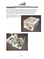
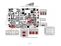
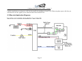
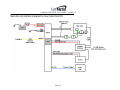
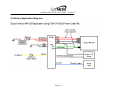
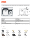
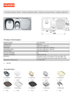
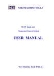
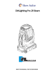
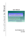
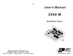
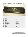
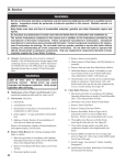
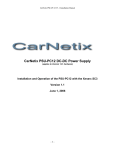
PRELIMINARY
CNX-P2140 User’s Guide
V1.2
December 14, 2006
CarNetix CNX-P2140 User’s Guide - Version 1.2
Summary of Notices & Disclaimers
CarNetix limited warranty is contingent upon proper and normal use and
installation, and does not cover damage due to external causes, including but not
limited to, accident, problems with electrical power, improper installation
techniques or materials, liquids, chemicals, oxidation, corrosion, exposure to the
elements, servicing not authorized by CarNetix, usage not in accordance with
product instructions or specifications, failure to perform required preventive
maintenance, and problems caused by use of parts and components not
supplied by CarNetix.
CarNetix makes no express warranties or conditions beyond those stated in this
warranty statement. CarNetix disclaims all other warranties and conditions
express or implied, including without limitation implied warranties and conditions
of merchantability and fitness for a particular purpose. Some states do not allow
limitations on how long an implied warranty lasts, so the above limitation may not
apply to you.
CarNetix does not accept liability beyond the remedies set forth in this warranty
statement or liability for incidental or consequential damages, including without
limitation any liability for products not being available for use or for lost data or
software.
CarNetix full warranty and return policies are stated in Section 5.0
at the end of this document.
Page 2
CarNetix CNX-P2140 User’s Guide - Version 1.2
1.0 Introduction ................................................................................................................... 4
2.0 Specifications ................................................................................................................ 6
2.1 CNX-P2140 Specifications ....................................................................................... 6
2.2 CNX-PSUmoni2140 Specifications ......................................................................... 7
3.0 Jumper Settings ........................................................................................................... 10
4.0 Current Limits ............................................................................................................. 12
5.0 Applications Wiring Diagrams ................................................................................... 13
5.1 J1 (Input Power Connector) Pin Functions ............................................................. 13
5.2 J2 (Output Power Connector) Pin Functions .......................................................... 14
5.3 Mac mini Application Diagrams ............................................................................. 15
5.4 AOpen Pandora Application Diagrams .................................................................. 17
5.5 Xenarc Application Diagrams................................................................................. 19
5.6 Installing a CNX-P5V in the CNX-P2140 .............................................................. 21
6.0 Pulse Start Feature ...................................................................................................... 22
6.1 Pulse Start Connections .......................................................................................... 22
6.2 Pulse Start Operation .............................................................................................. 22
6.2.1 What is a pulse? ............................................................................................... 22
6.2.2 Starting the PSU with a pulse .......................................................................... 23
6.2.3 Stopping the PSU with a pulse......................................................................... 23
6.2.4 Prolonging the Shutdown Delay State ............................................................. 23
6.2.5 Shutting down the PSU with double pulses ..................................................... 23
6.2.6 Ignition Override .............................................................................................. 23
7.0 Conditions of Use ....................................................................................................... 24
Page 3
CarNetix CNX-P2140 User’s Guide - Version 1.2
1.0 Introduction
The CNX-P2140 is the most powerful and intelligent regulator ever built for the CarPC
market. USB connectivity to the PSUmoni(TM) power supply monitor application takes
the guesswork out of installation, setup, and operation. Real-time gauges show exactly
what's going on under the hood! "Soft jumpers" let you tweak any parameter to your
heart's content. Firmware updates via the USB port allow you to keep your product
updated with the latest firmware with no
special programming hardware required.
There is not other product like it on the
market!
Page 4
CarNetix CNX-P2140 User’s Guide - Version 1.2
Primary Output
+12V, +18.5V, or +20V
+12V or +24V
System/Battery
Ignition
Secondary Output
+5V or +12V
CNX-P1240
Pulse Start
Optional P5V 3rd output
+5V or +12V
Delay On (Amp Control)
ACPI (relay)
iSense (Mac mini)
USB
PSUmoni
PC Application
Figure 1 CNX-P2140 Block Diagram
Page 5
CarNetix CNX-P2140 User’s Guide - Version 1.2
2.0 Specifications
2.1 CNX-P2140 Specifications
Input Voltage Range
Input Voltage Range Selection
Primary Output Voltage
Secondary Output Voltage
Maximum Ourput Currents *
(* these ratings depend upon jumper configurations of the primary and secondary
outputs)
Overall Operating Efficiency
Idle Current
Operating Temperature Range
Thermal Protection
Jumpers & Configurations
Cooling Fan
Startup/Shutdown Controller (SSC)
Processor
Firmware Upgrade
SSC Interface
+7.5VDC to +34VDC (ie +12VDC or +24VDC Systems)
Survives engine cranking
Fully Automatic (no jumpering requried)
+12V, +18.5V, +20V Jumper Selectable
+5V, +12V, +13.2V jumper selectable
Battery
Voltage
Primary
Output
Voltage
Max
Primary
Current
Primary
Output
Power
Secondary
Output
Voltage
Max Secondary
Output Current
Secondary
Output
Power
Total
Output
Power
12V
12V
11A
132W
5V
3A
15W
147W
12V
12V
11A
132W
12V
N/A
-
-
12V
20V
7.5A
150W
5V
3A
15W
165W
12V
20V
7.5A
150W
12V
3A
36W
186W
24V
12V
10A
120W
5V
3A
15W
135W
24V
12V
10A
120W
12V
3A
36W
156W
24V
20V
11A
220W
5V
3A
15W
235W
24V
20V
11A
220W
12V
3A
36W
256W
~93% at loads > 2 amps
~60mA
-10°C to +60°C
Automatic shutdown @ > +60°C
"Soft Jumpers" for many functions and delays (see PSUmoni specs for details)
Auto-sensing for +12V or +24V system (no jumpering required)
Can be used without fan for low power applications (soft jumper selectable)
Intelligent state-machine based SSC
PIC 18F4455 flash microprocessor with full speed USB
Via USB port. Download firmware upgrades from website
Full Speed USB 2.0
Page 6
CarNetix CNX-P2140 User’s Guide - Version 1.2
SSC Application Interface
Input/Output Power Cables
Chassis Dimensions
PSUmoni 2140 Windows application
Pin compatbile with standard CNX-P2140, MacPac, AOPak, and XSC8 power cable kits
4.6" x 3.25" x 1.75" (L x W x H) or 117mm x 83mm x 45mm.
2.2 CNX-PSUmoni2140 Specifications
Figure 2 PSUmoni Screen Shot
Page 7
CarNetix CNX-P2140 User’s Guide - Version 1.2
Connectivity with CNX-P2140
Full speed USB 2.0
Analog Monitor Points
Battery Voltage (Auto ranging 12V/24V systems)
Battery Current
Input Power
Primary Output Voltage (Auto ranging +12/+18.5/+20V
scale)
Primary Output Current
Primary Output Power
Secondary Output Voltage (Auto ranging +12/+5V
scale)
Secondary Output Current
Secondary Output Power
Total Output Power (Primary + Secondary)
Overall Efficiency (Total Output Power/Total Input
Power)
Temperature (0-60°C)
Digital Monitor Points
Battery OK
Primary Output Current OK
Secondary Output Current OK
Machine State Indicator
State Timers
Ignition Status (On/Off)
Pulse Start Status (On/Off)
Fan Status (Ok/Fault)
Delay ON Status (On/Off)
ACPI (power button) Status (On/Off)
Power Good Status (Regulator On/Off)
PS_ON Status (Regulator Control On/Off)
USB Connection Status (Connected/Not Connected)
Shutdown Delay Time (Minutes 0-59, Hours 0-3)
Page 8
CarNetix CNX-P2140 User’s Guide - Version 1.2
Control Sliders
Deadman Timer (0-120 Hours)
DelayON Timer (0-60 Seconds)
Bootup Lockout Timer (0-120 Seconds)
Shutdown Lockout timer (0-120 Seconds)
Low Battery Detection Threshold (9V - 24V)
Soft Jumpers
Standby Mode (On/Off)
Secondary Output ON (Ignition/DLYON)
Secondary Output OFF (PriOut/Ignition)
Fan (Enable/Disable)
Firmware Upgrades
Firmware upgrades applied to P2140 via USB port
Page 9
CarNetix CNX-P2140 User’s Guide - Version 1.2
3.0 Jumper Settings
It is important that you properly set the hardware jumpers before applying power to the
P2140. Please select the following:
•
•
•
•
•
•
•
Primary output voltage (JP1)
o Selectable for +12V, +18.5V, or +20V output
Secondary output voltage (JP2)
o Selectable for +5V or +12V output
JP3 Option Jumpers
o Various options utilize the JP3 jumper header. These include:
Pins 1-2: Pulse Start input connection (see section 6)
Pins 3-4, and 5-6 are unused at this time
Pins 7-8: Programming jumper used to upload new firmware (see
the Firmware Upgrade Guide)
Pins 9-10: Used to control the optional P5V regulator (see section
5.6)
Input to Secondary output regulator (JP4)
o See JP4 configuration matrix for proper settings. Depends on battery
voltage, primary output voltage, and secondary output voltage
PC or Mac operation (JP5)
o This sets the dual-function iSense/ACPI- output pin for the appropriate
functionality. If using a PC, this setting completes the ACPI relay output
circuit. If using a Mac mini, this output connects the iSense signal to the
Mac.
Mac mini classic or Intel Mac mini operation (JP5)
o This jumper selects either a 6.8k resistor (Mac mini classic) or a 3.4k
resistor (Intel Mac mini) for iSense.
ACPI Isolated Relay Output (JP6)
o This output is provided for those who were previously using a P1900 (or
Xenarc PC-PSU19) so that you do not have to change the existing wiring.
JP6 provides similar functionality to JP3 on the P1900 (i.e. isolated relay
output for ACPI signal).
Figure 2 below shows the locations and settings for the various hardware configuration
jumpers.
Page 10
CarNetix CNX-P2140 User’s Guide - Version 1.2
Figure 3 P2140 Jumper Locations and Settings
Page 11
CarNetix CNX-P2140 User’s Guide - Version 1.2
4.0 Current Limits
The flexibility of the P2140 allows the user to select several different operating
configurations. Since the battery input can be either +12V or +24V, and the primary
output can be +12V, +18.5V, or +20V, and the secondary output can be either +5V or
+12V, the P2140 has various current limits depending upon the jumper settings. These
current limits are summarized in the table below. If these current limits are exceeded, the
P2140 will go into forced shutdown.
In the case where the input to the secondary output regulator is fed from the output of the
primary regulator, the current limit is the sum of BOTH the primary and secondary
currents. Theses configurations are shaded in the table below. The combined maximum
current limit is shown in the right hand column.
(Note: in the table below V(pri) =20 refers to either +18.5V or +20V operation)
V(in)
12
12
12
12
24
24
24
24
V(pri)
12
12
20
20
12
12
20
20
I(pri)(max)
11
11
7.5
7.5
10
10
11
11
P(pri)
132
132
150
150
120
120
220
220
V(sec)
5
12
5
12
5
12
5
12
I(sec)(max)
3
N/A
3
3
3
3
3
3
P(sec)
15
15
36
15
36
15
36
P(total)
147
165
186
135
156
235
256
sec
jumper
batt
N/A
batt
pri
pri
batt
pri
batt
max
i(pri)+I(sec)
N/A
N/A
N/A
7.5
10
N/A
11
N/A
Table 1 P2140 Current Limits
In addition to the current limits above, when in standby, the P2140 will limit both
primary and secondary output currents to .5 amps each. If the current of either output
exceeds .5 amps, the P2140 will automatically exit standby mode and cut power to both
outputs.
Page 12
CarNetix CNX-P2140 User’s Guide - Version 1.2
5.0 Applications Wiring Diagrams
5.1 J1 (Input Power Connector) Pin Functions
The connector comes with “pigtails”, or short lengths of wire that allow you to splice
longer runs of larger gauge wire from your battery and ground connections. J1 is the 6pin input power connection from your battery and ignition signal.
Pin
1
2
3
4
5
6
Wire Color
Black
Blue
Red
Black
Yellow
Red
Function
Ground
Pulse Start Input (See Section x)
+12V Battery Input
Ground
Ignition/ACC input
+12V Battery Input
Table 2 – P2140 J1 Pin Assignments
Page 13
CarNetix CNX-P2140 User’s Guide - Version 1.2
5.2 J2 (Output Power Connector) Pin Functions
The connector comes with “pigtails”, or short lengths of wire that allow you to splice
longer runs of larger gauge to your computer & peripherals. J2 is the 8-pin output power
connector that feeds power to your PC, screen, USB devices, and other peripherals.
Pin
1
2
3
Wire Color
Red
Black
White
Function
Primary Output 1
Ground 1
ACPI-/iSense
4
5
6
7
Blue
Red
Black
Brown* (may look
purple)
Green
DLYON Out
Primary Output 2
Ground 2
Secondary Output
8
ACPI+
Table 3 – P2140 J2 Pin Assignments
Page 14
Comment
Dual function,
depends on jumper
setting
CarNetix CNX-P2140 User’s Guide - Version 1.2
CarNetix manufactures several power cable kits that simplify the installation of your P2140. When using these power cable kits, you
will not need to use the “pigtail” power connectors that come with the P2140.
5.3 Mac mini Application Diagrams
Page 15
CarNetix CNX-P2140 User’s Guide - Version 1.2
Page 16
CarNetix CNX-P2140 User’s Guide - Version 1.2
5.4 AOpen Pandora Application Diagrams
Page 17
CarNetix CNX-P2140 User’s Guide - Version 1.2
Page 18
CarNetix CNX-P2140 User’s Guide - Version 1.2
5.5 Xenarc Application Diagrams
Page 19
CarNetix CNX-P2140 User’s Guide - Version 1.2
Page 20
CarNetix CNX-P2140 User’s Guide - Version 1.2
5.6 Installing a CNX-P5V in the CNX-P2140
The CNX-P5V can be added to the P2140 to provide a third regulated output. This output
is typically used to power +5V USB devices, while the P2140 primary output powers the
computer (+19V), and the secondary output powers your screen (+12V).
The CNX-P5V is installed into the P2140 exactly the same way as described in the P5V
Installation Manual for the P1900, except for the naming of the jumpers. When following
the installation instructions in the P5V manual, make the following jumper name
changes.
Function
Battery Input
On/Off Control
P5V Wire color
Red/Black
Green/Black
P1900 Jumper
JP5 (pins 1&2)
JP4 (pins 2&3)
See Section 3 for the location of JP3 & JP4 on the P2140.
Page 21
P2140 Jumper
JP4 (pins 1&2)
JP3 (pins 9&10)
CarNetix CNX-P2140 User’s Guide - Version 1.2
6.0 Pulse Start Feature
The CNX-P2140 includes a feature that allows you to remotely start and stop the PSU.
This feature is called “Pulse Start”. This feature would normally be used in conjunction
with a wireless device such as a car alarm with auxiliary inputs/outputs or a WiFi device
with Wake-On-LAN (WOL) features.
6.1 Pulse Start Connections
The Pulse Start input can either be an externally applied voltage (ie +5v or +12V) pulse,
or a momentary relay contact closure. The externally applied voltage pulse is connected
to Pin 1 of J1 using the Blue wire. The momentary relay contact closure is connected to
Pins 1&2 of JP1 (see Section 2.2 for location). You can use either or both of these
connections to start/stop the PSU.
6.2 Pulse Start Operation
6.2.1 What is a pulse?
Voltage Pulse on Pin 1 of J1
When connecting to Pin 1 of J2, the “pulse” must be a voltage that transitions from 0V to
+V, and then transitions back to 0V. The SSC will wait (hang) if the voltage stays high
without going back to 0V after the initial transition from 0V to +V.
The value of the +V can be any voltage from approximately +2V to +20V. Typical
voltages are +5V or +12V. The value of 0V must be below +.2V or open circuit (ie you
could drive this input with a relay that momentarily connects to a +12V source and then
provides an open circuit).
The current required to drive this input is very low (milliamps).
Contact Closure Pulse on Pins 1&2 of JP1
When connecting to Pins 1&2 of JP1, the “pulse” must be a low resistance metallic
contact closure (i.e. relay) that transitions from OPEN to CLOSED, and then back to
OPEN. The SSC will wait (hang) if the contact closure remains CLOSED after the initial
transition from OPEN to CLOSED.
The current passing through this relay is very small (milliamps) so a low power relay can
be used.
Pulse Width
The pulse width can be any value from a minimum of approximately 100mSec to several
seconds. As mentioned above, if the pulse is very long the SSC will wait for the transition
back to the normal state before continuing.
Page 22
CarNetix CNX-P2140 User’s Guide - Version 1.2
6.2.2 Starting the PSU with a pulse
When the PSU is in Idle State and an externally applied pulse is applied to the Pulse Start
input, the PSU will power up normally, as it would if the Ignition line had gone high.
During the Bootup Lockout State any input pulse is ignored.
6.2.3 Stopping the PSU with a pulse
After the normal power up sequence, and while in Runs State, the SSC monitors the
Pulse Start input for a shutdown pulse. If a single shutdown pulse is sensed, the PSU goes
into the Shutdown Delay State. However, if control has been passed to the Ignition line
(see Ignition Override below) the Pulse Start input is ignored.
6.2.4 Prolonging the Shutdown Delay State
If, while in the Shutdown Delay State, a single pulse is detected, the Shutdown Delay is
restarted at its original value in order to prolong the Shutdown Delay. This is useful for
occasionally downloading large files that would take longer than the normal Shutdown
Delay time.
Once the Shutdown Delay has timed out, the PSU enters the Shutdown Lockout State. At
this point the SSC ignores any pulse input until the PSU enters the Idle State.
6.2.5 Shutting down the PSU with double pulses
If two pulses are detected within a 5 second window during the Shutdown Delay State the
PSU will skip any remaining Shutdown Delay Time and immediately enter the Shutdown
Lockout Sequence. This feature is useful for shutting down the CarPC when your file
transfer process is completed.
6.2.6 Ignition Override
If, after the PSU has been started by a pulse, the Ignition is turned on, control is passed to
the Ignition line. Once the Ignition line has gained control of the SSC it will be able to
shutdown the PSU as if it had initially started it. This feature is useful when you wish to
remotely start the CarPC with your wireless device, but then get into your car and drive.
Page 23
CarNetix CNX-P2140 User’s Guide - Version 1.2
7.0 Conditions of Use
1 Year Limited Warranty
CarNetix warrants that the products it manufactures will be free from defects in materials and
workmanship. The warranty term for all products is 1 Year beginning on the date of invoice. During
the warranty period CarNetix will repair or replace, at our discretion, products covered under this
limited warranty that are returned to CarNetix using a valid RMA number.
Service & Support
CarNetix provides a free on-line technical support forum for diagnosing hardware problems with your
system throughout the warranty period. Free technical support service is limited to configuration and
operation of hardware sold by CarNetix.
Returning Merchandise
If we determine that a part is defective a replacement can be after Purchaser obtains a Return
Merchandise Authorization (RMA) number. Purchaser must first contact us to obtain an RMA number
before attempting to return any part. Parts returned without first obtaining an RMA number shall not
be accepted, repaired, or replaced.
To obtain an RMA number, Purchaser must follow these procedures
1. Email us at [email protected] to receive your RMA number;
2. The RMA Number must be used within THIRTY (30) DAYS, or it will not be honored;
3. The RMA Number MUST BE SHOWN CLEARLY ON YOUR SHIPPING LABEL;
4. CarNetix must receive all Returns before a replacement will be sent, unless a valid credit card
number has been given to secure payment for the replacement part;
5. Include a copy of the Invoice on which the product(s) was shipped to you;
6. All RMA Returns must be shipped to CarNetix with freight PREPAID. Any Returns with freight
collect or COD will be refused and returned to you;
7. CarNetix must RECEIVE all returned goods within the warranty period.
Limitation Of Liability
This limited warranty is contingent upon proper and normal use and installation, and does not cover
damage due to external causes, including but not limited to, accident, problems with electrical power,
improper installation techniques or materials, liquids, chemicals, oxidation, corrosion, exposure to the
elements, servicing not authorized by CarNetix, usage not in accordance with product instructions or
specifications, failure to perform required preventive maintenance, and problems caused by use of
parts and components not supplied by CarNetix.
CarNetix makes no express warranties or conditions beyond those stated in this warranty statement.
CarNetix disclaims all other warranties and conditions, express or implied, including without limitation
implied warranties and conditions of merchantability and fitness for a particular purpose.
Some states do not allow limitations on how long an implied warranty lasts, so the above limitation
may not apply to you.
CarNetix does not accept liability beyond the remedies set forth in this warranty statement or liability
for incidental or consequential damages, including without limitation any liability for products not
being available for use or for lost data or software.
Shipping & Returns
Page 24
CarNetix CNX-P2140 User’s Guide - Version 1.2
Shipping Locations and Methods
We ship both domestically (via UPS) and to most international locations (via USPS). Shipping charges
do not include import taxes or customs fees. We are not responsible for loss or damage to uninsured
packages. If you have a special shipping requirement or request, please notify us when you place your
order or via email at [email protected].
Return Shipping Policy
The Purchaser must pre-pay shipping and costs including insurance for any defective system or parts
returned under our warranty. CarNetix shall not be liable for risk of loss or damage during shipment of
your returned system or parts if you fail to insure the shipment. All products must be shipped back to
CarNetix in their original or equivalent packaging. CarNetix will ship the repaired or replacement
product(s) to Purchaser via Ground Service (freight prepaid) if you use an address in the continental
United States. For shipments to other locations, Purchaser must pre-pay any shipping charges,
insurance, export taxes, custom duties and taxes including VAT taxes, or any other charges associated
with transportation of your CarNetix products. Purchaser assumes the risk of loss. CarNetix shall not
be responsible for failure of the delivery service to make on-time delivery. If Purchaser requests a
shipping method other than Ground Service, Purchaser must pre-pay the difference in cost before
CarNetix will ship the replacement product.
Product Return Policy
If you are an end-user customer who purchased products directly from CarNetix, you may return the
product to CarNetix within thirty (30) days of the purchase date for a refund of the purchase amount
minus a 15% re-stocking fee. Shipping charges and insurance are not included and will not be
refunded to you.
Returned products must be in as-new condition, and include all components, cables and all other items
that were included with product. Failure to meet this requirement will result in an additional 10%
restocking fee (25% total) being deducted from your refund. You must follow the conditions outlined
below in order to obtain your refund: Before any return, an RMA number must be obtained from
CarNetix in accordance with the aforementioned RMA Policy.
To receive a refund, the returned product must be received at our factory within thirty (30) days from
the date that the RMA is issued and within ninty (90) days from the purchase date. If your product is
not received within thirty (30) days of the RMA being issued, but it is received within ninty (90) days of
your purchase date, then you shall be charged 25% of your invoice amount as a restocking fee. If your
product is not received within ninty (90) days of your purchase date, then you shall not be entitled to
any refund.
Upon CarNetix receipt of your returned product and verification that same has not been damaged,
altered or is missing any other original shipping items, you will receive a refund minus re-stocking fee,
normally within fourteen (14) days from the date the system is received. Your refund amount will be
reduced for any missing parts, components, other original shipping items or damage or alteration to the
product. CarNetix will not accept any unauthorized returns. Any merchandise returned without first
obtaining an RMA number shall be rejected and returned to you at your expense.
Page 25