1
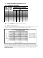
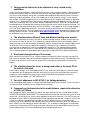
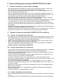
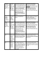
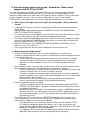
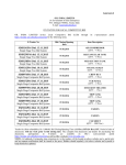
Frequently Asked Questions on the SURETECH HV/PT2 and HV/PA
Contents
1
What are the operating distances of HV/PT2.....................................................................................2
1.1.1
Sensor operating distance (table)........................................................................................2
2 Can the HV/PT2 be used to measure voltage....................................................................................2
2.1
YES, reasonably accurately: ......................................................................................................2
3 Varying results that exist in the situation of rainy, humid or dry conditions.........................................3
4 The situation where different lines and different voltages are present................................................3
5 Directional characteristics of the sensor ............................................................................................3
6 The situation where the tester is being used either in the hand, OR at the end of a link stick ............3
7 For strict adherence to IEC 61243-1 for Voltage detectors ................................................................3
8 Comments on flashover due to the small distance required for detection of 132kV of 250mm...........3
9 Notes on picking up and leaving the SURETECH HV/PT2 on a table................................................4
9.1
General considerations of electric fields in buildings...................................................................4
9.2
Examples of various users placing the SURETECH HV/PT2 on a table top ...............................4
9.2.1
Example 1 (Insulated table legs, earthed user)....................................................................4
9.2.2
Example 2 (Earthed table legs, insulated user) ...................................................................4
9.2.3
Example 3 (Earthed table and earthed user) .......................................................................4
9.2.4
Example 4 (Different users at the same table).....................................................................5
9.2.5
Example 5 (Picking up and leaving the HV/PT2 on the table)..............................................5
9.3
Conclusion and Recommendations ............................................................................................5
10
Table of some possible uses of SURETECH HV/PT2 indicating Appropriate useage and
Inappropriate usage of the tester: .............................................................................................................6
11
How do cheaper testers such as pen / screwdriver / Neon testers compare with HV/PT2 or
HV/PA? ....................................................................................................................................................8
11.1
Where does the energy come from to light the sensing light – Battery-less Neon testers?......8
11.2
Battery powered voltage testers?............................................................................................8
11.3
Conclusion: Do you want SAFETY or do you want PRICE?....................................................9
1 What are the operating distances of HV/PT2
1.1.1 Sensor operating distance (table)
Phase
Line
HV/PT2
Volts
Voltage
Operating Distance [ milli-meters ]
(to earth)
(line to
With Handle (at HV/PT2 setting given
[ Volts ]
line)
here)
[ Volts ]
380V
11kV
33kV
66kV
132k
V
110
190
20
220
380
40
303
525
60
635
1 100
140
25
1 905
3 300
300
90
3 811
6 600
600
170
30
6 351
11 000
1000
240
50
20
8
12 702
22 000
2000
460
150
50
20
19 053
33 000
3000
600
240
100
50
38 105
66 000
1200
400
240
110
76 210
132 000
2400
1000
450
220
2 Can the HV/PT2 be used to measure voltage
2.1
YES, reasonably accurately:
When the user deploys the HV/PT2 on a handle or telescopic link stick, then the distances shown in the
table above are relevant. This same information is conveyed in a graph as follows:
To measure voltage, the user would set the HV/PT2 on a known setting, then measure the distance at
which the instrument operates (LED and buzzer just turning ON), draw a horizontal line to intersect with
the appropriate graph (switch setting on the HV/PT2), and then note the phase voltage on the bottom
horizontal axis. This process can and should be repeated at various HV/PT2 instrument settings to
establish better accuracy.
3 Varying results that exist in the situation of rainy, humid or dry
conditions.
Under humid or wet conditions, corona discharge can occur even at medium voltages. Corona discharge
creates short impulses often less than one micro second, and spaced apart by tens of micro seconds.
The result is high frequency energy that is available to be coupled into the proximity sensor. Due to the
capacitive coupling of proximity sensors, the coupling to this high frequency energy is much stronger
than at 50Hz, so spurious triggering results in some proximity testers leading to uncertainty in operating
distance. This is fundamental to the consistency of operating distance with proximity sensors, which has
led to much uncertainty with users of these devices. Guided by ESKOM in 1995-1997 we embarked on
the development of a fundamentally new way of sensing to filter out the effects of corona discharge. The
consistency of operating distance which the HV/PT2 exhibits is very good even under varying conditions.
Our HV/PT2 was approved by ESKOM in June 1998, and we understand that it is the only ESKOM
approved proximity tester. (As a by-product of this new technology that we developed has come a range
of highly accurate sensors - see our website http://www.suretech.co.za , and many more products will
be developed in the years to come.)
4 The situation where different lines and different voltages are present
The use of the proximity sensor on a link stick on VARIOUS voltage settings, enables the user to assess
the ACTUAL VOLTAGE on the line. This is particularly important when a line has for example just been
tripped, and the user needs to establish the following: whether THIS particular line as been tripped, and if
so whether the line is receiving a BACKFED voltage OR, whether the line is subject to an INDUCED
VOLTAGE from an adjacent line, OR has no appreciable voltage on it. The induced voltage could be
lower, but CAN STILL BE LETHAL. It is advisable to cross-check by assessing the actual voltage level.
This is achieved by observing the operating distance graphs in the HV/PT2 User Manual or brochure.
5 Directional characteristics of the sensor
When used in the hand, HV/PT2 has a Cosine response characteristic. When used at the end of a link
stick, the user should be aware of the electric field pattern for most effecitve results. For advanced users
we offer a training course in the nature of electric fields, and how they are affected in the measuring
process.
6 The situation where the tester is being used either in the hand, OR at
the end of a link stick
For the higher voltages, a link stick deployed HV/PT2 can return more accurate assessment of voltage
on a particular line. By doing measurements close to the line using a link stick (rather than hand use),
enables the user to establish (by measuring the electric field NEAR the conductor) much more
accurately what the voltage is on THAT particular line.
7 For strict adherence to IEC 61243-1 for Voltage detectors
A link stick adapter probe spacer is available for direct conformance to the standard. To use the tester as
an extension to the standard, the user should consult the factory
8 Comments on flashover due to the small distance required for detection
of 132kV of 250mm
The Occupational Health and Safety-Act requires the larger distance, but this is for absolute minimum
OPERATOR WORKING CLEARANCE. The working clearance at the end of the link stick, is the link stick
length itself, (assuming the link stick has been approved, tested and is clean etc.) The HV/PT2 can even
be placed onto the 132kV line without damage to itself or danger to the operator, so long as the link stick
is safe. It is however not good practice to place the HV/PT2 onto the HV line, as the field can be
extremely high at the conductor, and subjecting the tester to localised discharge which can degrade the
box insulation (see User Manual for further information). This is however not dangerous to the operator.
Correct use is to move the HV/PT2 nearer and further away from the line about 250mm distance on the
correct voltage setting. The tester should beep around that operating distance.
9 Notes on picking up and leaving the SURETECH HV/PT2 on a table
9.1
•
•
•
•
•
•
•
•
General considerations of electric fields in buildings
Stray electric fields from the 220Vac (or 110Vac) mains will couple with all items in a room; these
items include humans as well as furniture such as tables, chairs, floors, walls etc.
Each of these items will be capacitively coupled to the mains live conductors depending on where
the mains cable is relative to a given item
Mains generated electric fields will be present from mains socket outlets and lighting. If there is an
electrical appliance connected to the plug, then the cable connecting the appliance to the mains will
also contribute to generating the electric field that capacitively couples to the item.
Now each of the above mentioned items itself will have electrical properties including a capacitive
dielectric constant that will act to channel more or less of the electric field
For example the dielectric material of a plastic table will channel the electric field through it at a factor
of 5 times greater than that of air (assuming the relative permittivity of the plastic table is 5)
If the table is wood, then perhaps there is water content in the wood which will tend to reduce the
electric field, or possibly make the entire table top at the same potential, which may or may not be at
earth potential
Depending on the electrical properties of the table legs, they could either connect the table top to the
floor (which is probably at earth potential, but not always)
Remember that a magnetic field is not the same as an electric field. The magnetic field is set up from
the presence of a current, and an electric field is set up from the presence of a voltage
9.2
Examples of various users placing the SURETECH HV/PT2 on a table top
9.2.1 Example 1 (Insulated table legs, earthed user)
If the table legs are insulated from earth (eg. dry wood, or non-conducting plastic) then there will not
be a discharge path from the table top to earth, and the table top could easily be at a potential of a
hundred volts or more above earth, if an electric cable was close by
• Now if a user at earth potential (bare feet) holds a SURETECH HV/PT2 near to the table, then the
HV/PT2 will detect the presence of this voltage and it will beep
• All the user needs to do is touch the table with his other hand and thereby equalise the table top
voltage to his body, then the HV/PT2 will stop beeping
• In this case the user is earthed and the table top is live
•
•
•
•
•
•
•
•
•
9.2.2 Example 2 (Earthed table legs, insulated user)
Assume a table is conductive and is resting on (electrically connected to) earth, then any capacitively
coupled current from stray electric fields (from mains cables) will be coupled to earth
This will result in the table being at earth potential (ie. zero volts) and it will conduct any small stray
capacitively coupled currents to earth
Then lets assume the HV/PT2 operator is wearing rubber soled (electrically insulated) shoes, and
thereby making the user electrically insulated from earth
Lets also assume that the user is near a mains cable, such as a light in the ceiling or cable
connected to an electrical appliance. The appliance does not even have to be ON, and there still will
be an electric field from the live trailing cable
This electric field will capacitively couple to the user, thereby making him / her live at a voltage
depending on the capacitive coupling distance, and insulation properties of the user's shoes, as well
as the mains voltage
Now when the user brings the HV/PT2 near to the table top, the tester will most probably beep just
before it touches the table
Again the tester is doing what it is supposed to do, by detecting a voltage difference between the
user and the table top
In this case the user is live and the table top is earthed
9.2.3 Example 3 (Earthed table and earthed user)
• Assume a conductive table top, and a user that are BOTH connected to earth, with electric cables far
away
• An approaching HV/PT2 will not beep because the table and the operator are at the same potential
•
The HV/PT2 again behaves correctly
9.2.4 Example 4 (Different users at the same table)
• Assume one operator is at the one end of the table, and another operator is at the other end of the
table
• Various combinations of table electrical properties, shoe properties of both users, and where the
electric cables in the environment couple their electric field, will determine whether the user AND /
OR the table top will be live OR at zero volts, and whether the users are live or at zero volts
• Whenever there is a potential difference between a user and the table, the tester will beep just before
(and perhaps after) the tester touches the table
9.2.5 Example 5 (Picking up and leaving the HV/PT2 on the table)
• When the HV/PT2 is left resting on the table without the user holding it, it will take up the same
potential as the table and it will stop beeping as the user moves away
• If a user approaches an HV/PT2 that is resting on the table top, just before he touches it, the tester
will beep if there is a voltage difference between the user and the table top
9.3
•
•
•
•
•
Conclusion and Recommendations
We all live in and around stray electric fields in our homes, which are set up by electric cables carried
through walls, cables to appliances and lighting
The SURETECH HV/PT2 is very sensitive to these electric fields. It is electric fields that the HV/PT2
has been designed to detect. The electric field contains all of the information of the voltage on the
conductor that causes the electric field.
Even for low voltages (tens of volts), the HV/PT2 can detect these voltages when it is held very
close.
When an HV/PT2 is placed on a table or any other surface and beeps, then the tester is doing what it
is supposed to do, by detecting a difference in voltage between the user of the instrument, and the
table (or other surface)
Users of HV/PT2 should not jump to the conclusion that the tester is faulty if it behaves differently
with different users; they are probably occupying different space in the room and therefor are at a
different voltage; and they may have different characteristics of shoe insulation from each other
10 Table of some possible uses of SURETECH HV/PT2 indicating
Appropriate useage and Inappropriate usage of the tester:
The table indicates some typical uses of HV/PT2. The table is by no means exhaustive, and is meant to
be a guide:
Scenario
3 phase 11kV,
(or 380V etc)
cable buried in
ground
3 phase 11kV
(or 380V etc)
cable, phases
exposed,
separated but
insulated
220V live /
neutral / earth
Cab-tyre cable
Test
Cable
armouring
Appropriate use of HV/PT2
If an earth on some part of the
power system is removed (or
stolen), then remaining cable
armouring could easily
become live and dangerous.
Under these circumstances the
armouring could become live
and dangerous. HV/PT2 will
pick up any voltage on the
armouring of the cable.
HV/PT2 operating distance will
give an indication of the
voltage.
Individual
HV/PT2 used with SURETECH
phases
handle (11kV or 50Kv) will
provide an estimate of voltage
on each phase. User should
be able to differentiate
between a back-feed voltage
versus induced voltage, both
of which could be lethal
Test outside HV/PT2 will operate at about
cable to see 30mm hand held
whether
cable is
energised
220V live only
Test
through
insulation
HV/PT2 will operate at about
100mm hand-held
Telkom line
running on
shared service
poles under
ESKOM /
Municipal MV
line
Test
TELKOM
cable
screen
nearby to
MV line
Only skilled technicians who
have been specially trained
should be allowed to operate
on or near live MV equipment,
closer than the safe approach
distances specified by
ESKOM. The HV/PT2 (or
preferably HV/PT2) can be
used by a skilled technician.
Inappropriate use of HV/PT2
DON'T EXPECT TO SEE
WHETHER A CABLE IS LIVE
THROUGH THE ARMOURING!!!!
Under normal circumstances, the
armouring will be earthed and will
also kill the electric field generated
by the conductors in the cable
Can use HV/PT2 hand-held, but
operator's hand should never
encroach closer than the safe
operating distance
Don't hold a live insulated cable in
one hand TOO CLOSE THE
POINT OF MEASUREMENT, and
the other hand holding the HV/PT2
tester. The operators hand that is
holding the cable will kill the
electric field, thereby de-sensitising
HV/PT2
Don't hold a live insulated cable in
one hand TOO CLOSE THE
POINT OF MEASUREMENT, and
the other hand holding the HV/PT2
tester. The operators hand that is
holding the cable will kill the
electric field, thereby de-sensitising
HV/PT2
Close proximity to the MV line
should be avoided as the electric
field of the MV line could
predominate, depending on the
exact geometry of the situation
Telkom line
running on
shared service
poles under
ESKOM /
Municipal MV
line
Test
TELKOM
cable
screen FAR
AWAY from
MV line,
e.g. inside
TELKOM
junction box
Telkom line
running
NEARBY
ESKOM /
Municipal
overhead MV
line
Telkom line
running
NEARBY
ESKOM /
Municipal
overhead MV
line
Test
TELKOM
cable
screen
NEARBY
the MV line
LV bundled
cable
LV bundled
cable is not
screened,
and so
voltage
present on
each phase
can be
tested
MV bundled
cable is
screened
and the
screen is
normally
earthed.
MV bundled
cable
Test
TELKOM
cable
screen FAR
AWAY from
MV line,
e.g. inside
TELKOM
junction box
It should be standard practice
for technicians to test for HV
whenever they open a junction
box. A hand-held HV/PT2 can
be used, to determine whether
a MV line has fouled with the
Telkom line SOMEWHERE
ELSE in the system. If a high
voltage is present in the
junction box, then a more
accurate assessment of
voltage should be made with
the HV/PT2 on a SURETECH
handle.
HV/PT2 can be used handheld or with SURETECH
handle.
DON'T EXPECT TO SEE
WHETHER HV IS PRESENT
WITHIN A JUNCTION BOX
THROUGH THE STEEL DOOR!!!!
Under normal circumstances, the
door and junction box will be
earthed and will eliminate any
electric field generated by HV
conductors inside the junction box.
Close proximity to the MV line
should be avoided as the electric
field of the MV line could
predominate, depending on the
exact geometry of the situation
It should be standard practice
for technicians to test for HV
whenever they open a junction
box. A hand-held HV/PT2 can
be used, to determine whether
a MV line has fouled with the
Telkom line SOMEWHERE
ELSE in the system. If a high
voltage is present in the
junction box, then a more
accurate assessment of
voltage should be made with
the HV/PT2 on a SURETECH
handle.
With HV/PT2 close to the
individual phase, through the
insulation, testing can be done
to determine whether voltage
is present on each phase.
DON'T EXPECT TO SEE
WHETHER HV IS PRESENT
WITHIN A JUNCTION BOX
THROUGH THE STEEL DOOR!!!!
Under normal circumstances, the
door and junction box will be
earthed and will eliminate any
electric field generated by HV
conductors inside the junction box.
A test near the earth screen
will establish whether the
screen itself has been earthed,
and as such this a good test to
make with HV/PT2. The other
useful test to make with
HV/PT2 is at the end of the
bundled cable, where it is
terminated.
There should normally never be
any electric field around a MV
bundled cable even when the cable
is energised, so HV/PT2 should not
be used
Far-field DIMINISHES RAPIDLY
with distance due to 3 phases
cancelling each other, so only very
close proximity testing can be done
(about 5 mm)
11 How do cheaper testers such as pen / screwdriver / Neon testers
compare with HV/PT2 or HV/PA?
There are major differences between HV/PA and HV/PT2 versus a Neon type electric field testers.
The main similarity between HV/PA and HV/PT2 versus Neon tester is they both operate using
capacitive coupling. Neon testers often come in the shape of a pen or screwdriver. The user then points
the pen / screwdriver at the HV source in order to make it light up. There are some MAJOR
DEFICIENCIES in Neon type testers, and so a price comparison between them is not sensible.
11.1 Where does the energy come from to light the sensing light – Battery-less Neon
testers?
•
•
•
•
•
•
HV/PA and HV/PT2 testers extract the energy to light the LED and sound the buzzer from the
internal battery.
Neon type testers without batteries extract the ENERGY TO LIGHT THE SENSOR LAMP,
DIRECTLY FROM THE HV SOURCE!!!
This means that the user has to approach much closer to the HV source with a battery-less Neon
tester to extract enough energy from the HV source to power the Neon lamp.
For voltages higher than about 400Vac (and even in some LV circumstances) battery-less Neon
testers are simply downright DANGEROUS, as they interfere so severely with the electric field,
they actually place the user’s life in DANGER.
Battery-less Neon testers should NEVER BE USED ON MV AND HV SYSTEMS. The user
places his life at risk if he does this.
Users may get away with them for some LV applications, but never MV or HV!!
11.2 Battery powered voltage testers?
•
•
•
•
For pen / screwdriver type testers (that use an internal battery), the use of these pen /
screwdriver shaped instruments often rely on the insulation of the instrument to prevent flashover
or electrocution of the user.
o The user may even be tempted to touch the voltage source by thinking it is insulated!!
o The level of insulation on these testers is simply not adequate for use in MV and HV
applications (ie. Above 1000Vac), and will result in extremely dangerous operating
conditions.
When introducing a pen / screwdriver type instrument into an MV or HV electric field, the electric
field is altered by sharpening the field at the pointed end of the pen / screwdriver
o If the user brings the pen / screwdriver closer to the MV or HV equipment, the electric field
is greatly increased as the user shortens the distance to source.
o As the pen / screwdriver instrument sharpens the electric field, this can cause dangerous
electric field gradients even if contact is not made; breakdown in MV / HV insulation could
occur, resulting in lethal conditions.
o With HV/PA or HV/PT2 the sensor plates are designed to be flat and low profile, to
minimise the creation of sharp points and high electric field gradients
Distance of operation indicates the voltage
o Using pen / screwdriver type testers, the user with his pointed pen actually DISTORTS
THE ELECTRIC FIELD, which is dangerous and diminishes the possibility of measuring
the voltage on MV and HV.
o With HV/PA and HV/PT2 the field is not distorted when used with a SURETECH handle or
link stick; so then the user is able to return consistent and SAFE sampling of the source.
o With a little understanding, the HV/PT2 can actually measure the MV or HV voltage in an
extremely safe manner.
The HV/PA and HV/PT2 instruments use a SURETECH proprietary sensing circuitry that is
linear, AND extremely sensitive, AND have built-in circuits to protect the instruments against
even the highest voltages used on the planet (760kVac)
o The importance of linear sensing means that the HV/PA and HV/PT2 actually FILTER
OUT frequency components above about 400 Hz, such as from switching transients,
corona discharge and partial discharge; this interference is eliminated while the 50 / 60 Hz
components are properly measured and detected.
o This topology results in HV/PA and HV/PT2 being MUCH MORE STABLE in MV and HV
applications than instruments that have not implemented this technology
We feel sure that pen / screwdriver type instruments do NOT use linear sensing but rather
threshold detectors, and would offer FAR LESS CERTAINTY in measurement, resulting in
much less deterministic or safe detection.
Battery compartment
o The HV/PA and HV/PT2 are extremely robust, and can suffer high levels of rough
treatment without damage. The battery compartment has built in battery support on the
shoulder of the battery, which makes it IMPOSSIBLE FOR BATTERY TERMINALS TO
BECOME DISTORTED FROM AN INSTRUMENT BEING DROPPED. This simple design
attribute on such an important part of the instrument ensures HV/PA battery remains
ready for action even after a fall or being dropped.
o We are not aware of other SAFETY Testers that have this level of SAFETY design built
into the instrument’s battery compartment.
Sensitivity of sensing circuits
o Great care in the design of HV/PA and HV/PT2 has been taken to ensure the front ends
are consistent and ultra-sensitive; resulting in users being able to know what voltages or
electric fields they are dealing with far away from the HV source.
o If the user approaches an MV or HV source, the HV/PA will switch itself ON and alert the
user WELL OUTSIDE THE SAFE APPROACH DISTANCE FOR MV OR HV
EQUIPMENT.
o If the user continues to advance toward the MV or HV source, the HV/PA increases it’s
beep & flash rate and will reach it’s screaming pitch of 20Hz BEFORE THE SAFE
APROACH DISTANCE IS ENTERED!!!
o This level of design detail has not been achieved with pen / screwdriver type testers. To
get adequate levels of sensitivity and consistency from cheap instruments would be a
tremendous challenge.
HV/PA is ON all of the time, it does not have an ON/OFF switch
o HV/PA has two receivers, one to switch the instrument ON and the other to measure.
Most pen / screwdriver type voltage sensors with batteries, are required to be switched on
by the user.
o If the HV/PA is worn on the wrist when approaching or operating near live equipment, the
HV/PA provides the best opportunity for a user to be alerted.
o The HV/PA is effectively ON and ready for use at all times, without the user needing to
remember to switch it ON.
o The HV/PA can be worn on the wrist and with it’s non-pointed, flat profile does not alter or
cause MV or HV electric fields to increase or become distorted.
For pen / screwdriver type testers that have a simple light without a buzzer, would result in much
lower safety levels due to a dual feedback to the user (light & audible).
Self test is an important aspect, which is built into the HV/PT2, and for the ultimate test a
Reference Generator is available to ensure the user has built-in SAFETY at hand.
o
•
•
•
•
•
11.3 Conclusion: Do you want SAFETY or do you want PRICE?
•
•
•
•
The HV/PA and HV/PT2 are value engineered SAFETY Test instruments
HV/PA and HV/PT2 testers are designed and manufactured for SAFETY FIRST
Don’t let accountants convince electrical professionals what will be SAFE ENOUGH! They may
need to account in a different way!
PRICE cannot substitute SAFETY!