1
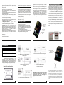
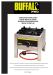
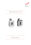
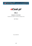
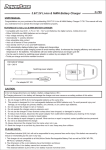
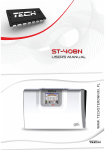
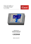
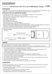
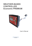
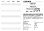
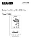
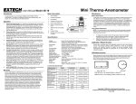
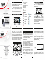
I. Use
User’s manual
ST-290
ST-290 room regulator is a multi-purpose device used for
controlling the heating device (e.g. gas-fired boiler, oil-fired
boiler, electric boiler or CH boiler controller).
The main aim of this regulator is to maintain the set
temperature in the room. For this purpose
it sends the signal (contact opening) to the heating
device with a command to heat up the room to desired
temperature. The regulator offers weekly control program,
day-time/night-time mode and manual mode. A wireless
version of the regulator is also available, with an additional
signal receiver to be installed near the CH boiler controller.
1 Active mode of operation
- weekly control
- manual
- day-time / night-time
2 Current room temperature
3 Heating-up signal
4 Day of the week
5 External temperature
6 Set room temperature
7 Time
8 Battery level
9 Buttons for introducing changes
III.Principle of operation
The device is controlled using the following buttons:
<right>, <left>, <+>, <-> and <OK>. In the main screen
view the user can preview the current day of the week, clock,
current and pre-set room temperatures, controller operation
mode and battery level.
Graphic icons
Room regulator
Time settings
Select weekly
program
4
Night-time from...
Day-time
temperature
5
Day-time from...
Night-time
temperature
II.Description
.
of graphic symbols
3
2
Weekly program
settings
6
Hysteresis
Night-time
temperature active
7
1
The basic screen view enables the user to quickly
change the operation mode using <left> and <right>
buttons (weekly control)... program and day/night program
respectively).
If the room temperature is too low,
icon is flashing.
When the pre-set temperature is reached, the icon lights up
permanently. If the pre-set temperature is changed quickly
with <+> and <-> buttons, the operation mode will
automatically switch to manual and it will remain active until
the next pre-programmed temperature change (according
to weekly or day/night program).
Press and hold <OK> for about 1 second to enter the
menu for any particular setting and select the function to be
edited using <right> or <left> buttons.
.
Select channel
Day-time
temperature active
8
9
2
1
When previewing the menu, only the editable or
modifiable functions are displayed.Particular settings of
the editable items can be changed using <+> and <->
buttons. After the setting has been changed, press <left>
button to go to the next parameter and confirm the setting.
Once the editing of all parameters has been completed,
press <OK> and hold it for about 1 second. The
controller will return to the main view. Each setting may be
edited in a similar way (except for weekly control program
settings where the user has to confirm the access to the
settings with <OK> button while icon is flashing.....)
IV. Description of controller functions
In order to edit or modify any particular setting, press
<MENU> button and hold it for approx.1 second. The
function being edited will be indicated with a flashing icon (all
the remaining iconswill be inactive) until the selection is
accepted by pressing the button. (To maintain the order of
the editable functions presented below, the selection has
to be accepted by pressing <left>button).
The first item to be edited after entering the menu
(by pressing <MENU> button) is the
current day of the week:
1.Day of the week – set the current day of the week by
pressing <+> and <->. Press <left> button to confirm the
setting and jump to the next item to be edited.
2. Clock – set the time by using <+> and <-> buttons to set
the hour. Press <left> button to confirm and then set the
minutes. Press <left> button to confirm the setting and
jump to the next item to be edited.
NOTE! Setting the day and time is necessary for proper
operation of the weekly and day/night modes.
Weekly
control
+
3.'Night from...' setting- press <+> and <-> buttons to set
the time when the controller should switch to night-time
mode.
Press
<left> button to confirm the setting
(applicable to day/night program only).
OK
Manual
change
of set temp.
Manual Day-time/night
change -time program
of set temp.
MENU
4
4.'Day from...' setting- press <+> and <-> buttons to set
the time when the controller should switch to day-time
mode. Press <left> button to confirm the setting (applicable
to day/night program only).
5
3
5.Configuration of particular weekly control programs
– press <OK> to edit this setting. First select the number of
the weekly control program which you want to edit by
pressing <OK.> The controller enables the user to program
nine various programs divided into three main groups:
•programs 1÷3 – day/night settings are introduced for all
days of the week (Monday – Sunday),
•programs 4÷6 – day/night settings are introduced for
working days first (Monday – Friday) and then for the
weekend (Saturday - Sunday),
•programs 7÷9 – day/night settings are introduced for each
day of the week separately.
number
of the program
being edited.
Once the desired program number is displayed on the
screen, the program can be edited.
The user selects the day of the week for which the
temperature settings are to be changed, using <left> and
<right> buttons.
6
The next step involves assigning temperature values to
particular times of the day by pressing <-> button (to assign
night-time temperature to the selected time) or <+> (to
assign day-time
temperature to the selected time). The program will
automatically move on to the next time value.
After the program is configured, it is automatically saved in
the controller memory.
In order for the regulator to switch to the selected program,
select the desired program
number by pressing <OK> button and holding it for about
3 seconds. The controller will return to the main screen and
the selected program will be activated.
6. Set day-time temperature - using <+> and <-> buttons
the user may define the set day-time temperature. In order
to confirm the setting, press <right> button.
8. Set night-time temperature - using <+> and <->
buttons the user may define the set night-time temperature.
In order to confirm the setting, press <right> button.
9. Hysteresis – using <+>and <-> buttons the user may
adjust the hysteresis value. Room temperature hysteresis
defines pre-set temperature tolerance in order to prevent
undesired oscillation in case of small temperature
fluctuation (within the range of 0,2÷ 4°C)
Example: when the pre-set temperature value is 23°C and
hysteresis value is set to 1°C, the regulator will indicate
insufficient room temperature only after the temperature
drops to 22°C.
Press <right> button in order to confirm the set value and
move on to the next function.
10. Channel selection – this function enables the user to
choose the channel of communication. Press <OK> button
in order to confirm the setting. .
V.Restoring factory settings
The user may restore factory settings from the main screen
view by pressing both <right> and <left> buttons and
holding for about 3 seconds. The controller will confirm the
restoration of factory settings by displaying 'space' lines <-:-->.
Once the factory settings are restored, the following settings
will be deleted (or restored to default):
➢all weekly control settings,
➢day-time/night-time temperature,
➢'day/night from …' setting,
The default channel of communication set in the room
regulator is 0. The user may easily change to a different
channel if the current one is used by another device. In
order to introduce changes, press channel change button
on the receiver for about 10 seconds until the first green
control lamp lights up. Then, change the channel in the
room regulator by pressing <OK> and <up> button. Select
the desired channel using <+> and <–> buttons and press
and hold <OK> button for about 1 second. The green
control light of the receiver should go out. Pressing <left>
or <right> buttons to exit the editing mode will not cause
channel change.
VI.Wireless regulator
ST-290v2 regulator enables wireless communication with
the signal receiver, which may be
connected to the heating device or CH boiler controller.
The receiver is equipped with the following control lights:
•green 1 – it indicates data reception and it lights up when
the channel is being changed.
•red – it indicates operation of the receiver.
•green 2 – it lights up when the room temperature is lower
than the preset value – the heating device is on.
Green control
light no. 1
ST-290v2 room temperature regulator may be optionally
equipped with an external temperature sensor. The sensor
should be installed in a shaded place to avoid any weatherrelated influences. Current external temperature value is
sent to the regulator every few minutes and it is displayed on
the main screen, next to the symbol:
The external sensor communicates with the regulator
using radio waves. Both devices are pre-set to use channel
0 for communication but this setting may be easily changed
(if the default channel is used by other devices). In order to
change the channel, press and hold the channel change
button. After the control light flashes twice, the process of
channel change has been initiated. Hold the button and wait
until the light starts flashing again. The number of flashes
corresponds to the channel number (1 flash – channel 1; 5
flashes – channel 5). After the desired channel has been
selected, release the button. In order to return to channel 0,
repeat the procedure releasing the button after the first two
flashes.
Red control
light
Green control
light no. 2
control
light
Channel change
button
9
8
7
VII.External temperature sensor
Channel
change
button
10
VIII.Installation
Technical data:
Range of room temperature setting
10oC : 35oC
Supply voltage
baterie 2xAA, 1.5V
Measurement error
+/- 1OC
Load carrying capacity of the contact
1A/230V/50Hz
Operating temperature
5oC : 50oC
Overall dimensions
135x95x24 [mm]
Heating
device
above 1A
Heating
device
Connection of ST-290 controller to the heating device
above 1 A.
Direct connection of ST-290 controller to
the heating device.
Regulator pokojowy ST-290 połączony jest ze
sterownikiem kotła lub urządzeniem grzewczym (np
piecem gazowym lub olejowym) za pomocą dwużyłowego
kabla komunikacyjnego. Połączenie przewodów obu
urządzeń przedstawiają poniższe przykładowe schematy.
CH boiler
controller
Heating
device
Connection of ST-290 controller to CH
boiler controller.
Spacing of mounting holes.
Socket for connecting
the two-wire
communication cable.
Connection of ST-290 controller to
three-phase heating device.
NOTE: When connecting the wireless receiver, use the
wiring diagrams presented above - the two-wire
communication cable should be plugged into
appropriate sockets in the receiver.
Heating device
max 1 A
Connection of ST-290 controller to the
heating device up to 1 A.
11
12
13
We are committed to protecting the environment. Manufacturing
electronic devices imposes an obligation of providing for
environmentally safe disposal of used electronic components and
devices. Hence, we have been entered into a register kept by the
Inspection For Environmental Protection. The crossed-out bin symbol
on a product means that the product may not be disposed of to
household waste containers. Recycling of wastes helps to protect the
environment. The user is obliged to transfer their used equipment to a
collection point where all electric and electronic components will be
recycled.
14