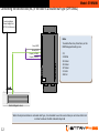
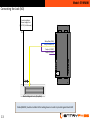
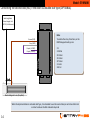
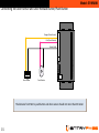
1
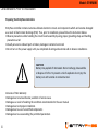
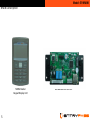
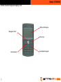
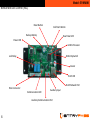
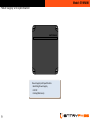
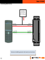
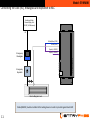
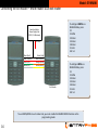
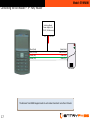
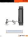
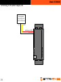
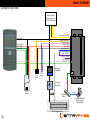
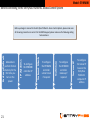
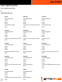
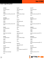
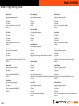
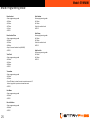
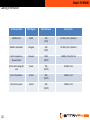
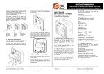
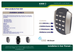
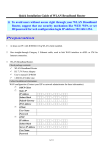
Wiring Guide
EP.NMINI
Version 1.02
1
Last Updated: 14-10-2014
Model: EP.NMINI
Note:
See http://www.entrypass.net/ for updates, revisions, and download the latest installation manual
There are currently 2 version of EntryPass Platform1 Access Control System available for different card
number system
1) EntryPass Platform1 Access Control System (6 Digit Card Number System) cater for 6 digit card
number installation
2)EntryPass Platform1 Access Control System (10 Digit Card Number System) cater for 10 digit card
number installation
For EntryPass Platform1 Access Control System to work correctly, both control panel and software MUST
be using the same card number system
This software installation manual might be updated without prior notice
Please refer to separate EntryPass Platform1 User Manual for detail operation help. The Official
EntryPass Platform1 User Manual can be downloaded from our website under “Download” section
2
Model: EP.NMINI
Before you begin
Technical Support
If you cannot find the answer to your question in this manual or in the Help files, we recommend you
contact your system installer. Your installer is familiar with your system configuration and should be able
to answer any of your questions.
Should you need additional information, please call our Technical Support Help desk, Monday to Friday
9:00 AM to 6:00 PM (GMT +8:00)
Method Details
Phone + 60 (3) - 8068 1929
Fax + 60 (3) - 8068 1922
Internet www.entrypass.net
Email [email protected]
3
Model: EP.NMINI
Considerations Prior to Installation
Preparing Your EntryPass Controllers
EntryPass controller contains numerous delicate electronic circuits and components which can become damaged
as a result of electrostatic discharge (ESD). Thus, prior to installation, please follow the instruction below:
•Observe precautions while handling the circuit board assembly by using proper grounding straps and handling
precautions at all
•Visually ensure no onboard parts is broken, damage or contains burn mark
•Do not turn on the power supply until you completed all wiring and external add on devices installations
CAUTION
Battery may explode if mistreated. Do not recharge, disassemble
or dispose of in fire. To prevent a risk of explosion do not pry the
battery out with a metal or conductive tool.
Instances of Non-Warranty
•Damage due to natural disaster, accident or human cause.
•Damage as a result of violating the conditions recommended in the user manual
•Damage due to improper installation
•Damage due to use of uncertified components
•Damage due to use exceeding the permitted parameters
4
Model: EP.NMINI
NMiNi Description
NMiNi Reader
Keypad Display Unit
5
Networked Lock Control
Model: EP.NMINI
NMiNi Color Description
NMiNi Reader Color Description
Red
Black
Pink
Black
Blue
Brown
White
Green
Orange
Yellow
Grey
Purple
Green
White
6
: +12VDC
: GND / 0VDC
: Not In Used
: GND / 0VDC
: Not In Used
: Not In Used
: Exit Reader D1
: Exit Reader DO
: Not In Used
: Not In Used
: Not In Used
: Not In Used
: RS232 RX Separated
: RS232 TX Separated
Networked Lock Control (NLC) Description
Red / Yellow
Black
Orange
Yellow
Blue
Pink
Red
Black
Grey / Yellow
White / Blue
White
Brown
Grey
Green
Purple
Purple
: +12VDC
: GND / 0VDC
: Door Sensor
: Not In Used
: Not In Used
: Push Button
: +12VDC
: GND / 0VDC
: NO1
: CM1
: NC1
: NO2
: CM2
: NC2
: +12Vdc Lock
: +12Vdc Lock
Green
White
: RS232 TX Separated
: RS232 RX Separated
Model: EP.NMINI
NMiNi Reader Keypad Display Unit
White LCD Display
Navigation Pad
Enter Key
LED Indicator
7
Numbered Keypad
Model: EP.NMINI
Networked Lock Control (NLC)
Reset Button
Cold Start Button
Backup Battery
Heart Beat LED
Power LED
32-Bits Processor
Lock Relay
8-Bits Dip Switch
Buzzer
RJ-45 LED
RJ-45 Network Port
Wire Connector
Communication LED
Auxiliary Input
Auxiliary Communication Port
8
Model: EP.NMINI
Power Supply Unit Specification
ENTRYPASS
Power Supply Unit Specification:
• Switching Power Supply
• 12V DC
• 3 Amp (Minimum)
9
Model: EP.NMINI
Connecting NMINI to NLC
Switching Mode
Power Supply Unit
(12V DC, 3A Minimum)
0V
+12 VDC
Black (Gnd)
Red (12+VDC)
Green (RS 232)
White (RS 232)
Green (RS 232)
White (RS 232)
The distance from NMINI keypad reader to NLC should not more than 30 meter
10
ENTRYPASS
Black (Gnd)
Red (+12VDC)
Model: EP.NMINI
Connecting the Lock (NC), Breakglass and Keyswitch to NLC
Switching Mode
Power Supply Unit
(12V DC, 3A Minimum)
0V
White/Blue (CM1)
White (NC1)
Purple (+12VDC)
Purple (+12VDC)
Emergency
Breakglass
ENTRYPASS
Emergency
Keyswitch
+
-
+
Electro-Magnetic Lock
Diode(1N4002) must be installed at the locking devices in order to protect against back EMF
11
Model: EP.NMINI
Connecting the second lock (NC) if the door is a double leaf type (OPTIONAL)
Switching Mode
Power Supply Unit
(12V DC, 3A Minimum)
0V
Note:
To enable the relay 2 function, on the
NMINI keypad reader, press:
Grey (CM2)
Green (NC2)
Purple (+12VDC)
Purple (+12VDC)
ENTRYPASS
+
-
•F1
•123456
•01 Enter
•01 Enter
•07 Enter
•1 Enter
•ESC x3
+
Electro-Magnetic Lock
When the implementation is on double leaf type, it is advisable to use the second relay to control another lock
in order to reduce the NLC onboard relay load
12
Model: EP.NMINI
Connecting the Lock (NO)
Switching Mode
Power Supply Unit
(12V DC, 3A Minimum)
0V
White/Blue (CM1)
Grey/Yellow (NO1)
Purple (+12VDC)
Purple (+12VDC)
ENTRYPASS
+
-
+
Electro-Magnetic Lock (Drop Bolt)
Diode(1N4002) must be installed at the locking devices in order to protect against back EMF
13
Model: EP.NMINI
Connecting the second lock (NO) if the door is a double leaf type (OPTIONAL)
Switching Mode
Power Supply Unit
(12V DC, 3A Minimum)
0V
Note:
To enable the relay 2 function, on the
NMINI keypad reader, press:
Brown (NO2)
Grey (CM2)
Purple (+12VDC)
Purple (+12VDC)
ENTRYPASS
+
-
•F1
•123456
•01 Enter
•01 Enter
•07 Enter
•1 Enter
•ESC x3
+
Electro-Magnetic Lock (Drop Bolt)
When the implementation is on double leaf type, it is advisable to use the second relay to control another lock
in order to reduce the NLC onboard relay load
14
Model: EP.NMINI
Connecting the Door Sensor and Door Release Button/Push Button
Orange (Door Sensor)
Pink (Push Button)
Black (Gnd)
ENTRYPASS
Door Sensor
Push Button
The distance from NLC to push button and door sensor should not more than 30 meter
15
Model: EP.NMINI
Connecting the Exit Reader – NMINI reader as an exit reader
To configure NMINI as a
READER Mode, press:
•F1
•123456
•01 Enter
•01 Enter
•04 Enter
•1 Enter
•ESC x3
Switching Mode
Power Supply Unit
(12V DC, 3A Minimum)
0V
Black (Gnd)
Red (+12VDC)
Green (D0)
White (D1)
+12 VDC
Black (Gnd)
Red (+12VDC)
Orange (RCLK)
Yellow (RDAT)
Exit Reader
To configure MINI as a
READER Mode, press:
•F1
•123456
•01 Enter
•01 Enter
•05 Enter
•1 Enter
•ESC x3
To use NMINI/MINI on exit reader side, you must enable the READER MODE function on the
programming mode
16
Model: EP.NMINI
Connecting the Exit Reader – 3rd Party Reader
Switching Mode
Power Supply Unit
(12V DC, 3A Minimum)
0V
Black (Gnd)
Red (+12VDC)
Green (D0)
White (D1)
+12 VDC
Black (Gnd)
Red (+12VDC)
Green (D0)
White (D1)
Exit Reader
The distance from NMINI keypad reader to exit reader should not more than 10 meter
17
Model: EP.NMINI
Connecting to the PC (EntryPass Platform1 Access Control System)
EntryPass Platform1 Access
Control System
Network Switch
The distance from NLC to network switch should not more than 150 meter
18
ENTRYPASS
Cat-5
Cat-5
Model: EP.NMINI
Connecting to the power supply unit
Switching Mode
Power Supply Unit
(12V DC, 3A Minimum)
0V
+12 VDC
Red/Yellow (+12VDC)
Black (Gnd)
ENTRYPASS
19
Model: EP.NMINI
Complete overview
Switching Mode
Power Supply Unit
(12V DC, 3A Minimum)
0V
+12 VDC
Red/Yellow (+12VDC)
Black (Gnd)
Orange (Door Sensor)
Pink (Push Button)
Red (+12VDC)
Black (Gnd)
White/Blue (CM1)
White (NC1)
Purple (+12VDC)
Purple (+12VDC)
Black (Gnd)
Red (+12VDC)
Green (D0)
White (D1)
ENTRYPASS
White (RS 232)
Green (RS 232)
Emergency
Breakglass
Push
Button
Cat - 5 e
Door
Sensor
Emergency
Keyswitch
Exit
Reader
+
-
-
Network
Switch
+
Electro-Magnetic Lock
20
Cat - 5e
EntryPass Platform1
Server Access
Control System
Model: EP.NMINI
Before connecting to the EntryPass Platform1 Access Control System
21
To configure
the EP.NMINI
controller
Gateway if
required
Server IP
To configure
the EP.NMINI
controller
subnet mask
if required
Gateway
To configure
the EP.NMINI
controller IP
address
Subnet Mask
Advisable to
perform format
memory for the
first time you
turn on the
power
IP Address
Factory Default
Before you begin to connect to the EntryPass Platform1 Access Control System, please make sure
all the wiring connection is correct. On the NMINI keypad, please make sure the following setting
has been done:
To configure
the Server IP
base on the
EntryPass
Platform1
computer IP
address
Model: EP.NMINI
NMINI Programming Mode
To enter programming mode, press:
•F1
•123456 (default admin pin)
22
Admin Pin
•Enter programming mode
•01 Enter
•01 Enter
•01 Enter
•Key in new admin pin (6 digits)
•ESC X3
MiNi Location
•Enter programming mode
•01 Enter
•01 Enter
•06 Enter
•1 Enter (Press 1 to set it ON or press 0 to set it OFF)
•ESC X3
Port Number
•Enter programming mode
•01 Enter
•01 Enter
•11 Enter
•Key in the new Port number
•ESC X3
Security Level
•Enter programming mode
•01 Enter
•01 Enter
•02 Enter
•1 Enter (Press 1 to set it ON or press 0 to set it OFF)
•ESC X3
Relay2 Function
•Enter programming mode
•01 Enter
•01 Enter
•07 Enter
•1 Enter (Press 1 to set it ON or pres 0 to set it OFF)
•ESC X3
Server IP
•Enter programming mode
•01 Enter
•01 Enter
•12 Enter
•Key in the new Server IP
•ESC X3
Unit Address
•Enter programming mode
•01 Enter
•01 Enter
•03 Enter
•Key in the new unit address (000 – 254 sets)
•ESC X3
IP Address
•Enter programming mode
•01 Enter
•01 Enter
•08 Enter
•Key in the new IP address
•ESC X3
Disable Wizard
•Enter programming mode
•01 Enter
•01 Enter
•13 Enter
•1 Enter (Press 1 to set it ON or press 0 to set it OFF)
•ESC X3
Reader Mode
•Enter programming mode
•01 Enter
•01 Enter
•04 Enter
•1 Enter (Press 1 to set it ON or press 0 to set it OFF)
•ESC X3
Subnet Mask
•Enter programming mode
•01 Enter
•01 Enter
•09 Enter
•Key in the new Subnet Mask
•ESC X3
Ethernet Speed
•Enter programming mode
•01 Enter
•01 Enter
•14 Enter
•Press 1 to set to 100Mbps (default) or press 0 to set to 10
Mbps
•ESC X3
Standalone
•Enter programming mode
•01 Enter
•01 Enter
•05 Enter
•1 Enter (Press 1 to set it ON or press 0 to set it OFF)
•ESC X3
Gateway
•Enter programming mode
•01 Enter
•01 Enter
•10 Enter
•Key in the new Gateway
•ESC X3
Model: EP.NMINI
NMINI Programming Mode
Inhibit Mode
•Enter programming mode
•01 Enter
•02 Enter
•01 Enter
•1 Enter (Press 1 to set it ON or press 0 to set it OFF)
•ESC X3
Security Mode
•Enter programming mode
•01 Enter
•02 Enter
•02 Enter
•0 Enter (Press 1 to set it ON or press 0 to set it OFF)
•ESC X3
Site Code 1
•Enter programming mode
•01 Enter
•02 Enter
•03 Enter
•Key in the new site code (4 digits)
•ESC X3
Site Code 2
•Enter programming mode
•01 Enter
•02 Enter
•04 Enter
•Key in the new site code (4 digits)
•ESC X3
Site Code 3
•Enter programming mode
•01 Enter
•02 Enter
•05 Enter
•Key in the new site code (4 digits)
•ESC X3
23
Door Pin 1
•Enter programming mode
•01 Enter
•02 Enter
•06 Enter
•Key in the new door pin (6 digits)
•09 Enter
•001
•ESC X3
Door Pin 2
•Enter programming mode
•01 Enter
•02 Enter
•07 Enter
•Key in the new door pin (6 digits)
•10 Enter
•001
•ESC X3
Door Pin 3
•Enter programming mode
•01 Enter
•02 Enter
•08 Enter
•Key in the new door pin (6 digits)
•11 Enter
•001
•ESC X3
Door Pin 1 Tz
•Enter programming mode
•01 Enter
•02 Enter
•09 Enter
•Key in the new door pin timezone (000 – 255)
•ESC X3
Door Pin 2 Tz
•Enter programming mode
•01 Enter
•02 Enter
•10 Enter
•Key in the new door pin timezone (000 – 255)
•ESC X3
Door Pin 3 Tz
•Enter programming mode
•01 Enter
•02 Enter
•11 Enter
•Key in the new door pin timezone (000 – 255)
•ESC X3
Exit Button Tz
•Enter programming mode
•01 Enter
•02 Enter
•12 Enter
•Key in the new exit button timezone (000 – 255)
•ESC X3
Auto Release Tz
•Enter programming mode
•01 Enter
•02 Enter
•13 Enter
•Key in the new auto release timezone (000 – 255)
•ESC X3
Release Time
•Enter programming mode
•01 Enter
•02 Enter
•14 Enter
•Key in the new release time (00 – 99)
•ESC X3
Model: EP.NMINI
NMINI Programming Mode
Open Time
•Enter programming mode
•01 Enter
•02 Enter
•15 Enter
•Key in the new open time (00 – 99)
•ESC X3
Pin Trials
•Enter programming mode
•01 Enter
•02 Enter
•16 Enter
•Key in the new pin trials (00 – 09)
•ESC X3
Card+Pin Tz
•Enter programming mode
•01 Enter
•02 Enter
•17 Enter
•Key in the new card+pin timezone (000 – 255)
•ESC X3
Date Setting
•Enter programming mode
•01 Enter
•03 Enter
•Key in the new date (DDMMYY)
•ESC X2
Time Setting
•Enter programming mode
•01 Enter
•04 Enter
•Key in the new time (HHMMSS)
•ESC X2
24
Reset Password
•Enter programming mode
•01 Enter
•05 Enter
•01 Enter
•ESC X2
Reset Door Data
•Enter programming mode
•01 Enter
•05 Enter
•02 Enter
•ESC X2
Format Memory
•Enter programming mode
•01 Enter
•05 Enter
•03 Enter
•When finish formatting, a beep sound will be heard
•ESC X2
Factory Default
•Enter programming mode
•01 Enter
•05 Enter
•04 Enter
•1 Enter
•Key in the current admin pin
•When finish performing factory default, a beep sound will
be heard
Install Card
•Enter programming mode
•02 Enter
•01 Enter
•01 Enter
•Key in the card number (6 digits)
•ESC X3
Delete Card
•Enter programming mode
•02 Enter
•01 Enter
•02 Enter
•Key in the card number (6 digits)
•ESC X3
View Card
•Enter programming mode
•02 Enter
•01 Enter
•03 Enter
•Key in the card number (6 digits)
•ESC X4
Quick Install
•Enter programming mode
•02 Enter
•01 Enter
•04 Enter
•Flash all the cards to be installed (card by card)
•ESC X4
Quick Delete
•Enter programming mode
•02 Enter
•01 Enter
•05 Enter
•Flash all the cards to be deleted (card by card)
•ESC X4
Reset Card Pin
•Enter programming mode
•02 Enter
•01 Enter
•06 Enter
•Key in the card number that need to perform pin reset
•ESC X3
Model: EP.NMINI
NMINI Programming Mode
Reset Lockout
•Enter programming mode
•02 Enter
•01 Enter
•07 Enter
•1 Enter
•ESC X3
Reset Lockout Time
•Enter programming mode
•02 Enter
•01 Enter
•08 Enter
•Key in the reset lockout time (HHMM)
•ESC X3
Total Card
•Enter programming mode
•02 Enter
•01 Enter
•09 Enter
•ESC X3
Transaction
•Enter programming mode
•02 Enter
•02 Enter
•Press F3 button to view the next transaction event or F1
button to go back to previous transaction event
•ESC X3
Info Menu
•Enter programming mode
•03 Enter
•ESC X2
Extra Info Menu
•Enter programming mode
•04 Enter
•ESC X2
25
Card Number
•Enter programming mode
•05 Enter
•01 Enter
•Flash the card to check
•ESC X3
Card Binary
•Enter programming mode
•05 Enter
•02 Enter
•Flash the card to check
•ESC X3
Help Line Info
•Enter programming mode
•05 Enter
•03 Enter
•ESC X3
Model: EP.NMINI
Cabling Information
26
Communication
Data Signal
Max Distance
Description
NMINI to NLC
RS232
10m
(30 ft)
22 AWG, 2 Pairs, Shielded
NMINI to Exit Reader
Wiegand
10m
(30 ft)
22 AWG, 2 Pairs, Shielded
NLC to Computer or
Network Switch
Network
100m
(300 ft)
24AWG, 4 Pairs (Cat 5e)
NLC to Electro-Magnetic
Lock
Power
30m
(100 ft)
18 AWG, 1 Pair
NLC to Push Button
Contact
30m
(100 ft)
22AWG, 1 Pair
NLC to Door Sensor
Contact
30m
(100 ft)
22AWG, 1 Pair