1
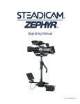
USER MANUAL
www.QIMAGING.com
optiMOS USER MANUAL
Applicability
This document applies to the optiMOS camera. For the latest updates, please visit www.qimaging.com.
Notice of Copyright
Copyright © 2014 Quantitative Imaging Corporation. All rights reserved. Unauthorized duplication of this
document is prohibited.
Trademarks and Proprietary Names
optiMOS™ is a trademark of QImaging. QImaging® and PVCAM® are registered trademarks of Roper Scientific,
Inc. Product names mentioned in this document may be trademarks or registered trademarks of QImaging or
other hardware, software or service providers, and are used herein for identification purposes only. Microsoft®
and Windows® are registered trademarks in the U.S. and other countries of Microsoft Corporation and are
used herein for identification purposes only.
QImaging Corporation Address Information
19535 56th Avenue,
Suite 101
Surrey, BC, Canada V3S 6K3
604.530.5800
www.qimaging.com
QImaging Technical Support
Technical support is available to all registered users of QImaging products from 9am to 5pm Pacific
Standard Time.
[email protected]
800.874.9789
http://www.qimaging.com/support/contact
www.qimaging.com
©2014 QImaging. All rights reserved. QI_OPTIMOS_UM_Rev_A1
optiMOS USER MANUAL
QIMAGING LIMITED WARRANTY
Standard Product Warranty Plan
A Standard Product Warranty Plan is included with every QImaging camera purchase. This Warranty Plan
includes parts and labor for two full years (starting from the shipping date of the camera). The Standard
Product Warranty Plan is provided on all new and used equipment, including retired demonstration cameras.
Extended Product Warranty Plan
Extended Product Warranty Plans are conveniently priced and very easy to purchase. Available for all QImaging
cameras, the Extended Product Warranty Plan includes parts and labor, and is available in one-year increments
up to five years.
When you purchase an Extended Product Warranty Plan from QImaging, you are assured of our commitment
to minimizing down times. Your needs are our top priority and QImaging responds immediately. The QImaging
Service and Support team is focused on expediting all customer requests to provide a fast and complete
solution.
QImaging also offers on-site training as well as online operational training programs. These programs are
designed to get you up and running with your new camera quickly and efficiently.
Contact a QImaging Representative to learn more about Extended Product Warranty Plan options.
www.qimaging.com
©2014 QImaging. All rights reserved. QI_OPTIMOS_UM_Rev_A1
optiMOS USER MANUAL
optiMOS CERTIFICATE OF CONFORMITY
www.qimaging.com
©2014 QImaging. All rights reserved. QI_OPTIMOS_UM_Rev_A1
optiMOS USER MANUAL
Table of Contents
INTRODUCTION .............................................................................................................. 1
System Components ......................................................................................................... 1
Precautions......................................................................................................................... 2
Environmental Conditions for Operation and Storage.......................................................... 2
Microscopes, Lenses, Tripods............................................................................................... 2
Cleaning............................................................................................................................. 3
Repair................................................................................................................................. 3
INSTALLATION ................................................................................................................ 4
Host Computer Requirements............................................................................................. 4
Camera Power Requirements.............................................................................................. 5
Install the High Speed PCIe Board........................................................................................ 5
Install the Camera Driver..................................................................................................... 6
Connect the Camera........................................................................................................... 7
USING YOUR optiMOS CAMERA.................................................................................... 9
Imaging Software................................................................................................................ 9
Basic Camera Parameters.................................................................................................... 9
Exposure Time..................................................................................................................... 9
Rolling Shutter.................................................................................................................... 9
Gain ................................................................................................................................. 11
Clearing Mode.................................................................................................................. 11
Regions of Interest (ROI).................................................................................................... 13
Digital Binning.................................................................................................................. 13
Device Synchronization..................................................................................................... 14
Hardware Triggering Modes.............................................................................................. 14
Expose Out Behaviors ....................................................................................................... 15
TROUBLESHOOTING ..................................................................................................... 18
Resolving Problems with the Camera................................................................................. 18
Unresolved Problems - Contacting QImaging Support ....................................................... 20
SPECIFICATIONS ............................................................................................................ 21
www.qimaging.com
©2014 QImaging. All rights reserved. QI_OPTIMOS_UM_Rev_A1
optiMOS USER MANUAL
CHAPTER 1
INTRODUCTION
optiMOS from QImaging is the live cell
replacement to CCD cameras. Featuring
faster frame rates and lower noise,
optiMOS was designed as the budget
friendly alternative that avoids complex
data management in the PC. Capable
of streaming 100fps with <2e- of read
noise, optiMOS delivers 10x the temporal
resolution of CCD cameras without trading
off on resolution or sensitivity. Offered as
the affordable sCMOS solution, optiMOS
brings the advantages of low noise and
high speed imaging to a broader range of
cell biology applications.
This manual describes the installation
and configuration procedures for your
new optiMOS Scientific CMOS camera.
Descriptions of the recommended optiMOS
camera settings are also included.
System Components
Your new camera system includes:
■■
optiMOS Scientific CMOS camera
■■
High Speed PCIex4 Data Card
■■
9V 8.33A Power Supply
■■
International Power Cord Set
■■
3 Meter High Speed Data Cable
■■
Black Lens Cap
■■
USB flash drive: PVCAM driver, manual, datasheet, training materials
www.qimaging.com
©2014 QImaging. All rights reserved. QI_OPTIMOS_UM_Rev_A1
1
optiMOS USER MANUAL
Precautions
The sCMOS sensor and other optiMOS camera system electronics are extremely sensitive to electrostatic
discharge (ESD). To avoid permanently damaging the system, please observe the following precautions:
■■
If you are using high-voltage equipment (such as an arc lamp) with your camera system, be sure to
turn the camera power on last and power the camera off first.
■■
Never connect or disconnect any cable while the camera system is powered on.
■■
Although you should turn off the camera’s power supply before disconnecting any camera system
cable, you do not need to power off your computer to detach the cables.
■■
Use caution when triggering high-current switching devices (such as an arc lamp) near your
system. The sCMOS can be permanently damaged by transient voltage spikes. If electrically noisy
devices are present, an isolated, conditioned power line or dedicated isolation transformer is highly
recommended.
■■
Always leave at least one inch of space around the camera housing.
■■
Never open the camera. There are no user-serviceable parts inside the optiMOS camera. Opening
the camera voids the warranty.
■■
Use only the integrated data interface, cables, and power supply designated for this camera system.
Using non-optiMOS cables or power supplies may result in permanent damage to your system.
■■
Do not use a C-mount lens that has optics that extend behind the flange of the lens.
Environmental Conditions for Operation and Storage
Your optiMOS camera system should be operated in a clean, dry environment. The camera system’s ambient
operating temperature is 0°C to 20°C with 80% relative humidity, noncondensing.
Store the optiMOS camera system in its original containers. To protect the system from excessive heat, cold,
and moisture, store at an ambient temperature between -20°C and 60°C with a relative humidity of 0% to
90%, noncondensing.
Microscopes, Lenses, Tripods
optiMOS has a standard threaded video mount and can be mounted to any microscope that accepts a standard
C-mount adapter. The camera also allows you to install any lens that is compatible with a standard threaded
video mount as long as its optics do not extend behind the flange of the lens.
The optiMOS camera can be mounted to a tripod using the tripod mounting attachment located on the top
and bottom of the camera. See the Specifications chapter for more information.
www.qimaging.com
©2014 QImaging. All rights reserved. QI_OPTIMOS_UM_Rev_A1
2
optiMOS USER MANUAL
Cleaning
Clean the exterior surfaces of the camera with a dry, lint-free cloth. To remove stains, contact QImaging
Support. To clean the camera’s imaging window, use only a filtered compressed-air source. Handheld cans are
not recommended, as they may spray propellant onto the window. Do not touch the window.
Repair
The optiMOS camera system contains no user-serviceable parts. Repairs must be completed by QImaging.
Should your camera system need repair, contact QImaging Support. Please save the original packing materials
so you can safely ship the camera system to another location or return it for repairs if necessary.
IMPORTANT: DO NOT OPEN the camera. Opening the optiMOS camera voids the warranty.
www.qimaging.com
©2014 QImaging. All rights reserved. QI_OPTIMOS_UM_Rev_A1
3
optiMOS USER MANUAL
CHAPTER 2
INSTALLATION
This chapter will detail the proper installation of your optiMOS camera. In order to install and use the camera,
the following items are required:
■■
optiMOS camera (supplied)
■■
High Speed Data Cable (supplied)
■■
High Speed PCIex4 Data Card
■■
9V 8.33A power supply (supplied)
■■
USB “installer” flash drive (supplied)
■■
110V/220V power connection
■■
A PC that meets the host computer requirements
Host Computer Requirements
The host computer for your optiMOS camera must include at a minimum:
■■
Windows 7 or Windows 8 operating system (64 bits)
■■
≥3.0GHz Intel processor: either Xeon or Core i7
■■
≥8GB RAM, 1600MHz DDR3 Non-ECC
■■
≥250GB serial ATA (SATA) HDD and/or >64GB solid state drive (SDD) for
high-speed imaging and storage
■■
≥256MB slot-based ATI/NVIDIA video graphics card
(i.e., not an “onboard/integrated graphics” adapter)
■■
≥600W power supply
■■
USB drive or internet access to install the driver
■■
At least 1 available PCIex4 slot
NOTE: Minimum requirements as of June 2014. Supported computer systems will change as new cameras,
computer hardware, and operating systems are introduced and older models become obsolete. For current
information on recommended computer specifications, please visit: http://www.qimaging.com/support/
recommended-computer-specifications.php
www.qimaging.com
©2014 QImaging. All rights reserved. QI_OPTIMOS_UM_Rev_A1
4
optiMOS USER MANUAL
Camera Power Requirements
■■
9V DC, 8.33A (maximum)
A power supply for use with your optiMOS camera has been provided by QImaging.
IMPORTANT: Follow the below steps in order.
DO NOT install the driver until the PCIe card is installed.
1. Install the High Speed PCIe Board
Because of the 100 fps frame rate with a 16-bit output, the data rate of the optiMOS is significantly higher
than traditional CCD cameras. At 420MB/s the optiMOS requires a more powerful data transfer interface than
the frequently used USB or FireWire interfaces. For that reason, the optiMOS is supplied with a proprietary High
Speed PCIe card that is capable of sustaining the bandwidth requirements of the camera.
Before doing anything with the camera, first install this interface card with the following steps:
1. Shut down desktop PC
2. Unplug desktop power supply
3. Open the side of the computer to access the PCI and PCIe slots
www.qimaging.com
©2014 QImaging. All rights reserved. QI_OPTIMOS_UM_Rev_A1
5
optiMOS USER MANUAL
4. Locate an available 4 channel or higher PCIe slot (marked x4). Refer to the PC’s documentation or
side covers for motherboard’s PCIe slots information.
5. Holding the optiMOS PCIe card (careful not to touch the board components or PCIe bridge pins)
insert with the proper orientation into the open slot. The card should slide into place with minimal
resistance and snap when fully inserted.
6. Once installed, close computer case, plug in power supply and power on the desktop. The
computer is now ready to install the camera’s drivers.
2. Install the Camera Driver
In order for optiMOS to communicate with the host PC, the camera’s device drivers (PVCAM) must first be
installed. Before connecting the camera to the computer, use the supplied USB flash drive to run the PVCAM
installer executable. Be sure to select the appropriate installer based on your PC’s operating system (32-bit or
64-bit).
www.qimaging.com
©2014 QImaging. All rights reserved. QI_OPTIMOS_UM_Rev_A1
6
optiMOS USER MANUAL
After completing the PVCAM installation, restart your PC when prompted by the wizard. Next, install the
imaging software application of your choice that supports the optiMOS (e.g. Micro-Manager). The camera is
now ready to connect to the computer. Make sure the camera’s power switch is set to the Off position.
NOTE: Supplemental PVCAM installation information can be found on the QImaging website:
http://www.qimaging.com/support/downloads/
3. Connect the Camera
The back plate of the optiMOS has a power switch, an LED light labeled “WAIT” and three connector ports:
one data interface port, one power supply port, and one Trigger port. Connect the camera following these
steps:
1. First, connect the data cable to the interface port on the High Speed PCIe card now installed in your
computer. Then connect the other end of the cable to the interface port located on the back of the
camera.
2. Connect the optiMOS power supply cable to the power supply port located on the back of the
camera. (Your optiMOS camera is powered by the 9V 8.33A power supply provided by QImaging.)
Lastly, plug the power supply’s cord into an appropriate 110V/220V power source.
Note: Make sure the camera’s power switch is set to the Off position and then connect the
camera
3. Power on your camera by setting its power switch to the On position.
4. When powered on, an orange LED light labeled “WAIT” will begin to blink. Wait until this light
stops blinking before launching the imaging software application.
Note: the blinking LED indicates that the camera is running through its boot and
configuration process. This is required before running the camera in any software
application and will take approximately 20 seconds.
IMPORTANT: The camera is ready to be used ONLY when the orange WAIT LED stops blinking
IMPORTANT: DO NOT power off the camera before the orange WAIT LED stops blinking
5. Once the LED stops blinking, the camera is ready to be used with any compatible software package.
www.qimaging.com
©2014 QImaging. All rights reserved. QI_OPTIMOS_UM_Rev_A1
7
optiMOS USER MANUAL
(TOP)
(BOTTOM)
Note: The Trigger connector provides multiple I/O signals that allow highly precise synchronization with
external hardware components such as light sources and motorized microscope stages via TTL signals.
Information on how to set up and configure the optiMOS camera for hardware triggering can be found in the
next chapter of this manual.
www.qimaging.com
©2014 QImaging. All rights reserved. QI_OPTIMOS_UM_Rev_A1
8
optiMOS USER MANUAL
CHAPTER 3
USING YOUR optiMOS CAMERA
Imaging Software
The QImaging optiMOS camera is supported in a multitude of software applications including Micro-Manager.
For an up-to-date list of compatible third-party imaging software applications, please visit:
http://www.qimaging.com/resources/pdfs/Software-Compatibility-Matrix.pdf
The optiMOS camera’s image capture capabilities are controlled entirely through the imaging software. Basic
functionalities include control over exposure time, region of interest (ROI), sequence size, time-lapse delay, and
hardware triggering modes. For information describing how to implement changes to the camera’s parameters,
refer to your imaging software’s instruction manual.
Basic Camera Parameters
Exposure Time
The optiMOS camera’s exposure controls allow you to adjust the integration time for each acquisition
(0ms – 30s). By increasing the exposure time, more light is captured by the sensor and a better signal-to-noise
ratio (SNR) is achieved. The longer the exposure time however, the longer you also expose your cells to more
light, increasing the effects of photo toxicity and photo-bleaching. The exposure time should be adjusted to a
level that achieves the shortest integration time possible while still maintaining sufficient SNR.
Rolling Shutter
Image sensors typically operate in one of two readout modes: Global Shutter or Rolling Shutter. Traditional
CCD cameras use a global shutter mode where every pixel exposes at the same instant in time and is then
digitized in sequence by a single ADC. This has the advantage of minimized spatial distortion across the entire
frame and is the only readout mode supported by most CCD cameras. The single ADC however, is also an
inherent disadvantage as it significantly limits the maximum frame rates of the camera.
CMOS sensors however are able to achieve much higher frame rates by employing a Rolling Shutter readout
mode. In this mode, each column of pixels has its own ADC that digitizes the collected signal one row at a time.
Because of this, each row of pixels begins exposing one line’s readout time after the previous row’s start. This
line time is based on the sensor’s clocking requirements and readout frequency. For the optiMOS at 283MHz, a
single line’s readout time and consequently, the delay between two adjacent rows is approximately 8.7us. With
1,080 rows of pixels, the time delay from the top to the bottom of the sensor is approximately 10ms, which also
corresponds to the maximum frame rate of 100fps and minimum temporal resolution of 10ms (at full frame).
www.qimaging.com
©2014 QImaging. All rights reserved. QI_OPTIMOS_UM_Rev_A1
9
optiMOS USER MANUAL
The graphic below depicts the time delay between each row of pixels in a rolling shutter readout mode with a
CMOS camera.
Rolling Shutter Exposure Row by Row Exposure Start/End Offset
With this rolling shutter behavior, it is possible to begin exposing the next frame in a sequence before
completing the previous frame, enabling the high frame rates of the optiMOS.
While high frame rates have advantages for some applications, there is the potential for spatial distortions
and added complexity when attempting to synchronize with other external devices. To maintain the low noise
and speed advantages of rolling shutter but also achieve a distortion free global shutter exposure, custom
triggering modes are implemented in the optiMOS. These triggering modes allow rapid shuttering of high
speed light sources (lasers, LEDs) while running the camera in rolling shutter mode to achieve a pseudo-global
shutter while using a rolling shutter readout mode. These triggering modes are described below under the
device synchronization section.
www.qimaging.com
©2014 QImaging. All rights reserved. QI_OPTIMOS_UM_Rev_A1
10
optiMOS USER MANUAL
Gain
Gain (with regards to cameras) is defined as the conversion factor of captured electrons to a digital signal,
often referred to as a grey value or ADU (Analogue to Digital Unit) and has units of electrons per ADU (e/ADU).
Knowing the gain of a camera allows users to directly compare an ADU value as measured from their software
to the physical number of electrons actually captured by the camera’s sensor. Gain plays a critical role in many
of the camera’s parameters including dynamic range and read noise.
While there are often several different gain settings that may be desirable for different sensors, the gain setting
predominately used in scientific imaging is one that maps the bit depth of the camera to the maximum full well
capacity of the sensor. This provides the largest single pixel dynamic range and allows an easy comparison of
the relative available well based on the measured ADU value. This gain is often referred to as a 1x gain.
The way this gain and bit depth is achieved in CMOS sensors however, is different than CCDs. With CCDs,
the ADC and gain are designed and defined by the analogue electronics of the camera. On CMOS sensors
however, the ADC design is inherent to the chip and is defined by the sensor manufacturer. In the sCMOS
sensors for example, each pixel is digitized by two gains: Low Gain (~21e-/ADU) and High Gain (~0.5e-/ADU).
Each individual gain has an 11-bit digitizer. In order to achieve a single gain and maximize the dynamic range
of the camera, the optiMOS combines these two 11-bit gains to a single 16-bit gain that is mapped to the
30,000e- full well of the camera. The result is a single 1x gain of approximately 0.5e/ADU.
With this combined gain, the original high gain represents the first 2,096 ADUs (~1,000e-) while the original
low gain is extrapolated out to represent the remaining 63,439 ADUs (~29,000e-). This extrapolation linearizes
the low and the high gains and makes it possible to combine them on a single image and preserve the
quantitative nature of the camera. It is important to be aware that this process does yield image histogram
gaps of 32 counts at light levels above 1,000e-. These gaps however are smaller than the shot noise at any
given measurement and are considered statistically insignificant for single frame measurements.
Clearing Mode
In order to capture the highest signal to noise ratio possible, it is important for any scientific camera to
minimize miscellaneous signal that’s not derived from the sample. One contribution to this miscellaneous signal
is the buildup of charge prior to an exposure, which includes stray light and dark current. To eliminate this preacquisition charge, most CCD and CMOS sensors support a sensor clearing mode which allows an electronic
discharge of all accumulated signal without digitization. This ensures that the captured signal is strictly the
charge accumulated during the experimental exposure and not miscellaneous signal accumulated prior to the
exposure.
The sensor clearing mode supported by the optiMOS is called “Clear Pre-Sequence”. When the optiMOS is
set to “Clear Pre-Sequence”, one clear occurs prior to acquiring an image sequence (size 1 to “n” number
of frames). No global clear occurs between frames which allows the camera to expose and read out images
www.qimaging.com
©2014 QImaging. All rights reserved. QI_OPTIMOS_UM_Rev_A1
11
optiMOS USER MANUAL
simultaneously in an overlap behavior. Normally with CCD cameras, when the sensor is running in an overlap
mode, the shortest exposure time achievable is equal to the readout time of the camera which also determines
the frame rate. For example, for a 10 fps CCD camera in overlap mode, the shortest exposure time possible for
a stream would be 100ms.
Based on the readout architecture of the sCMOS chips however, this is not a limitation. Even when running
the sensor in an overlap mode with Clear Pre-Sequence, each row is individually cleared and reset before each
exposure. This allows <10ms exposure times even when running in an overlap mode with a 100fps frame
rate. For that reason, no other clearing modes are required. The following waveforms show how the overlap
behavior of Clear Pre-Sequence functions for the optiMOS camera.
Sensor Clear
Trigger Input Signal
Overlap Frame Exposure
Historical PVCAM CCD cameras had multiple clearing modes that determined the timing and frequency of
sensor clears which had different advantages in terms of frame rate and effective exposure length. optiMOS
however, only requires a single clearing mode which allows maximum frame rates and maximized signal to
noise. In some software applications, multiple clearing modes may be listed as they are required for other
cameras, but when using the optiMOS, be sure to only use “Clear Pre-Sequence.”
IMPORTANT: User must change the default setting to “Clear Pre-Sequence” for the optiMOS
www.qimaging.com
©2014 QImaging. All rights reserved. QI_OPTIMOS_UM_Rev_A1
12
optiMOS USER MANUAL
Regions of Interest (ROI)
Regions of Interest (ROIs) are defined areas within a single frame that the user selects to be captured and
delivered to the host PC. With an ROI, the camera exposes the entire frame for the specified exposure time but
only digitizes and delivers the pixel information from the defined ROI. This reduces the amount of data sent
per frame and has the advantages of reduced file storage demands as well as usually faster frame rates. The
optiMOS supports completely arbitrary, user defined ROIs, allowing users to capture just of the cells of interest at
any location within the field of view.
With a sCMOS camera, there is be a direct correlation in the
achievable frame rates of the camera and the number of rows
digitized. Based on the sCMOS architecture, when any pixel in
a row is defined to be part of an ROI, the entire row must be
digitized. In the FPGA of the camera, the pixels not part of the
ROI are dropped and only the user defined ROI is delivered to
the host PC. Dropping the horizontal pixel data however, does
not improve the frame rate of the camera. Therefore, reducing
the number of rows will increase the camera’s frame rates, while
reducing the number of columns will have no effect. To the right
is a table of typical measured frame rates with the optiMOS for
different ROIs.
Region of Interest
Frame Rates
1920 x 1080
106fps
1920 x 512
221fps
512 x 512
222fps
1920 x 128
856fps
128 x 128
855fps
1920 x 64
1629fps
64 x 64
1644fps
IMPORTANT: optiMOS supports arbitrary ROIs. Each ROI must have a minimum of 2,000 pixels.
Digital Binning
True hardware binning on a CCD is the process of summing charge together from multiple adjacent pixels
before digitizing the signal. The result is an increase in the signal to noise ratio and frame rate but at the
expense of reduced spatial resolution. Hardware binning on a CCD typically range from 2x2 to 16x16
depending on the application requirements. At 2x2 binning, the Signal to Noise Ratio (SNR) increases by a
factor of 4x.
With CMOS sensors however, there is no true hardware binning. Each pixel is digitized at the pixel level and
there are no extra output nodes to transfer charge into before digitizing. That said, if you pixel add in FPGA or
even in a host application (known as digital binning), you will see an increase in signal, and an increase in noise
as well. But because noise adds in quadrature, your effective increase in SNR is 2x (vs. 4x for hardware binning
on a CCD – for 2x2). This also does not improve your frame rate as it occurs once the data has already been
digitized. The optiMOS supports 2x2, 4x4 and 8x8 digital binning.
www.qimaging.com
©2014 QImaging. All rights reserved. QI_OPTIMOS_UM_Rev_A1
13
optiMOS USER MANUAL
Device Synchronization
Your optiMOS camera offers several methods of hardware synchronization via TTL signals with external devices
including function generators, light sources, shutters, and filters. Each camera has an I/O connector (pin out
functions described in the specifications chapter) on the back of the camera for TTL communication. A special
trigger cable is available as an accessory which allows the user to access the primary hardware signals including
“Trigger in,” “Expose out,” and “Trigger Ready.”
As discussed above, unlike CCD cameras the optiMOS uses a rolling shutter readout. This readout mode
has the advantages of low noise and extremely high frame rates but also provides some challenges when
attempting to synchronize with external equipment. For some experiments, it is important to keep the
benefits of rolling shutter while avoiding spatial artifacts and fluorescence channel overlap. In order to achieve
this, both the camera’s triggering modes and the expose out behavior needs to be synchronized with other
hardware devices. optiMOS supports three trigger modes and three expose out behaviors for a total of nine
synchronization configurations that can be tailored to various experimental requirements. The triggering
modes and expose out behaviors of the camera are described below.
Hardware Triggering Modes
Timed Mode
Default mode of the optiMOS and is a software triggering mode. This means, the software/application initiates
the start of a sequence of acquisitions. Once initiated, each frame capture in the sequence is controlled by the
internal timing generators of the camera. Camera settings, expose out behavior and sequence size is set in the
software application prior to acquiring the sequence. Timed mode is used when synchronization with other
devices is either not required or is controlled independently through the software.
Trigger-First Mode
Similar to Timed Mode but requires a hardware trigger from the I/O connector instead of a software/application
trigger. Hardware triggers enable higher precision of acquisition timing than software triggers. Rising edge of
an external trigger initiates the start of a sequence of acquisitions. Once initiated, each frame capture in the
sequence is controlled by the internal timing generators of the camera. Camera settings, expose out behavior
and sequence size is set in the software application prior to acquiring the sequence.
Edge Mode
Like Trigger-First Mode, Edge Mode requires a hardware trigger but this time for every frame. The rising edge
of the external trigger initiates capture of a single frame. Each frame requires an external trigger from the I/O
connector. Camera settings, expose out behavior and sequence size is set in the software application prior to
acquiring the sequence.
www.qimaging.com
©2014 QImaging. All rights reserved. QI_OPTIMOS_UM_Rev_A1
14
optiMOS USER MANUAL
Expose Out Behaviors
Note: All timing diagrams below shown with Edge triggering mode
First Row
“Expose Out” I/O signal leaving the camera is high only when the first row of a single frame is being exposed.
The length of the signal is equal to the exposure time for the first row. Exposure time is equal to what is set
in the software application. Although this Expose Out mode enables maximum camera frame rates, it does
not avoid the overlap due to rolling shutter. This mode is not recommended if trying to alternate between
excitation wavelengths.
Trigger
Ready
Trigger
In
Frame
Exposure
Expose
Any Row
“Expose Out” I/O signal leaving the camera is high when any row in a single frame is exposing. The length of
the Expose Out signal is equal to the time between the start of the first row’s exposure and the end of the last
row’s exposure. Each line exposes for the same amount of time which is equal to what is set in the software
application. Maximum camera frame rates are not possible in this mode but this does avoid frame overlap.
Trigger
Ready
Trigger
In
Frame
Exposure
n x line time
n x line time
Expose
www.qimaging.com
©2014 QImaging. All rights reserved. QI_OPTIMOS_UM_Rev_A1
15
optiMOS USER MANUAL
All Rows
“Expose Out” I/O signal leaving camera is high only when all rows within a single frame are exposing
simultaneously. The length of the Expose Out signal is equal to the time between the start of the last row’s
exposure and the end of the first row’s exposure, which is also equal to the exposure time set in the software
application. Each row exposes for the length of time as defined by the software application plus the time
required for each row to start exposing (approximately 10ms). This allows high camera frame rates while
eliminating rolling shutter artifacts and channel overlap – providing an effective global shutter with the speed
and low noise benefits of rolling shutter. This mode is recommended for synchronizing camera with alternating
excitation wavelengths for high speed multi-color fluorescence. In this mode, user defined exposure time +
10ms defines camera frame rate.
For example:
User
Enters
Each Line
Exposes For
Expose Out
Goes High
For
1ms
11ms
1ms
1ms
90 fps
5ms
15ms
5ms
5ms
67 fps
10ms
20ms
10ms
10ms
50 fps
20ms
30ms
20ms
20ms
33 fps
Effective
Exposure
Expected
Frame Rate
Trigger
Ready
Trigger
In
Frame
Exposure
Expose
n x line time
www.qimaging.com
n x line time
©2014 QImaging. All rights reserved. QI_OPTIMOS_UM_Rev_A1
16
optiMOS USER MANUAL
Below is a comparison of the three different Expose Out Behaviors under different exposure time lengths:
Expose < Frame Time
Expose = Frame Time
Expose > Frame Time
Exposure
Row 1 Expose Out
Any Row Expose Out
All Row Expose Out
From this comparison, the following conditions can be defined for each expose out behavior:
www.qimaging.com
First Row
Expose
Any Row
Expose
All Row
Expose
Expose =< Frame Time
Yes
Yes
No
Expose > Frame Time
Yes
Yes
Yes
100FPS (Full Frame)
Yes
No
Yes
Exposure Overlap
Yes
No
Yes
Simulated Global Shutter
No
No
Yes
©2014 QImaging. All rights reserved. QI_OPTIMOS_UM_Rev_A1
17
optiMOS USER MANUAL
CHAPTER 4
TROUBLESHOOTING
Resolving Problems with the Camera
Computer Does Not Recognize Newly Installed Camera
Confirm that the latest PVCAM camera driver was installed on the computer AFTER the high speed PCIe data
card was installed in the computer. Also make sure the computer meets the minimum system configuration
requirements to run the optiMOS. Confirm that the camera’s power switch is set to the On position.
Assuming all of these requirements are met, try powering off the camera and the host computer and check
all system connections. Restart. If a “New Hardware Found” dialog box still does not appear, contact
QImaging Support.
IMPORTANT: Ensure the supplied PCIe data card is installed BEFORE installing PVCAM
Application Hang When Streaming
If a software application freezes while the optiMOS is acquiring an image, in some instances, simply closing
and re-launching the application may not resolve the problem. In this situation, a complete computer shut
down then power up is required. This is needed to restart the communication between the host PC and
the optiMOS. Depending on the software application used, please contact either QImaging Support or the
respective software company’s support line to report the issue.
Images Not Displayed
If no images appear:
■■
Confirm that the camera’s power switch is set to the On position.
■■
Confirm that the optiMOS camera is selected in your imaging software application.
■■
Power off the camera and the host computer and check all system connections. Restart.
■■
Confirm that the camera is operational by taking an image with a standard C-mount lens attached
to your optiMOS. Using normal room lighting, place the camera on a table about three meters
away from an object and acquire an image.
■■
If the camera is powered on and recognized by the computer and still is not able to capture an
images, please contact QImaging Support.
www.qimaging.com
©2014 QImaging. All rights reserved. QI_OPTIMOS_UM_Rev_A1
18
optiMOS USER MANUAL
Image Tear When Streaming to Disk
Image tears when streaming to either RAM or disk typically means that either the computer hardware or
Solid State Drive specifications are insufficient for the data rates of the optiMOS. Please refer to the QImaging
website for the latest list of minimum computer specifications required for the optiMOS. As for streaming
to disk specifically, a single PCIe SSD should work with the optiMOS as long as it meets the following
requirements:
■■
>600MB/s bandwidth
■■
Stable bandwidth regardless of open storage capacity
Note: Some drives slow down when they get close to being full
■■
Stable bandwidth when streaming completely non-compressible data
Note: Some drives only support the max bandwidth for compressible data
A list of recommended PCIe SSDs is also located on the QImaging website. If your computer specifications
meet the minimum requirements and you are still having issues, please contact QImaging Support.
PVCAM Error Message Appears
If a PVCAM error message appears, please note the message’s number code and contact QImaging Support.
Camera Running Too Warm
It is normal for the camera to be slightly warm to the touch while in operation. However, if the camera is more
than slightly warm to the touch (and at least one inch of space has been left around the camera housing),
switch off the camera immediately and contact QImaging Support.
Camera’s Fan Does Not Turn
The optiMOS undergoes a boot and configuration process before it can be used in software. This load process
occurs when the camera is first turned on and is indicated with a blink orange “WAIT” LED. During this time,
the camera’s fan remains off. When the load is complete, the LED will stop blinking and the camera’s fan will
turn on. This should take less than 20 seconds.
If the camera’s fan still does not turn on after the blinking LED has stopped, then either the camera is not
receiving the correct power as specified in the requirements or there may be an issue with the fan itself. In this
scenario, please contact QImaging Support.
www.qimaging.com
©2014 QImaging. All rights reserved. QI_OPTIMOS_UM_Rev_A1
19
optiMOS USER MANUAL
Unresolved Problems - Contacting QImaging Support
If you are still unable to resolve your problem, contact QImaging Support for assistance in one of four ways:
■■
Visit http://www.qimaging.com/support/faq/ for a list of all frequently asked questions. Your
issue may be resolved in one of these faqs.
■■
Visit http://www.qimaging.com/contact/ and fill out a support form online.
■■
E-mail [email protected] with complete details of your problem (including Error Message
and Code if possible), camera model, computer hardware configuration, and operating system.
■■
Call one of QImaging’s regional support offices at the appropriate number below.
To assist you better and to quickly resolve the issue, it is recommended that you are at your
computer during the call.
United States and Canada
QImaging
Tel: +1 800.874.9789
China
Shanghai Roper Industries Trading Co., Ltd.
Tel: +86.21.3377.3519
Japan
Nippon Roper K.K.
Tel: 81.3.5639.2731
Europe
Roper Engineering s.r.o.
Tel: 420.597.305.857
www.qimaging.com
©2014 QImaging. All rights reserved. QI_OPTIMOS_UM_Rev_A1
20
optiMOS USER MANUAL
CHAPTER 5
SPECIFICATIONS
Camera Dimensions (Front)
(0,0)
A
A
Camera Dimensions (Bottom)
2.44in
61.9mm
BOTH SIDES
3.00in
76.2mm
BOTH SIDES
4.93in
125.2mm
Additional Camera Measurements
Dimensions: 97.8 mm x 125.2 mm x 178.5 mm
Camera weight: 1.72 kg
Optical interface: 1”, C-mount optical format
Mounting hole thread size: 1/4”-20 thread
www.qimaging.com
©2014 QImaging. All rights reserved. QI_OPTIMOS_UM_Rev_A1
21
optiMOS USER MANUAL
Connectors on Back of Camera
(TOP)
3.850
(BOTTOM)
4.930
Power Supply Specifications
IMPORTANT: Only operate the optiMOS camera with the power supply provided by QImaging.
Voltage output: +9 V DC, 8.33 A
Voltage input: 100 – 240 V @ 50 – 60 Hz
www.qimaging.com
1
AC Ground/Return
2
AC Ground/Return
3
AC Ground/Return
4
+9V
5
AC Ground/Return
©2014 QImaging. All rights reserved. QI_OPTIMOS_UM_Rev_A1
22
optiMOS USER MANUAL
Focal Plane Measurement
0.22in
5.5mm
CCD TO TOP
OF WINDOW
ADJUSTABLE
C-MOUNT RING
0.71in
0.55in
18.1mm
14.1mm
FOCAL PLANE
IMAGE SURFACE, CCD
1MM FUSED SILICA WINDOW
SECTION A-A
SCALE 1 : 1
Sensor Specifications
Image type: Monochrome Scientific CMOS
Dimensions: 12.48mm x 7.02mm (14.3mm diagonal)
Resolution: 1920 x 1080 (2.1 MP)
Pixel size: 6.5µm x 6.5µm
Single-pixel full well: 30,000e-
Peak QE: 57% @ 600nm
Readout frequency: 283MHz
Cooling: 0°C (stabilized)
www.qimaging.com
©2014 QImaging. All rights reserved. QI_OPTIMOS_UM_Rev_A1
23
optiMOS USER MANUAL
Sensor Orientation
(0,0)
(0,0)
y=1080
(TOP)
A
A
x=1920
(BOTTOM)
When the optiMOS is coupled to the side port of an inverted microscope with the flat surface of the camera
parallel to the table, the sensor orientation will match the view seen through the eyepiece. This allows for easy
access to the mounting holes to stabilize the camera while maintaining a consistent perspective between the
captured images and what’s seen down the eyepiece of the microscope.
For the top port of upright microscopes and bottom ports to some inverted microscopes, the optiMOS must
be rotated 90° counter-clockwise to match the view seen through the eyepiece. This is due to the differences in
the optical paths between inverted side ports and upright top ports.
I/O Connector Pinout
The I/O (Input/Output Status) connector provides information about trigger function, DAC, and TTL signals.
Inputs must be at least 3.15 V for a high and less than 0.9 V for a low.
The numbers on the I/O connector diagram correspond to the numbers given to the definition of each of
the pins.
The I/O trigger cable connects to Hirose connector HR212-10RC-10SDL(74) on the back of the camera. Below
is a description of each of the trigger pins:
www.qimaging.com
Pin #
Signal
Pin #
Signal
1
Trigger In
6
Trigger Ready Out
2
Expose Out
7
Spare Output
3
Spare Output
8
Spare Input
4
Spare Output
9
Power Ready
5
Spare Input
10
Ground
©2014 QImaging. All rights reserved. QI_OPTIMOS_UM_Rev_A1
24
www.qimaging.com
tel +1 800.874.9789
[email protected]
© 2014 QImaging. All rights reserved.
QI_OPTIMOS_UM_Rev_A1