1
Doc Title
Arduino Programming Guide on pcDuino
Version
0.1
Arduino Programming
Guide on pcDuino
Page 1 of 20
Doc Title
Version
Arduino Programming Guide on pcDuino
0.1
HISTORY
Version
0.1
Date
3/07/2013
Description
Initial draft
Author
Lifeng Zhao
Page 2 of 20
Doc Title
Arduino Programming Guide on pcDuino
Version
0.1
INDEX
1.
2.
3.
Overview ..................................................................................................................................................... 4
Arduino stype I/O interface ........................................................................................................................ 6
Arduino library and samples ....................................................................................................................... 7
3.1 UART ...................................................................................................................................................... 7
3.2 ADC ...................................................................................................................................................... 10
3.4 GPIO ..................................................................................................................................................... 14
3.5 I2C ....................................................................................................................................................... 16
3.6 SPI ........................................................................................................................................................ 18
Page 3 of 20
Doc Title
Arduino Programming Guide on pcDuino
Version
0.1
1. Overview
This document gives the brief introduction on how to write Arduino style program on your pcDuino. To start,
please have the follows ready:
1. Documentation
a)
pcDuino user manual
b)
This guide
2. Software environment
a)
The Ubuntu patch (from
https://s3.amazonaws.com/pcduino/Images/Ubuntu+Updates/uImage-03-11-2011.rar).
If your Ubuntu image is made before March 11th., 2013, please apply this patch before trying the
Arduino samples below.
b)
The Arduino library (from https://github.com/pcduino/arduino).
3. Hardware
a)
pcDuino board
b)
USB-to-serial cable (i.e., PL2303HX)
The current version of Arduino library is version 0.1. Please note that you couldn’t apply this to the Ubuntu
image released before March 11th., 2013. Many of the library APIs are dependent on the new driver
implementation in the OS kernel version released after March 11th., 2013.
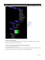
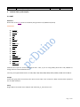
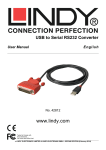
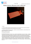
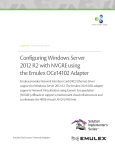
Source tree of Arduino library:
Page 4 of 20
Doc Title
Arduino Programming Guide on pcDuino
Version
0.1
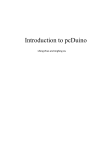
Toolchain of the Arduino library
The source code could be compiled with GCC tool chain. The GCC is pre-installed on the board. You could
enter gcc in Ubuntu terminal under any directory.
Cautious: you may need a bridge board to work with 5V Arduino Shield
All IO on the pcDuino board are 3.3V IO.
If the Arduino shield needs 5V input or 5V output, you need a bridge board for pcDuino. Otherwise, you may
damage your pcDuino board if you directly connect your shield with the pcDuino.
Page 5 of 20
Doc Title
Arduino Programming Guide on pcDuino
Version
0.1
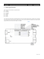
2. Arduino stype I/O interface
Here is the list of I/O interfaces on pcDuino board.
14 GPIOs
One UART
Six PWMs
Six ADCs
One SPI
One I2C
User could connect the Arduino shield with pcDuino via any of the I/O interfaces above. It allows users to leverage
the existing Arduino code and apply to pcDuino easily. There are some limitations and differences compared with
original Arduino board. Please refer chapter 3 for details.
Page 6 of 20
Doc Title
Arduino Programming Guide on pcDuino
Version
0.1
3. Arduino library and samples
3.1 UART
Reference:
Please refer to the Serial class from Arduino (http://arduino.cc/en/Reference/Serial).
F u n c t i o ns
if (Serial)
available()
begin()
end()
find()
findUntil()
flush()
parseFloat()
parseInt()
peek()
print()
println()
read()
readBytes()
readBytesUntil()
setTimeout()
write()
serialEvent()
UART Rx and Tx pins are shared with GPIO 0 and 1. Thus, if you are using UART, please don’t call pinMode to
change function mode of GPIO 0 and 1.
Currently, the supported baud rates are: 300, 600, 1200, 2400, 4800, 9600, 19200, 38400, 57600 and 115200 Hz.
Sample
Accept the typing from the terminal, then print out the input in the second line. Both read and write operations
are via UART interfaces.
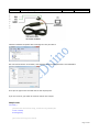
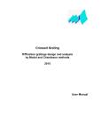
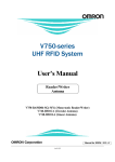
Setup
Plugin USB-to-serial cable to PC USB port and install usb_to_serial driver to PC
Page 7 of 20
Doc Title
Arduino Programming Guide on pcDuino
Version
0.1
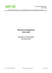
Check the windows computer device manager for com port device.
Run a terminal tool like “sercureCRT”, and configure the serial port parameters to 115200 8N1.
Then you can type on the terminal and see the output prints.
If you use Linux PC, you could use minicom tool for this sample.
Sample code
void setup() {
//Initialize serial with baudrate setting, the default config is SERIAL_8N1
int rate = 115200;
Serial.begin(rate);
//you will see the string on the terminal
Page 8 of 20
Doc Title
Arduino Programming Guide on pcDuino
Version
0.1
Serial.println("Serial begin: ");
}
void loop() {
//if you type the character in the terminal, available() will return the size you typed
if (Serial.available() > 0) {
// read the incoming byte:
char thisByte = Serial.read();
//print it on the terminal with DEC format
Serial.print("I received: ");
Serial.println(thisByte, DEC);
}
delay(200);
}
Page 9 of 20
Doc Title
Arduino Programming Guide on pcDuino
Version
0.1
3.2 ADC
Arduino functions
analogReference()
pcDuino has the internal reference voltage. For ADC0 and ADC1, the reference is 2V, for ADC2~5, the refernece is
3.3V. Thus, this function doesn’t change the reference voltage which is different from original Arduino board.
analogRead()
ADC0 and ADC1 are 6-bit ADC, the return value is from 0 ~ 63, ranging from 0V to 2V.
ADC2~ADC5 are 12-bit ADC, the return value is from 0 ~ 4095, means from 0V to 3.3V.
Notes:
1. If you want to measure the high voltage, you can purchase the bridge board for pcDuino, it can measure max
5V input.
2. For ADC0 and ADC1, though this function will return in 4us, the actual conversion rate is 250Hz. So if the input
voltage changed, it can be detected in 4ms. For ADC2~ADC5, this function will return in 35us, the return value
is the actual value measured.
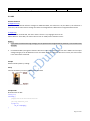
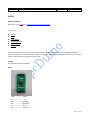
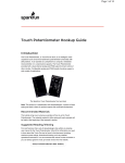
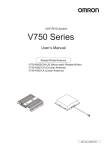
Sample
Measure thedry battery’s voltage
Setup
Connect the battery’s N to any GND and P to the ADC1
Sample Code
Read the value of ADC
Int adc_id = 0;
void setup() {
//argv[1] store the adc id that will be measured.
//if no args, default adc_id is 0
if ( argc == 2 )
adc_id = atoi(argv[1]);
}
Page 10 of 20
Doc Title
Arduino Programming Guide on pcDuino
Version
0.1
void loop() {
// get adc value
int value = analogRead(adc_id);
//delay some time in loop
delayMicroseconds(100000);
}
Page 11 of 20
Doc Title
Arduino Programming Guide on pcDuino
Version
0.1
3.4 PWM
Reference
analogWrite()
- with value 0 to set the PWM IO to low level.
Notes:
1. PWM1 and PWM2 are hardware PWMs. They are set to 520Hz with 256 duty cycle level by default.
PWM1/3/4/5 are 5Hz with 10 duty cycle level by default. Thus, the actual duty level is value*10/256.
PWM1/3/4/5 are simulated by GPIO in software, so they couldn’t set high frequency. If you need simulate high
frequency and accurate PWM with software GPIO, the CPU will be in very high use.
2. The six PWM pins are shared with GPIO, and PWM4/PWM5 pins are also shared with SPI IO. So if you are using
PWM, don’t call pinMode() or SPI function to specific IO.
Functions not implemented
tone()
noTone()
tone function can generate a square wave with the setting frequency and duration.
You can’t use tone function to play the ringtones as Arduino does, because pcDuino’s tone function can work
under just several frequency setting. We will improve this in future release.
An extend function will be provided for those who needs higher or lower frequency PWM. So far, we couldn’t
support 256 duty cycle level in every frequency. Assume the max duty cycle in this frequency is max_level, the
actual level will be level * max_level/256. This function is also useful for tone() function.
PWM1/3/4/5 will be improved in future release. The ultimate goal is to provide 500Hz support with 256 duty
cycle.
Sample
Use PWM to control buzzer to make sound in different frequency
Setup
A buzzer connect to PWM1
Sample code
int pwm_id = 1;
int duty_level = 128;
Page 12 of 20
Doc Title
Arduino Programming Guide on pcDuino
Version
0.1
void setup() {
//set the default freq (#define default_freq 0)
//PWM0/3/4/5, default_freq is 5Hz, and PWM1/2 is 520Hz
if ( argc > 1 )
pwm_id = atoi(argv[1]);
if ( argc > 2 ) //duty level can be 0 ~ 256
duty_level = argv[2];
//start the PWM
analogWrite(pwm_id, duty_level);
}
void loop() {
//delay in loop
delay(10);
}
Page 13 of 20
Doc Title
Arduino Programming Guide on pcDuino
Version
0.1
3.4 GPIO
Reference functions
pinMode()
digitalRead()
digitalWrite()
pulseIn()
Sample
Turn on or off LED by pressing and releasing the button connected to the GPIO
Setup
Connect the shield to the GPIO1 and connect the LED to GPIO5
Sample code
int led_pin = 5;
int btn_pin = 1;
void setup() {
if ( argc == 3 ) {
btn_pin = atoi(argv[1]);
led_pin = atoi(argv[2]);
}
//set the gpio to input or output mode
pinMode(led_pin, OUTPUT);
pinMode(btn_pin, INPUT);
}
void loop() {
//press btn_pin to turn on LED
int value = digitalRead(btn_pin);
if ( value == HIGH )
{ // button pressed
digitalWrite(led_pin, HIGH); // turn on LED
} else { // button released
digitalWrite(led_pin, LOW); // turn off LED
}
Page 14 of 20
Doc Title
Arduino Programming Guide on pcDuino
Version
0.1
delay(100);
}
Page 15 of 20
Doc Title
Arduino Programming Guide on pcDuino
Version
0.1
3.5 I2C
Reference function
Please refer to the Wire class (http://arduino.cc/en/Reference/Wire)
F u n c t i o ns
begin()
requestFrom()
beginTransmission()
endTransmission()
write()
available()
read()
onReceive()
onRequest()
pcDuino I2C is set 200KHz, 7-bit version, master only by default
Future improvements:
Function will be provided to users to allow them to configure the I2C frequency. And we will also support 10-bit
mode.
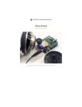
Sample
Read the X, Y and Z coordinates for triple axis via I2C interface
Setup
Connect the I2C port of Triple-Axis with pcDuino
Sample code
Page 16 of 20
Doc Title
Arduino Programming Guide on pcDuino
Version
0.1
Please refer to adxl345_test.c
Page 17 of 20
Doc Title
Arduino Programming Guide on pcDuino
Version
0.1
3.6 SPI
Reference functions
Please refer to the SPI class. (http://arduino.cc/en/Reference/SPI)
F u n c t i o ns
begin()
end()
setBitOrder()
setClockDivider()
setDataMode()
transfer()
pcDuino SPI only works in master mode. The max speed is 12MHz. Clock divider can be 2/4/8/16/32/64/128.
Note that calling the setClockDivider() function just saves the setting of clock divider but without the real clock
change. It works when the transfer function called.
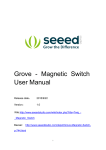
Sample
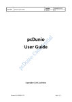
To read an SPI flash ID of M25P16
Setup
GND ---------- GND
V3.3 ---------- 3.3V
DO ---------- SPI_MISO
DI ---------- SPI_MOSI
CS ---------- SPI_CS
CLK --------- SPI_CLK
Page 18 of 20
Doc Title
Arduino Programming Guide on pcDuino
Version
0.1
Sample code
int ReadSpiflashID(void) {
char CMD_RDID = 0x9f;
char id[3];
int flashid = 0;
memset(id, 0x0, sizeof(id));
id[0] = SPI.transfer(CMD_RDID, SPI_CONTINUE);
id[1] = SPI.transfer(0x00, SPI_CONTINUE);
id[2] = SPI.transfer(0x00, SPI_LAST);
//MSB first
flashid = id[0] << 8;
flashid |= id[1];
flashid = flashid << 8;
flashid |= id[2];
return flashid;
}
void setup() {
// initialize SPI:
SPI.begin();
}
void loop() {
//MSB first
printf("spi flash id = 0x%x\n", ReadSpiflashID());
delay(2000);
}
Page 19 of 20
Doc Title
Arduino Programming Guide on pcDuino
Version
0.1
Page 20 of 20