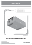
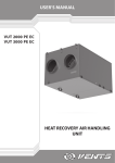
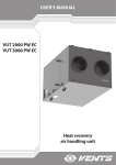
1
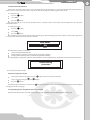
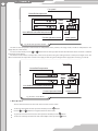
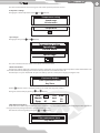
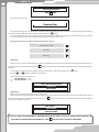
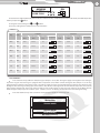
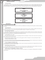
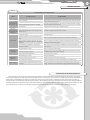
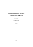
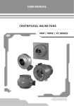
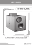
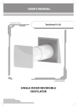
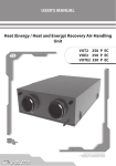
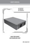
USER`S MANUAL
VUT 350 EH VUT 500 EH
VUT 530 EH
VUT 600 EH
VUT 800 EH
VUT 1000 EH
VUT 1500 EH
VUT 2000 EH
Heat recovery air handling unit
2
CONTENT
Introduction
Use
Delivery set
Structural designation key
Technical data
Safety requirements
Structure and operating logic
Mounting and set-up
Condensate drain
Connection to power mains
Unit control
Maintenance
Fault handling
Storage and transportation rules
Manufacturer’s warranty
Acceptance certificate
Electrical connection certificate
Acceptance certificate
Seller’s information
Mounting certificate
Warranty card
3
3
3
3
3
6
7
9
10
11
14
20
21
22
22
23
23
23
23
23
24
VUT EH
3
INTRODUCTION
The present user manual consisting of technical details, operating instructions and technical specification covers the installation of
the VUT...EH air handling unit with heat recovery, VENTS series, hereinafter referred as the unit.
USE
The unit with a heat exchanger and an electric heater is a heat recovery device and is one of the energy saving components used in
buildings and premises. The unit is a component unit and is not designed for independent operation.
The unit enables continuous air exchange by means of mechanical ventilation in private residences, offices, hotels, cafes, conference
rooms, etc. as well as recovery of the waste heat energy contained in the extract air to warm up the clean supply air.
Transported air must not contain any flammable or explosive mixtures, evaporation of chemicals, coarse dust, soot and oil particles,
sticky substances, fibrous materials, pathogens or any other harmful substances.
The unit is not intended to be used by children, physically or mentally disabled persons, persons with
sensory disorder, persons with no appropriate qualification.
Any operations with the unit must be performed only by properly qualified personnel after the
appropriate safety briefing.
The unit installation sites must prevent access by unattended children.
DELIVERY SET
Unit - 1 item;
Wall-mounted control panel - 1 item;
User’s manual - 1 item;
Packing box - 1 item.
DESIGNATION KEY
VUT ХХХ EH
Spigot orientation:
H - horizontal
Heater type
E - electric
Air capacity [m3/h]
350, 500, 530, 600, 800,1000,1500, 2000
Unit type
VUT - heat recovery ventilation
TECHNICAL DATA
The unit is designed for indoor application with the ambient temperature ranging from +1 °C up to +40 °C and relative humidity up
to 80%.
The unit is classified as a class I electric appliance.
Hazardous parts access and water ingress protection standard:
Unit motors - IP 44;
Unit assembly connected to air ducts - IP 22.
For the main overall and connecting dimensions, outer view and technical data, refer to Fig. 1, 2 and in Tables 1, 2 and 3.
The unit design is regularly improved, so some models may slightly differ from those ones described in this manual.
B
4
F
I
K
Ø
D
A
H
C
G
E
Fig. 1. VUT 350…600 EH overall and connecting dimensions
Table
Табл. 1
Type
Dimensions [mm]
A
B
C
D
E
F
G
H
I
K
VUT 350 EH
996
403
954
124
1057
554
497
100
119
111
VUT 500 EH
996
403
954
149
1057
554
497
100
119
111
VUT 530 EH
996
403
954
159
1057
554
497
100
119
111
VUT 600 EH
996
403
954
199
1057
554
497
100
119
111
VUT EH
5
M
K
G
F
L
ØD
C
A
E
I
B
H
Fig. 1. VUT 800…2000 EH overall and connecting dimensions
Table 2
Type
Dimensions [mm]
I
K
L
M
VUT 800 EH
1117 460
A
B
1071
C
249 1176
D
E
832
F
698 613
G
H
80
126
154
386
VUT 1000 EH
1117 460
1071
249 1176
832
698 613
80
126
154
386
VUT 1500 EH
1394 581
1345
314 1447
947
814 842
200
394
201
320
VUT 2000 EH
1394 581
1345
314 1447
947
814 842
200
394
201
320
6
Table 3
VUT 350
EH
VUT
500 EH
Max. fan power [W]
2 items х
130
2 items
х 150
Max. fan current [A]
2 items х
0,60
Electric heater power [kW]
3,0
Type
VUT 600
EH
VUT 800
EH
VUT
1000 EH
2 items
х 150
2 items х
195
2 items
х 245
2 items х
410
2 items х
490
2 items
х 650
2 items
х 0,66
2 items
х 0,66
2 items х
0,86
2 items
х 1,08
2 items х
1,8
2 items х
2,15
2 items
х 2,84
3,0
4,0
4,0
9,0
9,0
18,0
18,0
Supply voltage, 50 Hz [V]
VUT 530
EH
1~230
VUT
1500 EH
VUT
2000 EH
3~400
Electric heater current [A]
13
13
17,4
17,4
13
13
26
26
Total unit power [kW]
3,26
3,3
4,3
4,39
9,49
9,8
18,98
19,30
Total unit current [A]
14,2
14,32
18,72
19,1
15,16
16,6
30,3
31,7
Max. air capacity, m /h
350
500
530
600
800
1200
1750
2200
3
Rotation speed [min ]
1150
1100
1100
1350
1650
1850
1100
1150
Noise level, 3 m [dB(A)]
24-45
28-47
28-47
32-48
48
60
49
65
Transported air temperature [°C]
-25 up to
+55
-25 up
to +50
-25 up
to +50
-25 up
to +55
-25 up
to +45
-25 up to
+40
-25 up to
+45
-25 up
to +40
-1
Casing material
aluzinc
Insulation
25 mm mineral wool
50 mm mineral wool
extract
Filter:
G4
supply
Connected air duct diameter [mm]
F7
G4 (F7)*
Ø 125
Ø 150
Ø 160
Weight [kg]
45
49
49
Heat recovery efficiency [%]
up to 78
up to 88
Ø 200
Ø 250
Ø 315
54
85
96
up to 85
up to 78
up to 77
Heat exchanger type
cross flow
Heat exchanger material
aluminium
*option
SAFETY REQUIREMENTS
While operating and mounting the unit consider the requirements of the present operation manual as well as general requirements
of all applicable local and national building and electrical codes and standards.
The unit must be grounded!
Before connecting the unit to power mains make sure that the unit is free of any visible damages or any other foreign objects inside
the casing that can damage the impeller blades.
Mounting and connection of the unit to power mains only by duly qualified electricians with valid electric work permit!
The unit is not rated for operation in an environment that contains toxic or aggressive substances as acids, alkalis, organic solvents,
soot, paint as well as sputtered particles of explosive or aggressive substances. The unit is not rated for use in areas where atmospheric
conditions are determined by sea climate or hot springs.
Disconnect the unit from power supply prior to mounting, maintenance,
connection and repair works!
Do not!
• Do not operate the unit beyond the specified temperature range or in an
aggressive and explosive medium!
• Do not connect clothes dryers or similar equipment to the ventilation system!
• Do not operate the unit in the air and dust mixture medium!
VUT EH
7
DESIGN AND OPERATING LOGIC
The unit has the following operating logic, Fig.3:
Warm stale extract air from the room flows through the air ducts to the unit, where it is filtered, then air flows through the heat
exchanger and is exhausted outside by the extract fan through the air ducts. Clean cold air from outside is moved by the supply fan to
the unit, where from it is directed to the supply filter. Then filtered air flows through the heat exchanger and moves to the room through
the air ducts.
Heat energy of warm extract air is transferred to clean intake fresh air from outside and warms it up. Heat recovery minimizes thermal
energy losses, energy demand and operating costs for supply air heating accordingly.
The unit is a framework construction that includes six rigidly fixed 25 mm (for the VUT 350...600 EH units) and 50 mm (for the VUT
800...2000 EH units) thick sandwich panels. The three-layer sandwich panels are made of two galvanized steel sheets, internally filled with
thermal- and sound-insulated layer of mineral wool.
The air supply and exhaust units are equipped with quick-release access panels with special gaskets for easy repair and maintenance.
The terminal box (see Fig. 4: item 13 for VUT 350..600 EH) or the control unit (see Fig. 4: item 10 for VUT 800..2000 EH) contains the terminal
block. The power and ground cables are routed to the terminal block through sealed lead-ins.
Extract air
Supply air
Fig. 3. Operating logic
Intake air
Exhaust air
8
3
4
12
VUT 350…600 EH
5
1. Supply fan
2. Extract filter
3. Heat exchanger
4. Supply filter
5. Extract filter
6. Drain pipe
7. Electric heater
8. Bypass
9. Wall-mounted control panel
10. Control unit
11. Drain pan
12. Quick-detachable panels
13. Terminal box
9
2
6
11
7
8
10
5
1
10
13
VUT 800…2000 EH
9
4
8
7
1
3
2
11
6
12
Fig. 4. Unit design
The basic unit configuration includes:
a wall-mounted control panel with a cable connection to the control system;
supply and exhaust fans with forward-curved impeller blades, maintenance-free electric motors with external rotors and builtin thermal protection;
cross-flow plate heat exchanger;
electric heater with overheating protection: two thermal switches, one of which is a safety switch (+60 °C) with automatic reset
on temperature dropping back to normal and the other is an emergency switch (+90 °C) with manual reset on pressing the
«RESET» button;
supply air filter (filter class (F7));
extract air filter (filter class G4).
VUT EH
9
MOUNTING AND SET-UP
The unit is suspended to the mounting surface through the threaded rod fixed inside the threaded dowel. The unit is also suitable also
for mounting to a horizontal mounting surface, Fig. 5.
While mounting the unit provide the minimum required access to the unit for maintenance and repair. The required minimum
distances from the unit to the wall is shown in Fig. 6.
Suspended mounting
Example
nut
washer
vibration-absorbing
rubber
nut and lock-nut
Mounting to horizontal
surface
Fig. 5. Unit mounting
500
A
A = 600 mm (VUT 350-1000 EH)
А = 850 mm (VUT 1500-2000 EH)
Fig. 6. Minimum unit mounting distances
10
Precautions:
The unit is designed for mounting on a rigid and stable structure in compliance to the technical data and unit weight.
The unit is mounted with anchor bolts. Make sure that a mounting construction has sufficient load capacity for the unit weight.
Otherwise reinforce an installation place by beams, etc. Then insert threaded rods inside the threaded dowels in the ceiling. If the
construction rigidity is not sufficient enough it can resonate with the unit and generate abnormal noise and vibration.
While mounting the unit provide enough service space and an access door for maintenance of the filters, heat exchanger and fans.
One access door is required for each unit. For details, refer to the outline drawing, fig. 1.
Install anchor bolts M8 into the fixation for the ceiling suspension mount and fix it with nuts and washers.
Make sure the unit casing has no foreign objects inside, like paper and foil.
If the threaded bolts used for the unit mounting are too short the unit can generate abnormal noise and resonate with the ceiling.
If the unit connection place to the spiral seam duct is supposed to be the source of the abnormal noise, replace the spiral air duct with
a flexible air duct. The precautions referred above are normally sufficient to solve the resonance problem.
The flexible connectors may be also installed to troubleshoot the resonating problem.
To attain the best performance of the unit while mounting provide a straight 1 m duct section on both sides of the unit.
Access to the unit must be prevented by installing a protecting grille or any other device with the mesh width up to 12.5 mm.
CONDENSATE DRAINAGE
min 3 °
The unit must be connected to sewage collection system, fig. 7. Connect the pipe, U-trap (not included in delivery package) and
sewage collection system with metal, plastic or rubber connecting pipes, fig. 7. The pipe slope downwards must be at least 3°. Fill up
the system with water before connecting the unit to the power mains! The U-trap must be filled with water at all times during the unit
operation. Make sure that the water flows freely into the sewage collection system or otherwise condensed water may build up in the
unit during heat recovery.
The condensate drainage system is designed for normal operation in premises with air temperatures above 0 °C. If the expected air
temperatures are below 0 °C the condensate drainage system must be equipped with heat insulation and pre-heating facilities.
min 3°
drain pipe
tube
U-trap
tube
sewage system
Fig. 7. Condensate drainage
Do not connect several drain pipes from several air handling units to one U-trap!
Direct condensate outside without connection to drain system is not allowed!
VUT EH
11
POWER MAINS CONNECTION
CONNECTION TO POWER MAINS SHALL ONLY BE PERFORMED BY QUALIFIED PERSONNEL AFTER CAREFUL
READING OF THE USER’S MANUAL.
THE UNIT IS INTENDED FOR AC MAINS SUPPLYING THE VOLTAGE COMPLIANT WITH THE TECHNICAL DATA TABLE.
CHECK THE CABLE FOR CHOKING. DO NOT TURN ON THE UNIT IF THE CABLE IS DAMAGED. NEVER UNPLUG THE
UNIT FROM THE SOCKET WITH WET HAND OR BY HOLDING THE ELECTRIC CABLE.
THE RATED ELECTRICAL PARAMETERS OF THE UNIT ARE GIVEN ON THE MANUFACTURER’S LABEL. ANY
TAMPERING WITH THE INTERNAL CONNECTIONS IS PROHIBITED AND WILL VOID THE WARRANTY.
VUT 350..600 EH units must be connected to single-phase 230 / 50 Hz AC mains. VUT 800..2000 EH units must be connected to threephase 400 V / 50 Hz AC mains depending on the unit type (see Table 3 and Fig. 8). The connection must be made using durable, insulated
and heat-resistant conductors (cables and wires) of appropriate section (see Table 4).
The above conductor cross sections are for reference only. The conductor section selection shall account for the wire type, maximum
permissible wire heating, insulation, length and installation method.
Use only copper core wires. The unit must be properly grounded.
The unit shall be connected to power mains on the terminal block mounted inside the terminal block (VUT 350..600 EH) or inside
the control unit (VUT 800..2000 EH) in accordance with the external connections diagram and terminal designations. All the control and
power wires must be connected according to the terminal markings and the electric polarity!
The unit must be connected to the power mains via an automatic circuit breaker with a magnetic breaker integrated into the house
cabling . The trip current shall be at least equal to the rated current consumption of the unit (see Table 3 and 4).
Single-phase mains
(VUT 350… 600 EH)
L
~230 V
50 Hz
N
PE
QF
X1
L
1
N
2
РЕ
3
Three-phase mains
(VUT 800… 2000 EH)
~400 V
50 Hz
X1
QF
L1
L1
1
L2
2
L3
3
N
4
РЕ
5
L2
L3
N
PE
Unit
Unit
Fig. 8. Unit wiring diagrams
Table 4
Type
Automatic circuit
breaker rated current
Copper-core
cable
VUT 350..600 EH
20 A, single-phase
3 х 2,5 mm2
VUT 800..1000 EH
20 A, three-phase
5 х 2,5 mm2
VUT 1500..2000 EH
40 A, three-phase
5 х 4 mm2
12
External devices.
The control panel has a built-in temperature sensor. Therefore, while installing the panel in the operating area ensure at least 1 m
clearance from heating equipment, doors and windows.
The panel is attached to the wall using the self-tapping screws supplied.
The data cable connecting the control panel and the unit shall be routed separately from the power cables. The recommended
minimum distance between the cables is 150 mm.
The control panel is supplied pre-assembled and connected to the unit by the manufacturer. If the repeat installation is necessary,
follow the following steps:
Dismantle the control panel (see Fig. 9):
a) Open the control panel box by pressing on the ends;
b) Use a screwdriver to disconnect the cable from the terminal block;
c) Disconnect the data cable.
a)
b)
Fig. 9. Control panel disconnection
Attach the cable as necessary.
Assemble the control panel:
a) Route the cable through the access hole in the bottom lid;
b) Fix the control panel bottom lid where desired and ensure a secure fit of the lid to the wall by tightening the self-tapping screw. The
screw head must be clear of the control panel circuit board otherwise causing a risk of equipment damage!
c) Strip the cable of the protective insulation (~20 mm);
d) Strip the wires (~6 mm);
e) Attach the wires to the terminal block according to the markings on the label and the wire colouring:
yellow+
greenВ
brownА
white ┴
f ) Snap the control panel casing in place.
Run the cable through the sealed lead in the control unit casing and connect it to the terminal block contacts (Fig. 10).
VUT EH
13
а)
b)
e)
f)
yellow
green
brown
white
+
В
А
Fig. 10. Control panel connection
The temperature sensors are pre-attached by the manufacturer.
For sensor connections on the controller circuit board see Fig. 11.
CONTROLLER CIRCUIT BOARD
WALL-MOUNTED CONTROL PANEL
Terminal block on
the panel
yellow
+
green
В
brown
А
white
Data cable
1
2
3
4
Outdoor air t°
sensor connector
Fig. 11. Connection to controller circuit board
Supply air t°
sensor connector
Controller circuit
board terminal block
yellow
1
green
2
brown
3
white
4
14
UNIT CONTROL
1. General description of the automatic control system.
The unit is controlled via the remote-mounted control panel (Fig. 12). The physical «control panel-unit» data transfer channel is
performed via a four-core data cable up to 10 m in length.
The system enables supply and exhaust fan air capacity control in 3 speed increments:
1 - the minimum speed used in non-residential premises over weekends and holidays or in residential premises at night time;
2 - normal ventilation speed;
3 - intensive ventilation mode when extra air supply is required.
The temperature sensors enable optimum operation mode selection by the system in order to maintain pre-set temperature in
the air duct.
The control panel is equipped with a temperature sensor thereby enabling maintaining of the set (user-defined) indoor
temperature at the selected fan speed or in accordance with the set service function mode (see below). The necessary operation mode
selection as well as the current parameters (i.e. indoor temperature, set temperature, fan speed and heater power) are indicated on the
LCD display.
The energy-saving optimization program calculates the heater power required to sustain the temperature on the premises with
up to 1°C accuracy while adjusting the heater power to 1%.
The air damper (bypass damper) protects the heat exchanger against freezing at low supply air temperature and, if necessary,
excludes supply air from the heat exchange (heat exchanger bypass mode) in the cold ventilation mode.
The system state monitoring program controls the operating parameters of the unit and initiates emergency shutdown in
dangerous situations (i.e. heater overheating or communication loss) by sending corresponding signals to the control panel. Filter
replacement warnings are displayed at user-defined intervals (see below).
All the settings made by the user are saved in the non-volatile memory of the control panel.
2. Remote control panel.
2
3
9
1
4
5
6
7
8
1. Control panel display.
2. The right LED indicates an emergency or malfunction (steady glow) or filter replacement necessity (blinking).
3. Temperature sensor.
4. «Up» button - menu navigation (cursor up) or increasing the current parameter value.
5. «Down» button - menu navigation (cursor down) or decreasing the current parameter value.
«Enter» button - selecting the parameter for modification or jumping one menu level down (entering the menu from the
main operation window).
7. «Escape» button - reverting to the higher menu level (interface language change dialogue in the main operation window).
8. «Power» button - unit state control (on/off ).
9. The green LED indicates the unit status (steady glow - activated, blinking - TEH blowing, off - deactivated).
Fig. 12. Remote control panel
VUT EH
15
3. Unit Activation/Deactivation.
Connect the unit to the power mains 1~230 V/50 Hz (for VUT 350..600 EH units) or 3~400 V/50 Hz (for VUT 800..2000 EH units). For
details, refer to connection to power mains, Page 11. The indicator displays the “VENTS” logo, the LEDs are off.
To activate the unit:
Press the
Select «On»;
Press the
button;
button.
This green LED will go on, the current operation mode is activated and the control panel indicator displays the main operation
window information.
To deactivate the unit:
Press the
Select «Off»;
button;
Press the
button.
The unit switches to the heating elements blowing mode (green LED is blinking) and goes off in 2 minutes. The operation parameters
are selected and modified via the user menu, see below.
Unit status
ON
OFF
Unit deactivation sequence is as follows:
electric heating elements switch off;
The fan switches to a lower speed and continues operating for 2 minutes;
«Heating element blowing» mode is activated. The green LED is blinking.
This operating logic is required to enable heat removal from the electric heating elements and prevent sensor thermal switch activation.
Heater blowing
(2 minutes)
The unit is turned off in 2 minutes.
4. Interface Language Selection.
To change the interface language press the
Select a language using the
Press the
and
button on the main operation window;
buttons;
button.
If no button is pressed within 10 seconds or the
changing the interface language.
button is pressed the indicator will revert to the main operation window without
5. Programming modes using wall-mounted control panel.
Under normal operation the screen will show the main operation window with the following information (Fig. 13):
16
Fan speed
Controlled temperature
Room
Vent.
Heat.
Set
User-defined controlled temperature
Clock
Current operation mode
Heater power
Fig. 13. RC main operation window
The unit has two temperature control modes: air temperature on the premises, the «large circuit», and the air temperature in the
supply duct, the «small circuit».
or
button from the main operation window. This will invoke «Duct» or «Room» controlled
To select a control mode press the
temperature on the display.
The «Room» mode enables air temperature control on the premises using the readings from the control panel integral sensor. The
«Duct» mode enables air temperature control in the supply air duct using the readings from the supply duct sensor (Fig. 13 and 14).
Fan speed
Controlled Temperature
duct
Vent.
Heat.
set
User-Defined Controlled Temperature
Clock
Current Operation Mode
Heater Power
Fig. 14. Unit in «Duct» Mode
6. Menu Operation.
The user menu has two levels: the «main menu» and the «service menu».
To enter the menu from the main operation window press the
Use the
To go back one level and revert to the main operation window press the
To enter the currently selected menu item and modify its values press the
and
button.
buttons to navigate between the menu items.
button.
button.
VUT EH
17
The main menu enables the user to change the critical unit operation parameters such as:
«Temperature Setting»
Changing the control temperature value (
and
buttons).
Temperature setting
Speed stage
Service menu
Temperature
«Speed stage»
Changing the fan speed (
and
buttons).
Temperature setting
Speed stage
Service menu
Speed stage
The service menu lets the user enable and set up the «service» functions:
«Clock and Calendar»
This function enables setting the current date and time required for correct operation of the «Day Timer» and the «Week Timer». The
non-volatile autonomous (battery) power of the clock keeps the time even while the unit is off.
The battery has 2-3 years of useful life. To replace the battery open the control panel casing by pressing the ends.
Clock and Calendar
Filter replacement timer
Day Timer
Use the
button to select a user-defined entry (year, month, date, day, hour, minute).
Change the selected entry by pressing
and
buttons.
Year
Month
Date
07
01
01
Day
Hour
Min.
MON
12
34
«Filter Replacement Timer»
Enables the user to define the period after which the control panel will switch to the «reminder mode» displaying the filter replacement
message. The factory setting for the filter replacement timer is 99 days.
This interval can be changed by pressing the
and
buttons.
Clock and Calendar
Filter replacement timer
Day Timer
18
Filter replacement
after 78 days
Filter replacement message:
Replace filter
The reminder message pops up periodically for a brief time replacing the main operation window (the red LED will blink). To acknowledge
button.
the reminder enter the «Filter Replacement Timer» menu and press the
The next reminder will appear after the period of time defined by the user. While in the reminder mode the unit will operate normally.
To replace the filters power off the unit first. Replace the filters and then turn the unit on.
The unit can be in any one of the current operation modes such as:
Manual (the user may set the parameters, the day and
weekly timers are off )
P
Day Timer
С
Week Timer
H
«Day timer»
Enables the user to set the time for switching the unit on and off. While in this mode the unit will switch on and off automatically in the predetermined time every 24 hours. Furthermore, the
operation.
С
indicator will show at the «Current Operation Mode» position signalling the Day timer
To change the user-defined position (activation time, deactivation time - hours and minutes) press the
Press the
and
button .
buttons to modify the selected entry.
The factory settings for the Day timer are:
«Turning ON time» - 06:30;
«Turning OFF time» - 23:30.
Filter replacement timer
Day Timer
Week timer
«Week Timer»
Enables the user to program the unit for any day of the week.
While in this mode the unit will automatically (according to the pre-set parameters) change the fan speed and controlled temperature at
the time and on the days as defined by the user. Furthermore, the
the activated weekly timer operation.
H
indicator will show at the «Current Operation Mode» position signalling
Day Timer
Week timer
Season mode
The Day timer has higher priority therefore while the Day timer is active the «Current Operation Mode»
position of the main operation window will show
С
irrespective of the weekly timer mode.
VUT EH
19
ON
MONDAY
23:00-08:00
08:00-23:00
To select the user-defined position (day of the week, timer status on the day - on/off, unit operation time in the mode, controlled temperature,
and fan speed) use the
button.
To change the selected entry press
and
buttons.
The factory settings for the weekly timer are stated in Table 5.
Table 5
Interval 1
Day
State
Mon
Interval 2
Activation
Time
Deactivation
Time
Temperature
[°C]
On
8:00
18:00
23
18:00
8:00
20
Tue
On
8:00
18:00
23
18:00
8:00
20
Wed
On
8:00
18:00
23
18:00
8:00
20
Thu
On
8:00
18:00
23
18:00
8:00
20
Fri
On
8:00
18:00
23
18:00
8:00
20
Sat
On
8:00
18:00
23
18:00
8:00
20
Sun
On
8:00
18:00
23
18:00
8:00
20
Fan Speed
Activation Deactivation Temperature
Time
Time
[°C]
Fan Speed
«Seasonal Mode»
In the «Heat Recovery» («Winder» mode) the bypass damper is closed, thus forcing the supply air through the heat exchanger.
To prevent icing the heat exchanger is equipped with a temperature sensor which controls the bypass duct damper. In case of icing
danger the bypass damper on the supply air side is opened. The supply air is then goes through the bypass whereas the exhaust air goes
through the heat exchanger warming up its frozen surface. After the heat exchanger thaws and the exhaust temperature increases the
bypass damper downstream of the heat exchanger shuts closed and the supply air enters the heat exchanger. In the «Open-Closed»
mode the bypass damper operates as follows: open - 5 minutes, closed - 25 minutes, which disables the heat exchanger freezing.
In the «No Heat Recovery» mode («Summer» mode) the bypass damper is constantly open.
Day Timer
Week timer
Season mode
Season mode
Heat recovery
No heat recovery
20
7. Emergency Alarms.
On triggering of either the sensor thermal switch deenergizing the heating elements or in case of filter clogging (which triggers the
differential pressure sensor) or communication line damage the unit enters the emergency «Electric heating elements blowing» mode with
subsequent shutdown in 2 minutes. The red LED goes on, and the control panel displays the message about the malfunction and its origin.
Fault!!!
Heater overheating
Unit OFF
Fault!!!
Filter clogging
Unit OFF
Fault!!!
No communication
Unit OFF
MAINTENANCE
The unit must undergo technical maintenance 3 to 4 times a year. Maintenance includes general cleaning of the unit and the following
operations:
1. Filter maintenance.
Contaminated filters increase air resistance thus impairing supply air delivery into the premises. The filters should be cleaned as they get
dirty, but at least 3-4 times a year. Vacuum cleaning for the air filters is allowed. For new filters contact your Seller.
2. Heat exchanger maintenance.
Even regular technical maintenance of the filters may not completely prevent dirt accumulation on the heat exchanger casing. Clean the
heat exchanger on a regular basis to ensure high heat recovery efficiency. To clean the heat exchanger remove it from the unit and wash with
warm neutral detergent solution. Re-install the dry heat exchanger into the unit.
3. Fan maintenance (once a year).
Even regular technical maintenance may not completely prevent dirt accumulation in the fans which reduces the fan capacity and
impairs supply air delivery into the premises.
Clean the fans with a soft sloth or a brush. Do not use water, aggressive solvents or sharp objects as they may damage the impeller.
4. Condensate drain check (once a year).
The condensate drain (line) may get clogged by dirt and dust particles contained in the exhaust air. Check the drain line operation by
filling the drain pan under the unit with water, clean the U-trap and the drain line, if necessary.
5. Fresh air supply duct check (twice a year).
The supply duct grille may get clogged with leaves and other objects reducing the unit performance and supply air delivery. Check the
supply duct grill twice a year and clean it as required.
6. Duct system check (every 5 years).
Even regular fulfilling of all the prescribed above maintenance operations may not completely prevent dirt accumulation in the air ducts
which reduces the unit capacity. The air duct maintenance includes their periodic cleaning or replacement.
7. Extract shutters and supply diffuser cleaning (as required).
Remove the diffusers and louvre shutters and wash those with hot soap water. Do not change the mounting position of the diffusers
and the shutters.
VUT EH
21
TROUBLESHOOTING
Table 5
Possible faults and troubleshooting
Fault
The fan does not
start up during
the unit start-up.
Automatic
switch tripping
following the unit
turning on.
Low air flow.
Low supply air
temperature.
High noise,
vibration.
Water leakage.
Possible reasons
Fault handling
No power supply.
Make sure that the unit is properly connected to power mains and make
any corrections, if necessary.
Motor is jammed, the impeller are clogged.
Turn the unit off. Troubleshoot the motor jam and the impeller clogging.
Clean the blades. Restart the unit.
System alarm.
Troubleshoot the system alarm. Restart the unit.
Overcurrent resulted from short circuit in the
electric circuit.
Turn the unit off. Contact the service centre.
Low set fan speed.
Set higher speed.
The filters, the fans or the heat exchanger are
dirty.
Clean or replace the filters, clean the fans and the heat exchanger.
The ventilation system components (air ducts,
diffusers, louvre shutters, grilles) are clogged or
damaged.
Clean or replace the ventilation system components, such as air ducts,
diffusers, louvre shutters, grilles.
The air dampers, air diffusers or the louvre
shutters are closed.
Make sure that the air dampers, the diffusers or the louvre shutters are
fully opened.
The extract filter is soiled.
Clean or replace the extract filter.
The heat exchanger is frozen.
Check the heat exchanger condition. Turn the unit off and restart it after
the freeze danger is no longer imminent.
The electric heater malfunction.
Contact the service centre.
The impeller(s) are soiled.
Clean the impeller(s).
The screw connection is too loose.
Tighten the screw connection against stop.
No anti-vibration dampers.
Install anti-vibration mounts (not included into the delivery set).
The drain pipe is clogged, damaged or wrong
mounted.
Clean the drain line, if necessary. Check the drain line slant, inspect the
U-trap and make sure the drain line is equipped with frost protection.
STORAGE AND TRANSPORTATION RULES
Store the unit in a dry and clean weather-protected premise in the manufacturer’s original packing box. Protect the unit against
environmental exposure and dirt ingress until final unit. The unit storage above one year is not recommended. Keep the duly ambient
temperature and humidity in the storage environment. Connection to power mains is allowed only after the unit is kept indoor at
least for 2 hours at room temperature. Use hoist machinery for handling and storage operations to prevent the unit damage. Fulfil the
handling requirements applicable for the applicable freight type. Transportation with any vehicle type is allowed provided that the unit
is protected against mechanical and weather damage. Avoid any mechanical shocks and strokes during handling operations.
22
MANUFACTURER’S WARRANTY
The manufacturer hereby warrants normal operation of the unit over the period of 24 months from the retail sale date provided the
user’s observance of the transportation, storage, installation and operation regulations.
Should any malfunctions occur during the unit operation through the manufacturer’s fault during the warranty period the user is
entitled to elimination of faults by means of warranty repair performed by the manufacturer.
The warranty repair includes work specific to elimination of faults in the unit operation to ensure its intended use by the user within
the warranty period. The faults are eliminated by means of replacement or repair of the complete unit or the faulty part thereof.
The warranty repair does not include:
•
Routine maintenance;
•
Unit installation / dismantling;
•
Unit setup.
To benefit from warranty repair the user must provide the unit, the user’s manual with stamped sale date and the payment document certifying the purchase.
The unit model must comply with the one stated in the user’s manual.
Contact the unit Seller for warranty service.
The manufacturer’s warranty does not apply to the following cases:
•
User’s failure to provide the unit with the entire delivery package as stated in the user’s manual or with missing component
parts previously dismounted by the user;
•
Mismatch of the unit model and make with the respective details stated on the unit packing and in the user’s manual;
•
User’s failure to ensure timely technical maintenance of the unit;
•
External damage to the casing (excluding external modifications of the unit as required for its installation) and the internal
components of the unit;
•
Alteration of the unit design or engineering changes of the unit;
•
Replacement and use of the unit assemblies, parts and components not approved by the manufacturer;
•
Unit misuse;
•
User’s violation of the unit installation regulations;
•
User’s violation of the unit management regulations;
•
Unit connection to the power pains with a voltage different from the one stated in the user’s manual;
•
Unit breakdown due to voltage surges in the power mains;
•
User’s discretionary repair of the unit;
•
Unit repair performed by any persons without the manufacturer’s authorization;
•
Expiry of the unit warranty period;
•
User’s violation of the established regulations specific to the unit transportation;
•
User’s violation of the unit storage regulations;
•
Wrongful acts against the unit committed by third persons;
•
Unit breakdown due to circumstances of insuperable force (fire, flood, earthquake, war, hostilities of any kind, or blockade);
•
Missing seals if provided by the user’s manual;
•
Failure to provide the user’s manual with the sale date stamp;
•
Missing payment document certifying the unit purchase.
FOLLOWING THE REGULATIONS STIPULATED HEREIN WILL ENSURE A LONG AND
TROUBLE-FREE OPERATION OF THE UNIT.
USERS’ CLAIMS SHALL BE SUBJECT TO REVIEW ONLY UPON PRESENTATION OF
THE UNIT, THE PAYMENT DOCUMENT AND THE USER’S MANUAL WITH THE SALE DATE
STAMP.
VUT EH
23
ACCEPTANCE CERTIFICATE
Product Type
Air handling unit with heat recovery
Model
VUT__________EH
Serial Number
Manufacturing Date
is compliant with the technical specifications and is hereby declared ready for service.
Quality Inspector’s
Stamp
SELLER’S INFORMATION
Shop name
Address
Phone number
E-mail
Sales date
This is to certify delivery of the complete unit with the user’s manual. The warranty terms are acknowledged and accepted.
Seller’s seal
Customer’s signature
MOUNTING CERTIFICATE
Air handling unit with heat recovery VUT__________EH has been connected to power mains pursuant
to the requirements stated in the present user’s manual.
Company name
Address
Phone number
Installation technician's
full name
Installation date:
Signature:
This is to certify that the work specific to the unit installation has been performed in accordance with all
the applicable provisions of local and national construction, electrical and technical codes and standards. The unit operates normally as intended by the manufacturer.
Signature:
Installation technician’s
company seal
24
WARRANTY CARD
Product type
Model
Air handling unit with heat recovery
VUT__________EH
Serial number
Manufacturing date
Sales date
Warranty period
Sales company
Seller’s seal
V28EN-03