1
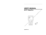
INSTRUCTION MANUAL ST-F35TESTF CCTV Test Meter TABLE OF CONTENTS TABLE OF CONTENTS ............................................................................................................................. 2 SAFETY INFORMATION.......................................................................................................................... 4 PACKAGE CONTENTS .............................................................................................................................. 5 PRODUCT DESCRIPTION........................................................................................................................ 5 FRONT PANEL............................................................................................................................................. 6 SIDE and TOP VIEWS ............................................................................................................................... 8 BATTERY INSTALLATION ..................................................................................................................... 9 OPERATION ...............................................................................................................................................10 POWER ON.............................................................................................................................................10 MENU and FUNCTIONS....................................................................................................................10 PTZ CONTROLLER..............................................................................................................................13 VIDEO SETTING...................................................................................................................................16 CABLE TESTER ....................................................................................................................................17 DATA MONITOR..................................................................................................................................18 DEVICE SETTING ................................................................................................................................18 PTZ ADDRESS SCANNING ...............................................................................................................19 DIGITAL MULTIMETER....................................................................................................................20 DC Voltage Measuring..................................................................................................................20 AC Voltage Measuring..................................................................................................................21 DC Current Measuring .................................................................................................................22 AC Current Measuring .................................................................................................................22 Resistance Measuring ..................................................................................................................23 Continuity Testing.........................................................................................................................24 Diode Testing...................................................................................................................................24 2 DC12V 1A POWER OUTPUT...........................................................................................................25 SPECIFICATIONS......................................................................................................................................26 MULTIMETER SPECIFICATIONS.......................................................................................................27 SUPPORT .....................................................................................................................................................29 3 SAFETY INFORMATION The ST-‐F35TESTF is intended for use in compliance with the local regulations for electrical equipment. The user is not to use the ST-‐F35TESTF in environments or applications for which it is not intended. To prevent damage or failure the ST-‐F35TESTF must not be exposed to water or moisture. The ST-‐F35TESTF is not waterproof and must not be submerged in water or other liquids. Excessive vibration, knocking or dropping of the unit will result in component or product failure. During charging if the battery is found severely hot the ST-‐F35TESTF should immediately be turned off and disconnected from the charger. The ST-‐F35TESTF must not be charged for more than 8 hours. Do not use the ST-‐F35TESTF where the humidity is high. Once the unit is damp, it must be powered off immediately and moved away from any connected cables. Do not use the unit with wet hands. The ST-‐F35TESTF should not be used in any environment where there is flammable gas. Do not use the ST-‐F35TESTF where there is strong electromagnetic interference. Do not disassemble the ST-‐F35TESTF as disassembly may damage the unit and void the warranty. Contact your SecurityTronix dealer for assistance. Only use a slightly damp cloth to clean the unit. Do not use detergents or solvents. 4 PACKAGE CONTENTS This package contains: One ST-‐F35TESTF meter One LAN cable tester One 5V 2A power supply One lithium ion polymer battery One BNC cable One RS485 cable One safety cord One case One instruction manual PRODUCT DESCRIPTION The ST-‐F35TESTF has been developed for the on-‐site installation and maintenance of video monitoring systems. It can be used for displaying video, controlling PTZ, generating images, capturing data via RS485 and testing LAN cables. Its functions, portability and ease of use make it an invaluable test device for the CCTV technician. Key features include: 3.5” TFT LCD display with 960x240 resolution Video Level testing, with video signals measured in IRE or mV DC 12V 1 A power output for camera Audio input testing Digital multimeter – voltage, current, resistance and capacitance can be tested as well as continuity and diode testing PTZ control. Pan/tilts the P/T unit; zooms in/out of the lens; adjusts the focus and aperture; and sets and calls the preset position. Can perform PTZ address scanning with ID search of PTZ cameras. Automatically adapts and displays the video format of NTSC / PAL. Video display LCD brightness, contrast, color saturation are adjustable. NTSC / PAL multi-‐system colorbar video generator (seven system switchable; transmit, receive, seven-‐system color images). Captures and analyzes RS485 control data. Powerful LAN cable testing measuring the connecting status, displaying the sequence of connection and the NO. of the LAN cable. Supports RS232, RS485 and RS422 interfaces with baud rates ranging from 150, 600 to 19200bps. Supports more than twenty PTZ protocols, including PELCO-‐P, PELCO-‐D, SAMSUNG, etc. Advanced power control and protection circuit for its 3.7v DC3000mAh lithium ion polymer battery. Battery can last up to 12 hours for normal use after charging for 4 hours. 5 FRONT PANEL 1 Power Indicator: Lights green while powered on. 2 Data-‐Reception Indicator: Lights red while the data is being received. 3 Data-‐Transmission Indicator: Lights red while the data is being transmitted. 4 Charge Indicator: Lights red while the battery is being charged. When the charging is complete, the indicator turns off automatically. 5 Battery Level: Displays battery life on current charge. 6 Main-‐menu: Displays the ST-‐F35TESTF’s main functions. 6 7 8 9 10 11 12 13 14 15 Sub-‐Menu: Shows and sets the values of functions. Press for more than 2 seconds to turn on/off the tester. Press for less than 2 seconds to turn on/off the PTZ controller menu displaying. Menu Key: Pops up the main-‐menu; constant-‐press MODE or press the key can shift between functions. Setup Key: Press SET or press left or right key to enter sub-‐menu to set the function. Up: Select the item that will be set or add the value of the parameter. Tilt the PTZ upward. Left: Enter the sub-‐menu or select the parameter whose value will be changed. Reduce the value of the parameter. Pan the PTZ left. Right: Enter the sub-‐menu or select the parameter whose value will be changed. Add the value of the parameter. Pan the PTZ right. Down: Select the item that will be set or reduce the value of the parameter. Tilt the PTZ downward. 16 17 18 19 20 21 or Confirm/Open: Confirm the setting of parameters; open the aperture. Return/Close: Return or cancel while setting parameters of the menu; close the aperture Near Focus: Focus the image nearby. Far Focus: Focus the image faraway. TELE: Zoom in the image. WIDE: Zoom out the image. Digital Multimeter 7 SIDE and TOP VIEWS 22 Resets the default parameter settings. 23 External Power Supply (DC, 5V): Use the included power adapter. 24 UTP Cable Port: Use with the UTP LAN cable tester. 25 RS232 Interface: RS232 communication for the PTZ. 26 Audio Input: Test audio on the front end. 27 DC12V1A Power Output: output DC12V power for camera 28 ST-‐F35TESTF Speaker 29 Video Input (BNC input interface): Inputs the video. 30 Video Output (BNC output interface): Outputs the video. 31 RS485/422 Interface: RS485/RS422 communication for the PTZ. 8 BATTERY INSTALLATION The ST-‐F35TESTF has a built-‐in lithium ion polymer rechargeable battery. The battery cable inside battery cabin should be disconnected for safety during transportation! Prior to using the ST-‐F35TESTF, the battery cables inside the battery cabin should be securely connected. Usually it is unnecessary to disconnect the cable during normal use. Pressing key continuously will power the unit on or off. Prior to using the unit for the first time be sure the batteries are completely exhausted and then recharge for 4 or 5 hours. The Charge Indicator lights red when charging the battery and will automatically turn off when charging is completed. When the Charge Indicator turns off, the battery is approximately 90% charged. The charging time can be extended for about 1 hour and the charging time within 8 hours will not damage the battery. The ST-‐F35TESTF can be used while charging. However, the charging time will be extended. Press the RESET key to restore the default settings if the ST-‐F35TESTF works abnormally. 9 OPERATION POWER ON Continuously press the POWER key (at least 2 seconds) to power on / off the ST-‐F35TESTF. When powered on, press the MODE key and the main menu will appear. MENU and FUNCTIONS Press the MODE key continuously or press the or key to select the function (PTZ Controller, Video Settings, Colorbar Generator, LAN Cable Tester, Data Monitors, Device Setting) and enter the corresponding function setting sub-‐menu. Press the SET key to set the parameters in the function sub-‐menu. Note: When the ST-‐F35TESTF is powered on, it will return to the function being operated before it is turned off. 1. PTZ controller Display the input video images. Pan/tilt the P/T unit and zoom in/ out the image. Setup the controlling parameters (e.g., protocol, communication port, baud rate, PTZ ID, pan/tilt speed; set and call preset position). 10 2. Video Setting Adjust the LCD brightness, contrast, color saturation, video format and video level testing. 3. Colorbar Generator Output or receive seven different forms of video colorbar to tester monitor, cable or other equipment. 4. Cable Tester Test LAN cable or telephone cable. The connecting condition and the sequence of wires will be displayed as well as the serial number of the cable tester kit. 11 5. Data Monitor Captures the protocol from the controlling system and displays command data. A helpful tool to debug and maintain RS485 communications. 6. Device setting Set the parameters of the ST-‐F35TESTF (Auto power off/ Keypad tone/Language/Brightness/Address search) 7. Address Search Search the PTZ camera’s ID 8. Digital Multimeter Digital multimeter performs AD/DC voltage, AC/DC current, resistance, continuity, capacitance and diode testing. Supports both Auto and Manual Range, Data Hold and Relative Measuring 12 PTZ CONTROLLER Display the input video images. Has pan/tilt the P/T unit and zoom in/ out the image capability. Setup the controlling parameters (e.g., protocol, communication port, baud rate, PTZ ID, pan/tilt speed; set and call preset position). The following connections should be confirmed before use The Video In interface of the ST-‐F35TESTF and the output interface of camera Data A+ of the ST-‐F35TESTF and A+ of the PTZ camera or controlling device; data B-‐ of the ST-‐F35TESTF and B-‐ of the PTZ camera or controlling device Note: Do not connect the communications interface with a circuit having a voltage greater than 6V. Press the SET key to enter the PTZ controller sub-‐menu. Press the Press the or to select the new value. Press the ENTER key to save the change or press the RETURN key to escape the change. Press the SET key to exit the sub-‐menu. Press the POWER key for a full-‐screen image. or key to select the parameter value to be changed. 13 A. Protocol: Select the protocol according to the PTC camera. Up to 21 popular protocols are available (e.g., Pelco P, Pelco D, Samsung, Yaan, LiLin, CSR600, etc.). B. Port: Select the communications port for the PTZ camera (RS232, RS422, RS485). C. Baud: Select the baud rate for the PTC camera. D. Address: Set the PTZ camera’s ID (0-‐254). E. Pan Speed: Set the PTZ camera’s pan speed (0-‐63). F. Tilt Speed: Set the PTZ camera’s tilt speed (0-‐63) G. Set PS: Set the preset position (0-‐128) a. P/T/Z the camera to desired position. b. Press the SET key to enter PTZ controller sub-‐menu. c. Move the yellow cursor to “Set PS” and then press the preset position number. or key to select d. Press the ENTER key to complete preset position setting or press the RETURN key to escape the preset position setting. H. Go PS: Call the preset position (0-‐128). The PTZ camera will go to the desired preset position. a. Move the yellow cursor to “Go PS” and then press the preset position number. or key to select b. Press the ENTER key to complete preset position calling or press the RETURN key to escape preset position calling. The way of calling the OSD menu and preset of the PTZ camera may vary with control systems from different manufacturers. Read the control system manufacturer’s operation manual for details. By way of example: a. Move the yellow cursor to “PTZ controller” to enter the PTZ controller mode. b. Press the SET key to enter the PTZ controller sub-‐menu. Press key to move the yellow cursor to “Go PS”. or c. Press or key to select the preset number 64, then press the ENTER key to call the OSD menu of the PTZ controller. 14 OSD Menu of Dome (for reference only) MAIN MENU MAIN MENU 1. DISPLAY SETUP 1. Display configuration 2. CAMERA SETUP 2. Set camera parameters. 3. CONTROL SETUP 3. Set PTZ controlling 4. CAMERA MASK SET 4. Set privacy mask 5. PROGRAM 5. Set auto-‐running functions 6. PAL CAMERA 6. PAL/NTSC Switch 7. CAM DEFAULT SET 7. Restore the default settings 8. DOME RESET 8. Reset the dome 9. EXIT 9. Exit the main menu Operate auto-‐running functions by calling preset position (effective for some brands of PTZ camera) Call preset-‐33—Open Auto-‐flip function Call preset-‐34—Reset zero point of PTZ camera Call preset-‐64—Enter the main menu of the PTZ camera Call preset-‐95—Enter the main menu of the PTZ camera or stop the PATTERN recording. Call preset-‐96—Run pattern-‐1 Call preset-‐97—Run preset tour-‐1 Call preset-‐98—Run frame Scan Call preset-‐99—Run Auto scan 15 VIDEO SETTING User can customize the brightness, contrast and saturation of the LCD according to the environment and display the format (PAL/NTSC) of video input. a. Press the or key to select the parameter for which you want to change the value. b. Press the or key to change the value. Press the ENTER key to save the change or press the RETURN key to escape. c. The Video Format and Video Level will be displayed in the lower portion of the screen. If there is no video signal at the Video IN port of the ST-‐F35TESTF, the type of NTSC or PAL , and Video Level will not be displayed. Depending on the type of camera connected to the ST-‐F35TESTF, the Video “Format“ will automatically change between NTSC and PAL, and the Video Level will automatically change between IRE (Institute of Radio Engineers) and mV. NTSC signals measured in IRE units, PAL signals measured in mV. The Video Level should be within the indicated range. Levels that are too low will result in a dim picture with reduced dynamic range. A Video Level that is too high will result in washed out pictures. The ST-‐F35TESTF will display “Normal” when video levels are 1000mV±20%, “Exceed” or “Weak” will be displayed when video level out of 1000mV±20%. COLORBAR GENERATOR (Output Video in any mode) Output or receive seven different forms of video color bar to test monitor, video cable or other equipment. a. Press the or key to select the parameter for which you want to change the value. b. Press the value. or key to change the c. Press ENTER key to save the change or press RETURN key to escape. 16 CABLE TESTER Test LAN cable or telephone cable. Connect LAN cable or telephone cable to the ST-‐F35TESTF and cable tester. The connecting status, cable type and the sequence of wires will be displayed, as well as the serial number of the cable tester kit. The right picture shows lines 1-‐7 are closed, line 8 is open and the number of the cable tester box is 255. Straight-‐through Line Cross Line Open Line or Short 17 DATA MONITOR Data Monitor captures the command data from the RS485 controlling system. a. Connect the RS485 or RS232 interface of the controlling system with the ST-‐ F35TESTF’s RS485 or RS232 ports. In the case of RS485, A to A, B to B. b. Press the SET key and then press or key to select the communications port according to the system connection. Press the SET key to save the change. c. Press or key to select the baud rate according to the controlling system’s baud rate. Press the SET key to save the change and capture the command data from the controlling system. d. Press the RETURN key to clear the screen. DEVICE SETTING Device Setting sets the ST-‐F35TESTF’s parameters. Auto Poweroff: Sets the time for auto shut-‐down (Disable, 5, 10,…60). Disable: Disable the “Auto Poweroff” function. 5 means the unit will power off after 5 minutes of no operation. Keypad Tone: Turn on or off the beep associated with pressing the keypad. Language: Select language of the OSD menu. Brightness: Sets the brightness of the OSD menu and background (0 – 7). Address Search: Off / On. Open or close the PTZ address search menu. a. Press or key to move the parameter you want to change. b. Press or to change the value. c. Press the ENTER key to save the change or press RETURN to escape. 18 PTZ ADDRESS SCANNING Device Setting allows the ID search of the PTZ camera. Note the PTZ camera to be searched must be isolated from other PTZ cameras before beginning the search. Not doing so will cause all PTZ cameras in the same system to pan at the same time. a. Press the MODE key to access the “Device Setting” menu. b. Scroll down to Address Search. Press key to change from “off” to “on”. Press the ENTER key to save the change. Note the ST-‐F35TESTF returns to “off” after shutdown and the scan sub-‐menu closes automatically. Set “on” again for the next use. c. Press the MODE key to enter the sub-‐menu. d. Press the SET key to set the protocol, communications port and communications rate consistent with the PTZ camera. e. Press the NEAR or FAR key to increase or decrease the address values. NEAR: The ST-‐F35TESTF will search up the ID list quickly and continuously (from 1 – 256). When the ID is found the PTZ camera will pan right. At this time press any key to stop the search. FAR: The ST-‐F35TESTF will search down the ID list quickly and continuously (from 256 – 1). When the ID is found the PTZ camera will pan left. Press any key to stop the search. WIDE: The ST-‐F35TESTF will search for the ID step-‐by-‐step (from 1 – 256). When the ID is found the PTZ camera will stop panning. FAR: The ST-‐F35TESTF will search for the ID step-‐by-‐step (from 256 – 1) . When the ID is found the PTZ camera will stop panning. If you press the NEAR key the ST-‐F35TESTF will search up for the ID quickly and continuously (from 1 – 256). When the ID is found the PTZ camera will pan right. Press any key to stop the search. Press TELE key for manual, single-‐step ID search step-‐by-‐step (from 256 – 1). When the ID is found the PTZ camera will stop panning. If you press the FAR key the ST-‐F35TESTF will search down for the ID quickly and continuously (from 256 – 1). When the ID is found the PTZ camera will pan left. Press any key to stop the search. Press the WIDE key for manual, single-‐step ID search step-‐by-‐step from (1 – 256). When the ID is found the PTZ camera will stop panning. Press MODE key to quit the Address Scanning menu. 19 DIGITAL MULTIMETER Function Buttons: Auto Range Data Hold Function Select Relative Measuring Manual Range Symbols: ~ U : AC Voltage Measuring U: DC Voltage Measuring A: DC Current Measuring ~ A: AC Current Measuring Ω: Resistance Measuring : Diode Testing : Continuity Testing : Capacitance Measuring DC Voltage Measuring WARNING: An input of more than 660 VDC may show higher voltage, but doing so may destroy the circuit. Also pay attention not to get an electric shock when measuring high voltage. a. Connect the black test lead to the COM jack and the red test lead to the V jack. b. Press pressing to select U, enter the DC voltage measurement. Auto Range by button, and Manual Range by pressing Manual Ranges: 0.000V 6.6V range 00.00V 66V range 000.0V 660V range 000.0mV 660mV range 20 c. Connect test leads across the source or load under measurement. d. Measurement will be displayed on the screen. The polarity of the red lead connection will be indicated along with the voltage value. NOTE: When only the “OL” figure is displayed the multimeter indicates an over range situation and the higher range has to be selected. When the value scale to be measured is unknown beforehand, set the range selector to the highest position. AC Voltage Measuring WARNING: An input of more than 660 VDC may show higher voltage, but doing so may destroy the circuit. Also pay attention not to get an electric shock when measuring high voltage. a. Connect the black test lead to the COM jack and the red test lead to the V jack. ~ b. Press to select U , enter the AC voltage measurement. Auto Range by pressing button, and Manual Range by pressing Manual Ranges: 0.000V 6.6V range 00.00V 66V range 000.0V 660V range 000.0mV 660mV range c. Connect test leads across the source or load under measurement. d. Measurement will be displayed on the screen. NOTE: When only the “OL” figure is displayed the multimeter indicates an over range situation and the higher range has to be selected. When the value scale to be measured is unknown beforehand, set the range selector to the highest position. 21 DC Current Measuring WARNING: Shut down the power of the tested circuit before connecting the meter to the circuit for measuring. a. Connect the black test lead to the COM jack and the red test lead to the mA jack for a maximum of 660mA current. For a maximum of 10A, move the red lead to the 10A jack. b. Press to select A, enter the DC current measurement. Manual Range by pressing . Manual Ranges: 0.000mA 6.6mA range 00.00mA 66mA range 000.0mA 660mA range 00.00A 10A range (use 10A jack) c. Connect test leads across the source or load under measurement. d. Measurement will be displayed on the screen. NOTE: When only the “OL” figure is displayed the multimeter indicates an over range situation and the higher range has to be selected. When the value scale to be measured is unknown beforehand, set the range selector to the highest position. The maximum current of the mA jack is 660mA. Over-‐current will destroy the fuse and will damage the meter. The maximum current of the 10A jack is 10A. Over-‐current will destroy the meter and may injure the operator. AC Current Measuring WARNING: Shut down the power of the tested circuit before connecting the meter to the circuit for measuring. a. Connect the black test lead to the COM jack and the red test lead to the mA jack for a maximum of 660mA current. For a maximum of 10A, move the red lead to the 10A jack. ~ b. Press to select A , enter the AC current measurement. Manual Range by pressing measuring. . Note that Auto Range will not work for AC current Manual Ranges: 0.000mA 6.6mA range 00.00mA 66mA range 22 000.0mA 660mA range 00.00A 10A range (use 10A jack) c. Connect test leads across the source or load under measurement. d. Measurement will be displayed on the screen. NOTE: When only the “OL” figure is displayed the multimeter indicates an over range situation and the higher range has to be selected. When the value scale to be measured is unknown beforehand, set the range selector to the highest position. The maximum current of the mA jack is 660mA. Over-‐current will destroy the fuse and will damage the meter. The maximum current of the 10A jack is 10A. Over-‐current will destroy the meter and may injure the operator. Resistance Measuring WARNING: When measuring in-‐circuit resistance, be sure the circuit under test has all power removed and that all capacitors have fully discharged. a. Connect the black test lead to the COM jack and the red test lead to the Ω jack. b. Press to select Ω , enter the Ω measurement. Auto Range by pressing the button and Manual Range by pressing the button. Manual Ranges: (connecting the red lead to the black lead will display the measuring range) 000.0Ω 660Ω range 0.000KΩ 6KΩ range 00.00KΩ 66KΩ range 000.0KΩ 660KΩ range 0.000MΩ 6MΩ range 00.00MΩ 66MΩ range c. Connect test leads across the source or load under measurement. d. Measurement will be displayed on the screen. NOTE: When only the “OL” figure is displayed the multimeter indicates an over range situation and the higher range has to be selected. 23 Continuity Testing WARNING: When measuring in-‐circuit resistance, be sure the circuit under test has all power removed and that all capacitors have fully discharged. a. Connect the black test lead to the COM jack and the red test lead to the Ω jack. b. Press to select , and enter the continuity test. c. Connect test leads across to points of the circuit under testing. d. If continuity exists (i.e., resistance less than about 50Ω), the meter’s built-‐in buzzer will sound. e. You can also get a reading from the meter’s screen f. If the input open circuit (or the circuit resistance measured is higher than 660Ω then the “OL” figure will be displayed. Diode Testing a. Connect the black test lead to the COM jack and the red test lead to the b. Press to select Range by pressing the jack. and enter the capacitance measurement test. Auto button and the Manual Range by pressing the button. Manual ranges: 0.000nF 6.6nF range 00.00nF 66nF range 000.0nF 660nF range 0.000µF 6.6µF range 00.00µF 66µF range 000.0µF 660µF range 0.000mF 6.6mF range 00.00mF 66mF range c. Be sure the capacitor has been fully discharged before connecting the test leads across two sides of the capacitor under measurement. d. Measurement readings will be displayed on the meter’s screen. 24 DC12V 1A POWER OUTPUT A camera can be powered with DC12V 1A power from the ST-‐F35TESTF. Do not input any power to the ST-‐F35TEST’s DC12/1A OUTPUT port. Doing so will destroy the unit. Do not output this DC12/1A power to the ST-‐F35TESTF’s power port. Doing so will destroy the unit. If the camera requires more than 1A of current the ST-‐F35TESTF will enter protection mode. If this happens you must disconnect all connections to the ST-‐F35TESTF and then connect the unit to the included power supply to resume. AUDIO INPUT TEST The ST-‐F35TESTF may be used to test audio input from pickup devices. Connect the unit to the pickup device with the included audio cable. 25 SPECIFICATIONS MODEL ST-‐F35TESTF Video Test Signal Mode: NTSC/PAL (Auto adapt) Display: 3.5 inch digital TFT-‐LCD ,960 x 240 resolution LCD Adjustment: Brightness, Contrast, Saturation adjustable Video IN/OUT: 1 channel BNC Input & 1 channel Output Video Output Mode 1.0 Vp-‐p Video Level Test Level Test Video signals measured in IRE or mV PTZ Controller Communication: RS232, RS422 simplex and RS485 PTZ Protocol: Compatible with more than 20 protocols such as PELCO-‐ D/P, Samsung, Panasonic, Lilin, Yaan, etc. Baud Rate: 150,300,600,1200,2400,4800,9600,19200bps Video Signal Generation Colorbar Generation: Output one channel PAL/NTSC colorbar video signal for testing monitor or video cable. Digital Multimeter Multimeter Voltage, current, resistance and capacitance measurement, continuity and diode testing. UTP CABLE TEST UTP Cable Test: Test UTP cable connection status and display in the screen. Read the number of the test box. DC12V 1A Power Output DC12V Power Output: Output DC12V1A power for camera Audio Input Test Audio Input Test: Test the pickup and other audio equipments on the front-‐ end RS485 Data Analyst 26 Captures and analyzes the command data from controlling device Data Monitor: POWER Power Adapter: DC5V, 2A Battery: Built-‐in 3.7V Lithium polymer battery, 3000mAh Rechargeable: After charging 3-‐4 hour, working time lasts 12 hours Low Consumption: Energy saving technology General Working Temperature: -‐22°F to +158°F Working Humidity: 30%-‐90% Dimension/Weight: 7”x 3.7” x 1.4”/ 0.75lb. MULTIMETER SPECIFICATIONS Counts: -‐6600 ~ + 6600 Conversion Rate: 3 ties/s Current modes for clamp meter with ZERO function DC Voltage Range Accuracy 660mV (Manual range) 6.6V 0.1mV ± (0.3% to +4) 66V Resolution 660V 1mV 10mV 100mV AC Voltage Range 660mV (Manual range) Accuracy ±(1.5%+6) 6.6V 66V 660V Resolution 0.1mV 1mV ±(0.8%+6) 10mV 100mV 27 DC Current Range Accuracy 6.6mA Resolution 1uA ±(0.5%+3) 66mA 660mA 10uA 100uA 10A ±(1%+5) 10mA AC Current Range Accuracy 6.6mA Resolution 1uA ±(0.5%+3) 66mA 660mA 10uA 100uA 10A ±(1%+5) 10mA Resistance Range 660Ω Accuracy ±(0.8%+5) 6.6KΩ 66KΩ 660KΩ 0.1Ω 1Ω ±(0.8%+2) 6.6MΩ 66MΩ Resolution 10Ω 100Ω 1KΩ ±(1.2%+5) 10KΩ Continuity Range Function Built-‐in buzzer will sound, if resistance is lower than 50 Ω 28 Diode Range Resolution 1mV Function Display: read approximate forward voltage of diode. Capacitance Range 6.6nF Accuracy ±(0.5%+20) 66nF 660nF 6.6μF Resolution 1pF 10pF ±(3.5%+8) 100pF 1nF 66μF 10nF 660μF 100nF 6.6mF ±(5%+8) 66mF 1μF 10μF SUPPORT For technical support or assistance contact your SecurityTronix sales engineer at 1-‐800-‐ 688-‐9282 29