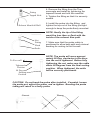
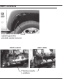
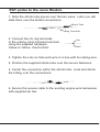
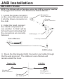
1
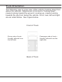
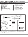
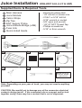
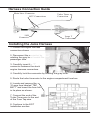
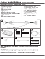
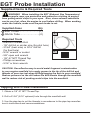
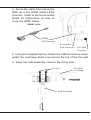
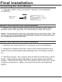
Getting Started
About the Juice
Congratulations on purchasing the Edge Juice/Attitude system for
the Duramax Diesel®.
The Juice/Attitude system features an intelligent module (Juice)
that acts as an add-on Engine Control Module (ECM) for the
Duramax® Engine. This module is controlled and customized in
the cab of your truck by the Attitude monitor/controller.
This system offers many cutting-edge, additional features not
available with the factory setup. Since the Juice Module is an
add-on ECM, it uses data from your truck’s computer or engine
control module (ECM), and then enhances the factory settings to
optimize your truck’s performance. This product offers a wide variety of amazing performance and safety features that can ensure
you get the driving experience you desire without damaging your
valuable truck.
Please take the time to thoroughly review all of the features and
product options outlined in this manual. Taking the time to understand how this product works and how to properly operate this
product will ensure that you have an extraordinary and safe driving experience. If we can be of any assistance to help you get
the most from your product please call us at 888-360-3343. We
are open Monday through Friday from 6am to 6pm MST.
IMPORTANT: Read through these instructions completely
so that you understand each step prior to installation. Refer
to the on dash display User Manual for Safety and Warranty
information.
Safety Terms
Throughout this User Guide (hereafter noted as User Manual or
Manual) you will see important messages regarding your safety
or the protection of your vehicle. These messages are designated by the words WARNING or CAUTION.
WARNING indicates a condition that may cause serious
injury or death to you, your passengers or others nearby. Pay
careful attention to these Warning messages, and always comply
with them. They could save a life.
CAUTION indicates a condition that could cause damage to your
vehicle. It is important to install and operate your EDGE product
in conformance with instructions in this Manual. Caution alerts
you to particularly important things that will keep your vehicle
operating properly.
BENEFITS OF PRODUCT REGISTRATION
-Your Safety - Registering your product allows us to know exactly
which product you have and provide important product updates to
you that improve the quality and/or safety of the product.
-Enhanced Features - Almost all Edge products are easily updated
via the internet. We are constantly adding new features and improvements to our product that we know you will want to enjoy.
-Confirmation of Ownership - Provides a record in case of product
loss, theft, or required warranty work. When you call us for support
our team will already have much of the information they need to help
you.
-Improved Product Development - Helps us better understand you
(our customer) and design products that meet your needs.
-Special Offers - Allows us to inform you about special offers on accessories and/or new products that fit your vehicle and enhance your
driving experience.
Important Notes
1. If you have used another tuner/programmer on your truck,
you will need to program your truck back to stock before using
the Attitude or Juice.
Failure to return to stock may result in PCM failure or
engine damage.
2. Do not program your vehicle in remote location in case of
vehicle failure.
3. All Edge modules and programmers are built to operate with
OEM calibrations. When you take your vehicle to a service
center they may, by your request or otherwise, update your vehicle’s calibrations. It is important that you return your vehicle
to stock before taking it in for service. Edge updates its products to work effectively with updated OEM calibrations. However, Edge is not always made aware of calibration changes
made by the OEM. In the case of discontinued products, Edge
cannot ensure that your unit will work effectively if you take
your vehicle to a dealership and you are given, by your request
or otherwise, a new calibration.
NOTE: This product will not work on E-Series Vans, as
some of the connectors are different from the F-Series
pickups for which this product was designed for.
Truck Orientation
The following view is a top view of the vehicle (looking down from
above the vehicle). References in the text to “looking down”,
means looking toward the ground. Looking up, means looking
towards the sky from below the vehicle. Front, rear, left and right
are as noted below. See Figure below.
Front of Truck
Driver side of truck–
Usually referred to as
the left side.
Passenger side of truck –
Usually referred to as the
right side.
Back of Truck
Juice Installation
2001-2005 6.6L (LB7 & LLY)
Supplied Items & Required Tools
1
2
3
4
5
6
7
Main Harness
Juice Module
Velcro Strips
Zip Ties
EGT Sensor Probe
Juice Attitude Bridge (JAB)
Quick Install Guide
- Electric/Cordless Drill
- 1/8” drill bit or similar size
- 21/64” or 5/16” drill bit
- 9/16” wrench or socket
- 5/8” open end wrench
- 1/8”-27 NPT Thread Tap
- Phillips screwdriver
- 5/16” or 8mm wrench
1
2
3
4
5
6
7
REFER TO QUICK
INSTALL GUIDE
FOR INSTALL
Note: Depending on your year of truck, you may not need
everything provided.
Harness Connection Guide
Main Juice Connector
EGT Connections
Small T
Connectors
JAB
Connector
Large T
Connectors
Installing the Juice Harness
1. Locate the engine harness
connectors shown.
2. Disconnect both connectors by
rotating the gray lever toward the
passenger side.
3. Carefully insert each “T”
connector between the stock
engine harness connectors.
4. Carefully lock the connectors
by rotating the gray levers.
5. Continue to the EGT Installation section.
CAUTION: Be carefull not to damage any of the connector electrical
contacts during install. If the connectors do no connect and/or lock
together easily, there may be a contact that is out of alignment.
Juice Installation
2006-2007 6.6L (LLY & LBZ)
Supplied Items & Required Tools
1
2
3
4
5
6
7
8
- Electric/Cordless Drill
- 1/8” drill bit or similar size
- 21/64” or 5/16” drill bit
- 9/16” wrench or socket
- 5/8” open end wrench
- 1/8”-27 NPT Thread Tap
- Phillips screwdriver
- 5/16” or 8mm wrench
Main Harness
Juice Module
Velcro Strips
Zip Ties
EGT Sensor Probe
Juice Attitude Bridge (JAB)
Fuse Link
Quick Install Guide
1
2
3
6
7
4
5
8
REFER TO QUICK
INSTALL GUIDE
FOR INSTALL
Note: Depending on your year of truck, you may not need everything
provided.
CAUTION: Be carefull not to damage any of the connector electrical
contacts during install. If the connectors do no connect and/or lock
together easily, there may be a contact that is out of alignment.
Harness Connection Guide
Main Juice Connector
EGT Connections
JAB
Connector
Turbo Timer
Connection
Large T
Connectors
Installing the Juice Harness
1. Locate the engine harness
connectors shown.
2. Disconnect the connector by
rotating the gray lever toward the
passenger side.
3. Carefully insert the “T”
connector between the stock
engine harness connectors.
4. Carefully lock the connector by rotating the gray lever.
5. Route the turbo timer wire to the engine compartment fuse box.
6. Locate and remove the
10 amp fuse labeled “TBC
BATT” and insert the fuse link
in its place as shown.
7. Connect the end of the
Turbo Timer wire to the end
of the Fuse Tap wire.
8. Continue to the EGT
Installation section.
Juice Installation
2007.5-2010 (LMM)
Supplied Items & Required Tools
1
2
3
4
5
6
7
8
- Electric/Cordless Drill
- 1/8” drill bit or similar size
- 21/64” or 5/16” drill bit
- 9/16” wrench or socket
- 5/8” open end wrench
- 1/8”-27 NPT Thread Tap
- Phillips screwdriver
- 5/16” or 8mm wrench
Main Harness
Juice Module
Velcro Strips
Zip Ties
EGT Sensor Probe
Juice Attitude Bridge (JAB)
Fuse Link
Quick Install Guide
1
2
3
6
7
4
5
8
REFER TO QUICK
INSTALL GUIDE
FOR INSTALL
Note: Depending on your year of truck, you may not need everything
provided.
CAUTION: Be carefull not to damage any of the connector electrical
contacts during install. If the connectors do no connect and/or lock
together easily, there may be a contact that is out of alignment.
Harness Connection Guide
Main Juice Connector
Turbo Timer
Connection
EGT Connections
JAB
Connector
Large T
Connectors
Installing the Juice Harness
1. Locate the black engine harness
connectors shown.
2. Slide the green lock away from the
blue lever.
3. Rotate the blue lever towards the
passenger side and disconnect the
connector.
3. Carefully insert the “T” connectors
between the stock engine harness
connectors.
4. Carefully lock the connector by
rotating the blue lever and sliding the
green lock back into place.
5. Route the turbo timer wires to the engine compartment fuse box.
6. Remove fuse 43 (IPC) & 40 fuse (MISC IGN). Replace them with the fuse
links as shown below
7. Connect the Turbo
Timer connectors to the
Fuse Tap connectors
according to the wire
labels.
8. Continue to the EGT
Installation section.
EGT Probe Installation
Supplied Items & Required Tools
WARNING When installing the EGT (Exhaust Gas Temperature)
Thermocouple, wear eye protection and protective clothing to protect
from getting metal chips in your eyes. Also, since exhaust manifolds
can be very hot, allow the engine to cool before drilling. When working
under the vehicle, make sure the park brake is set.
Supplied Items
Qty
1 EGT Probe..........................(1)
2 Shrink Tube.........................(2)
1
Required Tools
- Electric/Cordless Drill
- 1/8” drill bit or similar size (for pilot hole)
- 21/64” (best size) or 5/16” drill bit
(for final hole)
- 9/16” wrench or socket
- 5/8” open end wrench
- 1/8”-27 NPT Thread Tap
- Phillips screwdriver
- 5/16” or 8mm wrench
2
CAUTION: One effective way to avoid metal fragment contamination
in your engine manifold is to apply grease in the tip of the drill bit and
threads of your tap tool when drilling/tapping the hole in your manifold.
Reduce pressure on the drill when the drill breaks through the manifold
wall to reduce risk of pushing metal chips into the manifold.
Tapping and Probe Installation
1. Obtain a 1/8”-27 NPT Thread Tap.
2. Drill a 21/64” (5/16” optional) hole through the manifold wall.
3. Use the pipe tap to cut the threads in accordance to the pipe tap manufacturer’s instructions and recommendations.
Fitting
Tapped Hole
Exhaust Manifold Wall
4. Remove the fitting from the Thermocouple and install by tightening the
tapered thread end into the manifold.
5. Tighten the fitting so that it is securely
seated.
6. Install the probe into the fitting, and
tighten the top nut of the fitting just tight
enough to keep the probe firmly mounted.
NOTE: Ideally the tip of the fitting
would be less than or flush with the
inside of the exhaust flow path.
Nut
Fitting
Flush
Probe
To Fire wall
Tightened
Position
90 Deg.
Starting
Position
7. Make sure that the probe cable is
positioned to allow best path and minimal
bending for routing to the fire wall.
NOTE: The probe will move approximately 90 Deg. clockwise in the direction the nut is tightened. Before fully
tightening the nut, make sure the cable
starts 90 Degrees from the final resting
position. When tightened, the cable
will be correctly positioned.
CAUTION: Do not bend the probe after installed. If needed, loosen
the probe nut, adjust the probe, and re-tighten. Bending the probe
tubing will result in a faulty probe.
Correct
Wrong
EGT Locations
Pull back the wheel
splash guard to
provide easier access
2001-2005
2007.5-2010
Thermocouple
Location
EGT probe to the Juice Module
1. Slide the shrink tube pieces over the two wires. Later you will
slide them over the bolted connections.
Shrink Tube
Ring Terminals
2. Connect the (2) ring terminals
to the mating Juice harness terminals
using the supplied hardware.
Yellow to Yellow. Red to Red.
Nut
Bolt
3. Tighten the nuts so that each wire is in line with its mating wire.
4. Position the supplied shrink tube over the secure fasteners.
5. Center the connection within the shrink tube. Heat and shrink
the tubing over the connections.
6. Secure the excess cable to the existing engine wire harnesses
with supplied zip ties.
JAB Installation
2001-2010 Trucks
NOTE: The Attitude will not function unless the JAB is properly installed
and plugged into both the Juice Module and Attitude Monitor.
Rectangular
EAS Connector
1. Locate the green connector
on the Juice Harness and plug
it into the Green connector on
the JAB.
2. Under the hood, connect
the 3 EAS components to
one another. A “click” will be
felt and heard indicating that
the connectors are correctly
fastened.
Juice Harness
Circular
EAS Connector
JAB Adapter “T”
End Cap
Green Connectors
JAB System
3. Route the Rectangular EAS Connector and cable through
the fire wall grommet. The JAB and Juice Module will
remain under the hood.
Engine Side
Cab Side
Circular
EAS Connector
Grommet
Fire Wall
Rectangular
EAS Connector
4. Route the cable from below the
dash up to the HDMI cable’s EAS
Junction. Refer to the Quick Install
Guide for instructions on how to
route the HDMI Cable.
HDMI Cable
HDMI
EAS Junction
Rectangular
EAS Connector
Fire Wall
Grommet
5. Using the supplied zip ties, fasten the JAB connectors underneath the overhang which runs across the top of the fire wall.
6. Keep the JAB assembly close to the driver side.
Fire Wall
Overhang
Zip Ties
To Junction
JAB Assembly
To Juice
Final Installation
Connecting the Juice Module
1. Plug the “Main Juice Connector” into the “Juice Module”
receptacle.
Main Juice
Harness
Juice
Module
Mount and Secure the Juice Module
1. Attach one side of each Velcro strip to the back side of the
Module and to the top side of a flat surface under the hood.
NOTE: The best place is the top of the fuse box on the driver side. This
will secure the Juice module and help keep it away from any moving or
hot components under the hood.
Mount and Secure the Juice Module
1. Recheck all connections for a properly secure installation.
2. Using the supplied wire ties, secure the wiring harness and
cable to prevent possible heat damage from hot engine surfaces.
3. Start the engine. The engine should start and idle like a stock
truck. If the engine does not start or run properly, turn off the
engine. Remove the keys from the ignition, and check the Juice
module connections. Make sure all connectors are fastened
tightly.
Appendix
Operating the Attitude Module
Refer to the Attitude User Manual for detailed descriptions on
how to operate the Attitude Monitor.
Additional Information
EGT’s
EGT stands for exhaust gas temperature, and is the single most
important indicator of how a diesel engine is performing. Unlike
a gasoline motor, a diesel motor will continue to make power
as more fuel is added. As more fuel is added, the engine heat
will also increase. Please be aware of the limitations of a stock
engine.
ENGINE CODES
The engine codes are generally set during heavy acceleration.
Although the codes will remain “set” in the PCM, the dash board
indicator light should turn off within 15 minutes. Most codes
that are set under hard acceleration are called “soft codes”.
These soft codes are retained in the PCM and can be erased
by using the Attitude to clear the codes.
Codes that may be set:
•P1211 – Injector control pressure is different than expected
•P1209 – Peak injection pressure fault