1
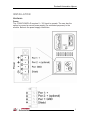
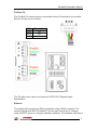
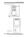
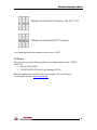
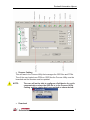
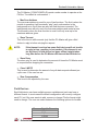
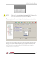
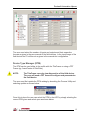
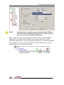
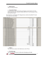
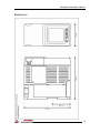
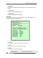
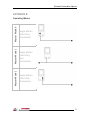
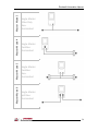
Rockwell Automation Hiprom
1788HP-EN2PA-R
USER MANUAL
V1.00.04
Section
Page
INTRODUCTION
2
INSTALLATION
3
HARDWARE
3
SOFTWARE
6
SETUP
7
RSLOGIX
7
FIELD DEVICES
10
DEVICE TYPE MANAGER (DTM)
12
OPERATION
14
RSLOGIX
14
WEB INTERFACE
17
SPECIFICATIONS
19
ELECTRICAL
19
MECHANICAL
20
APPENDIX
21
A – DISPLAY STATUS
21
B – OPERATING MODES
25
1
Rockwell Automation Hiprom
INTRODUCTION
The 1788HP-EN2PA-R provide a fast and integrated solution for adding Profibus
PA field devices to any Logix platform. This linking device provides a direct link
between Profibus PA and EtherNet/IP with no intermediate Profibus-DP layer
required.
Integration into RSLogix5000 is seamless when making use of the modules' AddOn-Profiles (AOPs), and the process variables of each field device appear in
engineering units without any required user logic. The entire Profibus PA
configuration is done within the RSLogix5000 environment. Additional PV
statuses and diagnostic information is also available.
The module supports a maximum of 24 field devices and can supply a 500mA
per trunk.
It will also allow the user to view detailed diagnostics from each field device using
its DTM (device type manager) directly from the Logix environment with Hiprom’s
FDT-ThinFrame. The user will be able to view a scope trace of the signal of each
field device and provide extended statistics with regards to packet count (send,
received, class 1, class2 etc.)
2
Rockwell Automation Hiprom
INSTALLATION
Hardware
Power
The 1788HP-EN2PA-R requires 9 – 32V input to operate. The user has the
option to connect a second power supply (for redundant purposes) to the
module. Below is the power supply connection:
3
Rockwell Automation Hiprom
Profibus PA
The Profibus PA network must be connected via the PA terminal on the module.
Below is the pin-out is as follow:
Pin
Description
Right
PA +
Middle
PA -
Left
Shield
The PA cable color code is used as set in IEC61158-2 Physical Layer
Specification.
Ethernet
The module will connect to an Ethernet network using a RJ45 connector. The
module will ship with BOOTP enabled. Thus the user can set the IP address
using a BOOTP server or using the hardware switches. The hardware switches is
4
Rockwell Automation Hiprom
located under the front cover as shown below. The Page button is used to toggle
between different diagnostics on the display.
5
Rockwell Automation Hiprom
Module will boot with IP address: 192.168.1.123
Module will boot with BOOTP enabled
For normal operation the switches must be set to “000”.
Software
The user will need the following software to configure and use the 1788HPEN2PA-R:
• Add-on Profile (AOP)
• 1788HP-EN2PA-R Device Type Manager (DTM)
Both the applications can be found on the product CD or the Hiprom
Technologies website: www.hiprom.com
HU
U
6
Rockwell Automation Hiprom
SETUP
RSLogix
The module must be added to the IO tree of the Logix Controller in RSLogix
before the user can configure the device. To add the 1788HP-EN2PA-R the user
must select the module when adding it under a Allen-Bradley Ethernet bridge
(eg. EN2T) as shown below:
When added the module requested packet interval (RPI) will default to 300ms. If
needed the user can change this depending on the field device count and update
times required.
NOTE:
The RPI will determine the amount of Class 1 data requests
send for the field devices configured on the PA Bus. Thus if
there are many field devices configured on the bus and the RPI
is set too low, the field devices will not be able to update in
time and all acyclic PA data will be slow as Class 1 data is
prioritized. Please see Class 2 MPPF in the master
configuration.
Once the module is added to the tree the user can open the properties by rightclicking on the device and selecting the Properties option. Once the properties
window is open select the Configuration tab to open the 1788HP-EN2PA-R
configuration page as shown below:
7
Rockwell Automation Hiprom
• Process Catalog
This will launch the Process Utility that manages the GSD files and DTMs.
Thus if the user loaded new DTMs or GSD files the Process Utility must be
launched and the libraries must be updated.
NOTE:
•
The user will not be able to configure a field device for cyclic
communication unless the GSD file is in the Process Utility
Catalog and the catalog has been updated as shown below:
Download
8
Rockwell Automation Hiprom
Once the user is happy with the configuration it can be downloaded to the
1788HP-EN2PA-R. The device will save the configuration in non-volatile
memory. If the power is cycled then the module will use the last configuration
saved.
NOTE:
Any changes will only take effect once it has been downloaded
to the 1788HP-EN2PA-R module.
• Upload
If the user does not have the configuration of the 1788HP-EN2PA-R it can be
uploaded and saved in the RSLogix project.
NOTE:
The configuration will only be saved in the RSLogix project if
the user has pressed the Apply button in the AOP.
• Scan
The scan function is used to find the field devices on the local PA bus and
apply a default configuration to each one according to the manufacturers
GSD file. The AOP will scan up to the Max Scan Address (configured in
Master config).
• Add Device
The user can also add a device manually is for example the device is not
currently connected. As a device is selected the same default configuration is
done to the field device configuration.
• Copy Device
In the case where the user has setup a field device in a specific way and
there are lots of the same devices in the same tree the user might want to
copy the current field device to all the other locations instead of having to
setup each field device from scratch.
• Delete Device
If a device need to be deleted from the tree the user will use this command.
• Delete All
This is used to remove all field devices from the configuration.
PA Master Configuration
• Topology Mode
The user must select the correct topology mode for the application. The
graphical representation must be used to match the topology.
•
PA Node
9
Rockwell Automation Hiprom
The PA Master (1788HP-EN2PA-R) needs a node number to operate on the
PA Bus. The default is node number 1.
• Max Scan Address
The max scan address is used for one of two functions. The first is when the
module is operating it will constantly “ping” each node number in the
background as to see if there are any new field devices connected. The
background scan will only run to the max scan address and restart at one.
The second is when the scan function is used it will only scan up to the
maximum address given.
• Slave Timeout
This is the time in milli-seconds (ms) that the PA Master will give a field
device to reply in before retrying the request.
NOTE:
If the timeout is set too low some field devices will not be able
to reply in time, resulting in lost packets. If the timeout is set
too big then if a field device has gone offline it might take a
long time before the PA Master will timeout that field device.
• Slave Retry
The slave retry is used to determine the amount of times the PA Master must
re-request before dropping the connection.
• Class 2 MPPF
This is used to determine the amount of acyclic data requests allowed per
cyclic scan. If the user has set
• Slew Compensation
This is not to be adjusted by the user.
Field Devices
Each field device can have multiple process variables and each can have a
different format. In most cases the default configuration will correctly configure
each PV, but if the user wants to add, remove or change PVs the format might
need to change. The user can select between the following options for formats:
Process Variable Format
1 Byte
2 Bytes
3 Bytes
10
Rockwell Automation Hiprom
4 Bytes
Real
1 Byte with Status
2 Bytes with Status
3 Bytes with Status
4 Bytes with Status
Real with Status
NOTE:
If the user is not certain about the format of the PV please refer
to the user manual of the field device being used.
The user can choose the format clicking on the drop-down menu and selecting
as shown below:
In some cases (eg. Positioner field devices) there are multiple input and output
PVs per slot. The user will then manually need to configure the format for the
slot. This is done be selecting the Manual Config tick box and clicking the
configure button as shown below:
11
Rockwell Automation Hiprom
The user must select the number of inputs and outputs and their respective
formats as given in the user manual of the field devices. In the input image of the
field device the PV will be set as given in the manual slot configuration.
Device Type Manager (DTM)
The DTM can be used either in the profile with the ThinFrame or using a FDT
Frame (eg. AssetCentre of FieldCare).
NOTE:
The ThinFrame can only view diagnostics of the field device.
The user will need a FDT frame to configure and parameterize
the field device.
The user must first update the DTM catalog by launching the Process Utility and
selecting update as shown below:
Once this is done the user can select the DTM in the AOP by simply selecting the
correct DTM given and select open as shown below:
12
Rockwell Automation Hiprom
NOTE:
Sometimes the user will be presented with multiple DTMs of
the same device but different revisions. The user must select
the correct one for the specific field device.
When using a FDT Frame the user will first need to add the Comm DTM HS
Ethernet/IP. Under this Comm DTM the user must the select the 1788HPEN2PA-R channel DTM. The user will need to configure the IP address and Max
Scan Address. Once this is done the user can access field devices or the PA
Master diagnostics as given in the profile:
13
Rockwell Automation Hiprom
OPERATION
RSLogix
Each 1788HP-EN2PA-R consumes a total of 4 connections from the Logix
Controller regardless of the field device count. Thus the input and output image
of each 1788HP-EN2PA-R is divided into four sections A to D. The first
connection will have the PA Master Data added as well. Below is the input image
of the PA Master:
• Bus A/B Tripped
If too much current has been drawn (> 500mA) on either Bus A or Bus B it will
trip can the bus will no longer be functional. It will then be indicated in the
input image.
• NewFieldDevice
If a new field device is found which is not in the configuration of the PA
Master the new field device bit will be set.
• MultiMasterActive
Once the two PA Master modules have sync’d and they have the same node
number as well as the same configuration then this bit will be set.
NOTE:
Both PA Masters must have exactly the same configuration
(master and field devices) for the masters to be able to sync.
• MasterMode
This will give the current topology implemented. Please view Appendix B.
14
Rockwell Automation Hiprom
• ModuleStatus
This is currently reserved.
• Connection Status
If a field device is online and running (exchanging cyclic data) then its field
device index bit in (the connection status) will be set. If the device goes offline
the bit will be cleared.
Each field device will display its PA diagnostics as well as all available PVs and
their status as shown below:
• PANode
This is the node number of the field device on the PA bus.
• OnlineRunning
This is set when the device is online and exchanging cyclic data.
15
Rockwell Automation Hiprom
• ConfigFault
If there is a fault in the configuration of the field device then this bit will be set.
• ExtDiagAvail
When the field device has extra extended diagnostics available then this bit
will be set. Note that this bit can be dynamic.
• ParameterFault
If there is a fault in the parameterization of the field device then this bit will be
set.
• ParameterReq
If the device has not been received its parameterization this bit will be set.
• FreezeMode
If the user has enabled freeze mode in the parameterization of the field
device and a global control has been sent to freeze the device PVs this bit will
be set.
• SyncMode
If the user has enabled sync mode in the parameterization of the field device
and a global control has been sent to sync the device PVs this bit will be set.
• WatchDog
If the watchdog has been enabled in the parameterization of the field device
this bit will be set.
• PAIdent
This is the ident number of the specific field device.
• PVReal1 – PVReal8
If the user has set a process variable to be a Real format the user will find the
data in this section.
• PVStatus1 – PVStatus8
If the user has set a process variable to have a Status the user will find the
status value for the each PV in this section.
NOTE:
The definition of the PV Status can be found in the user
manual of the field device. In general a value of below 40h
indicates that the PV is bad, a value of between 40h and 7Fh
indicates that the PV value is uncertain and a value of above
80h indicates that the PV value is good.
16
Rockwell Automation Hiprom
• PVInt1 – PVInt8
If the user has set a process variable to be a 1Byte to 4 Byte format the user
will find the data in this section.
• PVInt1 – PVInt8
If the user is using a field device that requires an output the data must be
updated in the output image of that field device. If a real value must be sent
then use a copy function to update the PVInt.
NOTE:
Please refer to the example code for a detailed example on
how to update data for output modules.
• PVStatus1 – PVStatus8
If the user has set a process variable to be a 1Byte to 4 Byte format the user
will find the data in this section.
NOTE:
Some field devices will only operate correctly once a valid
Status (for example 80h) is sent with the process variable.
Web Interface
The web interface can be used from any PC that has a web browser. It will
provide all the diagnostics of the module as well as each field device as shown
below:
17
Rockwell Automation Hiprom
The web interface can be accessed by entering http:// IP address into the
address bar of the browser as shown below:
Eg. 1788HP-EN2PA-R IP address:
196.135.145.234
18
Rockwell Automation Hiprom
SPECIFICATION
Electrical
specification
Power Requirements
Power Consumption
value
Power will be connected to the 1788HP-EN2PA-R using the 4 way
phoenix connector.
Operating Voltage: 24 to 32 V
260 mA at 24 V (with no field devices attached)
NOTE: The CN2PA-R must be powered by a SELV *(Separated Extra
Low Voltage) power supply limited to 8A or being protected by a 5A fuse.
PA Bus current supply
500 mA at 24 V (per trunk)
Operating / Storage
Temperature
0 to 50 ºC
Pollution Degree
2
Relative Humidity
5 to 95 % non-condensing
Operating Shock
Storage Shock
Vibration
Emissions
ESD Immunity
Radiated RF Immunity
EFT/B Immunity
Conducted RF Immunity
Enclosure Type Rating
IP20
Power Conductors
18 AWG (0.75 sq.mm) maximum, 24 AWG (0.25 sq.mm) minimum
copper wire
Ethernet Conductor
CAT5 STP
Profibus PA Conductor
18 AWG (0.75 sq.mm) maximum, 24 AWG (0.25 sq.mm) minimum
copper wire
Connector Tightening Torque
(0.22 Nm -> 0.25 Nm)
19
Rockwell Automation Hiprom
Mechanical
20
Rockwell Automation Hiprom
APPENDIX A
Display Status
The display of the 1788HP-EN2PA-R will provide certain diagnostics to the user.
Below are the various screens:
Main
The main screen will always be displayed unless the user has toggled to another
screen. If the user has not toggled the screen again after 10 seconds it will
default back to this screen.
• PA Bus A/B:
This is the voltage of each bus.
• IP:
This is the current IP address set. If BOOTP has been enabled this will
indicate BOOTP.
• STS:
This will show the current module status.
ok
new device found
No events
A new field device is on the bus
21
Rockwell Automation Hiprom
redundancy ok
redundancy err
bus A tripped
bus B tripped
SAFE MODE
Masters are sync’d
The master modules are out of sync
PA Bus A has tripped because of over
current
PA Bus B has tripped because of over
current
The module has been set into safe
mode
• Field Device Success
Below is the definition of the field device summary. The success rate is the %
of packets send to packets received.
Display
% of packets received
95+
80+
70+
60+
50+
Below 50
Unknown
PA Master
If the Page button is pressed the first screen is the PA Master screen as shown
below:
22
Rockwell Automation Hiprom
• Bus A/B:
First the PA Bus voltage is displayed followed by the current being drawn on
that bus.
• Temperature:
This is the internal module temperature.
• External Pwr:
This is the external power feed voltage.
Field device
As the Page button is pressed from the PA Master screen, field device 0 to 23
will display it diagnostics as given below:
• PANode
This is the node number of the field device on the PA bus.
• Ident
This is the ident number of the specific field device.
• Status:
This will show the current module status.
Not Connected
The device can not be seen
23
Rockwell Automation Hiprom
Online
ConfigRunning
N/A
The device is online but not configured
The device is configured and
exchanging data
The device has not been added to the
configuration
• Success
The packets send vs received success percentage of the last 100 packets.
• Pckt Send:
The total amount of packets sent.
• Pckt Recv:
The total amount of packets received.
• Bad CRC:
The total amount of bad CRC packets received.
• No Reply:
The total amount of requests that did not receive a reply.
24
Rockwell Automation Hiprom
APPENDIX B
Master Mode 0
Single Master
A Bus Only
Terminated
Master Mode 1
Single Master
A Bus Only
NonTerminated
Master Mode 2
Operating Modes
Single Master
B Bus Only
Terminated
25
Master Mode 3
Single Master
B Bus Only
NonTerminated
Master Mode 4
Single Master
Dual Bus
Terminated
Master Mode 5
Single Master
Dual Bus
NonTerminated
Master Mode 6
Rockwell Automation Hiprom
Single Master
Split Bus
Terminated
26
Master Mode 7
Single Master
Split Bus
NonTerminated
Master Mode 8
Single Master
Ring Bus
Master Mode 9
MultiMaster
A Bus Only
Terminated
Master Mode 10
Rockwell Automation Hiprom
MultiMaster
A Bus Only
Shared
Termination
27
Master Mode 11
MultiMaster
A Bus Only
Not Terminated
Master Mode 12
MultiMaster
B Bus Only
Terminated
Master Mode 13
MultiMaster
B Bus Only
Shared
Termination
Master Mode 14
Rockwell Automation Hiprom
MultiMaster
B Bus Only
Not Terminated
28
Master Mode 15
MultiMaster
Dual Bus
Terminated
Master Mode 16
MultiMaster
Dual Bus
Shared
Termination
Master Mode 17
MultiMaster
Dual Bus
Not Terminated
Master Mode 18
Rockwell Automation Hiprom
Listen Only
Dual Bus
Not Terminated
29
Rockwell Automation Hiprom
HIPROM
TEL: +27 11 787 4458
FAX: +27 11 787 7937
POSTAL
P.O. Box 732
Pinegowrie
South Africa
2123
PHYSICAL
369 Pretoria ave
Ferndale, Randburg
South Africa
30