1
MKIV Coded Wire Tag Injector
Instruction Manual
Northwest Marine Technology, Inc.
Shaw Island, Washington 98286, U.S.A.
Phone: (360) 468-3375
Web:
www.nmt.us
December 1, 2014
3.23
Table of Contents
1 Introduction........................................................................................................... 1
2 Assembly and Setup ............................................................................................ 3
Contents Checklist ............................................................................................................ 3
Assembly .......................................................................................................................... 3
Quick Start ........................................................................................................................ 5
3 Getting Ready To Tag .......................................................................................... 7
Needle Selection ............................................................................................................... 7
Needle Positioning Jig Selection ....................................................................................... 7
Tag Length........................................................................................................................ 8
Common Menu Settings.................................................................................................. 10
Needle Penetration ......................................................................................................... 10
Tag Placement Depth ..................................................................................................... 10
Final Check ..................................................................................................................... 11
4 Configuration ...................................................................................................... 13
Keyboard ........................................................................................................................ 13
Key: [TOTAL] ............................................................................................................................... 14
Key: [BATCH] ............................................................................................................................... 14
Key: [CLEAR] ............................................................................................................................... 14
Key: [BATT] .................................................................................................................................. 14
Key: [LOAD] ................................................................................................................................. 15
Key: [SHOW] ................................................................................................................................ 15
Key: [*] .......................................................................................................................................... 16
Key: [-10], [+10], [-1], [+1] ............................................................................................................ 16
Key: [TAG] .................................................................................................................................... 16
Key: [ESC]ape .............................................................................................................................. 16
Key: [OK] ...................................................................................................................................... 17
Key: [STEP] .................................................................................................................................. 17
Adjustment Menu ............................................................................................................ 18
Key: [ADJ] .................................................................................................................................... 18
Item: SETUP ............................................................................................................................................ 19
Item: TAG LEN ........................................................................................................................................ 19
Item: WIRE .............................................................................................................................................. 20
Item: QCD THRESH ................................................................................................................................ 20
Item: STOP .............................................................................................................................................. 21
Item: NEEDLE MOV ................................................................................................................................ 22
Item: MIN. TIME....................................................................................................................................... 22
Item: QCD BEEP ..................................................................................................................................... 23
Item: QCD DELAY ................................................................................................................................... 23
Item: CUT EDGE ..................................................................................................................................... 23
Item: TAG CREDIT .................................................................................................................................. 24
Item: US-EUR .......................................................................................................................................... 24
5 Quality Control Device (QCD) ............................................................................ 25
Overview ......................................................................................................................... 25
Assembly ........................................................................................................................ 26
General Assembly ........................................................................................................................ 26
Mechanical Diverter Gate Assembly ............................................................................................ 28
Separator (Water) Jet Adjustments .............................................................................................. 30
6 Maintenance ........................................................................................................ 33
Injector Disassembly ....................................................................................................... 33
MKIV Manual
Table of Contents
i
Injector Assembly ............................................................................................................ 35
Parts Inspection............................................................................................................... 38
Needle .......................................................................................................................................... 38
Background ..............................................................................................................................................38
Needle Inspection, Reaming and Sharpening ..........................................................................................38
Cutter ............................................................................................................................................ 39
Background ..............................................................................................................................................39
Cutter inspection ......................................................................................................................................40
Needle Carrier .............................................................................................................................. 41
Drive Roller................................................................................................................................... 42
Touch Switch ................................................................................................................................ 42
Background ..............................................................................................................................................42
Cleaning ...................................................................................................................................................42
QCD Solenoid Valve .................................................................................................................... 42
Background ..............................................................................................................................................42
Removal and Installation ..........................................................................................................................43
Solenoid Valve Cleaning ..........................................................................................................................43
QCD Filter Assembly .................................................................................................................... 44
Background ..............................................................................................................................................44
Filter Cleaning ..........................................................................................................................................44
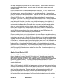
Cleaning Protocol ............................................................................................................ 45
Equipment and Supplies .............................................................................................................. 46
Injector.......................................................................................................................................... 46
Quality Control Device (QCD) ...................................................................................................... 47
Other tagging protocol .................................................................................................................. 48
Procedures Involving Tagging Trailers ........................................................................................ 48
7 Appendices ......................................................................................................... 49
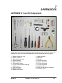
Appendix A: Tool Kit Components ................................................................................... 49
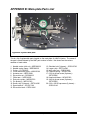
Appendix B: Main-plate Parts List .................................................................................... 50
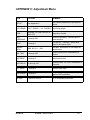
Appendix C: Adjustment menu ........................................................................................ 51
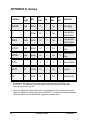
Appendix D: Setups ......................................................................................................... 52
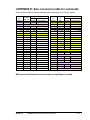
Appendix E: Size conversion table for salmonids ............................................................ 53
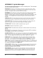
Appendix F: System Messages ....................................................................................... 54
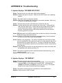
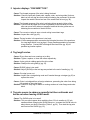
Appendix G: Troubleshooting .......................................................................................... 55
Appendix H: Spare Parts and Accessories ...................................................................... 66
Appendix I: Specifications................................................................................................ 67
8 Contacting NMT ................................................................................................... 69
INDEX ...................................................................................................................... 71
ii
Table of Contents
MKIV Manual
1
INTRODUCTION
Northwest Marine Technology (NMT) designs and manufactures Coded Wire Tags, Injectors
and Detectors. The decimal coded wire tag (DCWT) identification system provides an
accurate and versatile method for assessing and researching both natural populations and
hatchery reared animals. Coded Wire Tags have been implanted in hundreds of different
marine and freshwater species. Reliability of the equipment and data allow for application in
many areas of fisheries research and management.
The Model MKIV Tagging Unit is designed to give years of reliable performance. Please
take time to read and understand the operating and maintenance instructions so you can
obtain the maximum service from this product. Manuals for all NMT products can be
downloaded at www.nmt.us/support/manual.htm.
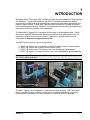
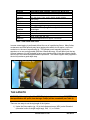
The MKIV Injector comes in various configurations:
1.
2.
3.
4.
MKIV Tag Injector only (a V-detector or Wand for quality control is recommended).
MKIV Tag Injector with a Quality Control Device (QCD)
MKIV Tag Injector with a T4 Detector (refer to the T4 Detector User’s Manual)
MKIV Tag Injector in an AutoFish trailer (refer to the AutoFish SCT Operator Manual).
Note: Model MKIV Tag Injectors and QCDs cannot be interchanged with earlier models
MKI, MKII or MKIII equipment.
MKIV in the AutoFish Trailer
MKIV Tag Injector and QCD
The MKIV Tagging Unit is backed by a 1 year parts and labor warranty. NMT takes great
pride in providing the best customer service and your complete satisfaction is important.
Please contact us whenever you have questions or comments about our products.
MKIV Manual
INTRODUCTION
1
2
ASSEMBLY AND SETUP
CONTENTS CHECKLIST
A MKIV Tag Injector is shipped with the following items in a transit case.
o MKIV Tag Injector
o Power Supply
o Touch Switch (or optional Foot Switch)
o 3 non-custom head molds
o 3,000 tag spool of test wire
o Tool Kit (components are shown in Appendix A)
o Instruction Manual
A MKIV Tagging Unit includes these additional items in a second transit case.
o Quality Control Device (QCD)
o Interconnect Cable
o Funnel
o Quick disconnect with a water filter
Make certain all the above items are present. Remove all items from the boxes and make
sure nothing has been left in the packing materials.
ASSEMBLY
Place the Injector on a stable flat surface near the power source. The tagging equipment
operates on 12-28 volts DC (approximately 50 watts). The Injector comes with a power
supply which converts 110-240 volts AC to 24 volts DC. Plug the power supply into a
grounded AC power outlet. If you have any uncertainty about whether the outlet is
grounded, verify that the outlet is grounded before proceeding. Alternate DC power sources
such as a 12 volt automobile battery can also be used when AC power is not available.
Appropriate adapters for use with alternate power sources are available from NMT.
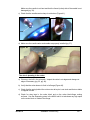
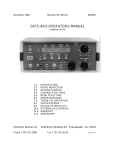
1) The Injector has a built-in circuit breaker (Figure 1) and protective fuse. If the circuit
breaker is tripped the Injector will shut off. The circuit breaker will automatically reset
after about one minute. If the circuit breaker does not reset, the internal protective fuse
is most likely blown and the Injector must be returned to NMT for servicing.
2) Connect the cable from the power supply to the 4 pin connector at the rear of the Injector
(Figure 1).
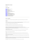
WARNING! DO NOT attach the QCD while the Injector is turned on to avoid
DAMAGING the internal electrical components!
3) The Touch Switch consists of a square metal block, push button and a cable (pg 42).
Attach the cable to either of the two large connectors on the back of the Injector.
Connect the QCD (if present) to the other large connector.
4) See page 26 for additional QCD assembly and setup if applicable.
MKIV Manual
ASSEMBLY AND SETUP
3
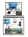
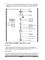
Figure 1a: Injector – Rear view
On/Off Switch and
circuit breaker
Power Supply
QCD
Interconnect
Cable
Touch Switch
Note: The two large connectors on the back of the Injector are interchangeable. Keep the
protective caps closed on any unused connector(s).
Figure 1b: Cable connections for a mechanical gate QCD
MKIV Injector
Touch Switch
110-220 VAC
24 VDC
Power
Supply
Gate Actuator
Separator
QCD Electronics Box
4
ASSEMBLY AND SETUP
QCD Detection Head
Gate Box
MKIV Manual
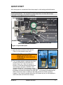
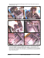
QUICK START
After the equipment is assembled follow these steps for initial testing and familiarization.
Note: These steps are intended to confirm that the equipment is operating and ready for the
remaining adjustments. The completion of these steps does not mean that all steps
necessary to start tagging have been completed.
NEEDLE CARRIER
CLAMP
CUTTER BLOCK
WIRE GUIDE
CUTTER
SPOOL RETAINER
DRIVE ROLLER
ENTRY WIRE GUIDE
ACTUATOR ARM
NEEDLE CARRIER
DRIVE ROLLER LATCH
IDLER ROLLER
SHOULDER BOLT
E-CLIP
MAGNETIZER
PRESSURE SPRING
IDLER ROLLER ARM
Figure 2: Injector Main-plate
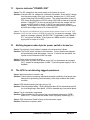
1) Open the latch on the front of the Injector
(Figure 1c) and swing the door open.
WARNING: DO NOT attach the QCD while the
Injector is turned on or risk
DAMAGING the internal electrical
components!
Figure 1c
LED
Door
Latch
LED
Head
mold
base
2) Turn on system power by pressing the rubbercovered On/Off button on the back of the
Injector (Figure 1a). When the Injector is
turned on, a self-test sequence will take place
Blue Tag Switch
and the display will show a "READY VX.X"
message where “X.X” is the firmware version
number. If a QCD is not connected, or if the self-test detects a problem with the QCD,
the display will show the message "NO QCD OK?". If you see this message and the
QCD is connected, check to make sure the QCD Interconnect Cable is properly
installed. If you intend to operate without the QCD press any key on the keyboard to
confirm this status and clear the message.
MKIV Manual
ASSEMBLY AND SETUP
5
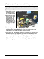
3) The Injector is shipped with a spool of test wire installed. If there is not a spool of wire
on the machine, install one on the spool retainer before proceeding.
Note: The MKIV Injector ships with a 2.5 inch needle installed which is protected by a head
mold base (Figure 1c). If a needle is not installed or a 3.5 inch needle is required, refer to
pg 37 on how to properly install a needle.
4) Locate the idler roller arm
and move the drive roller
latch so that the rollers
are engaged (Figure 2b).
Figure 2b: Loading Tag Wire
5) Now load the tag-wire by
pressing [LOAD] (pg. 15)
on the keyboard. The
display will show the
message “LOAD 100"
and the drive rollers can
be rotated easily by hand.
The Injector may make a
hissing sound when in
the LOAD position. This
is normal.
Tag Wire
Drive Roller
rotate
Engage the
Drive Roller
Latch
6) Insert the tag-wire into
the entry wire guide and
push it forward until it reaches the drive rollers. Rotate the top roller clockwise by hand
to feed the wire into the cutter block wire guide (Figure 2b). Continue turning the top
roller until the tag wire extends slightly beyond the tip of the needle.
7) Press the [OK] key. The Injector will retract and cut the tag wire. Cycle the Injector once
by pressing either the Touch Switch button, the [TAG] key, or the blue tag switch on the
front of the Injector if equipped (Figure 1c). Any of these three switches will cycle the
Injector. The first piece of wire ejected will be longer than a standard tag. Cycle the
Injector a few more times to see how it operates and confirm the Injector is making the
proper length tags. Each cycle will produce one tag. If a QCD is attached, the red error
light and tone will be activated as determined by the Tag Credit value (pg. 24). This
indicates that tagged specimens are not being detected by the QCD, and is normal for
this sequence.
6
ASSEMBLY AND SETUP
MKIV Manual
3
GETTING READY TO TAG
Before tagging, please read NMT’s Coded Wire Tag Project Guide included with your
MKIV Tag Injector or downloaded from www.nmt.us. It provides a comprehensive overview
of coded wire tagging projects and discusses appropriate setups for a variety of species and
environments.
The following MKIV Tag Injector adjustments need to be made or checked before tagging:
§
§
§
§
§
§
Needle selection
Positioning jig selection (for example a head mold)
Tag length (pg 19)
Common Menu Settings
Needle penetration
Tag placement depth
If you are using a Quality Control Device (QCD) you will also check or adjust:
§
§
§
§
§
Water flow (both versions) (pg. 26)
Separator jets (water jet version only) (pg. 30)
Mechanical gate (mechanical gate version only) (pg. 28)
QCD delay (pg. 23)
QCD Threshold (pg. 20)
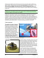
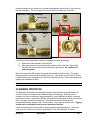
NEEDLE SELECTION
Figure 3: Needle styles
Four needle styles are offered for the MKIV Tag
Injector:
·
·
2.5 inch (63.5 mm) etched or non-etched
3.5 inch (89 mm) etched or non-etched
Non-etched needles do not have a reduced outside
diameter near their tip, making them better suited for
larger animals or tagging into harder locations
because of their added strength. Etched needles
have a reduced outside diameter near the tip,
making them better suited for smaller animals,
where a smaller incision is required or for tagging
into soft tissue. The trade off with etched needles is
reduced strength in the tip.
Non-etched
Etched
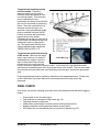
NEEDLE POSITIONING JIG SELECTION
The most common type of positioning jig used with a MKIV Tag Injector is the head mold.
NMT sells head molds for a wide variety of size and species fish (see Table 1). A custom
head-mold kit is also available from NMT to allow the end user to create unique head molds.
MKIV Manual
GETTING READY TO TAG
7
Species
Head Mold Size (fish/lb); CMS=Closed Mouth Style
coho/Chinook
Steelhead
(Rainbow)
Pink
Atlantic Salmon
Lake Trout
Chum
5, 10, 15, 20, 30, 45, 65, 90, 120, 200, 300 (CMS), 550, 1100
Species
2(5), 3(8), 5(12), 7(18), 11(27), 20(50), 36(90), 80(200)
2000 (CMS)
7, 9, 11, 15, 25, 30, 50, 100, 120
5, 8, 12, 18, 27, 50, 90
700
Head Mold Size (length in mm); CMS=Closed
Mouth Style
Sockeye
Walleye
Mullet
Paddlefish
60 (CMS), 90
55, 65, 125
60-70, 70-80, 100, 120, 140
Not Size designated but for approx. a 6 inch fish
Table 1: NMT head mold sizes
In some cases tagging is performed without the use of a positioning fixture. Many fishes,
crustaceans and other animals may have tagging sites which do not require, or are not
conducive to, the use of a positioning jig. The operator would manually impale the
specimen on a non-moving needle (see Item: Needle Move pg. 22) and then inject the tag.
In these instances it is still desirable to have some depth control so that the operator knows
how much of the needle has penetrated the specimen. The needle support tube (supplied in
the tool kit) makes a good depth stop.
Figure 4a: Positioning Jigs
Needle support tube
Head mold
TAG LENGTH
WARNING: If the tag length of the MKIV Tag Injector is set to cut tags SHORTER than
that specified on the spool, then the tags’ code(s) will be unreadable (see Table 2).
There are two ways to set the tag length of the Injector:
1) Under the Setup option (pg. 19) in the Adjustment menu (ADJ), select Standard
(otherwise known as single length tags), Half, 1 ½, or Double.
8
GETTING READY TO TAG
MKIV Manual
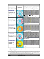
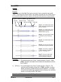
Table 2: Coded Wire Tag formats
DCWT Format and
MKIV Injector setting
Spool Label
Layout: If a 2 mm piece of wire were unrolled
and magnified, it would look like this. The
yellow bars show where tags of each format
would be cut by the MKIV Tag Injector.
Standard DCWT:
TAG LEN [SGL] (pg
19 ) or
SETUP [STANDARD]
(pg 19)
Tag Length
Tag cut off
Agency Code
Sequential DCWT:
TAG LEN [SGL] or
SETUP [STANDARD]
Sequence
Agency DCWT:
TAG LEN [SGL] or
SETUP [STANDARD]
Tag format
½ Length DCWT:
TAG LEN[1/2] (pg 19 )
or
SETUP[HALF] (pg 19 )
Quantity
1 ½ Length DCWT:
Data 2
TAG LEN[1 1/2]
(pg 19) or
SETUP[1 1/2] (pg 19 )
Data 1
2) Choose the appropriate tag length in the Adjustment menu under the option
TagLength (pg. 19).
Note: Using the TagLength option will automatically display Special if other options, for
example Needle Move, are changed in the Adjustment menu. One can also store 2
different adjustment settings using Custom1 and Custom2 (pg. 19).
MKIV Manual
GETTING READY TO TAG
9
COMMON MENU SETTTINGS
1) Using a head mold and 2.5 inch needle:
· Setup [STANDARD/HALF/1 1/2] (pg 19)
· Show [96] (pg 15)
2) Using a needle support tube and a 3.5 inch needle:
· Setup [SPECIAL/CUSTOM 1/CUSTOM 2]
· Needle Move [NO] (pg 22)
· Stop [1] (pg 21)
· Show [171]
3) *Using a needle support tube and a 3.5 inch needle:
· Setup [SPECIAL/CUSTOM 1/CUSTOM 2]
· Needle Move [S5-S23]
· Stop [2], the needle starts in the extended position.
· Min. Time [0-255] (pg 22)
· Show [172-180] , dependent on the amount of Needle Move.
*This setup using Stop 2 and a small amount of Needle Move is recommended over
no Needle Move (common setup 2) and a Stop of 1 if poor tag retention is an issue.
NEEDLE PENETRATION
Needle penetration refers to the depth the needle will penetrate into the specimen. Proper
penetration depth is very important for tag retention and depends on the size and species of
the specimen being tagged. Penetration depth is controlled with the use of a head mold or
positioning jig.
To set the needle penetration depth, put the Injector in the SHOW mode which will move the
needle to its fully extended position. Loosen the set screws in the head-mold holder and
slide the appropriate head mold/needle positioning jig in or out to adjust the distance the
needle will extend into the specimen. Gently tighten the set screws to hold the head mold in
place.
TAG PLACEMENT DEPTH
Tag placement depth refers to the position of the tag with respect to the tip of the needle.
Tag placement depth can be estimated by measuring the distance from the end of the wire
to the surface of the head mold while the Injector is in SHOW mode (pg. 15). In all cases
correct tag placement depth must be confirmed by dissection of tagged test specimens.
Figure 4b shows the preferred placement for DCWT in salmonids.
Note: In the SHOW mode, the tip of the uncut tag wire will move to the same position as the
leading end of the tag at implantation. Thus, the end of the uncut tag wire represents the
tag's deepest point of penetration.
There are instances when the tag must be extended beyond the tip of the needle, and other
cases when the tag should not be extended beyond the tip of the needle. Examples of
these cases are given below.
10
GETTING READY TO TAG
MKIV Manual
Tag placement depth beyond the
tip of the needle: There are
instances when you may wish to
manually impale the specimen on a
non-moving needle. This technique
can be used when the tag
implantation site does not lend itself to
the use of a head mold or positioning
fixture. Since the needle will not be
retracting to leave the tag in the
specimen, the tag implantation depth
must be modified using the SHOW
function so that the tag is delivered
beyond the tip of the needle.
Otherwise the tag will not reach the tip
of the needle until additional tags from
subsequent Injector cycles force it
out. The approximate SHOW value
using a standard length needle with
"NEEDLE MOVe (NO)" is 78.
Figure 4b: Typical Tag Placement - Salmonid
Tag placement depth behind the tip
of the needle: Whenever the target
Coded Wire Tag
area is very hard (e.g., the head of
steelhead trout), trying to inject the
tag into tissue which has not been
penetrated by the needle itself will
cause a wire jam or slippage of the drive rollers. In this case use a tag placement depth
which does not extend any part of the tag beyond the tip of the needle. This way the needle
can penetrate the hard tissue and, upon retracting, leave the tag in a previously penetrated
area.
Proper tag placement must be verified by dissection of the tagged specimens. Please refer
to the Coded Wire Tag Project Manual for more details about ensuring correct tag
placement.
FINAL CHECK
As a review, see that the following items have been considered and checked before tagging
begins.
·
·
·
·
·
·
Proper spool of wire is loaded (pg 6) .
Tag length set to correspond to tag format (pg. 19).
Tag target chosen for specimen.
Head mold or positioning fixture and injection technique determined.
Needle penetration and tag placement depth set and tested.
QCD water flow and mechanical gate (or jet position) adjusted (pg. 25).
MKIV Manual
GETTING READY TO TAG
11
4
CONFIGURATION
KEYBOARD
The keyboard on top of the Injector is used to make nearly all operating adjustments and to
obtain system information. All items displayed when using the keyboard are kept in circular
lists. This means that as you proceed through the choices, after the last item is displayed
the first item is displayed again. This section describes each key, its function and
corresponding displays/options.
Explanations of the keyboard and its functions use the following conventions:
[]
""
()
Names of keys are shown in square brackets.
Display messages are shown in quotes.
Changeable values are shown in parentheses.
Figure 5: Display and Keyboard
Display
Unmarked button performs the same
function as the [BATCH] key.
Keyboard
Key
MKIV Manual
CONFIGURATION
13
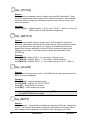
Key: [TOTAL]
Purpose:
To display the non-resettable counts of Injector cycles and QCD activations. These
counts are retained even with the power off for the life of the Injector. Non-resettable
counts are useful for keeping a maintenance record on items such as cutters, drive
rollers and needles.
Operation:
Press [TOTAL] -- toggles between "T INJ x" and “T QCD x” where x is the total
Injector cycles or QCD activations, respectively.
Key: [BATCH]
Purpose:
To display the resettable counts of Injector cycles, QCD activations, and the net
difference, called rejects, between the two. Batch may be used to keep track of items
such as activity per hour, day, group, etc. There is an unlabeled key next to the
display which functions identically to the [BATCH] key, and can be used with the
keyboard cover closed. To reset the batch counts see the explanation for the
[CLEAR] key.
Operation:
Press [BATCH] -- displays "INJ x", x = the number of Injector cycles.
Press [BATCH] -- displays "QCD x", x = the number of QCD activations.
Press [BATCH] -- displays "REJ x" , x = the number of rejects (“INJ x” – “QCD x”).
Key: [CLeaR]
Purpose:
To reset all of the batch counts to zero. The CLEAR function only operates when the
BATCH counts are displayed.
Operation:
Press [BATCH] -- displays the batch counts.
Press [CLEAR] -- displays "OK TO CLR CNTS?”
Press [OK] -- clears the batch counts or
Press [ESC] -- cancel clearing the counts
Note: Pressing [OK] to affirm a choice or pressing [ESC] to decline is common
throughout the MKIV menu system.
Key: [BATT]
Purpose:
Short for “battery”. Pressing this key displays the approximate DC input voltage at the
Injector. This function can be used to monitor the performance of the power source.
Input voltage should be between 12 and 28 VDC when the tagging unit is idle.
14
CONFIGURATION
MKIV Manual
Operation:
Press [BATT ] -- displays 'BATT XX.X" which is the input voltage.
Note: If the voltage drops below 11.5 Volts a “POWER LOW” error message will
appear.
Key: [LOAD]
Purpose:
To set the Injector into position for loading tag wire and installing the needle carrier,
actuator arm or needle. Pressing [LOAD] aligns the cutter, retracts the actuator arm
and releases the drive rollers so they can be turned by hand. The Injector may make a
hissing sound when in the LOAD mode. This is normal.
Operation:
Press [LOAD] -- displays "LOAD 100" and the Injector is ready for loading tag wire or
installing the needle carrier and needle. The value 100 represents
cutter position and is ordinarily of no interest to the operator.
Press [ESC] -- exits the LOAD mode without moving the tag wire, or
Press [OK] -- exits the LOAD mode, retracts and cuts the tag wire to prepare for the
start of tagging
When [OK] is used to exit the LOAD mode, the Injector assumes the wire is extended
to the tip of the needle and retracts and cuts the tag wire. The Injector must be cycled
once by pressing the [TAG] key to eject the first piece of wire because it is larger than
a normal tag.
When [ESC] is used to exit the LOAD mode, the Injector assumes the position of the
tag wire should not be changed and so the tag wire is not moved. A common use for
using [ESC] instead of [OK] to exit LOAD is when installing a new needle/needle
carrier in an Injector with wire already loaded.
IMPORTANT: Using [OK] to exit the LOAD mode if the wire is not at the tip of the
needle will cause the wire to retract too far resulting in a “NO WIRE OR STUCK”
message.
Key: [SHOW]
Purpose:
To allow the operator to set the position of the tag with respect to the tip of the injection
needle. In the SHOW mode, the tip of the uncut tag wire will move to the same
position as the leading end of the tag during injection. Thus, the end of the uncut tag
wire represents the tag's deepest point of penetration.
Operation:
Press [SHOW] -- displays "SHOW (XX)" and the Injector cycles to extend the tag wire
to represent the tag's deepest point of penetration.
Press [OK] -- opens the brackets on the value
Press [+1]/[-1] -- increases or decreases the tag placement depth 1 unit. Use [+ 10]
or [-10] for 10 units.1 unit equals 0.01 inches (0.25 mm).
MKIV Manual
CONFIGURATION
15
Press [OK]/[ESC] -- saves or discards new SHOW value respectively.
Press [ESC] -- if pressed after [OK] exits the SHOW mode
Extra:
While in the SHOW mode the [TAG] and [STEP] keys can be used to activate the
QCD so that the mechanical gate or water jets in the separator can be observed
and/or adjusted. Pressing [TAG] activates the actuator or solenoid one time by turning
it on and off. Pressing [STEP] toggles the actuator or solenoid between on and off.
Key: [*]
Purpose:
To clear serious error messages before resuming operation of the Injector. Also used
to store settings for CUSTOM 1 and CUSTOM 2 (see pg. 19).
Key: [-10], [+10], [-1], [+1]
Purpose:
To select different menu options and to set values for operating parameters. Press
[+1] or [-1], [+10] or [-10] to change values either one or ten units at a time. Use [+1]
or [-1] to select different menu options and make small changes in numerical values.
Use [+10] or [-10] to make large changes to numerical values.
Key: [TAG]
Purpose:
1) Pressing [TAG] cycles the Injector when the Injector is on and not in either SHOW
or LOAD mode, You can also cycle the Injector by pressing a Touch Switch, Foot
Switch, or the blue button on the front of the Injector**.
2) Pressing [TAG] causes the QCD actuator or solenoid to activate as if a tagged
specimen had been detected when the Injector is in the SHOW mode. For more
information refer to the section explaining the [SHOW] key (pg. 15).
** Not available on an AFS style MKIV Injector.
Key: [ESC]
Purpose:
Short for “escape”:
1) Pressing [ESC] reapplies the brackets and reinstates the previously stored value
when making changes to a menu item.
2) When a menu item or value is displayed with the brackets in place, pressing [ESC]
will return the Injector to the READY to tag mode.
16
CONFIGURATION
MKIV Manual
Key: [OK]
Purpose:
To store a menu choice or value selected by the operator, or to instruct the Injector to
proceed. The effect of the [OK] key differs slightly depending upon when it is used.
Operation:
1) Using the [OK] key to clear batch counts:
Press [CLEAR] -- displays "OK TO CLR CNTS?"
Press [OK] -- clears the batch counts.
2) Using the [ OK ] key to exit the LOAD mode:
Press [LOAD] -- displays "LOAD 100" and the Injector is ready for loading tag wire
or installing the needle carrier and/or needle.
Press [OK] -- exits the LOAD mode, retracts the tag wire 6.5cm and cuts the wire.
3) Using the [ OK ] key to select menu items:
Press [ADJ] -- displays menu choices.
Press [+1]/[-1] -- to select menu item.
Press [OK] -- removes brackets from item.
Press [+1]/[-1] -- to change item or value.
Press [OK] -- restores brackets and stores new value.
Key: [STEP]
Purpose:
1) To execute one at a time, in sequence, the steps which comprise a complete
injection cycle.
2) Also [STEP] is used to activate and deactivate the QCD actuator or solenoid when
the Injector is in the SHOW mode. This is useful in adjusting the mechanical gate
or water jets.
Operation:
1) Each time the [STEP] key is pressed the Injector will proceed to the next step in
the tag injection cycle. The [STEP] key can be used to observe which action takes
place at each point and for diagnostic purposes. If you wish to exit the STEP mode
at any time, press [TAG].
2) The [STEP] key can also be used to activate and deactivate the QCD actuator or
solenoid when the Injector is in the SHOW mode.
Press [SHOW] -- displays "SHOW [XX]"
Press [STEP] -- turns the QCD solenoid on and holds it on.
Press [STEP] -- turns the QCD solenoid off.
Press [ESC] -- exits the SHOW mode.
MKIV Manual
CONFIGURATION
17
ADJUSTMENT MENU
Key: [ADJ]
Purpose:
Short for “adjust”. To view and adjust a number of operating parameters for the MKIV
Tag Injector. The procedure for viewing, selecting and storing values is the same for
all items, and is described here.
Each menu item is initially displayed as a caption at the left of the display, and a
description or value in brackets at the right.
Items in the adjustment menu are:
· SETUP (pg.19)
· TAG LENgth (pg.19)
· WIRE (pg.20)
· QCD THRESHold (pg.20)
· STOP (pg.21)
· NEEDLE MOVe (pg.22)
· MIN. TIME (pg.22)
· QCD BEEP (pg.23)
· QCD DELAY (pg.23)
· CUT EDGE (pg.23)
· TAG CREDIT (pg.24)
· US-EUR (pg.24)
Operation:
Press [ADJ]
.......... displays "SETUP (STANDARD)"
The brackets signify that the item is closed and the value cannot yet be changed.
Press [+1] to move one menu item down the list, [-1] to move one menu item up the
list. Once the desired menu item is found, press [OK] to remove the brackets and
open the item. With the brackets removed the item can now be changed. Press
[+1],[-1],[+10], or [-10] to select alternative operating parameters or values.
After changing the item’s parameter, press [OK] or [ESC] to save or discard the
changes respectively. When all adjustments have been made and you want to exit the
ADJustment menu press [ESC].
Example:
Press [ADJ] -- displays "SETUP (STANDARD)"
Press [-1] -- displays "US-EUR (X,XXX.X)"
Press [-1] -- displays "TAG CREDIT (X)"
Press [-1] -- displays "CUT EDGE ( 1)"
Press [OK] -- displays "CUT EDGE 1" Brackets removed, item open.
Press [+1] -- displays "CUT EDGE 2"
Press [OK] -- displays "CUT EDGE (2)" Brackets restored, new value saved OR
Press [ESC] -- displays “CUT EDGE (1)” brackets restored, old value restored
Press [ESC] -- exits the ADJustment menu
The items available in the ADJustment menu follow.
18
CONFIGURATION
MKIV Manual
Item: SETUP
Options:
STANDARD, 1½, DOUBLE, CUSTOM 1, CUSTOM 2, SPECIAL, HALF EZ, HALF.
Purpose:
This item selects a pre-defined set of operating parameters, or to set and save a
customized set of operating parameters. Selecting one of these setups, except
SPECIAL, will assign new values to TAG LENgth, WIRE, QCD THRESHold, STOP,
NEEDLE MOVe and MIN. TIME. An * is displayed to the left of these menu items as a
reminder that they are changed when selecting a different SETUP option.
Note: Selecting a different SETUP does not change the settings for QCD BEEP, QCD
DELAY, CUT EDGE, TAG CREDIT and US-EUR.
STANDARD, 1½, DOUBLE, HALF EZ, HALF:
If the operator selects one of these pre-defined setups then TAG LENgth, WIRE, QCD
THRESHold, NEEDLE MOVe and MIN. TIME are automatically set to the values shown
in Appendix C (pg. 52).
CUSTOM 1, CUSTOM 2:
To select and save a set of personalized parameters use CUSTOM 1 and CUSTOM 2.
As delivered from the factory, CUSTOM 1 and CUSTOM 2 are set the same as
STANDARD, but they may be redefined by the operator. To define a custom setup:
1) Set the desired values for each of the operating parameters which are controlled by
the SETUP function (those items which have a * to the left on the display).
2) Select the SETUP menu item, press [OK] to open it, and use [+1] or [-1] to choose
CUSTOM 1.
3) Press the [*] key. The display will then show "NEW CUSTOM 1?"
4) Press [OK] to save the current adjustment values as CUSTOM 1. CUSTOM 2 is a
separate and independent setup used in the same way.
SPECIAL:
Any change made to the ADJustment menu items used by the predefined setups,
without using the predefined setups, will automatically show as “SETUP(SPECIAL)”.
Item: TAG LENgth
Options:
1/2, SGL, 1 ½, DBL
Purpose:
This item sets the tag length. A standard/single (“SGL”) length tag is 1.1 mm (0.042 in)
long. All other tags lengths are described with respect to a standard tag. Thus, a ½
length tag is 0.5 mm (0.021 in) long and a 1 ½ length tag is 1.7 mm (0.063 in) long.
Which length of tag to use is based primarily on specimen size, tag code format, and
recovery detection method. The standard (SGL) length tag is suitable for most
applications. Longer tags are easier to read and easier to detect magnetically, but may
MKIV Manual
CONFIGURATION
19
be too large for small specimens. HALF tags, which are used in the smallest specimens,
are not as easy to detect and not all coding formats (e.g. sequential) are available in the
half length format.
WARNING! If the tag length of the MKIV Injector is set to cut tags SHORTER than
the format specified on the spool, then the tag code will be unreadable.
Item: WIRE
Options:
NORMAL, EZ-FIND, NON STD, MAG OFF
Purpose:
This item controls the electronic magnetizer. This item should ALWAYS be set to
NORMAL while tagging. The EZ-FIND and NON STD options are reserved for future
use. The MAG OFF option turns off the electronic magnetizer and is not recommended.
WARNING! If you turn off the magnetizer the tags will NOT be electronically
detectable in the specimen.
Item: QCD THRESHold
Options:
0 through 255
Purpose:
This item sets the detection sensitivity of the Quality Control Device (QCD). The lower
the value, the smaller the magnetic signal required to activate the QCD. Since a halflength tag generates a smaller magnetic signal than a standard or longer tag, a lower
THRESHOLD value is necessary to detect half-length tags.
Tip: When setting THRESHOLD it is not necessary to have the brackets closed while
trying out different values. The value which is displayed is currently active.
Remember to restore the brackets by pressing OK to retain any changes you make
or press ESC to discard any changes you have made.
Setting the THRESHOLD too high will result in the tags not being detected. Setting the
THRESHOLD too low may cause the QCD to be falsely activated by substandard tags or
by external sources of magnetic interference. The default factory QCD threshold setting
is 50 for a standard length tag and 20 for a half-length tag. Tags in the transverse
orientation are harder for the QCD to detect. In this case a threshold of 15-20 is
recommended for standard length tags in a transverse orientation.
Note: It is not recommended that the QCD be operated at maximum sensitivity (i.e. a
low QCD Threshold) as doing so may pass tags that are weakly magnetized and
will be difficult to detect during tag recovery.
20
CONFIGURATION
MKIV Manual
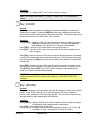
Item: STOP
Options:
0 through 7
Purpose:
A complete cycle of the MKIV Tag Injector consists of seven sequential steps called
“stops”. By changing the STOP number, the operator can select any one of the points in
the cycle as the place where the Injector will start and finish each time a tag is injected.
Figure 6: Stops of a MKIV Tag Injector cycle
Needle
Needle Carrier
Tag (red)
Cutter sleeve
Tag wire (blue)
Cutter pin
Stop 1: The needle/needle carrier
is back and tag is magnetized and
ready for insertion.
Stop 2: The needle/needle carrier
goes forward to a distance set by
NEEDLE MOVe (pg. 22)
Stop 3: The tag is pushed forward
to a distance set by SHOW (pg.
15).
Stop 4: The needle/needle carrier
is retracted.
Stop 5: The uncut tag wire (blue)
is retracted leaving the tag behind.
Stop 6: The cutter pin rotates up
or down as set by CUT EDGE
(pg.23). A new tag is cut.
Stop 7: Cutter pin rotates back
and the new tag is ready to be
moved forward by the tag wire.
Operation:
1) STOP [1] -- The needle begins at the “Stop 1” position shown in Figure 6. When
[TAG] is pressed, the needle moves forward into the specimen and the
tag is inserted.
2)
STOP [2] -- The needle begins at the “Stop 2” position shown in Figure 6. The
specimen has the needle inserted into it, [TAG] is pressed, the tag is
placed, and then the needle retracts out of the specimen. The length
of time that the needle stays retracted before returning to the extended
position is set using the MIN TIME option.
Note: When “STOP (2)” is used , MIN TIME (pg. 22) should also be adjusted.
MKIV Manual
CONFIGURATION
21
3)
STOP (0,3-7) -- are for diagnostic purposes and not recommended for tagging
specimens. "STOP (0)" puts the Injector in the continuous cycle
mode. In this mode once the Injector is cycled it will run
continuously until the [TAG] key is pressed again.
Item: NEEDLE MOVe
Options:
MAX, NO, S1 - S49
Purpose:
This item sets whether or not the Injector needle moves during the tagging cycle, MAX
or NO respectively, or to select a moving needle but with a reduced range of motion (S1S49).
Operation:
1) NEEDLE MOV(MAX) – The needle travels to its full extent. (See Figure 6, Stop 2
on pg. 21). Most common when using a head mold.
2) NEEDLE MOV(NO) – The needle does not move during the tagging cycle. Most
common when no head mold or jig is being used.
3) NEEDLE MOV(S1-S49) - Adjusts the amount of needle movement in 0.1mm
increments. For example, setting this option to S12 would
result in the needle moving forward about 1.2mm.
IMPORTANT: The SHOW value (pg. 15) must be changed when the NEEDLE MOVe is
changed.
Table 3: Common SHOW values
2.5" needles
3.5" needles
Needle Move SHOW
No
78
MAX
96
Needle Move
No
MAX
SHOW
171
193
Item: MIN. TIME
Options:
0 through 255
Purpose:
To allow the operator extra time to remove the specimen before the needle returns to the
extended position while using a STOP [2] item setting (pg. 21).
Operation:
This function introduces a delay into the injection cycle between Stop 1 and Stop 2
(Figure 6, pg 21). Each unit is equal to 0.01 second (10 msec).
22
CONFIGURATION
MKIV Manual
Item: QCD BEEP
Options:
0 through 5
Purpose:
To select the alarm tone for the Injector and QCD.
Item: QCD DELAY
Options:
20 through 150
Purpose:
To set the amount of time the QCD gate actuator or water jet solenoid remains on.
Operation:
Each unit is equal to one hundredth of a second (10 msec).
The value should be high enough to sort the largest specimen while at the same time
should be small enough to allow the water jets or mechanical gate to turn off/close
before the next specimen arrives at the separator.
Note: The QCD DELAY setting does not determine when the water jet comes on, only
the length of time it stays on after a tag is detected.
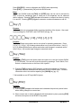
Item: CUT EDGE
Options:
1 through 4
Figure 7: Cutter edges
Cut Edge 2
Cut Edge 4
Index notch
Pin
Pin Rotation
Cut Edge 1
Sleeve
Index notch
(underneath)
MKIV Tag Injector Orientation
Needle
MKIV Manual
Cut Edge 3
CONFIGURATION
Wire Spool
23
Purpose:
This item sets which one of the four available edges on the cutter to use (Figure 7, see
also Figure 33). Use CUT EDGE to select a new cutting surface when the existing edge
becomes worn and will no longer make a clean cut of the tag wire. It is not necessary
to remove the cutter to change the cut edge. When changing between edges 1 or 2
and 3 or 4, the cutter must rotate 180 degrees. This rotation takes place during the next
injection cycle. When removing the cutter, the user should always note the position of
the index notch and replace it in the same orientation.
Item: TAG CREDIT
Options:
1 through 5
Purpose:
To set the number of Injector cycles allowed without a corresponding QCD cycle before
the missed tag alarm sounds.
Note: The TAG CREDIT setting does not change the QCD's detection and sorting
performance. Increasing the TAG CREDIT value simply allows the operator to
choose how many tags can be missed before the alarm sounds.
Operation:
The default TAG CREDIT is (2). Reasons to set the TAG CREDIT to a larger value are:
1) If you expect to have more than two specimens tagged before the first of those reach
the QCD.
2) If you prefer not to be alerted until more than a few tags have been missed.
Item: US-EURopean
Options:
0,000.0 or 0.000,0
Purpose:
This item sets the 1000 and decimal separator format according to the convention used
in the United States or Europe. For example, 1 million = 1,000,000 (US) = 1.000.000
(EUR). This item has no effect on the performance of the equipment.
24
CONFIGURATION
MKIV Manual
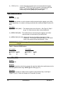
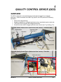
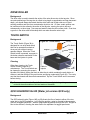
5
QUALITY CONTROL DEVICE (QCD)
OVERVIEW
The QCD is designed to automatically detect and separate tagged from untagged
specimens. When connected to the MKIV Tag Injector, the QCD performs the following
operations:
·
·
·
·
Detects the magnetized tag.
Separates tagged from untagged specimens using a mechanical gate or water jets.
The Injector counts tagged and untagged specimens.
Sounds the alarm when untagged specimens are diverted (see Tag Credit pg. 24).
Figure 8a: Quality Control Device (Mechanical Gate Version) – Electronics Box
side
Detection head
Gate actuator
(“Blue tube”)
Separator
Output
plate
Funnel
Input plate
Electronics box
Gate Box
Water supply hose
Interconnect Cable
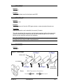
Figure 8b: Quality Control Device (Mechanical Gate Version) - Filter Side
Funnel
Funnel flow valve
Filter Housing
Quick Disconnect Fitting
Leg clamp
MKIV Manual
Water supply hose
quick disconnect
QUALITY CONTROL DEVICE (QCD)
25
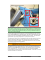
Water flows into the funnel to carry the specimen through the QCD detector head. Either
water jets or a mechanical gate in the separator are used to direct the specimen to either the
tagged or untagged outlet. When a tag is detected, the solenoid is activated and water flow
is directed to the opposite water jet or the gate actuator turns the gate-fin, directing the
specimen to the tagged outlet.
The QCD is designed to detect the presence of a magnetized tag in the specimen as it
passes through the detection head. Since untagged specimens will not create a magnetic
signal, the QCD cannot detect an untagged specimen. Instead, the QCD and Injector work
together to decide when an untagged specimen has passed through the QCD. This is done
by having each Injector cycle added to a memory buffer, and each tag detected by the QCD
subtracted from the same buffer. When the net buffer value limit, as set by TAG CREDIT
(pg. 24) is exceeded, it is assumed that a tag was missed and the alarm sounds.
The QCD is designed to detect extremely small changes in the magnetic field that are
caused when a tagged specimen passes through the detector head. To prevent false
signals, the QCD should not be subjected to unnecessary movement or jarred during
operation and should not be operated near sources of strong magnetic fields such as
motors, generators etc.
Tip: The effect of known sources of magnetic interference can be minimized by positioning
the QCD detection head perpendicular to the source of the interference.
ASSEMBLY
There are two different versions of QCD’s. One, the “Mechanical version”, uses a fin with an
actuator, (Figures 8a and 8b). The other QCD, the “Water jet” version, uses water jets with
a solenoid, to divert tagged specimens in the separator (Figures 15a and 15b).
General Assembly (Mechanical and Water Jet Versions)
To assemble the QCD, position the unit upside down (open side of the cover facing up) on
the floor or other flat surface. There are two different styles of legs used on the QCD.
QCD's manufactured before March, 1990 use a system where wing screws are tightened
through the leg brackets against the QCD frame. QCD's manufactured since March, 1990
use a quick release system which compresses a collar and plastic sleeve around the QCD
frame.
Collar and sleeve style legs. Loosen the leg clamps (Figure 8b) by turning the small black
lever-style handle located at the rotating joint between the legs and the frame of the QCD.
Space is limited so the handles cannot always make a full turn. To help in this situation the
handles have built-in clutches. Pull the handle out for free turning, allow the spring to pull it
back in and it will operate the clamp. Unfold the short legs and position them so they are
about 2 mm (1/16 in) from the output plate (Figure 8b) of the QCD. Unfold the long legs and
position them so they are approximately 2 mm (1/16 in) from the input plate of the QCD.
Tighten the leg clamps to hold the legs in place. Turn the QCD upright and stand it on a
level surface.
Attach the QCD funnel to the corresponding connectors at the input end of the QCD (Figure
9). One of the two female quick disconnect fittings is loose in the input plate to make
alignment of the funnel easier. Secure the funnel’s fittings in place with the retainer clips.
The top edge of the funnel should be approximately level. Adjust the legs if necessary.
26
QUALITY CONTROL DEVICE (QCD)
MKIV Manual
Figure 9: QCD Quick Disconnects
Funnel
O-ring
Funnel Fitting
Retainer Clip
Quick Disconnect Fitting
(open position shown)
Tip: Many of the plumbing connections on the QCD use quick disconnect fittings which are
held in place by a sliding retainer clip (Figure 9). Sliding the retainer in one direction allows
the fitting to be taken apart and sliding the retainer in the opposite direction locks the fittings
together. The fittings will go together more easily if the "O" ring is lubricated with water or
another lubricant before assembly.
Locate the water supply hose quick disconnect. Screw the threaded end of the connector
onto a standard garden hose or other water supply. The other end has a sliding collar which
connects to the QCD Filter Assembly (Figure 8b and Figure 39, pg 44). The water supply
should provide a flow of about 2 gal/minute (7.5 L/min) at 40 psi (3 kg/cm).
The Interconnect Cable is 10 feet (3 m) long and has the same style connector at each end.
Attach the Interconnect Cable from the QCD electronics box to either of the two large
connectors on the back of the Injector. The two large connectors at the rear of the Injector
are identical and may be used interchangeably.
WARNING! DO NOT attach the QCD while the Injector is turned on to avoid
DAMAGING the internal electrical components!
Although the QCD comes equipped with a filter, it is a fine mesh and will quickly become
clogged if the water supply contains much debris. We recommend that you filter the water
before it reaches the QCD. This can be done with any of the commercially available
products designed for larger volumes of water and easy cleaning. Contact NMT if you need
assistance selecting one of these filters.
MKIV Manual
QUALITY CONTROL DEVICE (QCD)
27
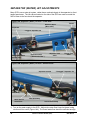
Mechanical Diverter Gate Assembly
Figure 10: Mechanical Gate Parts
Heat Sink
Actuator
Actuator mount
Coupler
Toe Clamp Bolt
Toe Clamp
Fin
Bumper mount
Stop pin
Bumper
Fin Pin
1) With the Toe Clamp bolts loose, rotate the fin over to one side or the other as far as it
will go. Tip the long end of the fin down and put it into the separator section first. Slide
the Toe clamp over the separator and line-up the Fin pin on the diverter assembly with
the Fin bearing of the separator (Figure 11).
Figure 11
Large side of the toe
clamps face inwards
Separator
Locate the fin pin in
the lower fin bearing
of the separator
Slide the small side
of the toe clamp over
the separators lip
2) Rotate the other toe-clamp end into position. The diverter assembly should now have
both of the toe-clamps over the plastic, and the mount under the plastic. Ensure that the
“small” end of the toe clamp goes all the way over the separator’s lip. Tighten one side’s
toe clamp bolt a little followed by the opposite side’s toe clamp bolt a little. Keep
repeating until the diverter gate assembly feels secure (Figure 12).
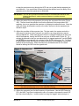
3) Make sure the fin moves freely (Figure 13A). If the fin is not moving freely then readjust
the position of the diverter assembly. Set the right hand bumper stop so that the fin tip is
flush with the Fin Shields (Figure 13B and C). Hold the Fin in position while tightening
the bumper. This will be the at rest position (no tag present). Move the Fin to the other
28
QUALITY CONTROL DEVICE (QCD)
MKIV Manual
(tag present) side and adjust the left bumper so the Fin’s tip is flush with its respective
Fin Shield (Figure 13D).
Figure 12
Large end of
toe clamp
Small end of
toe clamp
Fin bearing of
the separator
Toe clamp bolts
Separator Lip
Figure 13
A
Right Bumper
B
D
C
Hold Fin here
while adjusting
Fin Shields
Left Bumper
adjustment
bolt
4) Plug the actuator into the QCD’s Gate Box (Figure 1b, pg. 5). Plug the power supply to
the Gate Box (NOTE: it must be a 24VDC power supply). Plug the Gate Box to the
QCD Electronics Box and the MKIV Tag Injector. To test that the QCD Diverter gate and
the Fin are properly adjusted, turn on the Injector, press [SHOW], and then press [STEP]
several times (see pg. 15).
MKIV Manual
QUALITY CONTROL DEVICE (QCD)
29
SEPARATOR (WATER) JET ADJUSTMENTS
Many QCD’s use a water jet system, rather than a mechanical gate in the separator to divert
tagged specimens. The two valves located on the side of the QCD are used to control the
flow of water to the funnel and the separator.
Figure 14A: Separator (Water) Jet QCD – Valve Side
Funnel
Detection Head
(“Blue tube”)
Separator
“Tagged” Separator Jet
Interconnect Cable
attaches here
Electronics box
(“Electronics Box”)
Separator Flow
Valve
Funnel Flow
Valve
Figure 14B: Separator (Water) Jet QCD - Solenoid side
Separator Jet Nut
“Untagged” Separator Jet
Valve Body
Water Source
enters here
Filter Assembly
Solenoid Assembly
1) Turn on the water supply to the QCD. Adjust the water flow from the funnel using
the funnel flow valve (Figure 14A). The funnel water flow should be sufficient enough
30
QUALITY CONTROL DEVICE (QCD)
MKIV Manual
to keep the specimen moving through the QCD, but not so great that the separator jets
are ineffective. If too much water is flowing through the detector head, the ability of the
separator jets to direct the specimens is diminished.
IMPORTANT: The flow and jet position settings should be checked when specimen size
changes significantly, water pressure changes, or sorting accuracy
decreases.
2) Adjust the water flow to the separator jets using the separator flow valve (Figure
14A). The flow should be sufficient to move the specimen to the proper side of the
separator, but not so great that the specimen is subjected to excessive forces. Since the
water will always be diverted to one jet or the other, the flow to the two separator jets
should be equal.
3) Adjust the position of the separator jets. The jets used in the system work with a
wide range of specimen sizes; however, very small or very large specimens require
some jet adjustment. Water normally flows from the “untagged” separator jet down one
side of the separator, leaving the QCD from only one of the two exits (Figure 15). To
activate the solenoid so that you can adjust the jet for tagged specimens, use the [TAG]
and [STEP] keys as explained in the section for the SHOW function (pg. 15). To adjust
the jet position, loosen the knurled nuts which hold the jet in the separator housing and
position the jets as desired. When the solenoid is activated almost all of the water
should be leaving the QCD from the opposite exit.
Figure 15: Separator Jets
Separator Jet Nut
“Untagged”
Separator Jet
“Tagged”
Separator Jet
Almost all of the
water should flow out
this exit when the
solenoid activates
(QCD detects a tag).
Solenoid
Untagged
Specimen
Exit
Tagged
Specimen
Exit
Warning: The separator jets’ nuts should be only finger-tight. Over-tightening may cause
the whole jet assembly to turn in the separator housing.
4) Adjust the separator jets for the frequency of specimens. Use the QCD Delay (pg.
23) in the MKIV Tag Injector’s adjustment menu to increase or decrease the amount of
time the solenoid stays on. In other words, how long the “tagged” water jet stays on.
MKIV Manual
QUALITY CONTROL DEVICE (QCD)
31
6
MAINTENANCE
This chapter describes how to completely disassemble the outer parts, reassemble the outer
parts, and how to inspect key parts of the MKIV Tag Injector.
The frequency with which various components of the MKIV Tag Injector require
maintenance depends on a variety of factors such as water environment (fresh vs. salt),
species being tagged and quantity being tagged. Some components, especially the cutter,
require daily maintenance during tagging. The frequency of maintenance for other
components is more dependent on the species and/or target area for the tag. For example,
the harder the target location for the tag, the quicker the needle will become dull, and the
more frequently it will need to be sharpened. It is recommended that one fully service their
Injector prior to storage to ensure it is ready for the next tagging session.
INJECTOR DISASSEMBLY
1) Remove any tag wire from the Injector.
2) Remove the head mold (or needle support tube), the cutter, the brass needle nut and the
needle. Loosen the needle carrier clamp screw (Fig. 16) and remove the needle carrier
using the 6-32 x ¾ inch socket head cap screw found in the MKIV tool kit (pg. 49).
Figure 16
Needle Carrier
Needle Carrier
Clamp Screw
6-32 x ¾ inch
cap screw
Needle Carrier Clamp
3) Disengage the drive roller latch and remove the idler roller arm followed by the drive
roller. If the drive roller is seized to its shaft use the drive roller puller found in the MKIV
tool kit (Figure 17).
Figure 17
Latch
(disengaged)
Drive Roller Puller
Drive Roller
Idler Roller Arm
MKIV Manual
MAINTENANCE
33
4) Loosen the entry wire guide’s set-screw and remove the wire guide (Figure 18).
Figure 18
set screw
Entry wire guide
Wire guide holder
5) Loosen the set screws in the offset arm and remove the actuator arm using the modified
.050” hex wrench in the tool kit (Figure 19).
Figure 19
Offset arm
Actuator arm
set screw
6) Loosen the set-screw and remove the cutter block wire guide (Figure 20).
Figure 20
Cutter Block
Screw Driver
Handle
1/16 in. hex wrench
set screw
Cutter block
wire guide
7/64 in. Hex wrench shaft
pliers
Tip: If the wire guide is stuck, remove the 7/64 inch hex wrench shaft from its handle, butt
the hex wrench shaft up to the wire guide inside the cutter block, and use the handle of
a screw driver to GENTLY tap the wire guide free (Figure 20).
34
MAINTENANCE
MKIV Manual
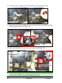
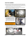
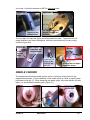
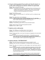
INJECTOR ASSEMBLY
This section assumes that you have already completely disassembled and cleaned (see pg
45) the outside components of a MKIV Tag Injector and are now ready to reassemble them.
1. Insert cutter pin and sleeve. Hold the cutter towards the Injector, compressing the spring
while tightening the screws using a 7/64 inch hex wrench (Figure 21).
2. Lightly lubricate the motor shafts (Figure 21) with silicone based grease and attach the
Actuator Arm assembly but do NOT tighten yet (Figure 22).
Figure 21
Figure 22
motor shafts
Actuator Arm
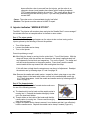
3. Insert the needle carrier so that the back
lip of the needle carrier is flush with the
rear of the needle carrier clamp. Using a
3/32 inch hex driver, tighten the needle
carrier clamp just enough so as the needle
carrier will not slip in the clamp (Figure
23).
WARNING: DO NOT over tighten the
needle carrier clamp. Doing so may cause
irreparable damage to the needle carrier
clamp AND/OR the needle carrier!
Figure 23
Needle Carrier Clamp
3/32 inch
hex wrench
Needle Carrier
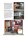
4. Slide the cutter block wire guide into its hole until it touches the cutter. Slide the entry
wire guide into its mounting block until the lip of the wire guide is flush with the front of
the holder and tighten their set screws (Figure 24).
Figure 24
1/16 inch hex wrench
set screws
Push cutter block wire guide
all the way into its hole until
it touches the cutter
MKIV Manual
MAINTENANCE
Entry wire-guide lip
should be flush with
its mounting block
35
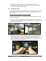
5. Slip the drive roller onto its motor shaft
but do NOT tighten its set-screws yet.
Fasten the idler roller arm. As you
compress the spring while positioning
idler roller arm and shoulder bolt, turn
the latch to the disengaged position
(down). Turning the latch down will not
only help in lining up the shoulder bolt,
but will also give added protection from
the spring slamming the idler roller into
the wire-guides (Figure 25).
Figure 25
Drive roller
1/8 inch
hex wrench
Spring
Shoulder bolt
6. Engage and line up the drive roller with
the idler roller. Tighten the set-screws
(Figure 26). Disengage the drive rollers.
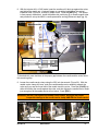
7. Turn the Injector on and enter LOAD
mode by pressing the [LOAD] key on
the top of the Injector. Push on the front
side of the needle carrier until it is up
against the inside of the head mold
holder/magnetizer (Fig. 27). Use the
modified 0.050 inch L-shaped hex
wrench from the MKIV toolkit and tighten
the setscrews of the actuator arm
assembly (Fig. 27).
Idler roller arm
Figure 26
1/16 inch hex
wrench;
older models
use a 0.050 inch
hex wrench.
Figure 27
set screws
.050" Hex
wrench
(modified)
Push
needle
carrier
Head mold holder/
magnetizer
36
MAINTENANCE
MKIV Manual
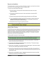
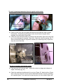
8. With the Injector still in LOAD mode, insert the needle until it butts up against the cutter,
and tighten the needle nut. A piece of paper or something bright below the vertical
inspection hole (Figure 28, 29 and 32) helps to see. Press the [ESC] key. The Injector
is now properly assembled. Install the head mold, positioning jig or needle support tube
and proceed to set up the MKIV’s needle penetration and tag placement depth (pg 10).
Figure 28
Needle carrier
Needle
Cutter
Vertical inspection hole
Needle nut driver
To be absolutely sure that there is the proper gap between the needle and the cutter follow
this remaining step.
9. Loosen the needle carrier clamp using the 3/32 inch hex wrench (Figure 29). With the
needle carrier clamp still loose, push the needle/needle carrier assembly towards the
cutter until you see the funnel end of the needle touch the cutter. Press the [LOAD] key,
while still holding the needle against the cutter, and then tighten the needle carrier clamp
just enough so as the needle carrier will not move. Press [ESC].
WARNING: DO NOT over tighten the needle carrier clamp. Doing so may cause
irreparable damage to the needle carrier clamp AND/OR the needle carrier!
Figure 29
Needle carrier clamp
MKIV Manual
3/32 inch Hex driver
MAINTENANCE
37
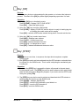
PARTS INSPECTION
NEEDLE
Background
The needle should be kept clean and sharp. A dirty needle may cause tag jamming,
improper tag placement, or pathogenic contamination. Clean the needle with detergent and
water, then rinse with alcohol. A sharp needle is required to repeatedly penetrate the fish
and deliver the tag to the target site.
The needle is held in the needle carrier by a compressed nylon ball slipped over the needle.
The ball and needle are retained by a brass clamping nut. The needle carrier is held by the
needle carrier clamp located between the cutter and the magnetizer (Figure 2).
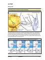
Needle Inspection, Reaming and Sharpening
Figure 30
Figure 31
When inspecting or replacing a needle, examine the slight "funnel" at the back end of the
needle with the magnifying loupe (Figure 30). The funnel helps guide the tag into the needle
and can be damaged if the tag wire jams in the Injector. The funnel can be reshaped using
the needle reamer and the sharpening stone in the tool kit. To reshape the funnel insert the
point of the reamer into the funnel and turn it a few times with light pressure to restore the
proper shape. The rim of the funnel must be smoothed with the sharpening stone to remove
the external flare caused by reaming. Inspect the needle to make certain it is straight. Bent
needles must be replaced.
Inspect the beveled end of the needle to see that it is smooth and sharp. A dull needle
makes penetration difficult and may tend to push the specimen away during tagging,
causing shallow implantation of the tag. The angle of the needle tip can be restored with the
sharpening stone and light oil (Figure 31). After sharpening the needle be sure to clean it
before reinstallation.
Tip: The needle carrier and needle can be removed as a unit for easier needle
maintenance. When removing the needle and needle carrier as a unit it is best to grab it by
the brass clamping nut so you don’t damage the needle carrier. The needle carrier is a very
expensive part compared to the clamping nut. Also be careful not to bend the needle.
When reinstalling the needle/needle carrier unit make sure the Injector is in LOAD.
38
MAINTENANCE
MKIV Manual
CUTTER
Background
Important! The cutter must be removed and cleaned at the end of each days tagging.
Avoid letting the pin and sleeve dry while assembled.
Cutter (motor) Block
Figure 32
Vertical Inspection Hole
Threaded holes used to
extract a stuck Cutter
Sleeve
Flange
Pin
Exit hole
of Cutter
Needle
Carrier
Bushing
Align the slot in the Cutter pin with
the drive pin on the Cutter motor
Alignment Pin
The cutter consists of an inner "pin", a "sleeve" and a "flange" (Figure 32). The tag wire
passes through holes in the sleeve and pin. Cutting is performed by rotating the pin within
the sleeve, thus shearing off the tag at the point where the wire enters the pin. Each cutter
has four cut edges (Figure 7, pg. 23 and Figure 33). The “cut edge” refers to the side of the
pin hole doing the work cutting the tag wire.
Figure 33: Cut edges shown from the inside of the MKIV injector looking out.
EDGE
EDGE
EDGE
1
2
3
Index notch
Entrance hole
Flange
EDGE
4
Sleeve
Pin
Tag (red)
MKIV Manual
Tag wire (blue)
MAINTENANCE
Needle
Needle Carrier
39
During normal operation, the cutter does not have to be removed to select a different cut
edge; however, a tag will not be cut on the newly selected edge until the Injector is cycled
once. A new cut edge can be selected using the CUT EDGE item (pg 23) in the
ADJustment menu ([ADJ]). Also, look at the CUT EDGE item setting when installing the
cutter to make sure the pin is in the correct orientation using the index notch as a reference
(Figure 33).
Tip: Record the cut edge change in the log book along with the Injector total (“INJ T”).
Keeping track of the number of cuts on a cut edge is useful in determining approximately
when the cut edge or cutter needs to be changed.
Keeping the cutter clean will result in the best performance, longest wear and avoids the
problem of a seized cutter. Never use tools to disassemble a stuck cutter. Using a
screwdriver, pliers or putting the cutter in a vise is almost certain to cause misalignment or
breakage. If the pin cannot be removed from the sleeve after the cutter is removed from the
Injector, put the cutter in an ultrasonic cleaner (most jewelers have these) with tri-sodium
phosphate (TSP) based detergent solution for one hour. This usually allows the pin to be
removed from the sleeve by hand. If you have any questions please contact NMT.
Cutter Inspection
Tag quality can be a key indicator of
Figure 34
the condition of a cutter or cut edge.
Badly worn or damaged cutters can
produce tags that are bent or with a
large tail (Figure 34). Damaged tags
may not pass through the needle,
causing the Injector to jam. If half
length tags are being cut then the
condition of the cut edge becomes
more critical. Using a worn cutter can
also damage the end of the tag
making subsequent reading difficult.
Occasionally inspect a tag with the
magnifying loupe, Magniviewer™, or
on a piece of tape (Figure 34) under a
microscope to determine that the tag ends are square.
Figure 35
Tag
Tail
Inspect the flange, cutter block surface, and cutter
holes for stray tags or wire (Figures 35 and 36a).
This can cause wire jams or make it hard to load
wire and possibly damage the cutter. The
sharpening stone (“Arkansas stone”) found in the
MKIV tool kit can be used to take down any high
spots from dents created by tags caught between
the flange and cutter block surfaces.
Check the outside surfaces of the flange and
sleeve. These two surfaces should be flush to
one another. Figure 36b shows a cutter’s flange
and sleeve whose outside surfaces are not flush.
Wire would either not load or load with difficultly
through this cutter. If you notice this problem with
40
MAINTENANCE
MKIV Manual
your cutter, it should be returned to NMT for attempted repair.
Figure 36a
Figure 36b
Tag wire in the
entrance hole
The flange and sleeve
outside surfaces are
not flush.
The cut edges of the pin and sleeve should be checked for wear. The pin has four cut
edges because it can rotate 180 degrees, while the cutter sleeve only has two cutting
surfaces (Figure 36c).
Figure 36c
Cutter pin
unused
edge
Unused
Used edge but
still functional
Used
These two cut
edges of this
cutter pin are
worn out
A look at the cut edges
inside the sleeve
NEEDLE CARRIER
The needle carrier holds the needle in place and is a critical part of the electronic tag
magnetization process. Correct installation of the needle carrier is critical to proper system
performance (see pg. 37). When inspecting the needle carrier, pay close attention for stray
tags in, on and around the needle carrier (Figure 37).
Figure 37 : Needle Carrier
Stray tag in
the threads
Stray Tags
MKIV Manual
MAINTENANCE
41
DRIVE ROLLER
Background
The drive roller is used to transfer the action of the wire drive motor to the tag wire. Since
accurate positioning of the tag wire is critical to tag length, magnetization and tag placement
depth, you should always be certain that the drive roller and its idler roller are in good
working condition and free from contamination by dirt or oils. Oil from certain species can
be transferred to the rollers by the action of the tag wire, causing the wire to slip and
subsequently cut short tags. Use soap and water to keep the drive rollers clean. Over time,
a groove in the drive roller will develop which can also cause the wire to slip.
TOUCH SWITCH
Background
The Touch Switch (Figure 38) is
designed for use as a hand switch
that can be operated hundreds of
times per hour without causing
operator fatigue. When the Touch
Switch button is pressed, a magnet in
the button closes a reed switch in the
base and the Injector is cycled.
Figure 38 : Touch Switch
Button
Pin Notch
Magnet
Spring
Block
Pin
Cleaning
Other than cleaning, the Touch
Cable to
Switch normally requires no
Injector
Screw
maintenance. The Touch Switch can
be cleaned by removing the screw in
the side of the block, tipping the block to allow the pin which restrains the push button to
slide out, and then lifting out the push button and spring underneath (Figure 38). The cavity
can then be cleaned and the switch reassembled. Dry the Touch Switch and its connector
before storing.
Tip: Some operators place the Touch Switch inside a small plastic bag during use to
minimize the accumulation of dirt and water on the switch.
QCD SOLENOID VALVE (Water jet version QCD only)
Background
The QCD solenoid valve (Figure 14B, pg 30) diverts the flow of water to either of the two
water jets in the QCD separator. In the inactive position, water is diverted to the separator
gate for untagged specimens. When a magnetized tag passes through the QCD, a signal is
sent to the solenoid, diverting the water flow to the separator for tagged specimens.
42
MAINTENANCE
MKIV Manual
Removal and Installation
The solenoid does not require any routine maintenance; however, you may have to remove
the solenoid if it becomes plugged by debris or otherwise fails.
To remove the solenoid follow these steps.
1) Note the position of the three water tubes and disconnect them at the quick
disconnect fittings.
2) Disconnect the electrical connector for the solenoid where it enters the QCD
electronics box.
3) Remove the wing screw which holds the solenoid bracket to the QCD frame.
4) If you are replacing the solenoid use the 9/64" hex wrench to remove the two cap
screws which hold it to the solenoid bracket. It is not necessary to remove the
solenoid from the bracket for normal servicing.
5) Reinstall the solenoid using the opposite procedure.
Important: When storing the QCD remove and drain the solenoid. If water freezes
inside the solenoid it may be damaged.
Solenoid Valve Cleaning
The QCD filter has been chosen so that anything that passes through the filter will also pass
through the solenoid. If the filter has been removed the solenoid can become blocked. The
solenoid can usually be cleaned by disconnecting it as explained above and removing the
debris from the water passages at the quick disconnect fittings. If the debris is inside the
solenoid then it will have to be disassembled.
To disassemble the solenoid, follow these steps:
Tip: Once disassembled, the two sides of the valve body (Figure 39a) are identical so
before disassembly, mark the side of the valve body into which the end cap fits.
1) Remove the plastic retaining cap and slip the housing, spring washer, coil and baseplate off the solenoid base sub-assembly.
2) Unscrew the solenoid base sub-assembly from the valve body. This requires a large
wrench which is not included in the tool kit.
3) Remove the core assembly, core spring and solenoid base gasket. Note that the rubber
end of the core assembly goes toward the valve body.
4) Unscrew the end cap and remove the disc holder spring disc holder sub-assembly and
end cap gasket. Note that the disc holder sub-assembly has three legs which only fit the
valve body one way.
5) All parts are now accessible to clean. Inspect the components and remove any debris.
Replacement solenoids are available from NMT.
MKIV Manual
MAINTENANCE
43
6) Reassemble in reverse order of disassembly (Figure 39a). The coil should be installed
so the larger end faces the base plate (Figure 14b, pg. 30). Lubricate the gaskets with
silicone grease. Torque the solenoid base sub-assembly and end cap to about 125 inch
pounds.
Figure 39a : QCD Solenoid Valve
QCD FILTER ASSEMBLY (Both QCD versions)
Background
The filter housing (Figure 39b and Figure 8a, pg 25) is between the water supply hose
adapter and the QCD valves. The filter housing contains a stainless steel 440 micron filter.
The filter is designed to prevent debris from clogging the solenoid valve.
Filter Cleaning
Two methods are available for cleaning the filter. The easiest and fastest is by back flushing
with water. To back flush the filter remove the water supply hose from the filter assembly
and disconnect the filter assembly from the valve body. Flow water through the filter in the
44
MAINTENANCE
MKIV Manual
direction opposite to the normal flow (so water flows opposite the direction of the arrows on
the filter assembly). This will usually force most of the loose debris out of the filter.
Figure 39b : QCD Filter Assembly
Filter Housing
Filter
Filter
Gasket
Gasket
Filter Housing
If the filter must be removed for cleaning or replacement follow these steps.
1)
2)
Remove the filter assembly from the QCD.
With a large wrench unscrew the housing which contains the filter (Figure 39b).
The filter can now be removed for cleaning or replacement. Be careful not to
loose the gasket.
Before reinserting the filter inspect the gasket which seals the filter housing. The factory
supplied gasket is metal and will eventually wear out. If the gasket is worn it will be evident
by water leaking from the small hole in the side of the filter housing. Non-metal replacement
gaskets are available from NMT.
Note: The replacement (non-metal) gasket is recommended for salt water use.
CLEANING PROTOCOL
The possibility of spreading fish diseases between culture facilities and watersheds is of
concern to both our customers and Northwest Marine Technology. Although we are
unaware of a case of coded wire tagging equipment, moved between locations, as having
served as a vector in spreading a disease, the potential consequences of such occurrences
call for stringent preventative measures. Disinfection procedures should also be
implemented between groups of fish, within a facility, when signs of disease exist. Tagging
should not be conducted during a severe outbreak of disease.
Chlorine solutions are recommended as disinfectants on tagging equipment. Commonly
used sources of chlorine are calcium hypochlorite ("HTH") and solutions of sodium
MKIV Manual
MAINTENANCE
45
hypochlorite ("bleach"). Household bleach comes in a concentration of about 5% so that to
achieve the desired concentration one would dilute to a ratio of 1:250 (1 oz of bleach per 2
gallons water). Stronger solutions may be available at fish rearing facilities so that a lesser
proportion of material would be required to achieve the desired concentration (200 ppm) of
active ingredient. To reduce corrosion, alcohol (70 - 90%) is recommended as the
disinfectant and cleaning agent for the interior mechanisms of the MKIV and other NMT
equipment.
Calcium hypochlorite and sodium hypochlorite solutions are highly toxic to fish but can be
neutralized by adding sodium thiosulfate or sodium sulfite to the solution. As a "rule of
thumb", if a five percent solution of these chlorine compounds is used as a disinfectant,
they can be neutralized by adding an equal weight of either chemical. For example, 1 ounce
(29.6 mL) of 5% bleach added to 2 gallons (7.57 L) of water would be neutralized by 1
ounce (28.4 g) dry weight of either sodium sulfite or sodium thiosulfate. If the chlorine
solution is stronger, the weight of the neutralizing agent should proportionately increase. As
an added precaution, "neutralized" disinfectant should not be poured directly into water
containing fish.
Important: Before the use of any disinfectant, read and understand the Material Safety
Data Sheets (MSDS) for each product.
Equipment and Supplies
In addition to the disinfectants indicated above, the following equipment and supplies are
recommended:
·
·
·
·
·
·
·
·
·
·
·
·
·
·
·
·
·
Two spray bottles for dispensing alcohol and chlorine solutions
Tap (pathogen free) water
50 ml syringe with 20 gauge needle
Wiping sponge/cloth
Cotton tipped applicators made of wood (available from medical supply stores)
Cotton balls
A 2 - 3 inch length of blank/excess coded wire
DCWT tool kit
MKIV Tag Injector instruction manual (this manual)
Paper towels
An open container for soaking parts
A pump and appropriate fittings for circulating disinfectant through a QCD
A large open container for holding and catching disinfectant pumped through a QCD
Material Safety Data Sheets
Rubber gloves
Eye protection
Particle masks or respirator
Injector
Using tap water and sponge, wipe down the exterior surfaces of the Injector taking care to
remove extraneous material. Repeat this procedure with the touch switch, power supply
and attendant cords. Following this, choose a well ventilated work location free from
hazards that could ignite alcohol. Place the Injector on a clean surface that has been
disinfected with the chlorine solution. Secure the MKIV Tag Injector’s electrical outlet caps
46
MAINTENANCE
MKIV Manual
and wipe all the exterior surfaces with the chlorine solution. Without wetting the electrical
connections with the disinfectant, thoroughly wipe the touch switch, power supply and
attendant cords.
Remove the head mold and clean with the chlorine disinfectant. DO NOT USE alcohol on
the head molds because it may damage the surface material. Open the Injector and remove
the tagging needle, needle carrier, clamping nut, and dismantled cutter. Immerse these
parts into a container of chlorine disinfectant. Remove the screws that hold the head mold
(positioning jig) and immerse them in the same solution. Immerse tools, and other contents
of the kit including the case, in the disinfectant. Remove the idler roller arm and the rear
wire guide. There is an E clip holding the needle arm on the drive cam. Remove it and the
needle arm. Spray the alcohol solution onto the exposed interior surfaces (including the
case) taking care to include drive rollers, wire guides, tension spring, drive roller latch (in
both up and down positions), hinges, lower drive roller arm, and all screws. With alcohol
wetted cotton tipped applicators, thoroughly clean all surfaces and orifices/tubes of the
head mold holder, needle carrier, needle carrier clamp, vertical inspection hole, cutter motor
drive pin, cutter motor block including hole for cutter pin, and alignment pin. Shift the
moving parts to and fro during the process to insure that all surfaces are exposed to the
cleansing agent. Remove the caps from the electrical outlets and spray with the alcohol
solution allowing evaporation to occur prior to replacing the caps. Similarly spray the
electrical connections of the power supply and touch switch.
Rinse the soaking Injector parts, tools and case in tap water. Remove any debris adhering
to the cutter parts. Using a length of tagging wire dipped in alcohol, probe the holes in the
cutter sleeve and cutter pin to clear them of any material. Insert the tagging needle into the
20 gauge barrel of an alcohol-loaded syringe and force a stream through the tagging needle.
After removing the hypodermic needle from the loaded syringe, force alcohol through the
needle carrier. Remove the soaking parts and tools, spray with alcohol, and reassemble the
parts using disinfected tools. After replacing the 20 gauge hypodermic needle onto the
loaded syringe, fit it over the refitted tagging needle and force alcohol through the needle,
toward the interior of the Injector, until a steady stream reaches through to the drive rollers.
Using the same syringe, insert it into the wire guide leading to the drive rollers, and force
alcohol through until a steady stream reaches the drive rollers. Allow the equipment to dry
in sunlight if possible.
Quality Control Device (QCD)
Attach the QCD to the MKIV Injector, power source, and tap water, allowing the water to run
through the device for several minutes. During this period, divert the flow through both
water jets by activating the solenoid valve by pressing [STEP] on the control panel of the
MKIV. Using tap water and sponge, wipe down the exterior surfaces of the QCD taking care
to remove extraneous material. Following this, choose a well ventilated work location.
Place the QCD on a clean surface that has been disinfected with a chlorine solution or other
suitable disinfectant.
With the QCD attached to the MKIV and power, spray and wipe down the exposed surfaces
of the QCD with a chlorine solution including all surfaces of the legs. Remove the cover and
repeat the process on the exposed surfaces, including inside the cover, taking care to reach
all of the nooks and crannies. The most practical, and recommended, procedure that
follows requires the use of a pump to recirculate chlorine solution through the QCD.
Prepare enough solution to operate the pump and place the container in a position to catch
the solution exiting the discharged ports as it is pumped/recirculated through the machine.
MKIV Manual
MAINTENANCE
47
Allow this to occur for several minutes while diverting the flow through both water jets by
again activating the solenoid valve.
After letting the equipment stand for 15 minutes, rinse the surfaces with tap water and then
run tap water through the QCD while again activating the solenoid valve. Allow the QCD,
with cover removed, to dry in sunlight if possible.
Other disinfection protocols
Care must also be taken to disinfect nets, buckets, hoses, boots, rain gear and any other
equipment that has come in contact with fish or fish-bearing water that could serve as a
vector for diseases.
Procedures Involving Tagging Trailers
Large scale coded wire tagging operations may involve mobile trailers each housing several
tagging units. Disinfection of equipment in these trailers is very similar to the previously
described procedures, but in most cases domestic water will not be readily available.
Carefully remove extraneous material from the trailer and equipment using a wash down
hose and sponge. Wear protective clothing, and conform to other safety precautions,
recommended in the MSDS and open all doors and windows. Into a measured amount of
water in a large container, such as holding tank or tote, add an amount of chlorine
disinfectant required to achieve the desired concentration. Immerse the main trailer water
pump into the container.
The next procedures follow those already described in previous sections, with the wash
down hose used to apply the disinfectant to chlorine disinfectant. Disinfectant must be
applied to all surfaces that have, or may have, come in contact with fish or hatchery water.
In this case, since tap water is unavailable, the disinfectant is not rinsed from the tagging
equipment until the trailer arrives at its next tagging station.
Further details about disinfecting tagging trailers are available from individual agencies and
in the users manual for the AutoFish System.
48
MAINTENANCE
MKIV Manual
7
APPENDICES
APPENDIX A: Tool Kit Components
Figure 40a: Tool Kit
4
7
3
1
9
2
5
6
10
8
11
12
13
14
15
16
17
18
19
20
Tool Kit components and their identifying names are shown below. Since the contents are
modified from time to time the exact appearance of the components may vary slightly.
1.
2.
3.
4.
5.
6.
7.
Needle reamer (pin vise)
Needle reamer bit
Spare screws and clips
Shaver brushes
Sharpening stone
5X Magnifying loupe
6-32 x ¾ inch screw for removing
needle carrier
8. Drive roller puller
9. Needle protector
10. Needle support tube
MKIV Manual
11. Head mold base
12. Hemostat
13. Forceps
14. 1/8 inch Hex driver
15. 7/64 inch hex driver
16. 3/32 inch hex driver
17. 1/16 inch hex driver
18. 1/8 inch nut driver
19. 0.050 inch hex wrench (modified)
20. Hard wire cutters
APPENDIX A: Tool Kit Components
49
APPENDIX B: Main-plate Parts List
20
1
2
11
17
17
7
6a
4
19
8
3
5
9
6b
10
10
12
18
17
15
13
13
16
14
Figure 40b: Injector Main-plate
This is a list of replaceable parts located on the main-plate of a MKIV Injector. The name of
the part is listed followed by the NMT part number in italics. Not shown are the various
needles or head molds.
1. Needle carrier (with nut) - NEE000009
2. Needle carrier clamp – NEE000008
3. Cutter – CUT000002
4. Cutter block wire guide – WIR020740
5. Actuator arm – NEE010661
6. Drive roller set – DRI000002
7. Offset arm – NEE010680
8. Entry wire guide – WIR020760
9. Pin bushing – NEE010740
10. Small e-clip (2 places) – RET014260
11. Spool retainer – SPO017180
12. Drive roller latch – PRE011980
50
13. Shoulder bolt (2 places) – SCR015780
14. Large e-clip – RET014280
15. Idler roller arm – PRE012000
16. Pressure spring – SPR017240
17. 6-32 Ag tip set screw (6 places) –
SET016640
18. Head mold base – HEA007420
19. 4-40 Ag tip set screw (2 places) –
SET016620
20. 6-32 x 3/8 SS cap screw (2 places) –
SCR015140
APPENDIX B: Main-plate Parts List
MKIV Manual
APPENDIX C: Adjustment Menu
ITEM
OPTIONS
REMARKS
SETUP
See Appendix C
Sets certain parameters to pre-defined
values
TAG LENgth
HALF, SINGLE, 1 1/2, DOUBLE Selects tag length
WIRE
NORMAL, EZ-FIND, NON-STD,
MAG OFF
Magnetizer Control
QCD
THRESHold
0 through 255
Detection sensitivity. Smaller value is
more sensitive
STOP
0 through 7
0 is free run. 1 though 7 select other
stops in the Injector cycle
NEEDLE
MOVe
MAX, NO, S1,...,S49
Activates, deactivates or mini-steps the
needle move
MIN. TIME
0 through 255
Injector cycle time in hundredths of a
second
QCD BEEP
0 through 5
Selects alarm tone
QCD DELAY
20 through 150
Solenoid valve “on” time in hundredths of
a second
CUT EDGE
1 through 4
Selects cutter edge
TAG CREDIT
1 through 5
Number of Injector cycles remembered
against QCD activations
US-EUR
0,000.0 or 0.000,0
US or European punctuation
MKIV Manual
APPENDIX C: Adjustment Menu
51
APPENDIX D: Setups
Setup Name
Tag
Length
Wire
QCD
Stop
Thresh
Needle Min.
Move Time
STANDARD
Single
Normal
50
1
Yes
0
Most tagging
1½
1½
Normal
50
1
Yes
0
Large specimen,
easier to detect
DOUBLE
Double
Normal
50
1
Yes
0
Large specimen,
easier to detect
CUSTOM 1
Single
Normal
50
1
Yes
0
Special operator
setup1
CUSTOM 2
Single
Normal
50
1
Yes
0
Special operator
setup1
SPECIAL
X
X
X
X
X
X
See note below2
HALF EZ
Half
EZ-Find
50
1
Yes
0
not used
HALF
Half
Normal
20
1
Yes
0
Small specimen
Typical Use
1. As delivered, the Injector will have the values shown above for CUSTOM 1 and
CUSTOM 2. The operator may change these values as described in the section
covering adjustments (pg.19).
2. Any set of adjustment values which does not correspond to the currently active setup
(either pre-defined or custom) will show as SPECIAL. This alerts you that non-standard
values are active so that unintentional changes do not take place.
52
APPENDIX D: Setups
MKIV Manual
APPENDIX E: Size conversion table for salmonids
Size conversion table for salmonids based upon measurements of Chinook salmon.
Numbers
per
pound
1200
1100
1000
800
700
600
550
500
475
425
400
380
360
340
320
300
290
280
270
260
250
240
230
220
210
Grams
per fish
Fork Lengths
Inches
Centimeters
0.33
1.32
Conversion not available
0.45
1.40
0.57
1.52
0.65
1.58
0.76
1.67
0.82
1.71
0.91
1.77
0.96
1.80
1.07
1.87
1.14
1.91
1.19
1.94
1.26
1.97
1.35
2.02
1.48
2.08
1.52
2.10
1.57
2.13
1.62
2.15
1.68
2.17
1.75
2.20
1.82
2.23
1.89
2.26
1.98
2.28
2.07
2.32
2.16
2.36
3.35
3.56
3.86
4.01
4.24
4.34
4.50
4.57
4.75
4.85
4.92
5.00
5.13
5.28
5.33
5.41
5.46
5.51
5.58
5.66
5.74
5.81
5.94
6.00
Numbers
per
pound
200
190
180
170
160
150
140
130
120
110
100
90
80
70
65
60
50
45
40
30
20
15
10
9
5
Grams
per
fish
Fork Lengths
Inches
Centimeters
2.27
2.40
6.10
2.39
2.44
6.20
2.52
2.49
6.30
2.69
2.53
6.40
2.84
2.59
6.60
3.03
2.64
6.70
3.24
2.69
6.83
3.49
2.80
7.08
3.78
2.85
7.20
4.13
2.95
7.45
4.54
3.03
7.70
5.04
3.13
7.95
5.67
3.26
8.30
6.48
3.41
8.66
Conversion not available
7.56
3.56
9.10
9.08
3.81
9.70
Conversion not available
11.54
4.13
10.50
15.12
4.51
11.46
22.68
5.17
13.13
Conversion not available
45.36
6.52
16.56
50.00
6.73
17.10
Conversion not available
NMT stock coho\Chinook head mold sizes are highlighted in yellow.
MKIV Manual
APPENDIX E: Size conversion table for salmonids
53
APPENDIX F: System Messages
The system will display different messages to confirm its operating status. These messages
and their meaning are explained below.
BAD DRIVE XY: Indicates an internal failure of the motor or motor drive circuitry. When
Y=0 the Wire motor has failed, Y=1 the Needle motor has failed and Y=2 the Cutter motor
has failed. The Injector must be returned to NMT for servicing.
BAD MEMORY: The system has a memory which retains menu settings and cycle counts
even with the power off. If this memory fails or resets the Injector will display “BAD
MEMORY”. Press the [*]key to clear this message which will prompt the “CHECK ALL ADJ”
message. If the message cannot be cleared, the Injector must be returned to NMT for
servicing.
CHECK ALL ADJ: The stored settings have been lost and all values have reverted to the
standard factory settings. All adjustments should be checked and reset if necessary.
CHECK NEXT TAG: If the wire does not succeed in extending to its proper position, the
Injector will complete its cycle, then stall and display this message. (pg. 56)
CUTTER STUCK: The cutter is unable to complete its cycle. (pg. 57)
INT ERROR: Indicates an internal failure. (pg. 55)
NEEDLE STUCK: The needle actuator (drive) arm is unable to extend or return all the way.
(pg. 58)
NO QCD OK: This message appears if the Injector is turned on and a QCD is not attached.
Pressing [OK] to continue if there is no QCD attached.
NO WIRE OR STUCK: At the end of each cycle, the Injector cuts and magnetizes a tag for
injection during the next cycle, and verifies that a magnetized tag is actually present in the
needle. This test is skipped if the WIRE menu item is set to “(MAG OFF)”. (pg. 55)
POWER LOW: This message appears if the power supply voltage to the Injector drops
below about 11.5 volts. When the power supply voltage is low the Injector will run slower
than normal. You can display the actual voltage by pressing the [BATT] key. (pg. 62)
READY VX.X: The power-on message identifies the firmware version “X.X” installed on the
Injector. This message also indicates that the equipment has passed the power on self-test.
On a MKIVb this message will say “MK4B V X.X”.
*RELOAD WIRE: MK4b V X.X only. The Injector has lost the position of the wire due to an
improper shutdown. (pg. Error! Bookmark not defined.)Error! Reference source not
found.Error! Reference source not found.
WEAK MEMORY: After many years this memory will begin to wear out and will give the
warning WEAK MEMORY. After this message is displayed you can safely finish out the
tagging season but should return the equipment to NMT at the earliest convenient time.
54
APPENDIX F: System Messages
MKIV Manual
APPENDIX G: Troubleshooting
1. Injector displays “NO WIRE OR STUCK”.
Cause: Tag wire has run out or the drive rollers are not engaged.
Solution: Install a new spool of tag wire. Make sure the drive rollers are in operating
position.
Cause: The needle carrier is improperly installed.
Solution: Make sure the needle and needle carrier are properly installed. Refer to pg.
37 step 8 in the Maintenance chapter.
Cause: The drive roller is loose or not making firm contact with the wire.
Solution: Confirm that the drive roller is secure to the motor shaft. Confirm that the
idler roller can rotate freely. Confirm that the wire guides are NOT making
contact with the drive rollers. Inspect both the idler and drive roller for
grooves. Sometimes the drive roller can be adjusted on its motor shaft to
avoid any grooves in its tread.
Cause: [OK] was used to exit LOAD mode but the wire was not at the tip of the needle
causing the wire to be retracted too far.
Solution: Return to LOAD mode, turn the drive rollers clockwise by hand to advance
the wire to the tip of the needle and press [OK].
Cause: [SHOW] is not set properly. Too small of a SHOW value may cause cut tags
not to be expelled from the needle and to build up or may cause the tag wire to
be retracted too far and not be cut at all. Too large of a SHOW value causes
the wire to be extended too far and not cut because the Injector cannot find the
end of the wire.
Solution: Adjust [SHOW] so that the cut tags are pushed to the end of the needle and
are expelled each machine cycle (pg. 15).
Cause: The Injector’s magnetizer and/or associated detector electronics may not be
operating properly.
Solution: Return Injector to NMT for repair.
2. Injector displays “INT ERROR”.
Cause: The Injector has lost track of its motor position.
Solution: Turn the Injector off and remove any wire still loaded. Turn on the Injector.
Press the [OK] key if the display says “No QCD OK?”. Next press the
[LOAD] key followed by the [OK] key ([ESC] will not work). The Injector
should now be ready to load wire and resume tagging.
Cause: The Injector’s internal circuitry has suffered an unrecoverable failure.
Solution: Return Injector to NMT for repair.
MKIV Manual
APPENDIX G: Troubleshooting
55
3. Injector displays “CHK NEXT TAG”.
Cause: The forward progress of the wire is being hindered.
Solution: Check the wire path (head mold, needle, cutter, and wire guides) for burrs,
debris or left over tag wire that could be hindering the movement of the wire.
Inspect the needle’s funnel and see if the needle itself is bent (pg. 38).
Cause: The forward progress of the wire is not being driven properly (drive roller).
Solution: Confirm that the upper drive roller is tightened to its motor shaft, the idler
roller can move freely when not engaged, and that the wire guides are not
hindering the movement of the drive roller.
Cause: The current cut edge is worn out and cutting inconsistent tags.
Solution: Inspect the cutter (pg. 40).
Cause: The tag location in the specimen is too hard.
Solution: If the message persists re-examine the biological structure of the specimen
for a tag target which is not as hard. Proper needle penetration is important
to tag retention. Contact NMT’s Biological Services office (pg. 69) for
possible tag location options.
4. Tag length varies.
Cause: Drive rollers are loose, wearing out or dirty.
Solution: Tighten, replace, or clean the rollers respectively.
Cause: A wire guide is rubbing against the drive rollers.
Solution: Readjust the wire guide(s) (pg. 35).
Cause: [SHOW] value is too small.
Solution: Adjust [SHOW] so that cut tags are pushed to the end of needle (pg. 15).
Cause: Cut edge is worn out
Solution: Inspect the cut edge being used and if needed change cut edges (pg 23) or
replace the cutter.
Cause: Cutter is misaligned from a foreign substance, preventing the cutter from being
fully seated on the cutter block.
Solution: Check for stray tags or debris on mating surfaces of cutter flange and cutter
block.
5. Tag wire seems to advance normally but then unthreads and
backs out when leaving LOAD mode.
Cause: The SHOW value is too small.
Solution: This can often happen when switching from 2.5 inch needles to 3.5 inch
needles without changing the SHOW value too. Increase the SHOW value to
about where you think it should be (Table 3, pg 22). Then load the tag wire
and fine tune the SHOW (pg. 15).
56
APPENDIX G: Troubleshooting
MKIV Manual
6. A tag is not being ejected from needle each time the Injector is
cycled, while testing Injector function without live specimens.
Cause: There is moisture in the needle.
Solution: The hydrostatic force of the water combined with the size of the tags can be
enough to make the tags stick together. This is normal. When the tag is
injected into the specimen, the force of the tissue on the tag should be
enough to overcome the hydrostatic force on the tag.
Cause: The SHOW is too small.
Solution: Adjust the SHOW value (pg. 15). Use Table 3, pg 22, as a reference to get
close.
Cause: The needle carrier is out of adjustment.
Solution: Check the needle carrier’s installation/adjustment (pg. 37). Inspect the
needle carrier and inside of the head mold holder for stray tags or other items
which could be interfering with proper operation (pg. 41).
Cause: The firmware needs to be upgraded.
Solution: Contact NMT (pg. 69) to see if you have the latest firmware.
Cause: Internal circuitry controlling the magnetizer has failed.
Solution: Return to NMT for repair.
7. Injector cycles continuously.
Cause: The STOP item in the [ADJ]ust menu is set to 0 (pg. 21).
Solution: Set “STOP (0)” to a value other than zero (default is 1).
Cause: The blue tag button, on the front of the Injector (if equipped) or the touch switch
has failed.
Solution: Disconnect the touch switch from the Injector. If the problem goes away,
check the touch switch for a stuck button or damaged cable. Clean the
touch switch (pg. 42). If the problem persists after removing the touch switch,
return the Injector to NMT to replace the blue tagging switch.
8. Injector indicates “CUTTER STUCK”.
Cause: The cutter is jammed with tag wire and cannot complete its cycle.
Solution: Refer to the step in this appendix on troubleshooting a wire jam (pg 59).
Cause: The cutter pin and sleeve are seized together from dried foreign matter or
corrosion.
Solution: Great care must be used when attempting to separate a seized pin from
its sleeve. These two parts are made out of carbide. Carbide is very hard
but also very brittle and susceptible to breaking. Separate at your own risk.
Feel free at anytime to send the cutter to NMT if you would like us to separate
the pin from the sleeve for you.
Using a screwdriver, pliers or putting the cutter in a vise is almost certain to
cause misalignment or breakage. If the pin cannot be removed from the
MKIV Manual
APPENDIX G: Troubleshooting
57
sleeve after the cutter is removed from the Injector, put the cutter in an
ultrasonic cleaner (most jewelers have these) with tri-sodium phosphate
(TSP) based detergent solution for one hour. This usually allows the pin to
be removed from the sleeve by hand. If you have any questions please
contact NMT.
Cause: The cutter motor or its associated circuitry has failed.
Solution: The Injector must be returned to NMT for repair.
9. Injector indicates “NEEDLE STUCK”.
The MKIV Tag Injector will sound an alarm and give the “Needle Stuck” error message if
the actuator arm can not complete either its forward or return stroke.
Part 1: The return stroke
If the “Needle Stuck” message happens on the return stroke or when turning on the
Injector, please try the following to correct the problem:
·
·
·
Turn off the Injector.
Loosen the needle carrier clamp.
Turn on the Injector.
Does the problem go away?
No: Most likely the clamp is running into the cutter block. Turn off the Injector. With the
clamp still loose, push the actuator arm forward so the clamp is approximately half
way between the cutter block and magnetizer. Turn on the Injector. The clamp and
arm will locate themselves to the proper position. Press Load, push the needle
carrier/needle all the way towards the cutter and tighten the clamp.
If this still does not help then the actuator arm may be out of adjustment. Readjust
the actuator arm by following steps 3,7 and 8 on page 35.
Yes: Remove the needle and needle carrier. Inspect for debris, stray tags or any other
foreign objects in the head mold holder or stuck to the needle/needle carrier (pg.
41). Clean these areas. Install the needle and needle carrier by following steps 8
and 9 on page 37.
Part 2: The forward stroke
A “Needle Stuck” failure on the forward stroke could occur
for one of the following reasons:
Figure 41
a) The head-mold is too far back and the needle carrier is
running into it. Reinstall the head-mold slightly further
out in the head-mold holder.
broken needle carrier clamp
b) There’s debris on the inside of the head-mold that the
needle carrier is running into. Remove and thoroughly
clean the head-mold.
c) Inspect the needle carrier clamp to ensure it is not broken and that it can effectively
hold the needle carrier. Replace the needle carrier clamp if needed (Figure 41).
58
APPENDIX G: Troubleshooting
MKIV Manual
d) The end of the needle is running into something that it cannot penetrate. Try
switching to non-etched needles if you are using etched needles. You may also
need to consider a different tagging location.
10.
The tag wire jams.
If you are experiencing wire jams in your MKIV Injector, the following will give you some
tips on a) how to determine where the MKIV Injector is jamming and b) what you can
look for to fix it.
Determining where your MKIV Tag Injector is jammed:
One trick is to use the tag wire as a measuring stick to see exactly where along the wire
path the wire is jamming.
a) Turn on the Injector and load the wire until it hits the blockage in the wire path. Cut
the wire off at the entry of the rear wire guide (Figure 42a). Turn off the Injector and
back the wire out (Figure 42b).
Figure 42b
Figure 42a
wire
b) Hold the piece of wire in front of the wire path, with one end of wire inline with the
entry to the rear wire guide. The other end should now be inline with where the wire
is jamming (Figure 43). In this picture we see that this MKIV is jamming at the
entrance of the needle, just after passing through the cutter. Save this piece of wire
because it could be a useful tool later on.
Figure 43
cutter block wire guide
Jam Location
cutter
MKIV Manual
APPENDIX G: Troubleshooting
59
The wire is jamming between the front wire guide and the cutter:
Figure 44a
Cutter block
wire guide
Figure 44b
Cutter block
wire guide
wire left from the
previous spool
debris
a) Check for wire in the front wire guide and that the wire guides are clear of debris
(Figure 44a). Sometimes the last piece of wire from the end of a spool will be
forgotten in the wire guide (Figure 44b).
b) Check the cutter and cutter block for excessive dirt and debris (Figure 45), stray tags
(pg. 41) and damage (for example, Figure 46). Check the cutter for wire (pg. 40). If
wire is found use the piece of tag wire cut earlier (the “measuring stick”) to push the
stray wire out of the cutter.
Figure 46
Figure 45
Flange
Sleeve
Excessive dirt on
the cutter block
The outside of the
cutter sleeve and
flange should be
flush to one another
unlike this cutter
The wire is jamming entering the needle:
a) Clear any wire left in the wire path. Inspect the cutter’s cut edges and change cut
edges if necessary (pg. 23).
b) Check the needle and needle carrier for any wire (Figure 47), debris build up (Figure
48) or stray tags. The piece of wire used to determine where the Injector is jamming,
the “measuring stick”, is a useful tool to clear any wire out of the needle (Figure 49).
60
APPENDIX G: Troubleshooting
MKIV Manual
Make sure the needle is not bent and that the funnel (cutter) side of the needle is not
damaged (pg. 38).
c) Check that the needle carrier clamp is not broken (Figure 41).
Figure 47
Figure 48
wire
d) Make sure the needle carrier and needle are properly installed (pg. 37).
Figure 49
The wire is jamming in the cutter:
a) Clear any wire left in the wire path. Inspect the cutter’s cut edges and change cut
edges if necessary (pg. 23, pg. 40).
b) Verify that the cutter sleeve is flush in its flange (Figure 46).
c) Check that the spring behind the cutter motor drive pin is not stuck and that no debris
is trapped in there.
d) Check for stray tags in the cutter block and on the cutter block-flange mating
surfaces. Use the sharpening stone in the MKIV tool kit to take down any high spots
on the cutter block or inside of the flange.
MKIV Manual
APPENDIX G: Troubleshooting
61
11.
Injector indicates "POWER LOW"
Cause: The DC voltage from the power supply to the Injector is too low.
Solution: Check the AC line voltage with a voltmeter if available. Check the DC voltage
from the power supply at the 4 pin connector, between pins 2 (+VDC) and 4
(ground) that plugs into the MKIV Injector. This voltage should be at least 12
VDC for an Injector without a QCD or using a QCD with a water jet (solenoid)
diverter. Press [BATT] on the key pad and confirm that the voltage, with the
Injector and QCD at idle, is above 11.8 VDC (as read from the Injector’s
display). If the Injector is using a QCD with a mechanical (actuator gate)
diverter the voltage needs to be at least 24 VDC.
Cause: The Injector is a MK4b and using a power supply whose output is not 24 VDC.
Solution: Verify that the Injector is a MK4b by observing the power-on message. If the
power on message, following “NO QCD OK?” (if applicable), reads “MK4B V
X.X” the Injector is a MK4b. If the Injector is a MK4b connect it to a power
supply with an output of 24 VDC.
12.
Nothing happens when Injector power switch is turned on.
Cause: The Injector’s circuit breaker is tripped or the internal fuse is blown.
Solution: The On/Off switch contains a circuit breaker. If circuit breaker has tripped it
will automatically reset within about 1 minute. If internal fuse has blown, the
Injector must be returned to NMT for repair.
Cause: Power source or supply is faulty.
Solution: Verify there is power to the power supply (AC) or the batteries are charged
(DC). Inspect for damaged pins or cable. Try another power supply if one is
available.
13.
The QCD is not detecting tagged specimens.
Cause: Specimen does not contain a tag.
Solution: Check insertion technique, tag placement depth, suitability of tag target area,
head mold or positioning fixture suitability, drive roller condition and needle
condition.
Cause: QCD threshold setting too high (see pg. 20).
Solution: Check threshold setting. Setting should be about 50 for standard tag and 20
for a half-length tag in axial plane, 15-20 for standard tag in transverse plane.
Cause: Tag is not properly magnetized.
Solution: Check to make sure the Injector has not accidentally been set to "WIRE
(MAG OFF)". Confirm that the needle carrier is properly installed (pg. 37) .
Cause: QCD Interconnect Cable is faulty or the connection is poor.
Solution: Reconnect or replace cable.
62
APPENDIX G: Troubleshooting
MKIV Manual
14.
The QCD count increases (detects tagged specimens) but the
actuator/solenoid does not activate
Cause: The actuator/solenoid is not activating when the QCD detects a tag. Test the
actuator/solenoid by pressing [SHOW] then [TAG] (pg. 15).
Solution: Unplug and plug back in the electrical connection to actuator/solenoid from
the QCD Electronics Box (pg.29) and retry. Clean the solenoid if it is still not
working. If it is a mechanical gate check if the gate fin is moving freely in the
separator.
15.
QCD actuator/solenoid activates but specimens are not
properly sorted.
Cause: Incorrect water pressure.
Solution: Check the water pressure to the QCD. Recommended flow is 2 gallons per
minute at 40 psi. Check the amount of water that is diverted to the funnel and
solenoid. If the funnel flow is excessive and the flow to the solenoid is
restricted, the jets may not be able to influence the direction of the specimen.
Check the QCD filter. A dirty filter can restrict the water flow.
Cause: The Separator jets are not adjusted properly.
Solution: Alternate between each water jet by pressing [SHOW] then [STEP] (pg. 15).
If necessary, a more direct stream of water can be obtained by bending back
the deflector at the tip of the water jet.
Cause: The QCD DELAY is incorrect.
Solution: Check the QCD DELAY item in the adjustment menu (pg. 23). Larger
specimens require more delay so that the water jet will stay on longer.
Cause: Solenoid will not turn off or water flows from both separator jets at the same
time.
Solution: The rubber seal inside solenoid is stuck or has been damaged. Disassemble
the solenoid and inspect for cleanliness or damage to the seal. Debris could
be restricting the movement of the valve mechanism or excessive water
pressure can damage the rubber seal. Remove any debris. If seal is
damaged the solenoid will have to be replaced.
Cause: The mechanical gate is not properly attached to the separator.
Solution: Readjust the toe clamps (pg. 28).
16. Operation of the separator jets is reversed. Sorting is to the
opposite side from before.
Cause: Hoses from the solenoid to the separator jets are reversed or the solenoid has
been reassembled with the solenoid base subassembly and end cap on
opposite sides.
Solution: Check that hoses from the solenoid are connected to the correct ports.
Check that the end cap is in the correct port of the solenoid valve body (pg.
43).
MKIV Manual
APPENDIX G: Troubleshooting
63
17.
QCD solenoid activates erratically or activates when no
tagged specimen is passing through the QCD.
Cause: QCD threshold set too low.
Solution: Check threshold setting. If setting is lower than 10 change to 20 and retry. If
erratic operation stops, retest to make sure tags can be detected at new
setting.
Cause: Loose tags which have fallen out of the specimen are in the detection head and
are loosened by a passing specimen or flowing water, causing the solenoid to
activate.
Solution: Make sure tag placement depth is sufficient to keep tags from falling out of
specimen. Inspect the QCD for any loose tags near the entry funnel and
where the entry funnel connects to the detection head. Use water to flush
inside of the detection head to remove any stray tags.
Cause: QCD Interconnect Cable is faulty.
Solution: Replace cable.
Cause: Interference from magnetic sources or power supply is being picked up by
QCD.
Solutions: Check for sources of outside magnetic interference such as motors,
generators, pumps etc. in the area. Position sources of interference farther
from QCD if possible. If sources of interference must be close to QCD then
position them perpendicular to the detection head rather than at the funnel
or exit end. Check quality of power to Injector. Line noise on an AC line or
voltage fluctuations from a generator can cause false QCD activations. Try
increasing QCD threshold setting but be careful not to increase the
threshold so high that tags can no longer be detected.
Cause: Electrical noise is being generated by improper AC power to Injector power
supply.
Solution: In some instances we have found line power to be incorrectly supplied to a
facility or tagging trailer. Usually problems have to do with incorrect
grounding and wiring of the system. Improper installation of the U (3rd wire)
ground has been a particular concern. A simple wire inspector trouble light
can verify correct hook-up of the power outlet sockets. A voltmeter check to
see if a potential difference exists between the wall outlet ground and nearby
water pipe can also show if this is a problem.
Cause: Water may have gotten into the detector tube or its Electronics Box.
Solution: Substitute a known-working QCD; if problem goes away return faulty QCD to
NMT for repair.
18.
Water leaks from the QCD’s filter housing.
Cause: The filter housing is not tightened down properly or the gasket seal is damaged.
Solution: Tighten the filter housing. If it’s still leaking, remove the housing and inspect
its gasket for wear. Replace the gasket if necessary.
64
APPENDIX G: Troubleshooting
MKIV Manual
19.
QCD reject count is negative.
Cause: The number of QCD activations has exceeded the number of Injector cycles
(see [BATCH] pg. 14).
Solution: Remember, the QCD does not count missed tags but rather determines
this number by subtracting QCD activations from Injector cycles. If the
QCD has additional activations either from rechecking tagged specimens
or by false activations from interference, then the QCD activations may
exceed the number of Injector cycles and the reject count will be negative.
For the same reason, if the Injector is intentionally cycled without tagging a
specimen (for example during testing or setup) the number of rejects will
be overstated. If you are using the QCD to recheck tagged specimens
ignore the reject count as it will not be accurate. If the QCD has false
activations from interference correct the problem or ignore the reject count.
Always reset the BATCH counts after setup or testing so that the
beginning values are zero.
20.
The display reads “* RELOAD WIRE”.
Cause: MK4b only. The Injector shut down improperly and has lost the position of
the wire.
Solution: Press the [LOAD] key (pg. 15). Clear the Injector of any tags by running
the the wire all the way out of the tip of the needle and wiping off the end
of the wire. Press the [OK] key (pg. 17) and cycle the Injector once by
pressing the [TAG] key (pg. 16), thus ejecting the initial large piece of wire
out of the Injector . The MK4b is now ready to continue tagging
specimens.
MKIV Manual
APPENDIX G: Troubleshooting
65
APPENDIX H: Spare Parts and Accessories
Spare Parts
The following items are recommended spare parts to have on hand. The operator should
evaluate spare parts availability and delivery time when determining which spare parts to
maintain for a particular operation. Most parts are available from stock with overnight
delivery. However, any tagging operation which cannot tolerate 48 hours down time should
maintain an adequate supply of critical spares. Also customers outside the U.S. must
remember that shipping time and customs clearance can substantially increase the amount
of time required to obtain emergency spares.
1 Cutter
1 Needle Package
1 Interconnect Cable
1 QCD Solenoid
1 Set Drive Rollers
1 QCD Filter Screen with Gasket
Accessories
The following accessories for use with the Model MKIV Tagging Unit are available from
NMT:
Transit Cases
Battery Adapter Cable
66
- For equipment which is used in many locations.
- For tagging using battery power.
APPENDIX H: Spare Parts and Accessories
MKIV Manual
APPENDIX I: Specifications
Tag Injector
Dimensions:
Weight :
Power requirement:
11” (28cm) x 10” (25cm) x 8” (22cm) (l x w x h)
17 lb. (8 kg)
12 to 28 VDC, 50 watts maximum (with Separator Jet QCD)
Power supplied from QCD Gate Box for units with a Mechanical Gate
QCD
Temperature range: Operating 32 ºF to 122 ºF (0 ºC to 50 ºC)
Quality Control Device
Dimensions:
Weight :
Power requirement:
35”(81cm) x 9”(24cm) x 9”(24cm) (l x w x h) w/o funnel, legs folded
39lb (18kg)
Separator Jet QCD -- Power supplied through the Injector
24 VDC, 50 watts maximum (mechanical Gate QCD)
Temperature range: Operating 32 ºF to 122º F (0 ºC to 50 ºC)
Power Supply - As provided by NMT
Dimensions:
Weight:
Input:
Output:
MKIV Manual
6.5 in. (165mm) x 4 in. (102mm) x 2 in. (51mm) (l x w x h)
2.6 lb
100-250 VAC, 50/60hz
24 VDC
APPENDIX I: Specifications
67
8
CONTACTING NMT
NMT strives to provide the highest quality tagging systems for research and management.
We offer free consultation on the suitability of available methods for specific purposes.
Please visit our web site at http://www.nmt.us
Corporate Office
For information on prices, delivery times, and for assistance on any questions or problems
relating to our equipment, please contact our main office:
Northwest Marine Technology, Inc.
Corporate Office
976 Ben Nevis Loop Road
P.O. Box 427
Shaw Island, WA 98286, U.S.A.
Telephone: (360) 468-3375, FAX: (360) 468-3844
Sales e-mail: [email protected]
Tech Support email: [email protected].
Biological Services Office
For biological questions relating to the suitability of methods for various species and life
stages, please contact our biological services office:
Northwest Marine Technology, Inc.
Biological Services
955 Malin Lane SW
Tumwater, WA 98501
Telephone: (360) 596-9400, FAX: (360) 596-9405
E-mail: [email protected]
AutoFish System Office
For AutoFish System equipment, parts and technical support, please contact our AutoFish
System office:
Northwest Marine Technology, Inc.
AutoFish System Office
4003 Airport Road
Anacortes, WA 98221
Telephone: (360) 299-9100, FAX: (360) 299-2970
E-mail: [email protected]
Asia
For orders and inquires on equipment and supplies to be used in Asia, please contact:
Mr. Yong Huang
1247 106th Place NE
Bellevue, WA 98004
Telephone: (425) 455-0101, FAX: (425) 455-4814
e-mail: [email protected]
MKIV Manual
CONTACTING NMT
69
INDEX
Cutter Motor .................................................... See Motor
*
*RELOAD WIRE ........................................................ 54, 65
A
accessories ................................................................... 66
actuator arm ............................................... 15, 34, 36, 58
adjustments ........................................................ 7, 13, 52
menu .............................................................. 8, 18, 51
QCD ......................................................................... 30
alarm ..................................................... 23, 24, 25, 26, 58
D
disinfection ............................................................. 45, 48
display ...................................................................... 5, 13
Diverter gate..................................... See Mechanical gate
Diverter jets ............................................... See Water jets
drive roller
background .............................................................. 42
cleaning ................................................................... 47
installation ............................................................... 36
removal.................................................................... 33
troubleshoot ...................................................... 11, 55
drive roller latch ................................................. 6, 33, 47
drive roller puller .................................................... 33, 49
B
BAD DRIVE XY ............................................................... 54
BAD MEMORY .............................................................. 54
BATCH counts.......................................................... 14, 65
button
Blue Tag .......................................................... 6, 16, 57
On-Off ....................................................................... 5
Touch Switch .............................................. 3, 6, 42, 57
C
CHECK ALL ADJ ............................................................. 54
CHECK NEXT TAG.......................................................... 54
circuit breaker ........................................................... 3, 62
cleaning protocol ......................................................... 45
clearing
batch counts ....................................................... 14, 17
error messages ................................................... 16, 54
Coded Wire Tag formats ................................................ 8
contacting NMT............................................................ 69
counts
Batch .................................................................. 14, 17
QCD rejects ............................................................. 65
QCD total ................................................................. 63
Total injector and QCD ............................................ 14
CUSTOM 1/CUSTOM 2 ................................ 10, 16, 19, 52
Custom Head-mold Kit ......................... See head-mold kit
CUT EDGE ........................................ 18, 23, 39, 41, 56, 60
cutter
cleaning ................................................................... 47
components ............................................................ 39
CUTTER STUCK message .....................................54, 57
disassembling a seized cutter.................................. 57
edges ............................................................ 24, 40, 41
inspection ........................................................... 40, 60
installation ......................................................... 35, 40
maintenance ........................................................... 33
MKIV Manual
E
error messages ....................................................... 16, 54
exiting LOAD ................................ See Keyboard:[LOAD]
F
filter ........................................................... See QCD filter
Flapper gate...................................... See Mechanical gate
fuse ........................................................................... 3, 62
H
head mold ................................................................ 7, 10
adjustment ............................................ 10, 11, 22, 37
base ........................................................................... 6
cleaning ................................................................... 47
custom kit .................................................................. 7
removal.................................................................... 33
stock .......................................................................... 7
head mold base ............................................................ 49
head mold holder ....................................... 36, 47, 57, 58
I
idler roller arm.............................................. 6, 33, 36, 47
Injector parts .................................................................. 6
installation
cutter ................................................................. 35, 40
drive rollers.............................................................. 36
head mold ................................................................ 37
needle ................................................................ 15, 38
needle carrier .................................................... 15, 41
solenoid ................................................................... 43
INDEX
71
INT ERROR............................................................... 54, 55
Interconnect Cable.............................. 3, 5, 27, 62, 64, 66
shaft .................................................................. 36, 55
wire ................................................................... 42, 54
K
N
keyboard ................................................................... 5, 13
[*] 16, 54
[-10],[+10],[-1],[+1] .................................................. 16
[ADJ] ......................................................................... 18
[BATCH] .................................................................... 14
[BATT] ...................................................................... 14
[CLEAR]..................................................................... 14
[ESC] ......................................................................... 16
[LOAD] ...................................................................... 15
[OK] .......................................................................... 17
[SHOW] .................................................................... 15
[STEP] ....................................................................... 17
[TAG] ........................................................................ 16
[TOTAL] .................................................................... 14
needle
cleaning ................................................................... 47
inspection ................................................................ 38
installation ........................................................... 6, 37
maintenance...................................................... 33, 38
removal ............................................................. 33, 38
sharpening ............................................................... 38
needle arm ............................................. See actuator arm
needle carrier .... 15, 33, 35, 37, 38, 41, 47, 55, 57, 58, 60
needle carrier clamp ................. 33, 35, 37, 38, 47, 58, 61
NEEDLE MOVe ................................... 8, 10, 11, 18, 19, 22
needle nut .............................................................. 33, 37
needle penetration ................................. 7, 10, 11, 37, 56
needle protector .................................................... 49, 50
NEEDLE STUCK........................................................ 54, 58
needle support tube ................................ 8, 10, 33, 37, 49
NO QCD OK............................................................... 5, 54
NO WIRE OR STUCK ...........................................15, 54, 55
L
LOAD
actuator arm ............................................................ 36
needle ...................................................................... 37
loading wire .................................................................... 6
M
on-off button ......................................... See button:on-off
P
magnetic interference ...................................... 20, 26, 64
main plate ....................................................................... 6
maintenance
cutter ....................................................................... 33
drive rollers .............................................................. 42
filter ......................................................................... 44
needle ...................................................................... 38
needle carrier ........................................................... 41
QCD .......................................................................... 47
solenoid ................................................................... 43
Touch Switch ............................................................ 42
mechanical gate .......................... 7, 11, 16, 23, 25, 28, 63
menu, adjustment
CUT EDGE ................................................................. 24
MIN. TIME ................................................................ 22
NEEDLE MOVe.......................................................... 22
QCD BEEP ................................................................. 23
QCD DELAY ............................................................... 23
QCD THRESHold ....................................................... 20
SETUP ....................................................................... 19
STOP ......................................................................... 21
TAG CREDIT .............................................................. 24
TAG LENgth .............................................................. 19
US-EURopean ........................................................... 24
WIRE......................................................................... 20
MK4B V X.X ............................................................. 54, 62
motor
cutter ..................................................... 47, 54, 58, 61
needle ...................................................................... 54
72
O
INDEX
positioning jig ................................................ 7, 10, 37, 47
POWER LOW .....................................................15, 54, 62
power supply ..................................... 3, 29, 46, 54, 62, 67
Q
QCD
alarm ....................................................................... 23
assembly .................................................................. 26
batch counts ............................................................ 14
cleaning ............................................................. 46, 47
diverter timing ......................................................... 23
filter ................................................................... 43, 44
interconnect cable ................................................... 27
interference ............................................................. 26
NO QCD OK? ........................................................ 5, 54
overview .................................................................. 25
quick start ...........................................................3, 5, 7
sensitivity ................................................................ 20
solenoid ............................................................. 42, 43
tag credit ................................................................. 24
total activations ....................................................... 14
troubleshooting ...................................... 62, 63, 64, 65
using [SHOW] .......................................................... 16
water jet diverters ................................................... 30
QCD BEEP ............................................................... 19, 23
QCD DELAY ........................................................19, 23, 63
MKIV Manual
QCD TRESHold ................................................... 19, 20, 64
Quality Control Device ....................................... See QCD
quick start ...................................................................... 5
activating with [TAG] ......................................... 16, 31
activation time ......................................................... 23
background ........................................................ 26, 42
cleaning ................................................................... 43
filter ......................................................................... 44
removal.................................................................... 43
troubleshooting ....................................................... 63
R
READY VX.X ......................................................... 5, 54, 62
reamer .................................................................... 38, 49
reaming ........................................................................ 38
red error light ................................................................. 6
resetting counts ........................................................... 14
S
self-test ..................................................................... 5, 54
separator ........................................................... 16, 23, 26
mechanical gate ...................................................... 28
troubleshooting....................................................... 63
water flow ............................................................... 42
water jet adjustments ............................................. 30
SETUP ............................................................ 8, 10, 19, 52
sharpening stone .................................. 38, 40, 49, 50, 61
SHOW ............................ 10, 11, 15, 22, 29, 31, 55, 57, 63
solenoid
activating with [SHOW] ......................................16, 31
MKIV Manual
T
tag length ............................................ 8, 9, 11, 19, 42, 56
tag placement depth ................... 7, 10, 15, 37, 42, 62, 64
Tag wire ..................................................... See wire spool
tool kit .................................................................... 46, 49
Touch Switch .............................................3, 6, 42, 46, 57
tube detector .................................................... See QCD
W
water flow ........................................... See water pressure
water jets......................................... 16, 17, 23, 25, 42, 47
water pressure ....................................................... 31, 63
WEAK MEMORY............................................................ 54
wire spool ................................................................. 9, 24
INDEX
73