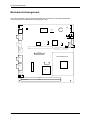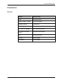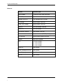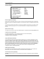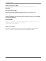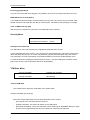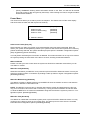
1
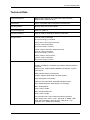
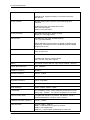
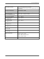
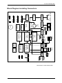
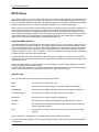
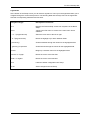
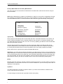
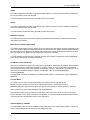
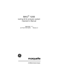
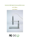
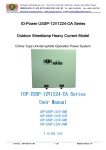
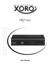
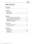
BEETLE POS Motherboard (G1-CPU-Desktop-IMP) INTEL CORE 2 DUO E6400 (65W) INTEL CORE 2 DUO E4300 (65W) INTEL PENTIUM Dual Core E2160 (65W) INTEL CELERON 440 (35W) User Manual (Edition May 2009) All brand and product names mentioned in this document are trademarks of their respective owners. The reproduction, transmission or use of this document or its contents is not permitted without express authority. Offenders will be liable for damages. All rights, including rights created by patent grant or registration of a utility model or design, are reserved. Delivery subject to availability; technical modifications possible. Copyright ©Wincor Nixdorf International GmbH, 2009 Contents Introduction............................................................................................................................................ 1 Microprocessors................................................................................................................................... 1 Chipset ................................................................................................................................................. 1 Features of the G1-CPU-DESKTOP-IMP-945G in the Beetle System................................................ 2 Mechanical dimensions of G1-CPU-DESKTOP-IMP-945G:................................................................ 3 Long term availability: .......................................................................................................................... 3 Operating systems/BIOS: .................................................................................................................... 3 Functional Blocks of G1-CPU-Desktop-IMP-945G ............................................................................. 4 Technical Data ....................................................................................................................................... 5 Plug In Cards/Risercards...................................................................................................................... 8 Block Diagram including Connectors ................................................................................................. 9 Mechanical Arrangement.................................................................................................................... 10 Connectors........................................................................................................................................... 11 External .............................................................................................................................................. 11 Internal ............................................................................................................................................... 12 Changing the CPU Battery.................................................................................................................. 13 BIOS Setup ........................................................................................................................................... 14 Standard BIOS Version...................................................................................................................... 14 BIOS Menu Bar .............................................................................................................................. 14 General Help .................................................................................................................................. 16 Scroll Bar........................................................................................................................................ 16 Sub-Menu....................................................................................................................................... 16 Info screen ......................................................................................................................................... 16 Product name: ................................................................................................................................ 17 Bios version:................................................................................................................................... 17 Ethernet MAC-Address: ................................................................................................................. 17 System, Main board, Power Supply: .............................................................................................. 17 Main Menu ......................................................................................................................................... 17 System Time [XX: XX: XX]............................................................................................................. 17 System Date [XX/XX/XXXX] .......................................................................................................... 17 Primary Master/Slave & Secondary Master/Slave ......................................................................... 18 Installed Memory: XXX MB ............................................................................................................ 19 Advanced Menu ................................................................................................................................. 20 Reset Configuration Data [No] ....................................................................................................... 20 Speaker Volume [High] .................................................................................................................. 20 Large Disk Access Mode [DOS]..................................................................................................... 20 Legacy USB Support [Enabled] ..................................................................................................... 20 USB TimeOut Value [High] ............................................................................................................ 20 Onboard LAN Controller [Enabled] ................................................................................................ 20 Onboard LAN Boot Rom [Enabled] ................................................................................................ 21 Video output to COM3 [Disabled]................................................................................................... 21 Fan Control [Automatic] ................................................................................................................. 21 Advanced Chipset Control ............................................................................................................. 21 Default Primary Video Adapter [IGD] ............................................................................................. 21 IGD – Device 2 [Auto] .................................................................................................................... 21 IGD – Device 2, Function 1 [Auto].................................................................................................. 21 DVMT 3.0 Mode [Auto]................................................................................................................... 21 Pre_Allocated Memory Size [8MB] ................................................................................................ 22 Total Graphis Memory [Turbo] ....................................................................................................... 22 DVMT Graphics Memory xxxMB.................................................................................................... 22 Azalia Audio [Auto] ......................................................................................................................... 22 USB 2.0 Support [Enabled] ............................................................................................................ 22 I/O Device Configuration ................................................................................................................ 23 Serial port A [Enabled], Serial port B [Enabled] ............................................................................. 23 Base I/O address/IRQ .................................................................................................................... 23 Touch Screen Routing [TFT Touch to COM2] ............................................................................... 23 DMI Event Logging......................................................................................................................... 23 View DMI event log [Enter]............................................................................................................. 23 Event logging [Enabled] ................................................................................................................. 24 Mark DMI events as read [Enter] ................................................................................................... 24 Clear all DMI event logs [No] ......................................................................................................... 24 Security Menu .................................................................................................................................... 24 Set Supervisor Password............................................................................................................... 24 TPM State Menu ................................................................................................................................ 24 Current TPM State: ........................................................................................................................ 24 Change TPM State: [No Change] .................................................................................................. 24 Power Menu ....................................................................................................................................... 25 After Power Failure [Stay off] ......................................................................................................... 25 Wake-on Modes ............................................................................................................................. 25 Wake-On-LAN [Disabled] ............................................................................................................... 25 Wake-On-Modem Ring [Disabled] ................................................................................................. 25 Wake-On-Time [Disabled].............................................................................................................. 25 Hardware Monitor........................................................................................................................... 26 Boot Menu.......................................................................................................................................... 26 Exit Menu ........................................................................................................................................... 27 Exit Saving Changes ...................................................................................................................... 27 Exit Discarding Changes ................................................................................................................ 27 Load Setup Defaults....................................................................................................................... 27 Discard Changes............................................................................................................................ 27 Test points codes ............................................................................................................................... 27 Additional Test points codes .............................................................................................................. 33 Abbreviations....................................................................................................................................... 34 G1-CPU-Desktop-IMP Introduction The G1-CPU-DESKTOP-IMP-945G (01750159916,MB) is the next step in the class of BEETLE-Systems. Benefit is the used new microprocessor family called Core 2 Duo with dual core technology. The two cores share up to 4MB L2 cache and communicate over a fast FSB with the 945G chipset providing enhanced graphics support. The following leading edge technologies are supported: Microprocessors INTEL CORE 2 DUO E6400 (65W) INTEL CORE 2 DUO E4300 (65W) INTEL PENTIUM Dual Core E2160 (65W) INTEL CELERON 440 (35W) Chipset Platform with chipset 945G Express Chipset with GMCH and ICH7 Enhanced internal graphic with new Graphic Engine GMA950 Use of DDR2 RAM 667 (PC5300), up to 1Gb technology Improvement of System Performance by internal Graphics and SATA II Interfaces COM 3,4 onboard 1 G1-CPU-Desktop-IMP Features of the G1-CPU-DESKTOP-IMP-945G in the Beetle System Max 8 USB ports (USB1.1 and 2.0) PCI Express x1 Interface LAN integrated onboard Min. Main Memory 256MB; Max Main Memory 4GB* Use of existing Standard-PCI Slot cards Onboard PCI connector for PCI based Plug-in modules: Secondary TFT Controller, VGA4 Controller Jumperless motherboard Support of DVD (CD-ROM) New SDVO Bridges for Panellink Interface and for DVI Interface Risercard with PCI Standard connectors Optional Risercard with PCI Express x1 Interface CRT-Bridge Dual Independend Display functionallity No support of onboard LPT1 No support of Gameport No support of analog DVD Audio No support of WLAN No support of Floppydisk No support of Line In No support of Power USB Adapter Attention: Only TFT- displays with DDC (like BA72A-2 and BA73A-2) will be supported. *Only about 3GB of system memory will be max. available, even if 4GB are assembled. 2 G1-CPU-Desktop-IMP Mechanical dimensions of G1-CPU-DESKTOP-IMP-945G: The bracket/ connector outlets of the motherboard are similar to F-series, except COM3* and COM4* are onboard. The formfactor of the bareboard is similar to the D2*- CPU. Therefore the G1-CPU-DESKTOP-IMP-945G is able to support the BEETLE/systems B/MII and B/SII. Long term availability: Mentioned CPUs and chipset 945G are supported by the INTEL IPD (Infrastructure Processor Devision) “Embedded” Group. In this way the longtime- availability is guaranteed. Operating systems/BIOS: The G1-CPU-DESKTOP-IMP-945G has complete PC functionality and supports the following operating systems: WIN/XP, WIN/XP Embedded and Linux. Features of PnP, ACPI, DMI are implemented. The size of the firmware Hub is 8Mbit. The BIOS bases on a Phoenix Core and customized POS specific functions are implemented. 3 G1-CPU-Desktop-IMP Functional Blocks of G1-CPU-Desktop-IMP-945G Core 2 Duo or Pentium Dual Core, Celeron LGA775 up to FSB1066 Mhz CRT- BRIDGE AGTL+ CHIPSET 945G GMCH GRAPHIC MEMORY CONTROLLER HUB uFCBGA 1202 pin; 34x34mm INTERNAL GRAPHICS GRAPHIC MEDIA ACCELERATOR G1 IMP SDVOBRIDGE DDR2 RAM up to 667Mhz max. 4GB for PLINK/ IF or DVI /IF DIRECT MEDIA IF SATA II IF for 2 Hard Discs ICH7 IO CONTROLLER HUB RTC, SM-BUS, IDE for DVD or CDROM mBGA 652pin, 31x31mm USB 2.0 max. 8 ports PCI – SUBMODULE ONBOARD SPI ITE 8874 P&P COM3,4 CASHDR./IF FIRMWARE HUB 8Mbit PLATFORM LAN CONNECT 82562GT 10/100Mb/s onboard SOUND CONTROLLER ALC888 LPC SUPER I/O IT8718F KEYBOARD-, MOUSE IF HW MONITOR, GPIO COM1, COM2 G1-CPU-DESKTOP-IMP-945G 4 RISERCARD Up to 3 PCI SLOTS and 2 PCI Express x1 COM3, COM4 G1-CPU-Desktop-IMP Technical Data Supported Systems BEETLE /MII, BEETLE /S-II, BEETLE/X, BEETLE/iPOS, BEETLE /MII+, BEETLE /S-II+ Architecture PC-AT compatible and POS-specific functional units Operating Modes Normal Mode, Power Save Mode Power Management ACPI 1.0, APM 1.2 Operating Systems WIN XP, WIN XP Embedded, WEPOS, WNLPOS Microprocessor INTEL Core 2 Duo E6400 processor (775 Pin LGA775 package, 65 nm technology) 2,133 GHz INTEL Core 2 Duo E4300 processor (775 Pin LGA775 package, 65 nm technology) 1,8 GHz INTEL Pentium Dual Core E2160 processor (775 Pin LGA775 package, 65 nm technology) 1,8 GHz INTEL Celeron 440 processor (775 Pin LGA775 package, 65 nm technology) 2,0 GHz Chipset INTEL chipset 945G/ICH7: Graphic and Memory Controller Hub (GMCH) with the following functions: Memory Cntrl. supports DDR2 SDRAM with 667MHz System memory bus, UMA (Unified Memory Architecture), Graphic supports 2D and 3D and video streams Plug and Display Functionality Video memory with INTEL Embedded Graphics Driver max. 224MB (Dynamic Video Memory Technology) Max. 3D Resolution: 1600 x 1200 x 32 Bit Max. Overlay Resolutoin: 2048 x 1536 x 32 Bit I/O Controller Hub 7 (ICH7) with the following functions: LAN 10/100 Cntrl., SATA – Cntrl., IDE-Cntrl. w/ UDMA, USB Cntrl. UHCI and EHCI, Interrupt-Cntrl., DMA-Cntrl., LPCInterface, RTC, SMBus-Host interface 5 G1-CPU-Desktop-IMP Super I/O IT8718F: 2 Serial Ports, Keyboard Interface, PS/2 Mouse Interface, HW-Monitor Sound controller ALC888 Audio Codec controller with the following HDA functions: 24 Bit Stereo DAC and 20 Bit Stereo ADC Mono Mic Input (MIC) Stereo Line-Level Output Sound connection Mono Microphone Input, Stereo Speaker Output (2 x 1,25 W@ 8 Ohm) Main Memory 256 MB up to max. 4GB, 2 DIMM (240pin), 1.8 V (~3 GB available) DDR2 SDRAM technology based on 256Mb, 512Mb and 1Gb technology, unbuffered non ECC, DDR2-667 Standard DIMM Height up to 35 mm Riser-Card Interface PCI-Bus (32 bit interface, 33MHz) PCI Express 1.0a, PCIe 1x (One slot) BIOS Firmware Hub: 8Mb 1024KB Flash Memory, Phoenix BIOS, PnP, PCI Rev.1.0A, DMI -support Battery 3 V Lithium for RTC and SIO Type: Sanyo CR2032 , 220 mAh System Bus Frequency max. 1066MHz RAM Bus Frequency 667MHz PCI Bus Frequency PCI 2.1, 33 MHz Wake On feature Wake On LAN, Wake On MODEM, Wake On Time Keyboard connection PC-AT compatible PS/2-Mouse connection via Y-cable together with keyboard, optional internal connection Serial interfaces COM1, COM2*, COM3*, COM4* Loudspeaker AT-compatible, volume control defined by BIOS Setup in three steps: high- , medium- , low volume compatible; foil connector DVD connection (IDE) Local Bus IDE interface, for 2 drives, PIO Mode 0 - Mode 4, ULTRA DMA Mode 0 – Mode 3, 2mm connector Hard disk connection (SATA II) 2 ports , 3.0Gb/s USB connection general: USB1.1, USB 2.0 USB1, 2: Standard 2 port connector, series A USB3-5: not implemented USB 6-8: 1 x 6 pin header (USB8 used for USB- Hub) 6 G1-CPU-Desktop-IMP Cash Drawer connection up to 2 cash drawers can be connected, Connection via RJ12 connector at Power supply (only for one cash drawer) PCI Plug-in card interface 32 bit interface, 33 MHz Status display connection Support for LEDs: Power On and HD activity Current Consumption (G1 CPU Standard 2GB RAM +3,3 V tbd, + 5 V tbd, + 12 V tbd Max. Current for keyboard +5V: Max. Current per port (for COM2*,3*,4*) +12V: 600 mA Max. Current in total (for COM2*,3*,4*) +12V: 900 mA Max. Current per port (for COM2*,3*,4*) + 5V: 300 mA Max. Current in total (for COM2*,3*,4*) + 5V: 500 mA Max. Current per port Standard USB + 5V: 500 mA Max. Current in total Standard USB + 5V: 2,0 A Fuses (Polyswitches): +5V 500 mA COM2*, COM3*, COM4*, USB1, USB2, Keyboard, Mouse +12V COM2*, COM3*, COM4* Board Dimensions about 255mm x210mm 7 G1-CPU-Desktop-IMP Plug In Cards/Risercards The following Plug In modules have been developed in the past and are available. They may be used on the G1-CPU-DESKTOP-IMP-945G. Secondary TFT Controller CRT Bridge Risercard with Standard-PCI Interfaces Optional Risercard with PCIe 1x New SDVO Bridge for PLink and DVI The following Plug In modules may not be used: LAN module (INTEL) LAN module(REALTEK) WLAN module USBplus adapter (12V) (USB 2.0) USBplus adapter (24V) (USB 2.0) COM3*,COM4* adapter (PnP) 8 COM2* Risercard Interface 2x82pol RS232 Interface SDVO CRT COM1 2x19pol 2x8pol l Loudspeaker 1x4po l Status Display1x4po Voltage Regulator ISL6326CR SATA Interface 1x7pol 1x7pol SATA II Interface PCI Onboard IDE Interface 2x20pol IDE Interface Graphic & Memory Controller Hub GMCH 945G DDR2-RAM 2 DIMMs 667MHz Clock Synthesizer ICS95420 USB Interface USB1 USB2 2x4pol PUSB COM4* Interface 2x22pol COM3* USB 3+4 2x5pol USB 3-8 Interface PCI Serial Port Controller IT8874F I/O Controller Hub ICH7 82801GB Core 2 Duo Pentium Dual Core Celeron 2x9po l PSU1 PSU1 HDA ALC888 Cashdrawer Interface 1x4po l FAN2 1x4po l FAN1 1x4po l Mouse Stereo Amplifier ILA2025B 2x10pol 2x5po l PUSB 1x4po l PON 1x6po l USB6 1x6po l USB7 1x6po Speaker Microfon l USB8 LAN 10/100 3,5mm Stereo 3,5mm Mono LAN 82562GT Keyboard Mouse 6pol Mini DIN Super I/O IT8718F NVRAM Firmware Hub 8Mbit SPI 3V Lithium 2x2po l ATX G1-CPU-Desktop-IMP Block Diagram including Connectors Main board G1-CPU-Desktop-IMP 9 G1-CPU-Desktop-IMP Mechanical Arrangement SATA2 The CPU comprises of the printed circuit board with connectors for all external peripheral connections and for installing the optional plug in cards. MIC Super IO IT 8718F KYB/ MSE SATA1 MS/E Battery BIOS SPI PWO POW1 ICH7 Fan 1 PCI IDE USB1/ USB2 PCI-ONBOARD CPU Socket 775 COM3* COM4* SDVO CRT GMCH LAN 10/100 SPK OUT DIMM0 DIMM1 10 POW2 IT USB 8 USB3+4 LED COM2* USB6 Fan 2 COM1 USB 7 LS P ATXPWR G1-CPU-Desktop-IMP Connectors External Interface Connector-Type COM1 9 pin D-sub male COM2*, COM3*, COM4* 9 pin D-sub female Keyboard, Mouse 6 pin Mini Din USB1, USB2 Standard Series Stack A CRT (with CRT-Bridge) 15 pin HDD-sub female TFT (with new PLINK Bridge) 40 pin Mini Delta Ribbon LAN 8 pin RJ45 female Line Out 3,5 mm female Microphone 3,5 mm female 11 G1-CPU-Desktop-IMP Internal 12 Interface Connector-Type DDR2-DIMMs 2 x 240 pin micro edge connector DVD (IDE) 44 pin header, 2mm Harddisk (SATA II) 7 pin Standard SATA header CRT-Bridge 16 pin Header, 2.54 mm PLINK- /DVI- Bridge 38 pin Header, 2.54 mm USB 3,4 2 x 5 pin Header, 2.54 mm USB 6,7,8 1 x 6 pin Header PS/2-Mouse external 4 pin Header, 2.54 mm Risercard 164 pin connector (PCI Express type) PCI Onboard 80 pin board to board connector Speaker 4 pin Dubox Header PSU 2 x 10 pin Header 2 x 9 pin Header 2 x 5 pin Header 2 x 2 pin Header Power On 4 pin Header System Management Bus 4 pin Header Status Display 4 pin Dubox Header Fan 1,2 4 pin Header G1-CPU-Desktop-IMP Changing the CPU Battery The BEETLE POS systems are equipped with a lithium battery on the CPU board (see page 10) to ensure data retention, the time and the setup parameters. The battery should be changed approximately every five years. When inserting the new battery, make sure the polarity is correct. This is marked in the socket. Incorrect replacement of the battery may lead to the danger of explosion. The battery is located in a socket in the CPU. To gain access to the battery, proceed as described in the according chapters of your BEETLE User Manual. See: http://www.wincor-nixdorf.com/internet/uk/Services_26Support/Support/TechnicalSupport/ POSSystems/Manuals/index.html The lithium battery must be replaced only by identical batteries or types recommended by Wincor Nixdorf International. You can return the used batteries to your Wincor Nixdorf International sales outlet. Batteries containing harmful substances are marked accordingly. The chemical denotations are as follows: CD = Cadmium; Pb = Lead, Li = Lithium. This symbol on a battery tells you that batteries containing harmful substances must not be disposed of as household waste. Follow the country specific laws and regulations. Within the European Union you are legally bound to return these batteries to the service organization where you purchased the new battery. The setup parameters must be reset each time the battery has been changed. 13 G1-CPU-Desktop-IMP BIOS Setup The Celeron, Pentium, and Core 2 Duo main board comes with a Phoenix BIOS chip that contains the ROM Setup information of your system. This chip serves as an interface between the processor and the rest of the main boards components. This section explains the information contained in the Setup program and tells you how to modify the settings according to your system configuration. Even if you are not prompted to use the Setup program, you might want to change the configuration of your system in the future. For example, you may want to enable the Security Password Feature or make changes to the power management settings. It will then be necessary to reconfigure your system using the BIOS Setup program so that the system can recognize these changes and record them in the CMOS RAM or the FLASH ROM. All setup data is stored in a non volatile memory (CMOS RAM). If you remove the CMOS battery, all parameters will be lost. Standard BIOS Version The BIOS ROM of the system holds the Setup utility. When you turn on the system, it will provide you with the opportunity to run this program. This appears during the Power-On Self Test (POST). Press <F2> to call the Setup utility. If you are a little bit late pressing the mentioned key, POST will continue with its test routines, thus preventing you from calling Setup. If you still need to call Setup, reset the system by pressing <Ctrl> + <Alt> + <Delete>. You can also restart by turning the system off and then on again. But do so only if the first method fails. The Setup program has been designed to make it as easy as possible. It is a menu-driven program, which means you can scroll through the various sub-menus and make your selections among the predetermined choices. When you invoke Setup, the main program screen will appear. On the following pages you will read more information about the Setup entries. Because the BIOS software is constantly being updated, the following BIOS screens and descriptions are for reference purposes only and may not reflect your BIOS screens exactly. BIOS Menu Bar The top of the screen has a menu bar with the following sections: INFO Use this menu for information only MAIN Use this menu to make changes to the basic system configuration. ADVANCED Use this menu to enable and make changes to the advanced features. TPM State (Note1) Use this menu to setup an optional TPM security module. SECURITY Use this menu to enable a supervisor password. POWER Use this menu to configure and enable Power Management features. BOOT Use this menu to configure the default system device used to locate and load the Operating System. EXIT Use this menu to exit the current menu or specify how to exit the Setup program. Note1: This entry is available only, if optional TPM security module is mounted To access the menu bar items, press the right or left arrow key on the keyboard until the desired item is highlighted. 14 G1-CPU-Desktop-IMP Legend Bar At the bottom of the Setup screen you will notice a legend bar. The keys in the legend bar allow you to navigate through the various setup menus. The following table lists the keys found in the legend bar with their corresponding alternates and functions. Navigation Key(s) Description of Functions <F1> Displays the General Help screen from anywhere in the BIOS Setup. <Esc> Jumps to the Exit menu or returns to the main menu from a submenu. or (keypad arrows) Select the menu item to the left or right. or (keypad arrows) Moves the highlight up or down between fields. - (minus key) Scrolls backward through the values for the highlighted field. + (plus key) or spacebar Scrolls forward through the values for the highlighted field. <Enter> Brings up a selection menu for the highlighted field. <Home> or <PgUp> Moves the cursor to the first field. <End> or <PgDn> Moves the cursor to the last field. <F9> Loads the default configuration into Setup. <F10> Saves changes and exits Setup. 15 G1-CPU-Desktop-IMP General Help In addition to the Item Specific Help window, the BIOS setup program also provides a General Help screen. This screen can be called from any menu by simply pressing <F1> or the <Alt> + <H> combination. The General Help screen lists the legend keys with their corresponding alternates and functions. Scroll Bar When a scroll bar appears to the right of a help window, it indicates that there is more information to be displayed that will not fit in the window. Use <PgUp> and <PgDn> or the up and down keys to scroll through the entire help document. Press <Home> to display the first page, press <End> to go to the last page. To exit the help window, press <Enter> or <Esc>. Sub-Menu Note that a right pointer symbol appears to the left of certain fields. This pointer indicates that a submenu can be launched from this field. A sub-menu contains additional options for a field parameter. To call a sub-menu, simply move the highlight to the field and press <Enter>. The sub-menu then will appear immediately. Use the legend keys to enter values and move from field to field within a submenu just as you would do within a menu. Use the <Esc> key to return to the main menu. Take some time to familiarize yourself with each of the legend keys and their corresponding functions. Practice navigating through the various menus and sub-menus. If you accidentally make unwanted changes to any of the fields, use the set default hot key <F9>. While moving around through the Setup program, note that explanations appear in the Item Specific Help window located to the right side of each menu. This window displays the help text for the currently highlighted field. Info screen When the Setup program is accessed, the following screen appears: Product name: Bios version: G1-CPU-IMP xx/yy mm/dd/yyyy Ethernet MAC-Address: 00-03-56-xx-yy-zz System: ----------------------------------------------------------------------------- Main board: ----------------------------------------------------------------------------- Power Supply: ----------------------------------------------------------------------------- This screen is for information only. There is nothing that could be changed within Setup. All information is intended to facilitate the support of your system. 16 G1-CPU-Desktop-IMP Product name: This text is fixed for your main board with standard BIOS. This board is also called “G1-CPU-IMP”. Bios version: The Bios version is displayed in the release format xx/yy, followed by date of release in international format. Ethernet MAC-Address: The Ethernet MAC-Address of the Onboard LAN Controller is displayed at this line. System, Main board, Power Supply: The default placeholders may be replaced by specific data from factory, describing configuration, serial number etc. for each device. Main Menu System Time: System Date: [08:14:46] [02/20/2009] IDE Primary/Master IDE Primary/Slave IDE Secondary/Master IDE Secondary/Slave 120GB SATA1] [None] [None] [None] Installed Memory: 1024 MB System Time [XX: XX: XX] Sets your system to the time that you specify (usually the current time). The format is hour, minute, second. Valid values for hour, minute, and second are: Hour: (00 to 23), Minute: (00 to 59), Second: (00 to 59). Use the <Tab> or <Shift> + <Tab> keys to move between the hour, minute, and second fields. System Date [XX/XX/XXXX] Sets your system to the date that you specify (usually the current date). The format is month, day, year. Valid values for month, day, and year are: Month: (1 to 12), Day (1 to 31), Year: (up to 2079). Use the <Tab> or <Shift> + <Tab> keys to move between the month, day, and year fields. 17 G1-CPU-Desktop-IMP Primary Master/Slave & Secondary Master/Slave The first 2 lines are info lines about the attached S-ATA hard disks, while the next two are using for the P-ATA disks. Note: Before attempting to configure a hard disk drive, make sure you have the configuration information supplied by the manufacturer of the drive. Incorrect settings my cause your system not to recognize the installed hard disk. To allow the BIOS to detect the drive type automatically, select [Auto]. Type: [Auto] LBA Format Total Sectors Maximum Capacity 234441648 120GB SATA1 Multi-Sector Transfers: LBA Mode Control: 32 Bit I/O: Transfer Mode: Ultra DMA Mode [16 Sectors] [Enabled] [Disabled] [Fast PIO 4] [Mode 5] Type [Auto] Select [Auto] to automatically detect an IDE hard disk drive. If automatic detection is successful, the correct values will be filled in for the remaining fields on this sub-menu. If automatic detection fails, your hard disk drive may be too old or too new. You can try updating your BIOS or enter the IDE hard disk drive parameters manually. After the IDE hard disk drive information has been entered into BIOS, new IDE hard disk drives must be partitioned (e.g. with FDISK) and then formatted before data can be read from and written to. Primary IDE hard disk drives must have its partition set to active (also possible with FDISK). Other options for the Type field are: [None] to disable IDE devices. Important: If your hard disk was already formatted on an older previous system, incorrect parameters may be detected. You will need to enter the correct parameters manually or use low-level format if you do not need the data stored on the hard disk. If the parameters listed differ from those used when the disk was formatted, the disk will not be readable. If the auto detected parameters do not match those that should be used for your disk you should enter the correct ones manually by setting [User]. [User] Manually enter the number of cylinders, heads and sectors per track for your drive. Refer to your drive documentation or to the label on the drive. If no drive is installed or if you are removing a drive and not replacing it, select [None]. Cylinders This field configures the number of cylinders. Refer to your drive documentation to determine the correct value to enter into this field. To make changes to this field, the Type field must be set to [User]. 18 G1-CPU-Desktop-IMP Heads This field configures the number of read/write heads. Refer to your drive documentation to determine the correct value to enter into this field. To make changes to this field, the Type field must be set to [User]. Sector This field configures the number of sectors per track. Refer to your drive documentation to determine the correct value to enter into this field. To make changes to this field, the Type field must be set to [User]. Maximum Capacity This field shows the drive’s maximum capacity calculated automatically by the BIOS from the drive information you entered. Multi-Sector Transfers [Maximum] This option automatically sets the number of sectors per block to the highest number supported by the drive. This field can also be configured manually. Note that when this field is configured automatically, the value set may not always be the fastest value for the drive. Refer to the documentation that came with your hard drive to determine the optimal value and set it manually. To make changes to this field, the Type field must be set to [User]. Configuration options: [Disabled] [2 Sectors] [4 Sectors] [8 Sectors] [16 Sectors]. LBA Mode Control [Enabled] Select the hard disk drive type in this field. When Logical Block Addressing is enabled, 28-bit addressing of the hard drive is used without regard to cylinders, heads, or sectors. Note that Logical Block Access may decrease the access speed of the hard disk. However, LBA Mode is necessary for drives with more than 504MB of storage capacity. Configuration options: [Enabled] [Disabled]. 32 Bit I/O [Disabled] This field setting enables or disables the 32 Bit IDE data transfers. Configuration options: [Disabled] [Enabled]. Transfer Mode This option lets you set a PIO (Programmed Input/Output) mode for the IDE device. Modes 0 trough 4 provide successively increased performance. Configuration options: [Standard] [Fast PIO 1] [Fast PIO 2] [Fast PIO 3] [Fast PIO 4] [FPIO 3 / DMA 1] [FPIO 4 / DMA 2]. Other options for Type are: [CD-ROM] for IDE CD-ROM drives After using the legend keys to make your selections in this sub-menu, press the <Esc> key to exit back to the Main menu. When the Main menu appears, you will notice that the drive size is indicated in the field for the hard disk drive that you just configured. Installed Memory: XXX MB This field displays the amount of installed memory detected by the system during bootup. You do not need to make changes to this field. This is a display only field. 19 G1-CPU-Desktop-IMP Advanced Menu Reset Configuration Data: Speaker Volume Large Disk Access Mode: Legacy USB Support: USB TimeOut Value: Onboard LAN Controller: Onboard LAN BootRom: Video output to COM3: Fan Control: [No] [High] [DOS] [Enabled] [High] [Enabled] [Enabled] [Disabled] [Automatic] Advanced Chipset Control I/O Device Configuration DMI Event Logging Reset Configuration Data [No] [Yes] erases all configuration data in a section of memory for ESCD (Extended System Configuration Data) which stores the configuration settings for non-PnP Plug-in devices. Configuration options: [No] [Yes] If you are facing problems after adding or removing any hardware components to the system it might be wise to select the [Yes] option once. This allows the BIOS to reconfigure available hardware resources. Speaker Volume [High] This field is for the volume control of the installed speaker. Configuration options [High] [Middle] [Low]. Large Disk Access Mode [DOS] For UNIX, Novell Netware, or other operating systems you have to select [Other]. For DOS or Windows use the value of default [DOS]. Configuration options: [DOS] [Other]. Legacy USB Support [Enabled] This motherboard supports Universal Serial Bus (USB) devices. The default of [Disabled] the USB controller is disabled no matter whether you are using a USB device or not. The enabling of the controller will run with the help of a USB compliant operating system like Windows XP or else. If the point stands on [Enabled] the legacy USB support from the BIOS is started. Now it is possible to use a USB keyboard to start this setup or with the standard DOS environment. If you like to use a USB-Floppy disk or a USB CD-ROM device for booting, you have to enable this setup point and after detecting of this USB device from the BIOS, you have to switch the boot order to the appropriate device. Configuration Options: [Disabled] [Enabled] USB TimeOut Value [High] Some USB device uses longer time to initialize. If all devices are fast enough, you can switch this setup point to Low to get a shorter boot time. Configuration Options: [High] [Low] Onboard LAN Controller [Enabled] This point switches physical on or off the Onboard LAN Controller. Configuration Options: [Disabled] [Enabled] 20 G1-CPU-Desktop-IMP Onboard LAN Boot Rom [Enabled] This point switches on or off the PXE PROM from the onboard LAN Controller. Configuration Options: [Disabled] [Enabled] Video output to COM3 [Disabled] Some systems may be configured without a full screen display, just using a small display connected to the COM3 serial port. [Enabled] will redirect diagnostic information during PowerOnSelfTest to this serial port, giving control about the system to smaller displays as well. Fan Control [Automatic] This setup mode will control the speed of the PWM-Fans due to actual CPU-Temperature if setting to Automatic. With Max Cooling is the speed of the fans always high. AutoSmooth will work with time hysteresis and smaller steps speeding up and down. Configuration Options: [MAX Cooling] [Automatic] [AutoSmooth] Advanced Chipset Control Default Primary Video Adapter IGD – Device 2: IGD – Device 2, Function 1: DVMT 3.0 Mode Pre-Allocated Memory Size: Total Graphics Memory: DVMT Graphics Memory: [IGD] [Auto] [Auto] [Auto] [8MB] [Turbo] 216MB Azalia Audio [Auto] USB 2.0 Support [Enabled] Default Primary Video Adapter [IGD] Select IGD to have Internal Graphics Device, if supported and enabled, to be used as boot display device. Select PCI to have PCI Graphics to be used for the boot display. Configuration options:[IGD] [PCI]. IGD – Device 2 [Auto] Enables or disables the second Function of the internal graphic device Configuration options:[Disabled] [Auto]. IGD – Device 2, Function 1 [Auto] Configuration options: [Disabled] [Auto]. DVMT 3.0 Mode [Auto] The configuration of the internal graphic memory is selectable for different internal modes. Configuration options:[Auto] [Fixed] [DVMT] [Combo]. 21 G1-CPU-Desktop-IMP Pre_Allocated Memory Size [8MB] Select the amount of Pre-allocated graphic memory for use by the internal graphic device. Configuration options: [1MB] [8MB]. Total Graphis Memory [Turbo] Select the amount of main memory that the internal graphic device will use during runtime. Configuration options:[Turbo] [64MB] [128MB]. DVMT Graphics Memory xxxMB This entry is an info field to show the maximum amount of memory the Internal Graphics Device (IGD) is using from the main memory. Azalia Audio [Auto] Setting item to Auto will allow the onboard audio to operate properly. Setting item to disabled will remove the onboard audio controller from PCI config space. Configuration options:[Disabled] [Auto]. USB 2.0 Support [Enabled] Using USB devices complying 2.0 standard, let this field be Enabled. Due to lack of appropriate drivers you may switchback to Disabled. Configuration options: [Disabled] [Enabled]. 22 G1-CPU-Desktop-IMP I/O Device Configuration Serial port A: Base I/O address/IRQ: Serial port B: Base I/O address/IRQ: [Enabled] [3F8/IRQ 4] [Enabled] [2F8/IRQ 3] Touch Screen Routing: [TFT Touch to COM2] Serial port A [Enabled], Serial port B [Enabled] These fields configure the Serial ports directly. Configuration options: [Disabled] [Enabled]. Base I/O address/IRQ Set the base I/O address and interrupt line for the onboard serial connector.. Configuration options: [3F8/IRQ 4] [3E8/IRQ 4] [2F8/IRQ 3] [2E8/IRQ 3]. Touch Screen Routing [TFT Touch to COM2] Using a Touch Screen you may select routing it to a serial interface using hardware lines instead of COM1 or COM2. Configuration Options: [No Routing] [TFT Touch to COM1] [TFT Touch to COM2] [. PCI Touch to COM1] [PCI Touch to COM2] [TFT&PCI to COM(1&2)]. [TFT&PCI to COM(1&2)] means: TFT will be routet to COM1, PCI will be routet to COM2. DMI Event Logging Event log validity Event log capacity Valid Space available View DMI event log Event Logging [Enter] [Enabled] Mark DMI events as read Clear all DMI event logs [Enter] [No] Desktop Management Interface (DMI) is a method of managing computers in an enterprise. Using DMI, a system administrator can obtain the types, capabilities, operational status, installation date and other information about the system components. An event log is a fixed-length area within a nonvolatile storage element. View DMI event log [Enter] This setup point is useful to display the recorded DMI events like a defect floppy disk controller or anything else. If there is an error stored, the BIOS will display a message every time the system is starting up. 23 G1-CPU-Desktop-IMP Event logging [Enabled] If you do not use the DMI event logging, it is possible to shut off the recording mechanism of errors. Mark DMI events as read [Enter] If you dislike the BIOS message at system starting up but you like to have the errors recorded, mark all DMI events as read. With the next start up of the system, the BIOS would not display a message. Clear all DMI event logs [No] With this point it is possible to clear all the recorded DMI events manually. Security Menu Supervisor Password Is: Clear Set Supervisor Password [Enter] Set Supervisor Password This field allows you to set the password. Highlight the field and press <Enter>. Type a password and press <Enter>, you can type up to eight alphanumeric characters. Symbols and other characters are ignored. To confirm the password, type the password again and press <Enter>. The password is now set to [Enabled]. This password allows full access to the BIOS Setup menu. To clear the password, highlight this field and press <Enter>. The same dialog box as above will appear. Press <Enter> and the password will be set to [Disabled]. TPM State Menu Current TPM State: Enabled and Activated Change TPM State [No Change] Current TPM State: This is field informs about the actual state of the TPM module. Change TPM State: [No Change] Select the TPM changes after the next automated reboot of the system. 24 - [No Change]: The TPM state will be untouched. - [Enable & Activate]: This action will switch on the TPM logical. - [Deactivate & Disable]: This action will switch off the TPM logical. WARNING! Doing so might prevent security applications that rely on the TPM from functioning as expected. G1-CPU-Desktop-IMP - [Clear]: WARNING! Clearing erases information stored on the TPM. You will lose all created keys and access to data encrypted by these keys. After clearing the TPM, it will get the status deactivated & disabled. Power Menu The Power menu allows you to reduce power consumption. This feature turns off the video display and shuts down the hard disk after a period of inactivity. After Power Failure: [Stay Off] Wake On LAN: Wake On Modem Ring: Wake On Time: [Disabled] [Disabled] [Disabled] Hardware Monitor: After Power Failure [Stay off] Select whether you want your system to be rebooted after power has been interrupted. [Stay off] leaves your system off and [Restore] reboots your system if it was active before power loss. Is the key [Follow AC/Power] selected, the system will startup anytime power is available. Configuration options: [Stay off] [Restore] [Follow AC/Power]. In mode [Follow AC/Power] the front button is disabled. This means that there is no way to force down the system pressing the front button more than 4 seconds, avoiding accidental shutdown. Wake-on Modes Please note that you have to shut down the system into Soft-Off or Hibernate mode before you can use Wake-on modes. Wake-On-LAN [Disabled] Wake-On-LAN allows your BEETLE to be powered up from Soft-Off or Hibernate mode. This may be done from another system via a network by sending a wake-up frame or signal. Configuration options: [Disabled] [Enabled]. Wake-On-Modem Ring [Disabled] This allows to enable or disable powering up the BEETLE when the modem receives a call while the BEETLE is in Soft-Off or Hibernate mode. NOTE: The BEETLE cannot receive or transmit data until the system and applications are fully running, thus connection cannot be made on the first try. Turning an external modem off and then back on while the BEETLE is off causes an initialization string that will cause the system to power on. Configuration options: [Disabled] [Enabled]. Wake-On-Time [Disabled] This allows an unattended or automatic system power up from Soft-Off or Hibernate mode. You may configure your system to power up at a certain time. The wake-up time is to be set in the next field below this field. Configuration options: [Disabled] [Enabled] 25 G1-CPU-Desktop-IMP Hardware Monitor CPU Temperature: Board Temperature: 42 ˚C 35 ˚C Fan_1 Fan_2 Fan_PowerSupply 4448 rpm 5480 rpm 2790 rpm Core Voltage +1.8V Voltage +3.3V Voltage +VCC Voltage +12V Voltage -12V Voltage +1.5V Voltage +5VSB Voltage VBatt Voltage 1.26 V 1.82 V 3.39 V 5.26 V 12.48 V 12.03 V 1.48 V 5.18 V 3.0 V CPU Temperature [xx °C] The onboard hardware monitor is able to detect the motherboard and CPU temperatures (for supported processors only). CPU Fan_x Speed [xxxx rpm] The onboard hardware monitor is able to detect the CPU fan speed and power supply fan speed in rotations per minute (rpm). The presence of the fans is automatically detected. Several Voltages [xx.x V] The onboard hardware monitor is able to detect the voltage output by the onboard voltage regulators. Boot Menu Boot 1: 2: 3: 4: 5: 6: 7: 8: Excluded : : : : : : : priority order: USB FDC: USB CDROM : IDE CD : USB HDD : IDE 0 : IDE 1 : IDE 2 : PCI LAN : from boot order IDE 3 : USB Key : USB ZIP : PCI SCSI PCI : Legacy Network Card: UNKNOWN: The Boot menu allows you to select from the four possible types of boot devices listed using the up and down arrow keys. By using the <+> or <Space> key, you can promote devices and by using the <-> key, you can demote devices. Promotion or demotion of devices alters the priority which the system uses to search for a boot device on system power up. 26 G1-CPU-Desktop-IMP Exit Menu Exit Saving Changes Exit Discarding Changes Load Setup Defaults Discard Changes Once you have made all your selections from the various menus in the Setup program, you should save your changes and exit Setup. Select Exit from the menu bar to display the following menu. <Esc> does not exit this menu. You must select one of the options from this menu or <F10> from the legend bar to exit this menu. Exit Saving Changes Once you have finished making selections, choose this option from the Exit menu to ensure the values you selected are saved to the CMOS RAM. The CMOS RAM is sustained by an onboard backup battery and stays on even when the BEETLE is turned off. Once this option is selected, a confirmation is asked. Select [Yes] to save changes and exit. Exit Discarding Changes This option should only be used if you do not want to save the changes you have made to the Setup program. If you have made changes to fields other than system date, system time, and password, the system will ask for confirmation before exiting. Load Setup Defaults This option allows you to load the default values for each of the parameters on the Setup menu. When this option is selected or if <F9> is pressed, a confirmation is requested. Select [Yes] to load default values. You can now select Exit Saving Changes or make other changes before saving the values to the non-volatile RAM. Discard Changes This option allows you to discard the selections you made and restore the values you previously saved. After selecting this option, a confirmation is requested. Select [Yes] to discard an changes and load the previously saved values. Test points codes At the beginning of each POST routine, the BIOS outputs the test point error code to I/O port address 80h. Use this code during trouble shooting to establish where the system failed and what routine has been performed. If the BIOS detects a terminal error condition, it halts POST after issuing a terminal error beep code and attempting to display the error code on the port 80h LED display (diagnostic card). If the system hangs before the BIOS can process the error, the value displayed at the port 80h is the last test performed. In this case, the screen does not display the error code. The routine derives the beep code from the test point error as follows: 1. The 8-bit error code is broken down to four 2-bit groups. 27 G1-CPU-Desktop-IMP 2. Each group is made one-based (1 through 4) by adding 1. 3. Short beeps are generated for the number in each group. Example: Test point 1Ah = 00 01 10 10 = 1-2-3-3 beeps The following is a list of the checkpoint codes written out to the diagnostic port at the start of each test. The first beep code inside of the BIOS has 1-long and 2-short beeps. This means that there is a problem with the graphic adapter. POST Code (Hex) 02h 28 Name Description VERIFY_REAL IF <in port mode> THEN Turn on A20 Reset Processor ENDIF Disable non-maskable Interrupts IF <cold boot> THEN Store reset DX value in CMOS Determine CPU manufacturer and type Store CPU manufacturer and type in CMOS ENDIF Reset all DMA controllers. Disable all video controllers. Clear any pending interrupts from the RTC Set up port 61h to speaker off and timer gate enabled. Set DRAM controller registers to values that are needed for DRAM discovery and testing. Set bit in CMOS indicating that POST is in progress. Not cleared until Post Code Aeh. Set CPU configuration registers. Turns on the CPU cache. Set L2 cache controller registers to values needed for SRAM discovery and testing. IF <onboard super I/O exists> THEN Turn Off LPT and COM ports in super I/O. Set I/O controller registers to default values. ENDIF IF <secondary IDE controllers exists> THEN Set secondary IDE controller configuration registers to default values. ENDIF IF <power management enabled> THEN Set the power management configuration registers to default values. ENDIF Set Cx5520 configuration registers to default values. Set any other configuration registers to default values. Return to real mode. Early reset of PCI devices required to disable bus masters. Assumes the presence of a stack and running from decompressed shadow memory. Verify 8742 (keyboard controller) is responding. Improper connections/timing to the 8742. Send self test command to 8742. 03h 04h DISABLE_NMI GET_CPU_TYPE 06h HW_INIT 08h CS_INIT 09h SET_IN_POST 0Ah 0Bh 0Ch CPU_INIT CPU_CACHE_ON CACHE_INIT 0Eh IO_INIT 0Fh FDISK_INIT 10h PM_INIT 11h REG_INIT 12h 13h RESTORE_CR0 PCI_BM_RESET 14h 8742_INIT G1-CPU-Desktop-IMP POST Code (Hex) 16h Name Description CHECKSUM Checksum the system BIOS ROM IF <checksum is incorrect> THEN Halt. ENDIF Initialize external cache before autosizing memory. Initialize all three of the 8254 timers. Initialize the DMA command register and all 8 DMA channels. Initialize the 8259 interrupt controller. Copy test code to RAM and execute that code looking for refresh bit in port 61h to toggle. IF <refresh test failed> THEN Halt. ENDIF Read 8742 self-test results. IF <self-test failed> THEN Halt. ELSE Read system info from 8742 Set 8742 command byte. ENDIF Go into protected mode. Set ES, DS, SS, FS, and GS to 4Gb. Determine the size of each DRAM bank. Set DRAM controller configuration registers to enable DRAM. Initialize the POST Memory manager. Clear the 512k of DRAM. Test for stuck address line in lower 1M of address space, IF <test failed> THEN Halt. ENDIF Test for stuck DRAM data line by walking a 1 through all bit locations of address 0 and then walking a 0 through. IF <test failed> THEN Halt. ENDIF Clears the cache before shadowing the system. Determine the CPU core speed by timing the execution of a loop. Initialize the Phoenix Dispatch Manager. Clear CMOS diagnostic byte. IF <CMOS battery is dead> THEN Set “bad battery” flag in CMOS IF <CMOS checksum is bad> THEN Set “bad CMOS check” flag in CMOS Checksum CMOS ENDIF ENDIF Vector to proper shutdown routine (reset). Copy system BIOS ROM to shadow RAM. Detect the amount of SRAM for the L2 cache. Set L2 cache controller configuration registers to enable SRAM. 17h 18h 1Ah PRE_SIZE_RAM TIMER_INIT DMA_INIT 1Ch 20h RESET_PIC REFRESH 22h 8742_TEST 24h SET_HUGE_ES 28h SIZE_RAM 29h 2Ah 2Ch MEM_MGR_INIT ZERO_BASE_RAM ADDR_TEST 2Eh BASERAML 2Fh 32h PRE_SYS_SHADOW COMPUTE_SPEED 33h 34h PDM_INIT CMOS_TEST 36h 38h 3Ah CHK_SHUTDOWN SYS_SHADOW CACHE_AUTO 29 G1-CPU-Desktop-IMP POST Code (Hex) 3Ch 30 Name Description ADV_CS_CONFIG IF <CMOS is valid (checksum good and battery good) THEN Load DRAM controller configuration registers with values from CMOS fields. ENDIF IF <CMOS is valid> THEN Load ISA controller configuration registers with values from CMOS fields and load any other configuration registers with values from CMOS fields. ENDIF Set interrupt vectors 0-77h to BIOS general interrupt handler. Set interrupt vectors 0-20h to correct BIOS interrupt handlers. Initialize all motherboard devices. Verify that the Phoenix BIOS copyright message is correct. Initialize PCI option ROM manager. Determine video type to be used and store. Initialize PCI to PCI bridges. Reset all PCI devices. Send self test command to all PCI devices. Configure base registers of all PCI devices. Initialize all MDA video adapters. Initialize all CGA video adapters. Execute VGA option ROMs to initialize VGA adapter. Initialize VSA. Initialize Quietboot if installed. Enable IRQ0 and IRQ1. IF <video shadow enabled in setup> THEN IF <CMOS valid and last boot successful> THEN Shadow video BIOS ROM. ENDIF ENDIF Display the CPU type and speed on the screen. IF <EISA support is enabled> THEN Checksum EISA data NVRAM locations. IF <checksum good> THEN Initialize each slot. ELSE Display bad config message. ENDIF ENDIF Check for return code of AA from keyboard self-test, IF <return code not AA> THEN Set keyboard error flag ENDIF IF <keyclick enabled and keyboard good> THEN Initialize key stroke clicker ENDIF Send command to keyboard controller to enable the keyboard. Check for unexpected interrupts. Check for unexpected NMI. Enable parity checkers and check for unexpected NMI. Register POST display services with POST Dispatch Manager. 3Dh ADV_REG_CONFIG 42h VECTOR_INIT 44h SET_BIOS_INT 45h 46h CORE_DEVICE_INIT COPYRIGHT 47h 48h 49h PCI_OP_INIT CONFIG PCI_INIT 4Ah VIDEO 4Bh QUIETBOOT_START 4Ch VID_SHADOW 4Eh 51h CR_DISPLAY EISA_INIT 52h KB_TEST 54h KEY_CLICK 56h ENABLE_KB 58h HOT_INT 59h PDS_INIT G1-CPU-Desktop-IMP POST Code (Hex) 5Bh 5Ch Name Description CPU_CACHE_OFF MEMORY_TEST Disable and WB invalidate CPU cache. Determine amount of memory below 1M. Walk a1 through data bus at 80000h. walk a 0 through data bus at 80000h. Check for stuck address line from 80000h to 8FFFFh. Determine total amount of memory by doing a read/write test. For each 1M block oh memory: Walk a 1 through data bus at first location of block. Walk a 0 through data bus at first location of block. Check for stuck address line in the block. Do an extended address line test on the entire memory range. Code that is patched into the ROM can be set up to execute at this point. Load L2 cache controller configuration registers with values from setup screens. Set non-cacheable regions. Enable L1 and L2 caches. IF <cache RAM size not zero> THEN Display L2 cache RAM size on screen. ENDIF IF <system BIOS ROM shadowed> THEN Display message indicating that the system BIOS ROM is shadowed. ENDIF IF <video BIOS ROM shadowed> THEN Display message indicating that the video BIOS ROM is shadowed. ENDIF Display the starting address of the no disposable (run time) BIOS. Display error messages for any errors found. IF <system configuration error found> THEN Display message indicating configuration error detected. ENDIF Verify that the RTC is running. IF <RTC not running> THEN Set bit in RTC indicating that the time is invalid. ENDIF IF <keyboard failure detected> THEN Display message indicating keyboard failure. ENDIF Initialize hardware interrupt vectors 08h-0Fh Initialize Intelligent System Monitoring Support. IF <integrated super I/O exists> THEN Disable LPT and COM ports on integrated super I/O. ENDIF. Late initialization of devices. Identify and test all COM ports. Configure Fdisk controller. Test and ID parallel ports. Initialize PnP ISA devices. 60h EXT_MEMORY 62h EXT_ADDR 64h USERPATCH 66h CACHE_ADVNCD 68h CACHE_CONFIG 6AH DISP_CACHE 6Ch DISP_SHADOW 6Eh DISP_NONDISP 70h 72h ERROR_MSGS TEST_CONFIG 74h RTC_TEST 76h KEYBOARD 7Ch 7Dh 80h HW_INTS ISM_INIT IO_BEFORE 81h 82h 83h 84h 85h CORE_LATE_INIT RS232 CONFIG_IDE LPT PCI_PCC 31 G1-CPU-Desktop-IMP POST Code (Hex) 87h 88h 89h 8Ah 8Bh 32 Name Description POST_CONFIG_MCD BIOS_INIT ENABLE_NMI INIT_EXT_BDA MOUSE Initialize Mother Board Configurable devices. Initialize timeouts, key buffer, soft reset flag. Enable NMI. Initialize the extended BIOS data area. IF <mouse support enabled> THEN Setup interrupt vector for mouse. Add mouse support to equipment installed flag. ENDIF Test both floppy drives. IF <error detected> THEN Display floppy error message. ENDIF Count and store the number of ATA drives in the subsystem. Initialize the hard disk subsystem and test. IF <error detected> THEN Display hard disk error message. ENDIF Set timing based on drives attached. Code that is patched into the ROM can be setup to execute at this point. Create the CPU feature table. Disable the A20 address line. Validate bootable CD ROM. Prepare CD for CD ROM boot. Store an 8 in the shutdown code byte in CMOS. Reset the processor. Create pointer to MP table in Extended BDA. Scan through the ISA option ROM space and jump to each option ROM found. Shadow PCI option ROMs and initialize cards. Shadow expansion ROM areas that are enabled from setup. Setup power management if enabled. Initialize Security Engine. Enable IRQ 0, 1, 2, and 6. Check and store the total number of Fast Disks (ATA and SCSI). Verify that the system clock interrupts are occuring. Set NumLock indicator. IF <keylock set> THEN Print error message on screen. ENDIF 8Ch FLOPPY 8Fh FDISK_FAST_PREINIT 90h FDISK 91h 92h FDISK_FAST_INIT USERPATCH2 93h 94h 95h MP_INIT DISABLE_A20 CD 96h CLEAR_HUGE_ES 97h 98h MP_FIXUP ROM_SCAN 9Ah MISC_SHADOW 9Ch 9Dh 9Eh 9Fh PM_SETUP SECURITY IRQS FDISK_FAST_INIT2 A0h A2h TIME_OF_DAY KEYBOARD_TEST G1-CPU-Desktop-IMP POST Code (Hex) A4h AAh Name Description KEY_RATE SCAN_FOR_F2 Initialize keyboard typematic rate. IF <2 key was pressed during POST> THEN Set flag indicating key press. Display “Entering Setup” message. ENDIF IF <2 was pressed> THEN Enter Setup. ELSE IF <errors were found> THEN Display “Press 7 or 2” prompt. IF <2 is pressed> THEN Enter Setup. ELSE IF <7 is pressed> THEN Boot. ENDIF ELSE Boot. ENDIF Clear CMOS bit indicating POST is in progress. IF <error were found> THEN Beep twice. Display “Press 7 or 2” message. IF <2 is pressed> THEN Enter Setup. ELSE IF <7 is pressed> THEN Boot. ENDIF ENDIF Change BIOS data areas flag to indicate POST is complete. Beep once. Reset video: Clear screen, reset cursor, reload DAC. IF <password enabled> THEN Print message requesting password. IF <password incorrect> THEN Halt. ENDIF ENDIF Clear the GDT. Prepare to boot, clear the screen. Initialize DMI header and substructures. Do INT 19h to load OS. ACh SETUP_CHECK AEh B0h CLEAR_BOOT ERROR_CHECK B2h POST_DONE B4h B5h ONE_BEEP QUIETBOOT_END B6h PASSWORD B8h B9h BAh C0h SYSTEM_INIT PREPARE_BOOT DMI INT19 Additional Test points codes These test points are only available if the memory has some malfunction. POST Code [Hex] E0h E1h – EFh Description Unsupported RAM detected / No RAM installed RAM specification not valid 33 G1-CPU-Desktop-IMP Abbreviations ACPI AGTL+ APC PM AT ATA BGA BIOS CMOS CPLD CPU CRT DIMM DMA DMI DVMT DVI ECP EEPROM E-IDE EMS ESCD EPP FSB GTL HW IDE IGD LAN LBA LCD MAC NA NVRAM P-ATA POS PCI PnP POST RAM RI ROM RS SATA SLP SMI SMM SMRAM SPGA TFT TPM UPS USB UUID VGA WOL WOM 34 Advanced Configuration and Power Interface Assisted Gunning Transceiver Logic Advanced Power Control Advanced Power Management Advanced Technology AT Attachment Ball Grid Array Basic Input and Output System Complementary Metal Oxide Semiconductor Complex Programmable Logic Device Central Processing Unit Cathode-ray Tube Dual Inline Memory Module Direct Memory Access Desktop Management Interface Dynamic Video Memory Technology Digital Video Interface Extended Capabilities Port Electrical Erasable Read Only Memory Enhanced Integrated Drive Electronics Expanded Memory System Extended System Configuration Data Enhanced Parallel Port Front Side Bus Gunning Transceiver Logic HardWare Integrated Drive Electronics Internal Graphic Device Local Area Network Logical Block Addressing Liquid Crystal Display Media Access Control Power failure Non-volatile Random Access Memory Parallel AT Attachment (old version of hard disk interface) Point of Sales Peripheral Component Interconnect Plug and Play Power On Self Test Random Accessible Memory Ring Indicator Read Only Memory Retail Systems Serial AT Attachment (new version of hard disk interface) System Locked Pre-Installation System Management Interrupt System Management Mode System Management RAM Staggered Pin Grid Array Thin-film transistor Trusted Platform Module Uninterruptible Power Supply Universal Serial Bus Universal Unique IDentifier Video Graphics Array Wake On LAN Wake On Modem Wincor Nixdorf International GmbH D-33094 Paderborn Order No. / Bestell-Nr.: 01750161269