1
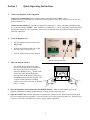
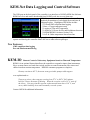
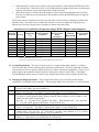
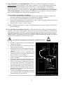
Temperature Control for Research and Industry
Digital Vacuum
Regulator
User’s Manual
Model 300
INDEX
PAGE
SECTION
1.
QUICK OPERATING INSTRUCTIONS
...........................
Safety Notices
........................ .........................
KEM-Net Data Logging and Control Software . . . . . . . . . . . . . . . . . . . . . . . . . . . .
2.
REGULATOR DESCRIPTION
3.
OPERATIONS GUIDE
.........................................
3.1
How the Regulator Works
...................................
3.2
Factors Affecting Vacuum Regulation Accuracy
.................
3.3
Ramp-to-Setpoint & Soak Feature
.............................
3.4
Use with Rotary Evaporators
.................................
3.5
Vacuum Requirements
......................................
3.6
Changing the Display Resolution
.............................
3.7
Using the Regulator for Vacuum Distillations
....................
3.8
Correcting Offset in the Displayed Pressure
.....................
..................................
3
4
5
6
7
7
7
8
9
10
10
11
11
Warranty
J-KEM Scientific, Inc. warrants this unit to be free of defects in materials and workmanship and to give satisfactory service
for a period of 6 months from date of purchase. If the unit should malfunction, it must be returned to the factory for
evaluation. If the unit is found to be defective upon examination by J-KEM, it will be repaired or replaced at no charge.
However, this WARRANTY is VOID if the unit shows evidence of having been tampered with or shows evidence of being
damaged as a result of excessive vibration, corrosive materials, or misuse. Components which wear or are damaged by
misuse are not warranted. This includes valves and fuses.
THERE ARE NO WARRANTIES EXCEPT AS STATED HEREIN. THERE ARE NO OTHER WARRANTIES,
EXPRESSED OR IMPLIED, INCLUDING BUT NOT LIMITED TO THE IMPLIED WARRANTIES OF
MERCHANTABILITY AND OF FITNESS FOR A PARTICULAR PURPOSE. IN NO EVENT SHALL J-KEM
SCIENTIFIC, INC. BE LIABLE FOR CONSEQUENTIAL, INCIDENTAL OR SPECIAL DAMAGES. THE BUYER'S
SOLE REMEDY FOR ANY BREACH OF THIS AGREEMENT BY J-KEM SCIENTIFIC, INC. OR ANY BREACH OF
ANY WARRANTY BY J-KEM SCIENTIFIC, INC. SHALL NOT EXCEED THE PURCHASE PRICE PAID BY THE
PURCHASER TO J-KEM SCIENTIFIC, INC. FOR THE UNIT OR UNITS OF EQUIPMENT DIRECTLY AFFECTED
BY SUCH BREACH.
Returns, requests for service and inquires should be directed to:
J-KEM Scientific, Inc.
6970 Olive Blvd.
St. Louis, MO 63130
(314) 863-5536
FAX (314) 863-6070
E-Mail: [email protected]
Internet on-line catalog: http://www.jkem.com
2
Section 1
1.
Quick Operating Instructions
Connect the Regulator to the Equipment
Connect the vacuum pump (or the vacuum source) to the tube marked “Inlet”. Note:
In almost all cases a needle valve is needed for accurate regulation of pressure. Place the valve on the inlet
port (see Section 3.2).
Connect the instrument that you want to regulate the vacuum in (i.e., rotary evaporator, distillation setup,
etc.) to the tube marked “Outlet”. There should be no restrictions (i.e. valves, stopcocks) between the Outlet
port and the equipment you’re regulating. Best results are obtained when large diameter tubing is used to
make this connection.
2.
Turn the Regulator On
1. Set the regulator selection switch to the
Off position.
2. If the unit is fit with a needle valve, turn
the valve until it’s fully closed.
3. Turn the regulator and vacuum pump on.
Regulator Selection Switch
3.
Enter the Desired Pressure.
The default display of the meter is the
pressure in the equipment it’s attached to.
The desired pressure (or set point) is
entered by holding in the “*” button on the
front of the meter and simultaneously
pressing either the ▼ button to decrease or
the ▲ button to increase the set point. The
set point, which appears as a blinking
number, can be seen at any time by holding
in the “*” button.
1 8 0.0
*
4. Move the Regulator Selection Switch to the METER Position. When set to the Meter position, the
regulator maintains the attached equipment at the set point pressure entered in step 4.
5. Open the Needle Valve until the equipment is evacuated at a reasonable rate. When at the set point, adjust
the valve for stable pressure regulation. Leave the needle valve in this position for future use. Once the valve
is set for a reasonable evacuation rate it doesn’t require further adjustment.
3
Safety Notices
Solvents and Vapors
J-KEM’s Model 300 Digital Vacuum Regulator should not be used in an environment containing flammable
gas vapors.
CAUTION: This equipment should only be operated by qualified personnel knowledgeable in laboratory
procedures.
Symbols
Power Switch:
1 - Mains power (220-240vac) is ON
0 - Mains power (220-240vac) is OFF
Caution. Risk of electric
shock.
!
Caution. No user
serviceable parts
Protective conductor
terminal.
Earth Ground.
General Notice
WARNING: If equipment is not used as specified in this manual, the protection provided by this equipment
may be impaired.
Stability
The Model 300 is equipped with a side mounting clamp. The regulator should not be clamped to a free
standing ring stand that can tip over. The Model 300 should only be clamped to lattice networks securely
attached to a bench or laboratory hood.
Power
Voltage:
Wattage:
Fusing:
220-240 VAC @ 50-60Hz
100 watts; 0.5 amps.
1 amp fast acting circuit breaker.
Environmental
Indoor use
Altitude up to 2000 meters
Operating temperatures of 5o C to 40o C
Maximum relative humidity of 80% for temperature up to 31o C decreasing linearly to 50% relative
Humidity at 40o C.
Installation category II
4
KEM-Net Data Logging and Control Software
The USB port on the back panel of the controller is an interface to J-KEM’s KEM-Net Software.
KEM-Net is free and can be downloaded from J-KEM’s web site at www.jkem.com.
KEM-Net provides remote control of up to 8 controllers,
graphical presentations of each digital meter and time &
temperature plots. Highlights of KEM-Net include:
* GLP and GMP compliant data logging
* Runs a 12 step temperature ramp
* Logging of Time and Temperature
* Logging of % Power for Exo and Endotherm detection
* Program KEM-IO Actions (Section 3.10)
* Over- & Under-temperature alarm functions.
KEM-Net also includes a virtual comm port driver that provides a simple ASCII interface to
operate and data log the controller from LabView or other software packages.
New Features:
GMP compliant data logging
Exo and Enotherm monitoring
KEM-IO
Remote Control of Laboratory Equipment based on Time and Temperature
KEM-IO is an optional feature that allows the controller to respond to inputs from instruments,
like a vacuum sensor or a hood door switch, and also to control instruments, like stirrers and
chillers based on reaction temperature. KEM-IO automates programs as simple as:
Heat my reaction to 80o C, then turn on my peristaltic pump to add reagents.
or as sophisticated as:
Turn on my stirrer, then ramp my reaction from 25o C to 100o C if 45 minutes,
hold for 2 hours, then turn off heating. When the reaction cools to 50o C, turn off
the stirrer. If at any point the reaction exotherms and heats above 110 oC, turn
on my chiller and keep it on until I manually reset the system.
Contact J-KEM for additional information.
5
Section 2
Regulator Description
7- Serial Communication Port (on back)
6
4
1
5
2
3
1.
Pressure Display. The default display is the pressure in the attached piece of equipment in units of mm of Hg
(torr). The set point pressure can be seen any time by holding in the “*” button.
2.
Control Key. Pressing (and holding) this button causes the regulator to display the set point pressure as a
blinking number in the display. The set point pressure is entered by holding in the control key and
simultaneously pressing the ▲ button to increase or the ▼ button to decrease the displayed value.
3.
Decreases (t) or increases (s) the set point pressure when the “j” button is simultaneously held in.
4.
Regulators Power Switch.
5.
Indicates the position of the regulator selection switch (#6).
6.
Regulator Selection Switch. This is a three-position switch that determines the pressure in the attached
equipment (see Section 3.6). The different switch positions have the following effects:
Meter:
Off:
Full Vacuum:
Evacuates the attached equipment to the set point pressure entered in the controller.
Isolates the vacuum pump from the attached equipment. In this position the equipment can
be open to the atmosphere while the vacuum pump is running.
Opens the regulator continuously to the vacuum pump (independent of set point pressure).
The pressure in the attached equipment is lowered to the limit achievable by the vacuum
pump.
7. Optional serial port for remote PC control and data acquisition.
Warning:
J-KEM’s Model 300 Digital Vacuum Regulator should only be used with vacuums. It is not
designed to regulate pressures above atmospheric pressure. Exposure to pressures above atmospheric
pressure may result in damage to the regulator.
6
Section 3
Operations Guide
3.1 How the Regulator Works
The vacuum regulator consists of 3 important pieces. The
pressure transducer measures the pressure in the piece of
equipment being regulated. The process controller compares
the pressure reading from the transducer with the set point
pressure (i.e. the desired pressure) entered by the user into the
process controller. If the pressure in the equipment is greater
than the set point, the process controller opens the control
valve allowing the vacuum pump to decrease the pressure in
the equipment. When the pressure in the equipment equals the
set point pressure, the process controller shuts the control
valve preventing the vacuum pump from lowering the pressure
in the equipment any further.
The basic method of operation is very simple. When the
pressure in the equipment is above the set point the controller
opens the control valve connecting the equipment to the
vacuum pump, and when the equipment is at or below the set
point, the controller shuts the control valve, isolating the
vacuum pump from the equipment.
3.2 Factors Affecting Vacuum Regulation Accuracy
a. The rate of evacuation. An important factor affecting the stability of vacuum regulation is the rate, or
how fast, the vacuum pump evacuates the attached equipment. The reason a needle valve is needed is
most vacuum pumps evacuate equipment
faster than the controller can respond to
changes in pressure (the controller needs
1/10th of a second to respond to pressure
changes). Even in equipment as large as a
rotary evaporator, pressure can be lower
more than desired in a 1/10th of a second
without a needle valve limiting the
evacuation rate. Regulating the
evacuation rate becomes more important
the smaller the piece of equipment being
evacuated since it’s evacuated faster (for
example consider a 50 ml flask compared
to a rotary evaporator). The diagram at
the right shows the result of using a needle
valve to limit evacuation rate.
b. Use a cold trap to condense volatile solvents. At least one dry ice trap should be placed between the
OUTLET of the digital vacuum regulator and the equipment being regulated. This prolongs the life of
both the regulator and the vacuum pump. The dry ice trap available from J-KEM (catalog # RCE1000) is
highly recommended because of its high condensation efficiency, large reservoir and ease of solvent
removal.
7
Ramp-to-Setpoint & Soak Feature. A new feature of J-KEM’s controllers called ‘Ramp-To-Setpoint
allows a specific rate for evacuation to be entered (e.g., reduce the pressure to 20 torr at a rate of 10
torr/Hour). A second feature called ‘Soak’ then lets you specify how long to stay at that pressure before
turning off.
Example of Program Ramps
Soak
Ramp
Pressure
Power Off
Setpoint
Soak
Power Off
Pressure
3.3
Setpoint
Ramp
Time
Time
The controller is shipped with the Ramp-to-Setpoint feature OFF, the user must specifically turn Ramp-toSetpoint ON. When Ramp-to-Setpoint is OFF, the controller evacuates to the entered setpoint at the
fastest rate possible (i.e., the rate that results from fully opening the vacuum valve). When Ramp-toSetpoint is ON, the controller evacuates at the user entered ramp rate.
The Ramp-to-Setpoint feature and its associated parameters are turned on and set in the controller’s
programming mode. The parameters of importance are:
SPrr
SetPoint Ramp Rate. Allowable Values: 0 to 9990 torr/Hr.
This specifies the desired evacuation rate. Note, this parameter specifies the desired rate of evacuation.
Extremely high evacuation rates will not be maintained if the rate exceeds the capacity of the vacuum
pump. To minimize fluctuations around the setpoint a needle valve may be needed between the Digital
Vacuum Regulator and the vacuum pump.
SPrn
SetPoint Ramp Run. Allowable Values: ON, OFF, Hold
This parameter turns the ramping feature ON or OFF. During an active run, if this parameter is set to
‘Hold’, the setpoint ramp stops and holds at its current value. This continues until the parameter is set to
ON or OFF. When set to OFF, the values in SetPoint Ramp Rate and Soak Time are ignored.
SoAK
Soak Time. Allowable Values: “- -”, 0 to 1440 min.
This specifies the amount of time to soak at the setpoint after the setpoint vacuum ramp is complete. A
setting of “- -”causes the controller to remain at the final setpoint indefinitely. A numeric value causes the
controller to stay at the setpoint for the entered time and then turn power off to the vacuum valve. The
pressure in the vessel will increase depending on the number of leaks in the system.
8
Important Points to Know
1.
While the Ramp-to-Setpoint feature in activated, the display alternates between the current reaction
pressure and the word “SPr” to indicate that a “SetPoint Ramp” is active.
2.
Once the Ramp-to-Setpoint feature is activated in programming mode, it will remain active until it’s
deactivated in programming mode. Ramp-to-Setpoint feature remains active even if power is turned
off to the controller.
Activating & Programming the Ramp-to-Setpoint Feature
1.
Press and hold in both the ▼ and ▲ keys on the front of the meter until the word “tunE” appears in the
display, then release both keys.
Press the ▲ key (8 times) until the word “SPrr” appears in the display.
This is where you set the ramp rate in units of torr/hour. First hold in the ‘*’ key, then while holding in the
*’ key press the ▼ or ▲ key until the desired ramp rate appears in the display, then let go of all the keys.
Units are in torr/hour, (i.e., mmHg/hour).
Press the ▲ key once and the word “SPrn” will appear in the display.
This function turns the ramping feature ON, OFF, or to Hold. First hold in the ‘*’ key, then while holding
in the *’ key press the ▼ or ▲ key until the desired setting appears in the display, then let go of all the
keys.
Press the ▲ key once and the word “SoaK” will appear in the display.
This is where the soak time is set in units of Minutes. A soak time of ‘ -- ‘ means to ‘soak forever’ (this
setting is one below ‘0’). First hold in the ‘*’ key, then while holding in the *’ key press the ▼ or ▲ key
until the desired time appears in the display, then let go of all the keys. If a soak time is set, the controller
display will alternate between showing the current reactor pressure and the word “StoP” when the soak
time has expired to indicate that power has been turned off.
To exit programming mode, press and hold in both the ▼ and ▲ keys until the pressure appears in the display,
then release both keys.
2.
3.
4.
5.
Deactivating the Ramp-to-Setpoint Feature
1.
Press and hold in both the ▼ and ▲ keys on the front of the meter until the word “tunE” appears in the
display, then release both keys.
Press the ▲ key (9 times) until the word “SPrn” appears in the display.
This function turns the ramping feature ON and OFF. First hold in the ‘*’ key, then while holding in the *’
key press the ▼ or ▲ key until OFF appears in the display, then let go of all the keys.
To exit programming mode, press and hold in both the ▼ and ▲ keys until the pressure appears in the display,
then release both keys.
2.
3.
3.4 Use with Rotary Evaporators. Your vacuum regulator is ideally suited for use with rotary evaporators. To
demonstrate the simplicity of the vacuum regulator, the following example is given.
1.
2.
Enter a set point into the regulator appropriate for the solvent you want to remove, for example, 300 torr
for CH2Cl2.
With the vacuum pump already running, place the flask on the rotovap and move the regulator switch
from the OFF to the METER position. When in the OFF position, the regulator isolates the rotovap
from the vacuum pump so the rotovap can be open to the atmosphere while the pump is running. When
placed in the METER position, the regulator evacuates the rotovap to the pressure entered in to the
meter.
9
3.
4.
When the majority of the solvent is removed, move the regulator switch from the METER to the FULL
VACUUM position. When in the FULL VACUUM position the regulator ignores the set point pressure
and fully evacuates the rotovap removing the last amount of solvent.
When all the solvent is removed place the regulator switch in the OFF position and remove the flask.
Place the next flask on the rotovap and move the regulator switch to the METER position to begin the
process again.
For the entire rotary evaporation process the only action that needs to be done is change the position of the
regulator switch. The pump can run continuously and there’s no need to change the set point pressure.
Solvent recoveries from a typical rotary evaporator are shown in the table below.
Solvent Recovery from Rotary Evaporators using J-KEM’s Digital Vacuum Regulator
Weight of Solvent Weight of Solvent
Bath
Time To
Percent
Recovered from
Temperature Placed on Rotary
Regulator
Evaporate
Flask
Solvent
Rotary
Evaporator
o
Solvent
Set Point
to
Dryness
( C)
Recovered
Evaporator
475 torr
400 torr
300 torr
300 torr
300 torr
100 torr
90 torr
50 torr
Ether
CH2Cl2
CH2Cl2
CH2Cl2
CH2Cl2
CH2Cl2
EtOAc
Toluene
30
30
30
30
30
30
35
50
239.68 g (338.5 ml)
466.68 g (352.2 ml)
476.38 g (359.5 ml)
471.19 g (355.6 ml)
467.79 g (353.0 ml)
338.23 g (255.3 ml)
285.41 g (316.4 ml)
236.42 g (272.7 ml)
238.66 g
465.32 g
474.88 g
470.35 g
465.72 g
336.42 g
284.99 g
234.91 g
99.6%
99.7%
99.7%
99.8%
99.8%
99.5%
99.9%
99.4%
14.6 min.
43.1 min.
22.5 min.
21.9 min.
22.4 min.
5.9 min.
17.0 min.
15.7 min.
Test Conditions: Buchi RE 111 evaporator equipped with a dry ice condenser.
Vacuum pump ultimate pressure = 0.01 torr.
All tests were conducted using a 500 ml round bottomed flask at the pressure shown.
3.5 Vacuum Requirements. The type of vacuum source (i.e. a high vacuum pump, aspirator, or in-house
vacuum system) has no affect on the regulators operation or performance. The only requirement is that the
vacuum source be lower in pressure than the pressure you want to regulate the equipment at. That is, if you
want to regulate the equipment at 40 torr, then the vacuum source must be at least 40 torr. The Digital
Vacuum Regulator doesn’t create a vacuum it only regulates the vacuum from an external vacuum source.
3.6 Changing the Display Resolution. The procedure below allows you to select the pressure display
resolution of your J-KEM vacuum controller. This procedure allows you to specify 0.1 or 1 torr resolution.
1.
2.
3.
4.
5.
6.
Press and hold in both the and keys on the front of the digital meter until the word “tunE”
appears in the display, then release both keys.
Press the key until “LEVL” appears in the display. Next, hold in the ‘*’ key, then while holding
in the ‘*’ key press the key until “3” appears in the display. Let go of all the keys.
Press the key 11 times until “vEr” appears in the display. Next, hold in both the and keys
for about 10 seconds until the display changes (what the display changes to can be variable, so just
hold in the button until vEr goes away).
Press the or key until “LoCk” appears in the display. While holding in the ‘*’ key, press the
or key until ‘NonE’ appears in the display. Let go of all the keys.
Press the key until “LEVL” appears in the display. Next, hold in the ‘*’ key, then while holding
in the ‘*’ key press the key until “2” appears in the display. Let go of all the keys.
Press the key 7 times until “diSP” appears in the display. Next, hold in the ‘*’ key, then while
holding in the ‘*’ key press the or keys until “1”, to select 1 torr resolution, or “0.1”, to select
0.1 torr resolution, appears in the display. Let go of all the keys.
Press and hold in both the and keys until the temperature appears in the display, then release
both keys. Temperature is now displayed in the selected units.
10
3.7 Using the Regulator for Vacuum Distillations. This version of the vacuum regulator is intended for
medium accuracy vacuum applications, such as rotary evaporators. We say medium accuracy applications
because the regulator usually regulates pressure from ± 0.5 to ± 2 torr (as opposed to a high accuracy
regulator that controls pressure to better than ±0.1 torr). Some vacuum distillations are not affected by
changes in pressure of ± 0.5 torr, but many are. This regulator is not recommended for small, laboratory
scale vacuum distillations. Having said that, we at J-KEM know you’re going to try it anyway, so let us
help you set the distillation up to deliver the best performance possible.
Points to follow when performing a distillation:
1. Use a needle valve between the vacuum pump and the vacuum regulator. Adjust the opening of the
valve after reaching the set point pressure of the distillation to minimize fluctuations.
2. Use a cold trap between the distillation set up and the vacuum regulator.
3. The pressure reading begins to lose linearity below 12 torr. The pressure reading will be consistent, but
its absolute value may be off by as much as 2 torr.
4. Good luck and let us know if you have success.
[NOTE: J-KEM does manufacture a computer controlled high accuracy vacuum controller, our DVR-1000
for about $3000.00]
3.8 Correcting Offset in the Displayed Pressure. A small amount of error is usually present in the displayed
pressure (≈ 2 torr) of the vacuum regulator. This is due to the type of pressure transducer used and accuracy
better than this is usually not possible. For offsets larger than 2 torr the displayed pressure can be corrected
using the procedure below (For users experienced with the J-KEM meter, do not correct pressure using the
“ZEro” function. This introduces an error, not a correction). Before beginning this procedure you will need
to know the correct barometric pressure inside your lab.
This procedure should only be performed by a qualified electrician.
1.
2.
3.
4.
5.
6.
7.
8.
!
Disconnect regulator from power by unplugging the
unit before continuing.
Remove the controller’s cover (remove the 5 bolts on
each side of the controller).
Plug the OUTLET port of the regulator and set the
regulator selection switch to the FULL VACUUM
position.
Connect the regulator to power. WARNING: When
connected to power, do not expose tools or hands to
power conductor at rear of cabinet.
Turn power to the regulator ON and let it warm up
for 10 - 30 minutes.
Connect the vacuum pump to the INLET port, turn
the pump on and let it evacuate the controller to as
close to 0 torr as possible. Measure the pressure in
the system using a manometer. The regulator must
be evacuated to at least 10 torr and preferably 0 torr
before the adjustment in step 7 can be performed.
Adjust the “Zero” pot until the reading on the meter
matches the actual pressure in the system measured
in units of torr (mmHg).
Turn the vacuum pump off and unplug the OUTLET
port. Adjust the “Span” pot until the meter reads the
actual barometric pressure in the lab
9. Turn the controller off and disconnect from power by unplugging. Replace the cover.
11