1
Technical Information
DMM 4650
Description
CONTENTS
The DMM 4650 is a signal processor, allowing an universal generation and
control of audio signals. The main application is for PA racks, but standalone applications are possible as well. The audio signals can consist of
alarm, gong, messages and also random combinations. These programs
were created by Dynacord and stored as presets.
The audio quality of the messages can be selected depending on memory
extension and different user requirements. With maximum memory extension, a total recording time of 16 minutes is possible. Password protection
is provided. The operation is easy, like cassette recorders or CD players.
A computer interface allows saving and loading of unit configurations and
message data.
In order to ensure function reliability, a self-test and a audio data verification is installed. The alarm takes place via an own output “Fault/Error”. The
device is maintenance-free because no battery or accumulator is installed.
Description....................................................
Front Panel...................................................
Rear Panel...................................................
Specifications DMM 4650............................
List Factory Sequeces.................................
Installation example.....................................
Programming Examples for the DMM 4650..
Block diagram..............................................
Dimensions..................................................
Installation instructions
The appliance must be protected against:
- drip or splashwater
- direct sun irradiation
- high ambient temperature or direct influence of heat sources
- high air humidity
- heavy dust deposits
- strong vibrations
If the unit is brought directly from a cold to a warm place, dampness can
precipitate on the inner parts. The unit may only be put into operation after
it has warmed up to the ambient temperature (approx. after one hour).
Should an object or liquid get into the case, disconnect the unit from
the current sources immediately and have the device checked by a
DYNACORD service center, before further use.
Do not use any sprays to clean the unit, as these can damage it, perhaps
causing it to ignite suddenly.
18
18
20
20
21
22
23
24
35
35
IMPORTANT SAFETY INSTRUCTIONS
The lightning flash with arrowhead symbol, within an equilateral
triangle is intended to alert the user to the presence of
uninsulated „dangerous voltage“ within the product’s enclosure
that may be of sufficient magnitude to constitute a risk of
electric shock to persons.
The exclamation point within an equilateral triangle is intended
to alert the user to the presence of important operating
and maintance (servicing) instructions in the literature
accompanying the appliance.
1.
2.
3.
4.
5.
6.
7.
8.
9.
10.
11.
12.
13.
14.
15.
16.
Read these instructions.
Keep these instructions.
Heed all warnings.
Follow all instructions.
Do not use this apparatus near water.
Clean only with a dry cloth.
Do not block any ventilation openings. Install in accordance with the manufactures instructions.
Do not install near any heat sources such as radiators, heat registers, stoves, or other apparatus
(including amplifiers) that produce heat.
Do not defeat the safety purpose of the polarized or grounding-type plug. A polarized plug has two blades with one
wider than the other. A grounding type plug has two blades and a third grounding prong. The wide blade or the third
prong are provided for your safety. If the provided plug does not fit into your outlet, consult an electrican for replacement
of the obsolete outlet.
Protect the power cord from being walked on or pinched particularly at plugs, convenience receptacles, and the point
where they exit from the apparatus.
Only use attachments/accessories specified by the manufacturer.
Unplug this apparatus during lightning storms or when unused for long periods of time.
Refer all servicing to qualified service personnel. Servicing is required when the apparatus has been damaged in any
way, such as power-supply cord or plug is damaged, liquid has been spilled or objects have fallen into the apparatus,
the apparatus has been exposed to rain or moisture, does not operate normally, or has been dropped.
Do not expose this equipment to dripping or splashing and ensure that no objects filled with liquids, such as vases,
are placed on the equipment.
To completely disconnect this equipment from the AC Mains, disconnect the power supply cord plug from the AC
receptacle.
The mains plug of the power supply cord shall remain readily operable.
IMPORTANT SERVICE INSTRUCTIONS
CAUTION:
1.
2.
3.
4.
5.
6.
7.
8.
These servicing instructions are for use by qualified personnel only. To reduce the risk of
electric shock, do not perform any servicing other than that ontained in the Operating
Instructions unless you are qualified to do so. Refer all servicing to qualified service personnel.
Security regulations as stated in the EN 60065 (VDE 0860 / IEC 65) and the CSA E65 - 94 have to be obeyed when
servicing the appliance.
Use of a mains separator transformer is mandatory during maintenance while the appliance is opened, needs to be
operated and is connected to the mains.
Switch off the power before retrofitting any extensions, changing the mains voltage or the output voltage.
The minimum distance between parts carrying mains voltage and any accessible metal piece (metal enclosure),
respectively between the mains poles has to be 3 mm and needs to be minded at all times. The minimum distance
between parts carrying mains voltage and any switches or breakers that are not connected to the mains (secondary
parts) has to be 6 mm and needs to be minded at all times.
Replacing special components that are marked in the circuit diagram using the security symbol (Note) is only
permissible when using original parts.
Altering the circuitry without prior consent or advice is not legitimate.
Any work security regulations that are applicable at the location where the appliance is being serviced have to be
strictly obeyed. This applies also to any regulations about the work place itself.
All instructions concerning the handling of MOS - circuits have to be observed.
NOTE:
SAFETY COMPONENT ( MUST BE REPLACED BY ORIGINAL PART )
WEEE Recycling/Disposal Instructions
The Wheelie Bin symbol found on the product or in the manual indicates that this product must
not be disposed of with other waste. It is in our category the manufacturer’s responsibility to
properly dispose of their waste electrical and electronic equipment (WEEE) at the end of its
life. Due to the differences in each EU country’s management of WEEE, please contact your
local distributor. We are committed to facilitate our own electronic-waste-management-system,
for the free of charge return of all EVI Audio GmbH products: Telex, Dynacord, Electro-Voice,
Midas Consoles, KlarkTeknik and RTS. Arrangements are made with the dealer where you
purchased the equipment from, for the returning of all unusable equipment at no cost, to the
factory in Straubing, for environmental protective disposal.
19
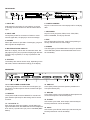
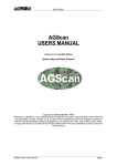
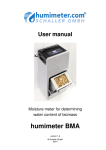
FRONTPANEL
MIC
INPUT
LINE
PHONES
DMM 4650 DIGITAL MESSAGE MANAGER
EXIT
1
2
3
4
5
7
6
8
POWER
9
6. CURSOR CURSOR
Keys to control the cursor in the display and for modifying
data.
1. INPUT MIC
XLR socket for connection of a microphone, to record
a message. Announcements can also be made via this
input.
7. RECORDER
Keys for TITLE jump back, REW, PLAY, STOP, REC,
FAST FORWARD, TITLE jump forward.
2. INPUT LINE
Cinch (RCA) socket for connection of stereo or mono
sources (tape deck, CD player) to record a message.
8. EXIT
Key for fast ending of the resp. mode. Each pressing of
the key switches back one menu stage.
3. PHONES
Stereo jack 6.3mm for pre-listen of messages, gong and
alarm signals via headphones.
9. POWER
The LED lights up if the DMM 4650 is ready for operation.
If the LED blinks please call a DYNACORD service center immediately.
4. MULTIFUNCTIONAL DISPLAY
Back-lit LC display, 2 lines with 16 characters each. Display lights up if any key is pressed. Display light switches
off if EXIT key is pressed, or no key is pressed for five
minutes.
5. SOFTKEY
The softkeys are used in various ways, depending on the
edit mode, and are indicated accordingly in the display.
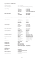
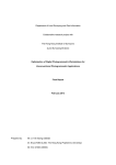
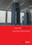
REARPANEL
DMM 4650
24V
+
-
5
1
REMOTE
10
11
14
MADE IN GERMANY
121675
1
6
9
SER.NO.
13
POR T A
12
25
1
14
13
POR T B
25
1
14
13
13
POR T C
14*
10. 24 V DC POWER CONNECTORS
2 flat-pin plugs 6,3mm for connection to emergency power supply or external power sources. Please note right
polarity (+)!
25
1
14
13
POR T D
15*
25
PRE-OUT
16
REC-INP
17
OUTPUT
18
INPUT
19
16. PRE-OUT
Cinch (RCA) socket, pre-listen (wired in parallel to the
front-panel stereo jack).
17. REC-INP
Cinch (RCA) socket, record (parallel but decoupled to the
cinch socket Input Line at the front panel).
11. REMOTE
The 9-pole D-SUB connector REMOTE is a serial computer interface (RS-232) for data saving and for service
functions.
18. OUTPUT
XLR socket 3-pole male, audio output, electronically balanced (transformer can be retrofitted).
12 - 15. PORT A - D
Each input and output is provided in 2-pole floating design and isolated from the DMM 4650 circuit and adjacent
lines. Port C (14) and Port D (15) can be retrofitted (NRS
90024).
19. INPUT
XLR socket 3-pole female, audio input, electronically balanced (transformer can be retrofitted).
20
Specifications DMM 4650
Operating Voltage
Power consumption
21.6 - 31.2V DC
max. 18 watts (without retrofitting kits 90204)
Input voltage
Input
*Line Input
*Rec Input
*Mic Input
0.775V/0dBu
0.775V/0dBu
0.775V/0dBu
1.4mV/ -54dBu at 600 ohms
Max. Input voltage
Input
3.8V/+14dBu
*Line INPUT
30V/+32dBu
*Rec INPUT
30V/+32dBu
*Mic INPUT
50mV/ -24dBu at 600 ohms
* If several of these inputs are used simultaneously, the stated voltages change.
Input impedance
Input(bal.)
Input (unbal.)
Line Input
REC Input
Mic INPUT
20kOhm
10kOhm
20kOhm
20kOhm
1,4kOhm
Output voltage
Output
Pre-Output
Phones
0.775V/0dBu
3.2V/+12dBu
3.2V/+12dBu
Max. Output voltage
Output
3.8V/+14dBu
Pre-Output
9V/+21dBu
Phones
9V/+21dBu
Output (bal.)
136 Ohm
Output (unbal.)
68 Ohm
Pre-Output
220 Ohm
Phones
220 Ohm
Input > Output
20Hz-20kHz -3/0dB
Mic Input
20Hz-16kHz -18/3dB
Others
20Hz-16kHz +0/-3dB
Input > Output
> 108dB (A-weighted)
Message
> 90dB (A-weighted)
Input > Output
< 0.03% (at 1kHz)
Message
< 0.05% (at 1kHz)
AD/DA converter
16 bit linear
DSP internal
24 bit
35kHz
Ein < ± 5V = Low
Ein > ±10V = High
floating relay contacts 1A at 24V DC
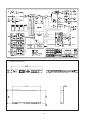
483 X 43.6 X 225 (W x H x D) 19in, 1HU
4kg
Output impedance
Frequency response
Signal-to-noise ratio
THD
Data format
Sampling rate
Control inputs
Control outputs
Dimensions
Weight
Retrofitting kits
Port C or D
Memory extension
Output transformer
NRS 90204
4 control inputs and outputs
NRS 90205
message memory extension
NRS 90210
21
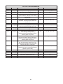
LIST FACTORY SEQUENCES
Sequence
Title
Description
Priority
Stopp trigger
S 20
“Stop all”
Stops all running sequences
99
off
S 21
“Alarmtxt”
Start alarm text (message 00) once
97
off
S 22
“DIN-ALrm”
Start continuous DIN alarm
(siren 1200 Hz - 500 Hz, 1 sec. Each)
93
off
S 23
“DIN-ALrm”
Start DIN alarm (key B1 ON), Stop with
key B1 OFF
95
B1 Low >00,1s stc
S 24
“Alrm-Txt”
DIN alarm > alarm text > DIN alarm
sequence, (start key B2 ON), Stop with
key B2 OFF
91
B2 Low >00,1s stc
S 25
“Vierklng”
4-tone gong
89
off
S 26
“Vorgong”
Start Pre-gong (key B4 on),
end of announcement with key B4 off
87
B4 Low >00,1s stc
S 27
“Message1“
Start Message 1
80
off
S 28
“Message2“
Start Message 2
80
off
S 29
“EasyRec1“
Start Recording Message 01
(remote recording), start by briefly pressing to input C3 (menu trigger), stop by
pressing again to input C3
80
C3 High >00,1s lat
S 30
“EasyRec2“
Start Recording Message 02
(remote recording), start by briefly pressing to input C4 (menu trigger), stop by
pressing again to input C4
80
C4 High >00,1s lat
S 31
“Fire-Mic”
Start continuous DIN alarm, pressing the
key “fire microphone” allows for an announcement via audio input, after releasing key the alarm is continued.
98
off
S 32
“Ansage”
Announcement via Recording input DMM
4650 as long as key is keeping pressed
(System input -20 dB).
80
D3 Low >00,1s stc
S 33
“BZB-ABC”
BZB-ABC alarm
95
off
S 34
“gen-emgc”
Ship alarm “General Emergency”
95
off
S 35
5“fireship”
Ship alarm “Fire”
95
off
S 36
“ManMorse”
Ship alarm “Manual Morse key”
95
off
S 37
“Telefon”
Telephone bell
95
off
22
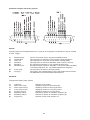
Installation example with factory presets:
INPUTS:
All input signals must be applied 200 msec. in order to be recognised. This default can only be modified
in menu “Trigger”.
A1
A2
A3
A4
B1
B2
Release signal:
General Stop:
Alarm text:
DIN alarm:
DIN alarm:
DIN alarm text:
B3
B4
4-tone gong:
Pre-gong:
Input for check-back signal: unit (power amplifiers) ready
Input (impulse) for interruption of all currently running sequences
Input (impulse) for previously recorded alarm message (M00)
Input (impulse) for continuous DIN alarm (siren 1200 Hz - 500 Hz).
Key pressed for DIN alarm on, key released finishes alarm
Key pressed starts sequence, DIN alarm, 1 sec break, alarm text (M00),
1 sec break, DIN alarm, etc., key released finishes this sequence.
Input (impulse) for starting 4-tone gong (G20).
Input (static), key pressed starts pre-gong and enables announcement
via DMM 4650, key released finishes this sequence.
OUTPUTS:
All outputs are floating relay contacts.
A1
A2
A3
A4
B1
B2
B3
B4
System on:
Alarm text running:
Alarm signal running:
4-tone gong running:
Pre-gong running:
Mandatory relay E:
Mandatory relay D:
Program off:
Switches on PA system.
Signalling contact for alarm text active.
Signalling contact for alarm signal active.
Signalling contact for 4-tone gong active.
Signalling contact for pre-gong active.
Switches PA system to mandatory reception (E).
Switches PA system to mandatory reception (D).
Switches current music program off.
23
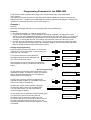
Programming Examples for the DMM 4650
Page numbers within brackets (Sxxx) refer to the corresponding page of the DMM 4650's
user's manual.
The following examples are based on the assumption that the appliance's mode is set as follows:
Software revision 1.1 (page 22), the DMM 4650 is in the factory-preset mode (page 27 and page 36),
operation is performed in the user level 3 status (page 10).
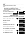
Example 1
Intention:
Recording a message that later on is to be played back using a external key.
Summary
1. Recording a message (i. e. M03) in speech quality.
2. To include the reproduction of this message in an existing installation, an appropriate control
sequence has to be established that gets a priority between "fire alert" and "gong" (i. e. priority 90).
This sequence also activates an optical signal in form of a lit lamp for the period of the outgoing
message. To accomplish the task, this example uses the relay contact 2 of the port A (=A2).
3. An input, which at the moment is unused (i. e. B.4) had been connected to the "Start"-key (page
30). This input has to be programmed in the "Auslöser" (trigger) menu for that pressing the start
button activates the above mentioned sequence (S03).
Step By Step Programming
Enter the password for the user level 3 on the display,
using the four cursor keys (page 10) and confirm your
action with the "ok"-button.
If you have entered the correct password,
the display briefly shows this message and
then returns to the main menu.
Ù
Ø
×
****
ok
Ú
Dynacord DMM4650
Userlevel 3
Main-Menu
System-Setup
Ù
After pressing this cursor key twice, the "Message"menu appears. Confirm your selection with the "ok"button.
Ø
×
Ú
2x
Recording a message
On the display the message number 00 and the name
"Message" is shown. The numeric values mm=minutes
and ss=seconds equal the time of a message that
already exists in the register 00.
ok
Main-Menu
Message
ok
M00’Message ‘ vl
mm:ss.s
edt
3x Ù
Pressing this cursor key three times displays the
required message register 03. The display shows the
name of the "empty" message 03.
Pressing the "record"-button displays a proposal
for the audio quality of the new recording (page
14). Using the soft key "ok" the proposition is
confirmed (speech quality).
password?
Ø
×
M03’
-empty
‘ vl
edt
Ú
I<< << >¨ O >> >>I
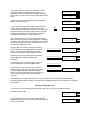
On the display you are asked for the level setting (page
14). Since this is your first recording with the
microphone, the level has to be set a new. The
microphone has to be connected to the MIC-socket on
the front panel and pressing the soft key "yes", the
automatic adjustment process for the electronic control
is activated.
record-mode
8kHz long
ok
select new
recordlevel?
y
n
You have to perform a short test, speaking into the
microphone with a normal talking level and in an
appropriate distance. Whenever the display changes
from "<min" to "norm" the mic level is within the relevant
range.
recordlevel
test
Using the soft key "ok" the setting is being stored and
stays in memory (page 14).
Pressing the button "start/stop" lets you control
your recording through the PHONES output.
If recording was not successful, you can give it
another try by pressing the "record" button. In this
case the display shows the message "delete?".
When you are sure that this is what you want, you
have to acknowledge the fact by pressing the
"yes" key.
recordlevel
test
norm
ok
test
EXIT
If the level was right ("norm" is shown on the display),
after pressing the "ok" key that the appliance is ready for
recording. The graphic bar in the lower line of the display
allows checking the input level. The Recorder is in the
pause-mode (ready to record).
Pressing the stop key terminates the recording
and the display shows the starting-menu
"message".
ok
recordlevel
In case the input level was too high and the indication
">max" has been displayed, you have to press the
"EXIT" button and follow the procedure once again from
the point where the record key was pressed. This time
the speaking distance to the microphone should be
increased; which results in a lower input level.
Pressing the record button starts the recording.
The recording time gets displayed in m=minutes
and ss, s= seconds and the graphic bar offers
continuous verification of the actual input level.
<min!
norm
ok
recordlevel
test
>max
ok
record M03
vl
paused I========
I<< << >¨ O >> >>I
record M03
vl
m:ss,s I========
I<< << >¨ O >> >>I
M03’Message ‘ vl
mm:ss.s
edt
I<< << >¨ O >> >>I
I<< << >¨ O >> >>I
M03’Message ‘
delete?
y
n
The message 03 is being erased and a you can proceed with a new recording (RECORD key).
Recording quality and level setting only have to be re-adjusted if they were the cause for re-recording
the message.
Naming The Message, Title
To provide the new recording (message) with a new name, you have to follow these steps:
Press the soft key "edit".
In the display appears the sub menu "Message edit".
Using the soft key "ok", the system is ready to accept the
entry of a new name.
M03’Message ‘ vl
mm:ss.s
edt
Message edit
title
ok
The name ("Message") with a maximum length of eight
characters can now be changed as desired. Using the
soft key "A-a" lets you choose between the upper and
the lower character set. By pressing the "spc" (space)
key you can enter spaces. The blinking cursor indicates
which character is going to be changed and using the
two "horizontal" cursor keys lets you select adjacent
characters.
The "vertical" cursor keys select the character that is
going to be entered at the cursor position. The example
shows the message 'Test 1.'.
Ù
Ø
×
Messg title
‘Message ‘
A-a
spc
Messg title
‘ essage ‘
A-a
spc
Messg title
‘ Test 1 ‘
A-a
spc
Ú
Ù
Ø
×
Ú
After you have entered the desired title, pressing the
"EXIT" key once displays the question "save?". Press the
soft key "yes" to store the selected name for the
Message 03 into memory.
M03’ Test 1 ‘
save?
EXIT
The display shows the starting menu for the message
programming.
y
n
M03’ Test 1 ‘ vl
mm:ss.s
edt
Pressing the "EXIT" button once lets you return to the
main menu.
EXIT
Main-Menu
Message
ok
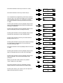
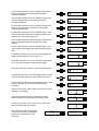
Programming A Control Sequence
Creating a procedure, the newly defined message has to be included into a sequence (page 23). In this
example the sequence-preset S 27 is chosen as the root-preset for further programming (page 39).
Press the "right" cursor key three times so that the
display reads as indicated. Using the soft key "ok" gets
you into the "Sequence" menu.
Ù
Ø
×
Ú
3x
Pressing the soft key "ok" once again shows a menu that
lets you select a sequence-preset.
A blinking "0" (cursor) is displayed in the lower line.
Press the "up" cursor until the reading shows "S 27".
Main-Menu
Sequence
ok
Sequence
load
ok
Ù
Ø
×
Sequ load
y
S20 ‘stop all’ n
Ú
To acknowledge your selection press the "yes" key.
Sequ load
y
S27 ‘Message1’ n
Since the procedure has to be changed in accordance to
the new requirements, you have to select its listing by
pressing the "ok" key.
Sequence
steplist
ok
steplist
1:OutC.1 set
d
i
Ø
steplist
1:OutC.1 set
d
i
Ø
steplist
1:OutA.1 set
d
i
The first step (step 1) of the S 27 listing is displayed.
Here, you have to change the relay output (indicator
lamp) from port C relay 1 to port A relays 2.
Press the indicated cursor key twice to have the "C"
blink.
Ù
×
Ú
2x
2x Ù
Press the indicated cursor key twice to select port A.
×
Ú
Ù
Press the indicated cursor key to have the "1" blink.
×
Ø
steplist
1:OutA.1 set
d
i
Ø
steplist
1:OutA.2 set
d
i
Ø
steplist
1:OutA.2 set
d
i
Ø
steplist
2:Sum=off
d
i
Ø
steplist
3:DMM= -2dB
d
i
Ø
steplist
4:Start M01
d
i
Ø
steplist
4:Start M01
d
i
Ø
steplist
4:Start M03
d
i
Ø
steplist
4:Start M03
d
i
Ø
steplist
5:wt Audio
d
i
Ø
steplist
6:End
d
i
Sequ save
to S27
y
n
Sequ save
to S03
y
n
Sequ save
to S03
y
n
Ú
Ù
Press the indicated cursor key to select relay 2.
×
Ú
This completes the programming of the relay contact 2
of port A (set). The result is the lighting of an externally
connected lamp whenever your sequence is started.
Press the indicated cursor key three times to have the
"1" blink.
Pressing the indicated cursor key displays step 2 which
stays unchanged (disables the master input during the
message is outputted).
Pressing the indicated cursor key displays step 3 which
stays unchanged (sets the message's volume).
Ù
×
Ú
3x
Ù
×
Ú
Ù
×
Ú
Pressing the indicated cursor key displays step 4 which
activates the reproduction of the message "M01".
Ù
×
Ú
Pressing the indicated cursor key four times sets the
blinking cursor to the "1".
Ù
×
Ú
Pressing the indicated cursor key twice selects message
03. This starts the reproduction of your previously
recorded message "M03".
Press the indicated cursor key displays twice to have the
"4" blink.
2x Ù
×
Ú
Ù
×
Ú
Pressing the indicated cursor key displays step 5 which
stays unchanged (wait for the end of the message).
4x
2x
Ù
×
Ú
Pressing the indicated cursor key displays step 6 which
stays unchanged. This is also the last step of the
procedure.
Ù
×
Ú
When you press the "EXIT" button, the question
"save?" appears on the display.
Press the indicated cursor key repeatedly until the
display reads the required sequence number (S03).
EXIT
Ù
Ø
×
Ú
Pressing the soft key "yes" stores your new sequencelisting as preset S03 into memory.
After showing a short message that
storing was successful, the display
returns to the start-screen of the
sequence.
Sequence
Sequence
steplist
saved
ok
Naming The Sequence, Title
In case you want to give the new sequence its own name, you have to follow this procedure:
Pressing the indicated cursor key enters the title-menu.
Pressing the soft key "ok" prepares the system for the
entry of a new name.
Ù
Ø
×
Sequence
title
ok
Ú
The following programming steps – entering and saving the desired name - are equivalent to the above
description of how to enter and store the "title of a message" (page 24).
Priority Of The Sequence
The priority of the new sequence S03 has to be set to a value of 90. Thus, follow these steps:
The priority-menu is entered by pressing the indicated
cursor key three times and pressing the "ok" key
prepares the system for the entering of a new priority
value.
Ù
Ø
×
Ú
3x
The display shows the programmed priority of the
sequence S27.
Sequence
priority
ok
Sequ priority
80
Press the indicated cursor key until the required value of
"90" is displayed.
Ù
Ø
×
Sequ priority
90
Ú
Pressing the "EXIT" button displays the question
"save?". Use the soft key "yes" to save the priority
for the sequence S03.
After showing a short message that the
storing was successful, the display
returns to the priority-screen of the
sequence.
Sequ save
to S03
EXIT
Sequence
saved
Pressing the "EXIT" key once lets you return to the main
menu. This concludes the programming of your new
procedure.
Sequence
priority
y
n
ok
Main-Menu
EXIT
Sequence
ok
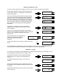
Setting The Trigger
You want your new sequence to be triggered by pressing the desired button on port B input 4. Thus,
the programming is performed in the "trigger" menu.
Pressing the indicated cursor key enters the trigger
menu. Press the "ok" button to acknowledge your
selection.
Ù
Ø
×
Trigger
ok
Ú
The display shows that the input 1 of the port A is
disabled.
Pressing the indicated cursor key selects the port B. In
the bottom line of the display, the setting for port B, input
1 is shown.
Main-Menu
starttrg A.1 set
off
Ù
Ø
×
Ú
starttrg B.1 set
H >00,1s dyn S23
Pressing the indicated key sets the cursor to the number
mark of the input.
Ù
×
Ø
starttrg B.1 set
H >00,1s dyn S23
Ø
starttrg B.4 set
H >00,1s dyn S26
Ø
starttrg B.4 set
H >00,1s dyn S26
Ø
starttrg B.4 set
H >00,1s dyn S03
Ú
Select the input 4 by pressing the indicated cursor key.
The bottom line of the display shows the momentary
setting for the port B, input 4, which would start the
sequence 26.
Programming the start of the sequence 03 you have to
press the indicated key twice to set the blinking cursor to
"6".
Press the indicated cursor key repeatedly until the
display shows the desired number of the sequence
(S03). Pressing the soft key "set" stores your setting into
memory.
Ù
×
Ú
2x Ù
×
Ú
Ù
×
Ú
From now on, pressing the external button at the input B4 activates the sequence 03.
Pressing the "EXIT" key twice ceases the programming.
The display is dimmed and you are able to test the
functioning of the sequence (example 1).
EXIT
2x
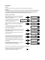
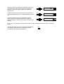
Example 2
Intention:
You want to activate a factory preset alert using another key than pre-programmed.
Summary
Employing a previously unused input (e. g. B3) you want to trigger included DIN-alert of the DMM 4650.
The functioning of the input A4 which is already utilized for the DIN-alert has to be maintained. The
new, additional start-key has been already connected to the port B, input 3 (page 30). It has to be
programmed in the trigger menu to activate the sequence "DIN-Alarm" (=S22).
Step By Step Programming
Enter the password for the user level 3 on the display,
using the four cursor keys (page 10) and confirm your
action with the "ok"-button.
If you have entered the correct password,
the display briefly shows this message and
then returns to the main menu.
Ù
Ø
×
Main-Menu
2x Ù
Ø
×
Pressing the indicated key positions the cursor on the
number of the input.
System-Setup
ok
Main-Menu
Trigger
ok
Ú
The display shows that input 1 of port A is disabled.
You can always change the character on which the
blinking cursor is positioned.
Pressing the indicated key positions the cursor on "Port
B". The bottom line in the display shows the momentary
setting of port B, input 1.
ok
Ú
Dynacord DMM4650
Userlevel 3
After pressing this cursor key twice, the "Trigger" menu
appears. Confirm your selection by pressing the "ok"button.
password?
****
starttrg A.1 set
off
Ù
×
Ø
starttrg B.1 set
H >00,1s dyn S23
Ø
starttrg B.1 set
H >00,1s dyn S23
Ø
starttrg B.3 set
H >00,1s dyn S25
Ø
starttrg B.3 set
H >00,1s dyn S25
Ø
starttrg B.3 set
H >00,1s dyn S22
Ú
Ù
×
Ú
Pressing the indicated cursor key twice selects input 3.
The bottom line in the display shows the momentary
setting of port B, input 3 which triggers sequence 25.
2x Ù
×
Ú
2x Ù
To start the required alarm-sequence 22, you have to
press the indicated cursor key twice so that "5" appears
in the display.
×
Pressing the indicated cursor key three times displays
the required sequence number (S22).
Press the soft key "set" to store the setting.
×
Ú
Ù
Ú
3x
From now on, the external button of the input B3 triggers the sequence 22.
Pressing the "EXIT" key twice ceases the programming.
The display is dimmed and you are able to test the
functioning of the sequence (example 2).
EXIT
2x
Example 3
Intention:
You want to trigger the pre-programmed 3-tone gong signal (factory-preset G21) by an external key.
The functioning of the 4-tone gong signal has to be maintained.
Summary
1. To include the reproduction of the 3-tone gong signal in the existing configuration, you have to
program a suitable control sequence (e. g. S05). The sequence is also about to trigger an external
control-lamp for the time, the gong signal gets reproduced. This example utilizes the identical relay
contact 4 of the port A (=A4) that is already in use for the 4-tone signal.
2. The unused input of the pre-gong signal (e.g. B4) has been connected to the start-key (page 30). It
has to be programmed in the trigger menu to activate the above sequence (S05).
Step By Step Programming
Enter the password for the user level 3 on the display,
using the four cursor keys (page 10) and confirm your
action with the "ok"-button.
If you have entered the correct password,
the display briefly shows this message and
then returns to the main menu.
Ù
Ø
×
password?
****
ok
Ú
Dynacord DMM4650
Userlevel 3
Main-Menu
System-Setup
ok
Programming The Control Sequence
Creating a procedure, the 3-tone gong signal G21 has to be included into a sequence (page 23). The
sequence-preset S 25 is chosen as the root-preset for further programming (page 39).
After pressing the indicated cursor key five times, the
sequence menu appears on the display. Confirm your
selection by pressing the "ok"-button.
Ù
Ø
×
Ú
5x
Pressing the soft key "ok" once again shows a menu that
lets you select a sequence-preset.
The blinking cursor is positioned at the "0" in the
display's bottom line.
Press the indicated cursor key repeatedly until "S 25" is
selected. Press the soft key "yes" to load the sequence
preset S 25 (root-sequence).
Main-Menu
Sequence
ok
Sequence
load
ok
Sequ load
y
S20 ‘stop all’ n
5x Ù
×
Ø
Sequ load
y
S25 ‘Vierklng’ n
Ú
Since the procedure has to be changed in accordance to
the new requirements, you have to select its listing by
pressing the "ok" key.
Sequence
steplist
ok
The first step (step 1) of the S 25 listing is displayed,
which stays unchanged (relay contact A1 can be utilized
to turn the system's power on).
steplist
1:OutA.1 set
d
i
Ø
steplist
2:wt InA.1 H
d
i
Ø
steplist
3:OutB.4 clr
d
i
Pressing the indicated cursor key displays step 2 which
stays unchanged (release-input A1 of the electro
acoustic system ready?).
Pressing the indicated cursor key displays step 3 which
stays unchanged (relay contact B4 for music off).
Ù
×
Ú
Ù
×
Ú
Pressing the indicated cursor key displays step 4 which
stays unchanged (relay contact B2 for obligatory
reception activated).
Ù
×
d
Ø
steplist
5:OutB.3 set
d
Ø
steplist
6:OutA.4 set
d
i
Ø
steplist
7:Sum=off
d
i
Ø
steplist
8:DMM= -2dB
d
i
Ø
steplist
9:Start G20
d
i
Ø
steplist
9:Start G20
d
i
Ø
steplist
9:Start G21
d
i
Ø
steplist
9:Start G21
d
i
Ø
steplist
10:wt Audio
d
i
Ø
steplist
11:End
d
i
Sequ save
to S25
y
n
Sequ save
to S05
y
n
Sequ save
to S05
y
n
Ù
×
Pressing the indicated cursor key displays step 6 which
stays unchanged (relay contact A4 for control lamp
"outgoing gong signal).
×
i
i
Ú
Ù
Ú
Ù
Pressing the indicated cursor key displays step 7 which
stays unchanged (switches the master input during the
reproduction of the gong signals off).
×
Pressing the indicated cursor key displays step 8 which
stays unchanged (setting the volume of the gong
signals).
×
Pressing the indicated cursor key displays step 9. This
step normally would trigger the start of the gong signal
G20.
×
Ú
Ù
Ú
Ù
Ú
Ù
×
Ú
Press the indicated cursor key to select the gong signal
G21. This step activates the desired gong signal.
steplist
4:OutB.2 set
Ú
Pressing the indicated cursor key displays step 5 which
stays unchanged (relay contact B3 for obligatory
reception activated).
Press the indicated key four times to set the displayed
value under the blinking cursor mark to "0".
Ø
4x
Ù
×
Ú
Ù
Press the indicated key twice to have the value "9" blink.
×
Ú
Pressing the indicated cursor key displays step 10 which
stays unchanged (wait for the gong signal to fade out).
2x
Ù
×
Ú
Pressing the indicated cursor key displays step 11 which
stays unchanged. This is also the last step of the
procedure.
Ù
×
Ú
When you press the "EXIT" button, the question "save?"
appears on the display.
EXIT
Ù
Press the indicated cursor key repeatedly until the
display reads the required sequence number (S05).
Ø
×
Ú
Pressing the soft key "yes" stores your new sequencelisting as preset S05 into memory.
After showing a short message that
storing was successful, the display
returns to the start-screen of the
sequence.
Sequence
saved
Sequence
steplist
ok
Naming The Sequence, Title
In case you want to give the new sequence its own name, you have to follow this procedure:
Pressing the indicated cursor key enters the title-menu.
Pressing the soft key "ok" prepares the system for the
entry of a new name.
The name ("Vierklng") with a maximum length of eight
characters can now be changed as desired. Using the
soft key "A-a" lets you choose between the upper and
the lower character set. By pressing the "spc" (space)
key you can enter spaces. The blinking cursor indicates
which character is going to be changed and using the
two "horizontal" cursor keys lets you select adjacent
characters.
Ù
Sequence
title
ok
Ú
Ù
Ø
×
Sequ title
‘Vierklng’
A-a
spc
Sequ title
‘Drerklng’
A-a
spc
Sequ title
‘Dreiklng’
A-a
spc
Ú
Ù
Using the two "vertical" cursor keys, the desired
characters can be selected. This example uses the
name "Dreiklng".
Ø
×
Ú
After you have entered the desired title, pressing the
"EXIT" key once displays the question "save?". Press the
soft key "yes" to save the selected name for the
sequence 05.
After showing a short message that the
storing was successful, the display
returns to the title-screen of the
sequence.
Ø
×
Sequ save
to S05
EXIT
Sequence
saved
Pressing the "EXIT" key once lets you return to the main
menu.
EXIT
y
n
Sequence
title
ok
Main-Menu
Sequence
ok
This concludes the programming of your new procedure. The priority level of the sequence has not
been altered and is therefore equivalent to the setting of S 25 (4-tone gong signal).
Setting The Trigger
You want your new sequence to be triggered by pressing the desired button on port B input 4. Thus,
the programming is performed in the "Trigger" menu.
Pressing the indicated cursor key enters the trigger
menu. Press the "ok" button to acknowledge your
selection.
Ù
Ø
×
Pressing the indicated key sets the cursor to the number
mark of the input.
ok
Ú
The display shows that the input 1 of the port A is
disabled.
Pressing the indicated cursor key selects the port B. In
the bottom line of the display, the setting for port B, input
1 is shown.
Main-Menu
Trigger
starttrg A.1 set
off
Ù
×
Ø
starttrg B.1 set
H >00,1s dyn S23
Ø
starttrg B.1 set
H >00,1s dyn S23
Ú
Ù
×
Ú
Select the input 4 by pressing the indicated cursor key.
The bottom line of the display shows the momentary
setting for the port B, input 4, which would start the
sequence 26.
Programming the start of the sequence 05 you have to
press the indicated key twice to set the blinking cursor to
"6".
Press the indicated cursor key repeatedly until the
display shows the desired number of the sequence
(S05). Pressing the soft key "set" stores your setting into
memory.
Ù
×
Ø
starttrg B.4 set
H >00,1s dyn S26
Ø
starttrg B.4 set
H >00,1s dyn S26
Ø
starttrg B.4 set
H >00,1s dyn S05
Ú
2x Ù
×
Ú
Ù
×
Ú
From now on, pressing the external button at the input B4 activates the sequence 05 (=3-tone gong
signal).
Pressing the "EXIT" key twice ceases the programming.
The display is dimmed and you are able to test the
functioning of the sequence (example 3).
EXIT
2x
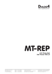
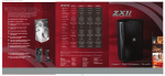
Abmessungen/Dimensions
35
Bosch Communications Systems
Americas–Headquarter Americas
Telex Communications, Inc.
12000 Portland Ave South,
Burnsville, MN 55337, USA
USA–Ph: 1-800-392-3497
Fax: 1-800-955-6831
Canada–Ph: 1-866-505-5551
Fax: 1-866-336-8467
Latin America–Ph: 1-952-887-5532
Fax: 1-952-736-4212
Europe, Africa & Middle-East
Headquarter EAME
EVI Audio GmbH
Hirschberger Ring 45, D-94315,
Straubing, Germany
Phone: +49 9421 706-0,
Fax: +49 9421 706-265
Asia & Pacific Rim–Headquarter Asia
Singapore: Telex Pte. Ltd.
3015A Ubi Road 1
05-10 Kampong Ubi Industrial Estade
Singapore 408705
Phone: +(65) 6746-8760
Fax: +(65) 6746-1206
Japan: EVI Audio Japan Ltd.
5-3-8 Funabashi, Setagaya-Ku,
Tokyo, Japan 156-0055
Phone: +81 3-5316-5020,
Fax: +81 3-5316-5031
Hong Kong: Telex EVI Audio (HK) Ltd.
Unit 5,1/F, Topsail Plaza
11 On Shum Street
Shek Mun,Shatin HK
Phone: +852 2351-3628,
Fax: +852 2351-3329
China: Telex EVI Audio (Shanghai) Ltd.
Room 2210-2215, Tower B
Far East International Plaza
No. 317, Xianxia Road,
Shanghai, China.
Postal Code: 200051
Phone: +86 21-6235-1677
EVI AUDIO GmbH
www.eviaudio.com
Subject to change without prior notice.
Printed in Germany
07 /10 /2008 / D355 606