1
VideoEdge Appliance Installation
and User Guide
VideoEdge 4.5
8200-1055-01 A0
1
Notice
The information in this manual was current when published. The manufacturer reserves the right to revise and improve
its products. All specifications are therefore subject to change without notice.
Product offerings and specifications are subject to change without notice. Not all products include all features; refer to
product datasheets for full feature information.
Copyright
Under copyright laws, the contents of this manual may not be copied, photocopied, reproduced, translated or reduced
to any electronic medium or machine-readable form, in whole or in part, without prior written consent of Tyco Security
Products.
© 2014 Tyco Security Products. All Rights Reserved.
American Dynamics
60 Congress Avenue
Boca Raton, FL 33487 U.S.A.
Customer Service
Thanks you for using American Dynamics products. We support our products through an extensive worldwide network
of dealers. the dealer through whom you originally purchased this product is your point of contact if you need service or
support. Our dealers are empowred to provide the very best in customer service and support. Dealers should contact
American Dynamics at (800) 507-6268 or (561) 912-6259 or on the Web at www.americandynamics.net.
Trademarks
Windows® is a registered trademark of Microsoft Corporation. PS/2® is a registered trademark of International
Business Machines Corporation.
The trademarks, logos, and service marks displayed on this document are registered in the United States [or other
countries]. Any misuse of the trademarks is strictly prohibited and Tyco International Ltd. will aggressively enforce its
intellectual property rights to the fullest extent of the law, including pursuit of criminal prosecution wherever
necessary. All trademarks not owned by Tyco International Ltd. are the property of their respective owners, and are
used with permission or allowed under applicable laws.
Product offerings and specifications are subject to change without notice. Actual products may vary from photos. Not
all products include all features. Availability varies by region; contact your sales representative.
MPEG-4 Disclaimer
This product is licensed under the MPEG-4 Visual Patent Portfolio License for the personal and non-commercial use of
a consumer to (i) encoding video in compliance with the MPEG-4 visual standard (“MPEG-4 Video”) and/or (ii)
decoding MPEG-4 video that was encoded by a consumer engaged in a personal and non-commercial activity and/or
was obtained from a video provider licensed by MPEG LA to provide MPEG-4 video. No license is granted or shall be
implied for any other use. Additional information including that relating to promotional, internal and commercial uses
and licensing may be obtained from MPEG LA, LLC. See HTTP://WWW.MPEGLA.COM
H.264 Disclaimer
This product is licensed under the AVC Patent Portfolio License for the personal and non-commercial use of a
consumer to (i) encode video in compliance with the AVC Standard (“AVC Video”) and/or (ii) decode AVC video that
2
was encoded by a consumer engaged in a personal and non-commercial activity and/or was obtained from a video
provider licensed to provide AVC video. No license is granted or shall be implied for any other use. Additional
information may be obtained from MPEG LA, LLC. See HTTP://WWW.MPEGLA.COM
License Information
Your use of this product is governed by certain terms and conditions. Please see the detailed license information at the
end of this manual.
United States
FCC Compliance
This equipment has been tested and found to comply with the limits for a Class A digital device, pursuant to part 15 of
the FCC Rules. These limits are designed to provide reasonable protection against harmful interference when the
equipment is operated in a commercial environment. This equipment generates, uses, and can radiate radio frequency
energy and, if not installed and used in accordance with the instruction manual, may cause harmful interference to
radio communications. Operation of this equipment in a residential area is likely to cause harmful interference in which
case the user will be required to correct the interference at his own expense.
Changes or modifications not expressly approved by Sensormatic, could void the user’s authority to operate the
equipment.
This product was FCC verified under test conditions that included the use of shielded I/O cables and connectors
between system components. To be in compliance with FCC regulations, the user must use shielded cables and
connectors for all except power and alarm cables.
Canada
This Class A digital apparatus complies with Canadian ICES-003.
European Union
EMC compliance
Warning
This is a class A product. In a domestic environment this product may cause radio interference in which case the user
may be required to take adequate measures.
Only the following connections are expected to be limited to <3m cables:
USB
Only The following cables are expected to be shielded:
Video BNC cables
Monitor video cables
General Safety warnings
1
This product must be earthed. Plugs and sockets can vary between countries, ensure that the earth pin
mates correctly with the socket and that an earthed socket is used.
2
For indoor use only
3
For professional installation, use and service.
3
4
This product is only suitable for operation below altitudes or equivalent air pressure of:
• Desktop versions - 2000m
• Rack mountable versions - 3200m
For rack mountable equipment:
a
Elevated Operating Ambient - If installed in a closed or multi-unit rack assembly, the operating ambient
temperature of the rack environment may be greater than room ambient. Therefore, consideration should
be given to installing the equipment in an environment compatible with the maximum ambient temperature (Tma) of 35°C.
b
Reduced Air Flow - Installation of the equipment in a rack should be such that the amount of air flow
required for safe operation of the equipment is not compromised.
c
Mechanical Loading - Mounting of the equipment in the rack should be such that a hazardous condition is
not achieved due to uneven mechanical loading.
d
Circuit Overloading - Consideration should be given to the connection of the equipment to the supply circuit and the effect that overloading of the circuits might have on overcurrent protection and supply wiring.
Appropriate consideration of equipment nameplate ratings should be used when addressing this concern.
e
Reliable Earthing - Reliable earthing of rack-mounted equipment should be maintained. Particular attention should be given to supply connections other than direct connections to the branch circuit (e.g. use of
power strips).
This symbol means the product is classified as waste Electrical and Electronic equipment under the WEEE directive
(2002/96/EC). It should not be placed in the normal waste stream and should be separately collected for specific
recycling as WEEE.
The above symbol also covers the battery directive (2006/66/EC). The product contains a replaceable battery which
should not be placed in the normal waste stream and should be separately collected for specific recycling as waste
batteries.
Please check with your regional waste management authority on where to dispose of WEEE or Batteries or
packaging.
This device is not intended for use in the direct field of view at visual display workplaces. To avoid incommoding
reflections at visual display workplaces this device must not be placed in the direct field of view.
The power rating for desktop units is 100-240V, 50-60Hz, Max 300W, Max 4.5A. The power rating for the 2U and 3U
rack mountable units is 100-240V, 50-60Hz, Max 350W, Max 6.0A.
US/CAN deviations - The RJ45 connections
identified on the product as ‘RJ45 Gigabit Ethernet Port’ are
intended for ethernet use only, NOT for telecommunication applications.
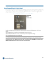
RTC Battery replacement
The product is fitted with an lithium metal coin-cell type CR2032, the user can replace this however a professionally
trained technician is recommended to avoid damage to the internals of the product.
A coin-cell battery (CR2032) powers the real-time clock and CMOS memory. When the product is not plugged into a
wall socket, the battery has an estimated life of three years. When the product is plugged in, the standby current from
4
the power supply extends the life of the battery. The clock is accurate to ± 13 minutes/year at 25°C with 3.3 VSB
applied.
When the voltage drops below a certain level, the BIOS Setup program settings stored in CMOS RAM (for example,
the date and time) might not be accurate. Replace the battery with an equivalent one.
Caution
RISK OF EXPLOSION IF BATTERY IS REPLACED BY AN INCORRECT TYPE.
DISPOSE OF USED BATTERIES ACCORDING TO THE INSTRUCTIONS.
To replace the battery, follow these steps:
1. Observe the following precautions:
• Disconnect the power before removing the cover. Note that there are hazardous
voltages in the PSU module, and while these cannot be touched easily and are protected it may be possible to touch live parts with a small tool.
• Take adequate ESD precautions and wear an ESD strap connected to the chassis of
the products.
• Preferably use a non-conductive tool to remove the battery, try to avoid touching the
new battery with fingers.
2. Turn off all peripheral devices connected to the computer. Disconnect the computer’s power cord from the AC
power source (wall outlet or power adapter).
3. Remove the computer cover.
4. Locate the battery on the board.
5. With a medium flat-bladed screwdriver, gently pry the battery free from its connector. Note the orientation of the “+”
and “-” on the battery.
6. Install the new battery in the connector, orientating the “+” and “-” correctly.
7. Replace the computer cover.
5
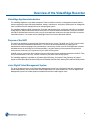
Overview of the VideoEdge Recorder
VideoEdge ApplianceIntroduction
The VideoEdge Appliance is a scalable enterprise IP video surveillance solution. It is designed as an open platform
solution supporting a range of third party hardware, storage, video devices, and clients, allowing users to manage their
video surveillance servers and edge devices as a single logical system.
The VideoEdge Appliance (NVR) manages the IP encoder and camera devices, records the video onto its configured
storage devices, and provides clients with secure access to live and recorded video and audio. Users can use a thinclient (NVR Administration Interface) or the victor rich-client application software to configure the NVR or access the
video/audio streams. You can also use the VideoEdge Client to access the video/audio streams.
Purpose of the NVR
The NVR is the backbone for an analog and IP-based video security system. The NVR uses TCP/IP communication
to access and control the hardware networked to it. The server can be controlled directly by logging into its
Administration interface homepage using a web browser or accessing it via the victor rich-client application software.
Worldwide access to the NVR gives it excellent portability - any place where you have a personal computer with
internet access to the web, you’ve got access to your video security system.
An NVR gives you control over all the features of the surveillance and security hardware networked to the NVR. Thus,
from your web browser or via victor, you have control over your entire video security system.
The VideoEdge Appliance is available in 16-Channel Hybrid Desktop, 32 Channel IP Only Desktop, 32 Channel
Hybrid 2U Rack Mount (RAID and Non-RAID) and 64-Channel Hybrid 3U Rack Mount (RAID and Non-RAID) models.
victor Digital Video Management System
The “open” architecture of the victor Digital Video Management System line is designed so that each component can
operate independently, and can interact with software applications from other product lines. The victor Digital Video
Management System line includes products to address the needs of a wide range of users.
6
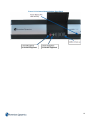
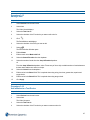
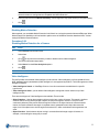
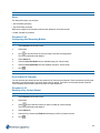
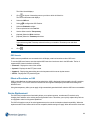
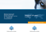
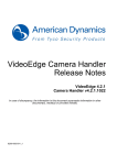
Figure 1-1 VideoEdge Network Video Components
The NVR manages the video camera, storage, and sensor assets for your site.
You use the NVR Administration Interface to configure and manage the NVR via a web browser. You can use these
web pages to configure the NVR and its storage, cameras, and devices. Typically, the assets connected to the NVR
are configured on a local TCP/IP network, isolated from the larger network, and accessible to clients via the NVR and
the victor site manager.
The victor site manager provides a single point of access for users to manage multiple NVRs. The victor site manager
utilizes SQL Server’s database functionality to provide authentication for VideoEdge Clients, as well as central
monitoring and administration of multiple recording platforms over a Wide Area Network (WAN). Refer to the victor
Configuration and User Guide for more information on configuring and using the victor site manager software. The
victor clients are used to monitor and configure one or more NVRs or other devices that are connected to the victor site
manager network. The victor client enables a user to login and access multiple NVRs from a single Graphical User
Interface (GUI). Refer to the victor Configuration and User Guide for more information on using the victor client
software.
7
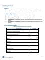
Installing Hardware
Overview
Prior to using your NVR for the first time, it is important that it has been connected with it's ancillaries correctly. The
following section details the hardware configuration for the different models of VideoEdge Appliances.
Hardware Configurations
The VideoEdge Hybrid NVR is available in several different configurations, they are as follows:
1
16 Channel Hybrid Desktop - This model provides 8 analog and 8 IP video channels.
2
32 Channel IP Only Desktop - This model provides 32 IP video channels.
3
32 Channel Hybrid 2U Rack Mount - This model is rack mountable and provides 16 analog and 16 IP video
channels.
4
64 Channel Hybrid, 3U Rack Mount - This model is rack mountable and provides 32 analog and 32 IP video
channels.
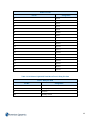
16 Channel Hybrid Desktop
Table 1-1 16 Channel Hybrid Desktop Configuration
Connector Type
Quantity
USB 2.0 Ports
6
3.5mm Microphone Socket (Not Supported)
2
3.5mm Headphone Socket (Not Supported)
1
3.5mm Line In Socket (Not Supported)
1
3.5mm Speaker Out Socket
1
USB 3.0 Ports
2
PS/2 Ports
1
6-Way Audio I/O
1
Parallel Ports
1
VGA Ports
1
DVI-I Ports
1
RJ45 Gigabit Ethernet Ports
2
BNC Video Inputs
8
BNC Monitor Outputs
1
Audio Inputs
8
Alarm Inputs
8
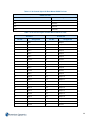
8
Connector Type
Quantity
Alarm Outputs (Not Supported)
8
Form C Relay Output
1
Serial Ports
1
RS422 Ports
1
9
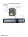
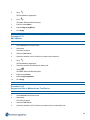
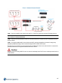
Figure 1-2 16 Channel Hybrid Desktop Front Panel
10
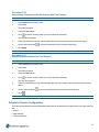
Figure 1-3 16 Channel Hybrid Desktop Rear Panel
32 Channel IP Only Desktop
Table 1-2 32 Channel IP Only Desktop Configuration
Connector Type
Quantity
USB 2.0 Ports
6
3.5mm Microphone Socket (Not Supported)
2
3.5mm Headphone Socket (Not Supported)
1
3.5mm Line In Socket (Not Supported)
1
3.5mm Speaker Out Socket
1
USB 3.0 Ports
2
PS/2 Ports
1
6-Way Audio I/O
1
Parallel Ports
1
VGA Ports
1
DVI-I Ports
1
RJ45 Gigabit Ethernet Ports
2
11
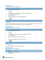
Figure 1-4 32 Channel IP Only Desktop Front Panel
12
Figure 1-5 32 Channel IP Only Desktop Rear Panel
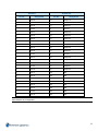
32 Channel Hybrid 2U Rack Mount
Table 1-3 32 Channel Hybrid 2U Rack Mount Configuration
Connector Type
Quantity
USB 2.0 Ports
6
3.5mm Microphone Socket (Not Supported)
1
3.5mm Line In Socket (Not Supported)
1
3.5mm Speaker Out Socket
1
USB 3.0 Ports
2
eSATA Ports
1
PS/2 Ports
1
6-Way Audio I/O
1
DVI-I Ports
1
HDMI Ports
1
Display Ports
1
RJ45 Gigabit Ethernet Ports
2
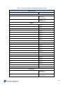
13
Connector Type
Quantity
BNC Video Inputs
16
BNC Video Through Loop Connectors
16
BNC Monitor Outputs
2
Audio Inputs
16
Alarm Inputs
16
Alarm Outputs (Not Supported)
16
Form C Relay Output
1
Serial Ports 2
2
RS422 Ports 1
1
14
Figure 1-6 32 Channel Hybrid 2U Rack Mount Front Panel
15
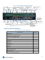
Figure 1-7 32 Channel Hybrid 2U Rack Mount Rear Panel
64 Channel Hybrid 3U Rack Mount
Figure 1-8 64 Channel Hybrid 3U Rack Mount
Connector Type
Quantity
USB 2.0 Ports 6
6
3.5mm Microphone Socket (Not Supported) 1
1
3.5mm Line In Socket (Not Supported) 1
1
3.5mm Speaker Out Socket 1
1
USB 3.0 Ports 2
2
eSATA Ports 1
1
PS/2 Ports 1
1
6-Way Audio I/O 1
1
DVI-I Ports 1
1
HDMI Ports 1
1
Display Ports 1
1
RJ45 Gigabit Ethernet Ports 2
2
BNC Video Inputs 32
32
BNC Video Loop Through Connectors 32
32
16
Connector Type
Quantity
BNC Monitor Outputs 2
2
Audio Inputs 32
32
Alarm Inputs 36
36
Alarm Outputs (Not Supported) 32
32
Form C Relay Output 2
2
Serial Ports 2
2
RS422 Ports 1
1
17
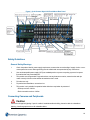
Figure 1-9 64 Channel Hybrid, 3U Rack Mount Front Panel
18
Figure 1-10 64 Channel Hybrid 3U Rack Mount Rear Panel
Safety Guidelines
General Safety Warnings
1
Check the product label for power supply requirements to assure that no overloading of supply circuits or overcurrent protection occurs. Mains grounding must be reliable and uncompromised by any connections.
2
Use an uninterruptible power supply (UPS) as standard practice to protect computing systems from power
fluctuations that may cause data loss.
3
This product must be grounded. Plugs and sockets can vary between countries, ensure that the earth pin
mates correctly with the socket and that an earthed socket is used.
4
For indoor use only
5
For professional installation, use and service.
6
This product is only suitable for operation below altitudes or equivalent air pressure of:
• Desktop versions - 2000m
• Rack mountable versions - 3200m
Connecting Cameras and Peripherals
Caution
Protect the unit against lightning. If part of a cable is installed outside a building, the entire cable is vulnerable to
lightning. Install surge protectors on all vulnerable cables.
19
Video Devices
Procedure 1-1
Connecting Video Devices
Step
Action
1
Connect the cameras:
a
Connect the video cables from the cameras to the BNC connectors labelled video inputs on the rear of
the unit.
2
Connect any External Storage Modules (ESMs).
3
Connect a monitor using either the VGA, DVI-I or HDMI ports.
Note:
VGA is only available on the 8 Channel Analog and 32 Channel IP Only Desktop variants.
4
(Optional) Connect a spot monitor to the video output BNC connector on the Analog board to see live video.
The 16 and 32 Channel Analog models have two video outputs. Video displayed from the video output is
configured using the Monitor Outputs page of the NVR Administrator interface, refer to Monitor Outputs for
further information.
- End -
Connecting Optional Components
You can connect optional devices to your NVR including:
1
A keyboard and mouse. Adding a keyboard to the NVR unit provides access to the operating system’s features such as Log Off, Shut Down and to other applications.
2
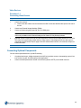
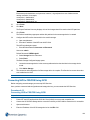
A dome controller (Sensormatic VM16E or American Dynamics ADTTE) to the COM2 connector.
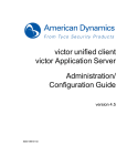
20
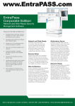
Figure 1-11 ADTTE Wiring Diagram
3
A matrix switcher for dome control or devices for serial text input through the USB port.
Connecting Alarms to the NVR
The alarm connectors on the back of the unit accept both alarm inputs and outputs. The alarm outputs are TTL outputs
5V DC, 20mA maximum.
The polarity of all alarm inputs is programmable. However, the polarity of all alarm outputs is active–high. Alarm
outputs are initialized to inactive–low on power-up.
Attach the alarm inputs, outputs, and grounds to the connectors, according to the pin assignment.
Connector Pin Outs
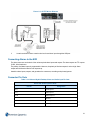
Table 1-4 16 Channel Hybrid Desktop Alarm and Audio Input Pin Outs
Alarm and Audio Input Pin Outs
Pin No.
Assignment
AU1-I
Audio Input 1
AL1-I
Alarm Input 1
AL1-O
Alarm Output 1
G
Ground
AU2-I
Audio Input 2
AL2-I
Alarm Input 2
21
Alarm and Audio Input Pin Outs
Pin No.
Assignment
AL2-O
Alarm Output 2
G
Ground
AU3-I
Audio Input 3
AL3-I
Alarm Input 3
AL3-O
Alarm Output 3
G
Ground
AU4-I
Audio Input 4
AL4-I
Alarm Input 4
AL4-O
Alarm Output 4
G
Ground
AU5-I
Audio Input 5
AL5-I
Alarm Input 5
AL5-O
Alarm Output 5
G
Ground
AU6-I
Audio Input 6
AL6-I
Alarm Input 6
AL6-O
Alarm Output 6
G
Ground
AU7-I
Audio Input 7
AL7-I
Alarm Input 7
AL7-O
Alarm Output 7
G
Ground
AU8-I
Audio Input 8
AL8-I
Alarm Input 8
AL8-O
Alarm Output 8
G
Ground
Note:
Alarm Outputs are not supported.
22
Table 1-5 16 Channel Hybrid Desktop Audio Output Pin Outs (Not Supported)
Audio Output Pin Outs
Pin No.
Assignment
G
Ground
S
Signal Out
G
Ground
G
Ground
Table 1-6 16 Channel Hybrid Desktop Form C Relay Pin Outs
Form C Relay Pin Outs
Pin No.
Assignment
C
Common
NC
Normally Closed
NO
Normally Open
G
Ground
Table 1-7 16 Channel Hybrid Desktop RS422 Pin Outs
RS422 Pin Outs
Pin No.
Assignment
RX +
Receive +
RX -
Receive -
TX -
Transmit -
TX +
Transmit +
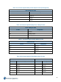
Table 1-8 32 Channel Hybrid 2U Rack Mount Alarm Pin Outs
Alarm In
Pin No.
Alarm Out
Assignment
Pin No.
Assignment
1
Input 1
1
Output 1
2
Input 2
2
Output 2
G
Ground
G
Ground
3
Input 3
3
Output 3
4
Input 4
4
Output 4
5
Input 5
5
Output 5
23
Alarm In
Pin No.
Alarm Out
Assignment
Pin No.
Assignment
G
Ground
G
Ground
6
Input 6
6
Output 6
7
Input 7
7
Output 7
8
Input 8
8
Output 8
G
Ground
G
Ground
9
Input 9
9
Output 9
10
Input 10
10
Output 10
11
Input 11
11
Output 11
G
Ground
G
Ground
12
Input 12
12
Output 12
13
Input 13
13
Output 13
14
Input 14
14
Output 14
G
Ground
15
Output 15
15
Input 15
16
Output 16
16
Input 16
N/A
N/A
17
Input 17
N/A
N/A
G
Ground
N/A
N/A
18
Input 18
N/A
N/A
Note:
Alarm Outputs are not supported.
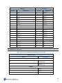
Table 1-9 32 Channel Hybrid 2U Rack Mount Audio Pin Outs
Audio Pin Outs
Pin No.
Assignment
Audio Out
S
Signal Out
(Not Supported)
G
Ground
(Not Supported)
Audio In
G
Ground
1
Input 1
2
Input 2
24
Audio Pin Outs
Pin No.
Assignment
3
Input 3
G
Ground
4
Input 4
5
Input 5
6
Input 6
G
Ground
7
Input 7
8
Input 8
9
Input 9
G
Ground
10
Input 10
11
Input 11
12
Input 12
G
Ground
13
Input 13
14
Input 14
15
Input 15
G
Ground
16
Input 16
Table 1-10 32 Channel Hybrid 2U Rack Mount Form C Relay Pin Outs
Form C Relay Pin Outs
Pin No.
Assignment
G
Ground
NO
Normally Open
C
Common
NC
Normally Closed
25
Table 1-11 32 Channel Hybrid 2U Rack Mount RS422 Pin Outs
RS422 Pin Outs
Pin No.
Assignment
RX +
Receive +
RX -
Receive -
TX -
Transmit -
TX +
Transmit +
Table 1-12 64 Channel Hybrid 3U Rack Mount Alarm Pin Outs
Alarms In
Pin No.
Alarms Out
Assignment
Pin No.
Assignment
1
Input 1
1
Output 1
2
Input 2
2
Output 2
G
Ground
G
Ground
3
Input 3
3
Output 3
4
Input 4
4
Output 4
5
Input 5
5
Output 5
G
Ground
G
Ground
6
Input 6
6
Output 6
7
Input 7
7
Output 7
8
Input 8
8
Output 8
G
Ground
G
Ground
9
Input 9
9
Output 9
10
Input 10
10
Output 10
11
Input 11
11
Output 11
G
Ground
G
Ground
12
Input 12
12
Output 12
13
Input 13
13
Output 13
14
Input 14
14
Output 14
G
Ground
15
Output 15
15
Input 15
16
Output 16
16
Input 16
17
Output 17
17
Input 17
18
Output 18
G
Ground
G
Ground
26
Alarms In
Pin No.
Alarms Out
Assignment
Pin No.
Assignment
18
Input 18
19
Output 19
19
Input 19
20
Output 20
20
Input 20
21
Output 21
G
Ground
G
Ground
21
Input 21
22
Output 22
22
Input 22
23
Output 23
23
Input 23
24
Output 24
G
Ground
G
Ground
24
Input 24
25
Output 25
25
Input 25
26
Output 26
26
Input 26
27
Output 27
G
Ground
G
Ground
27
Input 27
28
Output 28
28
Input 28
29
Output 29
29
Input 29
30
Output 30
G
Ground
31
Output 31
30
Input 30
32
Output 32
31
Input 31
N/A
N/A
32
Input 32
N/A
N/A
G
Ground
N/A
N/A
33
Input 33
N/A
N/A
34
Input 34
N/A
N/A
35
Input 35
N/A
N/A
G
Ground
N/A
N/A
36
Input 36
N/A
N/A
Note:
Alarm Outputs are not supported.
27
Table 1-13 64 Channel Hybrid 3U Rack Mount Audio Pin Outs
Audio Pin Outs
Pin No.
Assignment
Audio Out 1
S
Signal Out
(Not Supported)
G
Ground
(Not Supported)
Audio In
G
Ground
1
Input 1
2
Input 2
3
Input 3
G
Ground
4
Input 4
5
Input 5
6
Input 6
G
Ground
7
Input 7
8
Input 8
9
Input 9
G
Ground
10
Input 10
11
Input 11
12
Input 12
G
Ground
13
Input 13
14
Input 14
15
Input 15
G
Ground
16
Input 16
Alarm Out 2
S
Signal Out
(Not Supported)
G
Ground
(Not Supported)
28
Audio Pin Outs
Pin No.
Assignment
Audio In
G
Ground
17
Input 17
18
Input 18
19
Input 19
G
Ground
20
Input 20
21
Input 21
22
Input 22
G
Ground
23
Input 23
24
Input 24
25
Input 25
G
Ground
26
Input 26
27
Input 27
28
Input 28
G
Ground
29
Input 29
30
Input 30
31
Input 31
G
Ground
32
Input 32
Table 1-14 64 Channel Hybrid 3U Rack Mount Form C Relay Pin Outs
Form C Relay Pin Outs
Pin No.
Assignment
G
Ground
NO
Normally Open
C
Common
NC
Normally Closed
29
Table 1-15 64 Channel Hybrid 3U Rack Mount RS422 Pin Outs
RS422 Pin Outs
Pin No.
Assignment
RX +
Receive +
RX -
Receive -
TX -
Transmit -
TX +
Transmit +
Connecting the VideoEdge NVR to a Network
Connect the cable from the local area network to the Ethernet port. Use Category 5 twisted-pair Ethernet cable (CAT 5
TPE). For more information on configuration of network settings refer to Network Settings on page 225.
Rack Mounting the System
The VideoEdge Hybrid NVR rack-mounting chassis has pre-drilled holes to install the included rack slides. Mount the
unit by attaching rack slides to the chassis and using the included front mount rack holes.
Caution
You must mount the unit in a fully supported rack. Use rails rated for a minimum of 150 pounds that attach to both
sides of the unit and to the front and back of the rack. The rack must be equipped with EIA-310-D standard 19-inch
front and rear mounting flanges.
Safety for Rack Mountable Equipment
1
Elevated Operating Ambient - If installed in a closed or multi-unit rack assembly, the operating ambient temperature of the rack environment may be greater than room ambient. Therefore, consideration should be given
to installing the equipment in an environment compatible with the maximum ambient temperature (Tma) For
rack-mounted units is 35° C.
2
Reduced Air Flow - Installation of this equipment in a rack should be such that the amount of air flow required
for safe operation of the equipment is not compromised.
3
Mechanical Loading - Mounting of the equipment in the rack should be such that a hazardous condition is not
achieved due to uneven mechanical loading.
4
Circuit Overloading - Consideration should be given to the connection of the equipment to the supply circuit
and the effect that overloading of the circuits might have on overcurrent protection and supply wiring.
Appropriate consideration of equipment nameplate ratings should be used when addressing this concern.
5
Reliable Grounding - Reliable grounding of rack-mounted equipment should be maintained. Particular
attention should be given to supply connections other than direct connections to the branch circuit (e.g. use of
power strips).
30
Installation
Overview
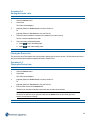
This section describes the initial setup of the VideoEdge Appliance.
VideoEdge Setup Wizard
Once the NVR has been installed you need to configure the NVR settings via the Setup Wizard. On completion your
NVR will be operational.This can be accessed using the VideoEdge Administrator icon on the NVR desktop or via a
remote client. On the first time accessing the NVR user interface after installation you will be automatically be directed
to the Setup Wizard.
Caution
The VideoEdge Administration icon has been added for convenience. 10.0 Firefox for SUSE Linux Enterprise SLE-11
is the supported browser for use with the NVR Administration Interface when accessing it locally on the NVR. When
accessing the NVR Administration Interface from a remote client PC, Internet Explorer Versions 9 & 10 or Firefox 10
are the supported browsers. Google Chrome and Safari are not supported.
Note:
If you exit the Setup Wizard prior to completing all the steps, the wizard will save your progress and automatically
return to the last page viewed of the Setup Wizard.
The wizard consists of the following menu items:
• Preparation
• System
• Network
• Devices
• System Security
• Finish
Procedure 1-2
Logging into the Wizard
Step
Action
1
Enter the Administrator Username.
2
Enter the Administrator Password.
- End -
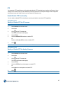
Preparation
This menu item describes the preparation stage of the Setup Wizard. The Welcome tab is displayed.
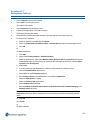
31
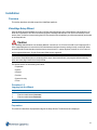
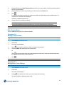
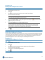
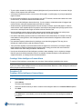
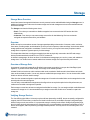
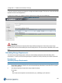
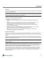
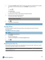
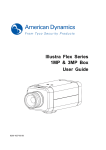
Welcome Tab
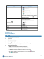
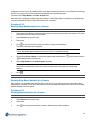
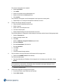
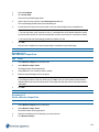
The Welcome tab is the first page of the Setup Wizard and allows you to select the language in which the
Administration Interface is displayed, to advance to the next page click Start.
Figure 1-12 Welcome Page
Procedure 1-3
Selecting the Language
Step
Action
1
Select the required language from the Choose Language dropdown.
2
Click Start and advance to the next page.
- End -
System
This System menu item displays the Support ID and allows system information to be edited.
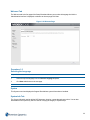
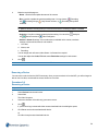
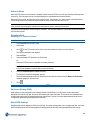
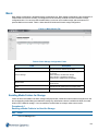
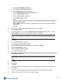
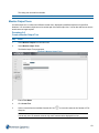
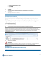
System Info Tab
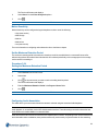
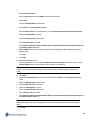
The System Info tab is used to edit the NVR hostname, location, current date and current time. You can also
download the NVR’s public key which is used for verifying the integrity of exported clips.
32
Caution
It is critical that you configure the correct Location and the Current Date/Time to ensure the VideoEdge Appliance is
fully operational on completion of the Setup Wizard and to ensure recorded media has the correct timestamp.
Figure 1-13 System Info Page
Procedure 1-4
System Info Settings
Step
Action
1
To edit the following fields:
• Hostname
• Location
• Current Date/Time
Select the current value. Edit the value as required.
2
Click Save.
3
Click Continue to advance to the next page.
- End -
Network
This section describes the network stage of the Setup Wizard and outline all LAN interface details.
33
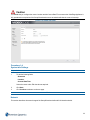
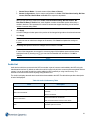
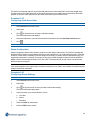
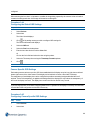
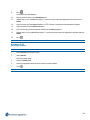
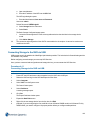
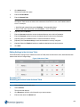
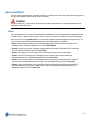
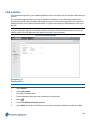
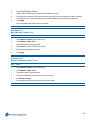
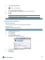
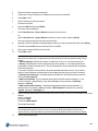
LAN Interface Tab
The LAN Interface tab is used to edit the LAN interface settings for each NIC including IP address allocation, LAN IP
address, subnet mask and IP broadcast.
The NVR can have multiple active NICs. This allows the use of dedicated camera networks.
Figure 1-14 LAN Interface Page
Procedure 1-5
LAN Interface Settings
Step
Action
1
To edit the LAN Interface settings, select Edit next to the NIC you want to modify. You can edit the following
fields:
• IP Address Allocation
Note:
To open the NVR Administration Interface the IP address of one of the NICs must be known, if all the
IP addresses are dynamic they will vary in value. It is recommended that a NIC is configured with a
static IP address and subnet mask for this reason.
• LAN IP Address
• Subnet Mask
• Default Gateway
Note:
The Subnet Mask is defined by three classes of IP Address A, B and C which will determine its
value. They are as follows:
34
1. Class A - First Octet Decimal Range 1-126, Subnet Mask Value 255.0.0.0
2. Class B - First Octet Decimal Range 128-191, Subnet Mask Value 255.255.0.0
3. Class C - First Octet Decimal Range 192-223, Subnet Mask Value 255.255.255.0
Class A addresses 127.0.0.0 to 127.255.255.255 cannot be used and are reserved for loopback and
diagnostic functions.
2
Edit the setting as required and click Save.
3
Click Continue to advance to the next page.
- End -
Devices
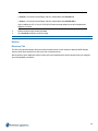
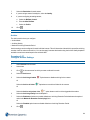
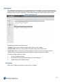
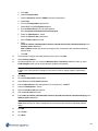
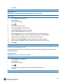
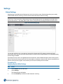
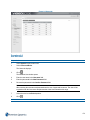
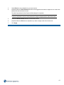
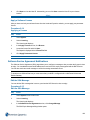
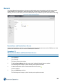
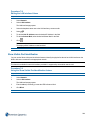
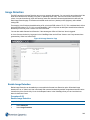
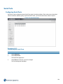
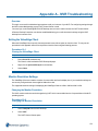
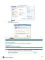
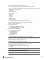
Discovery Tab
The Discovery tab automatically discovers all 'discoverable devices' on the network to add to the NVR. Multiple
devices can be discovered until you reach your limit of camera licenses.
Not all cameras can be added to the NVR in this way as some manufacturers require cameras to be pre-configured
prior to being added to a network.
35
Figure 1-15 Discovery Page
Procedure 1-6
Discovery Settings
Step
Action
The Discovery tab automatically displays all discovered devices.
Note:
If there are devices that you expected to be discovered, but are not displayed, you may need to add
these devices manually as some manufacturers do not have Discovery configured by default.
1
(Optional) Select the camera network NIC from the dropdown if you want to search for cameras on a particular NIC instead of across all NICs.
2
(Optional) Select the checkbox(es) of the device(s) you want to edit and click Change IP to edit the IP
address of a camera.
3
(Optional) Select the checkbox(es) of the device(s) you want to add to a Security Group and click Add
Security Group.
Refer to Security for further information.
4
Select the checkbox(es) for the device(s) you want to add to the NVR from the Discovered device list.
5
(Optional) De-select the Default Associations checkbox if video / audio association is not required.
6
Click Add.
The imported device(s) are displayed in the Video / Audio List tab
7
Click Continue to advance to the next page.
Note:
For further information on Camera and Device Discovery refer to Discovery for further information.
36
- End -
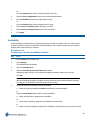
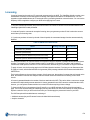
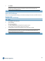
System Security
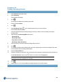
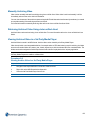
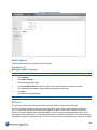
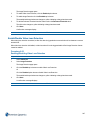
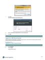
System Password Tab
The System Password tab allows you to change the root password for the NVR.
Caution
It is highly recommended for security reasons that you change the root password.
Note:
For security reasons, the System Password page must run under HTTPS.
Figure 1-16 System Password Tab (viewed in HTTP)
Procedure 1-7
Changing the System Password
Step
Action
1
Click Change to HTTPS.
A browser warning page displays to state there is a problem with the website's security certificate.
2
Select Continue to this website (not recommended).
Note:
Wording may differ between browsers.
The System Password page displays in HTTPS.
37
3
Enter the Current Password.
4
Enter the New Password.
5
Re-enter the New Password in the Confirm Password field.
Caution
It is extremely important that you remember this password. If necessary, you should write this password down and
store it securely.
6
Click
.
7
Click Continue to advance to the next page.
- End -
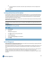
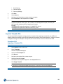
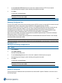
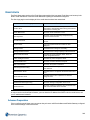
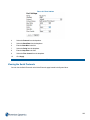
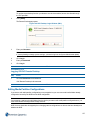
Finish
The Setup Wizard is now complete, you can use view video using the Select Video dropdown, launch the VideoEdge
Client or exit the wizard to the NVR Administration Interface.
38
Figure 1-17 Summary Page
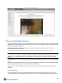
Setting up the VideoEdge Appliance
When the VideoEdge Appliance is setup default partitioning is configured including the required system partitions and
media partitions. If you add additional external storage to the NVR, you can configure the media partitions as required.
Refer to Storage for more information.
The NVR is supplied with its NIC eth0 enabled. It is set assigned a default static IP address of 10.10.10.10.
Remaining NICs will not be resolved.
The root SUSE account is assigned with the password nvr and is required to access the NVR's desktop.
Note:
In the interest of server security, the default root password should be changed at the earliest opportunity. Ensure you
make note of your chosen password as you will be unable to make administrative changes to the NVR's desktop
without it.
A VideoEdge account is created and assigned with the password VEclient and is required to access the VideoEdge
Client.
System settings including date and time must be configured during the Setup Wizard. You must also enable recording
on all analog channels with cameras connected during the Setup Wizard.
All other settings can be configured during the Setup Wizard or via the NVR Administration interface once set up is
complete.
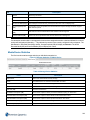
System Partitions
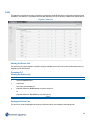
The tables outlined in this section describe the partitions set up by default on the NVR. There are several model
variations depending on the storage capacity supplied. For each NVR approximately 500GB of storage is required for
39
system partitions. The remaining storage available can be used for media storage and is configured as media
partitions.
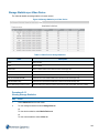
Models with 500GB capacity require additional external storage to be added and configured to record media. By default
no media storage partitions are configured on these devices.
Media partitions are configured to create one media partition for each hard drive, therefore utilizing all available storage
space.
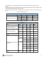
Table 1-16 System Partitions
System Partitions
All Models and All Model Types
Size
Type
FS Type
Mount Point
16 GB
Linux swap
Swap
swap
476 GB
Linux native
XFS
/var
8 GB
Linux native
Ext3
/
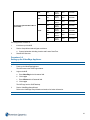
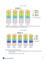
Table 1-17 Default Partitions
Partitions
Model
Media
Storage
Drive Size
Type
FS Type
Mount
Point
0TB
-
-
2TB
2TB
Linux
Native
XFS
/mediadb
0TB
-
Linux
Native
2TB
2TB
Linux
Native
XFS
/mediadb
18TB
13.6TB
Linux
Native
XFS
/mediadb
3TB
3TB
Linux
Native
XFS
/mediadb
3TB
Linux
Native
XFS
/mediadb
3TB
Linux
Native
XFS
/mediadb1
3TB
Linux
Native
XFS
/mediadb1
3TB
Linux
Native
XFS
/mediadb2
3TB
Linux
Native
XFS
/mediadb3
3TB
Linux
Native
XFS
/mediadb
13.6TB
Linux
Native
XFS
/mediadb
16 Channel Hybrid Desktop
32 Channel IP Only Desktop
32 Channel Hybrid 2U Rack Mount
(RAID)
6TB
32 Channel Hybrid 2U Rack Mount
(Non-RAID)
12TB
64 Channel Hybrid 3U Rack Mount
(RAID)
18TB
40
3TB
3TB
Linux
Native
XFS
/mediadb
3TB
Linux
Native
XFS
/mediadb
3TB
Linux
Native
XFS
/mediadb1
3TB
Linux
Native
XFS
/mediadb
3TB
Linux
Native
XFS
/mediadb1
3TB
Linux
Native
XFS
/mediadb2
3TB
Linux
Native
XFS
/mediadb3
6TB
64 Channel Hybrid 3U Rack Mount
(Non-RAID)
12TB
The setup process consists of:
1
Initial boot up of the NVR
2
Run the Setup Wizard and configure at minimum:
a
3
System Information including Location and Current Date/Time.
Restart NVR Services
Procedure 1-8
Setting up the VideoEdge Appliance
Step
Action
1
Power on the VideoEdge Appliance.
The NVR boots to the SUSE login window.
2
Login to the NVR.
a
Enter VideoEdge in the Username field.
b
Click LogIn.
c
Enter VEclient in the Password field.
d
Click Login.
The NVR logs into the SUSE desktop.
3
Run the VideoEdge Setup Wizard.
Refer to the VideoEdge Setup Wizard section above for further information.
- End -
41
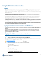
Using the NVR Administration Interface
Overview
The NVR Administration Interface allows users to interact with the NVR. This provides information about the server
and allows you to modify the server’s settings. The NVR interface is accessible via a web browser, through victor
unified client or locally on your hardware. All pages on the web client are static. You must refresh your browser to keep
all information current.
To access the NVR Administration Interface from a remote workstation, you must know its IP address and have a
User name and Password combination that is valid for the NVR.
A remote workstation logging into the NVR using the Administration Interface must have Java 6 or above installed. If
the workstation is connected to the Internet, but does not have Java installed, you must download Java from its
website http://www.java.com. You must also enable javascript on your browser.
To access the NVR through victor unified client, you must add the NVR Recorder to your recorders in the device list in
victor client. For information on how to add the NVR recorder to victor refer to Setting Up Recorder Devices in the
victor Configuration and User Guide.
This section explains how to log into the NVR Administration Web Interface, access the NVR Administration Interface
via victor unified client and provides an overview of the user interface.
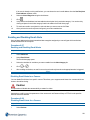
Logging into the NVR Administrator Interface via a Web Browser
To access the NVR Administrator Interface you must log in. There are two user accounts, System Administrator and
Operator.
If you log in using a System Administrator account you will have access to configure and edit all settings of the
NVR. If you log in using a Operator account, you do not have permissions to edit any of the settings, you can only
view the current settings and view live video.
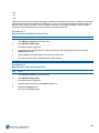
Procedure 1-9
Logging into the NVR Administrator Interface via a Web Browser
Step
Action
1
Launch your web browser and enter the NVR IP address into the URL field.
Enter https://NVR_Server_IP_Address, where NVR_Server_IP_Address is the IP address of the machine running
the NVR software, for example, http://192.187.100.21
2
The NVR login dialog box opens. Enter your User name and Password.
User name: admin
Default Password: VIDEO!edge23
Or
User name: operator
Default Password: VideoEdge
Note:
1. You are asked to login/authenticate when you:
42
- First log on to the NVR Administrator Interface.
- Are already logged on and your user access is changed.
2. If you have changed the account passwords, use these in place of the default password.
Figure 1-18 NVR Login Dialog
3
Click OK.
The Administration interface for the NVR opens.
- End -
victor NVR Administration Interface
To access the victor NVR Administration interface you must have the NVR added as a recorder in the device list on
your victor client. For information on how to add the NVR recorder to victor refer to the victor Configuration and User
Guide.
By configuring the NVR through victor you can configure your NVR in exactly the same way as via the web
Administration interface. However, when using victor you do not have the option to view live video. Instead use the
Surveillance pane in the victor client to view NVR cameras in live mode.
Procedure 1-10
Accessing the victor NVR Administration Interface
Step
Action
1
In the victor client, expand Recorders in the Device List.
2
Expand the VideoEdge folder.
3
Right-click on the NVR recorder you want to configure.
43
Figure 1-19 victor NVR Configure option
4
Select Configure.
The NVR Administration interface opens.
- End -
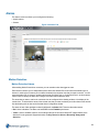
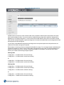
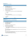
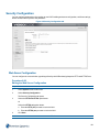
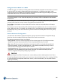
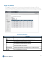
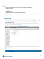
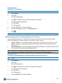
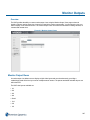
Navigating the NVR Interface
Figure 1-20 NVR Interface
To navigate the NVR Interface and access the required configuration settings, use the menu and sub menus down the
left of the page.
44
The menu is divided into several main areas:
• Live Video (web only)
• Devices
• Storage
• Archive
• System
• Network
• Advanced
• Monitor Outputs
• Logout (web only)
Each menu is further divided into sub menus for easy navigation to the required configuration settings.
Live Video Menu
The Live Video menu item is only available through the web NVR Administration interface. This section has sub
menus;
• 1 Camera View: Allows you to view and edit configuration for a single camera connected to the NVR.
• 2x2 Camera View: Allows you to view and edit configuration for up to 4 cameras simultaneously that are
connected to the NVR.
Devices Menu
The Devices menu has sub menu items;
• List - From here you can view a list of all devices connected to the NVR and view a summary of their
configuration status. You can add and remove devices or edit/batch edit cameras configuration settings.
• Alarms - You can create camera alarms, these may be for specific regions of a cameras view. You can also
select different types of alarm trigger, for example Motion Detection or Video Intelligence.
• Schedules - The scheduler allows you to specify the recording mode (including no recording) that is active at
scheduled times during the day.
• Security - The security page allows you to create and maintain camera password groups.
• Discovery - This section allows you to use auto-discovery to add cameras to the NVR.
Storage Menu
The Storage menu has sub menu items;
Basic: Use the Basic storage configuration option to assign devices available on the NVR as storage devices, edit
media folder settings of storage devices, and to allocate a vault media quota
Advanced: Use the Advanced configuration options to assign storage devices and cameras to Storage Sets.
Archive Menu
The Archive menu has sub menu items;
• Archives - Use to add/remove and configure Archive Destinations.
45
• Settings - Sub menu consists of two pages. Use the Global Settings page to configure Automatic
Archiving, Archive Culling, Retry Count and Retry Interval. Use the Availability page to configure time
periods when recorded video can be written to the archive.
• Archive Scheduler - Sub menu consists of three pages. Use Schedules page to enable the Archiving
Scheduler, create and edit Archiving Schedules.
• Device List - Use to edit the Archiving Mode, Quality and Maximum Archiving Retention Period.
• Jobs - Use to view or delete currently queued Archiving operations.
System Menu
The System menu has sub menu items; General, Users and Roles, Licensing, Templates, Backup/Restore and
Update Software, Serial Protocols and Security Configuration..
• General - Use to configure and edit general system information.
• Users and Roles - Use to edit role password settings.
• Licensing - Use to view your VideoEdge NVR license information, apply a license or upgrade your license.
• Templates - Sub menu consists of two pages. Use the Save Template page to create a custom template
based on the settings that are currently configured within the NVR, these include Camera Settings, Storage
Settings, User Information, Network Settings, Email Settings and Failover Settings. Use the Import
Template page to apply an existing template file to the NVR which will edit its settings accordingly.
• Backup/Restore - Sub menu consists of two pages. Use the Backup page to create a backup of the
Camera settings, System Settings, User information, DHCP Settings and NTP Settings. Use the Restore
page to upload a backup file to restore the NVR settings to the configuration of that Backup file.
• Update Software - Use to browse and upload a software upgrade package.
• Serial Protocols - Use to browse the Serial Protocols which are supported by the NVR.
• Security Configuration - Use to configure web server configuration, create self-signed certificates/create
certificate requests, enable/disable remote access and change the system password.
Network Menu
The Networks menu has menu items;
• General - Use to configure general network settings such as the Domain Name, Domain Name Servers,
Default Gateway, RTSP Port, NTP Status and NTP Servers.
• LAN Interface - Use to configure the available LAN interfaces. Each interface provides the option to
configure the IP Address allocation, LAN IP Address, Subnet Mask and IP Broadcast Address. If IP
Address allocation is set to either None or DHCP you will be unable to edit any of the entry fields. The menu
will also display the MAC Address of each Network Interface Controller (NIC) for information purposes.
• DHCP Server - Use the DHCP Server page to configure the DHCP Status for each NIC. The start and end
range of the IP Addresses to be included for each NIC during automatic searches for IP Devices can also be
configured. Use the DHCP Status page to view active devices which have been assigned an IP address by
the NVR when it is acting as a DHCP server.
• WAN Settings - Used to configure the NVR for operation on a Wide Area Network. In the WAN Settings you
can configure the WAN IP Address, HTTP Port, Secure HTTP Port and the Streaming Configured Port.
• Dynamic Bandwidth - Use to configure bandwidht throttling, when disabled there is no framedropping or
transcoding invoked. In the bandwidth throttling settings you can enable Transcode, select the number of
streams to be transcoded, up to four, select the Bandwidth Priority, Traffic smoothing, LAN and WAN bitrate
caps.
46
Advanced Menu
The Advanced Menu has sub menu items;
• Failover - Use the Failover page to configure the NVR to take over the camera and system settings of
another NVR on the network should it fail. Also use to view Failover events which have occurred using the
search tool in the Failover Events page.
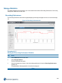
• Storage Statistics - Use the Rec Performance page to view a graph plotting the recording performance of
each storage set. Use the Disk Activity page to view a graph plotting the disk activity for a specific media
folder over a specific time period. Use the Storage Sets page to view storage statistics for each Storage
Set, use the Media Devices page to view storage statistics for each Device and use the Video page to view
storage statistics for each Camera.
• Stream Statistics - Use the Video Rec Statistics page to view a table of information relating to the
recording process of each camera added to the NVR. Use the Audio Rec Statistics page to view a table of
information relating to the recording process of each audio device added to the NVR. Use the Device
Streams page to view a summary of the configured stream settings for each device.
• Archive Statistics - Use to view graphs plotting the Total Throughput for all archives and Throughput per
archive.
• Logs - Use the Retrieve Logs page to customise the search criteria for retrieving log files, the criteria
includes date and time range searches, options to retrieve camera logs, recording pipeline descriptions,
camera firmware details and core files. The maximum size of the camera log file can be selected from a
predefined dropdown list. The FTP Log Management page provides the option to upload log files to an FTP
server. The Event Logs page is used primarily by American Dynamics technical support for troubleshooting.
It displays informational and error-related events that have occurred on the NVR system. The Connection
page displays the Camera Connection Errors that have occurred. The Camera Logs page provides
information on camera reboots, changed to camera recording status, and the use of Pan-Tilt-Zoom (PTZ) and
other controls. The Audit Trail page provides information on changes which have been made by a privileged
user including; system date/time, software upgrade, FTP log management, user login passwords and
network settings.
• Image Detection - Use to determine if a camera on the NVR is recording a very dark or potentially black
video. Once configured the test will run for each camera on the server once every minute.
• Email Alerts - Use the Email Alerts page to add email addresses to receive a number of predefined alerts.
The Alert Logs page displays a log of email alerts which have been transmitted from the NVR.
• Ping - Use to test communication between the NVR and other devices using a ping command.
• Serial Ports - Use to select the serial protocol to be used with each available port. You can also edit the
baud rate, data bits, parity, stop bits and flow control.
• Connected Clients - Use to display the IP Address of the device viewing the NVR via a client, for example,
victor unified client, VideoEdge Client or QuickTime. An entry for each camera being viewed from the NVR
is displayed with the corresponding IP Address, client type and streaming protocol.
• Reset to Factory Defaults - Use to reset the following of the NVR’s settings; Storage, Failover, User
Passwords and Alarm settings. Saved Media files (video/audio) can be erased, retained or retained and
re-indexed. Carrying out a Reset to Factory Defaults will have no affect on the NVR’s Linux based operating
system.
• Shutdown - Use to Restart NVR Services, Reboot the NVR and to Shutdown the NVR.
Monitor Output Menu
The Monitor Outputs page allows you to configure and send monitor layout presets to monitors attached to the
NVR.The Monitor Output Menu has sub menu items;
47
• Monitor Output Tours - Use to create Monitor Output Tours made up of different camera views.
• Monitor Output Presets - Use to create monitor outputs made up of camera inputs and tours.
Procedure 1-11
Navigating the NVR Interface
Step
Action
1
Select the required menu item from the main menu on the left-hand side of the page.
The selected menu item expands to display a sub menu list of items.
Note:
Live Video menu option is not available when browsing directly on VideoEdge NVR’s server browser
interface and is only available when connected from a remote system browser.
2
Select the required item from the sub menu list.
The relevant configuration settings are displayed in the main pane of the window.
3
(Optional) Select the tabs at the top of the main pane to navigate between pages.
- End -
48
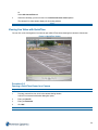
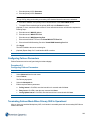
Live Video
Once the NVR system has been configured you can view live video streams. You can view live video using the Live
Video menu if you are remotely accessing the NVR Administration Interface.
If you access the NVR Administration Interface via victor client or locally from the NVR, the Live Video menu item is
not available. Use the Surveillance window in victor Client or the VideoEdge Client to view live video.
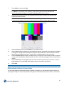
Live Video
The camera views on an NVR can display live video up to a maximum of 4 live video streams. A live audio stream is
not available on the NVR Administration interface. To listen to audio use victor unified client or VideoEdge Client.
Viewing Live Video on the NVR Web Interface uses Apple QuickTime, you must have a QuickTime player installed to
be able to view video. This allows you to view video within the web interface and as stand alone QuickTime windows.
You can download it from www.apple.com/quicktime. If you try to view Live Video and do not have QuickTime
installed you will be notified that a plugin is required. Selecting to Install the plugin will direct you to the Apple website.
You must have your storage and cameras configured before you can view live video.
Figure 2-1 Live Video View
Procedure 2-1
Viewing Live Video
Step
Action
1
Select Live Video from the main menu.
2
Select 1 Camera View tab
49
Or
Select 2x2 Camera View tab.
3
Select the camera(s) you want to view from the Select camera to view dropdown.
The camera’s live video stream displays in the viewing window.
- End -
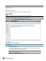
Viewing Live Video with QuickTime
You can click on the viewing area of a camera to open a QuickTime viewer showing that camera’s video stream.
Figure 2-2 QuickTime Viewer
Procedure 2-2
Opening a QuickTime Viewer for a Camera
Step
Action
1
From any camera live view, click in the camera viewing window.
A QuickTime Internet Authorization dialog box opens.
2
Enter your User ID.
3
Enter your Password.
4
Click OK.
- End -
50
Devices
Cameras, audio devices and text devices are added and configured using the Devices menu of the NVR
Administration Interface.
The Devices menu has the following menu items;
• List - From here you can view a list of all devices connected to the NVR and view a summary of their
configuration status. You can add and remove devices or edit/batch edit cameras configuration settings.
• Alarms - You can create camera alarms, these may be for specific regions of a cameras view. You can
also select different types of alarm trigger, for example Motion Detection or Video Intelligence.
• Scheduler - The scheduler allows you to specify the recording mode (including no recording) that is
active at scheduled times during the day.
• Security - The security page allows you to create and maintain camera password groups.
• Discovery - This section allows you to use auto-discovery to add cameras to the NVR.
51
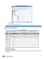
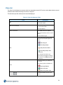
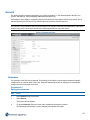
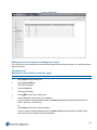
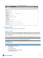
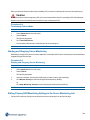
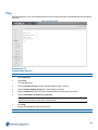
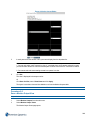
List
The List section provides a summary of all devices connected to the NVR and outlines configuration settings that are
available to view and edit. It is separated into three tabs displaying a list of all cameras, audio devices and text device.
Figure 3-1 Video List
Viewing the Device List
The device list provides a snapshot of the basic settings available on the NVR for all camera, audio and text devices
depending on the tab selected
Procedure 3-1
Viewing the Device List
Step
Action
1
Select the Devices menu.
2
Select List.
The Video List tab displayed.
3
(Optional) Select the Audio List tab to view the Audio List.
Or
(Optional) Select the Text List tab to view the Text List.
- End -
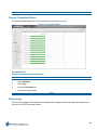
Sorting the Device List
The device list can be sorted alphanumerically by a selected column in ascending or descending order.
52
Procedure 3-2
Sorting the Device Lists
Step
Action
1
Select the Devices menu.
2
Select List.
The Video List tab displays.
3
(Optional) Select the Audio List tab to view the Audio List.
Or
(Optional) Select the Text List tab to view the Text List.
4
Select the column header from the device list table that you want to sort by.
The list is sorted in alphanumeric order.
5
Sort in ascending or descending order:
a
Select
to sort in ascending order.
b
Select
to sort in descending order.
- End -
Filtering the Device List
The device list has a Filter feature which can be used to display specific device records. The filter feature will look at
the criteria entered and compare this against all fields in the device list.
Procedure 3-3
Filtering the Device Lists
Step
Action
1
Select the Devices menu.
2
Select List.
The Video List tab displays.
3
(Optional) Select the Audio List tab to view the Audio List.
Or
(Optional) Select the Text List tab to view the Text List.
4
Enter the filter criteria into the Search field.
The device list is filtered to display only devices that meet the criteria entered.
Note:
The device list will filter as you type the criteria into the Search field. As the criteria gets more
specific the list filters accordingly.
- End -
53
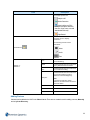
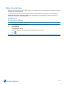
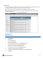
Video List
The Video List tab displays the cameras which have been added to the NVR. Devices can be added, edited, removed
and batch edited. Advanced settings can also be configured.
The table below provides a description of each field displayed.
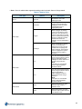
Table 3-1 Video List Summary Table
Field
No
Name and IP Address
Description
Device slot number.
Device name as given when adding
the device to the NVR.
Device IP address.
Device Information
Device Manufacturer and Model
FW: Current Firmware version on the
device
Communications Type.
Displays the device recording state.
There are four available options to
select:
Rec
•
Recording Off
•
Recording Always
•
Only Record on Alarm
•
Recording Always With
Alarm On
If the scheduler is enabled, you
cannot change the device recording
state and the icon,
in the field.2
is displayed
Indicates if archiving is enabled for
the device.
The archiving options available are:
Arch
Analytics
•
Archiving Disabled
•
Archive all video
•
Archive only alarm video
Indicates if analytics are set on the
device.
54
Field
Description
The analytic options are:
•
Analytics Off
•
Motion Detection
•
•
Video Intelligence (This
ecompasses object detection,
direction, linger, enter, exit and
abandoned/removed).
Edge Based.
Indicates the device's associations,
hover the cursor to display
information.
The following devices can be
associated:
Associations
Stream 1 /
Stream 2
•
Video
•
Audio
•
Text
Live
Indicates that this stream will be used
for live streaming.
Alarm
Indicates that this stream will be used
for any alarms that are recorded.
Rec
Indicates that this stream will be used
for non-alarm recording.
Indicates that this stream will be used
for executing analytics (motion
detection or video intelligence).
Analytics
Note
If an alarm is raised for motion
detection, the alarm stream is used to
record the alarm.
Codec
The camera codec.
FPS
The camera FPS.
Resolution
The camera resolution.
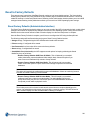
Adding Devices
Cameras can be added to the NVR in the Video List tab. There are two methods used for adding cameras; Manually
and using Auto Discovery.
55
Manually Adding Analog Devices
To add an analog device to the NVR you must connect the device directly to a port on the NVR unit.
The analog device ports must be opened on the NVR by adding an device on the Device List page using the IP
address, 127.0.0.1. Once a device with this IP address is added to the NVR, all analog ports are opened and all
devices are displayed in the Device List.
When the connection has been established between the NVR and the analog ports on the unit, all devices will always
display on the Device List even if a device is physically disconnected from the NVR unit.
You can ensure all cameras are connected by viewing the camera’s live video in the Live Video window. If no picture is
displayed for an analog camera, the camera needs to be connected to a port on the NVR.
The default recording mode for analog cameras when connected to the NVR is Recording Off.
Note:
If you remove an analog device from the NVR you can re-add it manually using the IP address 127.0.0.1, this will add
all inputs which are not currently in the Device List. Alternatively if you un-check the Add All Inputs on Device
checkbox you can select the inputs you want to add. This behavior is the same for all multichannel devices.
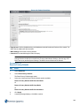
Procedure 3-4
Manually Adding Analog Devices
Step
Action
1
Select Devices from the main menu.
2
Select List.
The Video List tab displays.
3
Click
4
Enter a Device Name.
Note:
1. All devices added as part of a multichannel encoder are named using the following conventions;
- Video inputs are given a “_n” suffix, for example Analog_1 and so on.
- Audio inputs are given a “_n_audio” suffix for example Analog_2_audio.
2. In these examples, Analog is the user defined device name. Each device can be renamed once
they have been added to the NVR.
5
Enter 127.0.0.1 into the Device IP Address field.
6
Select the required Security Group from the Security Group dropdown.
7
(Optional) De-select the Add All Inputs on Device checkbox if you do not want to add all inputs on a
device.
8
(Optional) De-select the Default Associations checkbox if you want to define custom associations after the
devices have been added.
9
(Optional) Rename the analog devices by entering a new device name in the Name field.
10
Click
.
If the Default Associations checkbox is unselected a window will open displaying the available inputs. For
video devices a snapshot can be displayed.
56
All analog ports available on the NVR are opened and all devices that are connected to the NVR are displayed
in the Device List.
- End -
Manually Adding an IP Device
When a device is manually added to the NVR the default recording mode is set to "Recording Always". When adding a
camera were the configuration does not support Motion Detection (using either a primary or secondary stream) then
the default recording mode will be "Record Always".
Note:
The NVR is by default configured to attempt communicating with the camera using the cameras own native
commands. Using native camera handlers provides the maximum number of camera features available. If the NVR
does not support your camera brand, it will then attempt to use the general ONVIF communications protocol to
communicate with the camera. If the camera supports ONVIF you will be able to access one or more of the camera
features (for example; video, audio, PTZ, dry contact events). You can determine which communication method has
been employed by the NVR from the device list.
When you add an encoder to the NVR, all cameras associated with this encoder will have the same IP address. As a
result, these cameras must be assigned to the same password group and have the same dry contact settings. If you
edit either the password group or the dry contact settings for one camera associated with the encoder, these settings
will be updated for all cameras.
Procedure 3-5
Manually Adding an IP Device
Step
Action
1
Select the Devices menu.
2
Select List.
The Video List tab displays.
3
Click
4
Enter the Device Name.
5
Enter the Device IP Address of the device.
6
Select the Security Group from the Security Group dropdown.
Note:
The Security Group will usually be set by default. The NVR will use the manufacturer’s default
password to connect to the camera. However, if you have changed the password for this camera,
you need to assign the camera to the appropriate password group, or create a new password group.
7
Click Apply.
8
(Optional) De-select the Add All Inputs on Device checkbox if you do not want to add all inputs on a
device.
57
9
(Optional) De-select the Default Associations checkbox if you want to define custom associations after the
devices have been added.
10
(Optional) Rename the devices by entering a new device name in the Name field.
11
Click
.
If the Default Associations checkbox is unselected a window will open displaying the available inputs. For
video devices a snapshot can be displayed.
The device is added to the device list.
12
Configure the device settings as required.
Note:
Devices can be added to the NVR using Discovery. For further information refer to Discovery.
- End -
Edit a Camera Name
You can update the name given to a camera as required.
Procedure 3-6
Editing a Camera Name
Step
Action
1
Select Device from the main menu.
2
Select List.
3
The Video List tab displays.
4
Click
5
Select the Name field and enter the new camera name.
in the camera row where you want to change the camera name.
Or
Click
in the camera row where you want to change the camera name, select the General tab and enter
the new camera name into the Video Name field.
6
Click
- End -
Procedure 3-7
Editing Basic Video Settings
Step
Action
1
Select Devices from the main menu.
2
Select List.
The Video List tab displays.
3
Select
in the camera row for which you want to edit a video list setting.
The fields available to update are ready to edit.
58
4
Make the required changes to:
• Name - Use this field to update the name of the camera.
• Rec - Use this to update the camera recording state. You can choose,
Off,
Recording Always,
Alarm On.
Only Record on Alarm, or
Recording
Recording Always With
Note:
To update a camera’s recording state you must ensure the device recording scheduler is disabled.
• Analytics - Use this to change the analytic alarm setting. You can select,
Off,
Motion Detection or
Analytics
Video Intelligence.
• Stream1 / Stream 2 settings. If a second stream is available on the camera, use these
settings to select which stream is to be used for:
c
Live video,
d
Alarms, and
e
Recording.
You can assign each of these to either Stream 1 or Stream 2 as required.
You can also adjust the Codec, FPS and stream Resolution settings for each stream.
5
Click
- End -
Removing a Device
You can remove a device from the NVR if necessary. Once you remove a device from the NVR, you will no longer be
able to view live video, record media or access the device via a client.
Procedure 3-8
Removing a Device
Step
Action
1
Select Devices from the main menu.
2
Select List.
The Video List opens.
3
Select the checkbox of the device(s) you want to remove.
4
Click
If you are removing a camera which has an associated audio device a dialog box opens.
5
Click Yes to remove the associated audio device.
Or
Click No to keep the associated audio device.
59
A dialog box opens for confirmation that you want to remove the device(s).
6
Click Yes to remove the device(s).
The device(s) are removed from the NVR.
- End -
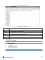
Batch Camera Configuration
Some camera settings can be batch edited. The Batch Edit tab lists the cameras currently being edited in the left
pane, and the setting adjustments are made in the right pane. When a change is made to a setting, the checkbox next
to the setting is checked. If you deselect the checkbox, the adjustment will not be applied.When you click apply, the
changes being made are previewed, with the new settings highlighted in yellow.
Procedure 3-9
Batch Editing Camera Settings
Step
Action
1
Select Devices from the main menu.
2
Select List.
3
Select the checkbox for each camera you want to batch edit.
4
Click
The Batch Edit tab displays.
5
Adjust the device settings:
a
Name - Use this field to update the name of the cameras.
Note:
When you update the name of devices using batch edit, each device will have a number appended to
its name. For example, CameraName_1, CameraName_2, etc.
b
Maximum Storage Per Device - Select from the dropdown to set the maximum duration over which
media recorded for these devices will be saved without being deleted.
c
Storage Set - Select from the dropdown which storage set the batch of devices will record to.
d
Recording Mode - Use this to set the recording mode for these cameras. You can choose,
ing Off,
e
Recording Always,
Only Record on Alarm, or
Recording Always With Alarm On.
Archiving Mode - Use to set the archiving mode for these cameras. You can choose,
abled,
Archive all videos or
Record-
Archiving dis-
Archive only alarm video.
f
Archiving Quality - Archiving Quality is defined as a percentage of applied framerate decimation. Archiving quality is applied in 10% intervals where 10% provides the lowest quality video and 100% provides
the highest quality video for archiving.
g
Maximum Archiving Retention Period - Select from the dropdown if an archiving retention period is
Enabled or Disabled.
h
Video Analysis - Select from the dropdown which type of analytics to apply to this batch of cameras.
i
Associate Audio - Use to associate an audio device with the selected cameras.
60
j
Stream Record Modes - Set each stream to Live, Alarm or Record.
k
Stream Configurations - Set the stream configurations for Codec, FPS, Resolution Quality, Bit Rate
Control, Bit Rate, Max Bit Rate and Profile in the respective dropdowns.
Note:
When you are selecting a value for the Codec, FPS, Resolution Quality, Bit Rate Control, Bit
Rate, Max Bit Rate and Profile fields, each dropdown contains the available options followed by a
number in brackets. This represents the number of cameras that support the setting over of the total
number of cameras being edited.
6
Click Apply.
A Confirm Changes window opens with a preview of the changes being made to the selected cameras.
7
Click Apply.
Note:
If you do not want to make these changes to all cameras, click Cancel and update the settings as
required.
8
A message box opens to confirm the changes were successful. Click OK.
Note:
If some of the changes are not successful, a summary page of failed updates opens with the failures
highlighted in red. By hovering over
continue.
you can view more detailed error information. Click OK to
- End -
Audio List
Audio devices which are connected to the NVR, an encoder or part of a camera can be added to the NVR using the
Administration Interface. By default an audio source which is physically built into a camera will be associated with that
camera. You can de-couple the audio input when adding the device manually or using Auto Discovery. The
association can also be removed at any stage using the device list.
The Audio List displays the audio devices which have been added to the NVR.The table below provides a description
of each field displayed.
Table 3-2 Audio List Summary Table
Field
No
Name and IP Address
Description
Device slot number.
Device name as given when adding the device to
the NVR.
Device IP address.
Device Manufacturer and Model.
Device Information
FW: Current Firmware version on the device.
Rec
Displays the device recording state. There are four
available options to select:
61
Field
Description
•
Recording Off
•
Recording Always
•
Only Record on Alarm
•
Recording Always With Alarm On
If the scheduler is enabled, you cannot change the
device recording state and the icon,
displayed in the field.2
is
Indicates the device's associations, hover the
cursor to display information.
The following devices can be associated:
Associations
•
Video
•
Text
Codec
The audio codec.
Volume
The current volume.
Bitrate
The current bitrate.
Procedure 3-10
Editing Audio Settings
Step
Action
1
Select Devices from the main menu.
2
Select List.
The Video List tab displays.
3
Select the Audio List tab.
4
Select
in the audio record for which you want to edit a audio list setting.
The fields that you can update are ready to edit.
5
Make the required changes to:
• Name - Use this field to update the name of the audio device.
• Enabled - Use the Enabled dropdown to enable or disable audio.
• IP Address - Use this field to update the IP address of the audio device.
• Rec - Use this to update the camera recording state. You can choose,
Off or
Recording
Recording Always.
62
Note:
To update a audio device’s recording state you must ensure the device recording scheduler is
disabled.
• Codec - Use the dropdown to select the codec when available.
Note:
The supported codec for analog channels is G711mulaw.
• Volume
• Bitrate - Use the dropdown to select the bitrate when available.
Note:
The supported audio bit rate for analog channels is 8000.
6
Click
- End -
Text List
Text devices can be added to the NVR either via serial or IP connections. Text devices provide a text based search
ability when associated with camera and audio devices; for example a compatible cash register can be added to the
NVR which will record the text data received from the register. Cameras and audio devices in the vicinity of the cash
register can then be associated with it, when you perform a text based search using the VideoEdge Client, associated
video and audio will be returned which was recorded at the time the text data was received.
The Text List displays the serial and IP text devices which have been added to the NVR.The table below provides a
description of each field displayed.
Table 3-3 Text List Summary Table
Field
Description
No
Device slot number.
Stream Name
Device name as given when adding the device to
the NVR.
Comms Type
Indicates Communication type in use.
Indicates the devices associations, hover the cursor
to display information.
The following devices can be associated:
Associations
Description
•
Video
•
Audio
Indicates configured settings.
Configuring Port Settings Prior to Adding a Serial Text Stream Device
Prior to adding a Serial Text Stream device you should ensure it is connected to one of the NVR’s USB ports or its
RS232 Serial port. Once connected you are required to configure that Serial Port’s communication protocol for Text
63
Stream use.
Procedure 3-11
Configuring Serial Port Settings for a Serial Text Stream Device
Step
Action
1
Select the Advanced menu.
2
Select Serial Ports.
The Serial Ports tab displays
3
Select Edit next to the Serial Port you want to edit.
The Port Settings dialog box opens.
4
Select Text Stream from the Protocol dropdown.
The following default settings are applied:
• Baud Rate - 4800
• Data Bits - 8
• Parity - None
• Stop Bits - 1
• Flow Control - None
5
Click Apply.
- End -
Manually Adding a Text Stream Device
Text Stream devices can be connected via serial or IP communications, using the Text list tab.
Procedure 3-12
Manually Adding Text Stream Devices
Step
Action
1
Select the Devices menu.
2
Select List.
The Video List tab displays.
3
Select the Text List tab.
4
Click
5
Enter a Text Stream Name.
6
Select the Connection Type from the dropdown.
7
Enter the Line Delimiter or click Default to use the default value.
64
Note:
If the Line Delimiter does not properly match what is used in the Text Stream then text may be lost or
improperly stored in the media database.
8
(IP Only) Enter the Port. Continue to step 11.
Note:
The port number must match the port number assigned on the Text Stream device.
9
(Serial Only) Select the option button of the Serial Device you want to use. Continue to step 10.
10
(Optional) Select
11
to edit the serial device settings:
a
Enter the Com Port.
b
Enter the Protocol.
c
Select the Baud Rate from the dropdown.
d
Select the Data Bits from the dropdown.
e
Select the Parity from the dropdown.
f
Select the Stop Bits from the dropdown.
g
Select the Flow Control from the dropdown.
h
Click Apply.
Click Apply.
- End -
Procedure 3-13
Editing Text Settings
Step
Action
1
Select Devices from the main menu.
2
Select List.
The Video List tab displays.
3
Select the Text List tab.
4
Select
in the text record for which you want to edit a text list setting.
The fields that you can update are ready to edit.
5
Make the required changes to:
• Text Stream Name - Use this field to update the name of the Text device.
• Connection Type - For information only when device is added.
• Line Delimiter - Use this field to update the Line Delimiter value.
• Port - For information only when device is added.
6
Click Apply.
- End -
65
Adding Rules and Markers
Rules are text matching instructions that can be used to define real-time Text Stream alarms using the NVR
Administration Interface, or to search recorded Text Streams after-the-fact using VideoEdge Client. For example, you
can use a Rule to trigger an alarm whenever the string “VOID” is detected in the stream, or you can use a Rule to
search for any time a particular field is greater than $20.00.
Markers are strings that identify the beginning of a new message in the Text Stream. For example, if your Text Stream
contains a stream of receipts from a POS system, you can use a Marker to identify each new receipt that comes in the
stream. If your receipts always have “Store 15” printed at the top, then use this as a Marker in the stream. When “Store
15” appears in the Text Stream, all the subsequent text until the next “Store 15” is seen will be stored and displayed
together as a single message.
Procedure 3-14
Adding a Rule to a Text Device
Step
Action
1
Select Devices from the main menu.
2
Select List.
The Video List tab displays.
3
Select the Text List tab.
4
Select the checkbox of the Text device you want to create a rule for.
5
Click
The Rules/Markers tab displays.
6
Click
The Rule Definition Window opens.
7
Enter the Name.
8
Enter a match in the Match with field.
9
Select the Search Direction from the dropdown. Forward by default.
10
Select the number of words from the Jump N Results dropdown, to skip after a match is found, to find the
associated value. Default = 0.
11
Select one of the following Criteria from the dropdown:
• found - Any results found.
• string - A series of characters in Value 1 field.
• less than - Less than Value 1.
• greater than - Greater than Value 1.
• equal to - Equal to Value 1
• range - Values between Value 1 and 2.
12
Enter a value in the Value1 field. This is required when using string, less than, greater than, equal to and
range Criteria.
13
Enter a value in the Value2 field. This is required when using range criteria.
14
Click Apply.
66
- End -
Procedure 3-15
Editing a Rule
Step
Action
1
Select Devices from the main menu.
2
Select List.
The Video List tab displays.
3
Select the Text List tab.
4
Select the checkbox of the Text device you want to edit a rule for.
5
Click
The Rules/Markers tab displays.
6
Select the checkbox of the Rule you want to edit.
7
Select
.
The Rule Definition Window opens.
8
Edit the Name.
9
Edit the match in the Match with field.
10
Select the Search Direction from the dropdown.
11
Select the number of words from the Jump N Results dropdown.
Or
From the Jump N Results dropdown, select To last entry of line to skip a variable number of entries between
the last match and the text value in a receipt.
12
Select the Criteria from the dropdown:
13
Edit the value in the Value1 field. This is required when using string, less than, greater than, equal to and
range criteria.
14
Edit the value in the Value2 field. This is required when using range criteria.
15
Click Apply.
- End -
Procedure 3-16
Add a Marker to a Text Device
Step
Action
1
Select Devices from the main menu.
2
Select List.
The Video List opens.
3
Select the Text List tab.
4
Select the checkbox of the Text device you want to create a marker for.
67
5
Click
The Rules/Markers page opens.
6
Click
The Marker Definitions Window opens.
7
Enter the marker Name.
8
Enter the Beginning Marker.
9
Click Apply.
- End -
Procedure 3-17
Edit a Marker
Step
Action
1
Select Devices from the main menu.
2
Select List.
The Video List opens.
3
Select the Text List tab.
4
Select the checkbox of the Text device you want to edit a marker for.
5
Click
The Rules/Markers page opens.
6
Select the checkbox of the Marker you want to edit.
7
Select
The Marker Definitions Window Opens.
8
Edit the marker Name.
9
Edit the Beginning Marker.
10
Click Apply.
- End -
Procedure 3-18
Removing a Rule or Marker from a Text Device
Step
Action
1
Select Devices from the main menu.
2
Select List.
The Video List opens.
3
Select the Text List tab.
4
Select the checkbox of the Text device you want to remove a rule/marker from.
68
5
Click
The Rules/Markers page opens.
6
Select the checkbox of the rule/marker you want to remove.
7
Click
- End -
Grouping Rules
Rules can be grouped together using the Group Rules checkbox, for both Text Stream alarms and searches. Grouping
rules creates an ‘AND’ logic so that all the grouped rules must be satisfied. When the Group Rules checkbox is
selected, it applies to all rules that have been added to the alarm or search definition. Rules that have been disabled
will not need to be satisfied..
Note:
When the Group Rules checkbox is applied the individual rules will not display in the Alarm Rule dropdown of an
events form in the VideoEdge Client. The only selectable option available will be ‘All’.
Procedure 3-19
Grouping Rules
Step
Action
1
Select Devices from the main menu.
2
Select List.
The Video List opens.
3
Select the Text List tab.
4
Select the checkbox of the Text device for which you want to group rules.
5
Click
The Rules/Markers page opens.
6
Select the Group Rules checkbox.
- End -
Advanced Text Device Configuration
Advanced Text Device Configuration includes creating video and audio associations with text stream devices and
creating of Rules and Markers.
Creating Associations for Text Devices
Text devices can be associated with multiple cameras and audio devices.
69
Procedure 3-20
Associating Cameras and Audio Devices with Text Devices
Step
Action
1
Select Devices from the main menu.
2
Select List.
The Video List opens.
3
Select the Text List tab.
4
Click
in the text record for which you want to edit a text list setting.
The Text Edit tab displays.
5
Select the checkbox(es) for the video and audio device(s) you want to associate with the text device.
6
Use the arrow right button
7
Click Apply.
to move the selected devices to the Association list(s).
- End -
Procedure 3-21
Removing Associations from Text Devices
Step
Action
1
Select Devices from the main menu.
2
Select List.
The Video List opens.
3
Select the Text List tab.
4
Click
in the text record for which you want to edit a text list setting.
The Text Edit tab opens.
5
Select the checkbox(es) for the video and audio device(s) you no longer want to be associated with the text
device.
6
Use the arrow left button
7
Click
to remove the selected devices from the Association list(s).
- End -
Advanced Camera Configuration
There are several advanced camera configuration tabs which are accessed by clicking the Setup icon in the Video List
tab;
• General
• Image Settings
• Function & Streams
70
• Archive
• Alerts
• PTZ
• OSD
General
General camera settings that can be easily updated from the General tab which can be accessed by clicking the Setup
icon for the required device on the Video List tab.
Note:
The MAC Address, ID Channel and Device Type fields are for information only and are not configurable.
Change the Security Group Assigned to an IP Camera
If an IP camera is assigned to a security group and you have changed the password for this camera, you will need to
select the new security group the camera belongs to.
Procedure 3-22
Changing the Security Group Assigned to an IP Camera
Step
Action
1
Select Devices from the main menu.
2
Select List.
3
Click
in the camera row that you want to assign to a new password group.
The Function & Streams tab displays.
4
Select the General tab.
5
Select the new password group from the Security Group dropdown.
6
Click
Note:
If you are editing the security group for a camera, forming part of an encoder device, all cameras
related to this device will be updated with the new security group. In this instance, a warning
message opens informing you that multiple cameras will be updated.
- End -
Change a Camera’s Storage Set
Changing the storage set a camera is assigned to is only applicable if you have configured the NVR for advanced
storage. When you change the storage set, media from the camera will now be stored on media folders in the new
storage set. You can also edit the storage set a camera is assigned to by editing the advanced storage settings, refer
to Advanced Camera Configuration on page 142.
71
Procedure 3-23
Changing a Camera’s Storage Set
Step
Action
1
Select Devices from the main menu.
2
Select List.
3
Click
in the camera row that you want to assign to a new storage set.
The Function & Streams page opens.
4
Select the General tab.
5
Select the new storage set from the Storage Set dropdown.
6
Click
- End -
Look-Down
Look-down should be enabled if a camera has been mounted on the ceiling pointing directs down to the floor. This is to
facilitate POS analytics. Refer to the victor unified user guide for more information.
Procedure 3-24
Enable/Disable Camera Look-down
Step
Action
1
Select Devices from the main menu.
2
Select List.
3
Click
4
Select the General tab.
5
Select the Look-down checkbox to enable look-down.
in the camera row that you want to enable/disable look-down for.
Or
Deselect the Look-down checkbox to disable look-down
6
Click
- End -
Video Streaming
You can enable or disable streaming on a camera as required.
Procedure 3-25
Enable/Disable Video Streaming
Step
Action
1
Select Devices from the main menu.
2
Select List.
72
3
Click
in the camera row that you want to assign to a new storage set.
The Function & Streams page opens.
4
Select the General tab.
5
In the Camera Streaming field select Enable to enable camera streaming,
Or
Select Disable to disable camera streaming.
6
Click
- End -
Image Settings
Camera image settings can be configured in the Image Setting tab which can be accessed by clicking the Setup icon
for the required device on the Video List tab.. The settings available are dependent on the camera make/model. When
the changed settings are applied, the viewer window updates to reflect the changes made.
Procedure 3-26
Configuring Camera Image Settings
Step
Action
1
Select Devices from the main menu.
2
Select List.
3
Click
in the camera row you want to configure camera settings.
The Function & Streams tab displays.
4
Select the Image Settings tab.
5
Adjust the Video Properties as required. The available settings and value ranges are dependent on the
camera make/model and include:
6
a
Video Standard - Select the required video processing standard from the dropdown.
b
Rotate Image - Select the angle you want to rotate the image from the dropdown.
c
Brightness - Select the brightness value from the dropdown.
d
Contrast - Select the contrast value from the dropdown.
e
Hue - Select the hue value from the dropdown.
f
Sharpness - Select the sharpness value from the dropdown.
g
White Balance - Select the white balance control value from the dropdown.
h
Back Light Compensation - Select the back light compensation value from the dropdown.
i
Image Interlaced - Select the image interlacing setting from the dropdown.
Adjust the Lens/Sensor settings. The types of settings and value ranges available are camera make/model
dependent and include:
a
LensFocus - Select a focus for the camera from the dropdown.
b
Lens Auto Focus - Select the checkbox to enable automatic camera focus.
c
Lens Iris - Select the iris value for the camera from the dropdown.
73
d
Lens Auto Iris - Select the checkbox to enable automatic iris control.
e
Lens Day Night Mode - Select the required mode from the dropdown.
f
Lens WDR (Wide Dynamic Range) - Select the checkbox to enable WDR.
g
Mount Type (Vivotech Fish-eye camera only) - Select the Mount type from the dropdown.
Note:
The mount point configured on the NVR must match the location of the Vivotech Fish-eye camera
when it is installed as this will dictate the algorithm used by victor unified client for de-warping.
7
Click
The viewer window updates to reflect the changes made to the image settings.
- End -
Function and Streams
The Function and Streams tab is where you configure:
• Recording Mode
• Video Analysis
• Motion Sensitivity (Motion Detection only)
• Maximum Retention Period
• Associate Audio
• Stream Configuration
Recording Mode
The recording mode setting on the camera determines when the camera records. .
Table 3-4 Recording Statuses
Mode
Icon
Description
Recording Off
Camera is not recording. Live
video can still be viewed.
Recording Always
The camera will record
continuously. In this mode you
will not receive alert notifications
from the NVR.
Only Record on Alarm
Camera is not recording an
alarm is detected recording
commences. Using this mode
you will receive alert notifications
from the NVR.
Recording Always with Alarm
On
Camera is recording
continuously with alarm
detection (bump-on-alarm).
Using this mode you will receive
alert notifications from the NVR.
74
Procedure 3-27
Setting the Camera Recording Mode
Step
Action
1
Select Devices from the main menu.
2
Select List.
3
Click
in the camera row you want to configure camera settings.
The Function & Streams tab displays.
4
Select the required Record Mode option button:
• Recording Off
• Recording Always
• Recording Normal Off, Alarms On
• Recording Always with Alarm On
5
Click
Note:
You can check the recording mode of any camera in the Live Video windows. The recording mode is
displayed beside the camera name.
- End -
Video Analysis
Video Analysis can be enabled using the dropdown to select one of the following:
• Motion Detection
• Video Intelligence
• Edge Analytics
Motion Detection
The NVR provides server-based motion detection for all cameras. Hardware-based (camera-based) Motion Detection
is not supported by the NVR. The NVR supports two motion detection features:
• Motion Search - a VideoEdge Client or victor Client can search recorded video for motion.
• Motion Alerts - you can define Motion detection settings that can be used to set up motion detection rules.
When a new camera is added to the NVR, a motion detection alert is automatically created with a full-view
region. The name of this alert will be called “Full View”.
The Motion Detection settings allow you to define the parameters which will initiate an alarm. This will reduce the
number of unwanted alarm events and is achieved using the following tools:
• Duration settings allowing you to define the time period of activity in the region of interest to activate an
alarm.
• Direction settings allowing you to define the direction of motion required to activate an alarm.
75
• Size expressed as the minimum percentage of the region of interest with activity required before activating
an alarm.
Motion Detection events will create entries in the victor site manager database. If required you can use the Reports
feature in victor unified client to retrieve event information.
Enabling Motion Detection
A Stream Configuration is required that allows the NVR to generate meta-data for motion detection. You also need to
select Motion Detection from the Video Analysis dropdown. The NVR will automatically determine the required
stream settings (Table 10-1). If only one stream is configured and it does not satisfy the requirements for Motion
Detection, the NVR will attempt to automatically open the second stream with settings best suited for Motion
Detection. If the camera does not support dual streaming you will manually need to adjust the configuration of the
configured stream.
Motion Detection may not be available on a camera if it’s minimum video resolution setting is higher than the
maximum acceptable resolution for Motion Detection. The NVR will not allow you to configure a camera for Motion
Detection if the resolution setting of the camera is higher than the settings in the table below.
Table 3-5 Camera Resolutions for Motion Detection
Camera Type
Minimum Resolution
Maximum Resolution
MJPEG
QCIF
1280 x 960
MPEG-4
QCIF
CIF
The optimal stream to perform Motion Detection is 320 x 240 resolution (or the closest resolution supported by the
camera), MJPEG at 7 frames per second. Lower resolution or framerates might degrade the quality of Motion
Detection. The NVR requires at least QCIF and more than 4 frames per second to perform motion detection.
Note:
Video Analytics run internally at approximately 7fps. If analytics utilizes a stream that is running at a higher frame rate
that 7fps, then the analytics engine will drop frames to make sure that it is under a certain fps and CPU load.
Procedure 3-28
Enabling Motion Detection for a Camera
Step
Action
1
Select Devices from the main menu.
2
Select List.
3
Click
in the camera record for which you want to configure camera settings.
The Function & Streams tab displays.
4
Set the camera Record Status to a setting that supports Motion Detection (
Recording Always with Alarm On).
5
Select Motion Detection from the Video Analysis dropdown list.
Only Record on Alarm or
Note:
If an error message opens, the NVR cannot detect a suitable stream from the camera to support
76
Motion Detection. You will need to change the Codec Image Resolution, or FPS of one of your
camera’s streams to settings that are compatible with Motion Detection.
6
Select the required level of Motion Sensitivity. Values range from High (most results) to Low (least results).
7
Click
- End -
Disabling Motion Detection
When required, you can disable Motion Detection in the Video List or using the camera’s Advanced Edit page. When
Motion Detection is disabled you will not be able to perform some of the Motion Detection based activities, such as
setting NVR Motion Detection alarms.
Procedure 3-29
Disabling Motion Detection for a Camera
Step
Action
1
Select Devices from the main menu.
2
Select List.
3
Click
in the camera record where you want to disable camera Video Intelligence.
The Function & Streams page opens.
4
Select None from the Video Analysis dropdown.
5
Click
- End -
Video Intelligence
The NVR provides server based Video Intelligence for all cameras. Video Intelligence is a licenced add-on for the
NVR. Hardware-based (camera-based) Video Intelligence is not supported by the NVR. The NVR supports two Video
Intelligence features:
• Video Intelligence Search - a VideoEdge Client or victor client can search recorded video for a specific
type of event.
• Video Intelligence Alerts - you can define Video Intelligence settings that can be used to set up Video
Intelligence rules.
There are several types of Video Intelligence rules available. These include:
• Object Detection - Used to detect people or objects moving into a region of interest. This search is similar to
a motion search, but only detects people or objects on entry of the region of interest i.e. they will not be
continuously detected if they remain within the region of interest. If the object leaves the camera view and
returns, the search will detect them again. A separate event is generated for each object that enters the
region, even if the objects move into the region at the same time, unlike motion detection that generates one
event.
• Object Direction - Used to detect objects moving in a certain direction through a region of interest, for
example, a car travelling the wrong way on a road.
77
• Object Linger - Used to detect objects lingering in an area of interest. An object is lingering if it is mostly
stationary.
• Object Enter - Used to detect objects entering a camera view through a region of interest, for example, a
doorway or threshold.
• Object Exit - Used to detect objects exiting a camera view through a region of interest, for example, a
doorway or threshold.
• Object Abandoned/Removed - Used to find changes to the background of a scene in a region of interest,
for example, use it to detect when a stationary object was placed, moved or removed.
The Video Intelligence settings allow you to define the parameters which will initiate an alarm (an alarm rule). This will
reduce the number of unwanted alarm events. The parameters available are dependent on the type of Video
Intelligence rules which are defined.
Video Intelligence provides useful information only if recording is enabled on the camera. Your camera should be
configured with Only Record on Alarm or Recording Always with Alarm On recording modes.
Video Intelligence events will create entries in the victor site manager database. If required you can use the Reports
feature in victor unified client to retrieve event information.
To carry out Video Intelligence based activities you need to enable Video Intelligence on the NVR.
Enable Video Intelligence for a Camera
To enable a camera to use Video Intelligence features, you can use the Video List tab or the Function and Stream
settings tab of the camera Advanced Edit page.
You must ensure you have a Stream Specification that allows the NVR to generate meta-data for Video Intelligence.
You also need to select Video Intelligence in the Video Analysis field.
The NVR will automatically determine the required settings and apply them to a stream. If the camera is configured for
dual-stream, then the NVR chooses the best stream. If the NVR is unable to find a suitable video stream for Video
Intelligence an error message opens.
Video intelligence may not be available for a particular camera if the camera’s video resolution setting is lower than the
minimum or higher than the maximum acceptable resolution for Video Intelligence. The NVR will not allow you to
configure a camera for Video Intelligence if the resolution setting of the camera is outside of the settings in the table
below.
Table 3-6 Camera Resolutions for Video Intelligence
Camera Type
Minimum Resolution
Maximum Resolution
MJPEG
320 x 180
1280 x 960
MPEG-4
320 x 180
CIF
The optimal stream to perform Video Intelligence is CIF (320 x 240 resolution) MJPEG at 7 frames per second. The
NVR requires at least 320 x 180 resolution and more than 4 frames per second to perform Video Intelligence activities.
Note:
Video Analytics run internally at approximately 7fps. If analytics utilizes a stream that is running at a higher frame rate
that 7fps, then the analytics engine will drop frames to make sure that it is under a certain fps and CPU load.
78
Procedure 3-30
Enabling Video Intelligence for a Camera
Step
Action
1
Select Devices from the main menu.
2
Select List.
3
Click
in the camera record for which you want to enable Video Intelligence.
The Function & Streams tab displays.
Note:
You can also enable Video Intelligence from the Video List.
4
Set the camera Record Status to a setting that supports Video Intelligence (
Only Record on Alarm or
Recording Always with Alarm On).
5
Select Video Intelligence from the Video Analysis dropdown.
Note:
If an error message opens, the NVR cannot detect a suitable stream from the camera to support
Video Intelligence. You will need to change the Codec, Image Resolution, or FPS of one of your
camera’s streams to settings that are compatible with Video Intelligence.
6
Click
- End -
Disable Video Intelligence for a Camera
If you do not want Video Intelligence activities carried out on a camera, you can disable Video Intelligence in the NVR
camera settings. When Video Intelligence is disabled you will not be able to perform any Video Intelligence searches
or set Video Intelligence alarms on the camera. However, the Video Intelligence alarms defined on a camera are
remembered and will become active if Video Intelligence is enabled again for that camera.
Procedure 3-31
Disabling Video Intelligence for a Camera
Step
Action
1
Select Devices from the main menu.
2
Select List.
3
Click
in the camera record where you want to disable camera Video Intelligence.
The Function & Streams tab displays.
4
Select None from the Video Analysis dropdown.
5
Click
- End -
79
Edge Analytics
Edge Analytics are camera based analytic operations which forward alarms and metadata to the NVR. This minimizes
the impact on the NVRs CPU usage in comparison to Motion Detection and Video Intelligence which are both server
based operations.
Edge analytics are supported on the following American Dynamics cameras:
• Illustra 600
• Illustra 610
• Illustra 610LT
• Illustra 210
The NVR supports camera-based analytics for supported cameras. The NVR supports two edge analytics features:
• Edge-based Search - a client can search recorded video for a specific type of event.
• Edge-based Alarms - you can define parameters that can be used to set up edge based analytic rules.
The following edge based analytic types are available on the NVR:
• Blur Detection - Blur events occur when the camera becomes out of focus in the region of interest.
Edge based blur detection events are only supported in victor unified client.
• Motion Detection - Motion detection events occur when motion is detected in the camera’s view. Edge
based motion detection events are supported in both victor unified client and VideoEdge client.
• Motion Detection metadata - When enabled allows you to search recorded video for edge based
motion detection events. Edge based motion detection searches are supported in both victor unified
client and VideoEdge client.
• Face Detection - Face detection events occur when a face is present in the camera’s view. Face
detection is only supported on victor unified client.
• Face Detection metadata - When enabled allows you to search recorded video for edge based face
detection events. Face detection searches are only supported on victor unified client.
Note:
Only one edge based metadata type can be enabled for search at any one time, for example if you have Motion
Detection metadata enabled, you cannot enable Face Detection metadata.
Before the NVR can receive edge based analytic events or metadata, this functionality must be configured and
enabled on the camera or encoder. When edge analytics have been enabled on the device, you must also enable edge
analytics functionality on the NVR. You must set the Video Analysis to be Edge Based in the NVR Camera
Configuration.
Edge based analytics provides useful information only if recording is enabled on the camera. All three recording status’
will record either Motion Detection metadata or Face Detection metadata provided it is enabled. This allows Edge
based searching of recorded video for either of these metadata types.
For Edge based alarms your camera recording status should be set to either Only Record on Alarm or Recording
Always with Alarm On.
Edge Analytic events will create entries in the victor site manager database. If required you can use the Reports
feature in victor unified client to retrieve event information.
Enabling Edge Based Analytics
To enable edge based analytics you need to configure settings on both the camera or encoder and the NVR. Refer to
the User’s Guide of the edge device for information on how to enable edge based analytics on the device. Once
80
configured on the device you can enable the NVR to use edge based analytic features on the configured camera using
the Device List page or the Function and Stream settings tab in the camera setup pages.
You need to select Edge Based in the Video Analysis field.
When the NVR is configured to support Edge based analytics, certain Edge analytic functionality may be dependant
on stream configuration. Refer to camera documentation for more detail.
Procedure 3-32
Enabling Edge Based Analytics for a Camera
Step
Action
1
Ensure edge based analytics have been configured on the camera via the camera’s own interface. For further
information refer to the camera’s User Manual.
2
Select Devices from the main menu.
3
Select List.
4
Click
in the camera record for which you want to configure camera settings.
The Function & Streams tab is displayed.
Note:
You can also enable edge based analytics from the Device List and Batch edit tabs.
5
Set the camera Record Status to a setting that supports edge based analytics (
Only Record on Alarm or
Recording Always with Alarm On).
6
Select Edge Based from the Video Analysis dropdown.
Note:
Refer to the camera handler release notes to ensure proper camera configuration is used for edge
analytics.
7
Click
- End -
Disabling Edge Based Analytics for a Camera
When required, you can disable edge based analytics in the Device List or using the camera’s Setup pages. When
edge analytics is disabled you will not be able to perform some of the edge based analytic activities, such as enabling
edge based Motion Detection alarms.
Procedure 3-33
Disabling Motion Detection for a Camera
Step
Action
1
Select Devices from the main menu.
2
Select List.
3
Click
in the camera record where you want to disable camera Video Intelligence.
81
The Function & Streams tab displays.
4
Select None from the Video Analysis dropdown.
5
Click
- End -
Motion Sensitivity
Motion Sensitivity can be configured using the dropdown to select one of the following:
• High (most results)
• Medium high
• Medium
• Medium low
• Low (least results)
For more information on configuring motion detection refer to the Alarms chapter.
Set the Maximum Retention Period
The maximum retention period is the maximum duration over which recorded video for a camera will be saved for,
without being deleted. Recorded video older than this will be deleted periodically to free storage space in the storage
set the camera is recording to.
Procedure 3-34
Setting the Maximum Retention Period
Step
Action
1
Select Devices from the main menu.
2
Select List.
3
Click
in the camera row you want to set the recording retention period.
The Function & Streams tab displays.
4
Enter the Maximum Retention Period in the Days and Hours fields.
5
Click
- End -
Configuring Audio Association
The audio device you want to associate with a camera is selected using the Associate Audio dropdown.
Note:
Audio playback is not available via the NVR Administration Interface. The audio settings are used to determine how
audio streams are made available to connected clients.
Audio and video are derived from the camera as two separate packet streams. Depending on the camera manufacturer
and video/audio codec combination, these packet streams may not be exactly in synchronization for live streaming.
82
The NVR’s live streaming method is to pull video and audio from the camera and push it to the client straight away.
This helps achieve low video latency but sometimes at the expense of live audio/video synchronization. Recorded
playback of the same audio and video may give better audio/video synchronization results.
Procedure 3-35
Configuring Audio Association
Step
Action
1
Select Devices from the main menu.
2
Select List.
3
Click
in the camera row you want to edit audio settings.
The Function & Streams tab displays.
4
Select the Audio device you want to associated with the camera from the Associate Audio dropdown.
5
Click
- End -
Stream Configuration
Stream Configuration defines which stream is used for live video, alarms and recording. The NVR will automatically
determine the best stream to use for Motion Detection or Video Intelligence. You can also adjust the codec, FPS and
resolution of each stream. Depending on what is assigned to a stream, you need to have the appropriate codec, FPS
and resolution assigned. For example, the stream you are using for Video Intelligence analytics must be MJPEG or
MPEG-4, with a recommended resolution of CIF and 7 FPS. For analog cameras, bit rate control, max bit rate and
profile can also be configured.
Note:
If the camera supports only a single stream, the Stream 2 settings for Live Stream, Alarm Stream, Record Stream and
Analytics Stream are unavailable.
Procedure 3-36
Configuring Stream Settings
Step
Action
1
Select Devices from the main menu.
2
Select List.
3
Click
in the camera row for which you want to edit stream settings.
The Function & Streams page opens.
4
Select the stream you want the camera to use for:
a
Live video
b
Alarms
c
Recording
5
Select the Codec for each stream.
6
Select the FPS for each stream.
83
7
Select the Resolution for each stream.
8
If you are using a stream for analytics, select the Quality.
9
If you are configuring an analog camera;
10
a
Select the Bit Rate Control.
b
Enter the Max Bit Rate.
c
Select the Profile.
Click
- End -
Archive
The Archive tab is where you configure:
• Archive Mode
• Archiving Quality
• Maximum Archiving Retention Period
Archive settings can be configured for each individual camera. This will determine video which is queued for archiving,
not when it will be written to the archive. You can also apply framerate decimation using the Archive Quality dropdown
and define a maximum retention period for archived video.
Procedure 3-37
Configure Archive Settings
Step
Action
1
Select Devices from the menu.
2
Select List.
3
Click
4
Select the Archive tab.
5
Select the Archiving disabled
in the camera row for which you want to edit archive mode.
option button to disable archiving for the camera.
Or
Select the Archive all video
option button to archive all video for the camera.
Or
Select the Archive only alarm video
option button to archive video triggered with an alarm.
6
Select the Archiving Quality from the dropdown.
7
Select the Enabled option button to enable a Maximum Archiving Retention Period and enter the required
value in the Maximum Retention Period (days) field.
Or
Select the Disabled option button to disable a Maximum Archiving Retention Period.
8
Click
84
- End -
Alerts
The Alerts tab is where you configure:
• Alert Pre-Buffer (seconds)
• Alert Post-Buffer (seconds)
Buffer times range from 30 seconds to 300 seconds, defined in 10 second intervals.
• Enable / Disable Dry Contacts
Procedure 3-38
Configuring Alert Recording Buffers
Step
Action
1
Select Devices from the main menu.
2
Select List.
3
Click
in the camera row for which you want to set alert recording buffers.
The Function & Streams tab displays.
4
Select Alerts tab.
5
Select the Alert Pre-Buffer from the dropdown (range 30 - 300 seconds).
6
Select the Alert Post-Buffer from the dropdown (range 30 - 300 seconds).
7
Click
- End -
Dry Contacts (IP Cameras)
You can associate dry contact sensors with a particular IP camera in the Alerts tab. These are sensors typically used
in doorways, and are activated, for example, when a door is opened. The NVRs can command cameras to pan-tiltzoom to predetermined locations and record video for a specified period.
Procedure 3-39
Enabling a Dry Contact Sensor
Step
Action
1
Select Devices from the main menu.
2
Select List.
3
Select
for the camera for which you want to enable dry contact settings.
The Function & Streams tab displays.
4
Select Alerts tab.
5
Select the Dry Contact Input Enabled checkbox(es) in the Dry Contacts section.
6
Click
85
Note:
If you are editing the dry contact settings for a camera forming part of an encoder device, all cameras
related to this device will be updated with the changes made to the dry contacts. In this instance, a
warning message opens informing you that multiple cameras will be updated.
- End -
Alarm Inputs (Analog Cameras)
The NVR is supplied with a number of alarm inputs on the rear of the device (the number of inputs on the NVR varies
depending on the model in use).
Alarm Inputs are used with dry contact sensors connected directly to the NVR. These are sensors typically used in
doorways, and are activated, for example, when a door is opened. An Alarm Input can be associated with an analog
camera and event actions in the Local Client or victor unified client.
Note:
The NVR Administrator interface lists its alarm inputs beginning at 1. victor however lists alarm inputs beginning at 0.
For example if alarm input 1 was activated on the NVR, it would be registered as input 0 in victor’s Activity pane.
Procedure 3-40
Associating an Alarm Input with an Analog Camera
Step
Action
1
Select Devices from the main menu.
2
Select List.
3
Select
for the camera for which you want to enable dry contact settings.
The Function & Streams tab displays.
4
Select Alerts tab.
5
Select the Dry Contact Input Enabled checkbox(es) in the Dry Contacts section.
6
Click
A dialog box displays stating ‘Warning: the selected camera is sharing a multi-channel encoder with the
following cameras. The dry contact change will apply to these cameras also.’
Note:
1. This message appears because the NVR’s software recognizes the analog card as an encoder. In
this instance the Alarm Input is only associated with the camera you were associating the Alarm
Input with.
2. The Dry Contacts table displayed in the Alerts tab of each analog camera displays all inputs which
are currently active rather than the inputs which are associated with that camera. To associate a dry
contact input with another camera you must disable the input and then re-enable it in the Alerts tab of
the camera you want to associate it with.
7
Click OK.
A list of the analog cameras on the card is displayed.
- End -
86
PTZ
If a camera has PTZ capabilities you will be able enable/disable PTZ functionality and configure the Return to Home
settings for the camera in the PTZ tab. Additionally for analog cameras PTZ serial port settings can be configured in
the Advanced menu and Serial Protocols can be viewed in the System menu.
Enable/Disable PTZ Functionality
You can enable or disable PTZ functionality for a camera provided the camera has PTZ capabilities.
Procedure 3-41
Enable or Disable PTZ for IP Cameras
Step
Action
1
Select Devices from the main menu.
2
Select List.
3
Click
in the PTZ camera row.
The Function & Streams tab displays.
4
Select PTZ tab.
5
Select the Enable PTZ checkbox to enable PTZ.
Or
Deselect the Enable PTZ checkbox to disable PTZ.
6
Click
- End -
Procedure 3-42
Enable or Disable PTZ for Analog Cameras
Step
Action
1
Select Devices from the main menu.
2
Select List.
3
Click
in the PTZ camera row.
The Function & Streams tab displays.
4
Select PTZ tab.
5
Select the PTZ Port from the dropdown to enable PTZ.
Or
Select None from the dropdown to disable PTZ.
6
Click
- End -
87
Return to Home
When the PTZ Return to Home feature is enabled, this will return the PTZ to its ‘home’ position after a defined period
of inactivity. The first preset in a list of configured presets is considered to be the home position.
When the PTZ is moved, the idle timer for the camera is reset. For example, if a camera moves to a preset position,
moves using the pan or tilt controls or moves as part of a tour, the idle timer will reset to zero.
Note:
If the camera is moved using the camera’s own web browser controls, the timer will not reset.
The Return to Home period is defined using the dropdown. The periods available are in seconds between 60 and 600,
in 60 second intervals.
Procedure 3-43
Enabling PTZ ‘Return to Home’
Step
Action
1
Select Devices from the main menu.
2
Select List.
3
Click
in the PTZ camera row for which you want to enable the ‘Return to Home’ feature.
The Function & Streams tab displays.
4
Select PTZ tab.
5
Select the Enable PTZ checkbox for IP Cameras.
Or
Select the PTZ Port from the dropdown for Analog Cameras.
Note:
PTZ must be enabled to configure Return to Home settings.
6
Select the Enable Return to Home checkbox.
The Return to Home After dropdown displays.
7
Select the desired period of inactivity before the camera ‘returns to home’ from the Return to Home After
dropdown (range 60 - 600 seconds).
8
Click
- End -
On Screen Display (OSD)
OSD settings can be configured for each analog camera in the OSD tab. You can create custom values to be
displayed in the top left, top right, bottom left and bottom right of the video pane. These values are embedded in the
recorded video and will be recorded along with the video stream. The font, font color and timestamp format can be
configured as global settings and applied to all cameras.
Global OSD Settings
Global Settings can be applied for OSD in the OSD tab. The global settings allow you to configure the Font, font Color
and Timestamp format which will be applied to all analog cameras with OSD settings enabled and OSD setting
88
configured.
Note:
When selecting the font color it is important to consider the image being captured by the camera. A font color which
contrasts the background color of the image will be easiest to distinguish.
Procedure 3-44
Configuring the Global OSD Settings
Step
Action
1
Select Devices.
2
Select List.
The Video List tab displays.
3
Click
of the analog camera you wish to configure OSD settings for.
The Function & Streams tab displays.
4
Select the OSD tab.
5
Select the Font from the drop down.
6
Enter the hex value for the font in the Color field.
Or
Click on the Color field and select the color using the palette.
7
Select the Timestamp format using the Timestamp Format dropdown.
8
Click
- End -
Camera Specific OSD Settings
Each analog camera can have up to four OSD items enabled which will display on top left, top right, bottom left and
bottom right corners of the video stream. Each display can include both a custom value and a Timestamp.
The transparency of each display item can be configured to provide a contrasting background behind the font if
required. The level of transparency is applied to the background of the display item only and not the transparency of
the font of the display item itself. The display item can be set to blink on and off every second.
Note:
If you use large amounts of text when configuring OSD items it is possible for the displays to overlap. This should be
checked after OSD configuration and rectified if necessary.
Procedure 3-45
Configuring Camera Specific OSD Settings
Step
Action
1
Select Devices.
2
Select List.
89
The Video List tab displays.
3
Click
in the row of the analog camera you wish to edit in the Video List.
The Function & Streams tab displays.
4
Select the OSD tab.
5
Select
6
Select the Enabled checkbox.
7
Enter required value in the Text field.
8
Use the slider to set the Transparency.
9
(Optional) Select the Blink checkbox.
10
(Optional) Select the Timestamp checkbox.
to configure the OSD Position.
Note:
You must have a global Timestamp selected to allow you to enable a Timestamp on an individual
OSD item.
11
Click
- End -
OSD Inserts
OSD Inserts are predefined text commands which will display certain values when used as OSD items.
To use the OSD insert feature, enter the required OSD insert item into the text box in the OSD table. The list of
supported OSD Inserts includes the following:
• %camera% - Displays the name of the camera.
• %preset% - Displays the last PTZ preset used.
• %pattern% - Displays the pattern being ran or the last pattern which was ran by that camera.
• %PTZ% - Displays the PTZ preset being ran.
Effects of Resolution on OSD
OSD is embedded into the video stream and recorded video. OSD is displayed in highest quality using D1 resolution,
changing to 2CIF, CIF or QCIF lowers the resolution of the image and subsequently the OSD items making them
difficult to read.
Using the transparency slider you can apply a high contrast background which will make the OSD item more readable.
Device Replacement
The NVR's device replacement functionality allows you to replace cameras, encoders and IP text devices by
changing the IP address on the existing and configured device slot. This allows you to quickly replace faulty devices
or to upgrade to a device with greater capabilities.
The NVR will apply as many of the existing parameters to the new device based on shared compatibility. Where the
replacement device has features which are not compatible, default settings will apply. When the new device has been
90
added a dialog window will summarize the settings which have been successfully applied and those that cannot be
applied or where a 'best effort' choice has been implemented.
Note:
When carrying out device replacement for a camera which utilizes analytics, the Region of Interest and Alarms setting
will need to be manually re-applied. This ensures that analytic operations remain accurate with the new device's Field
of View.
When carrying out device replacements, it's important to also consider the associations that are currently configured
on your NVR. Associations configured on the NVR will be maintained by default when device replacement is carried
out bar when audio from the replaced device was associated with other devices on the NVR and the new device does
not have an audio input.
Replacing an Audio/Video Device
Video and audio devices can be replaced by re-assigning the IP address of the configured slot. Changes to the IP
address in the Video List will also be applied to the Audio List and vice versa.
Procedure 3-46
Replacing a Device from the Video List Tab
Step
Action
1
Select Devices from the main menu.
2
Select List.
3
Click
4
Enter the IP address of the new device.
5
Click
in the record of the device you want to replace.
.
. A dialog box opens stating 'Warning: Some camera settings may not be retained. Remember to verify all
settings pre and post device replacement.'
6
Click OK.
The new device will now occupy this device slot.
- End -
Replacing a Text Device
Text device replacement can be achieved by physically replacing the faulty device. Provided the new device shares
the same communication configurations as the replaced device, no configuration of the NVR will be required. IP Text
devices can also be replaced by re-assigning the port number assigned to the device slot in the Text List tab.
Note:
Should a text device become faulty due to a failure with a RS-232 to USB converter; it may not be possible to carry out
a successful device replacement. Some RS232 to USB converters have uniquely assigned IDs, this ID can not be reconfigured on the NVR and in this instance you will be required to delete the Text Device and add re-add. In this
instance the association with recorded text data will be lost.
91
Procedure 3-47
Replacing an IP Text Device
Step
Action
1
Select Devices from the main menu.
2
Select List.
3
Select the Text List tab.
4
Click
5
Enter the Port number being used by the new device.
6
Click Apply.
in the record of the device you want to replace.
The new device will now occupy this device slot.
- End -
Replacing Multi-Channel Encoders
Multi-channel encoders are perceived by the NVR as multiple devices, for example an eight channel encoder will
occupy eight slots in the device list.The device replacement feature allows you to perform individual channel
replacement or an encoder for encoder swap.
Replacing an encoder channel with and IP device
Analog devices connected via a multi-channel encoder can be replaced on a one to one basis with IP device. This
provides flexibility to upgrade or replace devices gradually without having to request a new license.
The process of replacing an encoder channel with an IP device is the same as standard device replacement.
Replacing a channel on one encoder with a channel from another
You can replace the channels on one encoder with the channels from another. For example if you change the IP
address of the device slot occupied to channel 3 of encoder 1 to the IP address of encoder 2, channel 3 of encoder 2
will now occupy the slot in the device list.
Replacing one encoder with another
You can replace a complete encoder with another by selecting all of the encoders inputs from the device list and using
the batch edit tool. The channels from the new encoder will occupy the corresponding device slots. For example,
Channel 1 will occupy the slot assigned to channel 1 of the original encoder and so on.
Note:
If the replacement device has less available slots than the device being replaced, the operation will not succeed.
If you want to replace a larger encoder with a smaller encoder, for example, replacing an 8 channel with a 4 channel,
only the required slots should be selected before advancing to batch edit.
Note:
When slots are deleted, recorded video associated with that slot can no longer be retrieved.
Audio Support/Associations
Provided the replacement encoder has adequate audio support, audio association and settings should be maintained
after a replacement is carried out.
92
Temporary Device Replacement
Should a device become faulty and need to be disconnected for repair, temporary device can be achieved by following
to following process:
1
Carry out device replacement as previously described.
Note:
The NVR will apply as many of the existing parameters to the new device based on shared compatibility. Settings
which cannot be applied will be lost.
2
Once repaired reconnect the faulty device.
Note:
Ensure the device has the same IP address as previously configured prior to the fault developing.
3
Apply the NVRs template file to restore all device settings. For further information on applying a template file
refer to Templates.
93
Alarms
The Alarms menu item allows you to configure the following:
• Analytic alarms
• Sensors
Figure 3-2 Alarms Tab
Motion Detection
Motion Detection Alarms
After enabling Motion Detection on a camera, you can set alarm rules that trigger an event.
Each camera can have up to 10 independent motion alarm rules defined. Each rule has an associated region of
interest. In each region of interest you can define the areas in the cameras view that you want to monitor. You can
name each alarm rule. It is best to use descriptive names like ‘Back Door’ or ‘Conference Room’, as these names
make it easier to identify the alarm when using a client rather than an abstract name.
The areas that you want to monitor in a cameras view are configured in the drawing window, a live display of the
camera view. To determine the areas of the camera view that you want monitored you need to draw on the window.
Use the drawing tools to draw on the Camera Alarm Configuration window.
The status of each Video Intelligence alarm highlighted in the Status field. There are three alarm states:
• Red - Alarm is disabled. The alarm can be disabled via the Enabled option button.
• Yellow - Alarm is enabled, however, the recording mode set for the camera does NOT support alarms so the
alarms will not be generated. Supported modes are Only Record on Alarm or Recording Always with
Alarm On.
94
• Green - Alarm is enabled and a supported recording mode is selected. Alarms will be generated.
Table 3-7 Drawing Tools
Tool Type
Zoom
Draw Style
Options
Description
Zoom 2X
Doubles the size of the
drawing window,
Free Draw
Draw using free draw by
clicking on the window and
dragging to draw the shape.
The detection area is
highlighted yellow.
Polygon
Draw a polygon by clicking
once in the window, and use
the lines to form the region of
interest. Click again to confirm
the line. Double click when the
shape is complete to finalize
the detection area. The
detection area is highlighted in
yellow.
Rectangle
Draw a rectangle by clicking
once in the window and
dragging the cursor over the
camera view to highlight the
area of interest. The detection
area is highlighted in yellow
when the mouse button is
released.
4x4
You can choose the brush size
when using free draw to draw a
region of interest for Video
Intelligence alarms. Select 4x4
to draw using a thin line.
Note
This option is not available
when configuring Motion
Detection alarms.
8x8
You can choose the brush size
when using free draw to draw a
region of interest for
Video Intelligence alarms.
Select 8x8 to draw using a
thick line.
Note
This option is not available
when configuring Motion
Detection alarms.
Draw
Select Draw when you want
the draw style to draw a
detection area.
Erase
Select Erase when you want
the draw style to erase sections
of a detection area.
Brush Size
Draw Mode
95
Motion Detection Best Practices
To ensure you get the highest quality results when using Motion Detection on the NVR it is recommended that you
adhere to the following:
• An object exhibiting motion needs to be at least 8x8 pixels in size to be detected.
• The color of the object (in grayscale) should be approximately 10-15% different than the background.
• The frame rate of the video should be high enough to capture the object in one or more captured frames.
• Motion Detection events create entries in the victor site manager database. It is important to ensure that the
motion detection parameters are accurate to avoid generating false entries.
• Exclude the Time Stamp region from motion detection, because the time stamp changes constantly and
could register as motion.
• Try not to point cameras into sunlight, because high brightness will prevent detection of movement of bright
objects such as a person with a white shirt.
• Avoid areas with persistent motion, such as trees, blinking lights, or spinning signs, by using an appropriate
region of interest.
• Do not use motion detection on moving cameras, such as PTZ cameras, cameras that vibrate due to wind or
other effects, or cameras mounted on moveable fixtures.
Creating a Motion Detection Camera Alarm
When creating Motion Detection camera alarm you must define an alarm rule. When activity in a camera’s view or
region of interest satisfies the criteria defined in the rule, an alarm is triggered.
To create a Motion Detection camera alarm you must have Motion Detection enabled on the camera. If you try to add a
camera alarm without Motion Detection enabled you will be prompted to edit the camera settings.
Procedure 3-48
Creating a Motion Detection Camera Alarm
Step
Action
1
Select Devices from the main menu.
2
Select Alarms.
The Alarms tab displays.
3
Select the camera for which you want to create an alarm, from the Select Video dropdown.
4
Click Add.
Note:
If the Add button is not available, you do not have Motion Detection or Video Intelligence enabled on
the camera. Enable Motion Detection to continue.
5
If required you can update the Current Record Status. For Motion Detection to be enabled you must select
either
Recording Off,
Alarm On.
6
Recording Always,
Only Record on Alarm, or
Recording Always With
Enter an alarm Name (max 50 characters).
Note:
Use a descriptive name that will make the alarm easy to identify.
96
7
Ensure Motion is the selected Type.
Note:
If the Motion is not available in the dropdown, you do not have Motion Detection enabled on the
camera, instead Video Intelligence is enabled. Enable Motion Detection to continue.
8
(Optional) Use the drawing tools to draw the Motion Detection region of interest in the Camera Alarm
Configuration drawing window.
Note:
If you do not draw a region of interest, the entire camera view will be used as the region of interest.
Figure 3-3 Camera Alarm Configuration Drawing Window
9
Select the Yes option button for the Enabled field, to enable the alarm.
10
Use the Size (%) slider to determine the percentage of the region of interest with activity present for the alarm
to be triggered. The higher the percentage of the region of interest selected, the lower the number of motion
detection results triggered for the alarm. A setting of 0% will trigger an alarm for any size motion.
11
Enter the Duration (secs) that there is sustained activity in the region of interest before the alarm is triggered.
You can enter values between 0 (default) and 600. A value of 0 seconds will trigger an alarm for motion of any
duration.
12
Select the Direction from the dropdown that the center of the activity area of motion must move, in order to
trigger the alarm. If you select ANY it will trigger an alarm for movement in any direction.
13
Select Save.
- End -
Editing a Motion Detection Camera Alarm
You can make changes to camera alarm settings if required, for example, you can change the region of interest, the
percentage of the region of interest that requires activity present, the duration of activity or the direction of movement.
97
Procedure 3-49
Editing a Motion Detection Camera Alarm
Step
Action
1
Select Devices from the main menu.
2
Select Alarms.
The Alarms tab displays.
3
Select Edit for the camera alarm you want to edit.
4
Use the drawing tools to edit the Motion Detection region of interest in the Camera Alarm Configuration
drawing window.
5
Use the Size (%) slider to edit he percentage of the region of interest with activity present for the alarm to be
triggered. The higher the percentage of the region of interest selected, the lower the number of motion
detection results triggered for the alarm. A setting of 0% will trigger an alarm for any size motion.
6
Edit the Duration (secs) that there is sustained activity in the region of interest before the alarm is triggered.
You can enter values between 0 (default) and 600. A value of 0 seconds will trigger an alarm for motion of any
duration.
7
Edit the Direction by selecting a different direction from the dropdown. The direction is the center of the
activity area of motion must move, in order to trigger the alarm. If you select ANY it will trigger an alarm for
movement in any direction.
8
Select Save.
- End -
Disabling a Motion Detection Camera Alarm
When a Motion Detection camera alarm is not needed at present, but will be needed in the future, the alarm can be
disabled. The alarm configuration remains the same on the camera for when it is enabled again.
Procedure 3-50
Disabling a Camera Alarm
Step
Action
1
Select Devices from the main menu.
2
Select Alarms.
The Alarms tab displays.
3
Select the alarm record you want to disable.
4
Click Edit.
5
Select the No option button in the Enabled field.
6
Click Save.
- End -
Deleting a Motion Detection Camera Alarm
When a Motion Detection camera alarm is no longer required, it can be deleted.
98
Procedure 3-51
Deleting a Camera Alarm
Step
Action
1
Select Devices from the main menu.
2
Select Alarms.
The Alarms tab displays.
3
Select the alarm record you want to delete.
4
Click Delete.
The alarm record is removed from the alarm table.
- End -
Video Intelligence
Video Intelligence Camera Alarms
After enabling Video Intelligence on a camera, you can define alarm rules that trigger an event.
Each camera can have any number of independent Video Intelligence rules. In each rule you can define the areas in
the cameras view that you want to monitor. You can name each alarm rule. It is best to use descriptive names like
‘Back Door’ or ‘Conference Room’, as these names make it easier to identify the alarm rule in the alerts log better than
an abstract name. You can choose the Video Intelligence type for the rule.
The areas that you want to monitor in a cameras view are configured in the Camera Alarm Configuration drawing
window, a live display of the camera view. To determine the areas of the camera view that you want monitored you
need to draw on the window. Use the drawing tools to draw on the Camera Alarm Configuration window.
The status of each Video Intelligence alarm highlighted in the Status field. There are three alarm states:
• Red - Alarm is disabled. The alarm can be disabled via the Enabled option button.
• Yellow - Alarm is enabled, however, the recording mode set for the camera does NOT support alarms so the
alarms will not be generated. Supported modes are Only Record on Alarm or Recording Always with
Alarm On.
• Green - Alarm is enabled and a supported recording mode is selected. Alarms will be generated.
Video Intelligence Best Practices
To ensure you get the highest quality results when using Video Intelligence on the NVR it is recommended that you
adhere to the following:
• An object exhibiting movement or a change in the scene background must be large enough to be detected,
i.e. it must be around 1/25 of the image size.
• The color of the object (in grayscale) should be approximately 10-15% different than the background.
• The frame rate of the video should be high enough to capture the object in one or more captured frames.
• Video Intelligence events create entries in the victor site manager database. It is important to ensure that the
Video Intelligence parameters are accurate to avoid generating false log entries.
• Exclude the Time Stamp region from the region of interest, because the time stamp changes constantly and
could register as movement.
99
• Try not to point cameras into sunlight, because high brightness will prevent detection of movement of bright
objects such as a person with a white shirt.
• Avoid areas with persistent motion, such as trees, blinking lights, or spinning signs, by using an appropriate
region of interest.
• Do not use Video Intelligence on moving cameras, such as PTZ cameras, cameras that vibrate due to wind
or other effects, or cameras mounted on moveable fixtures.
• Choose your Video Intelligence alarms selectively. You do not want to create alarms that will trigger a high
number of alerts, making the important alerts more difficult to identify.
• Situate cameras to provide the best possible views of the areas of interest, objects and people. It is best to
ensure camera views separate objects from people, ensure objects and people take up a larger portion of the
camera view, and keep the entire region of interest within the camera’s view.
• Use the scheduler to ensure alarm recording statuses are activated at night or during non working hours.
This provides additional coverage during times when staff are not normally available.
• Use staff to help identify regions of interest to monitor based on their observations, for example, of missing
merchandise or missing fixtures. Video Intelligence alarms can therefore be configured to monitor areas of
potential activity.
• Use searches frequently and watch activity leading up to an alarm being triggered. This may give an
indication of suspicious activity and other areas to monitor.
• Tune your alarms regularly to ensure the alarms reflect changes to the environment, for example, objects
being rearranged or replaced. Monitoring these changes and re-tuning your alarms will ensure maximum
effectiveness of the Video Intelligence alarms and searches.
• Use the new information that Video Intelligence provides to learn and adapt. Use it to implement changes
that will improve surveillance and reduce losses, for example, eliminate blind spots, make staff aware of
suspicious behavior, or re-design the environment and alarms.
Creating a Video Intelligence Camera Alarm
To create a Video Intelligence camera alarm you must have Video Intelligence enabled on the camera.
Note:
If you try to create a Video Intelligence alarm for a camera without Motion Detection or Video Intelligence enabled you
will be prompted to edit the camera settings.
Procedure 3-52
Creating a Video Intelligence Camera Alarm
Step
Action
1
Select Devices in the main menu.
2
Select Alarms.
The Alarms tab is displayed.
3
Select the camera for which you want to create a Video Intelligence alarm from the Select Video dropdown.
4
Click Add.
Note:
If the Add button is not available, you do not have Motion Detection or Video Intelligence enabled on
the camera.
100
5
If required you can update the Current Record Status. For Video Intelligence alarms to be enabled you must
select either Only Record on Alarm or Recording Always with Alarm On.
6
Enter an alarm Name (max 50 characters).
Note:
Use a descriptive name that will make the alarm easy to identify.
7
Select the Video Intelligence Type from the dropdown:
a
Object Detection - Used to detect people or objects moving into a region of interest. This alarm is similar
to a motion alarm, but only detects people or objects the first time they enter the region of interest. A separate event is generated for each object that enters the region, even if the objects move into the region at
the same time, unlike motion detection that generates one event.
b
Abandoned / Removed - Used to find changes to the background of a scene in a region of interest, for
example, use it to detect when a stationary object was placed, moved or removed. Draw the region of
interest that contains all of the area you want to search for changes.
c
Direction - Used to detect objects moving in a certain direction through a region of interest, for example,
a car traveling the wrong way on a road. It is best to use a thin region of interest to detect the direction of
an object.
d
Linger - Used to detect objects lingering in a region of interest. An object is lingering if it remains in the
region of interest. The minimum amount of time an object must linger before being included in the results
can be defined and you can draw a region in the area where you want to detect objects lingering. Use a
higher Overlap setting to avoid detecting objects lingering nearby.
e
Dwell: Used to detect objects dwelling in a region of interest. An object is dwelling if it is mostly stationary. The minimum amount of time an object must dwell before being included in the results can be
defined. Draw a region in the area where you want to detect objects dwelling. Use a higher Overlap setting to avoid detecting objects dwelling nearby.
f
Exit - Used to detect objects exiting a camera view through a region of interest, for example, a doorway
or threshold. It is best to draw the region of interest around the doorway or threshold to include areas in
which the door can move or objects can be seen, for example, glass. This will exclude objects that can
be seen in the region of interest but does not pass through it.
g
Enter - Used to detect objects entering a camera view through a region of interest, for example, a doorway or threshold. It is best to draw the region of interest around the doorway or threshold to include areas
in which the door can move or objects can be seen, for example, glass. This will exclude objects that can
be seen in the region of interest but does not pass through it.
Note:
If these types are not available in the dropdown, you do not have Video Intelligence enabled on the
camera, instead Motion Detection is enabled. Enable Video Intelligence to continue.
8
(Optional) Use the drawing tools to draw the Video Intelligence region of interest in the Camera Alarm
Configuration drawing window.
Note:
If you do not draw a region of interest, the entire camera view will be used as the region of interest.
9
Enable the alarm by selecting the Yes option button for the Enabled field.
10
Complete the alarm configuration fields. Depending on the Video Intelligence type selected there will be
different alarm parameters to configure:
Object Detection
101
a
Overlap (%) - The amount of a detected object that must be in the region of interest before an alarm is
triggered. Use a higher setting to detect objects that are mostly inside the region, and use a lower value
to find objects that just brush the edge of the region.
Abandoned / Removed
a
Overlap (%) - The amount of background change that must be in the region of interest before an alarm is
triggered. Use a higher setting to avoid finding nearby changes or changes that are not completely in the
region of interest.
b
Wipeout Amount Changed (%) - The percentage of the region of interest that must change before an
alarm is triggered. Adjust to look for either a larger or smaller change in the region.
c
Wipeout Within (secs) - Time frame within which the change must occur in order to trigger the alarm. A
setting of 0 seconds represents instantaneous change.
Direction
a
Overlap (%) - The amount of a detected object that must be in the region of interest while moving in the
specified direction for an alarm to be triggered.
b
Direction - This is the general direction the object must move in to trigger an alarm. You can choose
North, South, East or West.
c
Traversal Time- This is the maximum amount of time which an object can take to traverse most of the
region before the alarm is triggered. This is to exclude objects that move too slow.
Linger
a
Overlap (%) - The amount of detected object that must be in the region of interest while lingering for an
alarm to be triggered. Use a higher setting to avoid detecting objects lingering nearby.
b
Linger Time- The minimum amount of time an object lingers before the alarm is triggered.
Exit
a
Overlap (%) - The amount of detected object that must be in the region of interest when the object leaves
the scene for an alarm to be triggered. The object must appear in the scene while being outside the region
of interest by the same amount. For best results select a higher overlap setting.
Enter
a
11
Overlap (%) - The amount of detected object that must be in the region of interest when it first appears in
the camera view. The object must leave the region of interest by the same amount before an alarm is
triggered. For best results select a higher overlap setting.
Click Save.
- End -
Editing a Video Intelligence Camera Alarm
You can make changes to Video Intelligence camera alarm rules if required, for example, you can change the region of
interest and update the parameters associated with that rule’s Video Intelligence alarm type.
Procedure 3-53
Editing a Motion Detection Camera Alarm
Step
Action
1
Select Devices from the main menu.
2
Select Alarms.
102
The Alarms tab is displayed.
3
Select Edit for the camera alarm you want to edit.
4
Use the drawing tools to edit the selected alarm’s region of interest in the drawing window.
5
Edit the alarm’s parameters. These will be different for each type of Video Intelligence alarm.
Note:
You cannot update the Name of the alarm. If you must change the alarm name, you must create a
new alarm with the new name, assign it the same parameters and delete the old alarm.
6
Select Save.
- End -
Disabling Video Intelligence Camera Alarm
When a Video Intelligence camera alarm is not needed at present, but will be needed in the future, the alarm can be
disabled. The alarm configuration remains the same for when it is enabled again. You can also edit the alarm
configuration parameters while the alarm is disabled, once enabled the changes will take effect.
Procedure 3-54
Disabling a Camera Alarm
Step
Action
1
Select Devices from the main menu.
2
Select Alarms.
The Alarms tab is displayed
3
Select the alarm record you want to disable.
4
Click Edit.
5
Select the No option button in the Enabled field.
6
Click Save.
- End -
Deleting a Video Intelligence Camera Alarm
When a camera alarm is no longer required, it can be deleted.
Procedure 3-55
Deleting a Video Intelligence Camera Alarm
Step
Action
1
Select Devices from the main menu.
2
Select Alarms.
The Alarms tab is displayed
3
Select the alarm record you want to delete.
4
Click Delete.
103
The alarm record is removed from the alarm table.
- End -
Edge Analytics
Edge Based Analytic Alarms
The configuration of analytic camera alarms must take place using the camera’s interface. Refer to the camera’s
User’s Guide for information. Once the edge device has configured alarms, the NVR can be configured to monitor for
these alarms to fire. The fired alarms can trigger recording, can be sent via email, and will be recorded in the victor
activity log. You can enable or disable edge based camera alarms using the NVR Administrator Interface.
There are three types of edge based analytic events supported by the NVR; motion detection, face detection and blur
detection.
When you have configured the alarm parameters for the camera, the alarms are available to enable or disable from the
NVR Administrator interface.
The status of each Edge Based alarm is highlighted in the Status field. There are three alarm states:
• Red - Alarm is disabled. The alarm can be disabled via the Enabled option button.
• Yellow - Alarm is enabled, however, the recording mode set for the camera does NOT support alarms so the
alarms will not be generated. Supported modes are Only Record on Alarm or Recording Always with
Alarm On.
• Green - Alarm is enabled and a supported recording mode is selected. Alarms will be generated.
Edge Analytics Best Practices
To ensure you get the highest quality results when using Edge Analytics on the NVR it is recommended that you
adhere to the following:
• Edge based events create entries in the victor site manager database. It is important to ensure that the edge
analytic parameters are accurate to avoid generating false entries.
• Edge based metadata is recorded in the NVR occupying storage space. It is important to ensure that the
edge analytic parameters are configured accurately to prevent occupying storage space unnecessarily.
• Edge based events and metadata are created by the camera’s analytics. Refer to the camera’s Installation
and User manual for configuring analytics to ensure proper operation.
Edge Based Analytic Metadata
After enabling edge based analytics for a camera, edge based analytic alarms can be triggered. You must enable Face
Detection or Motion Detection Metadata in the alarms table to allow camera-based search based on this metadata in
victor unified client.
Note:
Face and Motion Detection metadata will be recorded if the camera recording status is set to one of the three recording
modes.
Enabling/Disabling an Edge Based Camera Alarm
You can enable a camera alarm from the Alarms page. Before enabling the alarm you must ensure all alarm
parameters are configured on the camera using the camera’s interface. When a edge based camera alarm is not
104
needed at present, but will be needed in the future, the alarm can be disabled. The alarm configuration remains the
same on the camera for when it is enabled again.
Procedure 3-56
Enabling/Disabling Edge Based Camera Alarms and Metadata
Step
Action
1
Select Devices from the main menu.
2
Select Alarms.
The Alarms tab is displayed.
3
Select the alarm/metadata record you want to enable/disable.
4
Click Edit.
5
To enable a camera alarm select the Enabled option button.
Or
To disable a camera alarm select the Disabled option button.
6
Click Save.
- End -
Sensors
Dry Contact Sensors can be added to the NVR as stand alone devices. Sensors can be configured to drive an action
such as camera recording or driving a PTZ to preset.
Note:
Before adding a sensor you must enable dry contact sensors.
Procedure 3-57
Adding a Sensor
Step
Action
1
Select Devices from the main menu.
2
Select Alarms.
The Alarms tab is displayed.
3
Select the Sensors tab.
4
Click
5
Enter the Sensor Name.
6
Select the Yes option button to enable the sensor.
.
Or
Select the No option button to disable the sensor.
7
Select the input from the Input dropdown.
8
Select the state from the State dropdown.
105
9
Click
.
The Interval (Sec) field displays.
10
Enter the interval value in the Interval(Sec) field.
11
Repeat steps 7-10 to add additional inputs. To remove an input select the appropriate checkbox and click
Delete.
12
Select an action from the Action dropdown. If PTZ to Preset is selected the Value dropdown displays.
13
Select the device from the Device dropdown.
14
(PTZ to Preset only) Select the preset number from the Value dropdown.
15
Repeat steps 12-14 to add additional actions. To remove an action select the appropriate checkbox and click
Delete.
16
Click
.
- End -
Procedure 3-58
Deleting a Sensor
Step
Action
1
Select Devices from the main menu.
2
Select Alarms.
The Alarms page opens.
3
Select the Sensors tab.
4
Select the appropriate checkbox of the sensor you want to delete.
5
Click
.
- End -
106
Scheduler
The Scheduler section describes how to set up and enable the camera scheduler. By using a camera schedule you
can set the NVR to automatically change recording modes hourly. You can define camera recording modes and set
camera recording times per scheduler group. You can enable or disable the camera scheduler when necessary.
Figure 3-4 Scheduler Tab
There are three tabs within the Scheduler menu:
• Schedules: Where you can enable the scheduler and create or remove schedules.
• Scheduler Editor: Where you set the schedule times and recording modes for each period
• Group Editor: Where you select which cameras belong to a schedule. You can create multiple schedule
groups where you can assign different cameras with different schedule times and record modes.
To create a recording schedule you need to:
1
Set up your scheduler group(s).
2
Set the schedule times and recording modes for the schedule group(s).
3
Assign camera(s) to the schedule group(s).
Schedules
Where you can enable the scheduler and create or remove schedules.
107
Procedure 3-59
Creating a Recording Schedule
Step
Action
1
Select Devices from the main menu.
2
Select Scheduler.
The Schedules tab displays.
3
Click
The new group is added to the schedule groups table.
4
Enter the Schedule Name.
5
Click
6
Select Edit Group Times
.
, in the schedule group record you want to configure.
The Schedule Editor tab displays.
7
Select the option buttons representing the day(s) for which you want to set the recording times and the
recording mode.
8
Select the required Recording Mode option button;
• Recording Off
• Recording Always
• Only Record on Alarm
• Recording always with alarms
9
Select the times you want the selected recording mode to be active.
10
Click
11
To set other recording modes for different days and times, repeat steps 5 to 8 until the Schedule Times chart
is set as required for the recording schedule group.
12
Select the Group Editor tab.
13
Select the cameras you want to be in this schedule group by selecting the checkbox(es) for the cameras from
.
the All other devices list and use the
arrow to move them to the This group list.
Note:
Each camera can only be assigned to one schedule.
14
Click
.
15
Repeat steps 3 to 12 to configure additional schedule groups for the camera schedule.
- End -
108
Enabling/Disabling the Recording Schedule
Procedure 3-60
Enabling/Disabling a Camera Schedule
Step
Action
1
Select Devices from the main menu.
2
Select Scheduler.
The Schedules tab displays.
3
To enable the camera schedule, select the Recording scheduler status: Enabled option button.
Or
To disable the camera schedule, select the Recording scheduler status: Disabled option button.
- End -
Editing the Recording Schedule
You can edit all aspects of the recording schedule as required.
Edit the Group Name
You may want to update the schedule group name to reflect changes made within the schedule group.
Procedure 3-61
Editing the Schedule Group Name
Step
Action
1
Select Devices from the main menu.
2
Select Scheduler.
The Schedules tab displays.
3
Click
in the group record that you want to rename.
The group name field becomes editable.
4
Enter the new group name.
5
Click
.
- End -
Edit the Recording Scheduler for a Group
Within the recording schedule associated to a group you can update the recording days and times as your needs
change. The following procedure describes how to edit the recording schedule.
109
Procedure 3-62
Editing the Recording Schedule for a Group
Step
Action
1
Select Devices from the main menu
2
Select Scheduler.
The Schedules tab displays
3
Select the Schedule Editor tab.
4
Select the group you want to edit from the Group ID drop down.
5
Edit the recording schedule as required by selecting the day(s), the recording mode and start and end hours.
6
Click
7
If further changes are required repeat Steps 5 and 6.
.
- End -
Edit the Cameras Assigned to a Schedule Group
You can add or remove cameras to/from a schedule group when needed. This procedure describes how to edit
cameras assigned to a specific schedule group.
Procedure 3-63
Editing the Cameras Assigned to a Schedule Group
Step
Action
1
Select Devices from the main menu.
2
Select Scheduler.
The Schedules tab displays.
3
Select the Group Editor tab.
4
Select the group you want to edit from the dropdown.
5
Select the required camera(s) checkbox(es) and use the
and
arrows to move cameras between the
All other Cameras list and the This group list, until the cameras you want to be assigned to the selected
recording group are in the This group list.
6
Click
.
- End -
Remove a Schedule Group
You can remove unwanted schedule groups when they are no longer needed.
Note:
If you remove a schedule, the cameras in this schedule will be assigned back to the default scheduler group.
110
Procedure 3-64
Removing a Schedule Group
Step
Action
1
Select Devices from the main menu.
2
Select Scheduler.
The Schedules page opens.
3
Select the checkbox in the group record(s) that you want to delete.
4
Select
.
The group is removed from the Schedule groups table.
- End -
111
Security
When an IP camera is added to a NVR, the server uses the manufacturer’s default communication and security
settings to communicate with the camera. Administrators can change the default settings, however, when these are
changed the NVR can no longer communicate with the camera using the default settings.
If you change the security settings for a camera or a number of cameras, usually through direct web interfaces, you
need to create a Security Group for those cameras and assign it the same password.
The camera Security Groups feature is applicable to IP cameras and encoders only. Analog cameras connected
directly to the NVR do not have password capabilities.
Note:
1. The Security Groups feature does not change the password on the camera. It determines what password is used by
the NVR to communicate with cameras.
2. You must change the password on the camera before you change the password for the security group using the
Security feature, otherwise those cameras will not be able to connect to the NVR.
In addition to configuring the username and password you can also configure the port number and protocol (Security
Level) used for communications.
Note:
1. Port number: This is either the HTTP or HTTPS port number which has been specified for communication. The
default port number will be used to communicate with the camera unless you specify a port. You must ensure the port
number is correctly configured on the corresponding camera(s) for communication to be established.
2.Security Level: This is the protocol which will be used to communicate with the camera(s).
112
Figure 3-5 Security Tab
Create a Security Group
If a password has been changed for a camera or a group of cameras, the NVR is no longer able to communicate with
the camera(s). You must create a security group containing the new password and assign the camera(s) with this
password to it.
Procedure 3-65
Creating a Security Group
Step
Action
1
Select Devices from the main menu.
2
Select Security.
The Security tab displays.
3
Select
.
The Security Group window opens.
4
Enter a Group Name.
5
Enter a Description.
6
Enter a Username.
7
Enter a Password.
Note:
This is the password that will now be used by the NVR to connect to the cameras in this security
group.
8
Confirm the password in the Confirm Password field.
9
(Optional) Select Advanced.
113
10
(Optional) Select the Security Level from the dropdown.
11
(Optional) Enter the Port number.
Note:
Ensure the Default checkbox is selected if you want to use the default port number.
12
Select the cameras you want to assign to the security group by using the
13
Click
and
buttons.
.
Note:
If you are editing the security group for a camera attached by an encoder, all cameras connected to
the encoder will have the same password. Editing the security group for one camera on an encoder
will result in all cameras on that encoder being assigned a new password. A message opens warning
that multiple cameras will be updated.
- End -
Edit a Security Group
Security groups can be edited using the security tab.
Procedure 3-66
Edit a Security Group
Step
Action
1
Select Devices from the main menu.
2
Select Security.
The Security tab displays.
3
Select
in the group record you want to edit.
The Security Group window opens.
4
Edit the Group Name as required.
5
Edit the Description as required.
6
(Optional) Select the Set Username/Password checkbox.
Enter a Username.
Enter a Password
Confirm the password in the Confirm Password field.
7
Edit the Security Level using the dropdown as required.
8
Edit the Port as required.
9
Select the cameras you want to assign to the security group by using the
10
Click
and
buttons.
.
- End -
114
Delete a Security Group
When you delete a security group, the NVR will try to communicate with the cameras that were in this group, using the
manufacturer’s default password.
In order for the NVR to successfully communicate with the cameras that were in this group, you must change the
password for each camera back to the manufacturers default password, using the direct camera web interface, or
reassign the cameras to a new security group.
Procedure 3-67
Deleting a Security Group
Step
Action
1
Select Devices from the main menu.
2
Select Security.
The Security tab displays.
3
Select the checkbox in the security group record that you want to remove.
4
Click
.
- End -
115
Discovery
The Device Discovery feature automatically discovers video devices on the network which can be added to the NVR.
Multiple devices can be added to the NVR until the number of video licenses on the NVR is exceeded.
Video devices will be added with a default recording status of Record Always.
To discover devices, the NVR uses standard discovery protocols such as: MDNS, UPnP/SSDP, and Onvif/WSDiscovery. The NVR will discover video devices on the network that have these standard protocols enabled.
The NVR discovery feature supports changing the IP addresses of AD cameras.
By default, the NVR will discover video devices using the device manufacturer’s default username and password. If
video devices are configured with another username and password, then Security Groups can be configured on the
NVR to allow for those devices to be discovered.
NVR Discovery: By default, the NVR advertises itself on the network via UPnP/SSDP. This feature allows the Victor
client to discover VideoEdge recorders.
Figure 3-6 Discovery Tab
Discovered Devices
When the discovered devices tab is selected, information on all discovered devices is displayed. From this tab the
user add a camera, change the IP address of cameras, refresh the discovered device list,create a security group, clear
the list of discovered devices and view camera snapshots.
Auto-Discovery is enabled by default and can be disabled if required in the discovered devices tab.
Camera snapshots can be viewed by clicking the snapshot icon in the Snapshot column for the device of interest.
Clicking the
icon to will cause the NVR to probe for new devices and list all discovered devices.
116
Clear Table
Clicking Clear Table will cause the NVR to clear the list of discovered devices and begin discovering devices again.
For example, clearing the list of discovered devices can be useful if:
• user accounts are changed on the video device, or
• the number of encoder inputs are changed on the video device.
After the list of discovered devices is cleared, the NVR will re-discover devices with the new user account and learn
the new encoder configuration.
Procedure 3-68
Add a Device using Auto-Discovery
Step
Action
1
Select Devices from the main menu.
2
Select Discovery.
The Discovered Devices tab automatically displays all discovered devices.
3
(Optional) Use the Show inputs dropdown to display more results per page.
4
Select the checkbox(es) for the device(s) you want to add to the NVR from the Discovered device list.
5
(Optional) De-select the Default Associations checkbox if video / audio association is not required.
6
(Optional) Select the Security Group from the dropdown if device should be added with a specific security
group.
Note:
This may be appropriate if the device supports more than one user account or security level.
7
Select the device rows to be added to the NVR.
8
(Optional) Edit the Device Name. The new device name will be applied when the device is added.
9
Click
After each device is added, device(s) are displayed in the Video / Audio List tab.
- End -
Procedure 3-69
Changing the IP Address
Step
Action
1
Select Devices from the main menu.
2
Click Discovery.
The Discovered Devices tab automatically displays all discovered devices.
3
Click Change IP.
4
Select Use DCHP or Specify an IP address.
5
If you selected Specify an IP address, enter the new IP Address.
117
Note:
Some cameras require a reboot to apply the new IP configuration. Within the Change IP screen, you
can click refresh to check when the camera advertises itself with the new IP configuration.
6
Click
- End -
Scan for Devices
Some cameras do not support standard discovery protocols. To discover these cameras you can use NVR to perform
a manual network scan for devices. The Scan for Devices tab allows you to manually initiate a scan on a specific
network interface for cameras.
Procedure 3-70
Scan for Devices Manually
Step
Action
1
Select Devices from the main menu.
2
Click Discovery.
The Discovered Devices tab automatically displays all discovered devices.
3
Select the Scan for Devices tab.
4
Select the Security Group from the dropdown.
5
Select the LAN Interface from the dropdown.
6
(Optional) Select the Specify IP Address Range checkbox.
7
Enter the IP Address Range.
8
Click Start Scan.
Once discovered, you can now add devices to the NVR, add to a security group and view camera snapshots.
- End -
UPnP
By default, NVR UPnP advertisements are enabled to allow networked devices to be discovered by victor Unified
Client. If required, this can be disabled.
Procedure 3-71
Disabling NVR UPnP Advertisements
Step
Action
1
Select Network.
2
Select General.
The Network General tab displays.
3
Select the UPnP Disable option button.
4
Click Save.
118
UPnP will now disabled.
- End -
Troubleshooting
1
Issue: Some video devices are not automatically discovered.
a
Verify that the video device had a standard discovery protocol enabled.
If the device does not support standard discovery protocols, then the ‘Scan for Device’ page can be used to
manually scan for these devices.
b
Verify that the video device is configured with the manufacturer’s default username and password.
If another username and password is configured on the device, then create Security Group on the NVR with a
matching username and password.
2
Issue: Cannot change the IP address of a video device.
a
Check if the NVR interface and device’s current IP address are on the same subnet.
Some video devices perform source IP filtering.
In order to change the video device’s IP address, the NVR sends commands to the device’s current
IP address. If the device is performing source IP filtering, it will ignore any packets from the NVR
that have a source IP that do not match the device’s subnet.
Workaround:
• Temporarily disable recording of any devices on the NVR.
• Temporarily change the IP configuration of the NVR interface to
match the camera’s current subnet configuration.
• Use the discovery feature to change the video device’s IP
address.
• Change the IP configuration of the NVR interface back to its original IP address.
• Enable recording of devices on the NVR, as desired.
b
3
The IP Address can updated on most American Dynamics cameras. Refer to your camera documentation for further information.
Issue: Not able to view snapshot of video device.
a
Verify that the video device is IP reachable from the NVR.
When video devices advertise themselves via standard discovery protocols, the advertisements are
multicast. Depending on the customer’s network configuration, it is possible that the NVR can hear
multicast traffic from the device, but it cannot reach the device via unicast IP.
4
Issue: No snapshot icon is displayed in Snapshot column.
a
Verify that NVR is configured with a Security Group with a username and password that matches the
camera’s username and password.
119
Storage
Storage Menu Overview
Internal and external storage which has been correctly mounted can be enabled/disabled using the Storage menu. In
addition the Storage menu is also used to create storage sets for load management to best utilize available internal
and external storage.
The Storage menu has the following menu items;
• Basic - From here you can enable or disable storage devices connected to the NVR and set the Vault
Media Quota.
• Advanced - From here you can create storage sets to allow for load balancing. Devices can then be
assigned as required to best utilize your hardware.
Overview
NVRs can require a tremendous amount of storage space depending on the number of cameras, codec, resolution,
frame rates, recording modes, and the duration for which you wish to preserve video recordings. At the outset default
storage partitions are configured to record data. From time to time, you may find it necessary to replace or add a
storage device to produce a greater capacity for video storage.
This chapter describes how to configure storage devices that are physically connected to the NVR and storage
devices that are networked to the NVR over a TCP/IP connection.
In the Basic storage page, all drives are listed. In the Advanced storage page you can view, create, edit and delete
storage sets. You can also move cameras and devices between storage sets to optimize disk performance.
Overview of Storage Sets
A storage set is a group of storage drives.By default one storage set per drive is set up on the VideoEdge Hybrid
Appliance. If your device has RAID storage, one storage set is created by default.
A Media Folder is a location on a device where media can be recorded to. Media stored in these folders can include
video, audio and analytic media. You can only have one media folder per storage device. You can choose which media
folders on devices are to be used for storage.
Video from the cameras assigned to a particular storage set will record to the media folders on the storage devices that
are assigned to the same storage set.
You can easily create additional storage sets and configure them as required to optimize the disk performance, as
media can be recorded to storage sets in parallel.
Each storage set must have at least one assigned media folder for storage. You can assign multiple media folders and
cameras to a storage set. It is recommended that you assign no more than 32 devices or cameras to a particular
storage set.
Verifying Storage Devices
The Virtual Disks (aka LUNs or Volumes) may have all been detected by the NVR, but not necessarily configured for
usage by the NVR. Ensure that your devices are listed in the Devices list on the Basic Storage Configuration page
before moving on to the next section. If any expected storage is missing from the Basic Storage Configuration page,
then it is either physically disconnected, the storage device is not recognized due to improper configuration or lack of
device driver support, and/or experiencing a storage hardware problem. This may also occur if the file system is not
mounted.
120
Caution
If you are using RAID storage systems, you must create disk groups and virtual disks on your RAID hardware before
setting up storage on the NVR. If you are not familiar with RAID configuration, refer to your storage system’s user
manual for more information.
121
Basic
Basic storage configuration is the default storage configuration type. Basic storage configuration is the configuration of
media folders to be used for recording. All storage devices discovered by the NVR are listed in the Basic storage
configuration table. You can select which media folders you want to use for media storage, and set the amount of
space available to store media. Table 6-1 below describes fields used for basic storage configuration.
Figure 4-1 Basic Storage Tab
Table 4-1 Basic Storage Configuration Fields
Field
Description
Device
A physical device detected by the NVR.
Use for Storage
Indicates whether or not the device is being used
for storage.
Green indicator = Enabled for storage
Gray indicator = Disabled for storage
Red indicator = Media folder is unhealthy
Media Folder
The location on the device where recorded media
will be stored.
Type
Indicates the file system type, for example; XFS.
Size (GB)
The total size of the storage device in GB.
Enabling Media Folders for Storage
If there are devices available in the basic storage configuration table, media cannot be recorded to these devices until
the corresponding media folder(s) are enabled for storage. By default when a device is added to the NVR, the media
folder is NOT enabled for storage. You must enable the media folders for storage in order to store media.
Procedure 4-1
Enabling a Media Folder to be Used for Storage
Step
Action
1
Select the Storage menu.
122
2
Select Basic.
The Basic tab displays.
3
Select the checkbox for the media folder you want to use for storage and click Add To Storage.
Or
Select
in the media folder record you want to use for storage, in the Use For Storage field select the
dropdown arrow
, click the Enable indicator then select
.
The Use For Storage indicator turns green, indicating that the media folder is to be used for storage.
Note:
If there has been media already stored in the folder a pop-up window will open asking ‘Do you wish to
delete all previously recorded media from this folder?’. Click Yes or No as required.
- End -
Disabling Storage Media Folders
If you need to remove a media folder from storage, you must disable it. When a media folder is removed from storage,
the recorded media in the folder is not removed by default. You are given the option to retain or remove the recorded
media. Information in the media database is however removed. When you remove a media folder, if the NVR is
actively recording to that folder it will automatically transition recording to another media folder in the same storage
set. Once a media folder is removed from storage the NVR will no longer record to that folder.
Procedure 4-2
Disabling a Storage Media Folder
Step
Action
1
Select the Storage menu.
2
Select Basic.
The Basic tab displays.
3
Select the checkbox for the media folder you want to use for storage and click Remove From Storage.
Or
Select
in the media folder record you want to use for storage, in the Use For Storage field select the
dropdown arrow
4
, click the Disable indicator then select
.
Click OK to delete any previously recorded media.
The Use For Storage indicator turns gray, indicating that the media folder is not being used for storage.
- End -
Data Culling
When there is not enough space in a storage set to store recorded media, media will be deleted.
If there is any media older than the maximum retention period specified for a specific camera, the media will be
automatically deleted.
123
The available space in each storage set is determined periodically. If the available space in a storage set falls below
the data-culling threshold, media will be deleted for any camera in the storage set which is older than the maximum
retention period. If you do not set a maximum retention period for a camera, all media for this camera may be deleted to
free up storage space, as the NVR will prioritize saving the media stored for cameras up to their maximum retention
period. The oldest media is deleted first, minute by minute, until the free space limit is reached. If there is no media
older than the retention period, the oldest media in the storage set is deleted and an alarm is raised.
Note:
The media deleted will only be the oldest media available online.
The alarm is an indication that there is insufficient storage space available for the media that you want to store. To
resolve this issue you can add additional storage devices to the NVR, decrease the maximum retention period for
camera(s) or use Advanced Storage Configuration settings to move cameras to another storage set.
Vaulted Media
Vaulted media is specific media tagged so it will not be deleted, until specified. Vaulted media will not be deleted as
part of the normal data culling process of media storage folders.
Use victor unified client to tag media as protected media using the Vault feature. You must have ‘Protect’ permissions
to set video as protected media. To allow vaulted media to be deleted you must set it as unprotected using victor
unified client and have ‘Unprotect’ permissions. For more information refer to the Vault chapter in the victor
Configuration and User Guide.
Vault Media Quota
A vault media quota is a percentage of the total storage available that is to be used to store vaulted media only.
Over time the amount of vaulted media within a storage set will accumulate. If too much vaulted media accumulates it
may result in non vaulted media being prematurely culled when the storage space reaches its maximum capacity. A
vault media quota can be set to prevent premature data culling as the amount of space for vaulted media is limited
ensuring there is enough space for normal media storage.
When you are assigning media as vaulted, and if there is not enough storage space in the quota allocated to store the
media as vaulted media, a warning message opens and you cannot assign the media as vaulted. You will need to
increase the vault media quota or delete vaulted media.
Procedure 4-3
Setting a Vaulted Media Quota
Step
Action
1
Select the Storage menu.
2
Select Basic.
The Basic tab displays.
3
Click
.
4
Enter the required protected media quota, as a percentage of the total space available, in the Vault Media
Quota field.
5
Click
.
- End -
124
Advanced
The Advanced Storage Configuration options allow you to be flexible in setting up the storage on the NVR. You can
spread media folders and cameras across storage sets to achieve higher system performance due to a lower total data
rate required to record to each storage device.
Using the Advanced Storage Configuration page you can:
• Create storage sets
• Delete storage sets
• Add media folders to storage sets
• Move media folders between storage sets
• Assign cameras to storage sets
• Move cameras between storage sets
• Calibrate cameras
By using a combination of the advanced configuration options and your calculated storage requirements per camera,
you can configure the NVR to achieve optimal efficiency and performance.
Storage Sets
By default one storage set is created for each storage drive and all analog cameras are assigned to Storage Set 1.
If your device has RAID storage, one storage set is created by default.
Note:
You can reconfigure your RAID storage to create two RAID 5 arrays. This will allow two storage sets to be created
increasing throughput on the NVR to 200Mbps.
125
Figure 4-2 Advanced Storage Tab
Table 4-2 Advanced Storage Configuration Fields
Field
Description
Set
This is the Storage Set the media folder is
assigned to.
Device
This is a physical device detected by the NVR
Media Folder
The location on the device where recorded media
will be stored.
Type
Indicates the file system type, for example; XFS.
Total Size (GB)
The total size of the storage device in GB.
The total amount of space to be used for storing
media before data culling begins on the stored
media.
Amount to Use for Media (GB)
Note
The amount of space to be used for media cannot
exceed the total size of the storage device.
Move to Storage Set
A dropdown list of other storage sets available on
the NVR. By selecting a storage set you will move
the media folder to that storage set.
Creating Storage Sets
You can create a new storage set to group particular media folders and cameras. When a new storage set is created it
contains no media folders or cameras, you need to reassign these from another storage set.
Storage Set Recommendations
• If you are using RAID storage systems, American Dynamics strongly recommends assigning all virtual
disks from a disk group to the same storage set.
126
• It is recommended that a storage set should contain a minimal number of media folders, one if possible,
maximizing the virtual disk size.
• The NVR Desktop Appliance and Hybrid Desktop Appliance storage set performance supports a maximum
of 32 cameras with 100Mbps max on each storage set. Total input into server is 100Mbps.
• The Hybrid Rack-Mount Appliance (32 Channel Hybrid 2U Rack Mount) storage set performance supports a
maximum of 32 cameras with 100Mbps max on each storage set. Total input into server is 200Mbps.
• The Hybrid Rack-Mount Appliance (64 Channel Hybrid 3U Rack Mount) storage set performance supports a
maximum of 64 cameras with 100Mbps max on each storage set. Total input into server is 300Mbps.
Procedure 4-4
Creating a Storage Set
Step
Action
1
Select the Storage menu.
2
Select Advanced.
The Storage Sets tab displays.
3
Click Add Storage Set.
A new storage set is created.
- End -
Media Folder Assignment for Storage Sets
When you create a new storage set you need to assign media folders and cameras to it. To assign media folders to a
new storage set you need to reassign media folders from the default storage set or an existing storage set.
There is no limit to the number of media folders you can assign to a storage set. There are however some restrictions:
• You are able to add a system disk to a storage set by specifying a particular folder on the system disk. It is
recommended that the folder you specify exists on a separate partition on the system disk.
• You will not be presented with Linux system file systems, for example, /proc, /sys, etc.
Note:
When allocating media folders from the same device or RAID group it is recommended to associate them with the
same storage set. Hard drive thrashing can occur if media folders from the same hard drive are spread across several
storage sets, this could result in the systems performance being downgraded when the hard drive is being
overworked.
When a media folder is moved to another storage set, all previously recorded media will still be retrievable via clip
export and playback in victor unified client and the VideoEdge Client.
Procedure 4-5
Assigning / Reassigning Media Folders to a Storage Set
Step
Action
1
Select Storage from the main menu.
2
Select Advanced.
The Storage Sets tab displays.
3
Locate the media folder in its existing storage set that you want to move to a new storage set.
127
4
Select the new storage set you want to assign the media folder to, from the Move to Storage Set dropdown
list.
The media folder is reassigned to the new storage set.
- End -
Assign Devices
Assigning Cameras to Storage Sets
During the process of adding cameras to the NVR, if only one storage set is available, the new camera will be added to
this storage set. However, if there are a number of storage sets available you will be prompted to assign the camera to
the required storage set. Cameras can be reassigned to different storage sets as required without needing to remove
and re-add the camera. If you are adding cameras using auto-discovery the cameras will be added to the default
storage set.
Procedure 4-6
Reassigning a Camera to a Different Storage Set#
Step
Action
1
Select Storage from the main menu.
2
Select Advanced.
The Storage Sets tab displays.
3
Select the Assign Devices tab.
A summary of cameras assigned to storage sets are displayed.
4
Locate the camera you want to reassign in its existing storage set.
5
Select the storage set you want to reassign the camera to from the Move to Storage Set dropdown list.
The camera is reassigned to the selected storage set.
- End -
Calibrating Cameras
The data transfer rate for a camera is displayed in each storage set table. This is recorded in the Estimated Kbps
field. The data transfer rate displayed in this field usually displays the average rate over the last 24 hour period in kbps.
You can use the Calibrate camera function to calculate the data transfer rate in kbps for each camera over the last two
minutes. This will give an up to date data transfer rate for each camera. You can use this information to optimize the
performance of your NVR by reassigning cameras to storage sets based on the current data transfer rates.
Procedure 4-7
Calibrating Cameras
Step
Action
1
Select Storage from the main menu.
2
Select Advanced.
The Storage Sets tab displays.
3
Select the Assign Devices tab.
128
A summary of cameras assigned to storage sets are displayed.
4
Click Calibrate.
The Estimated Kbps field for each camera is updated with the data transfer rate for the last two minutes.
- End -
Deleting Storage Sets
You can delete storage sets as required, however, the default storage set cannot be deleted.
Note:
Before you delete a storage set you need to ensure that it contains no assigned cameras or media folders.
Procedure 4-8
Deleting a Storage Set
Step
Action
1
Select Storage from the main menu.
2
Select Advanced.
The Storage Sets tab displays.
3
Reassign all media folders currently assigned to the storage set you want to delete.
4
Reassign all cameras currently assigned to the storage set you want to delete.
5
Click
6
Click
.
.
Note:
If you have not reassigned all cameras and media folders the NVR will not allow you to delete the
storage set.
- End -
Storage Statistics
The NVR holds and displays storage statistics for storage devices, storage sets and cameras that are being used in
the NVR storage configuration. These can be accessed via the Advanced menu. Refer to Storage Statistics for more
information
Storage Monitoring
All media folders assigned to a storage set will be monitored by the NVR to determine that they are operational and
available for storing media.
The media folders are checked to ensure they are still mounted and read/writable. It is possible that media folders can
become unmounted due to system errors, device errors or the device being unmounted by a user. A media folder could
become read-only, for example, if the device has been unmounted and remounted as read-only.
If a media folder is determined as non-operational, recording will switch to the next available operational media folder in
the storage set.
129
Non-operational media folders are highlighted as being unhealthy. To determine the health status of storage devices,
view the Status in the Device section of Storage Statistics.
130
Adding External Storage
NVRs can require a tremendous amount of storage space depending on the number of cameras, codec, resolution,
frame rates, recording modes, and the duration for which you want to preserve video recordings. At the outset of your
use of the NVR system, you will need to have storage configured to record media data captured by video devices
(cameras or encoders) connected to your NVRs. From time to time, you may find it necessary to replace or add a
storage device to produce a greater capacity for video storage.
This section provides instructions for connecting external storage devices and using them with the NVR. It is
assumed that the storage device’s Disk Groups (RAID set) and Virtual Disks (LUNs) have been properly configured
and the device has been physically connected to the NVR. Use the operating system to mount any local storage
device or any network storage device to the NVR.
Storage Concepts
iSCSI
• This standard is used to transmit data over local area networks (LANs), wide area networks (WANs) and can
enable location-independent data storage and retrieval.
• A system that uses iSCSI requires an initiator. Initiators are iSCSI clients and they can either be in software
or hardware.
• iSCSI does not require dedicated cabling; it can use existing switching and IP equipment. As a result, iSCSI
is thought to be a low-cost alternative to Fiber Channel, which requires dedicated infrastructure.
Fiber Channel
• Fiber Channel, or FC, is a gigabit-speed network technology primarily used for storage networking. It got its
start in the supercomputer field, but has become the standard connection type for storage area networks
(SAN) in enterprise storage.
• Fiber Channel Host Bus Adapters (HBAs) are available for all major open systems, computer architectures,
and buses, for example, PCI. They are needed to connect a Fiber storage device to a server.
Direct Attached Storage
• This term is used to differentiate non-networked storage from networking systems such as NAS and SAN.
• However, DAS cannot share information or space with other servers.
• DAS are usually connected via SCSI cables, along with a SCSI terminator.
• DAS can also be connected via eSATA or USB.
Storage Types
• JBOD – Just a Bunch of Disks
• RAID – Redundant Array of Inexpensive Disks
JBOD
• The JBOD storage configuration is a group of disks without any RAID features, depending on configuration
in BIOS.
• In NVR systems, JBOD is rarely used with external devices.
131
RAID
• An umbrella term for computer data storage schemes that distribute data across multiple disks for increased
input/output performance and/or better reliability.
• Since RAID systems use multiple disks, they are often referred to as disk groups.
• Disk groups are also known as volumes or RAID arrays.
• There are different types of RAID configurations. Some of the best known configurations are RAID 0, 1, 5
and 1+0.
• Each configuration uses an approach to storage that can provide fault tolerance, additional availability of
data, redundancy, additional performance, or more than one of these factors.
Key RAID Concepts
• Mirroring – Duplicating data to more than one disk.
• Striping – Splitting data across more than one disk.
• Error Correction – Storing redundant data so problems can be detected and possibly fixed.
Common RAID Types
• RAID 0 – Uses striping to provide extra performance and capacity but does not provide data protection (lack
of mirroring or parity).
• RAID 1 – Uses mirroring to provide 1:1 backup, which increases read performance or reliability at the
expense of capacity. This configuration is often used with databases due to better transaction time and
availability.
• RAID 1+0 (or 10) – is a mirrored data set (RAID 1) which is then striped (RAID 0), hence the name “1+0”. A
RAID 1+0 array requires a minimum of four drives – two mirrored drives to hold one half of the striped data,
plus another two mirrored drives to hold the other half of the data. In LINUX, MD RAID 10 is a non-nested
RAID type like RAID 1 that only requires a minimum of two drives and may give read performance on the
level of RAID 0.
• RAID 5 – Preserves against the loss of any one disk by combining the contents of three or more disks.
However, the total storage capacity is reduced by one disk. This configuration is often used with VideoEdge
because of RAID 5’s performance in situations where data transfers are I/O intensive (“RAID 5 Performance
Benchmarks” The Server Company).
132
Figure 4-3 RAID 5
• RAID 6 - Preserves against the loss of two disks failing at once by combining the contents of three or more
disks. However, the total storage capacity is reduced by two disks.
Figure 4-4 RAID 6
Virtual Disks (Logical Unit Numbers)
1
A virtual disk represents an individually addressable (logical) SCSI device that is a partition of a physical
SCSI device (target).
2
Virtual disks are also known as volumes or LUNs.
133
3
In enterprise-level systems, virtual disks usually represent segments of large RAID disk arrays.
Storage Strategy
In order to properly configure an NVR, it is important to understand how much storage you will require and how to
configure it to maximize the overall performance.
To configure storage on an NVR you must consider:
1
Storage
• The type of storage to be used (Internal HDDs, iSCSI external storage, Fiber Optic
external storage, USB external hard drives, etc).
• The storage configuration (RAID 0, RAID1, RAID 5, RAID 6, JBOD, etc).
2
Cameras
• Total number of cameras.
• Type of cameras (make/model, resolution, codec, FPS, compression, recording mode).
• The file size of the camera’s video stream that is to be recorded.
3
The required recording retention period for stored video.
Below details some different storage usage examples and are compared to the NVR 4.1 storage model:
• Example 1: Using a 20TB RAID set
NVR 4.1: 20TB RAID set is divided into 10 2TB logical volumes. There are 10 storage devices seen on the NVR.
NVR 4.2+: 20TB RAID set can be added as 1 20TB volume. The NVR will recognize this as 1 storage device that
can be used for storage. Alternatively you can create 10 2TB logical partitions. The NVR will recognize this as 10
storage devices that can be used for storage.
NVR 4.2.1+ (Migrated from 4.1): 20 TB RAID set is still divided into 10 2TB logical volumes. Each 2TB volume is
represented as 14 storage devices. The NVR will recognize this as 140 storage devices that can be used for storage.
• Example 2: Configuration Set up
NVR 4.1: Storage configuration is performed using the NVR Administration Interface.
NVR 4.2+: Storage configuration is performed using Linux YaST/Partitioner.
If you want to use the XFS file system for maximum throughput, additional file system options need to be configured.
For Internal devices, you need to configure;
rw,noatime,nodiratime,attr2,nobarrier,noquota,allocsize=4m,inode64,nodelaylog. For external devices,
including iSCSI and Fiber Optic, you need to configure;
nofail,rw,noatime,nodiratime,attr2,nobarrier,noquota,allocsize=4m,inode64,nodelaylog.
Note:
nobarrier should only be used on storage devices connected to disk controllers with battery backed cache.
Understanding Storage Sets
The NVR uses a feature called Storage Sets. These are groups of storage drives and cameras. By default a storage
set is created per drive and all analog cameras connected are assigned to Storage Set 1. If the VideoEdge recorder is
configured with RAID storage, one storage set is created by default.
134
Figure 4-5 Default Storage Set
A Media Folder is a location on a device where media can be recorded to. Media stored in these folders can include
video, audio and analytic media. You can only have one media folder per storage device partition or storage device,
depending on your storage configuration. You can choose which media folders on devices are to be used for storage.
Video from the cameras assigned to a particular storage set will record to the media folders on the storage devices that
are assigned to the same storage set.
You can easily create additional storage sets and configure them as required to optimize the disk performance, as
media can be recorded to storage sets in parallel.
Each storage set must have at least one assigned media folder for storage. You can assign multiple media folders and
cameras to a storage set. There is no limit to the number of storage sets you can create. It is recommended that you
assign no more than 32 devices or cameras to a particular storage set. For example, if an NVR has a 30 camera
license, you could have the following storage set options:
2 Storage Sets
• Storage Set 1 = 15 CAMs record to first set of drive(s)
• Storage Set 2 = 15 CAMs record to second set of drive(s)
Or
• Storage Set 1 = 20 CAMs record to first set of drive(s)
• Storage Set 2 = 10 CAMs record to second set of drive(s)
3 Storage Sets
• Storage Set 1 = 10 CAMs record to first set of drive(s)
• Storage Set 2 = 10 CAMs record to second set of drive(s)
• Storage Set 3 = 10 CAMs record to third set of drive(s)
Or
• Storage Set 1 = 16 CAMs record to first set of drive(s)
• Storage Set 2 = 7 CAMs record to second set of drive(s)
135
• Storage Set 3 = 7 CAMs record to third set of drive(s)
Note:
1. The lower number of cameras per storage set, the higher achievable throughput. This is due to a lower total data rate
required to record to each storage device.
2. High bit rate cameras (e.g. megapixel) should be spread across storage sets for load balancing.
Figure 4-6 Multiple Storage Sets
Caution
Avoid assigning Virtual Disks from the same Disk Group to different storage sets. If this is done, there is a high
probability that continuous disk thrashing will cause the storage device to lock up and cause undesirable results to the
NVR.
Calculating Storage Requirements
You need to have enough storage space to fulfill your video recording requirements without data being culled
unnecessarily. To ensure you do have enough storage it is important to carefully calculate your storage requirements.
Procedure 4-9
Calculating Storage Requirements
Step
Action
1
Determine the quantity of Edge Devices and Anticipated Settings Make/Model, Codec/Rez/FPS/Compress,
Activity, Record Hours.
2
Calculate the Data Rate for each device using Vendor Calculators.
For example;
• AD
http://www.americandynamics.net/calculators/calc_4C_VideoEdge_IP_Encoder.html
136
• Axis
http://www.axis.com/products/video/design_tool/calculator.htm
• Sony
http://pro.sony.com/bbsccms/ext/cat/camsec/cameraCalc3/HTML/NTSC_Calculator.html
3
Enter the required information into the NVR Storage Requirement Calculator.
http://www.americandynamics.net/calculators/Calc_NVR_Storage_Requirement.html
4
The calculator output provides the Total Storage for All Cameras and the Total Bandwidth for All
Cameras.
You may need to lower the camera count per NVR to meet network and storage requirements when dealing
with many cameras, large resolution, or retention.
- End -
Overview of AD Fiber RAID Storage (FRS/FES)
Fiber RAID Storage is an NVR extended storage device acting as a Fiber Direct-Attached Storage (DAS) or iSCSI
device.
As a Fiber device, a Fiber Host Bus Adapter (HBA) must be installed in the NVR and uses Fiber Optic cable
connection.
As an iSCSI device, 3rd Gigabit Ethernet NIC must be installed in the NVR and uses CAT 5e/6 Ethernet connection.
This is already installed in the NVR servers.
Second Generation American Dynamics iSCSI and Fiber RAID Storage
The second generation American Dynamics iSCSI and Fiber RAID Storage solutions are designed for highperformance recording devices. They are secure and highly scalable storage solutions that provide SAN storage for
virtually any network and application.
The new Rack Mount models are available in a variety of configurations and capacities. There are iSCSI RAID, 4Gb
Fiber RAID, and Expansion models which have been uniquely designed to utilize the same 3U chassis. These storage
solutions come standard with redundant power supplies and fans, and nearly every component is hot-swappable,
including sixteen lockable hot-swap drives. An optional battery backup module is also available for the iSCSI and
Fiber RAID units.
137
Storage Strategy for FRS/FES RAID Device
Recommendations
• The FRS/FES supports a maximum of eight (8) Disk Groups (aka RAID sets).
• Each Disk Group can be “carved up” into one or more Virtual Disks (aka Volumes or LUNs). It is
recommended to try to maximize each virtual disk size.
• It is recommended that Virtual Disks from a single Disk Group are all assigned to the same NVR
Storage Set. This will eliminate the possibility of unnecessary disk thrashing caused when the same set
of physical disks (DGs) are being used by different sets of cameras (aka Storage Sets).
• Verify that you have the latest firmware patch or upgrade for your controller.
• Make sure to leave a minimum of a 2U space between storage units.
• Start the camera’s recording after all the drives have been formatted and their status is “Normal”.
Connecting Additional Storage Devices
Connecting Storage to the NVR via eSATA
Before configuring external storage it is recommended that you stop NVR Services.
Once you have connected and configured external storage devices, you must restart the NVR Services.
Procedure 4-10
Connecting Storage to the NVR via eSATA
Step
Action
1
Power OFF the NVR and connect the eSATA Storage to the NVR via the eSATA port.
2
Reboot the NVR and log in to the NVR desktop as the Root User.
3
Select Computer.
4
Select YaST from the System menu.
The Control Center opens.
5
Select Partitioner.
A warning message opens.
6
Click Yes.
The Expert Partitioner window opens.
7
Expand the Hard Disks menu.
8
Right-click the new storage device from the list of hard disks, then click Edit.
9
(Optional) If you are configuring the first media drive for an 8 Channel 500GB model or a 32 Channel IP Only
500GB model, you need to configure a clip export partition before you configure media partitions.
a
Click Add.
b
Select Primary Partition.
c
Select Custom Size and enter 100GB to allocate to the partition.
d
Select Next
138
e
Click the Format partition option button.
f
Select XFS from the File System dropdown.
g
Enter the Mount Point for the media partition.
Enter /var/opt/americandynamics/venvr/clipexport
h
Select the Fstab Options... button.
i
Select the Volume Label option button.
j
Enter a Volume Label in the field.
k
Enter
nofail,rw,noatime,nodiratime,attr2,nobarrier,noquota,allocsize=4m,inode64,nodelaylog in the
Arbitrary option value field.
Note: nobarrier should only be used on storage devices connected to disk controllers with battery
backed cache.
l
Click OK.
10
The next step is configure the media partition(s) on the drive. Click Add.
11
Select Primary Partition.
12
Set the new partition size. You can select Maximum Size, Custom Size and enter a value, or select
Custom Region where you can choose the disk cylinders for the partition.
Note:
In order to use a disk partition for storage it must meet the minimum storage capacity requirements,
10GB.
13
Click Next.
14
Click the Format partition option button.
15
Select XFS from the File System dropdown.
16
Enter the Mount Point for the media partition. For example enter, “/media1”.
17
Select the Fstab Options... button.
18
Select the Volume Label option button.
19
Enter a Volume Label in the field.
20
Enter nofail,rw,noatime,nodiratime,attr2,nobarrier,noquota,allocsize=4m,inode64,nodelaylog in the
Arbitrary option value field.
Note:
nobarrier should only be used on storage devices connected to disk controllers with battery backed
cache.
21
Click OK.
22
Click Finish.
23
Click Next.
The Expert Partitioner Summary displays a list of the changes that will be made to the NVR partitions.
24
Click Finish.
The Perform Installation page opens and the disk partition for the new storage device is created.
25
Configure the NVR to allow the new disk to be used for storage:
139
a
Open a web browser.
b
Enter the IP address of the NVR into the URL field.
The NVR login dialog box opens.
c
Enter the Administrators User name and Password.
User name: admin
Default Password: VIDEO!edge23
d
Select Storage from the main menu.
e
Select Basic.
The Basic Storage Configuration page opens.
26
f
Locate the new storage device in the summary table and select the checkbox in the storage device
record.
g
Click Add to Storage.
The connection and configuration of the eSATA connected device is complete. It can now be used to store
media from the NVR.
- End -
Connecting Storage to the NVR via USB
USB storage can only be added to the VideoEdge Hybrid desktop models. This includes the 8 Channel Analog and the
32 Channel IP only models.
Before configuring external storage you must stop NVR Services.
Once you have connected and configured external storage devices, you must restart the NVR Services.
Procedure 4-11
Connecting Storage to the NVR via USB
Step
Action
1
Power OFF the NVR and connect the storage device to the NVR via the USB port.
2
Reboot the NVR and log in to the NVR desktop as the Root User.
3
Select Computer.
4
Select YaST from the System menu.
The Control Center opens.
5
Select Partitioner.
A warning message opens.
6
Click Yes.
The Expert Partitioner window opens.
7
Expand the Hard Disks menu.
8
Right-click the new storage device from the list, then click Edit.
9
(Optional) If you are configuring the first media drive for an 8 Channel 500GB model or a 32 Channel IP Only
500GB model, you need to configure a clip export partition before you configure media partitions.
140
a
Click Add.
b
Select Primary Partition.
c
Select Custom Size and enter 100GB to allocate to the partition.
d
Select Next
e
Click the Format partition option button.
f
Select XFS from the File System dropdown.
g
Enter the Mount Point for the clip export partition.
Enter /var/opt/americandynamics/venvr/clipexport
h
Select the Fstab Options... button.
i
Select the Volume Label option button.
j
Enter a Volume Label in the field.
k
Enter
nofail,rw,noatime,nodiratime,attr2,nobarrier,noquota,allocsize=4m,inode64,nodelaylog in the
Arbitrary option value field.
Note: nobarrier should only be used on storage devices connected to disk controllers with battery
backed cache.
l
Click OK.
10
The next step is configure the media partition(s) on the drive. Click Add.
11
Select Primary Partition.
12
Set the new partition size. You can select Maximum Size, Custom Size and enter a value, or select
Custom Region where you can choose the disk cylinders for the partition.
Note:
In order to use a disk partition for storage it must meet the minimum storage capacity requirements,
10GB.
13
Click Next.
14
Click the Format partition option button.
15
Select XFS from the File System dropdown.
16
Enter the Mount Point for the media partition. For example enter, “/media1”.
17
Select the Fstab Options... button.
18
Select the Volume Label option button.
19
Enter a Volume Label in the field.
20
Enter nofail,rw,noatime,nodiratime,attr2,nobarrier,noquota,allocsize=4m,inode64,nodelaylog in the
Arbitrary option value field.
Note:
nobarrier should only be used on storage devices connected to disk controllers with battery backed
cache.
21
Click OK.
22
Click Finish.
23
Click Next.
141
The Expert Partitioner Summary displays a list of the changes that will be made to the NVR partitions.
24
Click Finish.
The Perform Installation page opens and the disk partition for the new storage device is created.
25
Configure the NVR to allow the new disk to be used for storage:
a
Open a web browser.
b
Enter the IP address of the NVR into the URL field.
The NVR login dialog box opens.
c
Enter the Administrators User name and Password.
User name: admin
Default Password: VIDEO!edge23
d
Select Storage from the main menu.
e
Select Basic.
The Basic Storage Configuration page opens.
26
f
Locate the new storage device in the summary table and select the checkbox in the storage device
record.
g
Click Add to Storage.
The connection and configuration of the USB connected device is complete. It can now be used to store
media from the NVR.
- End -
Connecting NVR to FRS/FES Using Fiber
Before configuring external storage you must stop NVR Services.
Once you have connected and configured external storage devices, you must restart the NVR Services.
Procedure 4-12
Connecting NVR to FRS/FES Using Fiber
Step
Action
1
Power OFF the NVR and install the Fiber HBA Kit (PCI-e). Connect the AD Fiber RAID Storage to the NVR.
2
Reboot the NVR and log in to the NVR desktop as the Root User.
3
Select Computer.
4
Select YaST from the System menu.
The Control Center opens.
5
Select Partitioner.
A warning message opens.
6
Click Yes.
The Expert Partitioner window opens.
7
Expand the Hard Disks menu.
8
Right-click the new storage device from the list of hard disks, then click Edit.
142
9
(Optional) If you are configuring the first media drive for an 8 Channel 500GB model or a 32 Channel IP Only
500GB model, you need to configure a clip export partition before you configure media partitions.
a
Click Add.
b
Select Primary Partition.
c
Select Custom Size and enter 100GB to allocate to the partition.
d
Select Next
e
Click the Format partition option button.
f
Select XFS from the File System dropdown.
g
Enter the Mount Point for the media partition. Enter /var/opt/americandynamics/venvr/clipexport
h
Select the Fstab Options... button.
i
Select the Volume Label option button.
j
Enter a Volume Label in the field.
k
Enter
nofail,rw,noatime,nodiratime,attr2,nobarrier,noquota,allocsize=4m,inode64,nodelaylog in the
Arbitrary option value field.
l
Note: nobarrier should only be used on storage devices connected to disk controllers with battery
backed cache.
m Click OK.
10
Click Add.
The Add Partition window opens.
11
Set the new partition size. You can select Maximum Size, Custom Size and enter a value, or select
Custom Region where you can choose the disk cylinders for the partition.
Note:
In order to use a disk partition for storage it must meet the minimum storage capacity requirements,
10GB.
12
Click Next.
13
Ensure the Format partition option button is selected. Select XFS from the File system dropdown menu.
14
Select the Mount Partition option button.
15
Enter the Mount Point for the disk.
16
Select the Fstab Options... button.
17
Select the Volume Label option button.
18
Enter a Volume Label in the field.
19
Enter nofail,rw,noatime,nodiratime,attr2,nobarrier,noquota,allocsize=4m,inode64,nodelaylog in the
Arbitrary option value field.
Note:
nobarrier should only be used on storage devices connected to disk controllers with battery backed
cache.
20
Click OK.
143
Note:
Each mount point should have a unique name, however, it is good practice to use a folder structure
naming convention, for example,
mount point 1: /data/media1,
mount point 2: /data/media2,
mount point 3: /data/media3, etc.
21
Click Finish.
22
Click Next.
The Expert Partitioner Summary displays a list of the changes that will be made to the NVR partitions.
23
Click Finish.
The Perform Installation page opens and the disk partition for the new storage device is created.
24
Configure the NVR to allow the new disk to be used for storage:
a
Open a web browser.
b
Enter the IP address of the NVR into the URL field.
The NVR login dialog box opens.
c
Enter the Administrators User name and Password.
User name: admin
Default Password: VIDEO!edge23
d
Select Storage from the main menu.
e
Select Basic.
The Basic Storage Configuration page opens.
25
f
Locate the new storage device in the summary table and select the checkbox in the storage device
record.
g
Click Add to Storage.
The connection and configuration of a fiber storage device is complete. The fiber device can now be used to
store media from the NVR.
- End -
Connecting NVR to FRS/FES Using iSCSI
Before configuring external storage you must stop NVR Services.
Once you have connected and configured external storage devices, you must restart the NVR Services.
Procedure 4-13
Connecting NVR to FRS/FES Using iSCSI
Step
Action
1
Power OFF the NVR and install the iSCSI NIC Card (LAN3) into correct and compatible slot.
2
Connect the iSCSI RAID Storage device to a switch or directly to NVR LAN3 to ensure that it is accessible.
3
Open a web browser.
4
Enter the IP address of the iSCSI storage device into the URL field.
144
The web configuration interface for the iSCSI storage device opens.
5
Enter the User name.
Note:
The default User name is admin.
6
Enter the Password.
Note:
The default Password is admin.
7
Set up the NIC IP settings for the iSCSI port:
a
Select iSCSI Configuration from the iSCSI RAID Rack menu.
The iSCSI Configuration sub-menu items are displayed.
b
Select NIC.
A summary of all NICs available in the storage device are displayed.
c
Check the values in the Link fields. If the value is Up, this represents that a cable is present connecting
the storage device and the NVR. This is the NIC you need to configure.
d
Select the dropdown list in the Name field for the NIC with the Link field value set to Up.
e
Select IP Settings for iSCSI ports from the dropdown list.
The NIC IP settings page opens.
f
If required, edit the Static Address, Mask and Gateway.
Note:
If there are no DHCP settings available these fields will contain the default values, Address:
10.10.10.20, Mask: 255.255.255.0 and Gateway: blank.
g
Click Confirm.
The NIC settings page closes and the NIC summary details are displayed.
8
Create a Node to associate the storage NIC with an NVR port:
a
Select Node from the iSCSI Configuration sub-menu.
b
Click Create.
c
Enter a Name for the Node.
d
Select the type of Authentication from the dropdown list. The default is None.
Note:
Select CHAP to use a password for data transfer.
9
e
Select the checkbox for the required Portal. This is the portal which contains the NIC IP address.
f
Click Confirm.
Assign the required Virtual Drives a LUN:
Note:
The Virtual Drives are pre-configured on the storage device.
a
Select Volume configuration from the iSCSI RAID Rack menu.
145
The Volume configuration menu expands.
b
Select Logical Unit.
c
Click Attach.
d
Select the virtual disk from the VD dropdown list.
e
Select the LUN from the LUN dropdown list.
f
Click Confirm.
The Virtual Disk is assigned to the LUN and appears in the Logical unit summary table.
g
10
Repeat Steps c to f to assign all the required Virtual Disks to a LUN.
Configure the Network Settings on the NVR:
a
Log in to the NVR desktop as the Root user.
b
Select Computer.
c
Select YaST from the System menu.
d
The Control Center opens.
e
Select Network Settings from the Network Devices section.
The Initializing Network Configuration window displays momentarily and the Network Settings page opens.
f
Select the Overview tab.
g
Select the storage network card.
h
Click Edit.
i
Select the Statically assigned IP Address option button.
j
Enter the IP Address.
k
Enter the Subnet Mask, 255.255.255.0.
l
Enter the Hostname.
m Click Next.
11
n
Click OK.
o
Close the Network Settings window.
Test the network connection between the NVR and the iSCSI storage device:
a
Double-click GNOME Terminal on the desktop.
The Terminal window opens.
b
Type ping followed by the IP address of the storage device, for example, ping 192.168.8.1. Press
[Enter].
Note:
If the connection is unsuccessful, a ‘Destination Host Unreachable’ message is displayed. Check
the connections and network settings and retry.
c
12
Close the Terminal window.
Connect the storage device using the iSCSI initiator:
a
In the Control Center, enter iSCSI into the Filter field.
b
Select iSCSI Initiator.
146
The iSCSI Initiator Overview window opens. The Discovered Targets tab displays the discovered storage
devices. At this stage the value in the Connected field is False.
c
Select the Service tab.
d
Select the When Booting Service Start option button.
e
Select the Discovered Targets tab.
f
Click Discovery.
g
Enter the IP Address.
Note:
This is the IP Address of the storage device.
h
Enter the Port. The default port number is 3260.
i
Select the No Authentication checkbox.
j
Click Next.
The iSCSI storage device is listed in the Discovered Targets table.
k
Select the storage device and click Log In.
l
In the Startup field select Automatic from the dropdown list.
m Click Next.
The value in the Connected field has been updated to True. This means the storage device is connected to
the NVR.
n
13
To confirm the storage session is connected, log into the storage web interface (see Steps 3 to 6), select
the iSCSI configuration in the menu, select Session and ensure the session is connected with the correct initiator name.
Mount the storage drive on the NVR:
a
Select Partitioner from the System section in the Control Center.
A warning message opens.
b
Click Yes.
The Expert Partitioner window opens.
c
Expand the Hard Disks menu.
d
Select the new storage device from the list of hard disks.
Information about the storage partitions on the disk is displayed in the Partitions tab.
e
Click the Expert dropdown list.
f
Select Create New Partition Table from the dropdown.
A message box opens.
g
Select the GPT partition type.
h
Click OK.
A message box opens to confirm that you are sure you want to create a new partition.
i
Click Yes.
j
(Optional) If you are configuring the first media drive for an 8 Channel 500GB model or a 32 Channel IP
Only 500GB model, you need to configure a clip export partition before you configure media partitions.
Click Add.
147
Select Primary Partition.
Select Custom Size and enter 100GB to allocate to the partition.
Select Next
Click the Format partition option button.
Select XFS from the File System dropdown.
Enter the Mount Point for the media partition. Enter /var/opt/americandynamics/venvr/clipexport
Select the Fstab Options... button.
Select the Volume Label option button.
Enter a Volume Label in the field.
Enter nofail,rw,noatime,nodiratime,attr2,nobarrier,noquota,allocsize=4m,inode64,nodelaylog in
the Arbitrary option value field.
Note: nobarrier should only be used on storage devices connected to disk controllers with battery
backed cache.
Click OK.
k
Click Add.
The Add Partition window opens.
l
Set the new partition size. You can select Maximum Size, Custom Size and enter a value, or select
Custom Region where you can choose the disk cylinders for the partition.
Note:
In order to use a disk partition for storage it must meet the minimum storage capacity requirements,
10GB.
m Click Next.
n
Ensure the Format partition option button is selected. Select XFS from the File system dropdown
menu.
o
Select the Mount Partition option button.
p
Enter the Mount Point for the disk. de
q
Select the Fstab Options... button.
r
Select the Volume Label option button.
s
Enter a Volume Label in the field.
t
Enter nofail,rw,noatime,nodiratime,attr2,nobarrier,noquota,allocsize=4m,inode64,nodelaylog in
the Arbitrary option value field.
Note:
nobarrier should only be used on storage devices connected to disk controllers with battery backed
cache.
u
Click OK.
148
Note:
Each Mount Point should have a unique name, however, it is good practice to use a folder structure
naming convention, for example,
mount point 1: /data/media1,
mount point 2: /data/media2,
mount point 3: /data/media3, etc.
v
Click Finish.
w
Click Next.
The Expert Partitioner Summary displays a list of the changes that will be made to the NVR partitions.
x
Click Finish.
The Perform Installation page opens and the disk partition for the new storage device is created.
14
Configure the NVR to allow the new disk to be used for storage:
a
Open a web browser.
b
Enter the IP address of the NVR into the URL field.
The NVR login dialog box opens.
c
Enter the Administrators User name and Password.
User name: admin
Default Password: VIDEO!edge23
d
Select Storage from the main menu.
e
Select Basic.
The Basic Storage Configuration page opens.
15
f
Locate the new storage device in the summary table and select the checkbox in the storage device
record.
g
Click Add to Storage.
The connection and configuration of an iSCSI storage device is complete. The iSCSI storage device can now
be used to store media from the NVR.
- End -
149
Archive
Overview
The NVR’s Archiving feature allows you to save to and retrieve video from long term storage in the form of a dedicated
Network Attached Storage (NAS).
Note:
Network Attached Storage devices may require pre-configuration before they can be used for archiving tasks. Refer to
your products Installation and User Manual for more information.
The Archive menu allows you to add and configure Archive destinations, apply global settings, select video devices
for archiving and view outstanding archiving operations.
The Archive menu has the following menu items:
• Archives - From here you can add, remove,enable or disable archiving destinations connected to the
NVR.
• Settings - From here you can configure global archive settings for each archive destination, you can
also configure the periods of availability where the NVR can write to the archive destination.
• Archive Scheduler - From here you can create Archive Groups and Schedules which define which
video is to be automatically archived.
• Device List - From here you can enable/disable which video devices are to archive video. You can also
define the archiving quality and maximum retention period of the archived video.
• Jobs - From here you can view a list of all outstanding archiving operations. You can also delete
outstanding archiving jobs you no longer want to occur.
Overview of Archiving
Archiving is a server side function which utilizes the NVR’s network bandwidth, disk I/O and CPU resources which
will need to be taken into account during installation and operation. The NVR can only archive video, audio can not be
archived.
Archiving of video can either be carried out manually or automatically. Manual archiving can be initiated using victor
unified client, the selected video is immediately written to the archive. A journal entry is created on completion stating
whether the archiving task was successful.
Note:
If errors are returned as a result of a manual archive requests, they only relate to issues that were detected during the
queuing of the request.
Automatic archiving is configured using the NVR Administration Interface and allows you to archive video from
selected cameras during scheduled times of the day. Scheduling times are set in one hour periods throughout the day,
Monday through to Sunday. Video is written to the archive in defined periods of archive availability allowing you to
manage CPU load on your NVR. Should archiving fall behind an alarm is generated.
Video is archived in a Common Internet File System or CIFS (also known as Server Message Block or SMB) file
structure organized by camera and date and written in an open format allowing playback in 3rd party media players.
Additional configuration data such as credentials, domain and server IP Addresses are entered using the NVR
Administration Interface.
150
Archives
Archive Destinations
Adding an Archiving destination is carried out using the Archive menu item in the NVR Administration Interface.
Multiple Archive Destinations can be added to the NVR. When an Archive Destination is added it is listed in the
Archives Table.
Figure 5-1 Archives Page
The NVR will write to the selected Archive Destination only. Archive Destinations can be assigned one of three
states:
• Locked - The NVR will not modify any of the data on the destination either by culling or writing new data.
• Unlocked and not the active destination - The NVR will cull data based on retention rules but will not
write any new data.
• Unlocked and the active destination - Only one destination can be enabled and active, the NVR will cull
data and write new archive data to this destination.
Note:
For installation and user instructions when using a dedicated NAS device refer to its Installation and User Manual.
Procedure 5-1
Adding an Archive Destination
Step
Action
1
Select Archive from the main menu.
2
Select Archives.
The Archives tab displays
151
3
Click Add Archive.
The Archive Details form opens.
4
Enter the Archive Name.
5
Enter the Network Path.
Note:
The Network Path consists of either a device hostname when DNS is in use or an IP address when it
is not. For example:
1. With DNS and a shared folder named NvrShare - \\Hostname\NvrShare\
2. With no DNS and a shared folder named NvrShare - \\0.0.0.0\NvrShare\
6
(Optional) Enter the Domain.
7
Enter the Username required to access the shared directory on the Archive Destination.
8
Enter the Password required to access the shared directory on the Archive Destination.
9
(Optional) Select the Locked checkbox to make the destination read only.
10
(Optional) Click Test Connectivity to check the destination is correctly configured.
11
(Optional) Select the Enabled checkbox to enable the destination as the active archive.
12
Click Add.
- End -
Editing Settings in the Archives Table
Archive Destination settings can be edited in the Archives Table; these include Archive name, destination and lock
status on the Archive Configure Page.
Figure 5-2 Archives Table
Procedure 5-2
Renaming an Archive in the Archives Table
Step
Action
1
Select Archive from the main menu.
2
Select Archives.
The Archives tab displays.
3
Click Rename in the name cell of the archive you want to rename.
4
Enter the new name in the Name field.
152
5
Click Save.
- End -
Procedure 5-3
Editing the Archive Destination Details in the Archives Table
Step
Action
1
Select Archive from the main menu.
2
Select Archives.
The Archives tab displays.
3
Select
.
The Archive Details form opens.
4
Edit the Archive Name in the Name field.
5
Edit the Network Path in the Network Path field.
6
(Optional) Edit the Domain in the Domain field.
7
Edit the Username required to access the shared directory on the Archive Destination.
8
Enter the Password required to access the shared directory on the Archive Destination.
9
(Optional) Select the Locked checkbox to make the destination read only.
10
(Optional) Click Test Connectivity to check the destination is correctly configured.
11
(Optional) Select the Enabled checkbox to enable the destination as the active archive.
12
Click Apply.
- End -
Locked and Unlocked Archives
Archive Destinations can be locked or unlocked. When an archive is locked it is read only and can only be used to
retrieve archived video.
Procedure 5-4
Locking Archives in the Archives Table
Step
Action
1
Select Archive from the main menu.
2
Select Archives.
The Archives tab displays.
3
Select
.
A dialog box opens notifying that ‘This will Lock the destination named: xxxx’
4
Click OK.
- End -
153
Procedure 5-5
Unlocking Archives in the Archives Table
Step
Action
1
Select Archive from the main menu.
2
Select Archives.
The Archives tab displays.
3
Select
.
A dialog box opens notifying that ‘This will unlock the destination named: xxxx’
4
Click OK.
- End -
Enabling/Disabling an Archive Destination
An Archive Destination can be selected as the active destination by enabling it. Alternatively an Archive Destination
can be deselected as the active destination by disabling it.
Procedure 5-6
Enabling an Archive Destination
Step
Action
1
Select Archive from the main menu.
2
Select Archives.
The Archives tab displays.
3
Select the checkbox in the Archives Table for the destination you want to enable.
4
Click Enable Archive(s).
- End -
Procedure 5-7
Disabling an Archive Destination
Step
Action
1
Select Archive from the main menu.
2
Select Archives.
The Archives tab displays.
3
Select the checkbox in the Archives Table for the destination you want to disable.
4
Click Disable Archive(s).
- End -
154
Manually Archiving Video
Video can be manually selected for archiving using victor unified client. When video is archived manually it will be
immediately written to the active Archive Destination.
You can view the status of the archive requests using the NVR Administration Interface and a journal entry is created
on completion stating if the archiving task was successful.
For further information on manually archiving video refer to the victor unified client User Guide.
Retrieving Archived Video Using victor unified client
Archived video can be retrieved using victor unified client. For more information refer to the victor unified client User
Guide.
Viewing Archived Video in a 3rd Party Media Player
Archived Video is saved in an MP4 format. Archive video can be viewed by a 3rd Party Media Player.
Video is archived in a user interpretable fashion; for example when a CIFS destination is used for archiving, the folder
structure will contain folders for camera, year, month, day and so on with the relevant MP4 files contained within. The
folders can then be navigated to find the required archived video file for playback with a 3rd party application.
Note:
3rd Party Media Players are unable to validate video.
Procedure 5-8
Viewing Archive Video in a 3rd Party Media Player
Step
Action
1
Navigate to the required MP4 file in the archive folder structure.
2
Right click on the MP4 file and select Open with.
3
Select the 3rd Part Media Player from the list.
- End -
155
Settings
Global Settings
Global settings are available on the Settings menu item in the Archives menu. Global settings allow you to quickly
enable/disable automatic archiving, the active Archive Destination and FIFO archive culling.
Note:
FIFO (First In, First Out) archive culling is a basic form or data culling which will cull data based on the date it was
written to the archive, i.e. the oldest data is culled. Archive culling can also be configured based on retention rules.
Figure 5-3 Global Setting Page
You can also configure a retry count and retry interval which dictates the NVR’s behavior should archiving be
unsuccessful due to a loss of connection with the archive, the archive becoming unreadable, or the destination being
full and culling is disabled.
For example if a retry count of 2 is applied with 30 minute intervals, when the NVR attempts to archive the clip and a
failure to write occurs the system will wait 30 minutes and then re-attempt to write the data. After the second failure to
write the system will not try again. In this instance you will have to manually archive the data.
Procedure 5-9
Applying System Wide Settings
Step
Action
1
Select Archive from the main menu.
2
Select Settings.
The Global Settings tab displays.
3
Click the Enabled option button to enable Automatic Archiving.
156
Or
Click the Disabled option button to disable Automatic Archiving.
4
Select the Archive Destination from the Archive Destination dropdown.
5
Click the Enabled option button to enable Archive culling.
Or
Click the Disabled option button to disable Archive culling.
6
Enter a value for the Retry count in the Retry count field.
7
Enter a value for the Retry interval in the Retry interval field.
8
Click Apply.
- End -
Availability
Archive availability schedules are user configured times when the NVR can archive video. This can be used to
minimize the effect of archiving on the NVR’s network bandwidth, disk I/O and CPU resources by scheduling
archiving when minimal activity is expected.
Procedure 5-10
Configuring an Archive Availability Schedule
Step
Action
1
Select Archive from the main menu.
2
Select Settings.
The Global Settings tab displays.
3
Select the Availability tab.
4
Select the Availability schedule Enabled option button.
A dialog box opens stating ‘This will enable the availability scheduler. Select OK to continue'.
Click OK.
Note:
When the Availability schedule is disabled, archiving will not be restricted when automatic archiving
is configured, i.e. the NVR will write to the archive 24 hours a day.
5
To allocate defined time windows of archive availability:
a
Select the Archiving availability Available option button to assign availability
Or
Select the Not Available option button to remove availability.
b
Select individual cells to assign/remove availability.
Or
c
Select the row heading to assign/remove availability for an entire day.
Or
d
Select the column heading to assign/remove availability to the same hour for every day of the week.
157
Or
e
6
Press and hold the left mouse button, then draw a region around specific time slots to assign/remove
availability.
Click Save.
- End -
Archiving Quality (Framerate Decimation)
Archiving Quality is defined as a percentage of applied Framerate Decimation. You can use Framerate Decimation to
reduce the amount of data which is archived. This is achieved by reducing the framerate of the video being archived,
for example by applying a Archiving Quality of 50% you are reducing the framerate by 50%. Framerate decimation
does not have any effect on the video’s resolution.
Archiving quality can be applied in 10% intervals where 10% provides the lowest quality video and 100% provides the
highest quality video for archiving.
Note:
This function may have limitations based on codec, for example H.264 and MPEG-4 only support decimation at key
frame level
Procedure 5-11
Configuring the Archiving Quality
Step
Action
1
Select Devices.
2
Select List.
The Device List page opens.
3
Click
in the device record you want to edit.
4
Select the Archive tab.
5
Select the Archiving Quality from the dropdown.
6
Click Apply.
- End -
Archive Management
Archive management is achieved either manually using victor unified client or automatically by configuring the NVR to
automatically remove video based on retention rules.
When manually managing an archive you select time ranges of media through the victor unified client to remove. If you
do not manage the archive sufficiently alarms will be generated when storage is no longer available for archiving to
occur.
When you configure the NVR to automatically manage an archive, video will be removed as per its retention period or
culling will occur when the archive storage is full, similar to the management of video on local storage.
The ability to automatically remove video from the archive may be dependant on the capabilities of a specific Archive
destination.
158
Caution
If you delete video from the archive outside of victor unified client or by using the tools provided by the NVR
Administration Interface, the victor database may differ and list archived video which no longer exists.
Maximum Archiving Retention Period
You can configure the NVR to cull archived data using a retention period. The NVR will cull data once it has exceeded
the retention period.
Procedure 5-12
Enabling the Maximum Archiving Retention Period
Step
Action
1
Select Devices.
2
Select List.
The Device List page opens.
3
Click
in the device record you want to edit.
4
Select the Archive tab.
5
Click the Enabled Maximum Archiving Retention Period option button.
The retention field displays.
6
Enter a retention period in the Content will be removed after field.
7
Click Apply.
- End -
159
Archive Scheduler
The NVR can be configured for automatic archiving by utilizing the Archiving Scheduler. The Archiving Scheduler
allows you to define time periods during which video is queued for archiving. This schedule is configured in the Archive
Schedules tab.
Video which is queued for archiving will be transferred to the archive destination when the next period of archive
availability in the Archive Availability Schedule is reached. This schedule is configured in the Archive Availability tab.
Archive Schedules and Archiving Modes can be applied to reduce the amount of video which is archived.
Use the Schedules page to enable or disable the Archiving Scheduler. Archiving Schedules can be created and edited
From the Archive Schedules page.
Figure 5-4 Schedules Page
Procedure 5-13
Enabling/Disabling the Archiving Scheduler
Step
Action
1
Select Archive from the main menu.
2
Select Archive Scheduler.
The Archive Schedules page displays.
3
To enable the Archiving Scheduler, click the Enabled option button.
Or
To disable the Archiving Scheduler, click the Disabled option button.
- End -
160
Procedure 5-14
Creating an Archiving Schedule
Step
Action
1
Select Archive from the main menu.
2
Select Archive Scheduler.
The Archive Schedules page displays.
3
Enter a name in the Schedule Name field.
4
Click Create archiving schedule.
- End -
Procedure 5-15
Renaming an Archive Schedule
Step
Action
1
Select Archive from the main menu.
2
Select Archive Scheduler.
The Archive Schedules page displays.
3
Click Rename next to the Archive Schedule name you want to edit.
4
Enter the new name in the text field.
5
Click Save.
- End -
Schedule Editor and Group Editor Pages
When you create an Archiving Schedule using the Archiving Scheduler, you need to assign cameras to that schedule,
these cameras form a group. Groups can consist of an individual camera or groups of cameras. Each group can have
scheduled times and archiving modes assigned for queuing video for archiving.
There are three archiving modes available in the Archiving Scheduler:
• Automatic archiving disabled
• Automatically archive all recorded video
• Archive only recorded alarm video.
You can assign multiple archiving modes to a group, only one mode can be selected at any one scheduled time. For
example you can schedule a group to queue video for archiving by selecting the mode Automatically archive all
recorded video between 09:00 to 18:00 Monday through to Friday, and schedule the same group to archive only
recorded alarm video by selecting the mode Archive only recorded alarm video between 19:00-23:00 Monday
through to Friday.
161
Procedure 5-16
Assigning Cameras to a Group
Step
Action
1
Select Archive from the main menu.
2
Select Archive Scheduler.
The Archive Schedules tab displays.
3
Select
of the Archive Schedule you want to edit.
The Archive Group Editor page displays.
4
To add cameras to a group:
a
Select the checkbox of the camera you want to add from the All other devices list.
b
Click
.
Or
To remove cameras from a group:
5
a
Select the checkbox of the camera you want to remove from the This group list.
b
Click
.
Click Save.
- End -
Procedure 5-17
Editing the Queuing Times of an Archive Schedule
Step
Action
1
Select Archive from the main menu.
2
Select Archive Scheduler.
The Schedule tab displays.
3
Select
of the Archive Schedule you want to edit.
The Archive Schedule Editor tab displays.
4
To configure queuing times for archiving:
a
Select the Automatic archiving disabled option button to disable queuing for archiving during selected
time increments.
Or
Select the Automatically archive all recorded video option button to queue for archiving all video during
selected time increments.
Or
Select the Archive only recorded alarm video option button to queue for archiving all video recorded under
alarm conditions during selected time increments.
b
Select individual cells to assign/remove availability.
162
Or
c
Select the row heading to assign/remove availability for an entire day.
Or
d
Select the column heading to assign/remove availability to a time slot for an entire week.
Or
e
Select All Week to assign/remove availability to all time slots within a week.
Or
f
5
Press and hold the left mouse button, then draw a region around specific time slots to assign/remove
availability.
Click Save.
- End -
163
Device List
The Device List menu item displays a list of all devices which have been added and have recorded video on the NVR's
memory. Devices which have been deleted will remain on the device list until all their remaining video has been culled
from the NVR's memory.
You can batch edit the Archiving Mode, Archiving Quality and Maximum Archiving Retention Period for the video
devices found in the Archiving Device List.
Procedure 5-18
Batch Editing Archive Settings using the Device List sub menu
Step
Action
1
Select Archive from the main menu.
2
Select Device List.
The Video List tab displays.
3
Select the checkbox(es) of the camera(s) you want to edit.
4
Click Batch Edit Device(s).
The Batch Edit tab displays.
5
Select the checkbox followed by the required Archiving Mode option button:
• Archiving disabled
• Archive all video
• Archive only alarm video
6
Select the checkbox followed by the required Archiving Quality setting from the dropdown.
7
Select the checkbox followed by the required Maximum Archiving Retention Period from the dropdown.
8
Click Apply.
- End -
164
Jobs
The Jobs page lists all outstanding queued archiving tasks.
Viewing and Deleting Manual Archiving Tasks
You can view current manual archiving tasks in the Jobs page. Tasks which you no longer wish to have carried out
can be deleted.
Procedure 5-19
Viewing/Deleting Current Manual Archiving Tasks
Step
Action
1
Select Archive from the main menu.
2
Select Jobs.
The Job tab displays.
3
(Optional) Select the checkbox(es) next to the tasks you want to delete.
4
Click Delete archive job(s).
- End -
165
System
System Menu Overview
The System Menu allows you to configure the NVR’s basic system settings; Users and Roles, Licensing, Template
files, Backup/Restore, software updates, Serial Protocols and the NVR's Security Configuration.
The System menu has the following menu items;
• General - From here you can edit the Hostname, Location, Date & Time and Language. You can also
download the public key.
• Users and Roles - From here you can create new user accounts, edit existing accounts, apply lockout
polices and auto logout. Lockout and logout polices are OFF by default.
• Licensing - From here you can apply a license file to your NVR, configure Software Service Agreement
notifications and generate your NVR's Host ID.
• Templates - From here you can create a Template file or alternatively load a Template file.
• Backup/Restore - From here you can create a Backup file or alternatively restore an NVR from a
Backup file.
• Update Software - From here you can apply Software and Camera Handler updates.
• Serial Protocols - From here you can view the Serial Protocols supported by your NVR and their default
settings.
• Security Configuration - From here you can edit the web server configuration, Certificate settings and
Remote Access settings. Enhanced security configuration is OFF by default.
166
General
The General System Information page allows you to edit the hostname, i.e. the name assigned to the NVR, the
location, date and time, selected language and download the public key.
For playback to work reliably it is imperative that the time between the client and the NVR is synchronized. This is
best achieved using an NTP server to synchronize the time on both the client and the NVR.
Note:
The same NTP server should be used to synchronized the time settings on both the client and the NVR. This can be
achieved using a NTP server on the internet or by configuring an NVR to act as a NTP server.
Figure 6-1 System Info Page
Hostname
The Hostname of the NVR can be changed. This provides you the ability to use a bespoke hostname to identify
multiple NVRs on a network and in victor client. When the hostname of an NVR is changed it will automatically
change in the device list within victor client.
Procedure 6-1
Editing the Hostname
Step
Action
1
Select System from the main menu.
2
Select General.
The System Info tab displays.
3
To edit the Hostname select the current value. Update the Hostname as required.
The field background changes to yellow indicating a change has been made.
167
4
Click
.
A confirmation message displays.
- End -
Location
The location of the NVR can be defined. A dropdown list provides a list of cities for you to choose from. If the current
location of the NVR is not included in the list, it is recommended that you select the nearest city available.
Note:
When using an NTP Server the location is used to define the time and date as NTP servers use UTC time.
Procedure 6-2
Editing the Location
Step
Action
1
Select System from the main menu.
2
Select General.
The System Info tab displays.
3
To edit the Location select the city of the NVR or nearest city listed from the dropdown.
The dropdown background changes to yellow indicating a change has been made.
4
Click
.
A confirmation message displays.
- End -
Current Date and Time
The current date and time on an NVR can be manually edited. When using an NTP Server the Time will be
synchronized with the server.
Note:
When using a NTP Server the location is used to define the time and date as NTP servers uses UTC time.
Caution
It is critical that you configure the correct Location and Current Date/Time to ensure the VideoEdge Appliance is fully
operational on completion of the setup wizard and to ensure recorded media has the correct timestamp.
Procedure 6-3
Editing the Current Date and Time
Step
Action
1
Select System from the main menu.
2
Select General.
The System Info tab displays.
168
3
To edit the Current Date and Time, select the current value. Update the Current Date and time as required,
enter the date in the field in the following format; YYYY/MM/DD for example 2012/01/01.
Or
a
Select
.
The Calender opens.
b
Select the date from the calendar.
The field background changes to yellow indicating a change has been made.
4
Enter the time in hours and minutes after the date.
You can also use the sliders to adjust the time.
Note:
Time must be entered in 24 hour format.
5
Click
.
A confirmation message displays.
- End -
Language Setting
The displayed language of the NVR Administration Interface can be changed using the System Info page.
Procedure 6-4
Changing the Selected Language
Step
Action
1
Select System from the main menu.
2
Select General.
The System Info page opens.
3
Select the required language from the Choose Language dropdown.
4
Click
.
- End -
Downloading the Public Key
Each NVR has a unique public key which can be downloaded from the System Info page. The public key is used for
clip verification using either victor player or victor unified client.
Note:
Verification using the NVR’s public key can only be carried out on exported packages, i.e. the zip container with its
corresponding ExportInfo.Xml.
169
Procedure 6-5
Downloading the NVR’s Public Key
Step
Action
1
Select System from the main menu.
2
Select General.
The System Info page opens.
3
Click Download public key.
A Windows dialog box opens.
4
Click Save.
The public key is saved as a PEM File and can be viewed using Windows Notepad.
- End -
170
Users and Roles
You can create customizable user credentials for each of your NVR's users. Each user credential can be assigned a
role type which denotes it's permissions and lockout options.
Caution
For improved security, you are strongly advised to change the account passwords, configure appropriate lockout
settings and enable auto logout.
Users
The Users tab allows you to create, edit and delete user credentials for custom users and edit the passwords for the
six default users i.e. admin, operator, support,viewer1, viewer2 and viewer3. The default users cannot be deleted.
New users can be clicking Add New User. You can assign a bespoke username and password for a new user. The
user’s role can be selected from the Role dropdown list, the following options are available:
• Admin - Allows viewing and editing of the VideoEdge Administration Interface and full functionality of the
VideoEdge Client. The default password for this role is VIDEO!edge23.
• Operator - Allows viewing of the VideoEdge Administration Interface and full functionality of the VideoEdge
Client. The default password for this role is VideoEdge.
• Support - The support user role is solely for the use of American Dynamics Technical Support.
• Viewer1 - Allows full functionality of the VideoEdge Client. Unable to view or edit the VideoEdge
Administration Interface. The default password for this role is ViewerOne.
• Viewer2 - Allows full functionality of the VideoEdge Client with exception of Analog (Real) PTZ. Unable to
view or edit the VideoEdge Administration Interface. The default password for this role is ViewerTwo.
• Viewer3 - Allows full functionality of the VideoEdge Client with exception of Analog (Real) and Digital PTZ,
Still Image Capture and Clip Export. Unable to view or edit the VideoEdge Administration Interface. The
default password for this role is ViewerThree.
171
Figure 6-2 Users tab
Procedure 6-6
Add New User
Step
Action
1
Select System from the main menu.
2
Select Users and Roles.
The Users tab displays.
3
Click
.
The Add New User window opens.
4
Enter the user name in the Username field.
5
Enter the pas.sword in the New Password field.
6
Re-enter the password in the Confirm Password field.
Note:
When entering the user name and password note the use of upper and lowercase. The user will be
required to enter their user name and password as it has been entered at this stage.
7
Select the role from the Role dropdown.
8
Click
.
- End -
172
Reset a Password
User accounts with admin privileges can reset the password of user accounts which have been created using the Add
New User button.
Note:
You do not need to know the current password to complete this function.
Procedure 6-7
Reset a Password
Step
Action
1
Select System from the main menu.
2
Select Users and Roles.
The Users tab displays.
3
Select
beside the User name you want to edit the password for.
The edit window opens.
4
Select the Reset Password checkbox.
5
Enter the new password in the New Password field.
Note:
It is good practice to choose a password consisting of a combination of upper case letters, lower
case letters, numbers and special characters.
6
Confirm the new password by entering it in the Confirm Password field.
7
(Optional) Select a new role from the Role dropdown.
8
Click
.
- End -
Changing the Default Role Passwords
The passwords for the operator, viewer1, viewer2 and viewer3 roles cannot be reset, the password can however be
changed by a user with admin privileges.
Procedure 6-8
Changing the Default Role Passwords
Step
Action
1
Select System from the main menu.
2
Select Users and Roles.
The Users tab displays.
3
Select
beside the User name you want to edit the password for.
The edit window opens.
4
Enter the new password in the New Password field.
173
Note:
It is good practice to choose a password consisting of a combination of upper case letters, lower
case letters, numbers and special characters.
5
Confirm the new password by entering it in the Confirm Password text box.
6
Click
.
- End -
Remove a User
User accounts with admin privileges can remove user accounts which have been created using the Remove User(s)
button.
Procedure 6-9
Remove a User
Step
Action
1
Select System from the main menu.
2
Select Users and Roles.
The Users tab displays.
3
Select the checkbox(es) next to the users you wish to remove.
4
Click
.
A dialog box opens.
5
Click OK.
- End -
Roles
The Roles page allows you to configure a Lockout Policy and Auto Logout for each user role. Once these settings
have been applied to a user role, it will be applied to all user accounts which have been assigned that user role.
Note:
It is recommended that you do not configure all the NVR's roles with lockout enabled. If the passwords for each of the
accounts where to become unknown, access to the NVR Administration Interface could be lost.
There are three Lockout Polices available for use; None, Lockout and Delay. When Lockout is enabled the user will be
locked out of the account should they incorrectly enter the account password consecutively a set number of times.
Alternatively when Delay is enabled the user will only be unable to access their user account for a configurable period
of time should they incorrectly enter the account password a set number of times.
Note:
All roles are set to None by default meaning they have no Lockout Policy configured.
174
Figure 6-3 Roles tab
Editing the Lockout Policy and enabling Auto Logout
The Lockout Policy for the default user roles can be edited at any time using the Roles page. You can also enable auto
logout for each role.
Procedure 6-10
Editing the Lockout Policy and Auto Logout
Step
Action
1
Select System from the main menu.
2
Select Users and Roles.
The Users tab displays.
3
Select the Roles tab.
The Roles tab displays.
4
Select
in the user role you want to edit.
5
Select Lockout from the Lockout Policy dropdown.
Enter the number of failed password attempts in the Retry Limit field that are required for the account to
lockout. (Minimum 1, maximum 50)
Or
Select Delay from the Lockout Policy dropdown.
Enter the number of failed password attempts in the Retry Limit field that are required to initiate a delay
before the user can re-attempt to enter their credentials.
175
Enter the number of minutes in the Retry Delay that are to pass before the user can re-attempt to enter their
credentials. (Minimum 1, maximum 4320)
6
(Optional) Select the Enable Auto Logout checkbox.
7
(Optional) Enter the Auto Logout Interval (minutes) in the field. (Minimum 5, maximum 60)
8
Click
.
- End -
Locked Accounts
When an account is locked, the user can no longer access the NVR Administration Interface (Provided this function is
permitted by their configured role). The NVR’s Lockout Policies also apply to the VideoEdge Client and victor unified
client.
Note:
Accounts cannot be manually locked.
Should an account be locked or delayed, you will be unable to access the VideoEdge Client or access the NVR
Administration Interface through victor unified client. A locked account can quickly be identified using the Users table
in the Users page, locked accounts are indicated by a white padlock symbol.
Accounts can be unlocked by a user with either the admin or support role assigned to their account. Accounts can be
unlocked directly from the Users table or by using the edit icon located with each table entry in the Users page.
Note:
User accounts which have been assigned the admin or support role can only be unlocked by other users with either the
admin or support role assigned.
Procedure 6-11
Unlocking Accounts from the Users Table
Step
Action
1
Select System from the main menu.
2
Select Users and Roles.
The Users tab displays.
3
Select
in the user credential row you want to unlock.
A dialog window opens stating ‘This will unlock the account named: xxxx’
4
Click OK.
- End -
Procedure 6-12
Unlocking Accounts using the Edit Icon
Step
Action
1
Select System from the main menu.
2
Select Users and Roles.
The Users tab displays.
176
3
Select Edit in the user credential row you want to unlock.
4
(Optional) Select the Reset Password checkbox when logged in as an admin or support user to create a new
password for the locked user account.
The New Password and Confirm Password fields display for completion
Note:
You are not required to know the current password to assign a new password or unlock the account.
5
Select the Unlock Account checkbox to unlock the account.
6
(Optional) Select the Role from the dropdown if you want to assign a new role to the account.
7
Click Apply.
- End -
177
Licensing
Licensing is based on the number of IP connected cameras used by the NVR. The VideoEdge Hybrid recorders come
standard with a software license that supports all analog video inputs and 4 network IP camera devices. You can
upgrade to support additional network IP camera devices by purchasing the add-on camera licenses. You can use the
temporary license supplied to configure your NVR before applying for a license.
Note:
1. The NVR software has a 60-day trial period with the maximum number of camera licenses available based on the
VideoEdge Hybrid NVR model purchased.
2. American Dynamics cameras do not require licensing, when you generate your host ID this is taken into account
and will alter your licensing costs.
3. If you do not purchase a license by the end of the trial period, the camera and storage functions are automatically
disabled.
Table 6-1 Maximum Camera Count
Model
Analog Cameras
IP Cameras
32 Channel IP only Desktop
0
32
16 Channel Hybrid Desktop
8
8
32 Channel Hybrid 2U Rack Mount (Raid and Non-Raid)
16
16
64 Channel Hybrid 3U Rack Mount (Raid and Non-Raid)
32
32
The maximum number of IP camera licenses can comprise of single IP cameras or multiple cameras attached via an
encoder. For example, for a 16 Channel Analog model, if you attach 2 x 8 Channel IP encoders, and 14 single IP
cameras this would equal the maximum of a 16 camera license, alternatively you could attach 16 single IP cameras.
To apply a license, use the Licensing page in the NVR Administration interface. From here you can Generate a Host
ID, Apply a License, edit the Software Service Agreement (SSA) message, add/edit SSA Contacts and add/edit the
SMTP Server.
The Licensing Status section provides a summary of the license type, the number of cameras that are licensed on the
NVR, the number of cameras with analytics that are licensed on the NVR and the time remaining on the current
license.
A license is generated based on the number of devices attached to the NVR. This can be either a camera or a camera
encoder with multiple analog cameras attached. A license generated for one NVR cannot be used with another NVR,
however, you can replace cameras and devices on the NVR without requiring a license change.
To license the NVR you must generate a Host ID specific to your NVR and enter the ID on the online registration
page. This can be accessed using the VideoEdge Licensing Activation Icon on the NVR Desktop or via the American
Dynamics website. Once you receive the license file you can then apply the permanent license to your NVR.
The NVR has optional licensable features consisting of:
• Additional cameras (beyond IP camera licenses included with base software)
• Analytics channels
178
Figure 6-4 Licensing page
Licensing the NVR
This section details the procedures involved in licensing the NVR.
Generate a Host ID
When it is time to renew your NVR License or upgrade your software the Generate Host ID tool is used to generate a
Host ID specific to your NVR which should be entered on the VideoEdge registration page on the American Dynamics
website. The website can be accessed via the VideoEdge Licensing Activation Icon on the NVR Desktop or by going
to the following address:
http://www.americandynamics.net/SoftwareRegistration/AutoRegistration/VideoEdgeAutoRegistrationForm.aspx
Note:
Before you generate the NVR Host ID, you must ensure that all NIC’s intended to be used with the NVR, for example,
a Client LAN, Camera LANs or a Storage LANs, are already installed on the server.
Procedure 6-13
Generate a Host ID
Step
Action
1
Select System from the main menu.
2
Select Licensing.
The Licensing tab displays.
3
Click Generate Host ID in the Upgrades section.
A file download window opens.
179
4
Click Open to view the Host ID. Alternatively you can click Save to save the Host ID to your chosen
location.
- End -
Apply a Software License
After you have received your software license from the American Dynamics website, you can apply your permanent
license.
Procedure 6-14
Applying a License
Step
Action
1
Select System.
2
Select Licensing.
The Licensing tab displays.
3
In the Apply License section, click Browse.
4
Locate the license file and click Open.
The filepath is displayed in the License File field.
5
Click Apply Permanent License.
- End -
Software Service Agreement Notifications
The Software Service Agreement (SSA) page allows you to configure a message to alert you when the license is close
to expiry. You can add/edit contact email addresses to receive the SSA expiry message and edit the SMTP Server.
You can also send a test email message to confirm the settings entered are correct.
Note:
To be able to use SSA notifications you must ensure that your NVR is configured with a valid Domain Name and
Default Gateway.
Edit the SSA Message
You can edit the SSA message that is sent to you when the NVR license is close to expiry.
Procedure 6-15
Edit the SSA Message
Step
Action
1
Select System from the main menu.
2
Select Licensing.
The Licensing tab displays.
3
In the Software Service Agreement section, click Change Message.
The SSA Expire Message editing window opens.
180
4
To edit the message subject, enter the desired text in the Subject field.
5
To edit the message body, enter the desired text in the Message field.
6
Click Submit.
- End -
Edit SSA Contacts
The SSA contacts, are those who will receive the SSA message to alert them when the NVR license is about to
expire. To receive the message you must add at least one contact’s email address to the contacts list. You can add
and remove contacts to/from the contact list when required.
Procedure 6-16
Edit SSA Contacts
Step
Action
1
Select System from the main menu.
2
Select Licensing.
The Licensing tab displays.
3
In the Software Service Agreement section, click Edit Contacts.
The SSA Contacts editing window opens.
4
To add a contact, enter their email address in the Add Email field.
5
Click Add.
The email address is added to the contacts list.
6
(Optional) To add additional contacts to the contacts list repeat Steps 4 and 5.
7
To remove an email address from the contact list, click Remove next to the Email address to be removed.
The contacts’s email address is no longer in the contacts list.
- End -
Set the SMTP Server Address
You can set your email SMTP server from the licencing page. There is one SMTP server assigned to the NVR, if you
change the server address here, it is the same as changing it through the Email Alerts page.
Procedure 6-17
Setting the SMTP Server Address
Step
Action
1
Select System from the main menu.
2
Select Licensing.
The Licensing tab displays.
3
In the Software Service Agreement section, click Set SMTP Server.
The SMTP Server editing window opens.
4
Enter the IP Address into the SMTP Server field.
181
5
Click Submit.
Note:
The SMTP Server address is the same as the address entered in the Email Alerts page, and
therefore can also be changed from here.
- End -
Send an SSA Test Message
When you have configured the SSA settings, you can send a test message to the contacts on the SSA contacts list.
Procedure 6-18
Sending an SSA Test Message
Step
Action
1
Select System from the main menu.
2
Select Licensing.
The Licensing tab displays.
3
Click Send Test Message in the Software Service Agreement section.
A test message is sent to the mailbox of those on the contacts list.
4
A message opens to confirm if the email has been sent or if it has failed. Click OK.
Note:
If the message has failed to send check your contact’s email address(es) and the SMTP server
address to confirm they are correct, and re-send.
- End -
182
Templates
With the NVR, you can save a server’s configuration data to a template. You can import the template to another NVR
and the configuration settings of the NVR will be configured according to the settings on the imported template. You
can store a template file on a USB or local disk.
Figure 6-5 Template Settings
Save a Configuration Template
You can create a configuration template using the Templates functionality in the NVR interface. You can choose the
type of configuration settings to be stored in the template. If you want to save camera configuration settings to a
template you must ensure that those cameras are connected to the NVR before the template is created.
Procedure 6-19
Creating a Configuration Template
Step
Action
1
Select System from the main menu.
2
Select Templates.
The Save Template tab displays.
3
Select the required checkboxes for the configuration settings that you want saved to the template:
a
All
b
Camera Settings
c
Storage Settings
d
User Information
e
Network Settings
183
f
Email Settings
g
Failover Settings
h
Discovery Settings
4
Click Save.
5
Select Save As.
6
Navigate to the folder where you want to save the template.
7
Enter a Filename for the template and click Save.
Note:
A default template file name is given; this is made up of VideoEdgeNVRTemplate, followed by the
NVR name and the date and time the template was created.
Example:
VideoEdgeNVRTemplate-ServerName-YYYY-MM-DDT00_00.xml
VideoEdgeNVRTemplate-linux-adnvr-2012-03-26T14_02.xml
- End -
Import a Template File
You can import NVR configuration settings saved as a template. When applying a template file to an NVR that is
already configured, the settings on the NVR will update with the settings saved in the template file. If there are camera
configuration settings in the template to be imported, the relevant cameras must be connected to the NVR.
Procedure 6-20
Importing a Template File
Step
Action
1
Select System from the main menu.
2
Select Templates.
The Save Template tab displays.
3
Select the Load Template tab.
4
Click Browse.
5
Navigate to the template file you want to import.
6
Select the file and click Open.
The filepath of the template file appears in the Template File field.
7
Click Apply Template.
Note:
If any errors occur during the template import process, a summary of the errors are displayed.
- End -
184
Backup\Restore
With the NVR, you can recover a server’s configuration data in the event of a system failure. A system backup file can
be stored to a USB or local disk. The backup files can then be imported to the NVR where the saved configuration can
be restored.
Figure 6-6 Backup Page
Create a Backup File
You can create a backup file using the Backup/Restore functionality in the NVR Administration Interface. You can
choose the type of configuration settings to be stored in the backup file.
Note:
Operating System settings can not be stored in the configuration backup file. However, the system will also
automatically export a text file containing the OS settings which can be used as reference for manually configuring the
OS settings.
Procedure 6-21
Creating a Backup File
Step
Action
1
Select System from the main menu.
2
Select Backup/Restore.
The Backup page opens.
3
Select the required checkboxes for the configuration settings that you want saved to the template in the
Templates section:
a
All
185
b
Device Settings
c
System Settings
d
User Information
e
DHCP Settings
f
NTP Settings
g
Failover Settings
h
VideoEdge Client Settings
i
Discovery Settings
j
System Security Settings
k
Network Interface Settings
4
Click Backup.
5
Select Save As.
6
Navigate to the folder where you want to save the backup file.
Note:
To use the backup file during a system recovery procedure you must save the file to an external
location, for example, a USB drive.
7
Enter a File name for the backup file and click Save.
Note:
A default backup file name is given; this is made up of VideoConfBackup, followed by the NVR name
and the date and time the file was created.
Example:
VideoConfBackup-ServerName- yYYYY-mMM-dDD-h00-m00-s00_files.zip
VideoConfBackup-ServerName- y2012-m03-d26-h14-m02-s43_files.zip
- End -
Restore an NVR
System backup files contain NVR configuration information. The type of information contained in a particular file is
dependent on the settings selected when the file was being created. When the backup file is applied, the NVR is
restored as per the saved configurations.
Note:
1. Only a licenced server can be restored.
2. You cannot restore from a previously saved VideoEdge NVR 4.1 backup configuration file.
Caution
To maintain all configured Tours and Salvos relating to your NVR in victor unified client, you should complete the
System Restore procedure before reconfiguring the NVR’s LAN Interface Settings.
186
Procedure 6-22
Restoring an NVR from a Backup File
Step
Action
1
Select System from the main menu.
2
Select Backup/Restore.
The Backup page opens.
3
Select the Restore tab.
4
Click Browse.
5
Navigate to the backup file you want to use, select the file and click Open.
A message box opens, asking you if you want to recover any media that is part of storage being restored.
6
Click Yes if you want to recover media, otherwise click No.
7
A recovery progression bar opens and updates as the recovery progresses.
If you are recovering media this may take a some time.
8
A message box opens informing you that the recovery is complete.
9
Click OK.
Note:
If you are restoring DHCP and/or NTP settings you need to restart your DHCP and/or NTP server.
- End -
187
Update Software
Software updates, patches and update camera handler packs can be applied to the NVR manually or using the Push
Update feature of victor unified client.
Push Updates
Software updates can be initiated by victor unified client using the Push Updates feature. The user will be required to
have the appropriate permissions to carry out a Push Update. For further information refer to the victor unified client
User Guide.
Applying Software Updates using the Administration Interface
You can apply software updates or patches to the NVR using the Update Software page. The current version of the
software installed is displayed. To update the software you must upload a new software package and then install the
update.
Figure 6-7 Update Software Page
Procedure 6-23
Update the NVR
Step
Action
1
Select System from the main menu.
2
Select Update Software.
The Update Software page opens.
3
Click Browse.
4
Select the update or patch file and click Open.
188
The name and filepath of the patch file appears in the Upload New Package field.
5
Click Upload.
The uploaded package is displayed in the Uploaded Packages list.
6
Select the new package from the list and click Install.
- End -
Updating Camera Handler Packs
Existing camera handlers can be updated or new camera handler packs installed on the NVR, without the need to
reload or reboot. Camera handlers can be installed using the Update Software page. The current camera pack version
is displayed.
Caution
Recording and dry contact processing will be stopped for any camera using a handler that is being updated.
Procedure 6-24
Updating a Camera Handler Pack
Step
Action
1
Select System from the main menu.
2
Select Update Software.
The Update Software page opens.
3
Click Browse.
4
Select the camera handler pack and click Open.
The name and filepath of the pack appears in the Upload New Package field.
5
Click Upload.
The uploaded package is displayed in the Uploaded Packages list.
6
Select the new package from the list and click Install.
- End -
Failover Considerations
When a software update is applied either via a push update or applied manually using the Administration Interface,
NVR services will restart. Temporary NVR service outage should therefore be expected when an update is applied.
It is recommended that you should schedule when NVR upgrades are applied and expect a loss of video when
services restart. When upgrading NVRs which are being monitored by a secondary (Failover) NVR you need to stop
Server Monitoring to prevent the secondary NVR taking over when the upgraded primary NVR’s services stop.
189
Serial Protocols
The Serial protocols which are supported by your NVR can be viewed on the Serial Protocols page. The default
settings for each protocol can also be viewed.
Procedure 6-25
Viewing Serial Protocols
Step
Action
1
Select System form the main menu.
2
Select Serial Protocols.
The Serial Protocols page opens.
- End -
190
Security Configuration
You can configure enhanced security settings to your NVR including web server configuration, certificate settings,
remote access and the Systems root password.
Figure 6-8 Security Configuration tab
Web Server Configuration
You can configure the communication type being utilized by the NVR and assign bespoke HTTP and HTTPS Ports.
Procedure 6-26
Editing the Web Server Configuration
Step
Action
1
Select System from the main menu.
2
Select Security Configuration.
The Security Configuration tab opens.
3
Select the HTTP and HTTPS option button.
Or
Select the HTTPS only option button.
4
a
Enter the HTTP port you want to use in the field.
b
Enter the HTTPS port you want to use in the field.
Click Save.
- End -
191
Certificate Settings
When using HTTPS communication, a certificate is required. Depending on the level of security required by your
network you can either create a self-signed certificate or request one to be signed by your Certificate Authority (CA).
Creating a self-signed certificate
For users with a lower security requirement, you can create a self-signed certificate which can then be installed on
victor unified client and victor site manager allowing communication between the recorder and the client.
Procedure 6-27
Creating a self-signed certificate
Step
Action
1
Select System from the main menu.
2
Select Security Configuration.
The Security Configuration tab opens.
3
Click Create self-signed certificate.
4
Enter the Country code in the field.
Note:
The country code must be entered as per the standard SSL Certificate Country Code.
5
(Optional) Enter the State or province in the field.
6
(Optional) Enter the Locality in the field.
7
(Optional) Enter the Organization in the field.
8
(Optional) Enter the Organizational Unit in the field.
9
Edit the Common Name if required.
10
Edit the Subject Alternative Name if required.
11
Edit the Validity if required.
12
Click OK.
The new certificate is activated.
13
Click OK and restart your browser.
- End -
Creating a request for a signed certificate
For users with more stringent security requirements, you can request a certiificate request for a signed certificate from
your CA. Once the CA have issued a signed certifcate you can then install it using the Security Configuration page.
Procedure 6-28
Creating a certificate request
Step
Action
1
Select System from the main menu.
192
2
Select Security Configuration.
The Security Configuration tab opens.
3
Click Create certificate request.
4
Enter the Country code in the field.
Note:
The country code must be entered as per the standard SSL Certificate Country Code.
5
(Optional) Enter the State or province in the field.
6
(Optional) Enter the Locality in the field.
7
(Optional) Enter the Organization in the field.
8
(Optional) Enter the Organizational Unit in the field.
9
Edit the Common Name if required.
10
Edit the Subject Alternative Name if required.
11
Click OK.
The certificate request is displayed in PEM format.
12
Copy and paste the request into email or alternative file for sending to the CA.
13
Click OK.
- End -
Uploading a Signed Certificate
Once your CA has issued a signed certificate, it can be uploaded using the Security Configuration tab.
Procedure 6-29
Uploading a Signed Certificate
Step
Action
1
Select System from the main menu.
2
Select Security Configuration.
The Security Configuration tab opens.
3
Click Browse.
4
Use the windows file explorer to located the signed certificate.
5
Click Open.
6
Click Install.
- End -
Remote Access
You can enable or disable VNC and XRDP remote access to the VideoEdge operating system using the Security
Configuration menu item to suit your network's security requirements.
193
Procedure 6-30
Enabling and Disabling Remote Access
Step
Action
1
Select System from the main menu.
2
Select Security Configuration.
The Security Configuration tab opens.
3
Select the Remote Access tab.
4
Click the Enabled icon in the entry you want to enable or disable remote access.
A dialog box opens.
5
Click OK.
- End -
System Password
You can change the system password using the Security Configuration menu. This is the password for the local 'root'
credential which provides full administrative access to the NVRs embedded operating system.
Caution
It is highly recommended for security reasons that you change the root password.
Note:
For security reasons, the System Password page must run under HTTPS.
Procedure 6-31
Changing the System Password
Step
Action
1
Select System from the main menu.
2
Select SecurityConfiguration.
The Security Configuration tab opens.
3
Select the System Password tab.
4
(When viewing in HTTP Only) Click Change to HTTPS.
A browser warning page displays to state there is a problem with the website's security certificate.
5
Select Continue to this website (not recommended).
Note:
Wording may differ between browsers.
6
Enter the Current Password.
7
Enter the New Password.
8
Re-enter the New Password in the Confirm Password field.
194
Caution
It is extremely important that you remember this password. If necessary, you should write this password down and
store it securely.
9
Click
.
- End -
195
Network
Network Menu Overview
The Network Menu allows you to configure the NVR’s network settings including general network settings,
LAN Interface settings, DHCP Server settings, WAN settings and Dynamic Bandwidth Settings.
The Network menu has the following menu items;
• General - From here you can edit the Domain Name, Domain Name Serviers, Default Gateway,
RSTP Port, NTP Status and NTP Servers.
• LAN Interface - From here you can edit the LAN settings for each installed NIC.
• DHCP Server - From here you can configure the NVR to host a DHCP Server on each of its installed
NICs.
• WAN Settings - From here you can configure the NVR to operate in a wide area network.
• Dynamic Bandwidth - From here you can configure bandwidth throttling and transcoding.
Configuring the NVR Network Settings
The NVR is designed to use a network topology utilizing multiple LAN connections. It can also be configured to utilize
a WAN network to connect to remote clients via the internet. Each variant of the NVR is supplied with two Network
Interface Controllers (NICs), however if desired additional network cards can be fitted to increase the number of
connections. Contact American Dynamics for more information.
The NVR’s network connections can be configured to meet your specific requirements. The primary NIC (eth0) is
used as the LAN backbone and allows the NVR to connect to client PCs.
The secondary NIC (eth1) is used to connect to a camera network. This is particularly advantageous as the NVR acts
as a firewall between users and the cameras. The users do not have direct access to the cameras on LAN 2 and must
access the NVR in order to view and configure the cameras. By using a separate camera network on LAN 2,
bandwidth is distributed optimizing the performance of both network connections.
An additional NIC can be used to connect to iSCSI network storage increasing the storage space available to the
NVR.
196
Figure 7-1 Network Diagram Example
LAN 1 - Connects the NVR to the network with client PCs. Client PCs typically access the NVR through this port.
Note:
LAN 1’s default IP Address 10.10.10.10.
LAN 2 - Connects the camera network to the NVR. With this architecture, the NVR acts as a firewall between users
and the cameras.
LAN 3 - If required an additional NIC can be fitted to the NVR, this allows the addition of a network storage array.
Alternatively additional storage can be connected using the NVR’s USB or eSATA ports.
The NVR can act as a DHCP server and assign dynamic IP addresses to devices on each network it is connected to,
provided the devices are configured to function with a DHCP Server.
Caution
Connecting an NVR running a DHCP server to a network that already has a DHCP server can disrupt network service
on that network.
197
General
The General Network page provides you the option to edit the basic connection settings for the NVR network and to
enable/disable its NTP functionality. These settings include; Domain Name, Domain Name Servers, Default
Gateway, RTSP Port, NTP Status, NTP Servers WAN Bitrate Cap, LAN Bitrate Cap and UPnP enable and disabling.
Figure 7-2 General Network Page
Domain Name and Domain Name Servers
Under the General Network settings you can assign a bespoke Domain Name and create a list of DNS servers which
provide name resolution services i.e. convert IP addresses to hostnames.
Procedure 7-1
Edit the Domain Name and Domain Name Servers
Step
Action
1
Select Network.
2
Select General.
The Network General tab displays.
3
To edit the Domain Name select the current value. Update the Domain Name as required.
The field background changes to yellow indicating a change has been made.
4
To add a Domain Name Server to the Domain Name Servers select
.
A text box displays.
5
Enter the IP Address in the field.
The field background changes to yellow indicating a change has been made.
198
6
To enter several Domain Server IP Addresses select
Address.
7
Click Save.
to add an additional IP Address field and enter the IP
Confirmation messages display.
- End -
Default Gateway
In the General Network settings you can edit the IP Address of the Default Gateway. The default gateway must be set
manually if the NVR is not using a DHCP server. The default gateway allows the NVR to have connectivity with IP
addresses beyond the directly connected subnets of its own NICs.
Procedure 7-2
Editing the Default Gateway
Step
Action
1
Select Network.
2
Select General.
The Network General tab displays.
3
To edit the Default Gateway select the current value. Update the Default Gateway as required.
The field background changes to yellow indicating a change has been made.
4
Click Save. A warning dialog will display stating ‘Changing the default gateway may result in your NVR
becoming inaccessible. If this happens, you will need to physically connect to the NVR to re-enable network
access. Are you sure you want to proceed?’.
5
Click OK.
A confirmation message displays.
- End -
RTSP Port
If you need to modify the default RTSP Streaming Port for your NVR to conform to your network rules, you can use the
RTSP Streaming Port field on the General Settings page to change the port setting.
Procedure 7-3
Editing the RTSP Port
Step
Action
1
Select Network.
2
Select General.
The Network General tab displays.
3
To edit the RTSP Port select the current value. Update the RTSP Port as required.
The field background changes to yellow indicating a change has been made.
4
Click Save.
A confirmation message displays.
199
Note:
The default RSTP Port number is 554.
- End -
NTP Status and NTP Servers
You can use external NTP servers to synchronize date and time instead of using the NVR as the NTP Server.
Note:
You should setup all NVRs and client systems to use the same NTP Server, to synchronize date and time settings.
Procedure 7-4
Editing the NTP Status and NTP Servers to Synchronize Date and Time from the Internet
Step
Action
1
Select Network.
2
Select General.
The Network General tab displays.
3
To edit the NTP Status click either the Enable or Disable option buttons.
The area behind the option buttons changes to yellow indicating a change has been made.
4
To edit the NTP Servers click
.
5
Enter the NTP Server IP Address in the field.
The field background changes to yellow indicating a change has been made.
6
To enter several NTP Server IP Addresses click
the field.
7
Click Save.
to add an additional IP Address. Enter the IP Address in
A confirmation message displays.
- End -
UPnP
By default, NVR UPnP advertisements are enabled to allow networked devices to be discovered by victor Unified
Client. If required, this can be disabled.
Procedure 7-5
Disabling NVR UPnP Advertisements
Step
Action
1
Select Network.
2
Select General.
The Network General tab displays.
3
Select the UPnP Disable option button.
4
Click Save.
200
UPnP will now disabled.
- End -
201
LAN Interface
The LAN Interface page allows you to enable and disable the NICs of the NVR. Each NIC provides a LAN interface for
the NVR.
The LAN Interface page also allows you to edit the available LAN Interfaces. In the LAN Interface page the NIC’s
associated with the NVR will be displayed and available for editing. The LAN Interface page allows you to edit the IP
Address Allocation, LAN IP Address and Subnet Mask. The page will also display the MAC address for each NIC on
the NVR.
Note:
If you are configuring or editing the LAN Interface Settings for a primary NVR when Failover mode is in use on your
network, the units Virtual IP address will also display on this page. It can not be edited.
Figure 7-3 LAN Interface Page
Procedure 7-6
Enabling NIC’s
Step
Action
1
Select Network.
2
Select LAN Interface.
The LAN Interface page opens.
3
Select the dropdown arrow next to the LAN Interface you want to edit.
4
Select
5
Select the IP Address Allocation dropdown.
6
Select DHCP, this will allow a DHCP Server on the LAN to assign an IP address for that NIC of the NVR.
.
202
Note:
The use of DHCP for all of the NVR’s NICs is not recommended. To open the NVR Administrator
Interface the IP address of one of the NICs must be known, if all the IP addresses are dynamic they
will vary in value. It is recommended that a NIC is configured with a static IP address and subnet
mask for this reason.
Or
Select STATIC to permanently assign an IP address and subnet mask to the NVR.
When using Static IP addresses you will be required to enter the IP address and subnet mask in the
corresponding fields.
7
Click
.
A dialog box displays advising that changing network interface settings may result in your NVR becoming
inaccessible.
8
Click OK.
- End -
Procedure 7-7
Disabling NIC’s
Step
Action
1
Select Network.
2
Select LAN Interface.
The LAN Interface page opens.
3
Select the dropdown arrow next to the LAN Interface you want to edit.
4
Select
5
Select the IP Address Allocation dropdown.
6
Select NONE.
.
When NONE is selected the LAN Interface options for that NIC will collapse leaving only the IP Address
Allocation displayed.
7
Click
.
A dialog box displays advising that changing network interface settings may result in your NVR becoming
inaccessible.
8
Click OK.
Note:
If you disable eth0 using the NVR Administration Interface it will terminate its connection on that
NIC. To re-establish connection you can access the Administration Interface using the IP Address of
one of the other active NIC’s.
- End -
203
Procedure 7-8
Editing the LAN Interface Values
Step
Action
1
Select Network.
2
Select LAN Interface.
The LAN Interface page opens.
3
Select the dropdown arrow next to the LAN Interface you want to edit.
4
Select
5
To edit the LAN IP Address, enter the desired IP Address in the field.
6
To edit the Subnet Mask, enter the desired Subnet Mask in the field.
7
Click
.
.
Note:
The displayed MAC Address cannot be edited.
- End -
Show Visible Port Identification
You can use the Show visible port identifaction feature to identify the physical location of each LAN interface on the
NVR to aid correct connection to the appropriate network.
Note:
This feature is available for each LAN Interface provided it is supported by the installed network card.
Procedure 7-9
Using the Show Visible Port Identification feature
Step
Action
1
Select Network.
2
Select LAN Interface.
The LAN Interface page opens.
3
Enter the time (in seconds) you want the LED indicator to blink.
4
Click Blink.
- End -
204
DHCP Server
The DHCP Server page provides the option to configure the NVR to host a DHCP Server for each network card
plugged into the system. This allows the NVR to allocate IP addresses from the range specified when other devices
request IP allocation.
The page allows you to edit the DHCP Status and the Start and End Range of IP Addresses to be included during
automatic searching for IP Devices.
The DHCP Status page allows you to view all active devices which have been assigned an IP address by the NVR
acting as a DHCP server. The page displays the IP addresses in use by the device, its MAC address, when it was
last active and the device’s hostname.
Caution
You should only set up the NVR as a DHCP Server if you are positive the LAN does not already have a DHCP Server,
and the NVR has been assigned a static IP Address. Otherwise you could have two different DHCP Servers giving
out IP addresses, and this could cause network problems.
Figure 7-4 DHCP Server Page
Procedure 7-10
Editing the DHCP Server Settings
Step
Action
1
Select Network.
2
Select DHCP Server.
The DHCP Server settings page opens.
3
Select the dropdown arrow next to the LAN Interface you want to edit.
205
Note:
NICs which have been configured with a DHCP IP Address Allocation will be greyed out and not
available to be used to host DHCP Servers. A message is also displayed stating ‘DHCP cannot be
enabled on this interface unless the IP allocation method is set to STATIC on the ‘LAN Interface’
page.’
4
Select Edit.
5
To edit the DHCP Status select either the Enable or Disable option buttons.
When Enabled is selected the DHCP options for that NIC expand.
6
To edit the DHCP Start Range and End range type the lowest and highest IP address to be assigned,
respectively. For example, if your network addresses were between 10.11.12.50 and 10.11.12.100, you could
type 10.11.12.50 for DHCP Range Start and 10.11.12.100 for DHCP Range End.
7
Click Save.
Note:
Subnet and Netmask can not be edited in this page. The DHCP Start Range and End Range can
only be entered when the DHCP Status is set to Enabled.
- End -
Procedure 7-11
Viewing the DHCP Status
Step
Action
1
Select Network.
2
Select DHCP Server.
The DHCP Server settings page opens.
3
Select the DHCP Status page.
The DHCP Status page opens.
Note:
You can now view all devices being managed by the NVR’s DHCP server. The information displayed
includes the IP addresses in use by the device, MAC address for connected devices, the time a
device was last active and the Hostname for each device.
- End -
206
WAN Settings
The WAN Settings page allows you to configure the NVR to operate in a wide area network (WAN) configuration. The
WAN Settings page lets you specify the name or IP address that can be used to access an NVR located behind a
NAT firewall (such as a corporate LAN) that presents a single public address for connections from outside the LAN.
You can also specify the ports that are used for HTTP, secure HTTP and streaming (RTSP) connections to the NVR.
You can also enter a list of allowed IP addresses. In addition, the General Settings page allows you to change the
RTSP Streaming Port.
Note:
For a new install, the Setup WAN fields display the default values. If you upgrade the NVR, these fields will display
the previously assigned values however if you carry out an appliance install the values will be lost unless a template
has been created and applied. If you enter a value into any of these fields, that value is saved, and is displayed until
modified.
Figure 7-5 WAN Port Mapping Exam
207
Figure 7-6 WAN Settings Page
WAN IP Address
Under the WAN Settings you can edit the WAN IP Address.
Procedure 7-12
Editing the WAN IP Address
Step
Action
1
Select Network.
2
Select WAN Settings.
The WAN settings page opens.
3
To edit the WAN IP Address select the current value. Update the WAN IP Address as required.
The field background changes to yellow indicating a change has been made.
4
Click Save.
A confirmation message displays.
- End -
HTTP Port
This is the port number used to identify this NVR if more than one NVR is behind the NAT firewall.
In the HTTP address typed by the user when accessing an NVR, a port number can be specified (for example,
http://70.30.22.81:80. Port 80 is normally assumed by default. However, if two NVRs are behind the same NAT
firewall, they are both exposed as the same public address, so the only way to distinguish between them is by port
forwarding rules at the firewall level. This means that both NVRs will still listen on port 80 for HTTP requests but that
publicly NVR1 might be contactable as http://70.30.22.81:80, while NVR2 is contactable as http://70.30.22.81:10080.
208
The firewall is configured to accept NVR2 requests at http://70.30.22.81:10080 and forward them to http://<NVR2
private IP>:80.
This field must be set in scenarios where multiple NVRs are situated behind the same NAT firewall. In this example,
this field on NVR2 must be set to 10080.
Note:
If Failover functionality is active the Failover HTTP Port will be displayed for your information. It can not be edited.
Procedure 7-13
Editing the HTTP Port
Step
Action
1
Select Network.
2
Select WAN Settings.
The WAN settings page opens.
3
To edit the HTTP Port select the current value. Update the HTTP Port as required.
The field background changes to yellow indicating a change has been made.
4
Click Save.
A confirmation message displays.
Note:
The default HTTP Port value is 80.
- End -
Secure HTTP Port
This is the port number used to identify this NVR if more than one NVR is behind the NAT firewall, and a secure
connection (https) is being made.
If an HTTPS address is being used to access an NVR, a port number can be specified (for example,
https://70.30.22.81:443. Port 443 is normally assumed by default. However, if two NVRs are behind the same NAT
firewall, they are both exposed as the same public address, so the only way to distinguish between them is by port
forwarding rules at the firewall level. This means that both NVRs will still listen on port 443 for HTTPS requests but
that publicly NVR1 might be contactable as https://70.30.22.81:443, while NVR2 is contactable as
https://70.30.22.81:100443. The firewall is configured to accept NVR2 requests at https://70.30.22.81:100443 and
forward them to https://<NVR2 private IP>:443.
This field must be set in scenarios where multiple NVRs are situated behind the same NAT firewall. In this example,
this field on NVR2 must be set to 10443.
Procedure 7-14
Editing the Secure HTTP Port
Step
Action
1
Select Network.
2
Select WAN Settings.
The WAN settings page opens.
209
3
To edit the Secure HTTP Port select the current value. Update the Secure HTTP Port as required.
The field background changes to yellow indicating a change has been made.
4
Click Save.
A confirmation message displays.
Note:
The default HTTP Port value is 443.
- End -
Streaming Configured Port
This is the port number used for the real time streaming protocol (RTSP) connection to this NVR if more than one NVR
is behind the NAT firewall, when video is being streamed to a client programmatically via RTSP.
Port 554 is the default port for RTSP connection. However, if two NVRs are behind the same NAT firewall, they are
both exposed as the same public address, so the only way to distinguish between them is by setting up port
forwarding rules at the firewall level. This means that both NVRs listen on port 554 for HTTPS requests but that
publicly NVR1 might be contactable as https://70.30.22.81:554, while NVR2 is contactable as
https://70.30.22.81:100554. The firewall is configured to accept NVR2 requests at https://70.30.22.81:100554 and
forward them to https://<NVR2 private IP>:554.
This field must be set in scenarios where multiple NVRs are situated behind the same NAT firewall. In this example,
this field on NVR2 must be set to 10554.
Note:
If Failover functionality is active the Failover Streaming Port will be displayed for your information. It can not be edited.
Procedure 7-15
Editing the Streaming Configured Port
Step
Action
1
Select Network.
2
Select WAN Settings.
The WAN settings page opens.
3
To edit the Streaming Port select the current value. Update the Streaming Port as required.
The field background changes to yellow indicating a change has been made.
4
Click Save.
A confirmation message displays.
Note:
The default HTTP Port value is 554.
- End -
Allowed IP Addresses
These are the public IP addresses that are permitted for use with the NVR. A public IP address is one which is not in
the following ranges:
210
• 10.0.0.0 - 10.255.255.255
• 172.16.0.0 - 172.31.255.255
• 192.168.0.0 - 192.168.255.255
Procedure 7-16
Adding Allowed IP Addresses
Step
Action
1
Select Network.
2
Select WAN Settings.
The WAN Settings page opens.
3
To add an IP Address to the Allowed IP Address click
.
The IP Address and Subnet Mask text boxes display.
4
Enter the IP address in the IP Address field.
5
Enter the subnet mask in the Subnet Mask field.
6
Click Save.
- End -
211
Dynamic Bandwidth
In the Dynamic Bandwidth page you can edit the Bandwidth throttling, by default the Bandwidth throttling is disabled
(no framedropping or transcoding are invoked). Editing Bandwidth Throttling changes the type of throttling which is
utilized during streaming of video.
The options available for configuration on the page vary with the Bandwidth Priority which is selected. Options will
only display for editing if they are applicable to that Bandwidth Priority.
Figure 7-7 Dynamic Bandwidth Page
Bandwidth Priority
Bandwidth Priority allows you to select the type of throttling you wish to attempt to use. You can chose to disable
throttling or use one of the four predefined throttling options; Traffic Smoothing Only, Preserve Framerate,
Preserve Resolution and Allow any throttle type.
When any of the four predefined throttling types are selected the Traffic Smoothing fields display. Traffic Smoothing
reduces the appearance of framedrop on the LAN client by smoothing traffic from the NVR. Traffic Smoothing can be
configured for both the client and the stream, it is entered in Mbps and its default values for each of the four predefined
bandwidth priorities will appear as 300 Mbps for the client and 75 Mbps for the stream, these figures can be edited to
match the capabilities of your network and your client host (client NIC and performance), as this feature addresses
issues with poor performance network cards on victor client.
Note:
The Traffic Smoothing function is carried out separately from the four transcoded streams of video and can reduce the
NVR’s performance.
When Preserve Framerate, Preserve Resolution and Allow any throttle type are selected the WAN and LAN bitrate
cap dropdowns display.
212
Note:
A bitrate cap limits the amount of streaming data (i.e. video) leaving the NVR to remote clients or clients connected
using VPN. The WAN bitrate cap cannot exceed the LAN bitrate cap.
The dropdown menus provide a list of predefined values which you can choose from. Alternatively a custom value can
be entered and there is no minimum entry value. This allows experienced users to customise their WAN and LAN
Bitrate Caps to best utilise their networks capabilities.
Note:
If the LAN or WAN bitrate cap is set to a value which is less than the Traffic Smoothing value, Traffic Smoothing will
have no affect on the transmitted stream as it will adhere primarily to the bitrate cap. It is recommended that Traffic
Smoothing is set to a value less than or equal to the LAN and WAN bitrate caps.
Usually WAN connections have lower bandwidth than LAN connections, if the WAN bandwidth is less than the
default value of 150 Mbps Traffic Smoothing will have little to no effect.
When Preserve Framerate and Allow any throttle type are selected the Transcode Limit dropdown also displays. This
allows you to limit the number of transcoded streams between 1 and 4 to best suit your CPU’s capabilities.
Traffic Smoothing Only
Allows the ability to pace the traffic leaving the NVR to individual clients without incurring framedrop or transcode.
This smooths bursts of traffic which may cause issues for some consumer grade NICs consuming this data.
Procedure 7-17
Selecting Traffic Smoothing Only
Step
Action
1
Select Network.
2
Select Dynamic Bandwidth.
The Dynamic Bandwidth page opens.
3
Click the Traffic Smoothing Only option button.
The area behind the option buttons changes to yellow indicating a change has been made.
The Traffic Smoothing fields display.
4
To edit the Client and Stream fields select the current values. Update the Client and Stream values as
required.
The field backgrounds change to yellow indicating a change has been made.
5
Click
.
Confirmation messages display.
- End -
Preserve Framerate
Any overloaded network or set caps on the NVR/client will allow the NVR to adapt the streams accordingly by
reducing the bitrate by transcoding a stream to H.264, lower bitrate and possibly lower resolution. If all transcode
resources are used, best effort streaming will occur.
213
Procedure 7-18
Selecting Preserve Framerate
Step
Action
1
Select Network.
2
Select Dynamic Bandwidth.
The Dynamic Bandwidth page opens.
3
Click the Preserve Framerate option button.
The area behind the option buttons changes to yellow indicating a change has been made.
The Traffic Smoothing fields display.The LAN and WAN Bitrate Cap dropdowns display.
The Transcode Limit Dropdown displays.
4
To edit the Client and Stream fields select the current values. Update the Client and Stream values as
required.
The field backgrounds change to yellow indicating a change has been made.
5
The WAN and LAN Bitrate Caps can be set to either a predefined value from the dropdown menus or
alternatively a custom value can be entered in the field.
To use a predefined value open the dropdown, select the desired predefined value from the list.
Or
a
To use a custom value, select Custom from the dropdown.
The custom entry field displays.
b
To edit the bitrate cap value select the current value. Update the bitrate cap value as required.
The field backgrounds change to yellow indicating a change has been made.
Note:
The custom value must be entered in kbps. For example to enter a value of 5.5Mbps you would type
a value of 5500.
6
From the Transcode Limit dropdown select the number of streams desired.
7
Click
.
Confirmation messages display.
- End -
Preserve Resolution
Any overloaded network or set caps on the NVR/client will allow the NVR to adapt the streams accordingly by
reducing the stream output using framedrop. If framedrop should fail or doesn’t occur, then best effort streaming will
occur.
Procedure 7-19
Selecting Preserve Resolution
Step
Action
1
Select Network.
214
2
Select Dynamic Bandwidth.
The Dynamic Bandwidth page opens.
3
Click the Preserve Resolution option button.
The area behind the option buttons changes to yellow indicating a change has been made.
The Traffic Smoothing fields display.
The LAN and WAN Bitrate Cap dropdowns display.
4
To edit the Client and Stream fields select the current values. Update the Client and Stream values as
required.
The field backgrounds change to yellow indicating a change has been made.
5
The WAN and LAN Bitrate Caps can be set to either a predefined value from the dropdown menus or
alternatively a custom value can be entered in the field.
To use a predefined value open the dropdown, select the desired predefined value from the list.
Or
a
To use a custom value, select Custom from the dropdown.
The custom entry field displays.
b
To edit the bitrate cap value select the current value. Update the bitrate cap value as required.
The field backgrounds change to yellow indicating a change has been made.
Note:
The custom value must be entered in kbps. For example to enter a value of 5.5Mbps you would type
a value of 5500.
6
(Optional) Select the Allow frame drop to local (LAN) clients to apply bandwidth throttling to devices
sharing the same local network.
7
Click
.
Confirmation messages display.
- End -
Allow Any Throttle Type
Any overloaded network or set caps on the NVR/client will allow the NVR to adapt the streams accordingly by either
transcoding, transcoding and framedropping on the transcoded stream and if all the transcode resources are used,
framedrop will be invoked only. If any of the above should fail, then best effort streaming will occur.
Procedure 7-20
Selecting Allow Any Throttle Type
Step
Action
1
Select Network.
2
Select Dynamic Bandwidth.
The Dynamic Bandwidth page opens.
3
Click the Allow any throttle type option button.
The area behind the option buttons changes to yellow indicating a change has been made.
215
The Traffic Smoothing fields display.
The LAN and WAN Bitrate Cap dropdowns display.
The Transcode Limit Dropdown displays.
4
To edit the Client and Stream fields select the current values. Update the Client and Stream values as
required.
The field backgrounds change to yellow indicating a change has been made.
5
The WAN and LAN Bitrate Caps can be set to either a predefined value from the dropdown menus or
alternatively a custom value can be entered in the field.
To use a predefined value open the dropdown, select the desired predefined value from the list.
Or
a
To use a custom value, select Custom from the dropdown.
The custom entry field displays.
b
To edit the bitrate cap value select the current values. Update the bitrate cap value as required.
The field backgrounds change to yellow indicating a change has been made.
Note:
The custom value must be entered in kbps. For example to enter a value of 5.5Mbps you would type
a value of 5500.
6
(Optional) Select the Allow frame drop to local (LAN) clients to apply bandwidth throttling to devices
sharing the same local network.
7
From the Transcode Limit dropdown select the number of streams desired.
8
Click
.
Confirmation messages display.
- End -
216
Advanced
Advanced Menu Overview
The Advanced Menu allows you to configure/view the NVR’s advanced system settings and information including
Failover, storage, statistics, logs, Dark Image Detection, email alerts, serial ports, connected clients, reset to factory
defaults and shutdown options.
The Advanced menu has the following menu items;
• Failover - From here you can configure the NVR to act as a Failover server.
• Storage Statistics - From here you can view statistics relating to storage..
• Stream Statistics - From here you can view statistics relating to recorded video and audio streams..
• Archive Statistics - From here you can view statistics relating to archiving.
• Logs - From here you can generate log files for use by American Dynamics Technical Support..
• Dark Image Detection - From here you can enable dark image detection and apply a darkness
threshold..
• Email Alerts - From here you can enable and configure email alerts.
• Serial Ports - From here you can configure the NVR's serial ports.
• Connected Clients- From here you can view a list of all clients which have an active connection with
the NVR.
• Reset to Factory Defaults - From here you can reset the NVR's settings to the factory defaults.
Options are provided to erase all media, maintain all media or re index all media.
• Shutdown - From here you can restart NVR services, Stop NVR services, reboot the NVR or shutdown
the NVR.
217
NVR Failover
You can configure an NVR to act as a Failover NVR or secondary NVR. When configured as a secondary NVR the
NVR will monitor other NVRs on the network which have been added to its server monitoring list. NVRs which have
been added to the secondary’s server monitoring list are known as primary NVRs.
The secondary NVR will continuously monitor all the primary NVRs. In the event that a primary NVR fails the
secondary NVR will then switch into failover mode and take over providing services previously provided by the
primary NVR. When the secondary NVR is in Failover mode it can no longer takeover for another primary NVR. The
secondary NVR can only take over providing services for one primary NVR at a time. Using the default Failover
configuration settings, the secondary NVR will detect the absence of the primary NVR after approximately 30
seconds and will initiate assuming the role of the primary NVR.
Note:
For optimum performance it is recommended to use 1 secondary NVR to monitor a maximum of 8 primary NVRs.
When a primary NVR fails, the secondary NVR assumes the role of the failed NVR and automatically takes over its
services.The secondary NVR will record all media that the primary NVR was recording, if you have Motion Detection,
Video Intelligence, Edge analytics or dry contact events enabled these will also be assumed by the secondary NVR.
Failover can support both IP and analog video connections. Analog video connections are supported only when
cabling is sufficiently connected between the primary NVRs and secondary NVR. The camera password group
information is also transferred to allow the Failover NVR to communicate with the cameras. User account information
is not transferred, therefore the primary and secondary NVRs must share the same username and password.
Failover monitoring resumes only after the damaged primary NVR is repaired or replaced, and the secondary NVR is
returned to normal monitoring operation. Failover must be terminated manually using the secondary NVR’s
Administration Interface to return it to normal monitoring operation
Note:
1. The secondary NVR is intended to act as a redundant standby for the NVRs it monitors. The secondary NVR is not
intended to manage cameras on its own, because these cameras would no longer be accessible when the secondary
NVR takes over for a failed primary NVR. Any camera configuration changes you have made whilst the secondary
NVR has taken over the primary NVR’s services will be lost when failover is terminated. Camera configuration is not
synced back from the secondary NVR to primary NVR.
2. During Failover the archiving configuration on the primary NVR will not be assumed by the secondary NVR. Media
recorded to a secondary NVR can be archived if you configure archiving on the secondary NVR.
How Failover is Initiated
When Failover is configured the secondary NVR polls the primary NVR at the configured polling interval over the
camera network. There are three possible responses from the primary NVR:
• The secondary NVR does not receive a reply from the NVR. This could occur due to a power failure, issues
with the NVR hardware, loss of connection with the camera network and so on. In this instance the
secondary NVR sends a video stream status request to the primary NVR over the admin network. If the
primary NVR replies that there are no video streams recording when one or more streams should be recorded
at the time of the request, the secondary NVR will mark this as a ‘failure’. The secondary NVR will repeat the
polling process until the retry count is exceeded. If the secondary NVR continues to receive a ‘failure’ from
the primary NVR, Failover will be initiated.
• The secondary NVR receives a ‘failure’ from the primary NVR. This could occur due to operator action, for
example if the primary NVR services are stopped. In this instance the secondary NVR will attempt to poll
the primary NVR again (the number of polling attempts is determined by the retry count, for further
218
information refer to Failover Advanced Configuration). Should the secondary NVR continue to receive a
‘failure’ from the primary NVR, Failover will be initiated.
• The secondary NVR receives a ‘good’ reply from the primary NVR. In this instance a no Failover action is
taken.
Alerts
Alerts are sent to victor unified client by the secondary NVRs when the following occur:
• The secondary NVR detects the primary NVR has failed and is assuming the primary NVR’s role.
• You terminate Failover mode after the primary NVR is operational again.
If Failover email alerts have been enabled, the following notifications will be sent on a Failover event:
• The secondary NVR will send an email notification stating “Activating Failover Mode for NVR at primary-IPaddress”
• The primary NVR will send an email notification stating “Primary NVR transitioning to standby state”
If Failover and Reboot notification email alerts have been enabled, the following notifications will be sent on a Failover
event:
• The secondary NVR will send the following email notifications stating; “Activating Failover Mode for NVR at
primary-IP-address” and “NVR services are being shut down.”
• The primary NVR will send the following email notifications stating; “Primary NVR transitioning to standby
state” and “NVR services are being shut down.”
Virtual IP Addresses
When adding a primary NVR for monitoring you will be required to enter a virtual IP address for that NVR. The virtual
IP address allows you to seamlessly search and retrieve video from the secondary NVR which was recorded during
the failover period.
The virtual IP address must belong to the management interface (client LAN) subnet on the secondary NVR. The NVR
and victor unified client communicate over the management interface (client LAN). If the virtual IP address does not
belong to one of the secondary NVR’s subnets, the settings will not be applied and an error message will display. If
using DHCP you must allocate a range of addresses for use as virtual IP addresses to ensure conflicts do not occur.
Recorded video on the secondary NVR is associated with the virtual IP address of the primary NVR. Should the
secondary NVR be required to switch to failover mode for multiple NVRs during its operation the recorded video
associated with each primary NVR can be retrieved.
Note:
When the secondary NVR’s available storage is depleted, data culling will occur. To manage storage you can
configure the maximum retention for each slot that may be populated by a recording device in the event of Failover.
Using an NVR in Failover Mode
When viewing Live Video on victor unified client from a primary NVR and the primary NVR fails, the secondary NVR
will automatically take over the connection to view live video. The victor unified client will timeout and retry playing live
video from the virtual IP address. victor unified client will automatically reconnect to the camera’s live video streams
to view live video.
Note:
If a search and retrieve is in progress when a primary NVR fails, the search will not be completed successfully.
219
Events
During Failover mode events will be sent from the secondary NVR on behalf of the primary NVR, these events include
video loss, motion detection events, video intelligence events, dry contact events and so on. These events will be
displayed within victor unified client as if they have been sent by the primary NVR. You can use victor client to view
the video that is associated with these events.
When Failover mode is active the secondary NVR assumes the virtual IP address of the failed primary NVR.
The victor unified client will use the virtual IP address to receive events from the secondary NVR. When the primary
NVR is active and generates an event, it sends the event to victor unified client. When Failover mode is active, mediarelated events will be sent by the secondary NVR providing a seamless appearance in the victor unified client. Events
will appear as if they have been received from the primary NVR at all times, even when failover mode is active.
When you add a secondary NVR to victor unified client as a recorder, you should add it by a static IP address
assigned to its admin network. victor unified client will receive events from the secondary NVR via its static IP
address. Whether the secondary NVR is in failover mode or monitor mode, it will send unit-related events to victor
unified client using its static IP address. Adding your secondary NVR in this manner will enable you to monitor its
health using the Health Dashboard feature of victor unified client. For further information on this feature refer to the
victor unified client User Guide.
Backup/Restore
A backup of a secondary NVR can take place while monitoring or while active for a failed NVR. Backups created will
only contain information about the secondary NVR and any information about any primary NVRs will not be backed
up.
Upgrade Considerations
Failover functionality is only available when software version compatibility is satisfied i.e. both the primary and
secondary NVRs have the same version of software installed.
It is recommended that you should upgrade all NVR(s) in the same maintenance window when a Failover system is
present to ensure the time period without failover redundancy is minimized.
Procedure 8-1
Upgrading NVRs when Failover is Enabled
Step
Action
1
Disable failover monitoring on your primary NVR.
2
Upgrade your primary NVR.
3
Begin upgrading your secondary NVRs. When a secondary NVR has been upgraded, failover monitoring can
be re-enabled.
Note:
Security Configuration > Web server configuration (i.e. HTTP and HTTPS or HTTPS only) must be
applied identically on the primary NVR and on all the secondary NVRs on its active monitoring list for
failover to function correctly.
- End -
220
Configure Failover Mode for an NVR
An NVR that is going to be used as a secondary NVR must be installed and configured in the same way as you would
for a primary NVR. You need to configure media folders and storage sets. It is important to note when you are
configuring storage for a secondary NVR, the storage configuration must be able to support recording of any camera
configurations set up on any of the primary NVRs it is monitoring.
Note:
For seamless playback on victor unified client the primary and secondary NVRs must all share the same username
and password.
The secondary NVR must have at least the same processing power as the largest primary NVR it is protecting and
must be licensed for at least as many cameras as the largest associated primary NVR.
For VideoEdge Hybrid Appliances, the secondary NVR must have at least as many analog inputs as the largest
primary NVR.
The network connection of the secondary NVR should have the same capability as the network connection from the
primary NVRs to the client. If, for example, the secondary NVR is connected through a lower bandwidth connection
than the primary NVR, you will notice a difference in performance when the secondary NVR is active if the primary
NVR fails.
Failover Advanced Configuration
You can edit the default Failover Advanced configuration settings. The Failover Advanced configuration settings
dictate how often the secondary NVR polls the primary NVR to confirm its current state.
There are three parameters which can be configured:
• Polling Interval - This is how often the secondary NVR checks the primary NVR. The Polling Interval has a
default of 10, this means the secondary NVR will check the primary NVR(s) every 10 seconds.
• Retry Count - This is the number of polling failures until the primary NVR is considered to be inoperable and
Failover should begin. The Retry Count has a default of 3, this means the secondary NVR will try 3 times to
check the status of the primary NVR before failover is initiated.
• Config Update Interval -This is the interval of how often the secondary NVR downloads the primary NVRs’
configuration. The Config Update Interval has a default value of 60, this means the secondary NVR will
check the configuration of the primary NVR(s) every 60 seconds.
Caution
The default settings for the Failover Parameters are recommended to provide the reliable operation of the Failover
function. Depending on the levels of traffic on your network you can try alternative settings. If the secondary NVR fails
to receive responses from the primary NVRs on the network (i.e. due to network traffic), this may result in failover
triggering unnecessarily.
221
Figure 8-1 Failover Page Before Failover is Enabled
Adding a Primary NVR for Monitoring to the Secondary NVR
Primary NVRs can be added to the secondary NVR’s server monitoring list using the Failover Page.
Note:
A primary NVR can only be monitored by one secondary NVR at any time.
Procedure 8-2
Adding a Primary NVR for Monitoring to the Secondary NVR
Step
Action
1
Select Advanced from the main menu.
2
Select Failover.
The Failover page opens.
3
Click Enable this NVR as a Failover Server.
4
Wait 1 minute.
5
Click Add New Server.
An editing form opens.
6
Enter details of the primary NVR you want the secondary NVR to monitor.
a
Enter the server’s IP Address into the Server field.
b
Enter a Virtual IP address for the server.
Note:
The Virtual IP address must belong to the management interface subnet on the secondary NVR.
222
c
Enter the primary NVR’s Username.
d
Enter the primary NVR’s Password.
Note:
Primary NVR(s) being monitored by a secondary NVR should all share the same user credentials.
e
Enter the IP Address of the primary NVR’s camera network in the Camera N/W IP field.
f
To enable Failover monitoring of the primary NVR select the Enabled checkbox.
(Optional) To view, search and retrieve video on victor unified client across on WAN also complete the
following steps:
7
g
Enter the server’s WAN IP address.
h
Enter the server’s WAN HTTP Port.
i
Enter the server’s WAN Streaming Port.
j
Enter a virtual WAN HTTP Port in the Virtual WAN HTTP Port field.
k
Enter a virtual WAN Streaming Port in the Virtual WAN Streaming Port field.
Click Apply.
The NVR is added to the server monitoring list.
8
(Optional) Repeat Steps 5 to 7 to add another NVR to monitor.
- End -
Configuring Failover Parameters
Failover Parameters can be configured using the Advanced page.
Procedure 8-3
Configuring Failover Parameters
Step
Action
1
Select Advanced from the main menu.
2
Select Failover.
The Failover page opens.
3
Select the Advanced tab.
4
Edit the required Failover parameters:
a
Polling Interval - Click Edit, enter the interval time in seconds and click Save.
b
Retry Count - Click Edit, enter the retry count and click Save.
c
Config Update Interval - Click Edit, enter the interval time in seconds and click Save.
- End -
Terminating Failover Mode When Primary NVR is Operational
After you have recovered the failed primary NVR, it will remain in an standby state until the secondary NVR failover
mode is terminated.
223
When you terminate Failover mode on the secondary NVR, it returns to monitoring the servers in the monitoring list.
Caution
To terminate failover mode for a primary NVR you must terminate failover from the secondary NVR’s Administration
Interface, and not from the Administration Interface of any of the primary NVR.
Procedure 8-4
Terminating Failover Mode
Step
Action
1
Select Advanced from the main menu.
2
Select Failover.
The Failover page opens.
3
Click Terminate Failover.
The secondary NVR returns to monitoring the server monitoring list.
- End -
Starting and Stopping Server Monitoring
Monitoring of primary NVRs which have been added to the secondary NVR’s server monitoring list can be started and
stopped using the Failover Page.
Procedure 8-5
Starting and Stopping Server Monitoring
Step
Action
1
Select Advanced from the main menu.
2
Select Failover.
The Failover page opens.
3
Select the checkbox of the primary NVR(s) that you want to start or stop monitoring.
4
Click Monitor Server(s) to start monitoring the selected primary NVR(s).
Or
Click Stop Monitoring Server(s) to stop monitoring the selected primary NVR(s).
- End -
Editing Primary NVR Monitoring Settings in the Server Monitoring List
Primary NVR monitoring settings can be edited in the server monitoring list on the Failover page.
224
Procedure 8-6
Editing Primary NVR Monitoring Settings in the Server Monitoring List
Step
Action
1
Select Advanced from the main menu.
2
Select Failover.
The Failover page opens.
3
Click Edit.
An editing form opens.
4
Enter details of the primary NVR you want the secondary NVR to monitor.
a
Enter the server’s IP Address into the Server field.
b
Enter a Virtual IP address for the server.
Note:
If you change the Virtual IP address you should modify the NVR’s IP address in victor unified client.
Modifying the address allows you to keep any configured tours, salvos and event actions you have
configured for the NVR in the unified client.
c
Enter the primary NVR’s Username.
d
Enter the primary NVR’s Password.
Note:
Primary NVR(s) being monitored by a secondary NVR should all share the same user credentials.
e
Enter the IP Address of the primary NVR’s camera network in the Camera N/W IP field.
f
To enable Failover monitoring of the primary NVR select the Enabled checkbox.
(Optional) To view, search and retrieve video on victor unified client across on WAN also complete the
following steps:
5
g
Enter the server’s WAN IP address.
h
Enter the server’s WAN HTTP Port.
i
Enter the server’s WAN Streaming Port.
j
Enter a virtual WAN HTTP Port in the Virtual WAN HTTP Port field.
k
Enter a virtual WAN Streaming Port in the Virtual WAN Streaming Port field.
Click Apply.
- End -
Removing Primary NVRs from the Server Monitoring List
Primary NVRs can be removed from the server monitoring list on the Failover page.
225
Procedure 8-7
Removing Primary NVRs from the Server Monitoring List
Step
Action
1
Select Advanced from the main menu.
2
Select Failover.
The Failover page opens.
3
Select the checkbox of the primary NVR(s) that you want to remove from the server monitoring list.
Note:
The primary NVR(s) are listed by their static IP address.
4
Click Remove Server(s).
- End -
Testing Failover on the Secondary NVR
The secondary NVR needs to be tested after configuration to ensure it is capable of assuming the role of any NVR that
it is protecting when it goes into Failover mode. Testing can be achieved by initiating failover.
Procedure 8-8
Testing the Secondary NVR
Step
Action
1
Using the Administration Interface of a primary NVR, reboot the NVR using the Shutdown page.
As the primary NVR reboots the secondary NVR no longer receives a response when polling the primary.
2
In the Administration Interface of the secondary NVR select Advanced.
3
Select Failover.
The Failover page opens.
4
If the secondary NVR has successfully assumed the role of the primary NVR the Failover page will display
the statement ‘Currently the NVR is active for server <Primary NVR’s IP address>’.
5
Click Terminate Failover on the Failover page of the secondary NVR to resume server monitoring.
The primary NVR will take over from the secondary NVR.
- End -
If Failover Doesn’t Occur
If Failover doesn’t occur ensure the following are set up as required:
• The secondary NVR is suitably license to support the highest licensed primary NVR on its server monitoring
list.
• The cabling between primary and secondary NVRs is connected securely and correctly.
• Failover settings are configured correctly.
• The secondary NVR is off suitable specification to take over services for each primary NVR it monitors.
226
Failover Events Report
The occurrences and timing of Failover events can be queried using the Failover Events page on either a primary or
secondary NVR.
Note:
Times are displayed in UTC.
Procedure 8-9
Displaying Failover Events
Step
Action
1
Select Advanced from the main menu.
2
Select Failover.
The Failover page opens.
3
Select the Failover Events tab.
4
Select the Virtual IP address you want to query from the Virtual IP Address dropdown list.
Note:
To query all virtual IP addresses which have been monitored by a secondary, select ANY from the
dropdown list. When using the Failover Events feature on a Primary NVR only failover events
relating to that primary will be displayed.
5
Select the Start Date/Time and the End Date/Time to search a time range for Failover Events. Select the
current value and update the date and time as required. Enter the date and time in the field in the following
format; YYYY/MM/DD Hours:Minutes:Seconds, for example 2013/04/01 12:30:30.
Or
a
Click on the current value.
The Calendar opens
b
Select the date from the calendar.
c
Use the sliders to adjust the time.
Note:
Time must be entered in 24 hour format.
d
6
Click Done.
Click Get Failover Events.
All Failover Events within the configured time range display in the table
- End -
Disabling the Failover Mode on an NVR
Failover mode on a secondary NVR can be disabled allowing an NVR to be used again as a dedicated recorder.
Caution
To disable failover mode for an NVR you must disable it from the secondary NVR’s Administration Interface, and not
227
from the interface of any of the monitored primary NVRs. Prior to disabling Failover mode on an active secondary NVR
you must terminate the failover.
Procedure 8-10
Disabling Failover Mode
Step
Action
1
Select Advanced from the main menu.
2
Select Failover.
The Failover page opens.
3
Select the Disable tab.
4
Click Disable this NVR as a Failover Server.
- End -
228
Storage Statistics
The Storage Statistics menu item allows you to view statistical information for Recording Performance, Disk Activity,
Storage Sets, Media Devices and Video.
Recording Performance
The Recording Performance tab contains a graph displaying the average throughput over time for a selected storage
set.
Figure 8-2 Recording Performance tab
Procedure 8-11
Viewing the Recording Performance Statistics
Step
Action
1
Select Advanced from the main menu.
2
Select Storage Statistics.
The Rec Performance tab opens.
3
Select the storage set you want to view the recording performance for from the Recording Performance
dropdown list.
The graph updates displaying details for the selected storage set.
- End -
229
Disk Activity
The Disk Activity tab contains a graph outlining the disk activity for a specified media folder over a specified period of
time. The graph can be customized by selecting the required filters. There are three values the graph depicts. The
Average Utilization (red), the Average Read (green) and the Average Write (blue) over the time period selected.
Figure 8-3 Disk Activity Statistics tab
Procedure 8-12
Filtering the Disk Activity Graph
Step
Action
1
Select Advanced from the main menu.
2
Select Storage Statistics.
The Rec Performance tab opens.
3
Select the Disk Activity tab.
4
Select the Media Folder you want the graph to display disk activity for from the dropdown.
5
Select the required Sampling Rate from the dropdown. You can select ranges between 1 minute and 120
minutes.
6
Choose the number of hours you want the graph to display disk activity for. Select this from the Report for
last dropdown.
7
Select the Utilization Scale from the dropdown.
8
Select the Disk I/O Scale from the dropdown.
The graph adjusts to display the disk activity as per the filters selected.
- End -
230
Storage Set Statistics
The Storage Set tab contains statistics for the total amount of storage available in each storage set. This is the
combined storage available from all storage devices assigned to the storage set and does not contain information on
individual device statistics. The storage set section also contains statistics for each camera assigned to each storage
set.
Figure 8-4 Storage Statistics tab
Table 8-1 Storage Set Statistics
Description
Field
Storage
Storage Total
Configured Amount
(GB)
Total configured amount of storage that will be used in this storage set.
Total Recorded Media
(GB)
Current total amount of recorded media in this storage set.
Total Protected Media
(GB)
Current total amount of protected media in this storage set.
Available Disk Space
(GB)
Total available disk space in this storage set.
Total Est. Required
Storage (GB)
If a retention period is defined on any camera this will show the total required storage
needed to support those retention values, otherwise 0.0.
Total Mbps
Current calculated Mbps for this storage set.
231
Description
Field
Device
Device Input number.
Name
Device Name
Max Retention
Current configured retention period.
Est. Record Rate (Kbps)
Current Kbps over last 24 hour period (if less than 24 hours will display N/A)
Est. Storage Required
(GB)
If a retention period is specified, this will indicate the required storage needed to support
that retention period.
Actual Recorded Media
(GB)
Actual amount of recorded media for this camera in this storage set.
Protected Media (GB)
Amount of current protected media for this camera in this storage set.
Device
Note:
If a camera has stored media in a storage set but has now been assigned to another or has been deleted, the camera
number will be displayed followed by **. This indicates the camera is not currently configured in this storage set. The
Max Retention, Recorded Rate (Kbps) and Est. Storage Required (GB) will display as Unknown. The Actual
Recorded Media (GB) and Protected Media (GB) will display their values.
Media Device Statistics
The Devices tab contains storage statistics per individual storage device.
Figure 8-5 Storage Statistics per Media Device
Table 8-2 Storage Device Statistics
Field
Description
Media Folder
Name of the media folder used by storage.
Device
Associated device on which this media folder is located.
Storage Set
Storage set this media folder is assigned to.
Status
Current Status of this folder (Normal, Degraded and so on).
Total Size (GB)
Total size of this device.
Non-Media Used Space (GB)
Total amount of space used by non NVR media files (if any) on this device.
Recorded Media Used Space (GB)
Total amount of space used for NVR recorded media at this time.
Protected Media Used Space (GB)
Total amount of space used for protected media on this device.
Allotted Media Space (GB)
Configured amount to use for storage on this device.
Available Space (GB)
Current total available unused space on this device.
232
Storage Statistics per Video Device
The Video tab details the storage statistics for each camera.
Figure 8-6 Storage Statistics per Video Device
Table 8-3 Video Device Storage Statistics
Field
Description
Device
Input number.
Name
Device Name.
Oldest Video
Time of oldest video for this camera across all storage sets.
Newest Video
Time of newest video for this camera across all storage sets.
Recorded Video Hours
Total number of recorded video hours for this camera across all storage sets.
Total Recorded Media (GB)
Total amount of recorded media for this camera across all storage sets.
Protected Media (GB)
Total amount of protected media for this camera across all storage sets.
Record Rate (Kbps) Last 24 Hours
Record rate for this camera over the last 24 hours (N/A -if less than 24 hours of data).
Procedure 8-13
Viewing Storage Statistics
Step
Action
1
Select Advanced from the main menu.
2
To view storage set statistics select Storage Sets tab.
Or
To view device statistics select Media Device tab.
Or
To view camera statistics select Video tab.
233
The required statistics are displayed.
- End -
234
Stream Statistics
You can use the Stream Statistics menu item to view statistics on video recording, audio recording and an overview of
streaming settings on each device.
Video and Audio Recording Statistics
The Video and Audio Recording Statistics tabs display recording statistics for each device configured on the NVR.
There is also a Totals summary table displaying recording statistics for the total of all devices on the NVR.
Figure 8-7 Recording Statistics Page
Table 8-4 Recording Statistics
Field
Descripton
Device
Device input number.
Session
Current active media database session ID associated with stream type for this
camera (Note: there will be multiple sessions for the same camera depending on
the stream types).
MIME Type
Provided details on codec of data recorded in session.
Stream Type
Indicates what type of stream recorded for this session, i.e. live, alarm, and or
record.
Current Buffer Usage
Usage Current percent used of the internal frame buffer (will be 0% if no
buffering is occurring, i.e. frames are being written to the disk as they are
received).
Avg Buffer Usage
Average percent used of the internal frame buffer.
Max Buffer Usage
Maximum percent used of the internal frame buffer.
235
Field
Descripton
Total Frames/Packets
Total number of frames recorded for video devices or total number of packets
recorded for audio devices in the session.
Missing Frames/Packets
Total number of missing frames for video devices or total number of missing
packets for audio devices in the session/percent missing.
Dropped Frames/Packets
Total number of dropped frames for video devices or total number of dropped
packets for audio devices in the session (frames/packets inserted into buffer, but
the frames/packets were removed before being written due to buffer overflow).
FPS/PPS
Actual FPS recorded for this video device for this session or actual PPS recorded
for this audio device for this session.
Kbps
Calculated Kbps of this device for this session.
Avg Queue Latency
Average time between when frame is received and when inserted into queue
(seconds).
Avg Disk Latency
Average time from queue insertion to disk write (seconds).
Max Disk Latency
Maximum time from queue insertion to disk write (seconds).
Last Add
Time of last added frame in this session.
Last Drop or Miss
Time of last frame dropped/missed if applicable (N/A indicates no frame
dropped/missed).
Table 8-5 Total Recording Statistics
Field
Description
Active Streams
Current total number of active streams.
Frames
Total number of frames for all devices.
Missing
Total number of missing frames across all devices.
Network
Total number of frames dropped between devices and NVR (lost over network).
Pipeline
Total number of frames dropped from buffer (inserted into buffer but not written).
Dropped
Total number of dropped frames across all devices/percent dropped of total
frames.
Average FPS
Average FPS of all devices.
Aggregate Kbps
Aggregate Kbps across all devices.
Average Kbps
Average Kbps across all devices.
Procedure 8-14
Viewing the Video and Audio Recording Statistics
Step
Action
1
Select Advanced from the main menu.
2
Select Stream Statistics.
The Rec Performance page opens.
3
Select the Video Rec Statistics tab.
236
The Video Recording Statistics page opens.
Or
Select the Audio Rec Statistics tab.
The Audio Recording Statistics page opens.
4
Details of these statistics are outlined in the Recording Statistics table or the Total Recording Statistics
table.
- End -
237
Archive Statistics
You can use the Archiving Statistics menu item to view graphical representation of the Total throughput for archiving
for your NVR and the Throughput per archive destination.
Procedure 8-15
Viewing Archiving Statistics
Step
Action
1
Select Advanced.
2
Select Archive Statistics.
The Archive Statistics page opens.
3
You can display/hide the following items on the graphs using checkboxes.
a
Points
b
Lines
c
Write throughput
d
Read throughput
e
Write rate per archive
f
Read rate per archive
4
To zoom in, click and drag on the area you want to enlarge.
5
To zoom out, click Zoom out.
- End -
238
Logs
The NVR tracks important types of system events. You can view logs of the following:
• Administrative changes
• Camera alerts
• Changes to cameras
• System events (used by American Dynamics technical support)
The Logs page provides access to the NVRs log settings, this allows you to retrieve logs, edit the FTP Log
Management settings, filter searches for Events Logs, view Camera Connection Errors, Camera Logs and an Audit
Trail.
Retrieving Logs
The Retrieve Logs page provides you the ability to customize the search criteria for retrieving log files. The editable
criteria includes a date and time range, selection options for retrieving camera logs, recording pipeline descriptions,
camera firmware details and core files. A dropdown also provides selectable maximum camera log sizes of; 1Mb,
5Mb, 10Mb, 25Mb and 50Mb.
The retrieved log file is in zipped format, it can either be opened as a temporary folder or saved local using the
Windows file download window or other OS equivalent.
Figure 8-8 Retrieve Logs Page
Procedure 8-16
Retrieving Logs
Step
Action
1
Select Advanced.
239
2
Select Logs.
The Retrieve Logs page opens.
3
Type the Start Date/Time in the Start Date/Time text box.
Note:
Enter in the following format; Year/Month/Date Hours:Minutes:Seconds. For example for 1pm on
21st January 2012 would be 2012/01/21 13:00:00.
Or
Select the Start Date/Time field and a calendar opens. You can use the calendar to select the date
and use the sliders to adjust the time.
4
Type the End Date/Time in the End Date/Time text box in the same format described in step 3.
5
Select/deselect the Retrieve Camera Logs check box as required.
6
Select/deselect the Retrieve Recording Pipeline Description checkbox as required.
7
Select/deselect the Retrieve Camera Firmware details checkbox as required.
8
Using the Maximum Camera Log Size dropdown select the maximum camera log size.
9
Select/deselect the Include Core Files checkbox as required.
10
Click Get Logs.
11
When the File Download window displays Click Open or Save.
The Logs folder is now ready to be viewed.
- End -
FTP Log Management
The FTP Log Management page allows you to configure FTP server settings where system logs will be uploaded
periodically. The Event Log is rotated (all entries are cleared) when it is full. To preserve the Events Log this function
should be configured and enabled.
Note:
Only syslog files are uploaded when using this feature.
The FTP Log Management page allows you to input the FTP server IP Address, FTP Username, remote FTP
Directory and FTP Password. A valid Default Gateway must be assigned in the General Network Settings to use this
feature.
240
Figure 8-9 FTP Log Management Page
Procedure 8-17
Editing Settings for the Log FTP Server
Step
Action
1
Select Advanced.
2
Select Logs.
3
Select the FTP Log Management tab.
The FTP Log Management page opens.
4
Select Edit.
5
Select the Enabled option button to enable Event Log upload to the FTP Server.
6
Enter the IP Address in the FTP Server field.
7
Enter the username in the FTP User field.
8
Enter the directory in the FTP Directory field.
9
Enter the password in the FTP Password field.
10
Enter the password again in the Confirm Password field.
11
Click Save.
Note:
When FTP Log upload is enabled, a Test Upload button displays. This button can be used to verify
the FTP server settings. A successful upload test will create a test file on the specified location of
the FTP Server.
- End -
241
Event Logs
The Event Logs page is used primarily by American Dynamics technical support for troubleshooting. The Event Log
shows informational and error-related events that have occurred on the NVR system.
When the Event Log is full, the file is rotated (all entries are cleared) and a new Event Log is started.
The Event Log page provides a filter feature. You can filter by the following criteria; Emergency, Critical, Error,
Warning, Info and Filter Text.
Figure 8-10 Event Logs Page
Procedure 8-18
Viewing Event Logs
Step
Action
1
Select Advanced.
2
Select Logs.
3
Select the Event Logs tab.
The Event Logs page opens.
4
To include emergency event logs, select the Emergency checkbox.
5
To include critical event logs, select the Critical checkbox.
6
To include error event logs, select the Error checkbox.
7
To include warning event logs, select the Warning checkbox.
8
To include info event logs, select the Info checkbox.
9
To include specific filter text, enter the desired filter text in the Filter text textbox.
10
Click Apply.
242
- End -
Camera Connection Errors
The Connection page displays the Camera Connection Errors that have occurred.
Figure 8-11 Connection Page
Procedure 8-19
Viewing Camera Connection Errors
Step
Action
1
Select Advanced.
2
Select Logs.
3
Select the Connection tab.
The Connection page opens.
- End -
Device Logs
The Device Logs page provides information on camera reboots, changes to camera recording status, and the use of
the Pan-Tilt-Zoom (PTZ) and other controls.
243
Figure 8-12 Device Logs Page
Table 8-6 Device Logs Definitions
Column
Description
Date/Time
Displays the Date and Time that the camera reported a change.
Category
Lists the type of action or change that occurred.
Camera
Lists the camera number, name and IP Address.
Details
Displays the details of the action or change that occurred.
Operator
Displays the name of the user who initiated the action.
Client Machine
Lists the IP Address of the client machine from which the user-initiated action originated.
Procedure 8-20
Viewing the Camera Logs
Step
Action
1
Select Advanced.
2
Select Logs.
3
Select the Device Logs tab.
The Device Logs page opens.
- End -
244
Audit Trail
The Audit Trail page displays a log of system changes which have been made by a privileged user. The system
changes which are logged in the Audit Trail are:
1
System Date and Time
2
Software upgrade
3
FTP Log Management settings
4
User Login Passwords
5
Network Settings
Figure 8-13 Audit Trail Page
Procedure 8-21
Viewing the Audit Trail
Step
Action
1
Select Advanced.
2
Select Logs.
3
Select the Audit Trail tab.
The Audit Trail page opens.
- End -
245
Image Detection
The NVR can perform a Image Detection test on every camera in the network. You can use this test to determine if the
NVR has a camera that is recording a very dark, or potentially black video. The test runs for each camera once a
minute, it counts the number of pixels with intensity values less than the Darkness threshold which is defined in the
Dark Image Detection page. The Darkness threshold can be set from 1 (darkest) to 255 (brightest), with a default
setting of 80.
For example, with a Darkness threshold setting of 80, a pixel with RGB values of 70, 70, 70 is considered dark, while a
pixel with RGB values of 70, 70, 81 is not considered dark. If 90% of all pixels are dark (have intensities less than the
threshold you have set), then a ‘Video Loss’ alert is activated.
You can also enable Camera Loss Detection. If the camera goes offline a ‘Video Loss’ alert is triggered.
In victor client use the Activity Log page or in the VideoEdge client use the Event Viewer to see if any cameras have
generated any ‘Video Loss’ alert events.
Figure 8-14 Image Detection Page
Enable Image Detection
Before Image Detection can be enabled you must enable the Camera Loss Detection option. When dark image
detection occurs, a “Video Loss” alert is activated. Both camera loss detection and dark image detection alerts can be
viewed in the victor client Activity List or via the Reports feature. In the VideoEdge client you can view video loss
alerts via the Event Viewer.
Procedure 8-22
Enable Image Detection
Step
Action
1
Select Advanced.
2
Select Image Detection.
246
The Image Detection page opens.
3
To enable Video Loss Detection, click the Enabled option button.
4
To enable Image Detection click the Enabled option button.
The area behind the option buttons changes to yellow indicating a change has been made.
5
To edit the Darkness Threshold use the slider to select the Darkness Threshold value.
The slider color changes to yellow indicating a change has been made.
6
Click Save.
Confirmation messages display.
- End -
Enable/Disable Video Loss Detection
When video loss detection is enabled, a video loss alert is triggered when communication is lost between a camera
and the NVR.
When video loss detection is disabled, a video loss alert will not be triggered and the Dark Image Detection feature
cannot be enabled.
Procedure 8-23
Enabling/Disabling Video Loss Detection
Step
Action
1
Select Advanced.
2
Select Image Detection.
The Image Detection page opens.
3
Click the Enabled option button to enable Video Loss Detection.
Or
Click the Disabled option button to disable Video Loss Detection
The area behind the option buttons changes to yellow indicating a change has been made.
4
Click Save.
A confirmation message displays.
- End -
247
Email Alerts
The Email Alerts page consists of the Email Alerts page and the Alert Logs page. Email Alerts can be setup in the
NVR to send notifications to selected email addresses regarding several different categories.
The Alert Logs page is used to display all of the email alerts that have been transmitted.
Alert Category
Description
Archive Alert
Sent when the archive is unhealthy, the archive is
falling behind, data deleted before being archived and
when archive is nearing full.
Audio Malfunction
Sent when audio malfunctions occur.
Security Alerts
Sent when a user is temporarily and permanently
locked out of their account.
Text Stream Alerts
Sent when user defined Text Stream exception rules
are met.
System Alerts
All general system alerts not included in other
categories.
Storage Alerts
Transmitted when storage is not healthy.
Storage Retention Alerts
Transmitted when storage capacity is almost reached.
Motion Detection Alerts
Generated by motion detection alerts. Does not
include image attachments.
Video Intelligence Alerts
Generated by video intelligence alerts.
Camera Malfunction
Sent when a camera refuses to respond.
Reboot Notification
Sent when the system is rebooted.
Camera(s) Not Recording
Generated when recording does not occur on one or
more cameras.
Blur Detection Alerts
Generated when a configured camera becomes out of
focus.
Face Detection Alerts
Generated when a face is present in a camera's
configured view.
No Storage Active on Unit
Generated when no storage can be activated.
Failed to Read Storage Config
Sent when storage configuration errors occur.
Failover Events
Sent when a failover is detected. The IP address of the
NVR which has failed will be included.
Note:
In order to use the email notification feature, you must have the IP address of an SMTP switch or a mail server; ask
your IT administrator for details.
Advance Preparation
Prior to configuring email alerts you must ensure that you have a valid Domain Name and Default Gateway configured
in the network settings of the NVR network.
248
Procedure 8-24
Advance Preparation for Email Alerts
Step
Action
1
Select Network.
2
Select General.
The Network General page opens.
3
To edit the Domain Name select the current value. Update the Domain Name as required.
The field background changes to yellow indicating a change has been made.
4
To edit the Default Gateway select the current value. Update the Default Gateway as required.
The field background changes to yellow indicating a change has been made.
5
Click
.
A validation message displays.
Note:
The NVR will send notifications to email addresses sharing its own domain. Additionally, it can send
notifications to email addresses in other domains provided those domains’ SMTP servers have
allowed incoming emails from the NVR’s domain. Owners of email addresses in other domains
should contact their email administrator to ensure they will be able to receive alert notifications from
the NVR’s domain. The delivery of email notifications sent to email addresses provided by Internet
Service Providers (ISPs, such as, Yahoo or Gmail) cannot be guaranteed because those ISPs have
their own restrictions that may interfere.
- End -
Setting Up Email Alerts
To set up email notifications you are required to build the recipient list and enable the notifications each address on the
recipient list is to receive.
Outbound Mail Server
To allow the Email Alerts functionality with the NVR, you must enter the outbound mail server's, IP address or
hostname. In addition to the IP address/hostname the following options are also available for configuration:
• Server requires authentication - Select to enter the username and password required to authenticate the
NVR with the mail server.
• Encryption - The SMTP connection between the NVR and the SMTP server can be encrypted using TLS or
SSL.
Note:
The use of a hostname is mandatory when using TLS or SSL encryption. The hostname must match the entry in the
CN (Common Name) field of the server's certificate.
• Custom Sender - Allows you to enter a custom senders address when username authenication is required
by the SMTP server. When not configured an automatically generated sender address will be used.
249
Procedure 8-25
Configuring the Outbound Mail Server
Step
Action
1
Select Advanced.
2
Select Email Alerts.
The Email Alerts page opens.
3
Click
next to the Outbound mail server field.
4
Enter the Outbound mail server IP address or hostname in the field.
5
(Optional) Select the Server requires authentication checkbox.
The username and password fields display.
6
a
Enter your username in the field.
b
Enter your password in the field.
Select the required encryption type; None, TLS or SSL.
Note:
When the SSL option button is selected you must select the Server TCP port from the dropdown.
7
(Optional) Select the Custom sender checkbox.
The Sender email address field displays.
a
8
Enter an email address in the field.
Click
.
- End -
Building the Recipient List
The recipient list is made up of email addresses which will receive email alerts. The alerts that each address will
receive is defined by the alert category associated with that address and whether or not that category has been
enabled.
Procedure 8-26
Building the Recipient List
Step
Action
1
Select Advanced.
2
Select Email Alerts.
The Email Alerts page opens.
3
Click
.
The Add/Update Alert Recipient pop up displays.
4
Select the New Recipient Email Address option button.
5
Enter the recipient’s email address in the field.
Or
250
If the user is already receiving notifications, you can choose the user’s email address from the Use Recipient
Email address dropdown menu.
6
Select the Alert Categories using the checkboxes.
7
Click
8
Verify that the email address has been added to the recipient list for each alert category. You can check by
viewing recipients for each alert category listed in the table on the Email Alerts page.
9
To send a test email to a recipient list, select the alert you want to test an click Test.
10
Once you have the email recipients configured, you need to enable alerts.
.
- End -
Enabling and Disabling Email Alerts
Once recipient addresses have been entered and alert categories assigned you can configure which email alerts
should be enabled for each recipient.
Procedure 8-27
Enabling and Disabling Email Alerts
Step
Action
1
Select Advanced.
2
Select Email Alerts.
The Email Alerts page opens.
3
Select the checkbox for each alert you want to enable from the Alert Category list.
4
Click
5
After enabling email alerts, an email is sent to the selected recipients when the appropriate alert is triggered.
or
.
- End -
Disabling Email Alerts for a Camera
You can disable Email Alerts for a specific camera. This allows you to suppress email alerts from cameras which are
known to be malfunctioning.
Caution
This procedure will disable the cameras ability to stream live video.
Attempting to modify some of the parameters of the camera such as Password Group or PTZ will not be possible
when the camera is disabled.
Procedure 8-28
Disabling Email Alerts for a Camera
Step
Action
1
Select Devices.
251
2
Select List.
The Video List page opens.
3
Click
in the camera record of the camera you want to disable email alerts.
The Function & Streams page opens.
4
Select the General tab.
The General page opens.
5
Click the Camera Video Disable option button.
6
Click
.
In the camera record on the Video List page the IP address indicates DISABLED.
- End -
Procedure 8-29
Re-enabling Email Alerts for a Camera
Step
Action
1
Select Devices.
2
Select List.
The Video List page opens.
3
Click
in the camera record of the camera you want to re-enable email alerts.
The Function & Streams page opens.
4
Select the General tab.
The General page opens.
5
Click the Camera Streaming Enable option button.
6
Click
.
In the camera record on the Video List page the IP address no longer indicates DISABLED.
- End -
Removing an Address from the Recipient List
You can remove recipient addresses from each alert category.
Procedure 8-30
Remove an Address from the Recipient List
Step
Action
1
Select Advanced.
2
Select Email Alerts.
The Email Alerts page opens.
3
Scroll to the Alert Category you want to remove a recipients address from.
252
4
Select
.
5
Select the checkbox next to the address you want to remove.
Figure 8-15 Deleting Email Addresses from a Recipient List
6
Select
.
The page refreshes and the address is removed from the recipient list.
- End -
Alert Logs
The Alert Logs page displays a list of email alerts which have been sent by the NVR. Each entry includes the recipient
email address, alert type and information sent with the time and date the alert occurred.
Procedure 8-31
Displaying the Email Alerts Log
Step
Action
1
Select Advanced.
2
Select Email Alerts.
3
Select the Alert Logs tab.
The Alert Logs page opens.
- End -
Clearing the Alert Logs Page
All email alerts can be cleared from the Alert Logs page.
Procedure 8-32
Clearing the Alert Logs Page
Step
Action
1
Select Advanced.
2
Select Email Alerts.
3
Select the Alert Logs tab.
The Alert Logs page opens.
4
Click Clear Logs.
- End -
253
Serial Ports
Configuring Serial Ports
Serial Ports can be configured using the Serial Ports page in the Advanced Menu. Each serial protocol has default
values for baud rate, data bits, parity, stop bits and flow control, you can edit each of these values if required.
Figure 8-16 Serial Ports Page
Procedure 8-33
Configuring the Serial Ports
Step
Action
1
Select Advanced.
2
Select Serial Ports.
The Serial Ports page opens.
3
Select Edit next to the port you wish to configure.
The Port Settings pop up displays.
254
Figure 8-17 Port Settings
4
Select the Protocol from the dropdown.
5
Select the Baud Rate from the dropdown.
6
Enter the Data Bits in the field.
7
Select the Parity from the dropdown.
8
Enter the Stop Bits in the field.
9
Select the Flow Control from the dropdown.
10
Click Apply.
- End -
Viewing the Serial Protocols
You can view the Serial Protocols on the Serial Protocols page located in the System Menu.
255
Figure 8-18 Serial Protocols Page
Procedure 8-34
Viewing the Serial Protocols
Step
Action
1
Select System.
2
Select Serial Protocols.
The Serial Protocols page opens.
- End -
Setting the PTZ Address
Serial ports can only support one protocol at any single time, however multiple cameras can be supported by a single
protocol allowing multiple cameras using the same protocol to be controlled from a single port. Not all serial protocols
can support the control of multiple cameras, the protocols which do support multiple cameras are:
• AD-422 over RS-422 and RS-485 multi-drop.
• Bosch OSRM over RS-422 and RS-485 multi-drop.
• Pelco P over RS-422 and RS-485 multi-drop.
• Pelco D over RS-422 and RS-485 multi-drop.
• Sensornet through an adapter module (ADACSNETH) - AD-422 should be selected as the protocol in use
when using Sensornet.
The PTZ address field is used when multiple cameras are being used on the same serial port. The PTZ address is
used to identify each of the cameras in use on the port. Typically the address is configured on a serial camera by
means of changing dip switches. The configured address value on the NVR must match the configured camera value
for PTZ functionality to work correctly.
256
Procedure 8-35
Setting the PTZ Address
Step
Action
1
Select Devices.
2
Select List.
The Video List page opens.
3
Click
of the analog camera you want to configure PTZ settings for.
The Function & Streams page opens.
4
Click the PTZ tab.
The PTZ page opens.
5
Select the PTZ Port in use from the dropdown.
6
Enter the camera address number in the PTZ Address field.
7
Click
.
- End -
PTZ settings specific to Optima/Optima LT Cameras
When using Optima and Optima LT Cameras with the PTZ port set to RS-422 communication using the AD4xx
protocol, two additional checkboxes will display on the Camera PTZ page. They are:
1
Simplex - Optima LT - This should be enabled to allow simplex communications with Optima LT cameras.
Optima LT cameras only support simplex communications when using RS-422 communication and the
AD4xx protocol.
2
Enable Camera Menu - This should disabled when using Optima and Optima LT cameras when the PTZ port
is set to RS-422 communication using the AD4xx protocol.
Note:
If these settings have not been applied your Optima/Optima LT cameras may not function as required.
Procedure 8-36
Configuring Optima/Optima LT Bespoke Settings when using RS-422
Step
Action
1
Select Devices.
2
Select List.
The Video List page opens.
3
Click
of the analog camera you want to configure PTZ settings for.
The Function & Streams page opens.
4
Click the PTZ tab.
The PTZ page opens.
5
Select the PTZ Port in use from the dropdown.
257
6
Enter the camera address number in the PTZ Address field.
7
(For Optima LT cameras) Select the Simplex-OptimaLT checkbox.
8
De-select the Enable Camera Menu checkbox.
9
Click
- End -
258
Ping
The Ping page allows you to verify the operation and confirm communication with cameras and devices on the NVR's
network(s).
Figure 8-19 Ping Page
Procedure 8-37
Pinging other Devices
Step
Action
1
Select Advanced.
2
Select Ping.
The Ping page opens.
3
Enter the Number of Pings to send to the selected device (Min 1, Max 10).
4
Enter the Interval between Pings (Min 1 second, Max 10 seconds).
5
Enter the Deadline the NVR is to wait for a response (Min 5 seconds, Max 30 seconds).
6
Enter the Destination (IP address or hostname).
Note:
A DNS must be present to ping a device via a hostname.
7
Click Ping.
Results will be displayed below the Ping button.
- End -
259
Connected Clients
You can view the clients currently connected to the NVR using the Connected Clients sub menu. The NVR will only
register a client as connected if it is actively receiving a video/audio stream from the NVR.
The Connected Client page displays information relating to the clients currently connected to the NVR and their
activity. The following information is displayed when a client is connected to the NVR:
• The IP Address of the device which is streaming audio and video from the NVR via a client.
• The Camera Number for each camera being streamed from the NVR for each client connected to the NVR.
• The Media Type being streamed; either audio or video or both.
• The Client type, for example victor unified client or QuickTime.
• The Streaming Protocol being used.
Figure 8-20 Connected Clients Page
Procedure 8-38
Viewing Connected Clients
Step
Action
1
Select Advanced.
2
Select Connected Clients.
The Connected Clients page opens.
- End -
260
Reset to Factory Defaults
There are two ways in which the VideoEdge Recorder can be reset to factory default settings. The first method of
resetting factory defaults is by using the Reset Factory Defaults page on the administration interface. The second
method of resetting is via the reset pinhole button. Resetting via the Administration interface allows you to reset NVR
settings whereas resetting via the pinhole button allows you to reset Linux SUSE Operating System settings.
Reset Factory Defaults (Administration Interface)
The Reset Factory Defaults functionality allows you to revert several of the NVR’s characteristics back to their default
settings it will however not implement any changes to the servers Linux Operating System. During a Reset Factory
Defaults function the recorder will not be able to record or display live video until the process is complete.
Once the Reset Factory Defaults is complete you will have to reconfigure the NVR using the Setup Wizard.
The following settings will be affected when carrying out a Reset Factory Defaults function:
• Storage settings, configured using the NVR Administration interface will be erased.
• Failover settings, if configured will be erased.
• User Passwords for all user roles will be reset to the factory defaults.
• Alarm settings, if configured will be erased.
• Saved Media files (video/audio), the NVR supports several options for keeping or deleting the Saved
Media files, they are as follows:
• Reset to Factory Defaults AND Erase All Media - This will delete all your recorded
media (video/audio, protected media and video analytic data). Choose this option if you
want to remove all media and fully restore to factory defaults.
• Reset to Factory Defaults AND Keep Media - This will preserve all your recorded
media. Choose this option for a quick reset of NVR settings but preserve all media and
databases.
Note:
This option will keep both the media and the current media database. If there are continuing issues a
reset with full media re-indexing is recommended.
• Reset to Factory Defaults AND Re-index Media - This will keep all your recorded
media and it will also re-index the recorded media. The media database will be completely rebuilt during this process. Choose this option if the media database has become
corrupt and you are unable to playback media.
Note:
The re-index process is time intensive and can take several hours to complete depending on the
volume of recorded data and the storage type (local disks or network storage). The NVR will not be
able to record or display live video until the media re-indexing is complete.
261
Figure 8-21 Factory Reset Page
• Email Alerts will all be disabled and any email addresses entered for alert notifications will be erased. The
SMTP Server address will also be erased.
• WAN Settings will be reset to factory defaults.
• Cameras will be erased leaving the Video List empty.
Note:
Settings linked to the OS will not be affected. These include Network Settings, Services (eg. NTP,
DHCP and so on) and the System Settings. The NVR License will also not be affected.
Procedure 8-39
Reset to Factory Defaults
Step
Action
1
Select Advanced.
2
Select Reset Factory Defaults
The Reset Factory Defaults page opens.
3
Select one of the three Reset Factory Defaults options available:
Reset to Factory Defaults AND Erase All Media
Or
Reset to Factory Defaults AND Keep Media
Or
Reset to Factory Defaults AND Re-index Media.
4
Click Apply.
5
A warning message displays, click OK to continue.
262
- End -
Reset Factory Defaults (Pinhole Reset)
There is a reset factory defaults pinhole button on the VideoEdge Appliance units. Resetting the factory defaults using
the pinhole button allows you to reset Linux SUSE Operating System settings but does not reset any of the NVR
settings. This functionality is available on the 32 Channel Hybrid 2U Rack Mount and 64 Channel Hybrid 3U Rack
Mount models. The reset button is on the front of the units.
Figure 8-22 Rack Mount Models - Location of Reset Button
Use the reset pin provided to press the button. When pressed this restores the following settings to the factory
defaults:
• The IP Address of the LAN Interface on the motherboard is reset to 10.10.10.10.
• The IP Address of all other NICs are reset. To use these you must reconfigure their settings.
• The Default Gateway settings are reset to 0.0.0.0.
Note:
If your camera network requires the use of the Linux default gateway, resetting may affect your camera network.
The password for the SUSE root account will reset to nvr. The password for the VideoEdge account will be reset to
VEclient. All additional SUSE accounts that have been created are deleted.
263
System Shutdown
The Shutdown page allows you to Restart the NVR Services, Stop NVR Services, Reboot the NVR and Shutdown
the NVR.
Figure 8-23 Shutdown Page
Restart NVR Services
The Shutdown page allows you to restart the NVR services, this will restart the NVR software such as recording and
playback services, however it will not restart the operating system. Restarting NVR services is faster than rebooting
the NVR.
Procedure 8-40
Restart NVR Services
Step
Action
1
Select Advanced.
2
Select Shutdown.
The Shutdown page opens.
3
Select Restart NVR Services option button.
4
Click Apply.
- End -
264
Stop NVR Services
NVR Services can be stopped permanently. By stopping NVR services you can release resources and maximize
system performance of some SUSE features.
Note:
It is highly recommended that you stop NVR Services before configuring storage.
Procedure 8-41
Stop NVR Services
Step
Action
1
Select Advanced.
2
Select Shutdown.
The Shutdown page opens.
3
Select Stop NVR Services option button.
4
Click Apply.
A message box opens, “This will stop NVR Services. Are you sure you want to continue?”
5
Click Yes.
The confirmation message, “NVR Services have stopped - The NVR will not record or display live media until
the services are restarted” displays and the NVR services are disabled.”
Note:
When you have stopped NVR services, use the Restart NVR Services option to restart the services.
- End -
Reboot the NVR
The Shutdown page allows you to reboot the NVR, this will cause the NVR to go through a soft reboot when applied.
Procedure 8-42
Reboot the NVR
Step
Action
1
Select Advanced.
2
Select Shutdown.
The Shutdown page opens.
3
Select Reboot NVR option button.
4
Click Apply.
- End -
Shutdown the NVR
The Shutdown page allows you to shutdown the NVR, this will cause the NVR to fully power down when applied.
265
Procedure 8-43
Shutdown the NVR
Step
Action
1
Select Advanced.
2
Select Shutdown.
The Shutdown page opens.
3
Select Shutdown NVR option button.
4
Click Apply.
Note:
To restart the NVR after it has been shut down it must be manually turned on at the server.
- End -
266
Monitor Outputs
Overview
The NVR provides the ability to create monitor output views using the Monitor Output Views page on the web
interface. When a monitor output view is saved it is listed in the monitor outputs table. You can select the view you
want to display on the selected monitor. The monitor output views can contain a combination of analog cameras, IP
cameras and camera tours.
Figure 9-1 Monitor Output Views
Monitor Output Views
A monitor output view allows users to display multiple video inputs and tours simultaneously, providing a
methodological and effective way to monitor multiple areas of interest. The presets are based on default layouts set
within the NVR.
The NVR view layouts available are:
• 1x1
• 2x2
• 3x3
• 4x4
• Guard
• 12+1
• 2+8
• 1x2
267
• 2+3
• 2x1
• 2x3
Views are created in the Active Layout Editor page. Information on the View Name, Monitor, Available IP camera slots
and IP cameras used by this configuration are displayed. You must ensure when configuring the monitor output view
that only one IP camera is selected. If you do exceed this value you will not be able to display or save the monitor
output view. Each analog camera can only be used once in a monitor output view.
Procedure 9-1
Viewing a Saved a Monitor Output View
Step
Action
1
Select Monitor Outputs from the main menu.
2
Select Monitor Output Setup.
The Monitor Outputs page opens.
3
In the Monitor Outputs table select the monitor you want the view to be displayed on from the required
Monitor dropdown list.
4
Select Launch in the monitor output view record you want to view.
The selected monitor view is displayed on the monitor selected.
- End -
Procedure 9-2
Manually Use a Monitor Output View
Step
Action
1
Select Monitor Outputs from the main menu.
2
Select Monitor Output Setup.
The Monitor Outputs page opens.
3
Select the required layout from the Layout dropdown list.
4
Select the Configure option.
The Active Layout Editor opens.
268
Figure 9-2 Active Layout Editor
5
In each pane select the camera or tour you want to display from the dropdown list.
Note:
1. You can only select one IP camera in a view. If you already have an IP camera selected in a pane,
you cannot select another IP camera in another pane or select a tour with an IP camera in its rotation.
2. You cannot select the same analog camera in two panes in a view.
6
Click Set.
The view is displayed in the output monitor.
Or
Click Save As View, enter a View Name and click Apply.
The layout is saved as a view and is available to use from the Monitor Outputs table.
- End -
Procedure 9-3
Save a Monitor Output View
Step
Action
1
Select Monitor Outputs from the main menu.
2
Select Monitor Output Views.
The Monitor Output Views page opens.
269
3
Enter a View Name.
4
Click Create View.
The Active Layout Editor page opens.
5
Select a layout for the preset from the Used layout dropdown list.
The monitor display window shows the selected layout.
6
In each pane of the layout select the camera or tour you want to display from the dropdown list.
Note:
1. You can only select one IP camera in a view. If you already have an IP camera selected in a pane,
you cannot select another IP camera in another pane or select a tour with an IP camera in its rotation.
2. You cannot select the same analog camera in two panes in a view.
7
Click Set.
The new view is added to the monitor outputs table in the Monitor Output Views page.
- End -
Procedure 9-4
Edit a Monitor Output View
Step
Action
1
Select Monitor Outputs from the main menu.
2
Select Monitor Output Views.
The Monitor Output Views page opens.
3
Select Edit in the view record you want to update.
4
Make the required changes to the view layout.
Note:
If you change the name of the view, when you click Set a new view will be saved in that name and
changes made to the view will also be saved. The original view will also remain in the output monitor
views table.
5
Click Set.
- End -
Procedure 9-5
Delete a Monitor Output View
Step
Action
1
Select Monitor Outputs from the main menu.
2
Select Monitor Output Views.
The Monitor Output Views page opens.
3
Select the checkbox(es) of the preset(s) you want to remove.
4
Click Remove View(s).
270
The view(s) are removed from the table.
- End -
Monitor Output Tours
A monitor output tour is a collection of different camera views, displayed in predefined sequences for specified
durations. You can create multiple tours to be used as part of a monitor output view. You can also edit tours or remove
tours that are no longer required.
Procedure 9-6
Create a Monitor Output Tour
Step
Action
1
Select Monitor Outputs from the main menu.
2
Select Monitor Output Tours.
The Monitor Output Tours page opens.
Figure 9-3 Monitor Output Tours
3
Enter a Tour Name.
4
Click Create Tour.
5
Select a camera from the Available Cameras list. Use
Group list.
to move the camera to the Cameras In This
Note:
You can only use 1 IP camera in a tour as only one IP camera can be displayed in a view.
271
6
Enter the Dwell Time in seconds.
7
Repeat steps 5 and 6 until all cameras have been added to the tour.
8
The order of the Cameras In This Group list represent the order of the cameras that will display during the
camera rotation tour. To reorder the list click a camera and drag it to the required location in the tour.
9
Click Apply.
The tour is added to the Monitor Output Tours table.
- End -
Procedure 9-7
Edit a Monitor Output Tour
Step
Action
1
Select Monitor Outputs from the main menu.
2
Select Monitor Output Tours.
The Monitor Output Tours page opens.
3
Select Edit in the tours record you want to edit.
4
Make the required changes to the tour.
5
Click Apply.
- End -
Procedure 9-8
Remove a Monitor Output Tour
Step
Action
1
Select Monitor Outputs from the main menu.
2
Select Monitor Output Tours.
The Monitor Output Tours page opens.
3
Select the checkbox(es) for the tour(s) you want to remove.
4
Click Remove Tour(s).
The selected monitor output tours are removed from the table.
- End -
272
Appendix A - NVR Troubleshooting
Overview
This topic covers useful troubleshooting procedures to aid you in the use of your NVR. For configuring settings through
the NVR's embedded operating system YaST Control Center is used.
You must log in to the VideoEdge NVR SUSE desktop as a root user in order to access the YaST Control Center.
A Remote Desktop Connection can also be established allowing you to edit the network settings using the NVR
desktop from a remote client.
Exiting the VideoEdge Client
When the VideoEdge Client is open it does not present the user with an option to close the client. To carry out the
procedures in this appendix users will be required to close the client using the following process:
Procedure 10-1
Closing the VideoEdge Client
Step
Action
1
Press Alt and F9 simultaneously.
The Client is minimized and the NVR Desktop displays.
2
Right-click the [veLocalClient] tab on the task bar.
3
Select Close.
- End -
Monitor Resolution Settings
The VideoEdge Client user interface consists of menus which are fixed in display size. If your resolution settings are
not correctly configured menu items might be hidden from view.
The supported resolution settings for displaying the VideoEdge Client are 1920 x 1080 and 1280 x 1024.
Changing the Monitor Resolution
The NVRs monitor resolution can be changed using YaST which is accessible from the Computer Menu of the NVR
operating system.
Procedure 10-2
Changing the Monitor Resolution
Step
Action
1
Select Computer from the NVR Desktop.
2
Select YaST.
The YaST2 Control Center opens.
273
3
Select Graphics Card and Monitor.
The SaX2: X11 Configuration window opens.
4
Select 1920x1080 (1080p) or 1280x1024 (SXGA) from the Resolution dropdown list.
5
Click OK.
6
Click Save.
Note:
You need to reboot the NVR for the changes to take effect.
- End -
Accessing the Remote Desktop
RDP Remote Desktop
The following procedures will allow you to log on and log off RDP remote desktop.
Procedure 10-3
Logging in to RDP Remote Desktop
Step
Action
1
Click Start in the Windows taskbar.
2
Select All Programs.
3
Select Accessories.
4
Select Remote Desktop Connection.
The Remote Desktop Connection application opens.
Figure 10-1 Remote Desktop Connection
5
Enter the NVR’s IP Address in the Computer field.
6
Click Connect.
A warning displays.
274
7
Click Yes.
The NVR’s Desktop Login window opens
.
8
Enter the username and password in the corresponding fields.
9
Click OK.
- End -
Logging Out of RDP Remote Desktop
When using RDP remote desktop it is important to logout correctly. Failure to do so will leave a high CPU process
running on the NVR which will affect performance.
Procedure 10-4
Logging Out of RDP Remote Desktop
Step
Action
1
Click Computer.
2
Select Logout.
A popup window opens.
275
Figure 10-2 Logout Icon
3
Select Log Out.
Remote Desktop window closes.
Figure 10-3 Logout Popup
4
Select
to close the Remote Desktop Connection application.
- End -
VNC Remote Desktop
The following procedures will allow you to log on and log off VNC remote desktop.
Procedure 10-5
Logging in to VNC Remote Desktop
Step
Action
1
Launch your web browser and enter the NVR’s IP address into the URL field followed by :5801. For example,
if your NVR’s IP address was 100.100.100.100, enter the address as below:
276
Note:
To use the remote desktop function your browser must be Java enabled, access is achieved through
the TCP port 5801.
2
Press [Enter].
The Remote Desktop page opens.
Figure 10-4 NVR Desktop Login Window (VNC)
3
Enter your Username.
Note:
If you are planning to change system settings, you need to login as the System Administrator (root).
4
Click Log In.
5
Enter your Password.
6
Click Log In.
- End -
Procedure 10-6
Logging Off VNC Remote Desktop
Step
Action
1
Click the Disconnect command button.
VNC Remote Desktop is disconnected.
- End -
Editing Media Partition Configurations
If you want to edit media partition configurations on a storage device you must remove all media folders already
configured to be used by the NVR from the NVR configuration.
Note:
If a storage set contains only media folders from the device you want to edit media partition configurations on, you
must move camera recording to other storage sets first.
NVR Services should also be stopped prior to changing partition configurations on devices that have already been
added to the NVR.
277
Procedure 10-7
Editing Media Partitions
Step
Action
1
Select Computer from the NVR desktop.
2
Select YaST from the System menu.
The Control Center opens.
3
Select Partitioner from the System menu.
4
A warning message opens. Click Yes to continue.
The Expert Partitioner page opens.
5
Select the disk containing the media partitions you want to edit from the system view tree.
6
To edit the size of a partition:
a
Select the partition in the table and click Resize.
b
Select either Maximum Size, Minimum Size or Custom Size and enter the required partition size.
c
Click OK.
Or
To add a new partition:
a
Click Add.
b
Select either Primary Partition or Extended Partition.
c
Select the partition size. Select either Maximum Size, Minimum Size or Custom Size and enter the
required partition size. If preferred you can choose an allocated region of the disk by entering a Start
Cylinder and an End Cylinder.
d
Select Next.
e
If you are creating an extended partition, continue to step n otherwise continue to step f.
f
Click the Format Partition option button.
g
Select XFS from the File System dropdown.
h
Enter the Mount Point for the media partition, for example, /data/media1.
i
Select the Fstab Options... button.
j
Select the Volume Label option button.
k
Enter a Volume Label in the field.
l
Enter rw,noatime,nodiratime,attr2,nobarrier,noquota,allocsize=4m,inode64,nodelaylog in the
Arbitrary option value field.
Note:
nobarrier should only be used on storage devices connected to disk controllers with battery backed
cache.
m Click OK.
Click Finish.
Or
To delete a partition:
278
7
a
Select the partition you want to delete.
b
Click Delete.
c
Click Confirm to delete the partition.
Click Next.
The Expert Partitioner page opens displaying the changes to be made to the partitions.
8
Click Finish.
The changes are made to the partitions.
- End -
VideoEdge Hybrid Appliance
Should the system disk fail on the VideoEdge Hybrid appliance the following procedure should be used for its
recovery.
When carrying out this procedure you can choose to run a Factory Restore or a System Restore. If you choose to
carry out a factory restore, the system disk will be restored and all media will be deleted. However, if you choose to
carry out a System Restore, the system disk will be restored but all media will be available on the NVR after recovery.
You will require the following items:
1
A License file for the NVR.
2
A system backup file saved to an external storage device, for example, a USB drive.
Note:
To have a system backup file you must have carried out a “backup” procedure after all NVR configuration was
complete. This is a zip file which when expanded contains two files. One of the files is the NVR backup information,
“VideoConfBackup-xxxxxxxxxxx”. The other is a text file detailing Network and storage mount information,
“VideoOSDetails-xxxxxxxx”.
Figure 10-5 Backup Information Files
3
NVR Recovery USB drive.
Caution
To maintain all configured Tours and Salvos relating to your NVR in victor unified client, you should complete the
VideoEdge System Disk Restore procedure before reconfiguring the NVR’s LAN Interface Settings.
Procedure 10-8
VideoEdge Hybrid Appliance System Disk Recovery
Step
Action
1
Power OFF the NVR.
279
2
Ensure all external connections are present.
3
Connect the recovery USB drive to a USB port on the front panel of the NVR.
4
Power ON the NVR.
5
Press F10 during the start up sequence.
The boot menu opens.
6
Select the USB drive and press [Enter].
The restore menu is displayed.
7
Select Clonezilla Live...Factory Restore to perform a factory restore,
Or,
Select Clonezilla Live...System Restore to perform a system restore, and press [Enter].
The restore process starts and may take several minutes.
8
(Optional) If RAID is available a message displays asking if you want to recreate the RAID. Press [Enter].
The NVR will power OFF when the restore process is complete.
9
Remove the recovery USB drive from the NVR.
10
Power ON the NVR.
Note:
After the recovery process is complete the NVR will be restored to its factory default settings. These
include:
1. Network Settings - Eth0 will have a static IP address of 10.10.10.10, eth1 will be unresolved.
2. Storage - Media partitions will be configured as per factory default i.e. one media partition will be
configured per connected storage device. The clip export partition will be created as the first partition
on the first media drive.
If you chose to perform a Factory Restore all saved media will be deleted, however, if you chose to
perform a System Restore all saved media will be available after the recovery process is complete.
3. Analog Camera Channels - All analog camera channels will be visible and connected cameras
will be set to Recording Off.
4. NVR OS Credentials - Log on credentials for the NVR OS will be restored to defaults, i.e. root
account; username - root, password - nvr. and VideoEdge account; username - VideoEdge,
password - VEClient.
5. NVR Administration Interface - Usernames and passwords will be restored to defaults, i.e.
Administrator role; username - admin, password - VIDEO!edge23 and operator role; username operator, password - VideoEdge, etc.
11
Login to the NVR Administrator Interface either using a remote client or via the NVR Administrator icon on the
desktop.
Use the credentials:
Username: admin
Password: VIDEO!edge23
The Setup Wizard opens.
Note:
The Setup Wizard opens the first time you try to access the NVR administration interface after a
system recovery. Once the wizard is complete the NVR Administration interface will open as normal.
12
Run the NVR Setup Wizard.
280
During the Setup Wizard you MUST adhere to the following:
a
Configure the Location and Current Time/Date in the System Settings section.
b
Configure your network settings using the file “VideoOSDetails-xxxxxxxx”, created as part of your
backup file. Use this file to configure:
• Domain Name
• Domain Name Servers
• Default Gateway
• RTSP Port
• NTP Status
• NTP Servers
• Network Interfaces
• DHCP Configuration
c
Do NOT use the Discovery tool to add any IP connected cameras.
When you have reached the end of the Setup Wizard click Finish to complete.
The NVR configuration interface opens.
13
14
Restart the NVR Services:
a
Select Advanced > Shutdown from the menu.
b
Select Restart NVR Services and click Apply.
(Optional) Apply the system backup file.
a
Select System from the main menu.
b
Select Backup/Restore.
The Backup page opens.
c
Select the Restore tab.
d
Click Browse.
e
Navigate to the backup file you want to use, select the file and click Open.
Note:
If you had chose to perform a System Restore, a message box opens, asking you if you want to
recover any media that is part of storage being restored.
Click Yes if you want to recover media, otherwise click No.
A recovery progression bar opens and updates as the recovery progresses.
If you are recovering media this may take a some time.
A message box opens informing you that the recovery is complete.
f
Click OK.
Note:
If you are restoring DHCP and/or NTP settings you need to restart your DHCP and/or NTP server.
15
Enable recording on all cameras and configure camera settings.
Note:
If you applied a backup file in Step 15, camera settings may already be configured.
281
- End -
282
Appendix B - ISO 3166 Country Codes
AF
AX
AL
DZ
AS
AD
AO
AI
AQ
AG
AR
AM
AW
AU
AT
AZ
BS
BH
BD
BB
BY
BE
BZ
BJ
BM
BT
BO
BQ
BA
BW
BV
BR
IO
BN
BG
BF
BI
KH
CM
CA
CV
KY
CF
TD
CL
CN
CX
CC
CO
AFGHANISTAN
ÅLAND ISLANDS
ALBANIA
ALGERIA
AMERICAN SAMOA
ANDORRA
ANGOLA
ANGUILLA
ANTARCTICA
ANTIGUA AND BARBUDA
ARGENTINA
ARMENIA
ARUBA
AUSTRALIA
AUSTRIA
AZERBAIJAN
BAHAMAS
BAHRAIN
BANGLADESH
BARBADOS
BELARUS
BELGIUM
BELIZE
BENIN
BERMUDA
BHUTAN
BOLIVIA, PLURINATIONAL STATE OF
BONAIRE, SINT EUSTATIUS AND SABA
BOSNIA AND HERZEGOVINA
BOTSWANA
BOUVET ISLAND
BRAZIL
BRITISH INDIAN OCEAN TERRITORY
BRUNEI DARUSSALAM
BULGARIA
BURKINA FASO
BURUNDI
CAMBODIA
CAMEROON
CANADA
CAPE VERDE
CAYMAN ISLANDS
CENTRAL AFRICAN REPUBLIC
CHAD
CHILE
CHINA
CHRISTMAS ISLAND
COCOS (KEELING) ISLANDS
COLOMBIA
283
KM
CG
CD
CK
CR
CI
HR
CU
CW
CY
CZ
DK
DJ
DM
DO
EC
EG
SV
GQ
ER
EE
ET
FK
FO
FJ
FI
FR
GF
PF
TF
GA
GM
GE
DE
GH
GI
GR
GL
GD
GP
GU
GT
GG
GN
GW
GY
HT
HM
VA
HN
HK
HU
IS
COMOROS
CONGO
CONGO, THE DEMOCRATIC REPUBLIC OF THE
COOK ISLANDS
COSTA RICA
CÔTE D'IVOIRE
CROATIA
CUBA
CURAÇAO
CYPRUS
CZECH REPUBLIC
DENMARK
DJIBOUTI
DOMINICA
DOMINICAN REPUBLIC
ECUADOR
EGYPT
EL SALVADOR
EQUATORIAL GUINEA
ERITREA
ESTONIA
ETHIOPIA
FALKLAND ISLANDS (MALVINAS)
FAROE ISLANDS
FIJI
FINLAND
FRANCE
FRENCH GUIANA
FRENCH POLYNESIA
FRENCH SOUTHERN TERRITORIES
GABON
GAMBIA
GEORGIA
GERMANY
GHANA
GIBRALTAR
GREECE
GREENLAND
GRENADA
GUADELOUPE
GUAM
GUATEMALA
GUERNSEY
GUINEA
GUINEA-BISSAU
GUYANA
HAITI
HEARD ISLAND AND MCDONALD ISLANDS
HOLY SEE (VATICAN CITY STATE)
HONDURAS
HONG KONG
HUNGARY
ICELAND
284
IN
ID
IR
IQ
IE
IM
IL
IT
JM
JP
JE
JO
KZ
KE
KI
KP
KR
KW
KG
LA
LV
LB
LS
LR
LY
LI
LT
LU
MO
MK
MG
MW
MY
MV
ML
MT
MH
MQ
MR
MU
YT
MX
FM
MD
MC
MN
ME
MS
MA
MZ
MM
NA
NR
INDIA
INDONESIA
IRAN, ISLAMIC REPUBLIC OF
IRAQ
IRELAND
ISLE OF MAN
ISRAEL
ITALY
JAMAICA
JAPAN
JERSEY
JORDAN
KAZAKHSTAN
KENYA
KIRIBATI
KOREA, DEMOCRATIC PEOPLE'S REPUBLIC OF
KOREA, REPUBLIC OF
KUWAIT
KYRGYZSTAN
LAO PEOPLE'S DEMOCRATIC REPUBLIC
LATVIA
LEBANON
LESOTHO
LIBERIA
LIBYA
LIECHTENSTEIN
LITHUANIA
LUXEMBOURG
MACAO
MACEDONIA, THE FORMER YUGOSLAV REPUBLIC OF
MADAGASCAR
MALAWI
MALAYSIA
MALDIVES
MALI
MALTA
MARSHALL ISLANDS
MARTINIQUE
MAURITANIA
MAURITIUS
MAYOTTE
MEXICO
MICRONESIA, FEDERATED STATES OF
MOLDOVA, REPUBLIC OF
MONACO
MONGOLIA
MONTENEGRO
MONTSERRAT
MOROCCO
MOZAMBIQUE
MYANMAR
NAMIBIA
NAURU
285
NP
NL
NC
NZ
NI
NE
NG
NU
NF
MP
NO
OM
PK
PW
PS
PA
PG
PY
PE
PH
PN
PL
PT
PR
QA
RE
RO
RU
RW
BL
SH
KN
LC
MF
PM
VC
WS
SM
ST
SA
SN
RS
SC
SL
SG
SX
SK
SI
SB
SO
ZA
GS
SS
NEPAL
NETHERLANDS
NEW CALEDONIA
NEW ZEALAND
NICARAGUA
NIGER
NIGERIA
NIUE
NORFOLK ISLAND
NORTHERN MARIANA ISLANDS
NORWAY
OMAN
PAKISTAN
PALAU
PALESTINE, STATE OF
PANAMA
PAPUA NEW GUINEA
PARAGUAY
PERU
PHILIPPINES
PITCAIRN
POLAND
PORTUGAL
PUERTO RICO
QATAR
RÉUNION
ROMANIA
RUSSIAN FEDERATION
RWANDA
SAINT BARTHÉLEMY
SAINT HELENA, ASCENSION AND TRISTAN DA CUNHA
SAINT KITTS AND NEVIS
SAINT LUCIA
SAINT MARTIN (FRENCH PART)
SAINT PIERRE AND MIQUELON
SAINT VINCENT AND THE GRENADINES
SAMOA
SAN MARINO
SAO TOME AND PRINCIPE
SAUDI ARABIA
SENEGAL
SERBIA
SEYCHELLES
SIERRA LEONE
SINGAPORE
SINT MAARTEN (DUTCH PART)
SLOVAKIA
SLOVENIA
SOLOMON ISLANDS
SOMALIA
SOUTH AFRICA
SOUTH GEORGIA AND THE SOUTH SANDWICH ISLANDS
SOUTH SUDAN
286
ES
LK
SD
SR
SJ
SZ
SE
CH
SY
TW
TJ
TZ
TH
TL
TG
TK
TO
TT
TN
TR
TM
TC
TV
UG
UA
AE
GB
US
UM
UY
UZ
VU
VE
VN
VG
VI
WF
EH
YE
ZM
ZW
SPAIN
SRI LANKA
SUDAN
SURINAME
SVALBARD AND JAN MAYEN
SWAZILAND
SWEDEN
SWITZERLAND
SYRIAN ARAB REPUBLIC
TAIWAN, PROVINCE OF CHINA
TAJIKISTAN
TANZANIA, UNITED REPUBLIC OF
THAILAND
TIMOR-LESTE
TOGO
TOKELAU
TONGA
TRINIDAD AND TOBAGO
TUNISIA
TURKEY
TURKMENISTAN
TURKS AND CAICOS ISLANDS
TUVALU
UGANDA
UKRAINE
UNITED ARAB EMIRATES
UNITED KINGDOM
UNITED STATES
UNITED STATES MINOR OUTLYING ISLANDS
URUGUAY
UZBEKISTAN
VANUATU
VENEZUELA, BOLIVARIAN REPUBLIC OF
VIET NAM
VIRGIN ISLANDS, BRITISH
VIRGIN ISLANDS, U.S.
WALLIS AND FUTUNA
WESTERN SAHARA
YEMEN
ZAMBIA
ZIMBABWE
287
End User License Agreement (EULA)
IMPORTANT - READ THIS END-USER LICENSE AGREEMENT ("EULA") CAREFULLY BEFORE
OPENING THE DISK PACKAGE, DOWNLOADING THE SOFTWARE OR INSTALLING, COPYING
OR OTHERWISE USING THE SOFTWARE.
THIS EULA IS A LEGAL AGREEMENT BETWEEN YOU AND SENSORMATIC ELECTRONICS, LLC
("TYCO"), WHICH SOFTWARE INCLUDES COMPUTER SOFTWARE AND MAY INCLUDE MEDIA,
PRINTED MATERIALS, AND "ON-LINE" OR ELECTRONIC DOCUMENTATION (COLLECTIVELY,
THE "SOFTWARE"). BY BREAKING THE SEAL ON THIS PACKAGE, DOWNLOADING THE
SOFTWARE OR INSTALLING, COPYING OR OTHERWISE USING THE SOFTWARE, YOU AGREE
TO BE BOUND BY THE TERMS OF THIS EULA. IF YOU DO NOT AGREE TO ALL OF THE TERMS
AND CONDITIONS OF THIS EULA, DO NOT OPEN, DOWNLOAD, INSTALL, COPY OR
OTHERWISE USE THE SOFTWARE.
1. SCOPE OF LICENSE. The Software may include computer code, program files and any associated media,
hardware or software keys, printed material and electronic documentation. The Software may be provided to you
pre-installed on a storage device (the media) as part of a computer system or other hardware or device ("System").
The Software is protected by copyright laws and international copyright treaties, as well as other intellectual property laws and treaties. All title and intellectual property rights in and to the Software (including but not limited to
any images, photographs, and text incorporated into the Software), the accompanying printed materials, and any
copies of the Software, are owned by Tyco and/or its suppliers. The Software is licensed, not sold. All rights not
expressly granted under this EULA are reserved by Tyco and its suppliers.
2. GRANT OF LICENSE. This EULA grants you the following rights on a non-exclusive basis:
a. General. This EULA permits you to use the Software for which you have purchased this EULA. Once you
have purchased licenses for the number of copies of the Software that you require, you may use the Software and
accompanying material provided that you install and use no more than the licensed number of copies at one time.
The Software is only licensed for use with specified Licensor-supplied Systems. If the Software is protected by a
software or hardware key or other device, the Software may be used on any computer on which the key is
installed. If the key locks the Software to a particular System, the Software may only be used on that System.
b. Locally Stored Components. The Software may include a software code component that may be stored and
operated locally on one or more devices. Once you have paid the required license fees for these devices (as determined by Tyco in its sole discretion), you may install and/or use one copy of such component of the Software on
each of the devices as licensed by Tyco. You may then use, access, display, run or otherwise interact with ("use")
such component of the Software in connection with operating the device on which it is installed solely in the manner set forth in any accompanying documentation or, in the absence of such, solely in the manner contemplated by
the nature of the Software.
c. Remotely Stored Components. The Software may also include a software code component for operating one or
more devices remotely. You may install and/or use one copy of such component of the Software on a remote storage device on an internal network with all of the devices and may operate such component with each device over
288
the internal network solely in the manner set forth in any accompanying documentation or, in the absence of such,
solely in the manner contemplated by the nature of the Software; provided however, you must still acquire the
required number of licenses for each of the devices with which such component is to be operated.
d. Embedded Software/Firmware. The Software may also include a software code component that is resident in a
device as provided by Tyco for operating that device. You may use such component of the Software solely in connection with the use of that device, but may not retrieve, copy or otherwise transfer that software component to
any other media or device without Tyco's express prior written authorization.
e. Backup Copy. You may make a back-up copy of the Software (other than embedded software) solely for
archival purposes, which copy may only be used to replace a component of the Software for which you have current valid license. Except as expressly provided in this EULA, you may not otherwise make copies of the Software, including the printed materials.
3. OTHER RIGHTS AND LIMITATIONS. Your use of the Software is subject to the following additional limitations. Failure to comply with any of these restrictions will result in automatic termination of this EULA and will
make available to Tyco other legal remedies.
a. Limitations on Reverse Engineering and Derivative Works. You may not reverse engineer, decompile, or disassemble the Software, and any attempt to do so shall immediately terminate this EULA - except and only to the
extent that such activity may be expressly permitted by applicable law notwithstanding this limitation. You may
not make any changes or modifications to any portion of the Software, or create any derivative works, without the
written permission of an officer of Tyco (except as provided in Section 3(f) of this EULA with respect to "open
source" software). You may not remove any proprietary notices, marks or labels from the Software. You shall institute reasonable measures to ensure compliance with the terms and conditions of this EULA by your personnel and
agents.
b. Copyright Notices. You must maintain all copyright notices on all copies of the Software.
c. Transfer. You may only transfer your rights under this EULA (i) as part of a permanent sale or transfer of all of
the devices for which the Software is licensed as applicable; (ii) if you transfer all of the Software (including all
component parts, the media and printed materials, any upgrades and this EULA); (iii) if you do not retain any copies of any portion of the Software; (iv) if the recipient agrees to the terms of this EULA; and (v) if the Software is
an upgrade, such transfer must also include all prior versions of the Software. You agree that failure to meet all of
these conditions renders such transfer null and void.
d. Termination. Without prejudice to any other rights, Tyco may terminate this EULA if you fail to comply with
the terms and conditions herein. In such event, you must immediately destroy all copies of the Software and all of
its component parts. To the extent the Software is embedded in hardware or firmware, you will provide prompt
access to Tyco or its representative to remove or lock Software features or functionality as Tyco determines.
e. Subsequent EULA. Tyco may also supersede this EULA with a subsequent EULA pursuant to providing you
with any future component, release, upgrade or other modification or addition to the Software. Similarly, to the
extent that the terms of this EULA conflict with any prior EULA or other agreement between you and Tyco
regarding the Software, the terms of this EULA shall prevail.
289
f. Incorporation of "Open Source" and other Third Party Software. Portions of the Software may be subject to certain thirty party license agreements governing the use, copying, modification, redistribution and warranty of those
portions of the Software, including what is commonly known as "open source" software. A copy of each applicable third party license can be found in the file README.TXT or other documentation accompanying the Software. By using the Software you are also agreeing to be bound to the terms of such third party licenses. If
provided for in the applicable third party license, you have a right to receive source code for such software for use
and distribution in any program that you create, so long as you in turn agree to be bound to the terms of the applicable third party license, and your programs are distributed under the terms of that license. A copy of such source
code may be obtained free of charge by contacting your Tyco representative.
g. Trademarks. This EULA does not grant you any rights in connection with any trademarks or service marks of
Tyco, its affiliates or its suppliers.
h. Rental. You may not sublicense, rent, lease or lend the Software. You may not make it available to others or
post it on a server or web site or otherwise distribute it.
i. Software Keys. The hardware/software key, where applicable, is your proof of license to exercise the rights granted herein and must be retained by you. Lost or stolen keys will not be replaced.
j. Demonstration and Evaluation Copies. A demonstration or evaluation copy of the Software is covered by this
EULA; provided that the licenses contained herein shall expire at the end of the demonstration or evaluation
period.
k. Registration of Software. The Software may require registration with Tyco prior to use. If you do not register
the Software, this EULA is automatically terminated and you may not use the Software.
l. Additional Restrictions. The Software may be subject to additional restrictions and conditions on use as specified
in the documentation accompanying such Software, which additional restrictions and conditions are hereby incorporated into and made a part of this EULA.
m. Upgrades and Updates. To the extent Tyco makes them available, Software upgrades and updates may only be
used to replace all or part of the original Software that you are licensed to use. Software upgrades and updates do
not increase the number of copies licensed to you. If the Software is an upgrade of a component of a package of
Software programs that you licensed as a single product, the Software may be used and transferred only as part of
that single product package and may not be separated for use on more than one computer or System. Software
upgrades and updates downloaded free of charge via a Tyco authorized World Wide Web or FTP site may be
used to upgrade multiple Systems provided that you are licensed to use the original Software on those Systems.
n. Tools and Utilities. Software distributed via a Tyco-authorized World Wide Web or FTP site (or similar Tycoauthorized distribution means) as a tool or utility may be copied and installed without limitation provided that the
Software is not distributed or sold and the Software is only used for the intended purpose of the tool or utility and
in conjunction with Tyco products. All other terms and conditions of this EULA continue to apply.
4. EXPORT RESTRICTIONS. You agree that you will not export, re-export or transfer any portion of the Software, or any direct product thereof (the foregoing collectively referred to as the "Restricted Components"), to
IRAN, NORTH KOREA, SYRIA, CUBA and SUDAN, including any entities or persons in those countries,
290
either directly or indirectly ("Tyco's Position"). You also agree that you will not export, re-export or transfer the
Restricted Components to any other countries except in full compliance with all applicable governmental requirements, including but not limited to applicable economic sanctions and constraints administered by the U.S. Treasury Department and applicable export control measures administered by the U.S. Department of Commerce and
U.S. Department of State, any other U.S. government agencies, and measures administered by the European
Union or the government agencies of any other countries. Any violation by you of the applicable laws or regulations of the U.S. or any other government, or where you breach Tyco's Position notwithstanding whether or not
this is contrary to any aforementioned applicable laws or regulations, will result in automatic termination of this
EULA.
5. U.S. GOVERNMENT RESTRICTED RIGHTS. The Software is Commercial Computer Software provided
with "restricted rights" under Federal Acquisition Regulations and agency supplements to them. Any use, duplication or disclosure by the U.S. Government is subject to restrictions as set forth in subparagraph (c)(1)(ii) of the
Rights in Technical Data and Computer Software clause at DFAR 255.227-7013 et. seq. or 252.211-7015, or subparagraphs (a) through (d) of the Commercial Computer Software Restricted Rights at FAR 52.227-19, as applicable, or similar clauses in the NASA FAR Supplement. Contractor/manufacturer is Sensormatic Electronics, LLC,
6 Technology Park Drive, Westford, MA 01886.
6. LIMITED WARRANTY.
a. Warranty. Tyco warrants that the recording medium on which the Software is recorded, hardware key, and the
documentation provided with it, will be free of defects in materials and workmanship under normal use for a
period of ninety (90) days from the date of delivery to the first user. Tyco further warrants that for the same period,
the Software provided on the recording medium under this license will substantially perform as described in the
user documentation provided with the product when used with specified hardware. THE FOREGOING
EXPRESS WARRANTY REPLACES AND IS IN LIEU OF ALL OTHER WARRANTIES OR
CONDITIONS, WHETHER EXPRESS, IMPLIED, OR STATUTORY, INCLUDING BUT NOT LIMITED
TO, ANY IMPLIED OR OTHER WARRANTIES OF MERCHANTABILITY, FITNESS FOR A
PARTICULAR PURPOSE, TITLE, NON-INFRINGEMENT OR NON-MISAPPROPRIATION OF
INTELLECTUAL PROPERTY RIGHTS OF A THIRD PARTY, CUSTOM, TRADE, QUIET
ENJOYMENT, ACCURACY OF INFORMATIONAL CONTENT, OR SYSTEM INTEGRATION. TYCO
MAKES NO WARRANTY THAT ANY PORTION OF THE SOFTWARE WILL OPERATE ERRORFREE, FREE OF ANY SECURITY DEFECTS OR IN AN UNINTERRUPTED MANNER. TYCO SHALL
NOT BE RESPONSIBLE FOR PROBLEMS CAUSED BY CHANGES IN THE OPERATING
CHARACTERISTICS OF THE DEVICE(S) UPON WHICH THE SOFTWARE IS OPERATING, OR FOR
PROBLEMS IN THE INTERACTION OF THE SOFTWARE WITH NON-TYCO SOFTWARE OR
HARDWARE PRODUCTS. TYCO NEITHER ASSUMES NOR AUTHORIZES ANY OTHER PERSON
PURPORTING TO ACT ON ITS BEHALF TO MODIFY OR TO CHANGE THIS WARRANTY, NOR TO
ASSUME FOR IT ANY OTHER WARRANTY OR LIABILITY CONCERNING THIS SOFTWARE. THE
WARRANTY MADE BY TYCO MAY BE VOIDED BY ABUSE OR MISUSE. THIS LIMITED
WARRANTY GIVES YOU SPECIFIC LEGAL RIGHTS. YOU MAY HAVE OTHER RIGHTS UNDER
MANDATORY LAW THAT VARY FROM STATE TO STATE AND COUNTRY TO COUNTRY.
291
b. Exclusive Remedy. Tyco's entire liability and your exclusive remedy under the warranty set forth in this Section
6 will be, at Tyco's option, to (i) attempt to correct Software errors with efforts Tyco believes suitable to the problem, (ii) replace at no cost the recording medium, Software or documentation with functional equivalents as applicable, or (iii) refund a pro-rated portion of the license fee paid for such Software (less depreciation based on a fiveyear life expectancy) and terminate this EULA, provided, in each case, that Tyco is notified in writing of all warranty problems during the applicable warranty period. Any replacement item will be warranted for the remainder
of the original warranty period. No remedy is provided for failure of the Software if such failure is the result of
accident, abuse, alteration or misapplication with respect to the Software or any hardware on which it is loaded.
Warranty service or assistance is provided at the original point of purchase.
7. LIMITATION OF LIABILITY & EXCLUSION OF DAMAGES.
a. LIMITATION OF LIABILITY. IN NO EVENT WILL TYCO'S AGGREGATE LIABILITY
(INCLUDING, BUT NOT LIMITED TO, LIABILITY FOR NEGLIGENCE, STRICT LIABILITY,
BREACH OF CONTRACT, MISREPRESENTATION AND OTHER CONTRACT OR TORT CLAIMS)
ARISING FROM OR RELATED TO THIS EULA, OR THE USE OF THE SOFTWARE, EXCEED THE
GREATER OF USD$5.00 OR THE AMOUNT OF FEES YOU PAID TO TYCO OR ITS RESELLER FOR
THE SOFTWARE THAT GIVES RISE TO SUCH LIABILITY. BECAUSE AND TO THE EXTENT
THAT SOME JURISDICTIONS DO NOT ALLOW THE EXCLUSIONS OR LIMITATIONS OF
LIABILITY ABOVE, THESE MAY NOT APPLY TO YOU.
b. EXCLUSION OF OTHER DAMAGES. UNDER NO CIRCUMSTANCES SHALL TYCO OR ANY OF
ITS RESELLERS OR LICENSORS BE LIABLE FOR ANY OF THE FOLLOWING: (I) THIRD PARTY
CLAIMS; (II) LOSS OR DAMAGE TO ANY SYSTEMS, RECORDS OR DATA, OR LIABILITIES
RELATED TO A VIOLATION OF AN INDIVIDUAL'S PRIVACY RIGHTS; OR (III) INDIRECT,
INCIDENTAL, SPECIAL, CONSEQUENTIAL, PUNITIVE, RELIANCE, OR COVER DAMAGES
(INCLUDING LOST PROFITS AND LOST SAVINGS), IN EACH CASE EVEN IF TYCO HAS BEEN
ADVISED OF THE POSSIBILITY OF SUCH DAMAGES. YOU ARE SOLELY RESPONSIBLE AND
LIABLE FOR VERIFYING THE SECURITY, ACCURACY AND ADEQUACY OF ANY OUTPUT
FROM THE SOFTWARE, AND FOR ANY RELIANCE THEREON. SOME JURISDICTIONS DO NOT
ALLOW THE EXCLUSION OF INCIDENTAL OR CONSEQUENTIAL DAMAGES, OR THE
LIMITATION ON HOW LONG AN IMPLIED WARRANTY LASTS, SO SOME OF THE ABOVE
LIMITATIONS MAY APPLY TO YOU ONLY TO THE EXTENT PERMITTED BY THOSE LAWS.
8. GENERAL. If any provision of this EULA is found to be unlawful, void, or for any reason unenforceable, then
that provision shall be severed from this EULA and shall not affect the validity and enforceability of the remaining
provisions. You should retain proof of the license fee paid, including model number, serial number and date of payment, and present such proof of payment when seeking service or assistance covered by the warranty set forth in
this EULA. This EULA is governed by the laws of the State of New York, without regards to its conflicts of law
principles. The parties hereby irrevocably agree that they submit themselves to the personal jurisdiction of the state
and federal courts of New York for purposes of resolving any and all disputes arising under or related to these
terms and conditions. The parties specifically exclude the application of the provisions of the United Nations Convention on Contracts for the International Sale of Goods.
292