1
Cat. No. I565-E1-01
USER’S MANUAL
3G3AX-DI
DI Board
Introduction
Introduction
Thank you for choosing the 3G3AX-DI Board. This User's Manual (hereinafter called “this manual”)
describes the installation/wiring of the 3G3AX-DI model, as well as troubleshooting and inspection
methods.
zThis manual should be delivered to the actual end user of the product.
zAfter reading this manual, keep it handy for future reference.
zThis manual describes the specifications and functions of the product as well as the relations
between them. You should assume that anything not described in this manual is not possible with
the product.
zIntended readers
This manual is intended for:
Those with knowledge of electrical systems (qualified electrical engineers or the equivalent), and
also in charge of:
- Introducing the control equipment
- Designing the control system
- Installing and/or connecting the control equipment
- Field management
1
Read and Understand This Manual
Read and Understand This Manual
Please read and understand this manual before using the product. Please consult your OMRON representative
if you have any questions or comments.
Warranty and Limitations of Liability
WARRANTY
OMRON's exclusive warranty is that the products are free from defects in materials and workmanship for a
period of one year (or other period if specified) from date of sale by OMRON.
OMRON MAKES NO WARRANTY OR REPRESENTATION, EXPRESS OR IMPLIED, REGARDING
NON-INFRINGEMENT, MERCHANTABILITY, OR FITNESS FOR PARTICULAR PURPOSE OF THE
PRODUCTS. ANY BUYER OR USER ACKNOWLEDGES THAT THE BUYER OR USER ALONE HAS
DETERMINED THAT THE PRODUCTS WILL SUITABLY MEET THE REQUIREMENTS OF THEIR
INTENDED USE. OMRON DISCLAIMS ALL OTHER WARRANTIES, EXPRESS OR IMPLIED.
LIMITATIONS OF LIABILITY
OMRON SHALL NOT BE RESPONSIBLE FOR SPECIAL, INDIRECT, OR CONSEQUENTIAL
DAMAGES, LOSS OF PROFITS OR COMMERCIAL LOSS IN ANY WAY CONNECTED WITH THE
PRODUCTS, WHETHER SUCH CLAIM IS BASED ON CONTRACT, WARRANTY, NEGLIGENCE, OR
STRICT LIABILITY.
In no event shall the responsibility of OMRON for any act exceed the individual price of the product on
which liability is asserted.
IN NO EVENT SHALL OMRON BE RESPONSIBLE FOR WARRANTY, REPAIR, OR OTHER CLAIMS
REGARDING THE PRODUCTS UNLESS OMRON'S ANALYSIS CONFIRMS THAT THE PRODUCTS
WERE PROPERLY HANDLED, STORED, INSTALLED, AND MAINTAINED AND NOT SUBJECT TO
CONTAMINATION, ABUSE, MISUSE, OR INAPPROPRIATE MODIFICATION OR REPAIR.
2
Read and Understand This Manual
Application Considerations
SUITABILITY FOR USE
OMRON shall not be responsible for conformity with any standards, codes, or regulations that apply to
the combination of products in the customer's application or use of the products.
At the customer's request, OMRON will provide applicable third party certification documents identifying
ratings and limitations of use that apply to the products. This information by itself is not sufficient for a
complete determination of the suitability of the products in combination with the end product, machine,
system, or other application or use.
The following are some examples of applications for which particular attention must be given. This is not
intended to be an exhaustive list of all possible uses of the products, nor is it intended to imply that the
uses listed may be suitable for the products:
• Outdoor use, uses involving potential chemical contamination or electrical interference, or conditions
or uses not described in this manual.
• Nuclear energy control systems, combustion systems, railroad systems, aviation systems, medical
equipment, amusement machines, vehicles, safety equipment, and installations subject to separate
industry or government regulations.
• Systems, machines, and equipment that could present a risk to life or property.
Please know and observe all prohibitions of use applicable to the products.
NEVER USE THE PRODUCTS FOR AN APPLICATION INVOLVING SERIOUS RISK TO LIFE OR
PROPERTY WITHOUT ENSURING THAT THE SYSTEM AS A WHOLE HAS BEEN DESIGNED TO
ADDRESS THE RISKS, AND THAT THE OMRON PRODUCTS ARE PROPERLY RATED AND
INSTALLED FOR THE INTENDED USE WITHIN THE OVERALL EQUIPMENT OR SYSTEM.
PROGRAMMABLE PRODUCTS
OMRON shall not be responsible for the user's programming of a programmable product, or any
consequence thereof.
3
Read and Understand This Manual
Disclaimers
CHANGE IN SPECIFICATIONS
Product specifications and accessories may be changed at any time based on improvements and other
reasons.
It is our practice to change model numbers when published ratings or features are changed, or when
significant construction changes are made. However, some specifications of the products may be
changed without any notice. When in doubt, special model numbers may be assigned to fix or establish
key specifications for your application on your request. Please consult with your OMRON representative
at any time to confirm actual specifications of purchased products.
DIMENSIONS AND WEIGHTS
Dimensions and weights are nominal and are not to be used for manufacturing purposes, even when
tolerances are shown.
PERFORMANCE DATA
Performance data given in this manual is provided as a guide for the user in determining suitability and
does not constitute a warranty. It may represent the result of OMRON's test conditions, and the users
must correlate it to actual application requirements. Actual performance is subject to the OMRON
Warranty and Limitations of Liability.
ERRORS AND OMISSIONS
The information in this manual has been carefully checked and is believed to be accurate; however, no
responsibility is assumed for clerical, typographical, or proofreading errors, or omissions.
4
Safety Precautions
Safety Precautions
Indications and Meanings of Safety Information
In this user’s manual, the following precautions and signal words are used to provide information to ensure the
safe use of the 3G3AX-DI Board.
The information provided here is vital to safety. Strictly observe the precautions provided.
Meanings of Signal Words
WARNING
Indicates an imminently hazardous situation which, if not
avoided, is likely to result in serious injury or may result in death.
Additionally there may be severe property damage.
CAUTION
Indicates a potentially hazardous situation which, if not avoided,
may result in minor or moderate injury, or in property damage.
Alert Symbols in This Document
WARNING
Turn off the power supply and implement wiring correctly.
Not doing so may result in a serious injury due to an electric shock.
Wiring work must be carried out only by qualified personnel.
Not doing so may result in a serious injury due to an electric shock.
Do not touch the surface of the DI Board or terminals, and do not remove the signal wire or the DI
Board while the power is being supplied.
Doing so may result in a serious injury due to an electric shock or fire.
Turn off the input power of the Inverter and wait for more than 10 minutes before putting on or taking
off the DI Board, changing the setting / wiring or conducting inspection.
Not doing so may result in a serious injury due to an electric shock.
CAUTION
Place covers on the openings or take other precautions to make sure that no metal objects such as
cutting bits or lead wire scraps go inside when installing the DI Board and wiring.
Install a stop motion device to ensure safety. Not doing so might result in a minor injury.
Do not dismantle, repair or modify the product. Doing so may result in an injury.
5
Precautions for Safe Use
Precautions for Safe Use
Installation and Storage
Do not store or use the product in the following places.
•
•
•
•
•
•
•
•
•
Locations subject to direct sunlight.
Locations subject to ambient temperature exceeding the specifications.
Locations subject to relative humidity exceeding the specifications.
Locations subject to condensation due to severe temperature fluctuations.
Locations subject to corrosive or flammable gases.
Locations subject to exposure to combustibles.
Locations subject to dust (especially iron dust) or salt.
Locations subject to exposure to water, oil, or chemicals.
Locations subject to shock or vibration.
Transportation, Installation, and Wiring
Observe the following instructions during transportation, installation, and wiring.
• Do not drop or apply a strong impact on the product. Doing so may result in damaged parts or
malfunction.
• Connect the DI Board to the Inverter tightly with the provided fixing screws.
Tighten securely the terminal screws for the signal wire on the DI Board.
Tightening torque: 0.9 N⋅m (1.0 N⋅m max.)
• Be sure to use the provided ferrite cores. Fix the ferrite cores on the wire or take appropriate
measures so that the ferrite cores will not cover the shield coating of the wire. Not doing so may
cause the Inverter to malfunction.
• Fix the shielding wire properly or take appropriate measures so that the wire will not be weighed
down.
Not doing so may result in shielding wire breakage due to the weight of the ferrite cores.
• Check whether the motor rotation direction is correct, and unusual sound or vibration occurs
during operation.
Maintenance and Inspection
Be sure to confirm safety before conducting maintenance, inspection or parts replacement.
6
Precautions for Correct Use
Precautions for Correct Use
Rated Voltage
When connecting external power to the power terminal for the interface, confirm that the external
power voltage is the same as the rated voltage (24 V DC) of the product.
Product Disposal
Comply with the local ordinance and regulations when disposing of the product.
7
Checking Before Unpacking
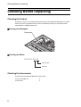
Checking Before Unpacking
Checking the Product
On delivery, be sure to check that the delivered product is the 3G3AX-DI Board that you ordered.
Should you find any problems with the product, immediately contact your nearest local sales
representative or OMRON sales office.
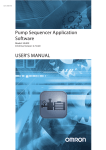
Checking the Nameplate
Nameplate
Checking the Model
3G3AX-DI01
Serial number
DI Board
Checking the Accessories
Accessories of the 3G3AX-DI Board are shown below.
•Fixing screws (M3 x 8)
•Ferrite cores
8
: 2
: 2
Revision History
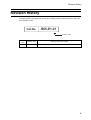
Revision History
A manual revision code appears as a suffix to the catalog number located at the lower left of the
front and back covers.
Cat.No.
I565-E1-01
Revision code
Revision
code
Revision date
01
April 2008
Changes and revision pages
First printing
9
About This Manual
About This Manual
This User's Manual is compiled chapter by chapter for user's convenience as follows:
Understanding the following configuration ensures more effective use of the product.
Chapter
10
Overview
Chapter 1
Overview
Describes the overview of this product.
Chapter 2
Design
Describes the mounting method of the product, terminal names,
wiring, and switch settings.
Chapter 3
Functions
Describes parameters for each function, type codes, and data input
timing chart.
Chapter 4
Maintenance
Operations
Describes precautions for switch settings and data input.
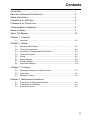
Contents
Introduction..............................................................................................1
Read and Understand This Manual.........................................................2
Safety Precautions ..................................................................................5
Precautions for Safe Use.........................................................................6
Precautions for Correct Use ....................................................................7
Checking Before Unpacking ....................................................................8
Revision History.......................................................................................9
About This Manual...................................................................................10
Chapter 1 Overview
1-1
Overview..................................................................................................1-1
Chapter 2 Design
2-1
2-2
2-3
2-4
2-5
2-6
2-7
2-8
Mounting the DI Board.............................................................................2-1
Terminal Arrangement .............................................................................2-2
Connection to Programmable Controllers................................................2-3
Terminal Functions ..................................................................................2-5
Wiring.......................................................................................................2-6
Switch Settings ........................................................................................2-8
Inverter Settings.......................................................................................2-9
Input Mode Settings.................................................................................2-10
Chapter 3 Functions
3-1
3-2
3-3
Parameter Description of Each Function .................................................3-1
Type Code ...............................................................................................3-5
Data Input Timing ....................................................................................3-6
Chapter 4 Maintenance Operations
4-1
4-2
4-3
Precautions for Setting the Switches .......................................................4-1
Precautions for Data Input .......................................................................4-2
Protective Function ..................................................................................4-3
11
Contents
12
Chapter 1
Overview
1-1 Overview ........................................................... 1-1
1-1 Overview
1Overview
1-1 Overview
The DI Board (3G3AX-DI) is an optional board for the 3G3RX Series Inverter.
With this board, you can digitally input the set frequency, acceleration time setting, deceleration time
setting, torque setting and position (orientation stop position) setting.
Overview
1
Note that the PG Board (3G3AX-PG) is required separately for position control through position setting inputs.
1-1
Chapter 2
Design
2-1
2-2
2-3
2-4
2-5
2-6
2-7
2-8
Mounting the DI Board..................................... 2-1
Terminal Arrangement..................................... 2-2
Connection to Programmable Controllers..... 2-3
Terminal Functions .......................................... 2-5
Wiring ................................................................ 2-6
Switch Settings ................................................ 2-8
Inverter Settings............................................... 2-9
Input Mode Settings......................................... 2-10
2-1 Mounting the DI Board
2Design
2-1
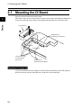
Mounting the DI Board
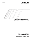
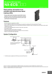
Securely mount the DI Board as shown below.
Place the four holes (in the corners) and the connector (on the back) of the DI Board on Board port 1
(or port 2) correctly with the two holes on the guideposts and the other two on the screw holes.
Design
2
The DI Board
Guideposts for
positioning the DI Board
Board port 1
Board port 2
Fixing screw holes
for the DI Board
(M3 screw)
Guideposts for
positioning the DI Board
To mount the DI Board, be sure to tightly fix it with the two provided fixing screws after putting in
place the connector securely. Otherwise, the Inverter will not operate properly.
2-1
2-2 Terminal Arrangement
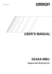
2-2 Terminal Arrangement
The terminal arrangement on the 3G3AX-DI is shown below.
2
Design
TM1
TM2
TM1
TM2
SEQ CMB D15 D14 D13 D12 D11 D10 D9
D8
D7
D6
D5
D4 D3
D2 D1
D0 STRB P24B PLCB CM1
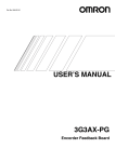
The standard terminal connection of the 3G3AX-DI is shown below.
3G3AX-DI
RY
SEQ (Sequence error signal output terminal)
CMB (Common terminal)
D15
D14
(Data input terminals)
D0
STRB (Strobe terminal)
(Short
circuit)
P24B
(Interface power terminals)
PLCB
CM1 (Common terminal)
Power is supplied to the input terminals (D0 to D15, STRB) when short-circuiting the P24B and
PLCB terminals for the sink logic interface, and short-circuiting the CM1 and PLCB terminals for the
source logic interface.
2-2
2-3 Connection to Programmable Controllers
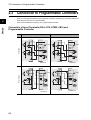
2-3
When connecting the DI Board to a programmable controller, there are four connection patterns for
input terminals, and two for output terminals.
Connect the DI Board according to your programmable controller.
2
Connection of Input Terminals (D0 to D15, STRB, CM1) and
Programmable Controller
When internal interface power supply is used
S
CM1
Sink logic
PLCB
When external power supply is used
S
CM1
24V DC
PLCB
P24B
P24B
D0
to D15
D0
to D15
STRB
24V DC
COM
STRB
3G3AX-DI
COM
COM
CM1
PLCB
24V DC
24V DC
CM1
PLCB
P24B
P24B
D0
to D15
D0
to D15
STRB
STRB
S
24V DC
S
3G3AX-DI
2-3
24V DC
COM
3G3AX-DI
Source logic
Design
Connection to Programmable Controllers
3G3AX-DI
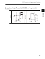
2-3 Connection to Programmable Controllers
Connection of Output Terminals (SEQ,CMB) and Programmable
Controller
2
CMB
Design
SEQ
COM
24V DC
COM
Source logic
Sink logic
24V DC
SEQ
CMB
3G3AX-DI
3G3AX-DI
2-4
2-4 Terminal Functions
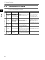
2-4 Terminal Functions
The terminal specifications list is shown below.
2
Input terminal
Output terminal
Power supply
Design
Terminal symbol
D0 to D15
Terminal name
Data input terminal
Electric characteristics
Photocoupler input (1 NO contact
signal)
Available at sink/source logic
Between (D0 to 15•STRB) and
CM1
Input ON voltage: 18 V DC
Input impedance: 4.7 kΩ
Max. allowable voltage: 27 V
DC
STRB
Strobe terminal
(Data retrieval command signal terminal)
SEQ
Sequence error signal
output terminal
(Data input error signal
output terminal)
Open collector output
Available at sink/source logic
Between SEQ and CMB
Voltage drop at power-ON: 4 V
max.
Max. allowable voltage: 27 V
DC
Max. allowable current: 50 mA
CMB
Common terminal for
sequence error signal
output
Common terminal only for sequence error signal output*1
−
P24B
Interface power terminal
24 V DC power supply for contact
input signal
(When the source logic is selected,
this terminal functions as the contact input common terminal.)
Max. allowable current: 90 mA
CM1
Interface power common terminal
Common terminal for interface
power, data input and strobe terminals
−
*1.Do not ground the terminal.
2-5
Functions
2-5 Wiring
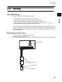
2-5 Wiring
2
Applicable Wiring
Be sure to observe the following wiring conditions:
For the signal line, use a shield wire of 0.5 mm2 or less.
Strip the signal line by 5 to 6 mm, and connect the exposed wire.
In the case of stranded wires, make sure that the wires are not unraveled.
Make sure that the maximum outside coating diameter of the signal line is 2.0 mm or less.
Do not exceed 20 m for the wiring length of the shield wire.
Design
•
•
•
•
•
The shield wire could be easily influenced by outside noise depending on the shielding method, resulting in an Inverter failure. Generally connect to the power supply ground of a signal line or to the
ground for shielding. (To connect to the ground, be careful of the ground cabling route, and avoid
multi-point grounding.)
Mounting the Ferrite Cores
The ferrite core mounting method is shown below.
Mount the two provided ferrite cores.
Connect the wire to the CM1 terminal of the 3G3AX-DI Board through the ferrite cores for shielding.
3G3AX-DI
Ferrite cores
Shield coating
Shield wire
2-6
2-5 Wiring
If the ferrite cores cover the shield coating, they fail to work effectively, causing the Inverter to malfunction. Be sure to fix the ferrite cores or take other appropriate measures so that they do not overlap the shield coating.
The shield wire connected to the terminal could become disconnected due to the weight of the ferrite
cores. Be sure to fix the ferrite cores or take other appropriate measures so that the shield wire does
not receive the weight of the ferrite cores.
Design
2
2-7
2-6 Switch Settings
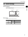
2-6 Switch Settings
2
Switch Arrangement
Rotary switch
CODE
TM1
DIP switch
TYPE
TM2
Default setting
The default settings (factory settings) are shown below.
Setting item
Switch No.
Default setting
DIP switch
TYPE
1
OFF (Binary input: BIN)
2
OFF (Batch input mode: PAC)
Rotary switch
CODE
−
0 (Set frequency: 0.01 Hz)
2-8
Design
The switch arrangement is shown below.
PAC, DIV, BIN, and BCD marked around the DIP switch (TYPE) indicate batch input, dividing input,
binary input, and BCD input, respectively.
2-7 Inverter Settings
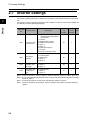
2-7 Inverter Settings
The Inverter (3G3RX) parameters related to the operation of the 3G3AX-DI Board are shown below.
For operation, refer to “Chapter 3 Operation” and ”Chapter 4 Functions” of the Inverter 3G3RX User’s Manual, and make appropriate settings.
Design
2
Function name
Data range
Default setting
(3G3RX)
Changes
during
operation
Unit
Frequency reference selection
00: Digital Operator (FREQ adjuster)
(Enabled when 3G3AX-OP01
is connected.)
01: Terminal
02: Digital Operator (F001)
03: ModBus communication
04: Option 1
05: Option 2
06: Pulse train frequency
07: Not used
10: Frequency operation result
02
×
−
b040
Torque limit
selection
00: Four-quadrant separate setting
01: Terminal switch
02: Analog input
03: Option 1
04: Option 2
00
×
−
P031
Acceleration/Deceleration time
input type
00: Digital Operator
01: Option 1
02: Option 2
00
×
−
P032
Orientation stop
position input
type
00: Digital Operator
01: Option 1
02: Option 2
00
×
−
Parameter
No.
A001
Note 1: To set the frequency, set the frequency reference selection (A001) to “Option” (04 or 05).
Note 2: To set the acceleration/deceleration time, set the acceleration/deceleration time input type
(P031) to “Option”.
Note 3: To set the torque limit, set the torque limit selection (b040) to “Option”.
Note 4: To set the orientation stop position, set the orientation stop position input type (P032) to
“Option”.
2-9
2-8 Input Mode Settings
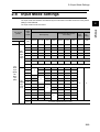
2-8 Input Mode Settings
The input mode and resolution are selected by the combination of the DIP switch and rotary switch
settings of the DI Board.
The input mode list is shown below.
Switch No.
1
2
Resolution setting
Rotary
switch
(CODE)
Setting
code
0.01 Hz
0
{
1
OFF:
Batch
input
mode
(PAC)
Acceleration/Deceleration
time setting
Set frequency
0.1 Hz
1 Hz
Rate
0.01 sec
0.1 sec
1 sec
Torque
limit
setting
Position
setting
1%
1 pulse
{
2
{
3
{
4
{
5
For factory adjustment (Do not set)
6
ON:
BCD
input
(BCD)
OFF:
Binary
input
(BIN)
{
7 to F
For factory adjustment (Do not set)
0
{
1
{
{
2
{
3
4
ON:
Dividing
input
mode
(DIV)
{
{
{
5
{
6
7
{
{
{
9
{
{
{
B
C to F
{
{
8
A
{
{
For factory adjustment (Do not set)
2-10
Design
DIP switch
(TYPE)
2
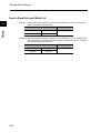
2-8 Input Mode Settings
How to Read the Input Mode List
Example 1. Switch setting when setting the frequency with a resolution of 1 Hz, via binary input
(BIN) in the batch input mode (PAC)
2
Design
TYPE
CODE
1
2
OFF: BIN
OFF: PAC
2
Example 2. Switch setting when setting the frequency with a resolution of 0.1 Hz, via BCD input,
and setting the acceleration/deceleration time with a resolution of 0.1 sec, via BCD input in the dividing input mode (DIV)
TYPE
2-11
CODE
1
2
ON: BCD
ON: DIV
4
Chapter 3
Functions
3-1 Parameter Description of Each Function....... 3-1
3-2 Type Code......................................................... 3-5
3-3 Data Input Timing............................................. 3-6
3-1 Parameter Description of Each Function
3Functions
3-1
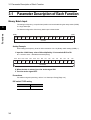
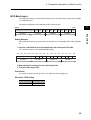
Parameter Description of Each Function
Binary Batch Input
The settings of frequency, torque limit and position can be selected using the rotary switch (CODE)
in a single data input.
3
Functions
The data bit configuration of the binary batch input is shown below.
(MSB)
(LSB)
D15 D14 D13 D12 D11 D10
D9
D8
D7
D6
D5
D4
D3
D2
D1
D0
Set data
Setting Example
When setting the frequency to 60 Hz with a resolution of 0.1 Hz (Rotary switch setting (CODE): 1)
1. Input the 16-bit binary value of 60 multiplied by 10 in terminals D15 to D0.
60 × 10 times = 600 → 0000001001011000 (binary)
D15 D14 D13 D12 D11 D10
0
0
0
0
0
0
D9
D8
D7
D6
D5
D4
D3
D2
D1
D0
1
0
0
1
0
1
1
0
0
0
16-bit data
2. When the data is entered, turn the strobe signal ON.
3. Turn the strobe signal OFF.
Precautions
For details on signal input timing, refer to "3-3 Data Input Timing"(Page 3-6).
DIP switch TYPE setting
3-1
1
2
OFF: BIN
OFF: PAC
3-1 Parameter Description of Each Function
BCD Batch Input
The settings of frequency, torque limit and position can be selected using the rotary switch (CODE)
in a single data input.
The data bit configuration of the BCD batch input is shown below.
(MSB)
3
(LSB)
D15 D14 D13 D12 D11 D10 D 9
D7
Set data 3
D6
D5
D4
D3
Set data 2
D2
D1
D0
Set data 1
Setting Example
When setting the frequency to 30.00 Hz with a resolution of 0.01 Hz (Rotary switch setting (CODE):
0)
1. Input the 16-bit BCD value of 30 multiplied by 100 in terminals D15 to D0.
30 × 100 times = 3000 → 0011000000000000 (binary)
D15 D14 D13 D12 D11 D10 D 9
0
0
1
1
0
Set data 4
0
0
Set data 3
D8
D7
D6
D5
D4
D3
D2
D1
D0
0
0
0
0
0
0
0
0
0
Set data 2
Set data 1
2. When the data is entered, turn the strobe signal ON.
3. Turn the strobe signal OFF.
Precautions
For details on signal input timing, refer to "3-3 Data Input Timing"(Page 3-6).
DIP switch TYPE setting
1
2
ON: BCD
OFF: PAC
3-2
Functions
Set data 4
D8
3-1 Parameter Description of Each Function
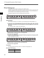
Binary Dividing Input
The set data can be changed in two data inputs for MSB and LSB.
In addition, changing the type code enables to change the settings of frequency, torque limit, acceleration/deceleration time, and position (For the type code, refer to "3-2 Type Code"(Page 3-5)).
The set resolution can be selected using the rotary switch (CODE).
3
The data bit configuration of the binary dividing input is shown below.
(MSB)
(LSB)
Functions
D15 D14 D13 D12 D11 D10 D 9
D8
D7
MSB or LSB type codes
D6
D5
D4
D3
D2
D1
D0
MSB 8-bit or LSB 8-bit set data
Setting Example
When setting the frequency to a resolution of 0.01 Hz (Rotary switch setting (CODE): 0,1,2)
1. Convert the value of 60 multiplied by 100 into the 16-bit binary value. Next, input the
MSB 8 bits in terminals D7 to D0, and input the set frequency MSB code in terminals
D15 to D8.
60 × 100 times = 6000 → 0001011101110000 (binary)
D15 D14 D13 D12 D11 D10 D 9
0
0
0
0
0
0
0
D8
D7
D6
D5
D4
D3
D2
D1
D0
0
0
0
0
1
0
1
1
1
Set frequency MSB codes
MSB 8-bit set data
2. When the data is entered, turn the strobe signal ON.
3. Turn the strobe signal OFF.
4. Input the rest of LSB 8 bits in terminals D7 to D0, and input the set frequency LSB
code in terminals D15 to D8.
D15 D14 D13 D12 D11 D10 D 9
0
0
0
0
0
0
0
Set frequency LSB codes
D8
D7
D6
D5
D4
D3
D2
D1
D0
1
0
1
1
1
0
0
0
0
LSB 8-bit set data
5. When the data is entered, turn the strobe signal ON.
6. Turn the strobe signal OFF.
Precautions
For details on signal input timing, refer to "3-3 Data Input Timing"(Page 3-6).
DIP switch TYPE setting
3-3
1
2
OFF: BIN
ON: DIV
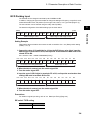
3-1 Parameter Description of Each Function
BCD Dividing Input
The set data can be changed in two data inputs for MSB and LSB.
In addition, changing the type code enables to change the settings of frequency, torque limit, acceleration/deceleration time, and position (For the type code, refer to "3-2 Type Code"(Page 3-5)).
The set resolution can be selected using the rotary switch (CODE).
3
The data bit configuration of the BCD dividing input is shown below.
(MSB)
(LSB)
D8
D7
MSB or LSB type codes
D6
D5
D4
D3
D2
D1
D0
MSB 2-digit or LSB 2-digit set data
Setting Example
When setting the acceleration time to 60.0 sec with a resolution of 0.1 sec (Rotary switch setting
(CODE): 1,4,7,A)
1. Convert the value of 60 multiplied by 10 into the BCD binary value. Next, input the
MSB 2 digits in terminals D7 to D0, and input the acceleration time MSB code in terminals D15 to D8.
60 × 10 times = 600 → 0000011000000000 (binary)
D15 D14 D13 D12 D11 D10 D 9
0
0
0
0
0
1
0
D8
D7
D6
D5
D4
D3
D2
D1
D0
0
0
0
0
0
0
1
1
0
Acceleration time setting MSB codes
MSB 2-digit set data
2. When the data is entered, turn the strobe signal ON.
3. Turn the strobe signal OFF.
4. Input the rest of LSB 2 digits in terminals D7 to D0, and input the acceleration time
setting LSB code in terminals D15 to D8.
D15 D14 D13 D12 D11 D10 D 9
0
0
0
0
0
1
0
Acceleration time setting LSB codes
D8
D7
D6
D5
D4
D3
D2
D1
D0
1
0
0
0
0
0
0
0
0
LSB 2-digit set data
5. When the data is entered, turn the strobe signal ON.
6. Turn the strobe signal OFF.
Precautions
For details on signal input timing, refer to "3-3 Data Input Timing"(Page 3-6).
DIP switch TYPE setting
1
2
ON: BCD
ON: DIV
3-4
Functions
D15 D14 D13 D12 D11 D10 D 9
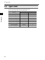
3-2 Type Code
3-2 Type Code
The type codes when the dividing input mode is set are shown below.
Be sure to input the type codes in the order of MSB to LSB.
Setting item
Functions
3
3-5
Type code (D15 to D8)
Binary
Hex
Set frequency (MSB)
00000000
0
Set frequency (LSB)
00000001
1
Torque limit setting (MSB)
00000010
2
Torque limit setting (LSB)
00000011
3
Acceleration time setting (MSB)
00000100
4
Acceleration time setting (LSB)
00000101
5
Deceleration time setting (MSB)
00000110
6
Deceleration time setting (LSB)
00000111
7
Position setting (MSB)
00001000
8
Position setting (LSB)
00001001
9
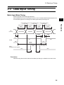
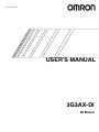
3-3 Data Input Timing
3-3 Data Input Timing
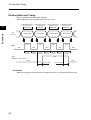
Batch Input Mode Timing
Retrieve the data at the strobe signal ON level.
Set the ON/OFF time for the strobe signal to 20 ms or more. If the data indefinite period exceeds 5 ms,
turn the strobe signal OFF according to the following batch data input timing chart.
Dn
(n=0-15)
Data indefinite period
5 ms or less
Data definite
period
20 ms or less
Data definite
period
20 ms or less
Data definite
period
20 ms or less
Data definite
period
20 ms or less
Normal data
Fault data
Normal data
Normal data
0 ms
or more
20 ms
or more
0 ms
or more
Functions
Data indefinite period Data indefinite period
5 ms or less
5 ms or less
ON
ON
STRB
OFF
OFF
20 ms
or more
20 ms
or more
ON
SEQ
(Sequence error output)
OFF
OFF
20 ms
or more
3
20 ms
or more
Precautions
Note that wrong data could be retrieved if the data input timing is not based on the above chart.
3-6
3-3 Data Input Timing
Dividing Data Input Timing
Retrieve the data at the strobe signal ON edge.
Set the ON/OFF time for the strobe signal to 20 ms or more.
Data definite period
20 ms or more
(MSB data)
Functions
3
Dn
(n=0-15)
Data definite period
20 ms or more
(LSB data)
Data definite period
20 ms or more
(MSB data)
Data definite period
20 ms or more
(LSB data)
Normal data
Fault data
Normal data
Normal data
0 ms or more
0 ms or more
0 ms or more
0 ms or more
ON
ON
ON
ON
STRB
OFF
OFF
20 ms
or more
20 ms
or more
OFF
20 ms
or more
20 ms
or more
SEQ
(Sequence error output)
OFF
20 ms
or more
20 ms
or more
OFF
20 ms
or more
ON
OFF
OFF
20 ms or less
20 ms or less
Precautions
Note that wrong data could be retrieved if the data input timing is not based on the above chart.
3-7
Chapter 4
Maintenance Operations
4-1 Precautions for Setting the Switches............. 4-1
4-2 Precautions for Data Input .............................. 4-2
4-3 Protective Function.......................................... 4-3
4-1 Precautions for Setting the Switches
4Maintenance Operations
4-1 Precautions for Setting the Switches
Precautions for setting the switches are shown below.
Shut off the Inverter power and set appropriate settings.
When the rotary switch CODE is set to (5,7 to F: for factory adjustment) in the batch input mode,
a sequence error is output just after power is supplied to the Inverter.
When the rotary switch CODE is set to (C to F: for factory adjustment) in the dividing input mode,
a sequence error is output just after power is supplied to the Inverter.
Maintenance Operations
4
4-1
4-2 Precautions for Data Input
4-2 Precautions for Data Input
Note the following items when inputting the data from the terminals of the 3G3AX-DI Board.
Each input can be set within the data range of the Inverter for each parameter.
If the data input is out of range, a sequence error will be output, and the data input will be disabled
(previous data retained).
Be sure to input type codes in the order of MSB to LSB in the dividing input mode.
If the LSB code is input first, a sequence error will be output, and the data input will be disabled
(previous data retained).
To reset the sequence error, input a correct data again, reset the Inverter, or shut off the power.
In the dividing input mode, if the two data inputs are correct, the sequence error will be reset just
after the second input.
The data input is disabled when the Inverter trips. Reset the Inverter and input again.
Do not set each command source of the Inverter (A001, P031, b040, P032) to “Option (1 or 2)”
for the port without the DI Board mounted. (Option 1 for Board port 1, 2 for Board port 2)
Do not mount two DI Boards simultaneously. Doing so may result in malfunction.
The set values just after each command source of the Inverter (A001, P031, b040, P032) is set
to “Option (1 or 2)” are shown below.
Set frequency
Acceleration/Deceleration time
Torque limit setting
Position setting
0.00[Hz]
(Set values of the Inverter)
0[%]
0[pulse]
To input the set frequency in “rate”, use the following procedure.
Setting example
When setting the frequency in 75% of the maximum frequency, input Iin is as follows:
Iin = 0.75 × M
0.75: Rate
M: Input data full scale
DIP switch TYPE
Input data full scale value (M)
BIN
65535
BCD
9999
Note that f Hz that is actually set is calculated from the following formula:
f
=
Iin
M
Fmax
Fmax: Max. frequency Hz
The value ignoring the digit less than 0.001 Hz is used as the set frequency.
4-2
Maintenance Operations
If a code other than the type code is input, a sequence error will be output
4
4-3 Protective Function
4-3 Protective Function
Optional Board Protective Function List
E6*.
(OP1-*) appears when the DI Board is mounted on Board port 1 (Digital Operator connecter
side) , and E7*.
(OP2-*) appears when it is mounted on Board port 2 (control circuit terminal block
side).
The following table shows the protective function and display on the Digital Operator when the DI
Board is mounted.
4
Maintenance Operations
Name
3G3AX-DI01
error
Description
Shuts off the output and displays an error if a timeout occurs in
the communication between the Inverter and the DI Board.
Display on Digital Operator
ek6k0.
ek7k0.
Note: Input mode is determined by the combination of the DIP and rotary switches settings. Check the settings
of the DIP and rotary switches on the DI Board for any abnormal operation.
4-3
Terms and Conditions of Sale
1. Offer; Acceptance. These terms and conditions (these "Terms") are deemed
part of all quotes, agreements, purchase orders, acknowledgments, price lists,
catalogs, manuals, brochures and other documents, whether electronic or in
writing, relating to the sale of products or services (collectively, the "Products")
by Omron Electronics LLC and its subsidiary companies (“Omron”). Omron
objects to any terms or conditions proposed in Buyer’s purchase order or other
documents which are inconsistent with, or in addition to, these Terms.
2. Prices; Payment Terms. All prices stated are current, subject to change without notice by Omron. Omron reserves the right to increase or decrease prices
on any unshipped portions of outstanding orders. Payments for Products are
due net 30 days unless otherwise stated in the invoice.
3. Discounts. Cash discounts, if any, will apply only on the net amount of invoices
sent to Buyer after deducting transportation charges, taxes and duties, and will
be allowed only if (i) the invoice is paid according to Omron’s payment terms
and (ii) Buyer has no past due amounts.
4. Interest. Omron, at its option, may charge Buyer 1-1/2% interest per month or
the maximum legal rate, whichever is less, on any balance not paid within the
stated terms.
5. Orders. Omron will accept no order less than $200 net billing.
6. Governmental Approvals. Buyer shall be responsible for, and shall bear all
costs involved in, obtaining any government approvals required for the importation or sale of the Products.
7. Taxes. All taxes, duties and other governmental charges (other than general
real property and income taxes), including any interest or penalties thereon,
imposed directly or indirectly on Omron or required to be collected directly or
indirectly by Omron for the manufacture, production, sale, delivery, importation, consumption or use of the Products sold hereunder (including customs
duties and sales, excise, use, turnover and license taxes) shall be charged to
and remitted by Buyer to Omron.
8. Financial. If the financial position of Buyer at any time becomes unsatisfactory
to Omron, Omron reserves the right to stop shipments or require satisfactory
security or payment in advance. If Buyer fails to make payment or otherwise
comply with these Terms or any related agreement, Omron may (without liability and in addition to other remedies) cancel any unshipped portion of Products sold hereunder and stop any Products in transit until Buyer pays all
amounts, including amounts payable hereunder, whether or not then due,
which are owing to it by Buyer. Buyer shall in any event remain liable for all
unpaid accounts.
9. Cancellation; Etc. Orders are not subject to rescheduling or cancellation
unless Buyer indemnifies Omron against all related costs or expenses.
10. Force Majeure. Omron shall not be liable for any delay or failure in delivery
resulting from causes beyond its control, including earthquakes, fires, floods,
strikes or other labor disputes, shortage of labor or materials, accidents to
machinery, acts of sabotage, riots, delay in or lack of transportation or the
requirements of any government authority.
11. Shipping; Delivery. Unless otherwise expressly agreed in writing by Omron:
a. Shipments shall be by a carrier selected by Omron; Omron will not drop ship
except in “break down” situations.
b. Such carrier shall act as the agent of Buyer and delivery to such carrier shall
constitute delivery to Buyer;
c. All sales and shipments of Products shall be FOB shipping point (unless otherwise stated in writing by Omron), at which point title and risk of loss shall
pass from Omron to Buyer; provided that Omron shall retain a security interest in the Products until the full purchase price is paid;
d. Delivery and shipping dates are estimates only; and
e. Omron will package Products as it deems proper for protection against normal handling and extra charges apply to special conditions.
12. Claims. Any claim by Buyer against Omron for shortage or damage to the
Products occurring before delivery to the carrier must be presented in writing
to Omron within 30 days of receipt of shipment and include the original transportation bill signed by the carrier noting that the carrier received the Products
from Omron in the condition claimed.
13. Warranties. (a) Exclusive Warranty. Omron’s exclusive warranty is that the
Products will be free from defects in materials and workmanship for a period of
twelve months from the date of sale by Omron (or such other period expressed
in writing by Omron). Omron disclaims all other warranties, express or implied.
(b) Limitations. OMRON MAKES NO WARRANTY OR REPRESENTATION,
EXPRESS OR IMPLIED, ABOUT NON-INFRINGEMENT, MERCHANTABIL-
14.
15.
16.
17.
18.
ITY OR FITNESS FOR A PARTICULAR PURPOSE OF THE PRODUCTS.
BUYER ACKNOWLEDGES THAT IT ALONE HAS DETERMINED THAT THE
PRODUCTS WILL SUITABLY MEET THE REQUIREMENTS OF THEIR
INTENDED USE. Omron further disclaims all warranties and responsibility of
any type for claims or expenses based on infringement by the Products or otherwise of any intellectual property right. (c) Buyer Remedy. Omron’s sole obligation hereunder shall be, at Omron’s election, to (i) replace (in the form
originally shipped with Buyer responsible for labor charges for removal or
replacement thereof) the non-complying Product, (ii) repair the non-complying
Product, or (iii) repay or credit Buyer an amount equal to the purchase price of
the non-complying Product; provided that in no event shall Omron be responsible for warranty, repair, indemnity or any other claims or expenses regarding
the Products unless Omron’s analysis confirms that the Products were properly handled, stored, installed and maintained and not subject to contamination, abuse, misuse or inappropriate modification. Return of any Products by
Buyer must be approved in writing by Omron before shipment. Omron Companies shall not be liable for the suitability or unsuitability or the results from the
use of Products in combination with any electrical or electronic components,
circuits, system assemblies or any other materials or substances or environments. Any advice, recommendations or information given orally or in writing,
are not to be construed as an amendment or addition to the above warranty.
See http://www.omron247.com or contact your Omron representative for published information.
Limitation on Liability; Etc. OMRON COMPANIES SHALL NOT BE LIABLE
FOR SPECIAL, INDIRECT, INCIDENTAL, OR CONSEQUENTIAL DAMAGES,
LOSS OF PROFITS OR PRODUCTION OR COMMERCIAL LOSS IN ANY
WAY CONNECTED WITH THE PRODUCTS, WHETHER SUCH CLAIM IS
BASED IN CONTRACT, WARRANTY, NEGLIGENCE OR STRICT LIABILITY.
Further, in no event shall liability of Omron Companies exceed the individual
price of the Product on which liability is asserted.
Indemnities. Buyer shall indemnify and hold harmless Omron Companies and
their employees from and against all liabilities, losses, claims, costs and
expenses (including attorney's fees and expenses) related to any claim, investigation, litigation or proceeding (whether or not Omron is a party) which arises
or is alleged to arise from Buyer's acts or omissions under these Terms or in
any way with respect to the Products. Without limiting the foregoing, Buyer (at
its own expense) shall indemnify and hold harmless Omron and defend or settle any action brought against such Companies to the extent based on a claim
that any Product made to Buyer specifications infringed intellectual property
rights of another party.
Property; Confidentiality. Any intellectual property in the Products is the exclusive property of Omron Companies and Buyer shall not attempt to duplicate it
in any way without the written permission of Omron. Notwithstanding any
charges to Buyer for engineering or tooling, all engineering and tooling shall
remain the exclusive property of Omron. All information and materials supplied
by Omron to Buyer relating to the Products are confidential and proprietary,
and Buyer shall limit distribution thereof to its trusted employees and strictly
prevent disclosure to any third party.
Export Controls. Buyer shall comply with all applicable laws, regulations and
licenses regarding (i) export of products or information; (iii) sale of products to
“forbidden” or other proscribed persons; and (ii) disclosure to non-citizens of
regulated technology or information.
Miscellaneous. (a) Waiver. No failure or delay by Omron in exercising any right
and no course of dealing between Buyer and Omron shall operate as a waiver
of rights by Omron. (b) Assignment. Buyer may not assign its rights hereunder
without Omron's written consent. (c) Law. These Terms are governed by the
law of the jurisdiction of the home office of the Omron company from which
Buyer is purchasing the Products (without regard to conflict of law principles). (d) Amendment. These Terms constitute the entire agreement between
Buyer and Omron relating to the Products, and no provision may be changed
or waived unless in writing signed by the parties. (e) Severability. If any provision hereof is rendered ineffective or invalid, such provision shall not invalidate
any other provision. (f) Setoff. Buyer shall have no right to set off any amounts
against the amount owing in respect of this invoice. (g) Definitions. As used
herein, “including” means “including without limitation”; and “Omron Companies” (or similar words) mean Omron Corporation and any direct or indirect
subsidiary or affiliate thereof.
Certain Precautions on Specifications and Use
1. Suitability of Use. Omron Companies shall not be responsible for conformity
with any standards, codes or regulations which apply to the combination of the
Product in the Buyer’s application or use of the Product. At Buyer’s request,
Omron will provide applicable third party certification documents identifying
ratings and limitations of use which apply to the Product. This information by
itself is not sufficient for a complete determination of the suitability of the Product in combination with the end product, machine, system, or other application
or use. Buyer shall be solely responsible for determining appropriateness of
the particular Product with respect to Buyer’s application, product or system.
Buyer shall take application responsibility in all cases but the following is a
non-exhaustive list of applications for which particular attention must be given:
(i) Outdoor use, uses involving potential chemical contamination or electrical
interference, or conditions or uses not described in this document.
(ii) Use in consumer products or any use in significant quantities.
(iii) Energy control systems, combustion systems, railroad systems, aviation
systems, medical equipment, amusement machines, vehicles, safety equipment, and installations subject to separate industry or government regulations.
(iv) Systems, machines and equipment that could present a risk to life or property. Please know and observe all prohibitions of use applicable to this Product.
NEVER USE THE PRODUCT FOR AN APPLICATION INVOLVING SERIOUS
RISK TO LIFE OR PROPERTY OR IN LARGE QUANTITIES WITHOUT
ENSURING THAT THE SYSTEM AS A WHOLE HAS BEEN DESIGNED TO
2.
3.
4.
5.
ADDRESS THE RISKS, AND THAT THE OMRON’S PRODUCT IS PROPERLY RATED AND INSTALLED FOR THE INTENDED USE WITHIN THE
OVERALL EQUIPMENT OR SYSTEM.
Programmable Products. Omron Companies shall not be responsible for the
user’s programming of a programmable Product, or any consequence thereof.
Performance Data. Data presented in Omron Company websites, catalogs
and other materials is provided as a guide for the user in determining suitability and does not constitute a warranty. It may represent the result of Omron’s
test conditions, and the user must correlate it to actual application requirements. Actual performance is subject to the Omron’s Warranty and Limitations
of Liability.
Change in Specifications. Product specifications and accessories may be
changed at any time based on improvements and other reasons. It is our practice to change part numbers when published ratings or features are changed,
or when significant construction changes are made. However, some specifications of the Product may be changed without any notice. When in doubt, special part numbers may be assigned to fix or establish key specifications for
your application. Please consult with your Omron’s representative at any time
to confirm actual specifications of purchased Product.
Errors and Omissions. Information presented by Omron Companies has been
checked and is believed to be accurate; however, no responsibility is assumed
for clerical, typographical or proofreading errors or omissions.
OMRON ELECTRONICS LLC • THE AMERICAS HEADQUARTERS
Schaumburg, IL USA • 847.843.7900 • 800.556.6766 • www.omron247.com
OMRON CANADA, INC. • HEAD OFFICE
OMRON ARGENTINA • SALES OFFICE
Toronto, ON, Canada • 416.286.6465 • 866.986.6766 • www.omron.ca
Cono Sur • 54.11.4787.1129
OMRON ELETRÔNICA DO BRASIL LTDA • HEAD OFFICE
OMRON CHILE • SALES OFFICE
São Paulo, SP, Brasil • 55.11.2101.6300 • www.omron.com.br
Santiago 56.2206.4592
OMRON ELECTRONICS MEXICO SA DE CV • HEAD OFFICE
OTHER OMRON LATIN AMERICA SALES
Apodaca, N.L. • 52.811.156.99.10 • [email protected]
56.2206.4592
I565-E1-01
Note: Specifications are subject to change.
© 2008 Omron Electronics LLC
Printed in U.S.A.