1
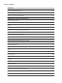
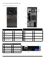
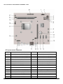
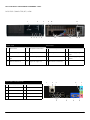
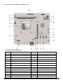
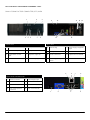
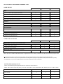
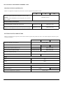
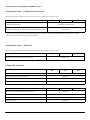
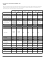
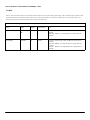
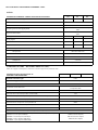
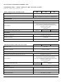
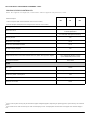
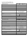
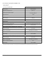
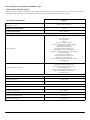
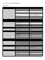
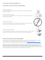
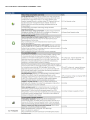
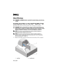
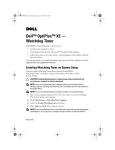
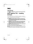
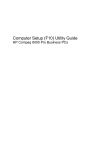
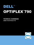
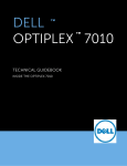
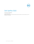
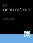
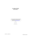
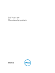
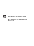
DELL
OPTIPLEX 390
TM
TM
TECHNICAL GUIDEBOOK—
INSIDE THE OPTIPLEX 390
TABLE OF CONTENTS
OVERVIEW
Mini Tower Computer (MT) View
3-4
Desktop Computer (DT) View
5-6
Small Form Factor Computer (SFF) View
7-8
MARKETING SYSTEM CON FIGURATIONS
Operating System, Chipset
9
Processor
10
Memory
11
Hard Drives, Removable Storage, System Expansion Slots
12
Graphics/Video Controller, External Ports/Connectors
13
Communications—Network Adapter (NIC), Wireless
14
Audio and Speakers, Keyboard and Mouse
14
Security, Software, Environmental, All-in-One Stands & Mounts, Service and Support
15
DETAILED ENGINEERING SPECIFICATIONS
System Dimensions (Physical)
16
System Expansion Slots
16
System Level Environmental and Operating Conditions
17
Power
18-19
Audio
20
Communications
20-25
Graphics/Video Controller
26-27
Hard Drives
28-31
Optical Drive
32-33
Media Card Reader
34
BIOS Defaults
35
Chassis Enclosure and Ventilation Requirements
36
Environmental Attributes
37
Acoustic Noise Emission Information
38-40
DELL™ OPTIPLEX™ 390 TECHNICAL GUIDEBOOK —FINAL
MI NI T OW E R C OMP UT E R (M T) VI EW
1
6
10
7
11
15
16
12
2
8
3
4
9
5
13
14
FRONT VIEW
BACK VIEW
1
Power Button, Power
Light
6
Optical Drive (optional)
10 Power Supply Diagnostic
Light
14
Expansion Card Slots(4)
2
Optical Drive Bay
(optional)
7
Optical Drive Eject Button
11 Power Supply Diagnostic
Button
15
Security Cable Slot
3
Microphone Connector
8
USB 2.0 Connectors (2)
12 Power Connectors
16
Padlock Ring
4 Headphone Connector
9
Drive Activity Light
5
13 Back Panel Connectors
Diagnostic Lights (4)
BACK PANEL CONNECTORS
1
1
Link Integrity Light
6
VGA Connector
2
Network Connector
7
Line-in Connector
3
Network Activity Light
8
Line-out Connector
4
USB Connectors (6)
9
Microphone Connector
5
HDMI Connector
2
8
3
4
5
6
7
9
3
DELL™ OPTIPLEX™ 390 TECHNICAL GUIDEBOOK —FINAL
MT System Board Components
Number
Name
Number
Name
1
Front IO connector (FRONTPANEL))
14
PCI-e 16x Connector (SLOT1)
2
Internal Speaker Connector (INT_SPKR)
15
System fan Connector (FAN_SYS2)
3
System fan Connector (FAN_SYS1)
16
P2 Power Connector(ATX12V)
4
SATA 1 Connector(SATA1)
17
CPU Socket Connector (U27CPU)
5
SATA 0 Connector(SATA0)
18
CPU fan Connector (FAN_CPU)
6
SATA 2 Connector(SATA2)
19
Memory Connector(DIMM1)
7
SATA 3 Connector(SATA3)
20
P1 power Connector (ATX)
8
Internal USB Connector (USBF1)
21
Power Switch Connector (PWRSW1)
9
Internal USB Connector (USBF1)
22
Memory Connector(DIMM2)
10
Internal Audio Connector (AUDIOF1)
23
Battery Connector (BT1)
11
PCI-e 1x Connector (SLOT4)
24
Intrusion Switch Connector (Intruder)
12
PCI-e 1x Connector (SLOT3)
25
KB/MS COM Connector (KBMSCOM1)
13
PCI-e 1x Connector (SLOT2)
4
DELL™ OPTIPLEX™ 390 TECHNICAL GUIDEBOOK —FINAL
D ES KT OP C O MPU T ER ( DT) VI EW
1
2
4
5
6
3
7
9
10
8
FRONT VIEW
11
12
13
14 15
BACK VIEW
1
Optical Drive
5
Microphone Connector
9 Padlock Ring
13
Expansion Card Slots(4)
2
Optical Drive Eject Button
6
Headphone Connector
10 Security Cable Slot
14
Power Supply Diagnostic
Light
3
Power Button, Power
Light
7
Drive Activity Light
11 Power Connectors
15
Power Supply Diagnostic
Button
4
USB Connectors (2)
8
Diagnostic Lights (4)
12 Back Panel Connectors
BACK PANEL CONNECTORS
1
1
Link Integrity Light
6
VGA Connector
2
Network Connector
7
Line-in Connector
3
Network Activity Light
8
Line-out Connector
4
USB Connectors (6)
9
Microphone Connector
5
HDMI Connector
2
8
3
4
5
6
7
9
5
DELL™ OPTIPLEX™ 390 TECHNICAL GUIDEBOOK —FINAL
DT System Board Components
Number
Name
Number
Name
1
Front IO connector (FRONTPANEL))
14
PCI-e 16x Connector (SLOT1)
2
Internal Speaker Connector (INT_SPKR)
15
System fan Connector (FAN_SYS2)
3
System fan Connector (FAN_SYS1)
16
P2 Power Connector(ATX12V)
4
SATA 1 Connector(SATA1)
17
CPU Socket Connector (U27CPU)
5
SATA 0 Connector(SATA0)
18
CPU fan Connector (FAN_CPU)
6
SATA 2 Connector(SATA2)
19
Memory Connector(DIMM1)
7
SATA 3 Connector(SATA3)
20
P1 power Connector (ATX)
8
Internal USB Connector (USBF1)
21
Power Switch Connector (PWRSW1)
9
Internal USB Connector (USBF1)
22
Memory Connector(DIMM2)
10
Internal Audio Connector (AUDIOF1)
23
Battery Connector (BT1)
11
PCI-e 1x Connector (SLOT4)
24
Intrusion Switch Connector (Intruder)
12
PCI-e 1x Connector (SLOT3)
25
KB/MS COM Connector (KBMSCOM1)
13
PCI-e 1x Connector (SLOT2)
6
DELL™ OPTIPLEX™ 390 TECHNICAL GUIDEBOOK —FINAL
S MA LL F O R M F A CT O R C O MP UT E R (S FF) VI E W
1
4
2
5
6
3
7
10
11
14
8
FRONT VIEW
12
13
15
BACK VIEW
9 Padlock Ring
13
Power Supply Diagnostic
Light
10 Security Cable Slot
14
Back Panel Connectors
Diagnostic Lights (4)
11 Power Connectors
15
Expansion Card Slots(2)
Drive Activity Light
12 Power Supply Diagnostic
Button
1
Optical Drive
5
Microphone Connector
2
Optical Drive Eject Button
6
Headphone Connector
3
Power Button, Power
Light
7
8
4 USB 2.0 Connectors (2)
9
5
6
7
8
BACK PANEL CONNECTORS
1
HDMI Connector
5
Link Integrity Light
2
VGA Connector
6
Network Connector
3
USB Connectors (6)
7
Network Activity Light
4
Line-in/Microphone
Connector
8
Line-out Connector
1
2
3
4
7
DELL™ OPTIPLEX™ 390 TECHNICAL GUIDEBOOK —FINAL
SFF System Board Components
Number
Name
Number
Name
1
P1 power Connector (ATX)
12
KB/MS COM Connector (KBMSCOM1)
2
System fan Connector (FAN_SYS)
13
Battery Connector (BT1)
3
Internal Speaker Connector (INT_SPKR)
14
P2 Power Connector(ATX12V)
4
Front IO connector (FRONTPANEL)
15
CPU Socket Connector (U27CPU)
5
Internal USB Connector (USBF1)
16
CPU fan Connector (FAN_CPU)
6
PCI-e 16x Connector (SLOT1)
17
Memory Connector(DIMM1)
7
PCI-e 1x Connector (SLOT2)
18
Memory Connector(DIMM2)
8
Internal Audio Connector (AUDIOF1)
19
Power Switch Connector (PWRSW1)
9
SATA 0 Connector(SATA0)
10
SATA 1 Connector (SATA1)
11
Intrusion Switch Connector (Intruder)
8
DELL™ OPTIPLEX™ 390 TECHNICAL GUIDEBOOK —FINAL
MARKETING SYSTEM CONFIGURATIONS
NOTE: Offerings may vary by country. For more information regarding the configuration of your computer, click
Start>Help and Support and select the option to view information about your computer.
OPER ATI N G S YS TEM
MT
Windows 7® operating system
Windows Vista® operating system
Windows XP® operating system
Other
DT
SFF
Microsoft® Windows 7® Home Basic SP1 (32 and 64 bit),
Microsoft® Windows 7® Home Premium SP1 (32 and 64 bit),
Microsoft® Windows 7® Professional SP1 (32 and 64 bit),
Microsoft® Windows 7® Ultimate SP1 (32 and 64 bit),
Windows Vista® Home Basic SP2 (32 bits),
Windows Vista® Business SP2 (32 and 64 bit),
Windows Vista® Ultimate SP2 (32 bit)
Basic Driver support only via Dell.com
FreeDOS for N-series
Ubuntu® Linux version 10.10 (China only)
OS Media Support (optional)
X
X
X
C HI PSE T
MT
Chipset
DT
SFF
Intel H61 Express Chipset
Non-volatile memory on chipset
BIOS Configuration SPI (Serial Peripheral Interface)
NIC EEPROM
32Mbit (4MB) located at SPI_FLASH on chipset
LOM configuration contained within SPI_FLASH – no dedicated
LOM EEPROM
9
DELL™ OPTIPLEX™ 390 TECHNICAL GUIDEBOOK —FINAL
PR O CE SS OR
NOTE: Global Standard Products (GSP) are a subset of Dell’s relationship products that are managed for availability and synchronized transitions on a worldwide basis. They ensure the same platform is available for purchase globally. This allows customers to
reduce the number of configurations managed on a worldwide basis, thereby reducing their costs. They also enable companies
to implement global IT standards by locking in specific product configurations worldwide. The following GSP processors identified below will be made available to Dell customers.
NOTE: Processor numbers are not a measure of performance. Processor availability subject to change and may vary by region/
country.
MT
DT
SFF
X-GSP
X-GSP
X-GSP
Intel® Core™ i3 2130 / 3.40GHz, 3M, VT-x, 65W
Available in Q4
2011
Available in Q4
2011
Available in Q4
2011
Intel® Core™ i3 2120 / 3.30GHz, 3M, VT-x, 65W
X
X
X
Intel® Core™ i3 2100 / 3.10GHz, 3M, VT-x, 65W
X
X
X
Intel® Pentium Dual Core™ G850 / 2.90GHz, 3M, VT-x, 65W
X
X
X
Intel® Pentium Dual Core™ G840 / 2.80GHz, 3M, VT-x, 65W
X
X
X
Intel® Pentium Dual Core™ G630 / 2.70GHz, 3M, VT-x, 65W
Available in Q4
2011
Available in Q4
2011
Available in Q4
2011
Intel® Pentium Dual Core™ G620 / 2.60GHz, 3M, VT-x, 65W
X
X
X
Available in Q4
2011
Available in Q4
2011
Available in Q4
2011
Available in Q4
2011
Available in Q4
2011
Available in Q4
2011
Intel® Quad Core™ i5 Processors
Intel® Core™ i5 2400 / 3.10GHz, 6M, VT-x, 95W
Intel® Dual Core™ i3 Processors
Intel® Pentium® Dual Core Processors
Intel® Celeron® Processors
Intel® Celeron Dual Core™ G530 / 2.40GHz, 2M, VT-x, 65W
Intel® Celeron Single Core™ G440 / 1.60GHz, 1M, VT-x, 65W
10
DELL™ OPTIPLEX™ 390 TECHNICAL GUIDEBOOK —FINAL
MEM OR Y
NOTE: Memory modules should be installed in pairs of matched memory size, speed, and technology. If the memory modules
are not installed in matched pairs, the computer will continue to operate, but with a slight reduction in performance. The entire
8GB memory range is available to 64-bit operating systems.
MT
Type: DDR3 Synch DRAM Non-ECC Memory
DIMM Slots
DT
SFF
1333MHz
2
2
2
Up to 4GB
Up to 4GB
Up to 4GB
Minimum Memory
1GB
1GB
1GB
Maximum System Memory
8GB1
8GB1
8GB1
8GB1 DDR3, 1333MHz, (2 DIMM)
X
X
X
4GB1 DDR3, 1333MHz, (1 DIMM)
X
X
X
3GB DDR3, 1333MHz, (2 DIMM)
X
X
X
2GB DDR3, 1333MHz, (1 DIMM)
X
X
X
1GB DDR3, 1333MHz, (1 DIMM)
X
X
X
DIMM Capacities
Memory configurations
1
The total amount of available memory will be less than 4GB. The amount less depends on the actual system configuration. To fully utilize 4GB or
more of memory requires a 64-bit enabled processor and 64-bit operating system.
11
DELL™ OPTIPLEX™ 390 TECHNICAL GUIDEBOOK —FINAL
HA R D DRI V ES
MT
DT
SFF
5.25-inch Optical Bay Supported (External)
2
1
1
Optical Drives Supported (maximum)
2
1
1 (slim-line)
Hard Drive Bay Supported (Internal)
2
1
1
Hard Drives Supported 3.5”(maximum)
2
1
1
4
4
2
1TB1 SATA 7200 RPM HDD
X
X
X
500GB1 SATA 7200 RPM HDD
X
X
X
320GB SATA 7200 RPM HDD
X
X
X
250GB1 SATA 7200 RPM HDD
X
X
X
MT
DT
SFF
DVD+/-RW2 SATA 1.5Gbit/s
X
X
X
DVD-ROM3 SATA 1.5Gbit/s
X
X
X
X
X
Bays:
Interface:
SATA 2.0
SATA 3.0 (chipset does not support)
3.5” Hard Drives:
1
R EMO V A BLE S TOR AG E
Optical Drive: (SFF require slim-line optical drive)
Media Card Reader: (requires slim line optical)
Dell 19 in 1 Media Card Reader
NOTE: Dell 19 in 1 Media Card Reader (MCR) is supported via a F5 to F3 bay converter on the MT and DT and may require a slim
1
For hard drives, GB means 1 billion bytes; actual capacity varies with preloaded material and operating environment and will be less.
Discs burned with this drive may not be compatible with some existing drives and players; using DVD+R media provides maximum compatibility.
3
DVD-ROM drives may have write-capable hardware that has been disabled via firmware modifications.
2
SY ST EM EX PA NSI ON S LO T S
NOTE: See Detailed Engineering Specifications for maximum card dimensions.
NOTE: Add in card location and priority: PCIe x16: GFX, USB 3.0, Serial, Parallel/Serial, NIC, Wireless; PCIe x1: USB 3.0, Serial,
MT
DT
SFF
PCIe x16 Slot
1
1
1
PCIe x1 Slot
3
3
1
Serial ATA (SATA) connectors
4
4
2
12
DELL™ OPTIPLEX™ 390 TECHNICAL GUIDEBOOK —FINAL
GR A P HI CS / VI DEO CO NTR OLL ER
NOTE: MT supports full height (FH) cards and DT and SFF supports low profile (LP) cards.
MT
DT
Intel HD Graphics [with Celeron/Pentium class CPU-GPU
combo]
Intel HD Graphics 2000[with iCore Dual/Quad core class CPUGPU combo]
SFF
Integrated on CPU
Enhanced Graphic/Video Options
1GB AMD RADEON HD 6450 with DP and DVI
Optional FH card
Optional LP card
512MB AMD RADEON HD 6350 with dual DVI or dual VGA
(adapters convert DMS-59 connector to dual DVI or dual VGA)
Optional FH card
Optional LP card
EX TER NA L POR TS / CO NN E CTO R S
NOTE: MT supports full height (FH) cards and DT and SFF supports low profile (LP) cards. See chassis diagrams section for port/
connector locations
MT
DT
USB 2.0 (1 internal on MT and DT)
Parallel and Serial port via optional PCIex1 card
2 Front, 6 Rear
Optional FH card
Optional LP card
Parallel port via optional PCIex1 card
Serial and PS/2 via optional dongle
Optional FH card
Network Connector (RJ-45)
USB 3.0 via optional PCIex1 card
SFF
Optional LP card
1 Rear
Optional FH card
Optional LP card
Video:
VGA
1 Rear
HDMI
1 Rear
Audio:
Line in for microphone
Line in for stereo
Line out for headphones or speakers
1 Front, 1 Rear
1 Rear
1 Front, 1 Rear
13
DELL™ OPTIPLEX™ 390 TECHNICAL GUIDEBOOK —FINAL
CO MM UNI C A TIO NS - NE TW OR K A DAP TE R ( NI C)
NOTE: MT supports full height (FH) cards and DT and SFF supports low profile (LP) cards.
MT
Integrated Realtek LOM
DT
SFF
Integrated on system board
Broadcom NetXtreme 10/100/1000 PCIe Gigabit Networking Card
Optional card
1
This term does not connote an actual operating speed of 1 Gb/sec. For high speed transmission, connection to a Gigabit
Ethernet server and network infrastructure is required.
CO MM UNI C A TIO NS – W I R EL ES S
NOTE: MT supports full height (FH) cards and DT and SFF supports low profile (LP) cards.
MT
Dell Wireless 1520 PCIe WLAN card (802.11n)
DT
SFF
Optional card
AU DIO A N D SP EA KER S
MT
Conexant CX20641 High Definition Audio Codec
DT
SFF
Integrated on system board
Internal Dell Business Audio Speaker
Optional
Dell AX210 2.0 Desktop Speakers
Optional
Dell AX510/AX510PA Flat Panel Soundbar Speakers
Optional
MT
DT
Dell USB Entry Keyboard with optional palmrest
Optional
Dell Multimedia Pro Keyboard
Optional
Dell USB Optical Mouse
Optional
Dell Laser Mouse
Optional
SFF
14
DELL™ OPTIPLEX™ 390 TECHNICAL GUIDEBOOK —FINAL
SE CURI T Y
MT
DT
Chassis Intrusion Switch
Optional
Chassis lock slot and loop support
Standard
Dell Data Protection | Hardware Encryption Engine
SFF
Optional. Available in Q3 2011
SOF T WAR E
MT
Dell Client Manager
DT
SFF
Available via Dell.com
Dell Data Protection | Access (DDPA)
Standard
EN VIR ON ME NT AL
NOTE: For more details on Dell Environmental features, please to go to Environmental Attributes section.
your specific region for availability.
Sustainable packaging
MT
DT
SFF
X
X
X
MultiPack packaging
See
Optional, US only
Energy Efficient Power Supply
Optional
ALL -I N -O NE S TA N DS AN D MO UN T S
MT
DT
Small Form Factor AIO Stand
SFF
Optional
SER VI CE A N D SU PP O R T
NOTE: For more details on Dell Service Plans please to go to: www.dell.com/service/service_plans
MT
DT
3 Year Warranty1 Next Business Day On-site2 (3-3-3)
Standard
ProSupport
Optional
SFF
1
For a copy of our guarantees or limited warranties, please write Dell USA L.P., Attn: Warranties, One Dell Way, Round Rock, TX 78682. For more
information, visit www.dell.com/warranty.
2
Service may be provided by third-party. Technician will be dispatched if necessary following phone-based troubleshooting. Subject to parts
availability, geographical restrictions and terms of service contract. Service timing dependent upon time of day call placed to Dell. U.S. only.
15
DELL™ OPTIPLEX™ 390 TECHNICAL GUIDEBOOK —FINAL
DETAILED ENGINEERING SPECIFICATIONS
SY ST EM DIM EN SI O NS (P H YS I CAL)
NOTE: System Weight and Shipping Weight is based on a typical configuration and may vary based on PC configuration. A typical configuration
includes: integrated graphics, one hard drive, one optical drive.
MT
DT
SFF
26.27
15.06
8.38
19.55 / 8.87
16.67 / 7.56
12.57 / 5.70
Height (inches/centimeters)
14.17 / 36
14.17 / 36
11.42 / 29
Width (inches/centimeters)
6.89 / 17.5
4.02 / 10.2
3.65 / 9.26
Depth (inches/centimeters)
16.42 / 41.7
16.14 / 41
12.28/31.2
23.45 / 10.64
20.03 / 9.09
15.2 / 6.89
Height (inches/centimeters)
21.31/54.13
21.31 / 54.13
19.25/48.90
Width (inches/centimeters)
18.75/47.63
18.75/47.63
15.81/40.16
Depth (inches/centimeters)
14.09 / 35.79
10.84/27.53
10.19/25.88
MT
DT
SFF
1
1
1
Height (inches/centimeters)
4.376 / 11.115
2.731 /6.89
2.731 /6.89
Length (inches/centimeters)
7.4 / 24.13*
6.6 /16.765
6.6/16.765
75W
25W
25W
3
3
1
Height (inches/centimeters)
4.376 / 11.115
2.731 / 6.89
2.731 / 6.89
Length (inches/centimeters)
7.4 / 24.13*
6.6 /16.765
6.6 /16.765
25W
10W
10W
Chassis Volume (liters)
Chassis Weight (pounds/kilograms)
Chassis Dimensions: (HxWxD)
Shipping Weight (pounds/kilograms - includes packaging materials)
Packaging Parameters (HxWxD)
SY ST EM EX PA NSI ON S LO T S
PCIe x16 Slots (Voltage supported 3.3V/12V)
Maximum Wattage
PCIe x1 Slots (Voltage supported 3.3V/12V)
Maximum Wattage
* Card length can be longer than standard Half-Length Card but cannot be a Full-Length Card.
16
DELL™ OPTIPLEX™ 390 TECHNICAL GUIDEBOOK —FINAL
SY ST EM LE V EL EN VI R ON M EN TA L AN D O PE RATI N G C ON DI TIO NS
MT
DT
SFF
Temperature
Operating
10° to 35° C (50° to 95° F)
Non-Operating (Storage)
-40° to 65° C (-40° to 149° F)
Relative Humidity
20% to 80% (non-condensing)
Maximum vibration
Operating
Non-Operating
0.25 G at 3 to 200 Hz at 0.5 octave/min
0.5 G at 3 to 200 Hz at 1 octave/min
Maximum Shock
Operating
Non-Operating
Bottom half-sine pulse with a change in
velocity of 50.8 cm/sec (20 inches/sec)
27-G faired square wave with a velocity
change of 508 cm/sec (200 inches/sec)
Maximum Altitude
Operating
Non-Operating
–15.2 to 3048 m (–50 to 10,000 ft)
–15.2 to 10,668 m (–50 to 35,000 ft)
17
DELL™ OPTIPLEX™ 390 TECHNICAL GUIDEBOOK —FINAL
PO WER
NOTE: These form factors utilize a more efficient Active Power Factor Correction (APFC) power supply. Dell recommends only Universal Power
Supplies (UPS) based on Sine Wave output for APFC PSUs, not an approximation of a Sine Wave, Square Wave, or quasi-Square Wave. If you
have questions, please contact the manufacture to confirm the output type.
MT
APFC
DT
EPA
265W High
Efficiency
APFC
265W
AC input Voltage Range
90 – 264Vac
90 – 264Vac
90 – 264Vac
90 – 264Vac
90 – 264Vac
90 – 264Vac
AC input current (low ac
range/high AC range)
5.0A / 2.5A
5.0A / 2.5A
4.4A / 2.2A
4.4A / 2.2A
4.0A / 2.0A
4.0A / 2.0A
AC input Frequency
47HZ/63HZ
47HZ/63HZ
47HZ/63HZ
47HZ/63HZ
47HZ/63HZ
47HZ/63HZ
AC holdup time (80% load)
16MSEC
16MSEC
16MSEC
16MSEC
16MSEC
16MSEC
87 – 90 –
87% @ 20 –
50 – 100%
load
Average Efficiency (Energy
Star 5.0 Compliant)
65%
240W
SFF
APFC
EPA
240W High
Efficiency
Power Supply Wattage
Typical Efficiency (Active
PFC)
DC parameters
+3.3v output
+5.0v output
250W
EPA
250W High
Efficiency
87 – 90 –
87% @ 20 –
50 – 100%
load
65%
87 – 90 –
87% @ 20 –
50 – 100%
load
65%
10.0A
13A
10.0A
13A
7.0 A
15A
7.0 A
15A
3.5A
11A
3.5A
11A
12VA/17A;
12VB/9A
12VA/17A;
12VB/9A
17.8A
17.8A
17A
17A
4.0A
0.5A
265W
4.0A
0.5A
265W
4.0A
0.5A
255W
4.0A
0.5A
255W
4.0A
0.5A
235W
4.0A
0.5A
235W
90W
90W
90W
90W
60W
60W
240W
240W
N/A
N/A
N/A
N/A
BTUs/h (based on PSU
max wattage)
904 BTU
904 BTU
853 BTU
853 BTU
819 BTU
819 BTU
Power Supply Fan
80*25mm
80*25mm
80*20/25mm
80*20/25mm
60*25mm
60*25mm
Yes
Yes
Yes
Yes
Yes
Yes
Yes
Yes
Yes
Yes
Yes
Yes
No
Yes
No
Yes
No
Yes
Yes
Yes
Yes
Yes
Yes
Yes
+12.0v output
+5.0v auxiliary output
-12.0v output
Max total power
Max combined +3.3v /
+5.0v power
Max combined 12.0v
power (note: only if more
than one 12v rail)
Compliance:
1watt requirement
Blue Angel Compliant
Climate Savers / 80Plus
Compliant
FEMP (CECP) Standby
Power Compliant
18
DELL™ OPTIPLEX™ 390 TECHNICAL GUIDEBOOK —FINAL
PO WER
NOTE: These form factors utilize a more efficient Active Power Factor Correction (APFC) power supply. Dell recommends only Universal Power
Supplies (UPS) based on Sine Wave output for APFC PSUs, not an approximation of a Sine Wave, Square Wave, or quasi-Square Wave. If you
have questions, please contact the manufacture to confirm the output type.
3.0v CMOS battery (Type and estimated battery life)
Brand
Type
Voltage
Composition
Life
JHT
CR-2302L/
BE
3V
Lithium
Continuous Discharge Under 15 kΩ Load to 2.0V EndVoltage.
20℃±2℃.940Hrs. or Longer.910Hrs.or Longer after 12
months.
MITSUBISHI
CR2302
3V
Lithium
Continuous Discharge Under 15 kΩ Load to 2.0V EndVoltage.
20℃±2℃.940Hrs. or Longer.910Hrs.or Longer after 12
months.
0℃±2℃. 850Hrs. or Longer.820Hrs.or Longer after 12
months.
19
DELL™ OPTIPLEX™ 390 TECHNICAL GUIDEBOOK —FINAL
AU DIO
INTEGRATED CONEXANT CX20641 HIGH DEFINITION AUDIO
High Definition Stereo support
MT
DT
SFF
X
X
X
Number of channels
2
Number of Bits / Audio resolution
Sampling rate (recording/playback)
Signal to Noise Ratio
16, 20, and 24-bit resolution
Support 44.1K/48K/96K/192 kHz sample
rates
98 dB DAC outputs, 90 dB for ADC inputs
Analog Audio
X
X
X
Dolby Digital
THX
Digital out (S/PDIF)
Audio Jack Impedance
Microphone
40K ohm~60K ohm
Line-In
40K ohm~60K ohm
Line-Out
100~150 ohm
Headphone
1~4 ohm
Internal Speaker Power Rating
2Watt (peak) / 1Watt (average)
CO MM UNI C A TIO NS - NE T W OR K A DAP TE R ( NI C)
NOTE: MT supports full height (FH) cards and DT and SFF supports low profile (LP) cards.
INTEGRATED REALTEK® RTL8111E-VL
ETHERNET LAN 10/100/1000
External Connector Type
Data Rates supported
MT
DT
SFF
RJ45
10/100/1000 Mbps
Controller Details
Controller bus architecture
PCIe-based interface for S0 state, SMBus for Sx
low power state
Integrated memory
N/A
Data transfer mode (example Bus-Master DMA)
N/A
Power consumption (full operation per data rate connection speed)
448.8mW (Max.)
Power consumption (standby operation)
389.4mW (Max.)
IEEE standards compliance (example 802.1P)
Hardware Certifications (example FCC, B, GS mark…)
Boot ROM Support
802.3
N/A
EEPROM (located in SPI)
Network Transfer Mode (example Full Duplex, Half Duplex)
Network Transfer Rate (example 10BASE-T (half-duplex) 10 Mbps
10BASE-T (full-duplex) 20 Mbps
100BASE-TX (half-duplex) 100 Mbps
100BASE-TX (full-duplex) 200 Mbps
1000BASE-T (full-duplex) 2000 Mbps
10 Mb (full/half-duplex)
100 Mb (full/half-duplex)
1000 Mb (full-duplex)
20
DELL™ OPTIPLEX™ 390 TECHNICAL GUIDEBOOK —FINAL
CO MM UNI C A TIO NS - NE T W OR K A DAP TE R ( NI C) ( CO NT .)
INTEGRATED REALTEK® RTL8111E-VL
ETHERNET LAN 10/100/1000
MT
DT
SFF
Environmental
Operating temperature
0° C to 70° C (32° F to 158° F)
Operating humidity
20% to 80% (non-condensing)
Operating System Driver Support
Windows 7 32/64, Windows XP 32/64, Vista
32/64
Manageability (examples WOL, PXE)
WOL, PXE 2.1
1
This term does not connote an actual operating speed of 1 Gb/sec. For high speed transmission, connection to a Gigabit Ethernet server and
network infrastructure is required.
CO MM UNI C A TIO NS – I N T E GR A TE D L AN
NOTE: MT supports full height (FH) cards and DT and SFF supports low profile (LP) cards.
Broadcom NetXtreme 10/100/1000 PCIe Gigabit1 Networking Card
Connector Type
Data Rates supported
MT
DT
SFF
RJ45
10/100/1000 Mbps Half/Full duplex
Controller Details
Controller bus architecture (example PCIe 1.0a x1)
Integrated memory
Data transfer mode (example Bus-Master DMA)
Power consumption (full operation per data rate connection speed)
Power consumption (standby operation)
IEEE standards compliance (example 802.1P)
Hardware Certifications (example FCC, B, GS mark…)
Boot ROM Support
PCIe c1.0a x1
64KBytes RX, 8KBytes TX
Bus-Master DMA
2.84W (860mA @ +3.3V)
Less than 300mW
802.3, 802.2, 802.3x, 802.1p
FCC B, VCCI B, CE
No
Network Transfer Mode (example Full Duplex, Half Duplex)
Network Transfer Rate (example 10BASE-T (half-duplex) 10 Mbps
10BASE-T (full-duplex) 20 Mbps
100BASE-TX (half-duplex) 100 Mbps
100BASE-TX (full-duplex) 200 Mbps
1000BASE-T (full-duplex) 2000 Mbps
10BASE-T (full-duplex) 20 Mbps Max*
100BASE-TX (half-duplex) 100 Mbps
Max*
100BASE-TX (full-duplex) 200 MbpsMax*
1000BASE-T (full-duplex) 2000 Mbps
Max*
* Depends on the system environment.
1
This term does not connote an actual operating speed of 1 Gb/sec. For high speed transmission, connection to a Gigabit Ethernet server and
network infrastructure is required.
21
DELL™ OPTIPLEX™ 390 TECHNICAL GUIDEBOOK —FINAL
CO MM UNI C A TIO NS – I N T E GR A TE D L AN ( C ON T.)
BROADCOM NETXTREME 10/100/1000
PCIE GIGABIT1 NETWORKING CARD (CONT.)
MT
DT
SFF
Environmental
Operating temperature
0° C to 55° C (32° F - 131° F)
Operating humidity
5% ~ 85% (non-condensing)
Operating System Driver Support
Manageability (examples WOL, PXE)
Management Capabilities Alerting (example ASF 2.0)
1
Windows® 7, Windows® XP, Windows
Vista® Ultimate, Windows Vista® Business 32 bit/64 bit, Windows Vista Home
Basic, Linux
WOL, PXE2.1, ACPI
None
This term does not connote an actual operating speed of 1 Gb/sec. For high speed transmission, connection to a Gigabit Ethernet server and
22
DELL™ OPTIPLEX™ 390 TECHNICAL GUIDEBOOK —FINAL
CO MM UNI C A TIO NS – W I R EL ES S
DELL WIRELESS 1520 PCIE WLAN CARD (MT, DT, SFF) 802.11N
MT
External Connector Type
DT
SFF
Custom WLAN Antenna Connector
Controller Details
Controller bus architecture
Electrically compatible with the PCI Express Base
Specification v1.1 (x1 lane) and PCIe v1.0a.
WLAN standards supported
802.11a, 802.11b, 802.11g, 802.11n
802.11b Data Rates supported
11, 5.5, 2, 1 Mbps
802.11a Data Rates supported
54, 48, 36, 24, 18, 12, 9, 6 Mbps
802.11g Data Rates supported
54, 48, 36, 24, 18, 12, 9, 6 Mbps
802.11n Data Rates supported
300, 270, 243, 240, 180, 150, 144, 135, 130, 120, 117,
115.5, 90, 86.667, 72.2, 65, 60, 57.8, 45, 43.3, 30, 28.9,
21.7, 15, 14.4, 7.2 Mbps
WEP 64-bit and 128-bit,
TKIP, AES-CCMP 128-bit
Encryption
Operating temperature
0 to +70 °C
Operating humidity
Operating System Driver Support
Max Operating Humidity
85 %
Windows 7 32/64, Windows XP 32/64, Vista 32/64
C O MM U NI C ATI O NS – US B 3 . 0 A D D - I N C A R D
NOTE: MT supports full height (FH) cards and DT and SFF supports low profile (LP) cards.
USB 3.0 PORT PCIE ADD-IN CARD
MT
Connector Type
DT
SFF
PCI Express Gen. 2.0 X1
Controller Details
Controller bus architecture (example PCIe 1.0a x1)
PCI Express one lane (x1)
Chipset
NEC µPD720200
IO Ports
2 * USB3.0 port
Power Consumption
Under 30 mA
Connector
Full height USB3.0 add-in card
Half height USB3.0 add-in card
OS Support
USB 3.0 A Type
Optional
Optional
Win XP, Win Vista and Win 7
23
DELL™ OPTIPLEX™ 390 TECHNICAL GUIDEBOOK —FINAL
CO MM UNI C A TIO NS – SE R I AL / PAR ALLE L P ORT P CI E AD D -I N C A RD
NOTE: MT supports full height (FH) card.
SERIAL / PARALLEL PORT PCIE ADD-IN CARD
MT
Connector Type
Data Rates supported
DT
SFF
RS-232 and IEEE1284
50bps ~115.2Kbps(Serial)&Maximum 1.8MBp(Parallel)
Controller Details
Controller bus architecture (example PCIe 1.0a x1)
Driver Support
Full height Serial / Parallel add-in card
PCI Express one lane (x1)
Microsoft Client XP/Vista/7 (X86/X64)
Microsoft Server 2000/2003/2008 (X86/X64)
Microsoft Embedded XP Embedded/POS Ready 2009/
Embedded System 2009
Linux Linux 2.4.x/2.6.x
DOS DOS
Optional
Environment
Operation Temperature
0 to 60°C (32 to 140°F)
Operation Humidity
5 to 95% RH
Storage Temperature
LOW PROFILE PARALLEL PORT PCIE ADD-IN CARD
Connector Type
Data Rates supported
-20 to 85°C (-4 to 185°F)
MT
DT
SFF
IEEE1284
Maximum 1.8MBp
Controller Details
Controller bus architecture (example PCIe 1.0a x1)
Driver Support
Low Profile Parallel add-in card
PCI Express one lane (x1)
Microsoft Client XP/Vista/7 (X86/X64)
Microsoft Server 2000/2003/2008 (X86/X64)
Microsoft Embedded XP Embedded/POS Ready 2009/
Embedded System 2009
Linux Linux 2.4.x/2.6.x
DOS DOS
Optional
Environment
Operation Temperature
Operation Humidity
Storage Temperature
0 to 60°C (32 to 140°F)
5 to 95% RH
-20 to 85°C (-4 to 185°F)
24
DELL™ OPTIPLEX™ 390 TECHNICAL GUIDEBOOK —FINAL
CO MM UNI C A TIO NS — PS 2/ S ER I AL A D D IN D ON GLE
NOTE: MT supports full height (FH) dongle and DT and SFF supports low profile (LP) dongle.
PS2/SERIAL ADD IN DONGLE
MT
DT
Connector type
SFF
RS232 and PS2
Controller Details
Interface type
24 pins header connect to MB directly
IO Ports
Full height PS2/Serial add in dongle
Half height PS2/Serial add in dongle
1 Serial, 2 PS2
Optional
Optional
Environment
Operation Temperature
0° C to 70° C (32° F to 158° F)
Operation Humidity
20% to 80% (non-condensing)
Storage Temperature
-20 to 85°C (-4 to 185°F)
25
DELL™ OPTIPLEX™ 390 TECHNICAL GUIDEBOOK —FINAL
GR A P HI CS / VI DEO CO NTR OLL ER
NOTE: MT supports full height (FH) cards and DT and SFF supports low profile (LP) cards.
Onboard Graphics.
1. Intel HD Graphics [with Celeron/Pentium class CPU-GPU combo]
MT
DT
SFF
2. Intel HD Graphics 2000 [with iCore Dual/Quad core class CPU-GPU combo]
Bus Type
GPU core clock
Frame Buffer Memory (onboard and shared) Size and Speed
Overlay Planes
Integrated
Gen6 Core Intel® HD Graphics /HD Graphics 2000 @ 850MHz
Depends on available system memory (Up
to 1.7GB with 4GB system Memory)
Yes
Maximum Color Depth
32 bit
Maximum Vertical Refresh Rate
75 Hz
Multiple Display Support
Operating Systems Graphics/ Video API Support
Supported Resolutions and Max Refresh Rates (Hz) (Note: Analog and/or digital)
External Connectors
Yes
OpenGL 3.0/DirectX 10.1
Up to 1920x1200 @ 60Hz (HDMI)
Up to 2048x1536 @ 75Hz (VGA)
VGA, HDMI
HDMI
Bus Type
DDPD
Maximum supported resolution
Up to 1920x1200 @ 60Hz
Maximum power consumption
N/A
Audio Support
External connectors
Yes (Only for native HDMI Output)
HDMI
1
Up to 1.7 GB of system memory may be allocated to support integrated graphics, depending on operating system, system memory size and other
factors.
2
DVI and VGA can be used concurrently for multi-monitor display in DOS. The DisplayPort controller does not support multi-monitor display in
DOS
26
DELL™ OPTIPLEX™ 390 TECHNICAL GUIDEBOOK —FINAL
GR A PH IC S/V ID E O C O NTR O L LE R (C O N T.)
1GB AMD RADEON™ HD6450
MT
DT
Bus Type (example integrated or PCIe x16)
PCIEx16
GPU core clock
625Mhz
Frame Buffer Memory (onboard and shared) Size and Speed
800Mhz
Maximum power consumption
20W
Overlay Planes
Yes
Maximum Color Depth
32-bit
Maximum Vertical Refresh Rate
85Hz
Multiple Display Support
Yes
Operating Systems Graphics/ Video API Support
Supported Resolutions and Max Refresh Rates (Hz) (Note: Analog and/or digital)
D3D and OpenGL
Dual-Link DVI Max: 2560 x 1600/32bpp @ 75Hz
DispalyPort Max: 2560 x 1600/32bpp @ 75Hz
VGA Max : 1920x1440/32bpp @ 75Hz
Min : 640x480/8bpp @ 60Hz
External connectors
Audio Support
Dimensions of full height card inches/centimeters (L x H)
SFF
1 DVI-I and 1 DP or 1 VGA + 1 DP
Yes (For native DP). Able to support audio for DP to
HDMI dongle that supports audio pass through.
6.6 x 4.7 /
16.764 x 12.0
6.6 x 3.35 / 16.764 x 8.5
Dimensions of low profile card inches/centimeters (L x H)
Environmental Operating Conditions (Non-Condensing):
Operating Temperature Range
10°-50° C
Relative Humidity Range
5-90% RH
Altitude Range
512MB AMD RADEON™ HD6350
0-20,000 ft.
MT
DT
Bus Type (example integrated or PCIe x16)
PCIEx16
GPU core clock
650Mhz
Frame Buffer Memory (onboard and shared) Size and Speed
800Mhz
Maximum power consumption
20W
Overlay Planes
Yes
Maximum Color Depth
32-bit
Maximum Vertical Refresh Rate
85Hz
Multiple Display Support
Yes
Operating Systems Graphics/ Video API Support
Supported Resolutions and Max Refresh Rates (Hz) (Note: Analog and/or digital)
D3D and OpenGL
DVI Max : 1920x1200/32bpp @ 75Hz
VGA Max: 1920x1440/32bpp @ 75Hz
Min : 640x480/8bpp @ 60Hz
External connectors
1 DMS59 (DVI x2 or VGA x2)
Audio Support
Dimensions of full height card inches/centimeters (L x H)
Dimensions of low profile card inches/centimeters (L x H)
SFF
No
6.6 x 2.731 /
16.764 x
6.936
6.6 x 2.731 / 16.764 x 6.936
Environmental Operating Conditions (Non-Condensing):
Operating Temperature Range
10°-50° C
Relative Humidity Range
5-90% RH
Altitude Range
0-20,000 ft.
27
DELL™ OPTIPLEX™ 390 TECHNICAL GUIDEBOOK —FINAL
HA RD DRI V ES 1
3.5” 1TB SATA 7200 RPM HDD
Capacity (bytes)
Dimensions inches (W x D x H)
Interface type and Maximum speed
1,000,204,886,016
5.87 x 4 x 1
Up to 6Gb/s (SATA 3.0)
Up to 3Gb/s (SATA 2.0)
Internal buffer size
32 MB
Average Seek Time
8.5 ms
Rotational Speed
Logical Blocks
7200 rpm
1,953,525,168
Power Source
Power Consumption (reference only)
Spin Up Current (reference only)
Idle 5.0W, Active 10.0W(running IOmeter utility)
5V (1A) ,12V (2A)
Environmental Operating Conditions (Non-Condensing):
Temperature Range
Relative Humidity Range
Maximum Wet Bulb Temperature
Altitude Range
50C to 600C
20% to 80% non-condensing
290C
-50 ft to 10000 ft
Environmental Non-Operating Conditions (Non-Condensing):
Temperature Range
Relative Humidity Range
Maximum Wet Bulb Temperature
Altitude Range
1
-400C to 650C
10% to 90% non-condensing
380C
-50 ft to 35000 ft
For hard drives, GB means 1 billion bytes ; actual capacity varies with preloaded material and operating environment and will be less.
28
DELL™ OPTIPLEX™ 390 TECHNICAL GUIDEBOOK —FINAL
HA RD DRI V ES 1 ( CO NT .)
3.5” 500GB SATA 7200 RPM HDD
Capacity (bytes)
Dimensions inches (W x D x H)
Interface type and Maximum speed
500,107,862,016
5.87 x 4 x 1
Up to 6Gb/s (SATA 3.0)
Up to 3Gb/s (SATA 2.0)
Internal buffer size
16 MB
Average Seek Time
8.5 ms
Rotational Speed
Logical Blocks
7200 rpm
976,773,168
Power Source
Power Consumption (reference only)
Spin Up Current (reference only)
Idle 5.0W, Active 10.0W(running IOmeter utility)
5V (1A) ,12V (2A)
Environmental Operating Conditions (Non-Condensing):
Temperature Range
Relative Humidity Range
Maximum Wet Bulb Temperature
Altitude Range
50C to 600C
20% to 80% non-condensing
290C
-50 ft to 10000 ft
Environmental Non-Operating Conditions (Non-Condensing):
Temperature Range
Relative Humidity Range
Maximum Wet Bulb Temperature
Altitude Range
1
-400C to 650C
10% to 90% non-condensing
380C
-50 ft to 35000 ft
For hard drives, GB means 1 billion bytes ; actual capacity varies with preloaded material and operating environment and will be less.
29
DELL™ OPTIPLEX™ 390 TECHNICAL GUIDEBOOK —FINAL
HA RD DRI V ES 1 ( CO NT .)
3.5” 320GB SATA 7200 RPM HDD
Capacity (bytes)
Dimensions inches (W x D x H)
Interface type and Maximum speed
320,072,933,376
5.87 x 4 x 1
Up to 6Gb/s (SATA 3.0)
Up to 3Gb/s (SATA 2.0)
Internal buffer size
16 MB
Average Seek Time
8.5 ms
Rotational Speed
Logical Blocks
7200 rpm
625,142,448
Power Source
Power Consumption (reference only)
Spin Up Current (reference only)
Idle 5.0W, Active 10.0W(running IOmeter utility)
5V (1A) ,12V (2A)
Environmental Operating Conditions (Non-Condensing):
Temperature Range
Relative Humidity Range
Maximum Wet Bulb Temperature
Altitude Range
50C to 600C
20% to 80% non-condensing
290C
-50 ft to 10000 ft
Environmental Non-Operating Conditions (Non-Condensing):
Temperature Range
Relative Humidity Range
Maximum Wet Bulb Temperature
Altitude Range
1
-400C to 650C
10% to 90% non-condensing
380C
-50 ft to 35000 ft
For hard drives, GB means 1 billion bytes ; actual capacity varies with preloaded material and operating environment and will be less.
30
DELL™ OPTIPLEX™ 390 TECHNICAL GUIDEBOOK —FINAL
HA RD DRI V ES 1 ( CO NT .)
3.5” 250GB SATA 7200 RPM HDD
Capacity (bytes)
Dimensions inches (W x D x H)
Interface type and Maximum speed
250,059,350,016
5.87 x 4 x 1
Up to 6Gb/s (SATA 3.0)
Up to 3Gb/s (SATA 2.0)
Internal buffer size
8 MB
Average Seek Time
8.5 ms
Rotational Speed
Logical Blocks
7200 rpm
488,397,168
Power Source
Power Consumption (reference only)
Spin Up Current (reference only)
Idle 5.0W, Active 10.0W(running IOmeter utility)
5V (1A) ,12V (2A)
Environmental Operating Conditions (Non-Condensing):
Temperature Range
Relative Humidity Range
Maximum Wet Bulb Temperature
Altitude Range
50C to 600C
20% to 80% non-condensing
290C
-50 ft to 10000 ft
Environmental Non-Operating Conditions (Non-Condensing):
Temperature Range
Relative Humidity Range
Maximum Wet Bulb Temperature
Altitude Range
1
-400C to 650C
10% to 90% non-condensing
380C
-50 ft to 35000 ft
For hard drives, GB means 1 billion bytes ; actual capacity varies with preloaded material and operating environment and will be less.
31
DELL™ OPTIPLEX™ 390 TECHNICAL GUIDEBOOK —FINAL
OPT IC AL DRI VE S
MT
DT
SFF
External Dimensions inches/
centimeters (Without Bezel – W x
H x D)
148.2mm(6in)/42mm (2in)/ 190.5
(max)
148.2mm(6in)/42mm (2in)/ 190.5
(max)
128.0 mm (5.04)/ 12.7mm (0.5
in)/ 126.1mm (4.97in)
Weight (max) pounds/kilograms
800g
800g
170g
SATA 1.5Gbit/s
SATA 1.5Gbit/s
SATA 1.5Gbit/s
Standard
Standard
Standard
Internal buffer size
supplier dependent
supplier dependent
supplier dependent
Access Times (typical)
supplier dependent
supplier dependent
supplier dependent
Writes
16x DVD/48x CD
16x DVD/48x CD
8x DVD/ 24x CD
Reads
16x DVD/48x CD
16x DVD/48x CD
8x DVD/ 24x CD
12V, 5V
12V, 5V
5V
1200mA (12V)/ 900mA (5V)
1200mA (12V)/ 900mA (5V)
1000mA
5C to 50C
5C to 50C
5C to 50C
20% to 80% RH
20% to 80% RH
20% to 80% RH
29C
29C
29C
-200 to 3048
-200 to 3048
-200 to 3048
DVD +/- RW1
Interface type and speed
Disc Capacity
Maximum Data Transfer Rates
Power Source
DC Power Requirements
DC Current
Environmental Operating Conditions (Non-Condensing):
Operating Temperature Range
Relative Humidity Range
Maximum Wet Bulb Temperature
Altitude Range
Environmental Non-Operating Conditions (Non-Condensing):
Operating Temperature Range
-40C to 65C
-40C to 65C
-40C to 65C
Relative Humidity Range
5% to 95% RH
5% to 95% RH
5% to 95% RH
38C
38C
38C
-200 to 10600m
-200 to 10600m
-200 to 10600m
Maximum Wet Bulb Temperature
Altitude Range
1
Discs burned with this drive may not be compatible with some existing drives and players; using DVD+R media provides maximum compatibility.
MT
DT
SFF
External Dimensions inches/
centimeters (Without Bezel – W x
H x D)
148.2mm(6in)/42mm (2in)/ 190.5
(max)
148.2mm(6in)/42mm (2in)/ 190.5
(max)
128.0 mm (5.04)/ 12.7mm (0.5
in)/ 126.1mm (4.97in)
Weight (max) pounds/kilograms
750g
750g
165g
SATA 1.5Gbit/s
SATA 1.5Gbit/s
SATA 1.5Gbit/s
Standard
Standard
Standard
Internal buffer size
supplier dependent
supplier dependent
supplier dependent
Access Times (typical)
supplier dependent
supplier dependent
supplier dependent
Writes
N/A
N/A
N/A
Reads
16x DVD/48x CD
16x DVD/48x CD
8x DVD/ 24x CD
DVD-ROM
Interface type and speed
Disc Capacity
Maximum Data Transfer Rates
32
DELL™ OPTIPLEX™ 390 TECHNICAL GUIDEBOOK —FINAL
OPT IC AL DRI VE S ( CO NT .)
DVD-ROM (CONT.)
MT
DT
SFF
12V, 5V
12V, 5V
5V
1200mA (12V)/ 900mA (5V)
1200mA (12V)/ 900mA (5V)
800mA
5C to 50C
5C to 50C
5C to 50C
20% to 80% RH
20% to 80% RH
20% to 80% RH
29C
29C
29C
-200 to 3048m
-200 to 3048m
-200 to 3048m
Power Source
DC Power Requirements
DC Current
Environmental Operating Conditions (Non-Condensing):
Operating Temperature Range
Relative Humidity Range
Maximum Wet Bulb Temperature
Altitude Range
Environmental Non-Operating Conditions (Non-Condensing):
Operating Temperature Range
-40C to 65C
-40C to 65C
-40C to 65C
Relative Humidity Range
5% to 95% RH
5% to 95% RH
5% to 95% RH
38C
38C
38C
-200 to 10600m
-200 to 10600m
-200 to 10600m
Maximum Wet Bulb Temperature
Altitude Range
33
DELL™ OPTIPLEX™ 390 TECHNICAL GUIDEBOOK —FINAL
ME DIA CAR D RE A DER (M CR )
NOTE: Dell 19 in 1 Media Card Reader (MCR) is supported via a F5 to F3 bay converter on the MT and DT and may require a slim
line optical drive depending on selectable configuration. MCR is not available on the SFF and USFF chassis.
19 IN 1 MEDIA CARD READER
External Dimensions inches/(centimeters)
(With Bezel – W x H)
Weight (max) pounds/kilograms
Interface type and speed
MT/DT
3.99/(10.13cm)/1.0/(2.54cm)
~155g
USB 2.0, 480Mb/s
Media Supported ( maximum capacity supported will vary by Flash Media Types)
Media Supported
Support Specification Versions:
CF I
CF II
Micro Drive (MD)
Secure Digital (SD)
SDHC
Mini Secure Digital (mini-SD)
Micro Secure Digital (Micro-SD)(with adapter)
Multi Media Card (MMC)
RS Multi Media Card (RS-MMC)
Multi Media Card plus (MMC plus)
RS Multi Media Card plus (RS-MMC plus)
Multi Media Card Micro(MMC Micro) (with adapter)
Memory Stick (MS)
Memory Stick Pro(MS Pro)
Memory Stick Pro Duo (MS Pro Duo)
Memory Stick Duo (MS-Duo)
Memory Stick Micro(MS Micro)(M2) (with adapter)
Smart Media (SM)
xD
Compact Flash type I/II Version 4.0
Smart Media (SM) Specification 2003
Multi Media Card (MMC) Specification 4.2
Secure Digital (SD) 2.0
Memory Stick Pro (MS-PRO) Specification 1.02
Memory Stick (MS) Specification 1.43
xD Specification 1.2
Power Source
Max Power Requirements
2.5W
Supply Voltage Range
4.75V ~ 5.25V
Power Consumption:
Standby less than 0.5mA @ 5.0VDC
Environmental Operating Conditions (Non-Condensing):
Operating Temperature Range
Relative Humidity Range
5C to 50C
10% to 90% RH
Environmental Non-Operating Conditions (Non-Condensing):
Operating Temperature Range
-40C to 65C
Relative Humidity Range
5% to 95% RH
34
DELL™ OPTIPLEX™ 390 TECHNICAL GUIDEBOOK —FINAL
BI O S D EFA UL TS
System Configuration
Integrated NIC:
SATA Operation:
Drives:
SMART Reporting:
USB Controller:
Miscellaneous Devices:
Enabled
ATA
Enable (SATA-0, SATA-1, SATA-2, SATA3)
Disable
Enable or Disable the integrated USB
Controller for Boot Support, Front USB,
Rear Dual USB, Rear Quad USB
Video
Multi-Display:
Disable
Performance
Multiple Core Support:
All
Intel® SpeedStep™:
C States Control:
HyperThread control:
HDD Protection Support
Enable
Enable
Enable
Disable
Virtualization:
Enable
VT for Direct I/O:
Enable
Strong Password:
Password Configuration:
Password Bypass:
Password Changes:
Disable
Min/Max: 4/32
Disable
Enable
Computrace®:
Deactivate
Chassis Intrusion:
CPU XD Support:
Disable
Enable
Power Management
AC Recovery:
Auto On Time:
Deep Sleep Control:
Fan Control Override:
Wake on LAN:
Power Off
Disable
Disable
Disable
Disable
Maintenance
Service Tag:
Set by the factory
Asset Tag:
Optional User Entry
SERR Message:
Enable
Numlock LED:
Enable
Keyboard Errors:
Enable
POST HotKeys:
Enable
Fast Boot:
Thorough
Virtualization Support
Security
POST Behavior
35
DELL™ OPTIPLEX™ 390 TECHNICAL GUIDEBOOK —FINAL
C HA SS IS E N CLO SUR E & VE NTI LA TI O N REQ UIREM EN T S
ENCLOSURE VENTILATION
If your enclosure has doors, they need to be of a type that allows at least 30% airflow through the
enclosure (front and back).
ENCLOSURE MINIMUM CLEARANCE
Leave a 10.2 cm (4 in.) minimum clearance on all vented sides of the computer to permit the airflow
required for proper ventilation.
RECOMMENDED ENCLOSURE
Do not install your computer in an enclosure that does not allow airflow. This restricts the airflow
and impacts your computer’s performance, possibly causing it to overheat.
OPEN DESK MINIMUM CLEARANCE
If your computer is installed in a corner, on a desk, or under a desk, leave at least 5.1 cm (2 in.) clearance
from the back of the computer to the wall to permit the airflow required for proper ventilation.
R EG ULA TOR Y CO MPL I AN C E A N D E N VI RO N MEN TA L
Product related conformity assessment and regulatory authorizations including Product Safety, Electromagnetic Compatibility
(EMC), Ergonomics, and Communication Devices relevant to this product may be viewed at www.dell.com/
regulatory_compliance. The Regulatory Datasheet for this product is located at http://www.dell.com/regulatory_compliance.
Details of Dell's environmental stewardship program to conserve product energy consumption, reduce or eliminate materials for
disposal, prolong product life span and provide effective and convenient equipment recovery solutions may be viewed at
www.dell.com/environment. Product related conformity assessment, regulatory authorizations, and information encompassing
Environmental, Energy Consumption, Noise Emissions, Product Materials Information, Packaging, Batteries, and Recycling relevant
to this product may be viewed by clicking the Design for Environment link on the webpage.
36
DELL™ OPTIPLEX™ 390 TECHNICAL GUIDEBOOK —FINAL
37
DELL™ OPTIPLEX™ 390 TECHNICAL GUIDEBOOK —FINAL
AC OU STI C NOI SE EMI SSI O N I N FOR MA TIO N
OPTIPLEX 390 MT
Component
Typical Configuration
High-end Configuration
Intel i5,3.1GHZ,4c SNB 95W
Intel i5,3.1GHZ,4c SNB 95W
Memory
4GB DDR3 1333MHz
4GB DDR3 1333MHz
HDD (#, capacity)
1TB 7200RPM SATA3
1TB 7200RPM SATA3(x2)
CPU
16X DVD SATA HH
8X DVD+/-RW SATA 12.7
Intel® HD Graphics Family
RMSD
Graphics Adapter
16X DVD SATA HH
8X DVD+/-RW SATA 12.7
ATI Radeon HD 6450
The Declared Noise Emission in accordance with ISO 9296 for the Dell OptiPlex 390 MT is as follows:
(all values LWAd expressed in bels; 1 bel=10 decibels, re 10-12 Watts)
Typical Configuration
Declared Sound Power (LWAd)
High-end Configuration
Declared Sound Power (LWAd)
Idle
3.4
3.5
HDD Operating
3.6
3.5
90% CPU
3.6
3.5
ODD Operating
5.2
5.2
Operating Mode
The Declared A-weighted Sound Pressure Level in decibels (re 2x10 -5 Pa), at Operator, Bystander, and Desk Side Positions are
measured in accordance with ISO 7779 7.6.1, 7.6.2, and C.15.2 and declared in accordance with ISO 9296 for this product is as
follows1:
Operating Mode
Typical Configuration Declared Sound Pressure
(LpA)
Table-Top
Floor-Standing
High-end Configuration Declared Sound Pressure
(LpA)
Table-Top
Floor- Standing
Operator
Position
(LpA)
Bystander
Position
(LpA)
Operator
Position
(LpA)
Bystander
Position
(LpA)
Operator
Position
(LpA)
Bystander
Position
(LpA)
Operator
Position
(LpA)
Bystander
Position
(LpA)
Idle
23.7
20.2
18.8
19.1
22.9
19.1
18.0
18.8
HDD Operating
24.1
20.5
19.0
19.3
23.3
19.7
18.1
18.9
90% CPU
ODD Operating
23.8
43.3
20.6
36.5
19.3
35.2
19.8
35.4
24.0
43.6
20.2
36.8
18.4
36.6
18.9
35.3
1
All tests are conducted according to ISO 7779 and declared according to ISO 9296 except 90% CPU. For this mode, the system CPU was stressed
at 90% utilization with no other peripheral device actively seeking. This test mode is not specified in ISO 7779, but was measured using the same
microphone distances and measurement techniques defined for the other reported operating modes.
2
Declared Sound Power rounded to nearest tenth of a bel per ISO 9296 section 4.4.2
38
DELL™ OPTIPLEX™ 390 TECHNICAL GUIDEBOOK —FINAL
AC OU STI C NOI SE EMI SSI O N I N FOR MA TIO N
OPTIPLEX 390 DT
Component
Typical Configuration
High-end Configuration
Intel i5,3.1GHZ,4c SNB 95W
Intel i5,3.1GHZ,4c SNB 95W
Memory
4GB DDR3 1333MHz
4GB DDR3 1333MHz
HDD (#, capacity)
1TB 7200RPM SATA3
1TB 7200RPM SATA3
RMSD
16X DVD+/-RW SATA HH
16X DVD+/-RW SATA HH
Graphics Adapter
Intel® HD Graphics Family
CPU
ATI Radeon HD 6450
The Declared Noise Emission in accordance with ISO 9296 for the Dell OptiPlex 390 DT is as follows:
(all values LWAd expressed in bels; 1 bel=10 decibels, re 10-12 Watts)
Typical Configuration
Declared Sound Power (LWAd)
High-end Configuration
Declared Sound Power (LWAd)
Idle
3.4
3.4
HDD Operating
3.4
3.4
90% CPU
4.0
4.1
ODD Operating
5.2
5.2
Operating Mode
The Declared A-weighted Sound Pressure Level in decibels (re 2x10 -5 Pa), at Operator, Bystander, and Desk Side Positions are
measured in accordance with ISO 7779 7.6.1, 7.6.2, and C.15.2 and declared in accordance with ISO 9296 for this product is as
follows1:
Operating Mode
Typical Configuration Declared Sound Pressure
(LpA)
Table-Top
Idle
HDD Operating
90% CPU
ODD Operating
Floor-Standing
High-end Configuration Declared Sound Pressure
(LpA)
Table-Top
Floor- Standing
Operator
Position
(LpA)
Bystander
Position
(LpA)
Operator
Position
(LpA)
Bystander
Position
(LpA)
Operator
Position
(LpA)
Bystander
Position
(LpA)
Operator
Position
(LpA)
Bystander
Position
(LpA)
24.5
24.5
31.1
43.6
18.4
18.4
22.6
34.8
18.0
18.2
24.0
36.0
19.7
19.6
26.2
38.3
23.8
24.1
32.9
43.8
19.3
19.4
28.0
38.4
18.6
18.6
23.9
35.3
18.6
18.7
22.4
34.5
1
All tests are conducted according to ISO 7779 and declared according to ISO 9296 except 90% CPU. For this mode, the system CPU was
stressed at 90% utilization with no other peripheral device actively seeking. This test mode is not specified in ISO 7779, but was measured using
the same microphone distances and measurement techniques defined for the other reported operating modes.
2
Declared Sound Power rounded to nearest tenth of a bel per ISO 9296 section 4.4.2
39
DELL™ OPTIPLEX™ 390 TECHNICAL GUIDEBOOK —FINAL
AC OU STI C NOI SE EMI SSI O N I N FOR MA TIO N
OPTIPLEX 390 SFF
Component
Typical Configuration
High-end Configuration
Intel i5,3.1GHZ,4c SNB 95W
Intel i5,3.1GHZ,4c SNB 95W
Memory
4GB DDR3 1333MHz
4GB DDR3 1333MHz
HDD (#, capacity)
1TB 7200RPM SATA3
1TB 7200RPM SATA3
8X DVD+/-RW SATA 12.7
8X DVD+/-RW SATA 12.7
Intel® HD Graphics Family
ATI Radeon HD 6450
CPU
RMSD
Graphics Adapter
The Declared Noise Emission in accordance with ISO 9296 for the Dell OptiPlex 390 SFF is as follows:
(all values LWAd expressed in bels; 1 bel=10 decibels, re 10-12 Watts)
Typical Configuration
Declared Sound Power (LWAd)
High-end Configuration
Declared Sound Power (LWAd)
Idle
3.7
3.7
HDD Operating
3.7
3.7
90% CPU
4.5
4.5
ODD Operating
4.6
4.6
Operating Mode
The Declared A-weighted Sound Pressure Level in decibels (re 2x10 -5 Pa), at Operator, Bystander, and Desk Side Positions are
measured in accordance with ISO 7779 7.6.1, 7.6.2, and C.15.2 and declared in accordance with ISO 9296 for this product is as
Operating Mode
Typical Configuration Declared Sound Pressure
(LpA)
Table-Top
Floor-Standing
High-end Configuration Declared Sound Pressure
(LpA)
Table-Top
Floor- Standing
Operator
Position
(LpA)
Bystander
Position
(LpA)
Operator
Position
(LpA)
Bystander
Position
(LpA)
Operator
Position
(LpA)
Bystander
Position
(LpA)
Operator
Position
(LpA)
Bystander
Position
(LpA)
Idle
26.1
22.7
19.0
19.2
25.9
22.6
18.8
19.1
HDD Operating
26.0
22.7
19.0
19.4
25.8
22.4
18.8
19.1
90% CPU
33.2
29.7
26.0
25.7
33.4
29.9
24.9
25.3
ODD Operating
36.6
31.1
29.7
28.4
36.7
31.1
29.3
28.6
1
All tests are conducted according to ISO 7779 and declared according to ISO 9296 except 90% CPU. For this mode, the system CPU was stressed
at 90% utilization with no other peripheral device actively seeking. This test mode is not specified in ISO 7779, but was measured using the same
microphone distances and measurement techniques defined for the other reported operating modes.
2
Declared Sound Power rounded to nearest tenth of a bel per ISO 9296 section 4.4.2
40