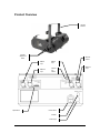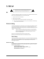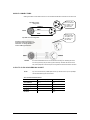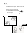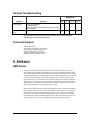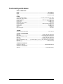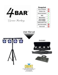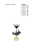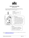
1
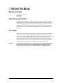
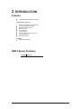
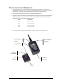
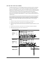
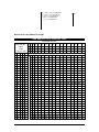
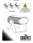
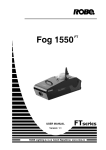
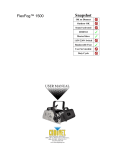
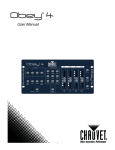
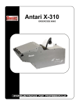
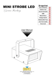
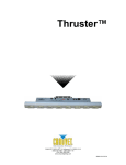
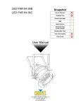
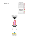
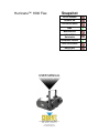
Hurricane™ 1800 Flex Snapshot OK on Dimmer Outdoor OK Sound Activated DMX Master/Slave 115 V / 230 V Switchable Resettable breaker User Serviceable Duty Cycle USER MANUAL 3000 N 29th Ct, Hollywood, FL 33020 U.S.A. (800) 762-1084 – (954) 929-1115 FAX (954) 929-5560 www.chauvetlighting.com TABLE OF CONTENTS 1. BEFORE YOU BEGIN ................................................................................................................................................... 3 WHAT IS INCLUDED .......................................................................................................................................................... 3 UNPACKING INSTRUCTIONS .............................................................................................................................................. 3 AC POWER ..................................................................................................................................................................... 3 SAFETY INSTRUCTIONS .................................................................................................................................................... 4 2. INTRODUCTION ........................................................................................................................................................... 5 FEATURES ...................................................................................................................................................................... 5 DMX CHANNEL SUMMARY ............................................................................................................................................... 5 PRODUCT OVERVIEW ...................................................................................................................................................... 6 3. SETUP .......................................................................................................................................................................... 7 BREAKER RESET ............................................................................................................................................................. 7 FIXTURE LINKING............................................................................................................................................................. 7 Data Cabling ............................................................................................................................................................. 7 DMX Data Cable ................................................................................................................................................ 7 Cable Connectors .............................................................................................................................................. 8 3-Pin to 5-Pin Conversion Chart ......................................................................................................................... 8 SETTING UP A DMX SERIAL DATA LINK ............................................................................................................................. 9 MASTER/SLAVE FIXTURE LINKING ..................................................................................................................................... 9 MOUNTING .................................................................................................................................................................... 10 Orientation ....................................................................................................................................................... 10 Rigging ............................................................................................................................................................ 10 4. OPERATING INSTRUCTIONS .................................................................................................................................... 11 OPERATION .................................................................................................................................................................. 11 DMX Mode .............................................................................................................................................................. 11 DMX CHANNEL VALUES................................................................................................................................................. 11 Auto cut-off feature ................................................................................................................................................. 11 Wireless Controller (FC-W) (Optional) ..................................................................................................................... 12 SETTING THE STARTING ADDRESS ............................................................................................................ 13 DMX Quick Reference Chart ............................................................................................................................ 14 GENERAL TROUBLESHOOTING ........................................................................................................................................ 16 TECHNICAL SUPPORT .................................................................................................................................................... 16 5. APPENDIX .................................................................................................................................................................. 16 DMX PRIMER................................................................................................................................................................ 16 WARNING! .................................................................................................................................................................. 17 RETURNS PROCEDURE .................................................................................................................................................. 18 CLAIMS ......................................................................................................................................................................... 18 CONTACT US ................................................................................................................................................................ 18 TECHNICAL SPECIFICATIONS .......................................................................................................................................... 19 Hurricane™ 1800 Flex User Manual 2 4/20/2010 4:33 PM 1. BEFORE YOU BEGIN What is included 1 x Hurricane™ 1800 Flex Warranty Card User Manual Unpacking Instructions Immediately upon receiving a fixture, carefully unpack the carton, check the contents to ensure that all parts are present, and have been received in good condition. Notify the shipper immediately and retain packing material for inspection if any parts appear damaged from shipping or the carton itself shows signs of mishandling. Save the carton and all packing materials. In the event that a fixture must be returned to the factory, it is important that the fixture be returned in the original factory box and packing. AC Power To determine the power requirements for a particular fixture, see the label affixed to the back plate of the fixture or refer to the fixture’s specifications chart. A fixture’s listed current rating is its average current draw under normal conditions. All fixtures must be powered directly off a switched circuit and cannot be run off a rheostat (variable resistor) or dimmer circuit, even if the rheostat or dimmer channel is used solely for a 0% to 100% switch. Before applying power to a fixture, check that the source voltage matches the fixture’s requirement. Check the fixture or device carefully to make sure that if a voltage selection switch exists that it is set to the correct line voltage you will use. Warning! Verify that the voltage rating on your unit matches the line voltage applied. Damage to your fixture may result if the line voltage applied does not match the voltage rating. All fixtures must be connected to circuits with a suitable Earth Ground. Hurricane™ 1800 Flex User Manual 3 4/20/2010 4:33 PM Safety Instructions Please read these instructions carefully, which includes important information about the installation, usage and maintenance of this product. Please keep this User Guide for future consultation. If you sell the unit to another user, be sure that they also receive this instruction booklet. Always make sure that you are connecting to the proper voltage, and that the line voltage you are connecting to is not higher than that stated on the decal or rear panel of the fixture. This product is intended for indoor use only! To prevent risk of fire or shock, do not expose fixture to rain or moisture. Make sure there are no flammable materials close to the unit while operating. The unit must be installed in a location with adequate ventilation, at least 20 in (50 cm) from adjacent surfaces. Be sure that no ventilation slots are blocked. Secure fixture to fastening device using a safety chain. Never carry the fixture solely by its head. Use its carrying handles. Maximum ambient temperature (Ta) is 104° F (40° C). Do not operate fixture at temperatures higher than this. In the event of a serious operating problem, stop using the unit immediately. Never try to repair the unit by yourself. Repairs carried out by unskilled people can lead to damage or malfunction. Please contact the nearest authorized technical assistance center. Never connect the device to a dimmer pack. Make sure the power cord is never crimped or damaged. Never disconnect the power cord by pulling or tugging on the cord. Caution! There are no user serviceable parts inside the unit. Do not open the housing or attempt any repairs yourself. In the unlikely event your unit may require service, please contact CHAUVET® at: 954-929-1115. Hurricane™ 1800 Flex User Manual 4 4/20/2010 4:33 PM 2. INTRODUCTION Features 1-channel DMX-512 flexible fog machine Additional Features Manually adjustable output angles (180º) 3-pin and 5-pin DMX connections Wired timer remote included Manual fog button 5L tank capacity 10 minute heat up Low fluid indicator and auto shut down LED-illuminated tank Water-based fogger OPTIONS Wireless remote (FC-W) DMX Channel Summary CHANNEL FUNCTION 1 Fog output Hurricane™ 1800 Flex User Manual 5 4/20/2010 4:33 PM Product Overview Hanging bracket Bracket adjustment knobs Remote control DMX in 5-pin DMX in 3-pin DMX out 3-pin Dipswitches DMX out 5-pin Manual fog button Power switch Breaker Power input Hurricane™ 1800 Flex User Manual 6 4/20/2010 4:33 PM 3. SETUP Disconnect the power cord before resetting the breaker. Note: the breaker will not reset until it has been allowed to cool. same type fuse. Breaker Reset This product is equipped with a breaker on the main power input, located on the exterior of the back panel. In the event that this breaker trips, you may reset it very easily. 1. Unplug the product from the mains power. 2. Allow to cool for 5-15 minutes. 3. Using your hand, press on the button for the breaker, until it remains in place. Note: In the event that this breaker will not reset, contact CHAUVET® for troubleshooting. The fixture may need to be serviced. Fixture Linking You will need a serial data link to run light shows of one or more fixtures using a DMX-512 controller or to run synchronized shows on two or more fixtures set to a master/slave operating mode. The combined number of channels required by all the fixtures on a serial data link determines the number of fixtures the data link can support. Important: Fixtures on a serial data link must be daisy chained in one single line. To comply with the EIA-485 standard no more than 32 devices should be connected on one data link. Connecting more than 32 fixtures on one serial data link without the use of a DMX optically-isolated splitter may result in deterioration of the digital DMX signal. Maximum recommended serial data link distance: 500 meters (1640 ft.) Maximum recommended number of fixtures on a serial data link: 32 fixtures Data Cabling To link fixtures together you must obtain data cables. You can purchase CHAUVET® certified DMX cables directly from a dealer/distributor or construct your own cable. If you choose to create your own cable please use data-grade cables that can carry a high quality signal and are less prone to electromagnetic interference. DM X D AT A C AB L E Use a Belden© 9841 or equivalent cable which meets the specifications for EIA RS-485 applications. Standard microphone cables cannot transmit DMX data reliably over long distances. The cable will have the following characteristics: 2-conductor twisted pair plus a shield Maximum capacitance between conductors – 30 pF/ft. Maximum capacitance between conductor and shield – 55 pF/ft. Maximum resistance of 20 ohms / 1000 ft. Nominal impedance 100 – 140 ohms Hurricane™ 1800 Flex User Manual 7 4/20/2010 4:33 PM C AB L E CO N N ECT O R S Cabling must have a male XLR connector on one end and a female XLR connector on the other end. 1 3 2 3-pin DMX connector configuration COMMON INPUT 1 3 2 1 3 2 DMX + DMX - Resistance 120 ohm 1/4w between pin 2 (DMX -) and pin 3 (DMX +) of the last fixture. OUTPUT Resistance 120 ohm 1/4w between pin 2 (DMX -) and pin 3 (DMX +) of the last fixture. 5-pin DMX connector configuration Termination reduces signal errors. To avoid signal transmission problems and interference, it is always advisable to connect a DMX signal terminator. CAUTION Do not allow contact between the common and the fixture’s chassis ground. Grounding the common can cause a ground loop, and your fixture may perform erratically. Test cables with an ohm meter to verify correct polarity and to make sure the pins are not grounded or shorted to the shield or each other. 3- PI N T O 5 - PI N CO N V ER S IO N CH ART Note! If you use a controller with a 5 pin DMX output connector, you will need to use a 5 pin to 3 pin adapter. The chart below details a proper cable conversion: 3 PIN TO 5 PIN CONVERSION CHART Conductor 3 Pin Female (output) 5 Pin Male (Input) Ground/Shield Pin 1 Pin 1 Data ( - ) signal Pin 2 Pin 2 Data ( + ) signal Pin 3 Pin 3 Not Used Pin 4 Not Used Pin 5 Hurricane™ 1800 Flex User Manual 8 4/20/2010 4:33 PM Setting up a DMX Serial Data Link Universal DMX Controller 1. Connect the (male) 3 pin connector side of the DMX cable to the output (female) 3 pin connector of the controller. 2. Connect the end of the cable coming from the controller which will have a (female) 3 pin connector to the input connector of the next fixture consisting of a (male) 3 pin connector. This drawing provides a general illustration of the DMX Input/Output panel of a lighting fixture. 3. Then, proceed to connect from the output as stated above to the input of the following fixture and so on. Continue the link Master/Slave Fixture Linking 1. Connect the (male) 3 pin connector side of the DMX cable to the output (female) 3 pin connector of the first fixture. 2. Connect the end of the cable coming from the first fixture which will have a (female) 3 pin connector to the input connector of the next fixture consisting of a (male) 3 pin connector. Then, proceed to connect from the output as stated above to the input of the following fixture and so on. Often, the setup for Master-Slave and Standalone operation requires that the first fixture in the chain be initialized for this purpose via DIP switches. Secondarily, the fixtures that follow may also require a slave setting. Please consult the “Operating Instructions” section in this manual for complete instructions for this type of setup and configuration. Slave 3000 N 29th Ct, Hollywood, FL 33020 U.S.A. (800) 762-1084 – (954) 929-1115 FAX (954) 929-5560 www.chauvetlighting.com Slave Master Mounting O RI E NT AT IO N This fixture may be mounted in a 90° degree angle (horizontal), provided there is adequate room for ventilation. The tank of the fixture should not move from this position. However, the front portion of the fog machine can tilt up and down in the desired direction. This is secured by using the bracket adjustment knobs. RIG G ING It is important never to obstruct the fan or vents pathway. Mount the fixture using, a suitable “C” or “O” type clamp. Adjust the angle of the fixture by loosening both knobs and tilting the fixture. After finding the desired position, retighten both knobs. When selecting installation location, take into consideration fluid tank access and routine maintenance. Safety cables must always be used. Never mount in places where the fixture will be exposed to rain, high humidity, extreme temperature changes, or restricted ventilation. Hanging Clamp Note! Clamp is sold separately. Pointing up Pointing down Hurricane™ 1800 Flex User Manual 10 4/20/2010 4:33 PM 4. OPERATING INSTRUCTIONS Operation DMX Mode This mode allows the unit to be controlled by any universal DMX controller. If you are unfamiliar with DMX, please read the DMX Primer in the Appendix of this manual. 1) This fixture will automatically switch to DMX mode operation, once a DMX controller has been plugged into the 3-pin or 5-pin DMX input. 2) Use DIP switches 1~9 to set the DMX address. DMX Channel Values CHANNEL VALUE 1 000 005 006 255 FUNCTION Fog output No function Fog output 0%~100% Auto cut-off feature This product has an auto cut-off safety feature to keep the machine from becoming damaged. This is referring to the operation of the pump. When the fluid tank is empty, the pump will still operate for a short period of time, until all of the fluid has been removed from the system. Then, it will sense that there is no fluid, and will automatically stop the fog output. An indication that this has occurred is when the blue LED’s that are lighting the fluid tank are flashing. Note: it will take approximately 30 seconds to 1 minute for this feature to engage once the fluid has emptied form the tank. Note: In order the fog machine to automatically reset, the trigger must be released. This may be from the wired remote, wireless remote, the manual fog button on the unit, or via a DMX controller. If it is via a DMX controller, then the DMX channel will have to be brought to a value of 000 (0%) in order to allow the fog machine to reset itself. Note: once the tank has been refilled with fog fluid, you may resume using the fog machine. The auto cut-off will automatically reset. Hurricane™ 1800 Flex User Manual 11 4/20/2010 4:33 PM Wireless Controller (FC-W) (Optional) This mode will allow you to control the fogger using the optional wireless controller. This consists of the transmitter and the receiver. You may control up to 4 independent fog machines or many more if you run them simultaneously. See the below instructions on setting up your fogger to operate with the FC-W. 1. Plug the wires receiver into the fog machine 5-pin port labeled “Remote Control”. 2. There are 4 buttons on the wireless remote transmitter which act as triggers. Each button can be assigned to a different fog machine. You may only choose 1 dipswitch on each receiver. See the below configuration for setting the receivers to operate with the transmitter remote. 3. Mode CH1 DIP Switches 1 = On, 2-4 = Off CH2 2 = On, 1,3,4 = Off CH3 3 = On, 1,2,4 = Off CH4 4 = On, 1,2,3 = Off Press the fog button, and the fog machine will output fog for as long as you hold down the button. LED indicator (ready) LED indicator (heating) Dipswitches Wireless Transmitter Fog Triggers Hurricane™ 1800 Flex User Manual Wireless Receiver 12 4/20/2010 4:33 PM S ET T ING T H E ST ART ING AD D R E SS This DMX mode enables the use of a universal DMX controller device. Each fixture requires a "start address" from 1 to 512. A fixture requiring one or more channels for control begins to read the data on the channel indicated by the start address. For example, a fixture that uses 6 DMX channels and was addressed to start on DMX channel 100, would read data from channels: 100, 101, 102, 103, 104, and 105. Choose start addresses so that the channels used do not overlap, and note the start address selected for future reference. If this is your first time addressing a fixture using the DMX-512 control protocol, we suggest jumping to the Appendix Section and reading the heading “DMX Primer”. It contains very useful information that will help you understand its use. Set the start address using the group of DIP switches located usually on bottom of the fixture. Each dip switch has an associated value. Adding the value of each switch in the ON position will provide the start address. Figuring out which switches to toggle ON given a specific start address can be accomplished by determining which switch values will add up to the address value, and turning these switches on. Do so by doing the following: 1) Determine the largest value switch that is less than the start address. Turn this switch on. 2) Subtract the value of the switch you just turned on from the starting address number. 3) Determine the largest value switch that is less than the remainder from the previous subtraction. Turn this switch on. 4) Subtract the value of the switch you just turned on from the remainder of the previous subtraction. 5) Repeat steps three and four until you have a remainder of zero. EXAMPLE STARTING ADDRESS 1 2 4 8 16 32 3 2 1 ON OFF 1 2 4 6 5 4 8 32 7 16 64 9 8 3 2 1 ON OFF Resolving address using simple math. DIP (DMX VALUE) SWITCH 1 2 3 4 5 6 7 8 Address 233 Hurricane™ 1800 Flex User Manual 6 5 4 128 Switch # 5 = 16 Switch # 4 = 8 Total = 24 9 8 7 256 Address 24 64 =8 =2 = 10 128 Switch # 4 Switch # 2 Total 256 Address 10 13 1 2 4 8 16 32 64 128 4/20/2010 4:33 PM 233 – (128) = 105, Turn ON Dip # 8 105 – (64) = 41, Turn ON Dip # 7 41 – (32) = 9, Turn ON Dip # 6 9 – (8) = 1, Turn ON Dip # 4 1 – (1) = 0, Turn ON Dip # 1 9 256 DM X Q U IC K R EF E RE NC E CH ART DMX Address Quick Reference Chart DIP Switch Position DMX DIP SWITCH SET 0=OFF 1=ON X=OFF or ON #1 #2 #3 #4 #5 0 0 0 0 0 1 0 0 0 0 0 1 0 0 0 1 1 0 0 0 0 0 1 0 0 1 0 1 0 0 0 1 1 0 0 1 1 1 0 0 0 0 0 1 0 1 0 0 1 0 0 1 0 1 0 1 1 0 1 0 0 0 1 1 0 1 0 1 1 0 0 1 1 1 0 1 1 1 1 0 0 0 0 0 1 1 0 0 0 1 0 1 0 0 1 1 1 0 0 1 0 0 1 0 1 1 0 1 0 1 0 1 1 0 1 1 1 1 0 1 0 0 0 1 1 1 0 0 1 1 0 1 0 1 1 1 1 0 1 1 0 0 1 1 1 #9 0 0 0 0 0 0 0 0 1 1 1 1 1 1 1 1 #8 0 #7 0 #6 0 0 0 1 0 1 0 0 1 1 1 0 0 1 0 1 1 1 0 1 1 1 0 0 0 0 0 1 0 1 0 0 1 1 1 0 0 1 0 1 1 1 0 1 1 1 1 2 3 4 5 6 7 8 9 10 11 12 13 14 15 16 17 18 19 20 21 22 23 24 25 26 27 28 32 33 34 35 36 37 38 39 40 41 42 43 44 45 46 47 48 49 50 51 52 53 54 55 56 57 58 59 60 64 65 66 67 68 69 70 71 72 73 74 75 76 77 78 79 80 81 82 83 84 85 86 87 88 89 90 91 92 96 97 98 99 100 101 102 103 104 105 106 107 108 109 110 111 112 113 114 115 116 117 118 119 120 121 122 123 124 128 129 130 131 132 133 134 135 136 137 138 139 140 141 142 143 144 145 146 147 148 149 150 151 152 153 154 155 156 160 161 162 163 164 165 166 167 168 169 170 171 172 173 174 175 176 177 178 179 180 181 182 183 184 185 186 187 188 192 193 194 195 196 197 198 199 200 201 202 203 204 205 206 207 208 209 210 211 212 213 214 215 216 217 218 219 220 224 225 226 227 228 229 230 231 232 233 234 235 236 237 238 239 240 241 242 243 244 245 246 247 248 249 250 251 252 256 257 258 259 260 261 262 263 264 265 266 267 268 269 270 271 272 273 274 275 276 277 278 279 280 281 282 283 284 288 289 290 291 292 293 294 295 296 297 298 299 300 301 302 303 304 305 306 307 308 309 310 311 312 313 314 315 316 320 321 322 323 324 325 326 327 328 329 330 331 332 333 334 335 336 337 338 339 340 341 342 343 344 345 346 347 348 352 353 354 355 356 357 358 359 360 361 362 363 364 365 366 367 368 369 370 371 372 373 374 375 376 377 378 379 380 384 385 386 387 388 389 390 391 392 393 394 395 396 397 398 399 400 401 402 403 404 405 406 407 408 409 410 411 412 416 417 418 419 420 421 422 423 424 425 426 427 428 429 430 431 432 433 434 435 436 437 438 439 440 441 442 443 444 448 449 450 451 452 453 454 455 456 457 458 459 460 461 462 463 464 465 466 467 468 469 470 471 472 473 474 475 476 480 481 482 483 484 485 486 487 488 489 490 491 492 493 494 495 496 497 498 499 500 501 502 503 504 505 506 507 508 Hurricane™ 1800 Flex User Manual 14 4/20/2010 4:33 PM 1 0 1 1 1 29 61 93 125 157 189 221 253 285 317 349 381 413 445 477 509 0 1 1 1 1 30 62 94 126 158 190 222 254 286 318 350 382 414 446 478 510 1 1 1 1 1 31 63 95 127 159 191 223 255 287 319 351 383 415 447 479 511 DIP Switch Position DMX Address Hurricane™ 1800 Flex User Manual 15 4/20/2010 4:33 PM General Troubleshooting Applies to Lights Foggers & Snow Controllers Dimmers & Chaser Use only DMX cables Install terminator Note: Keep DMX cables separated from power cables or black lights. Make sure connector is firmly connected to device Symptom Solution(s) Loss of signal Remote does not work If you still have a problem after trying the above solutions, please contact CHAUVET® Technical Support at the location listed below. Technical Support Address: Service Dept. 3000 N 29th Ct, Hollywood, FL 33020 (U.S.A.) Support (Email): [email protected] Telephone: (954) 929-1115 - (Press 4) Fax: (954) 929-5560 - (Attention: Service) Website: http://www.chauvetlighting.com 5. APPENDIX DMX Primer There are 512 channels in a DMX-512 connection. Channels may be assigned in any manner. A fixture capable of receiving DMX 512 will require one or a number of sequential channels. The user must assign a starting address on the fixture that indicates the first channel reserved in the controller. There are many different types of DMX controllable fixtures and they all may vary in the total number of channels required. Choosing a start address should be planned in advance. Channels should never overlap. If they do, this will result in erratic operation of the fixtures whose starting address is set incorrectly. You can however, control multiple fixtures of the same type using the same starting address as long as the intended result is that of unison movement or operation. In other words, the fixtures will be slaved together and all respond exactly the same. DMX fixtures are designed to receive data through a serial Daisy Chain. A Daisy Chain connection is where the DATA OUT of one fixture connects to the DATA IN of the next fixture. The order in which the fixtures are connected is not important and has no effect on how a controller communicates to each fixture. Use an order that provides for the easiest and most direct cabling. Connect fixtures using shielded two conductor twisted pair cable with three pin XLR male to female connectors. The shield connection is pin 1, while pin 2 is Data Negative (S-) and pin 3 is Data positive (S+). Hurricane™ 1800 Flex User Manual 16 4/20/2010 4:33 PM WARNING! Note: All fog machines are prone to clogging due to the thick consistency of fog liquid and the high temperature at which it vaporizes. However, a properly maintained fog machine should provide years of reliable use. Cleaning your fog machine regularly will help reduce costly replacement and repair charges. Maintenance Do not allow the fog machine to become contaminated. After every 40 hours of continuous operation, it is recommended to run a cleaning solution composed of 80% distilled water and 20% distilled vinegar through the system to prevent the accumulation of particulate matter in the heating element. The recommended cleaning regimen is as follows: 1. Empty all fog liquid from the machine. Add cleaning solution to tank. Plug unit in and begin warm up. 2. Run the unit in a well-ventilated area until the tank is almost empty. Do not allow the pump to run dry. 3. Replace nozzle. 4. Cleaning is now complete. Refill with fog liquid. Run the machine briefly to clear any cleaning solution from the pump and heater. 5. Do not operate the machine without liquid at any time. Storage 1. When storing run distilled water (not tap water) through the system as described in the cleaning regiment above. This will help avoid any particles condensing inside the pump or heater. 2. It is strongly recommended to test-run the machine on a monthly basis in order to achieve its best fogging condition. Caution: 1. Never place the fog/hazer machine on any flammable material (i.e. carpet, fabric etc.) during operation. All fog/hazer machines should always be on a non-flammable surface, such as concrete or tile. 2. Depending on the amount of fog/haze generated, all fog machines may set off smoke detectors. Hurricane™ 1800 Flex User Manual 17 4/20/2010 4:33 PM Returns Procedure Returned merchandise must be sent prepaid and in the original packing, call tags will not be issued. Package must be clearly labeled with a Return Merchandise Authorization Number (RMA #). Products returned without an RMA # will be refused. Call CHAUVET® and request RMA # prior to shipping the fixture. Be prepared to provide the model number, serial number and a brief description of the cause for the return. Be sure to properly pack fixture, any shipping damage resulting from inadequate packaging is the customer’s responsibility. CHAUVET® reserves the right to use its own discretion to repair or replace product(s). As a suggestion, proper UPS packing or double-boxing is always a safe method to use. Note: If you are given an RMA #, please include the following information on a piece of paper inside the box: 1) Your name 2) Your address 3) Your phone number 4) The RMA # 5) A brief description of the symptoms Claims Damage incurred in shipping is the responsibility of the shipper; therefore the damage must be reported to the carrier upon receipt of merchandise. It is the customer's responsibility to notify and submit claims with the shipper in the event that a fixture is damaged due to shipping. Any other claim for items such as missing component/part, damage not related to shipping, and concealed damage, must be made within seven (7) days of receiving merchandise. Contact Us World Wide General Information CHAUVET® 3000 North 29th Court Hollywood, FL 33020 voice: 954.929.1115 fax: 954.929.5560 toll free: 800.762.1084 Technical Support CHAUVET® 3000 North 29th Court Hollywood, FL 33020 voice: 954.929.1115 (Press 4) fax: 954.929.5560 (Attention: Service) World Wide Web www.chauvetlighting.com Hurricane™ 1800 Flex User Manual 18 4/20/2010 4:33 PM Technical Specifications WEIGHT & DIMENSIONS Length ........................................................................................................................... 26 in (585 mm) Width.......................................................................................................................... 13.6 in (347 mm) Height ........................................................................................................................ 14.7 in (374 mm) Weight....................................................................................................................... 27.6 lbs (12.5 kg) POWER AC power (voltage specific) ........................................................... 115 VAC, 60 Hz or 230 VAC, 50Hz Breaker size (120 V version) .............................................................................................. 15 A, 125 V Power Consumption ............................................................................. 1,364 W (11.9 A) max @ 120 V Inrush current ............................................................................................................ (11.7 A) @ 120 V Power Factor................................................................................................................... 0.99 @ 120 V Breaker size (230 V version) ................................................................................................ 8 A, 250 V Power Consumption ............................................................................. 1,350 W (5.86 A) max @ 230 V Inrush current ................................................................................................................. (6 A) @ 230 V Power Factor................................................................................................................... 0.99 @ 230 V Output ................................................................................................................................. 25,000 cfm Fluid consumption ............................................................................................................... 125 ml/min THERMAL Maximum ambient temperature ...................................................................................... 104° F (40° C) CONTROL & PROGRAMMING Data input ............................................................................................. locking 3-pin XLR male socket Data output ........................................................................................ locking 3-pin XLR female socket Data pin configuration (3-pin) ................................................................. pin 1 shield, pin 2 (-), pin 3 (+) Data input ............................................................................................. locking 5-pin XLR male socket Data output ........................................................................................ locking 5-pin XLR female socket Data pin configuration (5-pin) ............ pin 1 shield, pin 2 (-), pin 3 (+), pin 4 (not used), pin 5 (not used) Protocols .....................................................................................................................DMX-512 USITT DMX Channels ....................................................................................................................................1 ORDERING INFORMATION Hurricane™ 1800 Flex .................................................................................... HURRICANE1800FLEX WARRANTY INFORMATION Warranty ........................................................................................................... 1-year limited warranty Hurricane™ 1800 Flex User Manual 19 4/20/2010 4:33 PM