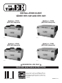
1
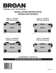
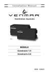
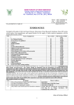
®
INSTALLATION GUIDE
VÄNEE HRV 60H AND ERV 60H
Model no.: 41602
(HRV with top ports)
VB0072
Model no.: 41600
(HRV with side ports)
VB0076
Model no.: 41606
(ERV with top ports)
VB0073
Model no.: 41604
(ERV with side ports)
VB0075
! RESIDENTIAL USE ONLY !
READ AND SAVE THESE INSTRUCTIONS
These products earned the ENERGY STAR® by
meeting strict energy efficiency guidelines set by
Natural Resources Canada and the US EPA. They
meet ENERGY STAR requirements only when used
in Canada.
06010B rev. 15
ABOUT THIS MANUAL
Because of the large amount of models covered by this publication, the illustrations are typical ones. Some details of your unit may be
slightly different than the ones shown.
Please take note that this manual uses the following symbols to emphasize particular information:
! WARNING
Identifies an instruction which, if not followed, might cause serious personal injuries including possibility of death.
CAUTION
Identifies an instruction which, if not followed, may severely damage the unit and/or its components.
NOTE: Indicates supplementary information needed to fully complete an instruction.
We welcome any suggestions you may have concerning this manual and/or the unit, and we would appreciate hearing your comments on
ways to better serve you. Please contact us by phone at 1-800-567-3855.
ABOUT THESE UNITS
LIMITATION
For residential (domestic) installation only. Installation work and electrical wiring must be done by a qualified person(s) in accordance with
all applicable codes and standards, including fire-rated construction codes and standards.
i WARNING
TO REDUCE THE RISK OF FIRE, ELECTRIC SHOCK, OR INJURY TO PERSON(S) OBSERVE THE FOLLOWING:
1. Use this unit only in the manner intended by the manufacturer. If you have questions, contact the manufacturer at the address or
telephone number listed in the warranty.
2. Before servicing or cleaning the unit, disconnect power cord from electrical outlet.
3. This unit is not designed to provide combustion and/or dilution air for fuel-burning appliances.
4. When cutting or drilling into wall or ceiling, do not damage electrical wiring and other hidden utilities.
5. Do not use this unit with any solid-state speed control device other than following main wall controls: Platinum, Deco-Touch, Lite-Touch
Bronze, Simple-Touch Bronze or Bronze, and no other optional wall controls than 60-minute crank timer and/or 20-minute lighted push
button and/or Dehumidistat.
6. This unit must be grounded. The power supply cord has a 3-prong grounding plug for your personal safety. It must be plugged into a
mating 3-prong grounding receptacle, grounded in accordance with the national electrical code and local codes and ordinances. Do
not remove the ground prong. Do not use an extension cord.
7. Do not install in a cooking area or connect directly to any appliances.
8. Do not use to exhaust hazardous or explosive materials and vapors.
9. When performing installation, servicing or cleaning these units, it is recommended to wear safety glasses and gloves.
10. Due to the weight of the unit, two installers are recommended to perform installation.
11. When applicable local regulation comprise more restrictive installation and/or certification requirements, the aforementioned
requirements prevail on those of this document and the installer agrees to conform to these at his own expenses.
CAUTION
1.
2.
3.
4.
5.
6.
7.
8.
To avoid prematurate clogged filters, turn OFF the unit during construction or renovation.
Please read specification label on product for further information and requirements.
Be sure to duct air outside – Do not intake/exhaust air into spaces within walls or ceiling or into attics, crawl spaces, or garage.
Intended for residential installation only in accordance with the requirements of NFPA 90B (for a unit installed in U.S.A.) or Part 9 of the
National Building Code of Canada (for a unit installed in Canada).
Do not run any air ducts directly above or closer than 2 ft (0.61 m) to any furnace or its supply plenum, boiler, or other heat producing
appliance. If a duct has to be connected to the furnace return plenum, it must be connected not closer than 9’ 10” (3 m) from this plenum
connection to the furnace.
The ductwork is intended to be installed in compliance with all local and national codes that are applicable.
When leaving the house for a long period of time (more than two weeks), a responsible person should regularly check if the unit
operates adequately.
If the ductwork passes through an unconditioned space (e.g.: attic), the unit must operate continuously except when performing
maintenance and/or repair. Also, the ambient temperature of the house should never drop below 18°C (65°F).
2
TABLE OF CONTENTS
1. TYPICAL INSTALLATIONS ......................................................................................................................... 4-5
1.1
FULLY DUCTED SYSTEM ..........................................................................................................................................4
1.2
CENTRAL DRAW POINT ...........................................................................................................................................4
1.3
SIMPLIFIED INSTALLATION .........................................................................................................................................4
1.4
ATTIC INSTALLATION FOR ERV UNITS ONLY ...............................................................................................................5
2. INSTALLATION ..................................................................................................................................... 5-10
2.1
INSPECT THE CONTENT OF THE BOX........................................................................................................................ .5
2.2
LOCATING THE UNIT ...............................................................................................................................................5
2.3
UNIT PREPARATION ............................................................................................................................................ 5-6
2.4
HOW TO HANG THE UNIT ........................................................................................................................................6
2.5
PLANNING OF THE DUCTWORK..................................................................................................................................7
2.6
INSTALLING THE DUCTWORK AND REGISTERS ..........................................................................................................7-8
2.7
CONNECTING THE DUCTS TO THE UNIT ......................................................................................................................9
2.8
INSTALLING THE TANDEM® TRANSITION KIT..................................................................................................................9
2.9
INSTALLING 2 EXTERIOR HOODS .............................................................................................................................10
3. CONTROLS.......................................................................................................................................10-12
3.1
INTEGRATED CONTROL ..........................................................................................................................................10
3.2
ELECTRICAL CONNECTION TO OPTIONAL WALL CONTROLS ..................................................................................... 11-12
3.2.1 ELECTRICAL CONNECTION TO PLATINUM MAIN WALL CONTROL ................................................................................... 11
3.2.2 ELECTRICAL CONNECTION TO DECO-TOUCH MAIN WALL CONTROL .............................................................................. 11
3.2.3 ELECTRICAL CONNECTION TO LITE-TOUCH BRONZE OR SIMPLE-TOUCH BRONZE MAIN WALL CONTROLS ........................... 11
3.2.4 ELECTRICAL CONNECTION TO BRONZE MAIN WALL CONTROL ..................................................................................... 11
3.2.5 ELECTRICAL CONNECTION TO OPTIONAL AUXILIARY WALL CONTROLS ...........................................................................12
4. ELECTRICAL CONNECTION TO THE FURNACE ................................................................................................12
5. WIRING DIAGRAM ..................................................................................................................................13
6. BALANCING THE UNIT ..............................................................................................................................14
7. CONNECTING THE DRAIN (HRV UNITS ONLY).............................................................................................15
8. SERVICE PARTS.....................................................................................................................................16
9. TROUBLESHOOTING ........................................................................................................................... 17-18
3
1.
TYPICAL INSTALLATIONS
Installations may vary according to the type of unit and the ports configuration (top or sides). Use the following illustrations as guidelines
to help you decide on how the unit will be installed.
All the units should be hung from the joists.
In every case, bathroom fans and a range hood should be used to exhaust stale air. Also, for homes with more than one level, we
recommend one exhaust register at the highest level.
There are 3 installation methods: Fully ducted, Central Draw Point and Simplified Installation.
NOTE: An electrical outlet has to be available within 3 feet of the unit.
1.1
FULLY DUCTED SYSTEM (PRIMARILY FOR HOMES WITH RADIANT HOT WATER OR ELECTRIC BASEBOARD HEATING)
Stale air coming from the registers located at the highest level of the house
is exhausted to the outside. Fresh air from outside is filtered and supplied by
the register located in the lowest liveable level.
Homes with more than one level require at least one exhaust register at the
highest level.
See figure at right.
VH0055
1.2
CENTRAL DRAW POINT (CONNECTION TO A FORCED AIR SYSTEM)
Stale air coming from the registers located at the highest level of the house
is exhausted to the outside. Fresh air from outside is filtered and supplied
to the return (plenum) or the supply duct of the forced air unit. See figure
at right.
For this type of installation, it is not essential that the forced air system
blower runs when the unit is in operation, but we recommend it.
NOTE: Home with multiple forced air systems should have one unit on each
system.
VH0056
1.3
SIMPLIFIED INSTALLATION (CONNECTION TO A FORCED AIR SYSTEM)
Stale air is exhausted to the outside. Fresh air from outside is filtered and
supplied to the return (plenum) or the supply duct of the forced air unit.
See figure at right.
To avoid cross-contamination and achieve the highest efficiencies, the
forced air system blower must always be ON.
NOTE: Home with multiple forced air systems should have one unit on each
system.
VH0057
4
1.
TYPICAL INSTALLATIONS (CONT’D)
1.4
ATTIC INSTALLATION FOR ERV UNITS ONLY
All 3 types of installations can be used in the attic (Fully ducted system, Central Draw Point or Simplified). The example shown below is a
Simplified installation (connection to a forced air system).
NOTE: To get the most of your ERV unit, the ambient temperature around the unit should be conditioned. If the unit has to be installed in
an unconditioned space, the heat gains or losses from the unit and the ducts could increase the operation costs of the unit.
CAUTION
• Due to the potential temperature difference between the attic and the rest of the house, all unit ducts must be insulated.
• The attic temperature must always be above 0°C (32°F) and under 65°C (149°F).
Stale air is exhausted to the outside. Fresh air from outside is filtered
and supplied to the return (plenum) of the forced air unit. See figure
at right.
To avoid cross-contamination and achieve the highest efficiencies, the
forced air system blower must always be ON.
NOTE: Home with multiple forced air systems should have 1 unit on
each system.
2.
2.1
VH0058
INSTALLATION
INSPECT THE CONTENTS OF THE BOX
• Inspect the exterior of the unit for shipping damage. Ensure that there is no damage to the door, door latches, power cord, etc.
• Remove and discard both transport brackets (A) and open the door. Discard the styrofoam
fillers (ERV units only) and remove the hardware kit from the unit. Inspect the interior of the
unit for damage. Ensure that heat or energy recovery core, core filters, insulation, dampers,
etc. are all intact.
A
VD0183
2.2
LOCATING THE UNIT
Choose an appropriate location for the unit.
• Within an area of the house where the ambient temperature is kept between 18°C (65°F) and 40°C (104°F).
• So as to provide easy access to the interior of the unit, for semi-annual and annual maintenance.
• Close to an exterior wall, so as to limit the length of the insulated flexible duct to and from the unit.
• Away from hot chimneys and other fire hazards.
• Allow for a power source (standard 3-prong grounding outlet).
• For HRV units ONLY: Close to a drain. If no drain is close by, use a pail to collect run-off.
2.3
UNIT PREPARATION
Both HRV and ERV units are equipped with 2 ports having integrated balancing damper. Turn the thumb B
screw (B) clockwise to manually open and adjust the damper (C).
HRV UNITS: Set the Fresh air to building port to wide open position, and adjust the Exhaust air to outside port
to 3rd notch.
C
NOTE: If the unit needs to be balanced, adjust the damper of the Exhaust air to outside port to wide open
position. See Section 6.
ERV UNITS: Set both Fresh air to building port and Exhaust air to outside port to wide open position.
VJ0032
Port with integrated balancing
damper - Top view
5
2.
INSTALLATION (CONT’D)
2.3
UNIT PREPARATION (CONT’D)
The door latches location can be changed from sides to front of the unit, according to the installation needs.
VD0176
Latches on sides of the unit
Latches in front of the unit
To do so, turn the unit upside down. Open the latches an unscrew them from the unit. Install the latches on their new locations.
VB0094
VO0090
VO0089
2.4
HOW TO HANG THE UNIT
Hang the unit with the 4 chains, hooks and springs
provided.
CAUTION
Make sure the unit is level.
VD0185
VD0184
If there is not enough space on top of the unit, slightly bend the hooks and install them
lower on the unit. See figure at right.
VD0187
6
2.
INSTALLATION (CONT’D)
2.5
PLANNING OF THE DUCTWORK
• Keep it simple. Plan for a minimum of bends and joints.
• Keep the length of insulated ducts to a minimum.
• Do not ventilate crawl spaces or cold rooms. Do not attempt to recover the exhaust air from a dryer or a range hood. This would
cause clogging of the filters and recovery module.
• If the house has two floors or more, be sure to plan for at least one exhaust register on the highest lived-in level.
2.6
INSTALLING THE DUCTWORK AND REGISTERS
! WARNING
Never install a stale air exhaust register in a closed room where a combustion device operates, such as a gas furnace, a gas
water heater or a fireplace.
2.6.1 FULLY DUCTED SYSTEM (AS ILLUSTRATED IN SECTION 1.1)
Stale air exhaust ductwork:
• Install the stale air exhaust registers where the contaminants are produced: Kitchen, living room, etc. Position the registers as far
from the stairway as possible and in such a way that the air circulates in all the lived-in spaces in the house.
• If a register is installed in the kitchen, it must be located at least 4 feet (1.2 m) from the range.
• Install the registers 6 to 12 inches (152 to 305 mm) from the ceiling on an interior wall OR install them in the ceiling.
Fresh air distribution ductwork:
• Install the fresh air distribution registers in bedrooms, dining rooms, living room and basement.
• Keep in mind that the fresh air registers must be located as far as possible from the stale air registers.
• Install the registers in the ceiling OR 6 to 12 inches (152 to 305 mm) from the ceiling on an interior wall. The duct length should be
at least 15’ (4.6 m). (The fresh air will then flow through the room and mix with room air, ensuring a continuous renewed airflow.)
• If a register must be floor installed, direct the airflow up the wall.
2.6.2 CENTRAL DRAW POINT SYSTEM (AS ILLUSTRATED IN SECTION 1.2)
Stale air exhaust ductwork:
Same as for Fully Ducted System, described on point 2.6.1
Fresh air distribution ductwork:
! WARNING
When performing duct connections, always use approved tools and materials. Respect all corresponding laws and safety
regulations. Please refer to your local building code.
CAUTION
When performing duct connections to the furnace supply duct, this duct must be sized to support the additional airflow
produced by the HRV/ERV. Also, use a steel duct.
There are 2 methods for connecting the unit to the furnace/air handler:
Method 1: Supply side connection
• Cut an opening into the furnace supply duct at least 18 inches (0.5 m) from the
furnace/air handler.
• Connect this opening to the Fresh air to building port of the HRV/ERV (use steel
duct, see figure at right).
MINIMUM 18"
(0.5 M)
STEEL DUCT
• Make sure the HRV/ERV duct forms an elbow inside the furnace/air handler ductwork.
• If desired, interlock (synchronize) the furnace/air handler blower operation (see
Section 4).
VJ0036
Method 2: Return side connection
A
• Cut an opening into the furnace return duct not less than 10 feet (3.1 m) from the
furnace/air handler (A+B).
• Connect this opening to the Fresh air to building port of the HRV/ERV(see figure at right).
NOTE: For Method 2, it is not essential that the furnace/air handler runs when the unit is in
operation, but we recommend it. If desired, interlock (synchronize) the furnace/air
handler blower operation (see Section 4).
7
B
VJ0035
A+B= NOT LESS
THAN 10' (3.1 M)
2.
2.6
INSTALLATION (CONT’D)
INSTALLING THE DUCTWORK AND REGISTERS (CONT’D)
2.6.3 SIMPLIFIED INSTALLATION (AS ILLUSTRATED IN SECTION 1.3)
! WARNING
When performing duct connections, always use approved tools and materials. Respect all corresponding laws and/or safety
regulations. Please refer to your local building code.
CAUTION
When performing duct connections to the furnace supply duct, this duct must be sized to support the additional airflow
produced by the HRV/ERV. Also, use a steel duct. For a Return-Return installation, the furnace blower must be in operation
when the HRV/ERV is in operation.
There are 2 methods for connecting the unit to the furnace/air handler:
Method 1: Supply-return connection
Method 2: Return-return
A+B= NOT LESS
10' (3.1 M)
THAN
MINIMUM 18"
(0.5 M)
MINIMUM 3'
(0.9 M)
A
B
STEEL DUCT
A
B
VJ0038
A+B= NOT LESS
10' (3.1 M)
THAN
VJ0037
Stale air intake:
• Cut an opening into the furnace/air handler return duct not less than 10 feet (3.1 m) from the furnace/air handler (A+B).
• Connect this opening to the Exhaust air from building port of the HRV/ERV.
Fresh air distribution:
• Same instructions as for Method 1 or Method 2, Section 2.6.2.
For Method 2 (Return-return), make sure there is a distance of at least 3 feet (0.9 m) between the 2 connections to the furnace/
air handler.
NOTE: For Method 1, it is not essential to synchronize the furnace blower operation with the unit operation, but we recommend it.
CAUTION
If using Method 2, make sure the furnace/air handler blower operation is synchronized with the unit operation! See Section 4.
8
2.
INSTALLATION (CONT’D)
2.7
CONNECTING THE DUCTS TO THE UNIT
Insulated flexible ducts:
Use the following procedure for connecting the insulated flexible ducts to the port of the unit (Exhaust air to outside and Fresh air
from outside ports).
CAUTION
Make sure the balancing dampers are set to their appropriate position before connecting the ducts to the ports. See Section 2.3.
VJ0042
VJ0041
VJ0043
VJ0039
VJ0040
Pull back the insulation to expose
the flexible duct.
Attach the flexible duct
to the port using tie
wrap.
Pull the insulation over
the joint and tuck in
between the inner
and outer rings of the
double collar.
Pull the vapor barrier
over the insulation and
over the outer ring of
the double collar.
CAUTION
Make sure the
vapor barrier on
the insulated ducts
does not tear during
installation to avoid
condensation
within the ducts.
Apply duct tape to
the joint making an
airtight seal. Avoid
compressing
the
insulation when pulling
the tape tightly around
the joint.
Compressed insulation
loses its R value and
causes water dripping
due to condensation
on the exterior surface
of the duct.
Rigid ducts:
CAUTION
Do not use screws to connect the rigid ducts to the ports.
Use a small length of flexible duct to connect the rigid duct to the ports in order to avoid vibration transmissions. Use tie-wraps to
perform connections.
2.8
INSTALLING THE TANDEM® TRANSITION* KIT
The joist opening needed to install the Tandem® transition must be 9¾” minimum. The
maximum height of the Tandem® transition is 8¾”.
To connect the insulated flexible ducts to the Tandem® transition (Exhaust air to
outside and Fresh air from outside), follow the instructions included with the Tandem®
transition kit (part no.14690).
*Patented.
VR0003
Tandem® transition kit
NOTE: If the joist are perpendicular to the ducts, or if the connection to the exterior hood is in a limited area, the installation will need
2 exterior hoods instead of one. See next Section 2.9 INSTALLING 2 EXTERIOR HOODS.
9
2.
INSTALLATION (CONT’D)
2.9
INSTALLING 2 EXTERIOR HOODS
6" Ø
(152 MM)
EXHAUST HOOD
OPTIONAL DUCT
LOCATION
INTAKE HOOD
18"
(457 MM)
Choose an appropriate location to install the exterior hoods:
•
There must be a minimum distance of 6’ (1.8 m)
between the hoods to avoid cross-contamination
•
There must be a minimum distance of 18” (457 mm)
from the ground
6'
(1.8 M)
18"
(457 MM)
6'
(1.8 M)
! WARNING
18"
(457 MM)
Make sure the intake hood is at least 6 feet (1.8 m)
away from any of the following:
• Dryer exhaust, high efficiency furnace vent, central
vacuum vent
• Gas meter exhaust, gas barbecue-grill
• Any exhaust from a combustion source
• Garbage bin and any other source of contamination
TAPE AND DUCT TIE
Refer to figure at right for connecting insulated ducts to
the exterior hoods. An “Anti-gust intake hood” should be
installed in regions where a lot of snow is expected to fall.
VD0028
3.
3.1
CONTROLS
INTEGRATED CONTROL
All units are equipped with an integrated control, located under the unit, in front of the
electrical compartment. Use the push button (1) to control the unit. The LED (2) will then
shows on which mode the unit is in. Refer to table below.
WARNING
AVERTISSEMENT
Risk of electric shock. Before performing
any maintenance or servicing, always
disconnect the unit from its power source.
Danger d’électrocution. Débranchez
toujours l’appareil avant d’entreprendre
des travaux d’entretien ou de réparation.
CAUTION
ATTENTION
Unscrew both screws to open the electrical Dévisser les deux vis pour ouvrir le compartiment
compartment. To completely remove, detach électrique. Pour retirer complètement, le
from its retention wire inside.
détacher de son fil de rétention intérieur.
LED COLOR
RESULTS
AMBER
UNIT IS ON LOW SPEED
GREEN
UNIT IS ON HIGH SPEED
NO LIGHT
UNIT IS OFF OR CONTROLLED BY A MAIN CONTROL
No light
OFF or remote controled
Amber light
LOW speed
Green ligh
HIGH speed
Blinking light
See User Manual
Sans lumière
Arrêté ou contrôlé
par contrôle mural
Lumière ambre
Basse vitesse
Lumière verte
Haute vitesse
Clignotant
Voir guide d’utilisation
VD0182
1 2
If a problem occurs during the unit operation, its integrated control LED (2) will blink. The color of the blinking light depends on the type of
error detected. Refer to Section 9 TROUBLESHOOTING on page 17 for further details.
3.1.1 BOOT SEQUENCE
The unit boot sequence is similar to a personal computer boot sequence. Each time the unit is plugged after being unplugged, or
after a power failure, the unit will perform a 30-second booting sequence before starting to operate. During the booting sequence,
the integrated control LED will light GREEN or AMBER for 5 seconds, and then will shut off for 2 seconds. After that, the LED will
light RED for the rest of the booting sequence. During this RED light phase, the unit is checking and resetting the motorized damper
position. Once the motorized damper position completely set, the RED light turns off and the booting sequence is done.
NOTE: No command will be taken until the unit is fully booted.
10
3.
CONTROLS (CONT’D)
3.2
ELECTRICAL CONNECTION TO OPTIONAL WALL CONTROLS
For more convenience, this unit can also be controlled using an optional main wall control.
NOTES: 1. The integrated control must be turned OFF to use an optional main control.
2. If an optional auxiliary control is used, if activated, the auxiliary control operation will override the optional main control.
! WARNING
Always disconnect the unit before making any connections. Failure in disconnecting power could result in electric shock or
damage of the wall control or electronic module inside the unit.
CAUTION
Never install more than one optional main wall control per unit. Make sure that the wires do not short-circuit between
themselves or by touching any other components on the wall control. Avoid poor wiring connections. To reduce electrical
interference (noise) potential, do not run wall control wiring next to control contactors or near light dimming circuits, electrical
motors, dwelling/building power or lighting wiring, or power distribution panel.
B
A
Use the terminal connector included in the installation kit to perform the electrical
connection for main and optional wall controls. Check if all wires are correctly inserted in
their corresponding holes in the terminal block. (A wire is correctly inserted when its orange
receptacle is lower than another one without wire. On picture at right, wire A is correctly
inserted, but not wire B.)
VE0272
3.2.1 ELECTRICAL CONNECTION TO PLATINUM
MAIN WALL CONTROL
3.2.2 ELECTRICAL CONNECTION TO DECO-TOUCH
MAIN WALL CONTROL
NO C NC I OC OL Y R G B
SET
SMART
VE0250
VE0174
3.2.4 ELECTRICAL CONNECTION TO BRONZE
MAIN WALL CONTROL
3.2.3 ELECTRICAL CONNECTION TO LITE-TOUCH
BRONZE OR SIMPLE-TOUCH BRONZE
MAIN WALL CONTROLS
RE HUMID
MO
ATIVE HUM IDI
TY
REL
20%
5°C
41°F
25%
CO
HUMIDITY
CONTROL
F
OF
NO C NC I OC OL Y R G B
%
MAIN WALL CONTROL
LITE-TOUCH BRONZE
and
SIMPLE TOUCH BRONZE
REAR VIEW
MF O R Z O N E
T
MODE
PREF
NO C NC I OC OL Y R G B
-5°C
2330%
°F
70%
CO
M FORT ZONE
40%
LE S
S H U MI D
60%
50%
-20°C
-4°F
-30°C
-22°F
NO C NC I OC OL Y R G B
Y
G B
Y
G B
VE0326A
NOTE: On some older wall control models, the left
terminal is identified OC instead of Y; connect
this terminal to Y on terminal connector.
VE0103
11
MAX.
OFF
MIN.
3.
CONTROLS (CONT’D)
3.2
ELECTRICAL CONNECTION TO OPTIONAL WALL CONTROLS (CONT’D)
3.2.5 ELECTRICAL CONNECTION TO OPTIONAL AUXILIARY WALL CONTROLS
60-MINUTE
CRANK TIMER
DEHUMIDISTAT
%
ATI VE HUM IDI
TY
REL
OFF
20%
DEHUMIDISTAT
NOTE: If an optional auxiliary wall control is
activated and then, the Dehumidistat is
being activated, this one will override
the auxiliary wall control commands.
25%
NO C NC I OC OL Y R G B
20-MINUTED LIGHTED PUSH BUTTON
(5 MAXIMUM)
70%
30%
CO
M FO R T Z O N E
60%
50%
40%
DURING FALL, WINTER
AND SPRING, SET THE
DIAL ACCORDING TO
THE DESIRED MAXIMUM
INDOOR HUMIDITY LEVEL.
DURING SUMMER SET
THE DIAL TO THE
OFF POSITION.
VE0105A
Once the wall control(s) connections have been made, insert the terminal connector in the bottom of the unit, on the electrical compartment
front face.
WARNING
AVERTISSEMENT
Risk of electric shock. Before performing
any maintenance or servicing, always
disconnect the unit from its power source.
Danger d’électrocution. Débranchez
toujours l’appareil avant d’entreprendre
des travaux d’entretien ou de réparation.
CAUTION
ATTENTION
Unscrew both screws to open the electrical Dévisser les deux vis pour ouvrir le compartiment
compartment. To completely remove, detach électrique. Pour retirer complètement, le
from its retention wire inside.
détacher de son fil de rétention intérieur.
No light
OFF or remote controled
Amber light
LOW speed
Green ligh
HIGH speed
Blinking light
See User Manual
Sans lumière
Arrêté ou contrôlé
par contrôle mural
Lumière ambre
Basse vitesse
Lumière verte
Haute vitesse
Clignotant
Voir guide d’utilisation
TERMINAL
CONNECTOR
VD0182
NOTE: For information about the operation of the wall controls, refer to the Main and auxiliary wall controls user guide.
4.
ELECTRICAL CONNECTION TO THE FURNACE
! WARNING
Never connect a 120-volt AC circuit to the terminals of the furnace interlock (standard wiring). Only use the low voltage class
2 circuit of the furnace blower control.
For a furnace connected to a cooling system:
On some older thermostats, energizing the “R” and “G” terminals at the furnace has the effect of energizing “Y” at the thermostat and
thereby turning on the cooling system. If you identify this type of thermostat, you must use the ALTERNATE FURNACE INTERLOCK WIRING.
ALTERNATE FURNACE INTERLOCK WIRING
STANDARD FURNACE INTERLOCK WIRING
THERMOSTAT
TERMINALS
FOUR
WIRES
TWO WIRES
heating only
W
R
G
W
4 WIRES
G
Y
THERMOSTAT
TERMINAL
2 WIRES
heating only
wiring
nuts
W
RR
NO
NC
G
C
C
C
YY
Y
FURNACE
24-VOLT
TERMINAL BLOCK
R
UNIT TERMINAL CONNECTOR
Y
NO C NC I OC OL Y R G B
G
UNIT TERMINAL CONNECTOR
R
NO C NC I OC OL Y R G B
W
FURNACE
24-VOLT
TERMINAL BLOCK
TWO WIRES
2 WIRES
COOLING SYSTEM
VE0108A
12
COOLING SYSTEM
13
G
BN
BN
BL
BL
J4
J6
J7
J5
J8
3 2 1
F1
W1
BK W
J10
4 321
See note 1 2 1
J9
MED HI
120 V, 60 Hz
2
1
1
2
3
1
2
3
2
1
5 4 3 2 1
R
BL
R
P
BK
BL
GR
BL
BL
R
BL
Low - Med (81)
Med (64) - High (106)
Low - High (106)
Ref 1 FAN SPEEDS (Voltage)
BK
BL
R
BL
BK
MED HI
JU1
3 2 1
Ref 1
J2
Low - High (120)
G
12
J11
J12
J3
12
54321
BK
J1
R1
BK
BL
BN
G
GR
O
P
R
W
Y
nc
BLACK
BLUE
BROWN
GREEN
GREY
ORANGE
PURPLE
RED
WHITE
YELLOW
no connection
COLOR CODE
Furnace blower interlock
J14-1 : NO
J14-2 : COM
J14-3 : nc
(optional; see notes 3, 5)
Override
switch
(optional; see
notes 3 & 4)
BKG R Y
Field wiring
remote control
(see notes 3 & 4)
t°
Defrost
temperature sensor
DAMPER
ELECTRONIC ASSEMBLY
10
9
8
J13 7
6
5
ICP
4
3
2
1
J14
21
A2
ELECTRONIC
ASSEMBLY A1
1 2 3 4 5
S1
BK
Door interlock switch
T1
(magnetically actuated
120
V
BK
reed switch)
24 V
O
BL 106 V
class 2
81 V
P
O
BN 71 V
GR 64 V
W
W
57 V
9.5 V
R
class 2
W
neutral
BL
BL
Y
R
BK
Y
nc
P
nc
BN
nc
GR
nc
R
Setting for test purpose only
Low-Med select
Med-High select
Factory shipped
SETTING
VE0324A
BK
R
R
R
R
BK
Ref
1
BK
BK
NOTES
1. Use specified UL listed/CSA Certified line fuse
(3A, 3AG Type).
2. If any of the original wire, as supplied, must
be replaced, use the same equivalent wire.
3. Field wiring must comply with applicable
codes, ordinances and regulations.
4. Remote controls (class 2 circuit) available,
see instruction manual.
5. Furnace fan circuit must be class 2 circuit only.
Damper motor
M3
FAN MOTORS SPEED SELECTION
Supply fan
M2
motor
Supply fan
motor C2
capacitor
Exhaust fan
motor C1
capacitor
Exhaust fan
motor M1
G
Low speed
C1
capacitor
Line voltage factory wiring
Class 2 low voltage factory wiring
Class 2 low voltage field wiring
Critical characteristic.
WIRING DIAGRAM
JU1
BK 120 V
BL 106 V
P 81 V
BN 71 V
GR 64 V
R 57 V
W
neutral
BK
Low speed
capacitor
R 57 V
W
GR 64 V
BK
P 81 V
BN 71 V
BL 106 V
BK 120 V
Ref
1
Y
9.5 V
class 2
Y
O
24 V
class 2
O
MED
BL
LO
R
J8-5
J8-1
J8-2
J8-4
J9-1
J9-2
J9-3
J9-4
F1
K2
K3
K1
K5
K4
K2
JU1
HI MED
1 2 3
CPU
J10-2
120 V, 60 Hz
Line
J11-2
J11-1
J12-5
J12-4
K4 J12-3
J12-2
J12-1
K3
K1
LOGIC DIAGRAM
J5-2
J4-2
J2-5
J2-4
J2-3
J2-2
J2-1
J6-2
J6-1
Damper motor
J14-4
J14-5
J14-6
J14-7
J14-8
J14-9
J14-10
J14-2
J14-1
J14-3
Override
switch
(optional; see
notes 3, 4)
Field wiring
remote
control (see
notes 3, 4)
Furnace
blower
interlock
(optional; see
notes 3, 5)
Door interlock switch
J3-2
J3-1
A2
Supply fan motor
capacitor
J4-1
J4-3
Supply fan motor
Exhaust fan motor
capacitor
J7-2
J7-1
K5
J10-1
Exhaust fan motor
J5-1
J5-3
A1
120V, 60Hz
Neutral
5.
WIRING DIAGRAM
! WARNING
• Risk of electric shocks. Before performing any maintenance or servicing, always disconnect the unit from its power source.
• This product is equipped with an overload protection (fuse). A blown fuse indicates an overload or a short-circuit situation.
If the fuse blows, unplug the product and check the polarity and voltage output from the outlet. Replace the fuse as per the
servicing instructions (refer to wiring diagram for proper fuse rating) and verify the product. If the replaced fuse blows, it may
be a short-circuit and the product must be discarded or returned to an authorized service center for examination and/or repair.
6.
BALANCING THE UNIT
To avoid balancing, the difference between stale air ducts total length and fresh air ducts total length must not exceed 50 ft. However, even
if the stale air ducts and fresh air ducts lengths are almost equal, your local building codes may require balancing the unit.
If the unit does not need to be balanced, shut all the pressure taps (located on the unit door) with the small plastic plugs included in the
hardware kit.
6.1
WHAT YOU NEED TO BALANCE THE UNIT
• A magnehelic gauge capable of measuring 0 to 0.5 inch of water (0 to 125 Pa) and 2 plastic
tubes.
• The balancing chart located on the unit door.
VP0009
6.2
PRELIMINARY STAGES TO BALANCE THE UNIT
A
• Seal all the unit ductwork with tape. Close all windows and doors.
• Turn off all exhaust devices such as range hood, dryer and bathroom fans.
• Make sure the integrated balancing dampers are fully open. Turn the thumb screw (A) clockwise to
manually open the dampers. Both are located on the Exhaust air to outside port and on Fresh air to
building port.
• Make sure all filters are clean (if it is not the first time you balance the unit).
VJ0032
Port with integrated balancing
damper - Top view
6.3
BALANCING PROCEDURE
1. Set the unit to high speed.
Make sure that the furnace/air handler blower is ON if the installation is in any way
connected to the ductwork of the cold air return. If not, leave furnace/air handler blower
OFF. If the outside temperature is below 0°C/32°F, make sure the unit is not running in
defrost while balancing. (By waiting 10 minutes after plugging the unit in, you are assured
that the unit is not in a defrost cycle.)
2. Place the magnehelic gauge on a level surface and adjust it to zero.
BALANCING
CHART
FRESH
AIR FLOW
1
1
3
1
1
3
12
12
13
12
12
13
12 11
12 11
33 23
12 11
12 11
33 23
EXHAUST
AIR FLOW
3. Connect tubing from gauge to exhaust air flow pressure taps (see diagram at right).
Be sure to connect the tubes to their appropriate high/low fittings. If the gauge drops below
zero, reverse the tubing connections.
NOTE: It is suggested to start with the exhaust air flow reading because the exhaust VP0015
has typically more restriction than the fresh air, especially in cases of fully ducted
installations or source point ventilation. Place the magnehelic gauge upright and level. Record equivalent air flow of the
reading according to the balancing chart.
4. Move tubing to fresh air flow pressure taps (see diagram). Adjust the fresh air balancing damper until the fresh air flow is
approximately the same as the exhaust air flow. If fresh air flow is less than exhaust air flow, then go back and adjust the exhaust
balancing damper to equal the fresh air flow.
5. Secure both dampers thumb screw in place with tape.
6. Write the required air flow information on a label and stick it near the unit for future reference (date, maximum speed air flows,
your name, phone number and business address).
NOTE: The unit is considered balanced even if there is a difference of ±10 cfm (or ± 5 l/s or 17 m³/h) between the two air flows.
14
7.
CONNECTING THE DRAIN (HRV UNITS ONLY)
A
VD0181
From the inner side of the unit door, using
the provided drain tube, punch out both drain
holes (A).
VO0091
In order to keep the drain pan intact, hand
tighten the 2 plastic drain fittings to the unit
door using the gaskets and nuts as shown.
TIE-WRAP
VO0092
VO0093
Cut 2 sections of plastic tubing, about 12” long
and attach them to each drain fitting. Join the
2 short sections to the “T” junction and main
tube as shown.
TO DRAIN
Make a water trap loop in the tube to prevent
the unit from drawing unpleasant odors from
the drain source. Make sure this loop is
situated BELOW the “T” as shown. This will
prevent water from being drawn back up into
the unit in case of negative pressure. Run the
tube to the floor drain or to an alternative drain
pipe or pail. Be sure there is a slight slope for
the run-off.
± 1”
VD0231A
If using a pail to collect water, locate the tube
end approximately 1” from the top of the pail in
order to prevent water from being drawn back
up into the unit.
15
8.
SERVICE PARTS
14
13
3
1
2
12
5
6
4
11
7
8
4
3
9
10
VL0053
REPLACEMENT PARTS AND REPAIR
In order to ensure your ventilation unit remains in good working condition, you must use vänEE genuine replacement parts only.
The vänEE genuine replacement parts are specially designed for each unit and are manufactured to comply with all the applicable
certification standards and maintain a high standard of safety. Any third party replacement part used may cause serious damage
and drastically reduce the performance level of your unit, which will result in premature failing. Also, vänEE recommends to contact a
certified service depot for all replacement parts and repairs.
NO.
1
2
3
DESCRIPTION
OVAL PORT (FITS 5” DIAMETER DUCTS)
DOOR LATCH WITH SCREWS
OVAL PORT WITH INTEGRATED BALANCING DAMPER
MOTOR & WHEEL ASSEMBLY (5 µF MOTOR
4
CAPACITOR AND INLET RING INCLUDED)
5 CAPACITOR 5 µF (2)
6 CAPACITOR 18 µF
7 ELECTRONIC BOARD
8 ERV FOAM FILTERS (QTY.: 2)
9 ERV CORE (WITH 2 FILTERS)
10 DRAIN CONNECTOR KIT
11 DOOR ASSEMBLY
12 HRV CORE (WITH 2 FILTERS)
13 HRV FOAM FILTERS (QTY.: 2)
14 MOTORIZED DAMPER PORT ASSEMBLY
15* ES TRANSFORMER
* NOT SHOWN.
16040
16035
16041
41600 HRV
SIDE PORTS
1
2
2
41602 HRV
TOP PORTS
1
2
2
41604 ERV
SIDE PORTS
1
2
2
41606 ERV
TOP PORTS
1
2
2
18301
2
2
2
2
16042
61127
16038
16031
16033
03203
16095
18300
16032
16029
18302
1
1
1
N/A
N/A
1
1
1
1
1
1
1
1
1
N/A
N/A
1
1
1
1
1
1
1
1
1
1
1
N/A
1
N/A
N/A
1
1
1
1
1
1
1
N/A
1
N/A
N/A
1
1
PART NO.
16
9.
TROUBLESHOOTING
If the unit does not work properly, reset the unit by unplugging it for one minute and then replug it. If it still not working properly,
refer to table below.
If the integrated control LED of the unit is flashing, this means the unit sensors detected a problem. See the table below to know where
the problem occurs on the unit.
LED SIGNAL
ERROR TYPE
ACTION
UNIT STATUS
LED flashes GREEN
Thermistor error
Replace the entire port assembly
(fresh air from outside port)
Unit works but will defrost
frequently
LED flashes AMBER
Damper error
Go to point 5
Unit does not work
LED flashes RED
• The door is open and
the unit is not unplugged
• Exhaust motor error
• Close the door and press once on the
integrated control push button to reset the unit
• Go to 8 B, C, D, or E
Unit does not work
1
2
3
PROBLEMS
POSSIBLE CAUSES
The error code E1 is
displayed on Platinum or
Deco-Touch wall control
screen.
• The wires may be in reverse position. • Ensure that the color coded wires have been connected to
their appropriate places.
• The wires may be broken.
• Inspect every wire and replace any that is damaged.
• The wires may have a bad
• Ensure the wires are correctly connected.
connection.
There is no outside
temperature displayed
on Platinum wall control
.
screen
NOTE: At its very start-up or after a power failure, it takes
some minutes before the outside temperature appears
on screen. The delay duration depends on which
operation mode the wall control is set. The shortest
delay is obtained when the wall control is set on MIN
or MAX in VENT Mode.
• The unit thermistor is defective (the • Replace the unit thermistor.
integrated control LED of the unit
must flash GREEN).
Platinum or Deco-Touch
wall control screen
alternates between
normal display and E3.
• The Platinum or Deco-Touch wall
control may be defective.
• Replace the Platinum or Deco-Touch wall control.
Unit does not work.
• The circuit board may be defective.
• Unplug the unit. Disconnect NO C NC I OC OL Y R G B
the main control and the
auxiliary control(s) (if need
be). Jump G and B terminals. VE0097
Plug the unit back and wait about 10 seconds. If the motors
run on high speed and the damper opens, the circuit board
is not defective.
• Check if fuse F1 (located on the PCB) is blown. In that case,
replace fuse F1 as per product nameplate.
__
YOU SOULD TRY THIS
4
• The fuse may be defective.
The damper actuator
does not work.
• The damper actuator or the • Unplug the unit. Disconnect the main control and the
integrated damper mechanism may
auxiliary control(s) (if need be). Wait 10 seconds and plug
be defective.
the unit back. Check if the damper opens. If not, use a
multimeter and check for 24 VAC on J12-1 and J12-2 (on
circuit board). If there is 24 VAC, replace the entire damper
assembly.
NOTE: It is normal to experience a small delay (7-8 seconds)
before detecting the 24 VAC signal at starting-up.
This signal will stay during 17-18 seconds before
disappearing.
• The circuit board may be defective. • If there is no 24 VAC, replace the circuit board.
The wall control does not
work.
• The wires may be in reverse position. • Ensure that the color coded wires have been connected to
their appropriate places.
• The wires may be broken.
• Inspect every wire and replace any that are damaged.
• The wire in the wall OR
• Remove the wall control and test it right beside the unit
the wall control may be defective.
using another shorter wire. If the wall control works there,
change the wire. If it does not, change the wall control.
5
6
17
9.
7
TROUBLESHOOTING (CONT'D)
PROBLEMS
POSSIBLE CAUSES
YOU SOULD TRY THIS
The Dehumidistat
does not work OR the
20-minute push button
timer does not work OR
its indicator light does not
stay on.
• The wires may be in reverse postion.
• Ensure that the color coded wires have been connected to
their appropriate places.
• Jump the OL and OC NO C NC I OC OL Y R G B
terminals. If the unit switch
to high speed, remove the
Dehumidistat or push button VE0098
and test it right beside the unit using another shorter wire.
If it works here, change the wire. If it doesn’t, change the
Dehumidistat or the push button.
• The Dehumidistat or push button
may be defective.
A. The supply motor does • The supply motor may be defective.
not work, but exhaust
motor works on both
high and low speeds.
• The supply motor capacitor or the
PCB may be defective.
B. The integrated control • The door is open and the unit is not
LED flashes RED.
unplugged.
C. The integrated control • The exhaust motor may be defective.
LED
flashes
RED;
exhaust motor does not
work on both high and
low speeds.
• The exhaust motor capacitor may be
defective.
8
• The transformer or the PCB may be
defective.
D. The integrated control
LED
flashes
RED;
exhaust motor does not
work on low speed but
works on high speed.
E. The integrated control
LED
flashes
RED;
exhaust motor does not
work on high speed but
works on low speed.
• Plug supply motor to J5 connector and exhaust motor to
J4 connector. If the integrated control LED flashes RED,
the supply motor is defective. If exhaust motor works, plug
back supply motor to J4 connector and exhaust motor to J5
connector, then check for supply motor capacitor validity.
• Plug supply motor capacitor to J7 connector and exhaust
motor capacitor to J6 connector. If the integrated control
LED flashes RED, the supply motor capacitor is defective. If
there is no change, the PCB is defective.
• Put a magnet over the door switch or close the door and
press once on the integrated control push button to reset the
unit. Check both high and low speeds using integrated push
button.
• Plug exhaust motor to J4 connector and supply motor to J5
connector. If supply motor works but exhaust motor does
not, exhaust motor is defective. If exhaust motor works, plug
back supply motor to J4 connector and exhaust motor to J5
connector, then check for exhaust motor capacitor validity.
• Plug exhaust motor capacitor to J6 connector and exhaust
motor capacitor to J7 connector. If exhaust motor works
but supply motor does not, the exhaust motor capacitor is
defective. If there is no change, check validity of transformer
or PCB.
• Move JU1 jumper from pins 2 and 3 to pins 1 and 2. Set
the unit on high speed (press 2 times on integrated push
button, the LED will light GREEN). If exhaust motor works,
the transformer is defective. If it still does not, change the
PCB.
• Check both low speed capacitor wires connections.
• The 18 µF low speed capacitor wires
may have a loose connection.
• The 18 µF low speed capacitor or • Plug the RED wire from J9 connector to RED wire from
the PCB may be defective.
transformer. If it works, the 18 µF low speed capacitor is
defective. If it is not working, the PCB is defective.
• The connection between BLUE wire • Check BLUE wires connection.
from J9 connector to BLUE wire from
transformer may be loose.
• The transformer or the PCB may be • Move JU1 jumper from pins 2 and 3 to pins 1 and 2. Set
defective.
the unit on high speed (press 2 times on integrated push
button, the LED will light GREEN). If exhaust motor works,
the transformer is defective. If it still does not, change the
PCB.
9
The defrost cycle does
• Ice deposits may be hindering the • Remove the ice.
not work (the fresh air
damper operation.
duct is frozen) OR the
• The damper rod or the port damper • Inspect these parts and replace if necessary.
fresh air distributed is very
itself may be broken.
cold.
• The damper actuator or circuit board • See point 5.
may be defective.
10
The integrated control • The 30-second boot sequence is not • See Section 3.1.1 Boot Sequence.
push button does not work.
completed.
18