1
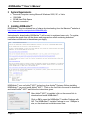
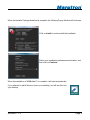
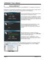
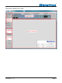
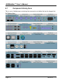
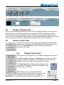
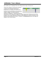
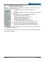
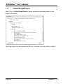
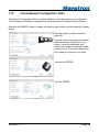
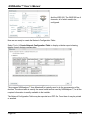
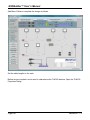
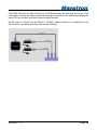
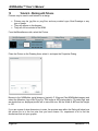
®
N2KBuilder™
NMEA 2000® Network
Design Software
User’s Manual
Revision 1.1.0
Copyright © 2009 Maretron, LLP All Rights Reserved
Maretron, LLP
9014 N. 23rd Ave #10
Phoenix, AZ 85021-7850
http://www.maretron.com
Maretron Manual Part #: M002601
Revision 1.1.0
Page 1
N2KBuilder™ User’s Manual
Table of Contents
1 Introduction ......................................................................................................................... 3 2 System Requirements ........................................................................................................ 4 3 Installing N2KBuilder™....................................................................................................... 4 4 Updating N2KBuilder™ ...................................................................................................... 6 5 Starting N2KBuilder™ ........................................................................................................ 7 6 Screen Layout .................................................................................................................... 8 6.1 Component Library Area ............................................................................................ 10 6.2 Design / Drawing Area ................................................................................................ 11 6.3 Screen Control Area ................................................................................................... 11 6.4 Display Control Area................................................................................................... 11 6.5 Design Rule Check Area ............................................................................................ 13 7 Tutorial 1 – Your First Network ......................................................................................... 14 7.1 Start N2KBuilder™ and Populate the Drawing Area................................................... 14 7.2 Add Detail to the Title Block ....................................................................................... 24 7.3 Add Detail to the Devices ........................................................................................... 24 7.4 Add Detail to the Cables ............................................................................................. 26 7.5 Design Rule Checks and Detail Display ..................................................................... 28 7.6 Displaying the Gender of Connectors ......................................................................... 33 7.7 Adding Lines and Text to the Drawing ........................................................................ 34 7.8 Assigning Instance Numbers ...................................................................................... 35 7.9 Create Bill of Materials Report .................................................................................... 35 7.10 Create Design Rules Check Report............................................................................ 36 7.11 Create Design Report ................................................................................................. 38 7.12 Create Network Configuration Table .......................................................................... 39 7.13 Printing and Exporting the Drawings. ......................................................................... 41 8 Tutorial 2 – Using the Single Ended Cordset .................................................................... 42 9 Tutorial 3 – More Complex Power Options ....................................................................... 44 9.1 Multiple Power Sources .............................................................................................. 44 9.2 Voltage Drops to the PowerTap.................................................................................. 49 10 Tutorial 4 – Extending an Existing Network ................................................................ 51 11 Tutorial 5 – Creating Other Devices ........................................................................... 58 12 Tutorial 6 – Working with Pictures .............................................................................. 60 13 Technical Support....................................................................................................... 63 Page 2
Revision 1.1.0
®
1 Introduction
N2KBuilder™ software is a powerful PC-based tool for designing and verifying the integrity of
NMEA 2000® networks. The N2KBuilder™ software, when installed on a Windows PC and
used as part of an integrated design workflow can be used to layout, document, and validate
the design of complex NMEA 2000® networks. In addition, it will directly produce a Bill of
Materials (BOM) for Maretron products, eliminating guesswork and transcription errors.
Features:
• Pictorial display of all NMEA 2000® devices on the network
• Record a wealth of following information for each device:
o Manufacturer (pre-programmed)
o Manufacturer Model ID (pre-programmed)
o Device Instance
o Device Label
o Manufacturer Serial Number
o Installation Descriptions
o Current requirements in Load Equivalent Number (LEN) and milliamps (preprogrammed)
•
For devices supporting multiple channels, the following information for each device may
be recorded, as appropriate:
o Hardware Channel
o Indicator
o Source
o Instance
o Label
o Connected Probes
•
For devices with ancillary equipment attached, such as probes and cables, property
dialogs allow these to be recorded and included in the BOM.
Produce a detailed drawing in either JPG or PNG format.
Produce a detailed alphabetical Bill of Materials (BOM) with part numbers, descriptions
and quantities.
Produce an N2K Design Rules Check Report to document network errors.
Produce an N2K Design Report to document the design. This can be used in
discussions with clients to logically explain the devices on the Network.
Produce a Network Configuration Table that can be used, in conjunction with
N2KAnalyzer™ by installation and programming teams.
Analyze the devices on the network to ensure that the network complies with the NMEA
2000® standard, and there are no voltage drops or cable lengths that may cause
devices to not function correctly.
Assign Instance Numbers in one quick step.
Update N2KBuilder™ over the internet
•
•
•
•
•
•
•
•
Revision 1.1.0
Page 3
N2KBuilder™ User’s Manual
2 System Requirements
•
•
•
•
Personal Computer running Microsoft Windows 2000, XP, or Vista
1GB RAM
30 MB Hard Disk Space
Internet connection
3 Installing N2KBuilder™
N2KBuilder™ may be obtained free of charge by downloading from the Maretron® website at
http://www.maretron.com/products/n2kbuilder.php
Instructions for downloading N2KBuilder™ will be sent to registered users only. To register,
complete the simple form on the above web page and an email containing download
instructions will be sent to the address you supply.
N2KBuilder™ runs on Adobe® AIR™ technology from Adobe® Systems. Before installing
N2KBuilder™ you must install Adobe® AIR™. Click on the first link in the email to download
and install Adobe® AIR™ and follow the instructions given.
After Adobe® AIR™ is installed, click on the second link to
download and install N2KBuilder™.
Click on OK to open the N2KBuilder™ Installer Package with
AIR. The N2KBuilder™ Installer Package is over 11Mbytes in
size, so the download could take some time.
Page 4
Revision 1.1.0
®
When the Installer Package download is complete, the following Popup Window will be shown.
Click on Install to continue with the installation.
Select your installation preferences and location, and
then click on Continue.
When the installation of N2KBuilder™ is complete, it will start automatically.
If you selected to add a Shortcut icon to your desktop, you will see this icon
your desktop.
Revision 1.1.0
Page 5
N2KBuilder™ User’s Manual
4
Updating N2KBuilder™
To be updated requires that the computer running N2KBuilder™ is connected to the Internet.
N2KBuilder™ will periodically check Maretron’s website for the latest version. If a later version
is found on the server, then the following Popup Window will be displayed.
Click on Download Now, and a new version will be
downloaded from the Maretron® Server.
Having the latest version of N2KBuilder™ installed
on your system will ensure that the components in
the Component Library Area are up to date with the
latest Maretron® catalog.
While the update is being downloaded, you can
view the Release Notes which give some
information about the changes from the previous
release.
When the download is complete, this Popup
Window will be displayed. Click on the Install Now
button to install the new version.
The previous version of N2KBuilder™ will be
automatically closed, and the new version started
with the same file open.
While N2KBuilder™ is running, you may also request that it checks for an update by clicking
on the Check for Updates button under the About
Menu.
Page 6
Revision 1.1.0
®
5
Starting N2KBuilder™
You may start N2KBuilder™ in one of four ways:
• Selecting the All Programs→ N2KBuilder™ item from the Start Menu
• Clicking the quick launch icon, if you requested one to be created during installation
• Clicking the desktop icon, if you requested one to be created during installation
• Clicking on a file with an extension of .n2b. The first time that you do this, Windows will
request that you assign this file type to N2KBuilder™.
The following disclaimer will be displayed when N2KBuilder™ is started.
You will need to Accept the disclaimer before continuing.
Pressing Exit will exit the program.
Revision 1.1.0
Page 7
N2KBuilder™ User’s Manual
6
Screen Layout
When you start N2KBuilder™, you will be presented with the following screen.
Page 8
Revision 1.1.0
®
The screen is divided into 5 areas.
Revision 1.1.0
Page 9
N2KBuilder™ User’s Manual
6.1
Component Library Area
This is a set of tabbed pages containing the components and cables that can be dragged into
the Drawing Area.
Page 10
Revision 1.1.0
®
6.2
Design / Drawing Area
This is the main drawing area where you do all the work. Initially the screen is sized at about
900 x 500 pixels, but it may be extended by zooming out to 10000 x 10000 pixels. If the
Drawing Area is too big to be displayed, then scroll bars will be displayed to allow the visible
area to be moved. Alternatively, right clicking on the grey background of the Drawing Area, and
then moving the mouse with the right button held down will also move the drawing.
6.3
Screen Control Area
These buttons control the zoom level of the Drawing Area. Zoom In will
increase the zoom level by 50%; Zoom Out will decrease the zoom level
by 50%; and Zoom Extents will zoom the design so that all the
components are visible.
6.4
Display Control Area
These buttons control the amount of information displayed on the screen.
The Cable Lengths, Currents, and Voltages buttons display the cable
lengths, currents and voltages next to the components and cables as
appropriate. Only one of these may be displayed at a time.
The Plug Gender button displays the plug gender of the
components. The display of the gender is toggled on and
off by clicking on this button.
After creating a line or a cable, the handles or
junctions (i.e., where the cable or line changes direction) may be moved
by dragging handles displayed at the cable junctions. The Show
Handles button controls whether these handles are displayed or not. If
Revision 1.1.0
Page 11
N2KBuilder™ User’s Manual
the handles are not displayed, then the cable junctions may not be moved.
If there are sufficient components connected
correctly in the drawing to identify the
backbone(s) or trunk(s) of the network, the
backbone may be identified on the drawing by
a green overlay. To correctly identify a
backbone, N2KBuilder™ requires at least two
terminators to be connected via cables and other components. If there are errors in the
backbone (e.g. three terminators) then the overlay will be red. If there is no power to the
backbone, the overlay will be yellow. Clicking on the Backbone(s) button will toggle the
display of the colored overlay.
Page 12
Revision 1.1.0
®
6.5
Design Rule Check Area
N2KBuilder™ continually evaluates the design against a number of rules determined by the
NMEA 2000® standard. These rules are:
• Two and only two terminators per network backbone.
• No loops.
• Power supplied between 9V and 16V in sufficient places to power all
the components.
• Not more than 50 nodes without appropriate repeaters.
• Mini Backbone length less than 200m.
• Mid/Micro Backbone length less than 100m.
• All cables have been assigned a length.
• Branch lengths must not exceed 6m.
• Cumulative branch length must not exceed 78m.
• Currents through each cable and cable component (i.e., tee,
bulkhead feedthru, multiport box, etc) must be within their rating.
• Supply Voltage at each device must be between 9V and 16V.
• Common Mode Voltage at each device must be less than 2.5V.
In addition, a warning is given if all the devices on the display area are not
connected to the backbone.
By pressing the “Show On Drawing” button, the components in the Drawing Area that violate
the rules will be highlighted.
Revision 1.1.0
Page 13
N2KBuilder™ User’s Manual
7
Tutorial 1 – Your First Network
The first network will be a simple navigation system for a small yacht. It will consist of the
following devices, connected using Micro Cables.
• DSM250 Display
• WSO100 Weather Station
• SSC200 Solid State Compass
• GPS200 Global Positioning System.
7.1
Start N2KBuilder™ and Populate the Drawing Area
The initial screen will have a Title Block in the bottom right corner. We will populate this later.
Start populating the Display Area by placing a DSM250. The DSM250 is in the
Displays/Alarms tab in the Component Library Area.
Select the DSM250 by clicking on the symbol. Note that hovering over the symbol will display a
tool tip showing the description of the device, so if you are ever unsure of what a device is …
just hover over it. When the device has been selected, a black glow will be shown around it.
Now move the cursor into the Drawing Area using the mouse. The DSM250 will follow. Press
the left mouse button to drop the device onto the Drawing Area.
Page 14
Revision 1.1.0
®
Notice that there is still a DSM250 following the cursor. This enables you drop another
component of the same type very quickly without having to go back to the Component Library
again. Drop a second DSM250 onto the Drawing Area.
To free the cursor from the device, do one of the following:
• Click on the same component in the Component Library
• Click on the background of the Component Library
• Right Click with the Mouse to bring up a menu, and then click on Cancel with the left
button
• Press the Escape (Esc) key
The following screen shows the screen after dropping 2 DSM250s on the drawing area and
then right-clicking to bring up the component menu on the DSM250 that we are dragging
around.
Revision 1.1.0
Page 15
N2KBuilder™ User’s Manual
Free the cursor so that nothing is following it. We now have two DSM250s on the Drawing
Area, which is one too many. Left click on the rightmost DSM250 to select it (notice the black
glow around the DSM250 which shows that it has been selected) and then right click to show
the component menu.
The component must be selected to respond to the right click.
There are a couple of things that we can do here, but we will
get to them later. For now, click Delete to remove the device
from the Drawing Area.
You could also press the Delete button on your keyboard.
Page 16
Revision 1.1.0
®
Get the rest of the components in the same way. Select the Navigation Instruments tab in the
Component Library Area, and then drag a WSO100, SSC200, and GPS200 onto the Drawing
Area. We are going to put the WSO100 on top of the mast and the GPS200 on the cabin top.
Revision 1.1.0
Page 17
N2KBuilder™ User’s Manual
Next add the PowerTap so that we can get power to the network. We are going to use Micro
cabling, so choose the Micro/Mid Power Tap Tee from the Mid/Micro Cable Components tab in
the Component Library.
Page 18
Revision 1.1.0
®
To terminate the network, we will use a Micro Termination Resistor Male near the DSM250,
and a Micro Inline Termination Resistor connected to the WSO100. Both of these can be found
in the Mid/Micro Cable Components tab of the Components Library Area.
Remember that you can hover over a component to identify it.
Revision 1.1.0
Page 19
N2KBuilder™ User’s Manual
Now we will turn the Micro Inline Termination Resistor around and
connect it to the WSO100. Left click on the Micro
Inline Termination Resistor to select it, and right
click to display the associated menu. The
WSO100 has a male connector; the Micro Inline
Termination Resistor has a female connector on
the left, so click on Rotate Clockwise to get
these connectors oriented towards each other.
To make the connection, move the Micro Inline Termination Resistor by grabbing it with the
mouse and moving it until the plugs line up. (Hold the left mouse button down while moving the
mouse, and then release the mouse button).
Notice the Warning that pops up.
N2KBuilder™ is not designed to draw a physical
representation of your network. While it will ensure that
the connector genders are correct, it will not take into
account any keying of the connectors.
For example, N2KBuilder™ will allow
you to connect 2 Mini Tees together in
the following manner.
While this is logically correct, it is not
physically possible, and the Tees will
actually be joined as shown in the
second diagram.
This will make the layout of your drawing easier, but will not guarantee that the layout of your
drawing matches the physical installation
Now, back to our design … we should have just made the connection between the in-line
terminator and the WSO100.
If you were close, the Micro Inline Termination Resistor will snap into place, and
the components are connected.
Deselect the Micro Inline Termination Resistor by clicking on the background.
Page 20
Revision 1.1.0
®
Drag three Micro Tees from the Mid/Micro Cable Components tab onto the Drawing Area.
Before placing the first Tee just below the DSM250, right click the mouse, and select the Flip
Vertical menu option to correctly orient the Tee. Before placing the second Tee below the
SSC200, right click the mouse and select the Flip Horizontal menu option to correctly orient the
Tee so that the male connector of the Tee faces the female connector of the Power Tap Tee.
Connect the first Tee to the Micro Termination Resistor Male by moving either the Tee or the
Terminator until the plugs line up.
Revision 1.1.0
Page 21
N2KBuilder™ User’s Manual
Last, we will add the cables. Micro connectors can have either Micro or Mid size cabling,
shown in N2KBuilder™ by different thicknesses. Hovering over the cable will also show the
thickness. Cables may also be bought with the connectors attached (Double Ended Cordsets)
or built from Bulk cable with field attachable connectors.
Click on the Micro Double Ended Cordset, which is at the top left of the Mid/Micro Components
tab. Now when the mouse is moved into the Drawing Area, there is a
small connector that follows the mouse cursor. Move the cursor near the
plugs on a Tee. Notice that the connector will change orientation and
gender to match the nearest plug. Move to the rightmost male
connector of the Tee under the DSM250, and when the cable connector
changes to the correct orientation, left click the mouse to connect the
first end of the cable to the Tee.
A second connector, of the opposite gender to the first end of the cable
is now displayed. Move this until it is lined up with the leftmost connector
on the power tap, and make this connection as well.
Repeat this process for all the cables.
If necessary move the components around to neaten up the drawing.
Page 22
Revision 1.1.0
®
Congratulations – you now have your first network in place. Save it by selecting File Æ Save
As and entering a filename in the Save As Dialog. The extension will be set to .n2b.
Revision 1.1.0
Page 23
N2KBuilder™ User’s Manual
7.2
Add Detail to the Title Block
Left click on the title block to select it, and then right click to open the title block menu.
Click on Properties to open the
Properties Dialog for the Title Block.
In this case, the Title Block Properties
Dialog is a replica of the Title Block itself, and it gives us the opportunity to enter some values.
Enter a Title of Tutorial 1.
Add your name to the Drawn box, and
select today’s date for the Drawn Date.
Press the OK button to save these
values.
7.3
Add Detail to the Devices
Left click on the SSC200 to select it, and then right click to open the device menu. Then left
click on the Properties option to open the Properties Dialog. Each device has a different
Properties Dialog; the SSC200 being one of the simplest.
These fields can be found within all device
Property Dialogs, and they are informational
only at this point. By filling in all the fields
early in the design phase, you will create a
record that can be used later during
installation.
If you are connected to the Internet, clicking on the More Information button will use your
default Internet Browser to open a web page showing the full specification of the Device.
Page 24
Revision 1.1.0
®
Open the Property Dialog for the DSM250 – this is a little more interesting.
As well as the standard fields for Device Instance, Device Label, Serial Number, Installation
Descriptions and the Current Drawn, we also show some options that will affect the Bill of
Materials. Change the color to White, and include a Gimbal Mount or extra covers before
selecting the OK button.
Notice that when you get back to your drawing the color of the DSM250 has changed to white.
Revision 1.1.0
Page 25
N2KBuilder™ User’s Manual
7.4
Add Detail to the Cables
Adding detail to the cables is essential to the design verification process. Without accurate
input on how long the cables are, it is impossible to calculate voltage drops.
Right click on the cable running to the WSO100, and select the Properties option. The
following Cable Properties Dialog is displayed.
Assume the distance up the mast is 18m. Prebuilt double ended cordsets are limited to 10m,
and are therefore not suitable for this design. We need to buy 18m of bulk cable, and then
connect a field attachable connector to each end.
To achieve this, change the cable type to a “Field Attachable Cable”. More options will be
displayed.
Type 18 in the Cable Length field.
To help you understand the properties of the
cable that you have just created, N2KBuilder™
will calculate the resistance of one of the power
wires in the cable and display it. This resistance
else includes the internal contact resistance of
the connectors.
Close the Properties Dialog.
Notice that the drawing has changed to show
the Field attachable connectors.
Page 26
Revision 1.1.0
®
Not all Cables are Created Equal
NMEA 2000® is a high speed data bus, similar to Ethernet.
At these speeds, the signals do not travel cleanly from one
end of the cable to the other, but are subject to many
reflections from each connector, branch and cable join.
These reflections cause the signal to degrade significantly,
and at some point the network fails to work.
NMEA have established a set of requirements for NMEA
2000® networks which, when followed, will ensure that the
signals remain strong enough for the messages to get
through. Some of these requirements limit cable lengths
and the number of nodes, and N2KBuilder™ will evaluate
your design to check that these requirements are met.
Other requirements dictate the physical characteristics of
the cabling and connectors to ensure clean signals.
N2KBuilder™ assumes that only NMEA2000® approved
cabling will be used on the network. Use of cabling that
does not meet NMEA 2000® requirements will result in
weaker signals and lower voltages than expected and will
invalidate all the calculations and Design Rule Checks.
It is essential that only NMEA2000® approved cabling and
connectors are used in building NMEA2000® networks.
Revision 1.1.0
Page 27
N2KBuilder™ User’s Manual
7.5
Design Rule Checks and Detail Display
At this point, take a look at the top left of the screen, in the Design Rule
Checks Area, to see how compliant our network is to NMEA 2000®
requirements. We seem to be doing very well.
• The number of terminators correctly checks OK
• The No Loops correctly checks OK
• The Power feed correctly checks OK
• The Number of Nodes or devices correctly checks OK
• There ARE undefined cable lengths – that’s expected – we have
only entered the detail for one cable.
• The trunk length correctly checks OK
• The branch lengths report OK.
• The cumulative branch length reports OK.
• The currents, voltages and common mode voltages report OK.
• All devices are connected to the backbone OK.
Click on the Show On Drawing button so that we can see, on the drawing, which Cable
Lengths are not OK.
Page 28
Revision 1.1.0
®
They are highlighted in red.
Remove the display of the Design Rule Checks Errors by clicking on the Show On Drawing
button again, and then, using the Cable Properties Dialog, set the lengths of the cables as
follows:
• On either side of the Micro Power Tap Tee : 10m
• On the drop to the DSM250 : 1m
• On the drop to the SSC200 : 5m
• On the drop to the GPS200 : 7m
• Between the last two Tees : 30m (make this a Field Attachable Cable)
Display the cable lengths on the drawing by clicking on the Cable Lengths button. To neaten
up the drawing you may need to drag the labels to better places.
In the Design Rules Checks Area, we can see that we now have the Cable Lengths OK, but
have introduced errors in the Branch Lengths and Voltages. Press the Show On Drawing
button to highlight the problems.
The 7m long cable to the GPS200 is the cause of the Branch Length problem, so reduce its
length to 6m, which is the maximum allowed length for a drop.
Revision 1.1.0
Page 29
N2KBuilder™ User’s Manual
Page 30
Revision 1.1.0
®
This leaves the voltage problem. Display the voltages by selecting the Voltages button.
You can also use the mouse to hover over the selected component and get error information.
The cables are too thin to supply enough power to the WSO100 at
the end of the backbone. This is probably a good time to decide to
upgrade the entire network to use Mid cables instead of Micro
cables. We could change each cable using the cable Properties
Dialog, but there is an easier way using the Network Functions of
N2KBuilder™. Right click on any cable in the backbone, and select
the Network Functions option.
The choices given under the Network Functions depend on what
changes can be made to the cable selected. We want to change to
Mid, and that is available. Click on it.
All the cables in the drawing change to Mid, and the voltage at the
WSO100 rises to 11.14V.
Revision 1.1.0
Page 31
N2KBuilder™ User’s Manual
Notice also that the cable thicknesses have changed in the drawing area to reflect this change
to the cables.
Try changing the cable colors to Blue.
Note also that all the Design Rule Checks have now passed.
As a final clean up, select the Tools Menu from
the top list of menus, and then select Snap all
Cables / Lines.
Individual cables can be snapped into 90
degree angles by right clicking on the cable
and selecting the Snap option.
The cables also have handles at their intermediate points which can be dragged
to reposition the intermediate points of the cables. To display the handles, click
on the Cable Handles button on the left of the screen. To hide them, click on the
Cable Handles button a second time.
Page 32
Revision 1.1.0
®
7.6 Displaying the Gender of Connectors
To display the gender of the connectors – this is important for the installer – click on the Plug
Gender button at the left of the screen.
Click on the Plug Gender button a second time to remove the display of the genders.
Revision 1.1.0
Page 33
N2KBuilder™ User’s Manual
7.7 Adding Lines and Text to the Drawing
To make the drawing more readable, add Lines and Text from the Miscellaneous Tab. When
placing a Line on the Drawing Area, select the line in the Component Library and then click in
the Drawing Area where the start of the line should be dropped. Continue clicking to drop the
mid points of the line, and then click twice at the same point to drop the end of the Line.
Once the line has been added, you can open the Line Properties Dialog and change the line
color and thickness.
Page 34
Revision 1.1.0
®
7.8
Assigning Instance Numbers
Instance Numbers may be assigned individually by entering them into the respective Device
Dialog boxes, or N2KBuilder can assign them automatically from the Tools Menu. Or you can
do a combination of both.
First assign any Instance Numbers manually where you want control of what the Instance
Number must be. Click the “lock” check box next to the instance number to prevent these
numbers from being assigned by N2KBuilder.
To have N2KBuilder assign the rest of the Instance Numbers select “Assign Instances” from
the Tools Menu.
7.9
Create Bill of Materials Report
The Bill of Materials (BOM) Report is generated from the Tools Menu.
Selecting Create Bill of Materials Report will bring up the following screen, which can be:
• Exported as a comma separated value (csv) file for importing into Excel or another
program,
Revision 1.1.0
Page 35
N2KBuilder™ User’s Manual
•
•
Exported as a pdf file,
Printed.
Notice the following about the entries in the BOM.
• The two bulk cables have been combined into one length of 38m. Should this length go
over 100m, then a spool of 100m will be ordered, plus the additional cable as a
separate piece.
• The gimbal mount has been included for the DSM250
• The DSM250 has been ordered in a white enclosure.
• 4 field attachable connectors have been included for the bulk cable.
7.10
Create Design Rules Check Report
Select Tools Æ Create Design Rules Check Report to display a textual report showing what
the problems are with the network.
Page 36
Revision 1.1.0
®
The Design Rules Check Report may be exported as a PDF file. From there it may be printed
or emailed.
Revision 1.1.0
Page 37
N2KBuilder™ User’s Manual
7.11
Create Design Report
Select Tools Æ Create Design Report to display a textual report showing details of each
branch in the network.
The Design Report may be exported as a PDF file. From there it may be printed or emailed.
Page 38
Revision 1.1.0
®
7.12
Create Network Configuration Table
The Network Configuration Table is used by installers to set up the devices on the Network.
The information in the table is obtained from the detail entered in Device Property Dialogs.
Start with the DSM250. Select it; display the menu by right clicking, and the open the Property
Dialog.
Enter the values as shown and then
press OK.
Typically, when entering this information,
the serial number of the device is not
known. Leave this field blank, and
request the installer to write the number
on the printout. Then enter it back in the
file to keep your records in one place.
Next do the SSC200.
And the GPS200
Revision 1.1.0
Page 39
N2KBuilder™ User’s Manual
And the WSO100. The WSO100 has 4
channels, all of which need to be
configured.
Now we are ready to create the Network Configuration Table.
Select Tools Æ Create Network Configuration Table to display a tabular report showing
details of each devices configuration.
The program N2KAnalyzer™ from Maretron® is typically used to do the programming of the
devices. The above table is exactly the same format as that used by N2KAnalyzer™, so all the
required information is readily available to the installer.
The Network Configuration Table may be exported as a PDF file. From there it may be printed
or emailed.
Page 40
Revision 1.1.0
®
7.13
Printing and Exporting the Drawings.
The contents of the Drawing Area may be printed and exported as either .jpg files or .png files
from the File menu.
• The Print function will print what is displayed on
the screen. Zoom and pan as required to get the print
contents that you want.
• For exporting as either a jpg or png file, the full
diagram is exported. Png files give better results than
jpg file. After exporting, they can be imported into an
application such as Paint, which will then allow them to
be printed as a set of tiles.
Revision 1.1.0
Page 41
N2KBuilder™ User’s Manual
8
Tutorial 2 – Using the Single Ended Cordset
The Single Ended Cordset is designed to be used for the run up the mast. It is sold as a 25m
mid cable with a female molded connector to go at the top of the mast. The molded connectors
are smaller diameter than the field attachable connectors, and when connected to the Micro
Inline Termination Resistor will fit comfortably within the 1” pipe mount used to mount the
GPS200, GPS200, or WSO100. The other end of the cable without a connector can be cabled
easily through small openings. A male field-attachable connector is required to connect the
Cordset to the network. Because of the length of the cable, the Single Ended Cordset is
intended to be used as part of the network backbone, not as a branch.
In the network designed in tutorial 1, select the cable going to the WSO100, then right click
and open the Cable Properties Dialog.
Select the Single Ended Cordset option.
Page 42
Revision 1.1.0
®
Notice four things:
• The cable size has been restricted to Mid. The Single Ended Cordset is only available
as Mid cable. If the cable was originally a Mini cable, with Mini connectors, then the
option to change the cable type to a Single Ended Cordset would have been disabled.
• The cable color has been restricted to Blue. This cable is only available in Blue.
• The Cable Length has remained at 18m. Although the cable is sold in 25m lengths, it is
intended that the installer will cut the cable to an appropriate length to minimize voltage
drops. The maximum length that can be entered in this field is 25m.
• The options of the female connector have been removed. The female connector is
molded on to the cable, and cannot be changed.
On the diagram, the cable is now drawn with one molded
connector and one field attachable connector.
The field attachable connector is added to the BOM.
Revision 1.1.0
Page 43
N2KBuilder™ User’s Manual
9
Tutorial 3 – More Complex Power Options
9.1
Multiple Power Sources
Using the techniques shown in Tutorial 1, create the following network using N2KBuilder™.
Notes:
• All the trunk cables are 10m Mini overmolded cables.
• All the branch cables are 1m Micro overmolded cables
• All the Tees are Mini-Micro Tees.
Page 44
Revision 1.1.0
®
Click the “Show on Drawing” button which will cause some of the DSM250 displays to be
highlighted in red. Because of the long cables and high current drain, the voltage drops across
the network are too large. We will fix the problem by adding a second PowerTap.
Delete the cable joining DSMs 2 and 3. Also delete the two cables to the left of the break. You
will notice immediately that the terminators glow, showing that the terminators are unmatched,
and the devices glow yellow.
Add a second PowerTap as shown below.
Revision 1.1.0
Page 45
N2KBuilder™ User’s Manual
Notice that the female connector from the PowerTap is facing the female connector of the Tee
to the left. Flip this Tee and the next Tee horizontally to correctly line up the sockets with the
correct genders.
Reconnect the cables. Set their lengths back to 10m.
Page 46
Revision 1.1.0
®
Now connect the last two Tees in the same way. N2KBuilder™ will detect that both sockets are
female, and will use a Field Attachable Cable with two male connectors.
Revision 1.1.0
Page 47
N2KBuilder™ User’s Manual
We have two problems: The new cable has an undefined length, and the two power supplies
are connected to each other.
Open the Cable Properties Dialog for the Cable, and set the length to 10m. We also choose to
break the Power Cables at both ends of this cable so that the power on each half of the
network is isolated from the other half.
Page 48
Revision 1.1.0
®
The result is shown on the drawing as follows:
Our design now passes the Design Rule Checks.
9.2
Voltage Drops to the PowerTap.
Using the previous design, display the voltages on the drawing by clicking on the Voltages
button.
Two voltages are shown for each Mini PowerTap.
The voltage associated with the yellow power cable (12V) is the voltage
at the source.
The voltage above the Mini PowerTap (11.08V) is the voltage that is
supplied to the bus, taking into account the losses in the yellow power
cable and in the Mini PowerTap.
Open the Properties Dialog for the Mini PowerTap.
Revision 1.1.0
Page 49
N2KBuilder™ User’s Manual
The Power Cable is supplied in one of two lengths, 1m or 5m. The top selection is used to
choose which option is included in the BOM.
To reduce voltage drops, this cable may be cut to length during installation, or even
lengthened. If it is lengthened, the Design Rule Checker will assume that the cable used for
the extension has similar characteristics as the supplied yellow cable (i.e. 16AWG and 13mΩ /
m)
The total length of the cable from the source to the PowerTap should be entered in the Power
Cable Feed Length box.
Change the Included Power Cable to 1m. The Power Cable Feed Length changes to 1m to
match. Click OK.
The voltage to the network has risen by 0.2V.
Page 50
Revision 1.1.0
®
10
Tutorial 4 – Extending an Existing Network
Using the design from Tutorial 3, we will add two Tank Level Monitors so that we can see the
levels of the fuel tanks. These are the TLM100 devices from the Engine/Vessel Monitoring tab.
Open the file from Tutorial 3, and exclude the entire design from being in the BOM.
The result is that all the components are given faded colors to show that they will be excluded
from the BOM in future.
Revision 1.1.0
Page 51
N2KBuilder™ User’s Manual
Drag two TLM100 devices and a Multiport Box from the Mid/Micro Cable Components tab. Flip
the Multipoint Box horizontally to give the following result.
Page 52
Revision 1.1.0
®
Now select and drag the terminator to the right.
A cable will appear to keep the connection.
Delete the Cable.
Add another Mini/Micro Tee
Drag the terminator back to connect to the new Tee and complete
the backbone.
Revision 1.1.0
Page 53
N2KBuilder™ User’s Manual
Add Micro Cables to complete the design as follows.
Set the cable lengths to 2m each.
Before we are complete, we do need to characterize the TLM100 devices. Open the TLM100
Properties Dialog.
Page 54
Revision 1.1.0
®
Change the mounting to a 1.5” NPT threaded opening. This mounting requires a special
adapter, and this will be included in the BOM.
Set the Device Label to “Port Tank”, and the Device Instance to “0”. As this is a tank for diesel,
also set the Channel Parameters to “Fuel”, the Data Instance to “0” and the Data Label to “Port
Diesel Tank”. We will also order a Focus Tube for the tank.
Planning these details early will help the installer, and provide a record of the details of the
design. The label of each device will be shown in the Tool Tip text displayed when the mouse
hovers over the device in the Drawing Area.
Revision 1.1.0
Page 55
N2KBuilder™ User’s Manual
Set up the starboard tank in the same way, with a 1.5” NPT threaded mounting, a Device Label
of “Starboard Tank”, and a Device Instance of “1”. Set the Channel Parameters to “Fuel”, the
Data Instance to “1” and the Data Label to “Starboard Diesel Tank”. We will also order a Focus
Tube for the tank.
Page 56
Revision 1.1.0
®
If we now generate the BOM, we will see that only the new components are on the page.
Revision 1.1.0
Page 57
N2KBuilder™ User’s Manual
11
Tutorial 5 – Creating Other Devices
Devices that are not pre-populated in the Component Library Area may be added to the
design.
•
•
•
They will be included in all the Design Rule Checks
They will appear on the diagram.
They will not be included in the BOM.
From the Miscellaneous tab, select the Generic Device.
The Generic Device is initially shown with “?”.
Place the device on the Drawing Area, and open the Properties Dialog.
The Manufacturer and Name are two string fields that can be set to any value by the user. The
name will be displayed in the center of the device when displayed in the drawing area, and in
reports.
The LEN and Current Fields are dependent on each other. The values entered are critical to
the accuracy of the Design Rule Checker. Always enter the maximum values. Changing one of
these values will cause the other to be updated when the cursor is moved to another field.
Page 58
Revision 1.1.0
®
The PGNs field must be filled with the list of PGNs that carry the data from the device. This
information is use by the Instance Number Assigner to ensure that two devices generating the
same PGN do not have the same Device Instance Number.
Set the name to “Gizmo” and the LEN to 3 (150mA). Attach the device to a backbone, show
the currents on the drawing and you will see the following:
Revision 1.1.0
Page 59
N2KBuilder™ User’s Manual
12
Tutorial 6 – Working with Pictures
Pictures may be used to add interest to a design.
•
•
•
Pictures may be .jpg files or .png files, and may contain Logos, Boat Drawings or any
type of Image.
They will appear on the diagram.
They will not be included in the BOM.
From the Miscellaneous tab, select the Picture.
Place the Picture on the Drawing Area, select it, and open the Properties Dialog.
Browse to the N2KBuilder install directory (typically C:\Program Files\N2KBuilder\images) and
select the Maretron-Logo-400x75.jpg file. This image is 400 pixels wide by 75 pixels high, and
we decide that our displayed picture will to twice this size. Set the Width to 800 and the Height
to 150.
If you are unsure of what dimensions to enter, the preview area within the Dialog will show how
the picture fits in to the box size that you have chosen. So, experiment a bit to find the
dimensions that suit your graphic.
Page 60
Revision 1.1.0
®
Press OK to save the Picture, and see the result on
the drawing area.
If the size needs tweaking, go back into the Picture
Properties Dialog and change the Width and the
Height.
Here we see the result of having a height that is too
large. The image occupies only the top of the box.
Note: The picture file (.jpg or .png) will NOT be saved within the design file (.n2b). Only the
relative path and filename to the graphic file is saved. If the design file is moved to another
directory (or emailed to another computer) the picture file must be moved (or emailed) as well.
It is suggested that all picture files are stored in the same directory as the design file. When
emailing, zip up the entire directory and then unzip all the files on the destination computer.
Revision 1.1.0
Page 61
N2KBuilder™ User’s Manual
If the link to the picture is incorrect, the following will be shown on the display area.
Clicking anywhere within the border will select the Picture, which can then be edited and the
correct picture file chosen.
Page 62
Revision 1.1.0
®
13
Technical Support
If you require technical support for Maretron products, you can reach us in any of the following
ways:
Telephone: 1-866-550-9100
Fax: 1-602-861-1777
E-mail: [email protected]
World Wide Web: http://www.maretron.com
Mail: Maretron, LLP
Attn: Technical Support
9014 N. 23rd Ave Suite 10
Phoenix, AZ 85021 USA
Revision 1.1.0
Page 63