1
SAFETY PRECAUTIONS
(Please read these instructions before using this equipment.)
Before using this product, please read this manual and the relevant manuals introduced in this manual
carefully and pay full attention to safety to handle the product correctly.
These precautions apply only to this product.
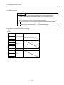
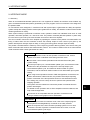
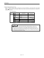
In this manual, the safety instructions are ranked as "DANGER" and "CAUTION".
DANGER
Indicates that incorrect handling may cause hazardous
conditions, resulting in death or severe injury.
CAUTION
Indicates that incorrect handling may cause hazardous
conditions, resulting in medium or slight personal injury or
physical damage.
CAUTION may also be linked to serious
Depending on circumstances, procedures indicated by
results.
In any case, it is important to follow the directions for usage.
Please save this manual to make it accessible when required and always forward it to the end user.
A-1
For Safe Operations
1. Prevention of electric shocks
DANGER
Never open the front case or terminal covers of the servo amplifier while the power is ON or the
unit is running, as this may lead to electric shocks.
Never run the unit with the front case or terminal cover of the servo amplifier removed. The high
voltage terminal and charged sections will be exposed and may lead to electric shocks.
Never open the front case or terminal cover of the servo amplifier at times other than wiring work
or periodic inspections even if the power is OFF. The insides of the position board and servo
amplifier are charged and may lead to electric shocks.
Completely turn off the externally supplied power used in the system before mounting or
removing the position board, performing wiring work, or inspections. Failing to do so may lead to
electric shocks.
When performing wiring work or inspections, turn the power OFF, wait at least ten minutes, and
then check the voltage with a tester, etc. Failing to do so may lead to electric shocks.
Be sure to ground the controller incorporating the position board, servo amplifier and servo
motor. (Ground resistance : 100 or less) Do not ground commonly with other devices.
The wiring work and inspections must be done by a qualified technician.
Wire the units after installing the position board, servo amplifier and servo motor. Failing to do so
may lead to electric shocks or damage.
Never operate the switches with wet hands, as this may lead to electric shocks.
Do not damage, apply excessive stress, place heavy things on or sandwich the cables, as this
may lead to electric shocks.
Do not touch the position board, servo amplifier or servo motor terminal blocks while the power is
ON, as this may lead to electric shocks.
Do not touch the built-in power supply, built-in grounding or signal wires of the position board
and servo amplifier, as this may lead to electric shocks.
2. For fire prevention
CAUTION
Install the position board, servo amplifier, servo motor and regenerative resistor on incombustible.
Installing them directly or close to combustibles will lead to fire.
If a fault occurs in the position board or servo amplifier, shut the power OFF at the servo
amplifier’s power source. If a large current continues to flow, fire may occur.
When using a regenerative resistor, shut the power OFF with an error signal. The regenerative
resistor may abnormally overheat due to a fault in the regenerative transistor, etc., and may lead
to fire.
Always take heat measures such as flame proofing for the inside of the control panel where the
servo amplifier or regenerative resistor is installed and for the wires used. Failing to do so may
lead to fire.
Do not damage, apply excessive stress, place heavy things on or sandwich the cables, as this
may lead to fire.
A-2
3. For injury prevention
CAUTION
Do not apply a voltage other than that specified in this manual and the instruction manual of the
product you are using on any terminal.
Doing so may lead to destruction or damage.
Do not mistake the terminal connections, as this may lead to destruction or damage.
Do not mistake the polarity ( + / - ), as this may lead to destruction or damage.
Do not touch the heat radiating fins of position board or servo amplifier, regenerative resistor and
servo motor, etc., while the power is ON and for a short time after the power is turned OFF. In this
timing, these parts become very hot and may lead to burns.
Always turn the power OFF before touching the servo motor shaft or coupled machines, as these
parts may lead to injuries.
Do not go near the machine during test operations or during operations such as teaching.
Doing so may lead to injuries.
4. Various precautions
Strictly observe the following precautions.
Mistaken handling of the unit may lead to faults, injuries or electric shocks.
(1) System structure
CAUTION
Always install a leakage breaker on the controller incorporating the position board and servo
amplifier power source.
If installation of an electromagnetic contactor for power shut off during an error, etc., is specified in
the instruction manual for the servo amplifier, etc., always install the electromagnetic contactor.
Install the emergency stop circuit externally so that the operation can be stopped immediately and
the power shut off.
Use the position board, servo amplifier, servo motor and regenerative resistor with the correct
combinations listed in the instruction manual. Other combinations may lead to fire or faults.
If safety standards (ex., robot safety rules, etc.,) apply to the system using the position board,
servo amplifier and servo motor, make sure that the safety standards are satisfied.
Construct a safety circuit externally of the position board or servo amplifier if the abnormal
operation of the position board or servo amplifier differ from the safety directive operation in the
system.
In systems where coasting of the servo motor will be a problem during the forced stop, emergency
stop, servo OFF or power supply OFF, use dynamic brakes.
Make sure that the system considers the coasting amount even when using dynamic brakes.
In systems where perpendicular shaft dropping may be a problem during the forced stop,
emergency stop, servo OFF or power supply OFF, use both dynamic brakes and electromagnetic
brakes.
A-3
CAUTION
The dynamic brakes must be used only on errors that cause the forced stop, emergency stop, or
servo OFF. These brakes must not be used for normal braking.
The brakes (electromagnetic brakes) assembled into the servo motor are for holding applications,
and must not be used for normal braking.
The system must have a mechanical allowance so that the machine itself can stop even if the
stroke limits switch is passed through at the max. speed.
Use wires and cables that have a wire diameter, heat resistance and bending resistance
compatible with the system.
Use wires and cables within the length of the range described in the instruction manual.
The ratings and characteristics of the parts (other than position board, servo amplifier and servo
motor) used in a system must be compatible with the position board, servo amplifier and servo
motor.
Install a cover on the shaft so that the rotary parts of the servo motor are not touched during
operation.
There may be some cases where holding by the electromagnetic brakes is not possible due to the
life or mechanical structure (when the ball screw and servomotor are connected with a timing belt,
etc.). Install a stopping device to ensure safety on the machine side.
(2) Parameter settings and programming
CAUTION
Set the parameter values to those that are compatible with the position board, servo amplifier,
servo motor and regenerative resistor model and the system application. The protective functions
may not function if the settings are incorrect.
The regenerative resistor model and capacity parameters must be set to values that conform to
the operation mode and servo amplifier. The protective functions may not function if the settings
are incorrect.
Set the mechanical brake output and dynamic brake output validity parameters to values that are
compatible with the system application. The protective functions may not function if the settings
are incorrect.
Set the stroke limit input validity parameter to a value that is compatible with the system
application. The protective functions may not function if the setting is incorrect.
Set the servo motor encoder type (increment, absolute position type, etc.) parameter to a value
that is compatible with the system application. The protective functions may not function if the
setting is incorrect.
Set the servo motor capacity and type (standard, low-inertia, flat, etc.) parameter to values that
are compatible with the system application. The protective functions may not function if the
settings are incorrect.
Set the servo amplifier capacity and type parameters to values that are compatible with the
system application. The protective functions may not function if the settings are incorrect.
Use the program commands for the program with the conditions specified in the instruction
manual.
A-4
(3) Transportation and installation
CAUTION
Transport the product with the correct method according to the mass.
Use the servo motor suspension bolts only for the transportation of the servo motor. Do not
transport the servo motor with machine installed on it.
Do not stack products past the limit.
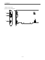
When transporting, installing, and removing the position board, never touch the print board
inner part and electronic components. Hold the front panel or edge of the print board.
When transporting the position board or servo amplifier, never hold the connected wires or
cables.
When transporting the servo motor, never hold the cables, shaft or detector.
When transporting the position board or servo amplifier, never hold the front case as it may fall
off.
When transporting, installing or removing the position board or servo amplifier, never hold the
edges.
Install the unit according to the instruction manual in a place where the mass can be withstood.
Do not get on or place heavy objects on the product.
Always observe the installation direction.
Mount the position board to a connector or slot that is compatible with standards, and keep the
designated clearance between the position board and other boards.
Keep the designated clearance between the position board or servo amplifier and control panel
inner surface or the position board and servo amplifier, position board or servo amplifier and
other devices.
Do not install or operate position board, servo amplifiers or servo motors that are damaged or
that have missing parts.
Do not block the intake/outtake ports of the servo amplifier and servo motor with cooling fan.
Do not allow conductive matter such as screw or cutting chips or combustible matter such as oil
enter the position board, servo amplifier or servo motor.
The position board, servo amplifier and servo motor are precision machines, so do not drop or
apply strong impacts on them.
Securely fix the position board, servo amplifier and servo motor to the machine according to the
instruction manual. If the fixing is insufficient, these may come off during operation.
A-5
CAUTION
Always install the servo motor with reduction gears in the designated direction. Failing to do so
may lead to oil leaks.
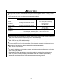
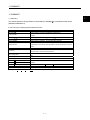
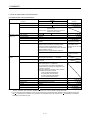
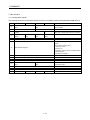
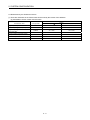
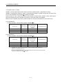
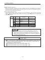
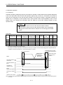
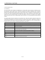
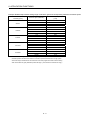
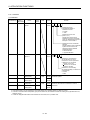
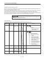
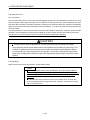
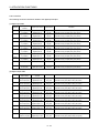
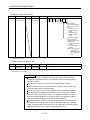
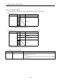
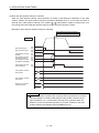
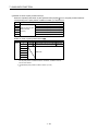
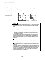
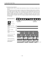
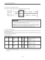
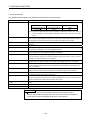
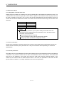
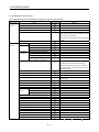
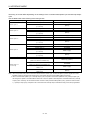
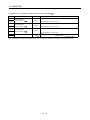
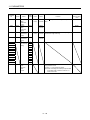
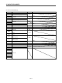
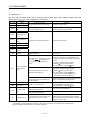
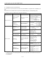
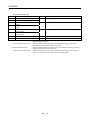
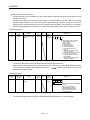
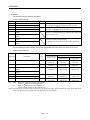
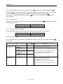
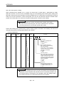
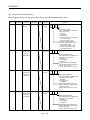
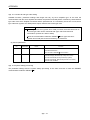
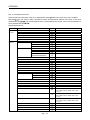
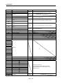
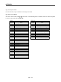
Store and use the unit in the following environmental conditions.
Environment
Ambient
temperature
Ambient humidity
Storage
temperature
Atmosphere
Altitude
Vibration
Conditions
Position board/Servo amplifier
According to each instruction manual.
According to each instruction manual.
According to each instruction manual.
Servomotor
0°C to +40°C (With no freezing)
(32°F to +104°F)
80% RH or less
(With no dew condensation)
-20°C to +65°C
(-4°F to +149°F)
Indoors (where not subject to direct sunlight).
No corrosive gases, flammable gases, oil mist or dust must exist
1000m (3280.84ft.) or less above sea level
According to each instruction manual
When coupling with the synchronous encoder or servo motor shaft end, do not apply impact such
as by hitting with a hammer. Doing so may lead to detector damage.
Do not apply a load larger than the tolerable load onto the synchronous encoder and servo motor
shaft. Doing so may lead to shaft breakage.
When not using for a long time, disconnect the power line from the servo amplifier.
Place the position board and servo amplifier in static electricity preventing vinyl bags and store.
When storing for a long time, please contact with our sales representative.
Also, execute a trial operation.
When fumigants that contain halogen materials such as fluorine, chlorine, bromine, and iodine
are used for disinfecting and protecting wooden packaging from insects, they cause malfunction
when entering our products.
Please take necessary precautions to ensure that remaining materials from fumigant do not
enter our products, or treat packaging with methods other than fumigation (heat method).
Additionally, disinfect and protect wood from insects before packing products.
A-6
(4) Wiring
CAUTION
Correctly and securely wire the wires. Reconfirm the connections for mistakes and the terminal
screws for tightness after wiring. Failing to do so may lead to run away of the servo motor.
After wiring, install the protective covers such as the terminal covers to the original positions.
Do not install a phase advancing capacitor, surge absorber or radio noise filter (option FR-BIF)
on the output side of the servo amplifier.
Correctly connect the output side (terminal U, V, W) and ground. Incorrect connections will lead
the servo motor to operate abnormally.
Do not connect a commercial power supply to the servo motor, as this may lead to trouble.
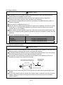
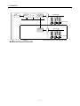
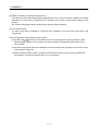
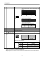
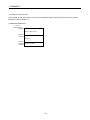
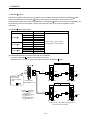
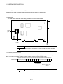
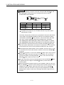
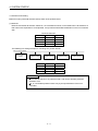
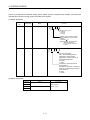
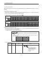
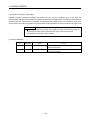
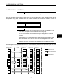
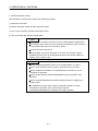
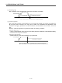
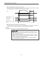
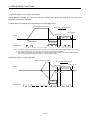
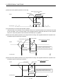
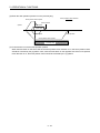
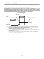
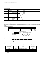
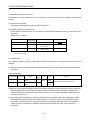
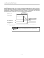
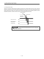
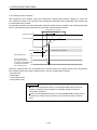
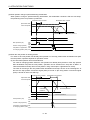
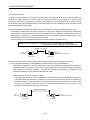
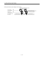
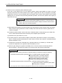
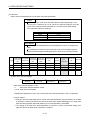
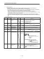
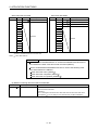
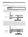
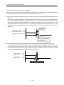
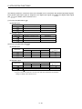
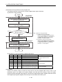
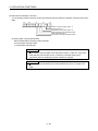
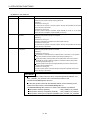
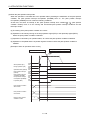
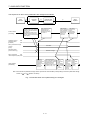
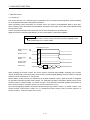
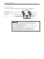
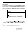
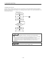
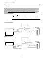
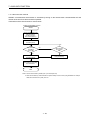
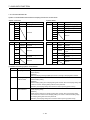
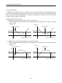
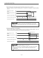
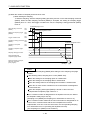
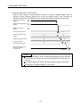
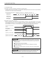
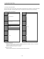
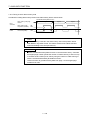
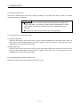
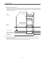
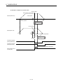
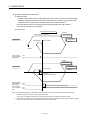
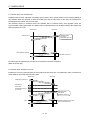
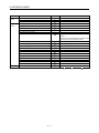
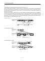
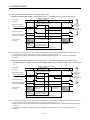
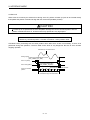
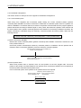
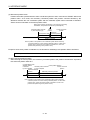
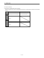
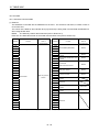
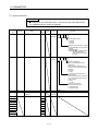
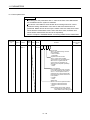
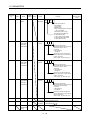
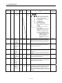
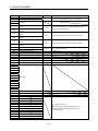
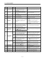
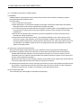
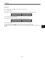
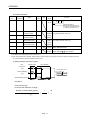
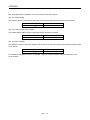
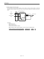
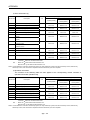
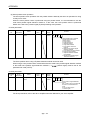
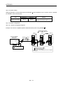
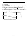
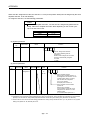
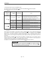
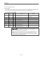
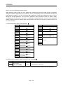
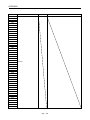
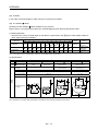
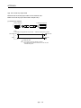
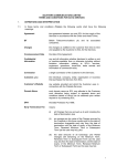
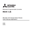
Do not mistake the direction of the surge absorbing diode installed on the DC relay for the control
signal output of brake signals, etc. Incorrect installation may lead to signals not being output
when trouble occurs or the protective functions not functioning.
Servo amplifier
DOCOM
Control output
signal
Servo amplifier
24VDC
DOCOM
Control output
signal
RA
DICOM
24VDC
RA
DICOM
For the sink output interface
For the source output interface
Do not connect or disconnect the connection cables between each unit or the encoder cable
while the power is ON.
Securely tighten the cable connector fixing screws and fixing mechanisms. Insufficient fixing may
lead to the cables coming off during operation.
Do not bundle the power line or cables.
(5) Trial operation and adjustment
CAUTION
Confirm and adjust the program and each parameter before operation. Unpredictable
movements may occur depending on the machine.
Extreme adjustments and changes may lead to unstable operation, so never make them.
When using the absolute position system function, on starting up, and when the position board
or absolute value motor has been replaced, always perform a home position return.
Before starting test operation, set the parameter speed limit value to the slowest value, and
make sure that operation can be stopped immediately by the forced stop, etc. if a hazardous
state occurs.
A-7
(6) Usage methods
CAUTION
Immediately turn OFF the power if smoke, abnormal sounds or odors are emitted from the
position board, servo amplifier or servo motor.
Always execute a test operation before starting actual operations after the program or
parameters have been changed or after maintenance and inspection.
Do not attempt to disassemble and repair the units excluding a qualified technician whom our
company recognized.
Do not make any modifications to the unit.
Keep the effect or electromagnetic obstacles to a minimum by installing a noise filter or by using
wire shields, etc. Electromagnetic obstacles may affect the electronic devices used near the
position board or servo amplifier.
When using the CE Mark-compliant equipment, refer to this manual for the position boards and
refer to the corresponding EMC guideline information for the servo amplifiers, inverters and other
equipment.
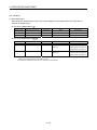
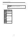
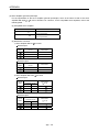
Use the units with the following conditions.
Item
Conditions
Input power
According to each instruction manual.
Input frequency
According to each instruction manual.
Tolerable momentary power failure
According to each instruction manual.
(7) Corrective actions for errors
CAUTION
If an error occurs in the self diagnosis of the position board or servo amplifier, confirm the check
details according to the instruction manual, and restore the operation.
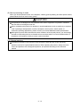
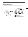
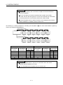
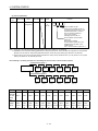
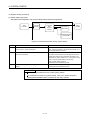
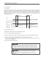
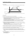
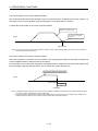
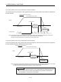
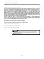
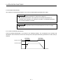
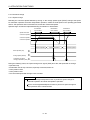
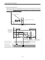
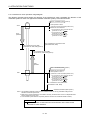
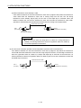
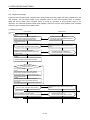
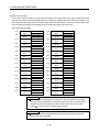
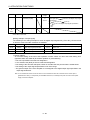
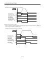
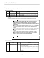
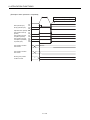
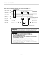
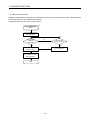
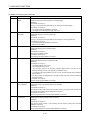
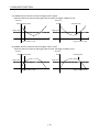
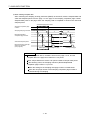
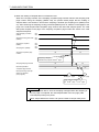
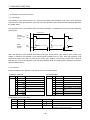
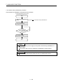
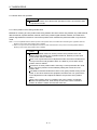
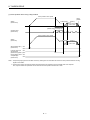
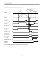
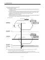
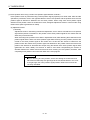
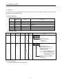
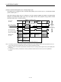
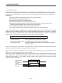
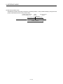
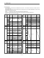
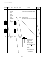
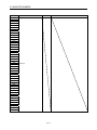
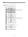
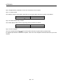
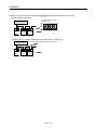
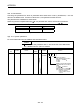
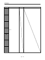
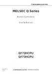
If a dangerous state is predicted in case of a power failure or product failure, use a servo motor
with electromagnetic brakes or install a brake mechanism externally.
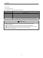
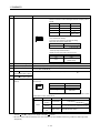
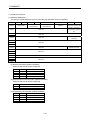
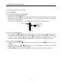
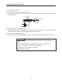
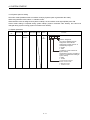
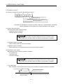
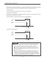
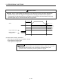
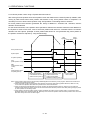
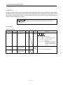
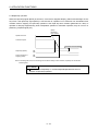
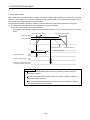
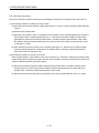
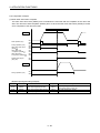
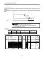
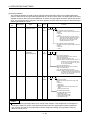
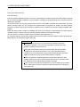
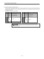
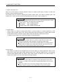
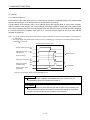
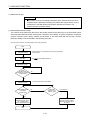
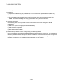
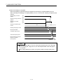
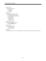
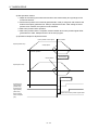
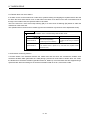
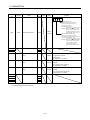
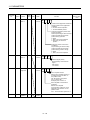
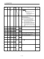
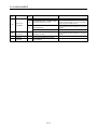
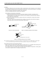
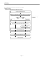
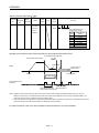
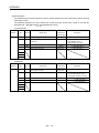
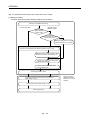
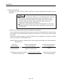
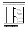
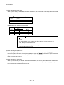
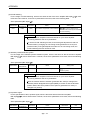
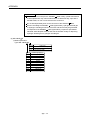
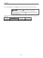
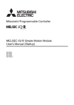
Use a double circuit construction so that the electromagnetic brake operation circuit can be
operated by emergency stop signals set externally.
Shut off with servo ON signal OFF,
alarm, electromagnetic brake signal.
Servo motor
RA1
Electromagnetic
B
brakes
Shut off with the
emergency stop
signal (EMG).
EMG
24VDC
If an error occurs, remove the cause, secure the safety and then resume operation after alarm
release.
The unit may suddenly resume operation after a power failure is restored, so do not go near the
machine. (Design the machine so that personal safety can be ensured even if the machine
restarts suddenly.)
A-8
(8) Maintenance, inspection and part replacement
CAUTION
Perform the daily and periodic inspections according to the instruction manual.
Perform maintenance and inspection after backing up the program and parameters for the
position board and servo amplifier.
Do not place fingers or hands in the clearance when opening or closing any opening.
Periodically replace consumable parts such as batteries according to the instruction manual.
Do not touch the lead sections such as ICs or the connector contacts.
Before touching the position board, always touch grounded metal, etc. to discharge static
electricity from human body. Failure to do so may cause the position board to fail or malfunction.
Do not directly touch the position board's conductive parts and electronic components.
Touching them could cause an operation failure or give damage to the position board.
Do not place the position board or servo amplifier on metal that may cause a power leakage or
wood, plastic or vinyl that may cause static electricity buildup.
Do not perform a megger test (insulation resistance measurement) during inspection.
When replacing the position board or servo amplifier, always set the new position board
settings correctly.
When the position board or absolute value motor has been replaced, carry out a home position
return operation from the user program. Failing to do so may cause position displacement.
After maintenance and inspections are completed, confirm that the position detection of the
absolute position detector function is correct.
Do not drop or impact the battery installed to the module.
Doing so may damage the battery, causing battery liquid to leak in the battery. Do not use the
dropped or impacted battery, but dispose of it.
Do not short circuit, charge, overheat, incinerate or disassemble the batteries.
The electrolytic capacitor will generate gas during a fault, so do not place your face near the
position board or servo amplifier.
The electrolytic capacitor and fan will deteriorate. Periodically replace these to prevent secondary
damage from faults. Replacements can be made by our sales representative.
Lock the control panel and prevent access to those who are not certified to handle or install
electric equipment.
Do not burn or break a position board and servo amplifier. Doing so may cause a toxic gas.
A-9
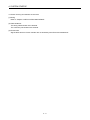
(9) About processing of waste
When you discard position board, servo amplifier, a battery (primary battery) and other option articles,
please follow the law of each country (area).
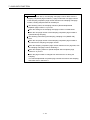
CAUTION
This product is not designed or manufactured to be used in equipment or systems in situations
that can affect or endanger human life.
When considering this product for operation in special applications such as machinery or systems
used in passenger transportation, medical, aerospace, atomic power, electric power, or
submarine repeating applications, please contact your nearest Mitsubishi sales representative.
Although this product was manufactured under conditions of strict quality control, you are strongly
advised to install safety devices to forestall serious accidents when it is used in facilities where a
breakdown in the product is likely to cause a serious accident.
(10) General cautions
All drawings provided in the instruction manual show the state with the covers and safety
partitions removed to explain detailed sections. When operating the product, always return the
covers and partitions to the designated positions, and operate according to the instruction
manual.
A - 10
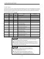
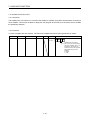
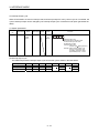
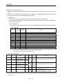
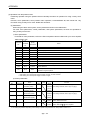
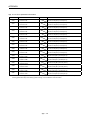
REVISIONS
The manual number is given on the bottom left of the back cover.
Print Date
Dec., 2013
Manual Number
IB(NA)-0300223-A First edition
Revision
Japanese Manual Number IB(NA)-0300222
This manual confers no industrial property rights or any rights of any other kind, nor does it confer any patent
licenses. Mitsubishi Electric Corporation cannot be held responsible for any problems involving industrial property
rights which may occur as a result of using the contents noted in this manual.
© 2013 MITSUBISHI ELECTRIC CORPORATION
A - 11
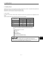
INTRODUCTION
Thank you for choosing the Mitsubishi position board MR-MC210/MR-MC211.
Before using the equipment, please read this manual carefully to develop full familiarity with the functions
and performance of the position board you have purchased, so as to ensure correct use.
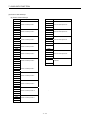
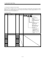
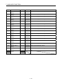
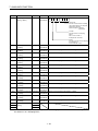
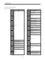
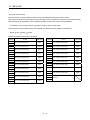
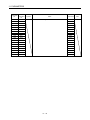
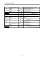
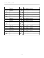
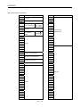
CONTENTS
Safety Precautions .........................................................................................................................................A- 1
Revisions ........................................................................................................................................................A-11
Contents .........................................................................................................................................................A-12
About Manuals................................................................................................................................................A-20
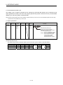
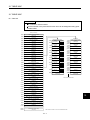
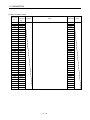
1. SUMMARY
1- 1 to 1-20
1.1 Summary ................................................................................................................................................... 1- 1
1.2 Features of MR-MC21 ........................................................................................................................... 1- 4
1.3 Specifications ............................................................................................................................................ 1- 7
1.3.1 General specifications ........................................................................................................................ 1- 7
1.3.2 List of specifications of position board ............................................................................................... 1- 8
1.4 Name of each section .............................................................................................................................. 1-10
1.5 Bus interface............................................................................................................................................. 1-14
1.5.1 Configuration register ........................................................................................................................ 1-14
1.5.2 Dual port memory map...................................................................................................................... 1-15
1.5.3 Module information ............................................................................................................................ 1-16
1.6 SSCNET cables .................................................................................................................................... 1-18
1.7 Forced stop input terminal ....................................................................................................................... 1-19
2. SYSTEM CONFIGURATION
2- 1 to 2- 6
2.1 MR-MC210 system configuration ............................................................................................................. 2- 1
2.2 MR-MC211 system configuration ............................................................................................................. 2- 2
2.3 System configuration equipment .............................................................................................................. 2- 3
2.4 Checking serial number and operating system software version ............................................................ 2- 4
2.4.1 Checking serial number ..................................................................................................................... 2- 4
2.4.2 Checking software version ................................................................................................................. 2- 4
2.5 Restrictions by the Software's Version ..................................................................................................... 2- 5
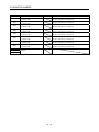
3. INSTALLATION AND WIRING
3- 1 to 3- 6
3.1 Board installation ....................................................................................................................................... 3- 1
3.1.1 Instructions for handling ..................................................................................................................... 3- 1
3.1.2 Installation environment ..................................................................................................................... 3- 1
3.2 Connection and disconnection of cable.................................................................................................... 3- 2
3.2.1 SSCNET cable ................................................................................................................................ 3- 2
3.2.2 Forced stop input cable ...................................................................................................................... 3- 6
4. SYSTEM STARTUP
4- 1 to 4-18
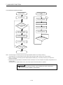
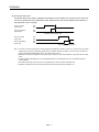
4.1 Startup procedures .................................................................................................................................... 4- 1
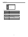
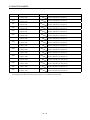
A - 12
4.2 Check of wiring and ambient environment ............................................................................................... 4- 2
4.3 Position board setting................................................................................................................................ 4- 3
4.4 Servo amplifier setting............................................................................................................................... 4- 4
4.5 Parameter setting ...................................................................................................................................... 4- 6
4.5.1 Parameter initialization ....................................................................................................................... 4- 6
4.5.2 System option 1 setting ...................................................................................................................... 4- 7
4.5.3 System option 2 setting ...................................................................................................................... 4- 9
4.5.4 Control option 1 setting ..................................................................................................................... 4-10
4.5.5 Axis No. assignment.......................................................................................................................... 4-11
4.5.6 Sensor input option setting................................................................................................................ 4-13
4.5.7 Vendor ID and type code setting ...................................................................................................... 4-16
4.6 System startup processing ...................................................................................................................... 4-17
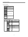
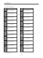
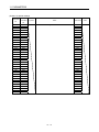
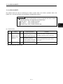
5. OPERATIONAL FUNCTIONS
5- 1 to 5-40
5.1 JOG operation ........................................................................................................................................... 5- 2
5.1.1 Summary ............................................................................................................................................ 5- 2
5.1.2 Start operation method....................................................................................................................... 5- 2
5.1.3 Resuming operation ........................................................................................................................... 5- 3
5.2 Incremental feed........................................................................................................................................ 5- 4
5.2.1 Summary ............................................................................................................................................ 5- 4
5.2.2 Start operation method....................................................................................................................... 5- 5
5.3 Automatic operation .................................................................................................................................. 5- 6
5.3.1 Summary ............................................................................................................................................ 5- 6
5.3.2 Start operation method....................................................................................................................... 5- 7
5.3.3 Auxiliary command ............................................................................................................................. 5- 8
5.3.4 Other axes start specification............................................................................................................ 5-15
5.3.5 S-curve ratio ...................................................................................................................................... 5-15
5.4 Linear interpolation ................................................................................................................................... 5-16
5.4.1 Summary ........................................................................................................................................... 5-16
5.4.2 Settings .............................................................................................................................................. 5-18
5.4.3 Start operation method...................................................................................................................... 5-19
5.4.4 Processing for exceeding speed limit for each axis ......................................................................... 5-20
5.4.5 Restrictions ........................................................................................................................................ 5-21
5.5 Home position return ................................................................................................................................ 5-22
5.5.1 Summary ........................................................................................................................................... 5-22
5.5.2 Start operation method...................................................................................................................... 5-24
5.5.3 Home position return using a dog method ....................................................................................... 5-26
5.5.4 Home position return using a data set method ................................................................................ 5-28
5.5.5 Home position return using a stopper method ................................................................................. 5-28
5.5.6 Home position return using a dog cradle method ............................................................................ 5-29
5.5.7 Home position return using a limit switch combined method........................................................... 5-31
5.5.8 Home position return using a limit switch front end method ............................................................ 5-31
5.5.9 Home position return using a dog front end method ........................................................................ 5-32
5.5.10 Home position return using a Z-phase detection method .............................................................. 5-34
5.5.11 Home position return using a scale home position signal detection method ................................ 5-37
5.5.12 Home position return using a scale home position signal detection method 2 ............................. 5-38
5.6 Home position reset function (data set function)..................................................................................... 5-39
A - 13
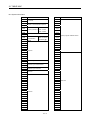
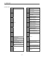
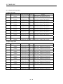
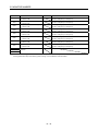
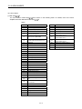
6. APPLICATION FUNCTIONS
6- 1 to 6-102
6.1 Command units ......................................................................................................................................... 6- 1
6.1.1 Position command unit - electronic gear ........................................................................................... 6- 1
6.1.2 Settings ............................................................................................................................................... 6- 3
6.1.3 Setting example of electronic gears .................................................................................................. 6- 3
6.1.4 Restrictions ......................................................................................................................................... 6- 4
6.2 Speed unit ................................................................................................................................................. 6- 5
6.2.1 Settings ............................................................................................................................................... 6- 5
6.2.2 Setting example of speed units .......................................................................................................... 6- 6
6.2.3 Speed limit .......................................................................................................................................... 6- 6
6.3 Acceleration/deceleration.......................................................................................................................... 6- 7
6.3.1 Linear acceleration/deceleration ........................................................................................................ 6- 7
6.3.2 Smoothing filter................................................................................................................................... 6- 8
6.3.3 Start up speed validity ........................................................................................................................ 6- 8
6.3.4 S-curve acceleration/deceleration (Sine acceleration/deceleration) ................................................ 6- 9
6.4 Servo off ................................................................................................................................................... 6-13
6.5 Forced stop............................................................................................................................................... 6-14
6.6 Stop operation .......................................................................................................................................... 6-15
6.7 Rapid stop operation ................................................................................................................................ 6-16
6.8 Limit switch (stroke end) .......................................................................................................................... 6-17
6.9 Software limit ............................................................................................................................................ 6-18
6.10 Interlock .................................................................................................................................................. 6-20
6.11 Rough match output ............................................................................................................................... 6-22
6.12 Torque limit ............................................................................................................................................. 6-23
6.13 Command change .................................................................................................................................. 6-24
6.13.1 Speed change ................................................................................................................................. 6-24
6.13.2 Change of time constants ............................................................................................................... 6-25
6.13.3 Position change ............................................................................................................................... 6-26
6.14 Backlash ................................................................................................................................................. 6-32
6.15 Position switch........................................................................................................................................ 6-33
6.16 Completion of operation signal .............................................................................................................. 6-34
6.17 Interference check function .................................................................................................................... 6-40
6.17.1 Interface ........................................................................................................................................... 6-42
6.17.2 Interference check operation image diagram ................................................................................. 6-43
6.17.3 Checks prior to start up ................................................................................................................... 6-44
6.17.4 Operation check .............................................................................................................................. 6-45
6.18 Home position search limit ..................................................................................................................... 6-48
6.18.1 Summary ......................................................................................................................................... 6-48
6.18.2 Set items .......................................................................................................................................... 6-48
6.18.3 Home position search limit operation example .............................................................................. 6-49
6.19 Gain changing ........................................................................................................................................ 6-50
6.20 PI-PID switching ..................................................................................................................................... 6-52
6.21 Absolute position detection system ....................................................................................................... 6-53
6.21.1 Parameters ...................................................................................................................................... 6-53
6.21.2 Processing procedure ..................................................................................................................... 6-54
6.21.3 Sequence example ......................................................................................................................... 6-56
6.22 Home position return request ................................................................................................................ 6-58
6.23 Other axes start ...................................................................................................................................... 6-60
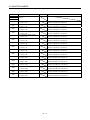
A - 14
6.23.1 Summary ......................................................................................................................................... 6-60
6.23.2 Settings ............................................................................................................................................ 6-60
6.23.3 Interface ........................................................................................................................................... 6-66
6.23.4 Operation example .......................................................................................................................... 6-69
6.24 High response I/F ................................................................................................................................... 6-73
6.24.1 Summary ......................................................................................................................................... 6-73
6.24.2 Interface ........................................................................................................................................... 6-74
6.24.3 Fast start operation ......................................................................................................................... 6-75
6.24.4 Interrupt processing high speed completion .................................................................................. 6-76
6.25 In-position signal .................................................................................................................................... 6-77
6.26 Digital input/output ................................................................................................................................. 6-78
6.26.1 Summary ......................................................................................................................................... 6-78
6.26.2 Interface ........................................................................................................................................... 6-79
6.27 Servo amplifier general input/output ...................................................................................................... 6-80
6.27.1 Summary ......................................................................................................................................... 6-80
6.27.2 Settings ............................................................................................................................................ 6-82
6.28 Dual port memory exclusive control ...................................................................................................... 6-84
6.28.1 Summary ......................................................................................................................................... 6-84
6.28.2 Exclusive control of digital output ................................................................................................... 6-84
6.29 Pass position interrupt............................................................................................................................ 6-86
6.29.1 Summary ......................................................................................................................................... 6-86
6.29.2 Pass position interrupt setting method ........................................................................................... 6-87
6.29.3 Interface ........................................................................................................................................... 6-88
6.29.4 Operation example .......................................................................................................................... 6-99
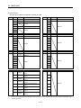
7. AUXILIARY FUNCTION
7- 1 to 7-104
7.1 Reading/writing parameters ...................................................................................................................... 7- 1
7.1.1 Writing parameters ............................................................................................................................. 7- 1
7.1.2 Reading parameters ........................................................................................................................... 7- 3
7.2 Changing parameters at the servo ........................................................................................................... 7- 4
7.3 Alarm and system error............................................................................................................................. 7- 6
7.4 Monitor function ......................................................................................................................................... 7- 8
7.4.1 Summary ............................................................................................................................................ 7- 8
7.4.2 Monitor latch function ........................................................................................................................ 7-10
7.5 High speed monitor function .................................................................................................................... 7-11
7.5.1 Summary ........................................................................................................................................... 7-11
7.5.2 Monitor latch function ........................................................................................................................ 7-12
7.6 Interrupt .................................................................................................................................................... 7-13
7.6.1 Interrupt sequence ............................................................................................................................ 7-13
7.6.2 Interrupt conditions ............................................................................................................................ 7-15
7.6.3 Factor of interrupt .............................................................................................................................. 7-16
7.6.4 Interrupt processing example............................................................................................................ 7-24
7.7 User watchdog function ........................................................................................................................... 7-25
7.8 Software reboot function .......................................................................................................................... 7-26
7.9 Parameter backup .................................................................................................................................... 7-27
7.10 Test mode............................................................................................................................................... 7-31
7.10.1 Structural diagram ........................................................................................................................... 7-31
7.10.2 Test operation mode ....................................................................................................................... 7-32
7.11 Reconnect/disconnect function.............................................................................................................. 7-33
A - 15
7.11.1 Disconnection function summary.................................................................................................... 7-33
7.11.2 Reconnect function summary ......................................................................................................... 7-34
7.11.3 Interface ........................................................................................................................................... 7-35
7.11.4 Disconnection method..................................................................................................................... 7-36
7.11.5 Reconnection method ..................................................................................................................... 7-37
7.11.6 Restrictions ...................................................................................................................................... 7-38
7.12 Sampling................................................................................................................................................. 7-39
7.12.1 Summary ......................................................................................................................................... 7-39
7.12.2 Command/status bit ........................................................................................................................ 7-40
7.12.3 Command/status data ..................................................................................................................... 7-43
7.12.4 Sampling setting write/read............................................................................................................. 7-46
7.12.5 Details for sampling function settings ............................................................................................. 7-47
7.12.6 Number of sampled points .............................................................................................................. 7-53
7.12.7 Sampling items ................................................................................................................................ 7-54
7.12.8 Sampling trigger .............................................................................................................................. 7-60
7.12.9 Sampling data read ......................................................................................................................... 7-63
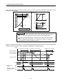
7.12.10 Timing chart for sampling function................................................................................................ 7-65
7.13 Log .......................................................................................................................................................... 7-74
7.13.1 Summary ......................................................................................................................................... 7-74
7.13.2 Log data details ............................................................................................................................... 7-75
7.13.3 Event code list ................................................................................................................................. 7-76
7.13.4 Information for each event .............................................................................................................. 7-77
7.13.5 Log function interface ...................................................................................................................... 7-85
7.13.6 Timing chart for reading of log data ................................................................................................ 7-88
7.13.7 Log acquiring selection ................................................................................................................... 7-88
7.14 Operation cycle monitor function ........................................................................................................... 7-89
7.14.1 Summary ......................................................................................................................................... 7-89
7.14.2 Interface ........................................................................................................................................... 7-89
7.14.3 Operation timing .............................................................................................................................. 7-90
7.15 Amplifier-less axis function .................................................................................................................... 7-91
7.15.1 Summary ......................................................................................................................................... 7-91
7.15.2 Interface ........................................................................................................................................... 7-91
7.15.3 Control details .................................................................................................................................. 7-92
7.16 Alarm history function............................................................................................................................. 7-93
7.16.1 Summary ......................................................................................................................................... 7-93
7.16.2 Alarm history data details ................................................................................................................ 7-94
7.16.3 Interface ........................................................................................................................................... 7-99
7.16.4 Timing chart for alarm history read ............................................................................................... 7-102
7.16.5 Alarm history initialization procedure ............................................................................................ 7-103
7.16.6 List of system errors that do not apply to alarm history storage .................................................. 7-104
8. TANDEM DRIVE
8- 1 to 8-34
8.1 Drive modes .............................................................................................................................................. 8- 1
8.1.1 Synchronous mode ............................................................................................................................ 8- 2
8.1.2 Non-synchronous micro-adjustment control mode ........................................................................... 8- 2
8.1.3 Changing of drive mode ..................................................................................................................... 8- 3
8.2 Parameter settings .................................................................................................................................... 8- 4
8.2.1 Designation of tandem drive axes ..................................................................................................... 8- 4
8.2.2 Servo parameters ............................................................................................................................... 8- 4
A - 16
8.2.3 Control parameters............................................................................................................................. 8- 4
8.3 Axis data classifications ............................................................................................................................ 8- 5
8.3.1 Only data from master axis is valid .................................................................................................... 8- 5
8.3.2 Individual data for master axis/slave axis .......................................................................................... 8- 5
8.4 Tandem drive axis operation .................................................................................................................... 8- 6
8.4.1 Home position return during tandem drive ........................................................................................ 8- 6
8.4.2 JOG operation during tandem drive ................................................................................................. 8-25
8.4.3 Incremental feed while using tandem drive ...................................................................................... 8-26
8.4.4 Automatic operation during tandem drive......................................................................................... 8-27
8.4.5 Linear interpolation during tandem drive .......................................................................................... 8-28
8.5 Servo on and servo off during tandem drive axis operation ................................................................... 8-30
8.6 Tandem drive axis limit switch ................................................................................................................. 8-31
8.7 Tandem drive axis software limit ............................................................................................................. 8-32
8.8 Tandem drive interference check ............................................................................................................ 8-32
8.9 Tandem drive axis servo alarms.............................................................................................................. 8-33
8.10 Deviation monitoring function ................................................................................................................ 8-33
9. INTERFACE MODE
9- 1 to 9-24
9.1 Summary ................................................................................................................................................... 9- 1
9.2 Combinations with functions ..................................................................................................................... 9- 2
9.3 Parameters ................................................................................................................................................ 9- 4
9.4 Interface ..................................................................................................................................................... 9- 6
9.5 Control method .......................................................................................................................................... 9- 9
9.5.1 Control method for interrupt output invalid ........................................................................................ 9- 9
9.5.2 Control method for interrupt output valid .......................................................................................... 9-11
9.6 Interrupt output cycle................................................................................................................................ 9-15
9.7 Command data update cycle ................................................................................................................... 9-16
9.8 Servo off ................................................................................................................................................... 9-17
9.9 Home position return ................................................................................................................................ 9-18
9.10 Coordinate management ....................................................................................................................... 9-20
9.10.1 Incremental system ......................................................................................................................... 9-20
9.10.2 Absolute position system ................................................................................................................ 9-22
10. TABLE MAP
10- 1 to 10-46
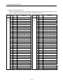
10.1 Table list ................................................................................................................................................ 10- 1
10.2 System information ............................................................................................................................... 10- 2
10.3 System command/status table ............................................................................................................. 10- 4
10.4 Factor of interrupt ................................................................................................................................. 10-16
10.5 System configuration information table ............................................................................................... 10-24
10.6 Axis data ............................................................................................................................................... 10-25
10.6.1 Axis data command table.............................................................................................................. 10-25
10.6.2 Axis data status table .................................................................................................................... 10-32
10.7 Servo parameter change number........................................................................................................ 10-40
10.8 Point number offset .............................................................................................................................. 10-44
10.9 Position command buffer ..................................................................................................................... 10-45
10.10 Digital input/output table .................................................................................................................... 10-46
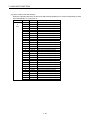
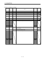
11. PARAMETERS
11- 1 to 11-34
11.1 System parameters ............................................................................................................................... 11- 2
A - 17
11.2 Servo parameters .................................................................................................................................. 11- 4
11.2.1 Servo amplifier MR-J4(W )- B .................................................................................................... 11- 4
11.3 Control parameters .............................................................................................................................. 11-22
12. MONITOR NUMBER
12- 1 to 12-20
12.1 Servo information (1)............................................................................................................................. 12- 1
12.2 Servo information (2)............................................................................................................................. 12- 3
12.3 Operation information ........................................................................................................................... 12- 8
12.4 Operation information (double word) ................................................................................................... 12-11
12.5 System information .............................................................................................................................. 12-12
12.6 Servo parameter information ............................................................................................................... 12-14
13. ALARM NUMBER
13- 1 to 13-10
13.1 System alarm ........................................................................................................................................ 13- 1
13.2 Servo alarm ........................................................................................................................................... 13- 2
13.3 Operation alarm..................................................................................................................................... 13- 4
13.4 System error .......................................................................................................................................... 13- 9
14. EMC AND LOW VOLTAGE DIRECTIVES
14- 1 to 14- 6
14.1 Requirements for compliance with the EMC directive ......................................................................... 14- 1
14.1.1 Standards relevant to the EMC directive ....................................................................................... 14- 2
14.1.2 Installation instructions for EMC directive ..................................................................................... 14- 3
14.1.3 Parts of measure against noise ..................................................................................................... 14- 5
14.2 Requirements for compliance with the low voltage directive ............................................................... 14- 6
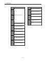
APPENDIX
App.- 1 to App.-78
App. 1 Supplementary explanation for the use of linear servo system ................................................... App.- 1
App. 1.1 Position board ......................................................................................................................... App.- 1
App. 1.2 Position board utility software ................................................................................................. App.- 1
App. 1.3 Servo amplifier ........................................................................................................................ App.- 1
App. 1.4 Operations and functions of the linear servo system ............................................................ App.- 2
App. 2 Supplementary explanation for the use of fully closed loop system ........................................... App.-13
App. 2.1 Position board ........................................................................................................................ App.-13
App. 2.2 Position board utility software ................................................................................................ App.-13
App. 2.3 Servo amplifier ....................................................................................................................... App.-13
App. 2.4 Operations and functions of the fully closed loop control ..................................................... App.-14
App. 3 Supplementary explanation for the use of direct drive servo system ......................................... App.-21
App. 3.1 Position board ....................................................................................................................... App.- 21
App. 3.2 Position board utility software ............................................................................................... App.- 21
App. 3.3 Servo amplifier ...................................................................................................................... App.- 21
App. 3.4 Operations and functions of the direct drive servo system .................................................. App.-22
App. 4 Supplementary explanation for the use of multiple-axis servo amplifier (MR-J4W - B) ....... App.-28
App. 4.1 Position board ........................................................................................................................ App.-28
App. 4.2 Position board utility software ................................................................................................ App.-28
App. 4.3 Servo amplifier ....................................................................................................................... App.-28
App. 4.4 Operations and functions of the servo amplifier ................................................................... App.-28
A - 18
App. 5 Supplementary explanation for the use of SSCNET compatible servo amplifier
(MR-J3(W)- B) ........................................................................................................................... App.-30
App. 5.1 Position board ........................................................................................................................ App.-30
App. 5.2 Position board utility software ................................................................................................ App.-30
App. 5.3 Connectable units .................................................................................................................. App.-30
App. 5.4 System setting ....................................................................................................................... App.-31
App. 5.5 System configuration ............................................................................................................. App.-31
App. 5.5.1 System configuration diagram ....................................................................................... App.-31
App. 5.6 Axis No. setting ...................................................................................................................... App.-32
App. 5.6.1 Servo amplifier setting.................................................................................................... App.-32
App. 5.7 Parameter setting .................................................................................................................. App.-33
App. 5.7.1 System option 1 setting .................................................................................................. App.-33
App. 5.8 Control option 1 setting .......................................................................................................... App.-35
App. 5.9 Axis No. assignment .............................................................................................................. App.-36
App. 5.10 Sensor input option setting .................................................................................................. App.-38
App. 5.11 Vendor ID and type code setting ......................................................................................... App.-41
App. 5.12 System startup processing .................................................................................................. App.-41
App. 5.13 Restrictions when using J3 compatibility mode .................................................................. App.-42
App. 5.14 Supported functions ............................................................................................................. App.-44
App. 5.14.1 Application functions .................................................................................................... App.-46
App. 5.14.2 Auxiliary function .......................................................................................................... App.-50
App. 5.15 Table map ............................................................................................................................ App.-51
App. 5.15.1 Table list ....................................................................................................................... App.-51
App. 5.15.2 System information ...................................................................................................... App.-52
App. 5.15.3 Servo parameter change number................................................................................ App.-53
App. 5.16 Parameters .......................................................................................................................... App.-54
App. 5.16.1 System parameters ...................................................................................................... App.-54
App. 5.16.2 Servo parameters......................................................................................................... App.-55
App. 5.16.3 Control parameters ...................................................................................................... App.-62
App. 5.17 Monitor ................................................................................................................................. App.-63
App. 5.17.1 Servo information (1).................................................................................................... App.-63
App. 5.17.2 Servo information (2).................................................................................................... App.-65
App. 5.17.3 Servo parameter information ....................................................................................... App.-70
App. 5.18 System alarm ....................................................................................................................... App.-72
App. 5.18.1 Servo alarm .................................................................................................................. App.-72
App. 6 Cables ........................................................................................................................................... App.-73
App. 6.1 SSCNET cables .................................................................................................................. App.-73
App. 6.2 Forced stop input cable ......................................................................................................... App.-76
App. 6.3 SSCNET cables (SC-J3BUS M-C) manufactured by Mitsubishi Electric System &
Service.................................................................................................................................... App.-77
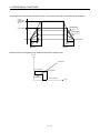
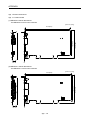
App. 7 Exterior dimensions ...................................................................................................................... App.-78
App. 7.1 Position board ........................................................................................................................ App.-78
A - 19
About Manuals
The following manuals are also related to this product.
In necessary, order them by quoting the details in the tables below.
Related Manuals
(1) Position Board
Manual Number
(Model Code)
Manual Name
MR-MC210/MR-MC211 Position Board User's Manual (Details)
This manual explains specifications of the position board, information on how to establish a system,
maintenance/inspection, trouble shooting, functions for the positioning control of the position board,
IB-0300223
(1XB968)
programming, dual port memory and others.
MR-MC210/MR-MC211 Position Board User's Manual (API Library)
This manual explains the library of functions and others that the host controller uses to control the position
board.
A - 20
IB-0300225
(1XB970)
(2) Servo amplifier
Manual Number
(Model Code)
Manual Name
SSCNET /H interface MR-J4- B Servo amplifier Instruction Manual
This manual explains the I/O signals, parts names, parameters, start-up procedure and others for
SH-030106
(1CW805)
MR-J4- B Servo amplifier.
SSCNET /H interface Multi-axis AC Servo MR-J4W- B Servo amplifier Instruction Manual
This manual explains the I/O signals, parts names, parameters, start-up procedure and others for Multi-
SH-030105
(1CW806)
axis AC Servo MR-J4W - B Servo amplifier.
SSCNET
interface MR-J3- B Servo amplifier Instruction Manual
This manual explains the I/O signals, parts names, parameters, start-up procedure and others for
SH-030051
(1CW202)
MR-J3- B Servo amplifier.
SSCNET
Manual
interface 2-axis AC Servo Amplifier MR-J3W- B Servo amplifier Instruction
This manual explains the I/O signals, parts names, parameters, start-up procedure and others for 2-axis
AC Servo Amplifier MR-J3W- B Servo amplifier.
SSCNET
Compatible Linear Servo MR-J3- B-RJ004 Instruction Manual
This manual explains the I/O signals, parts names, parameters, start-up procedure and others for Linear
SH-030073
(1CW604)
SH-030054
(1CW943)
Servo MR-J3- B-RJ004 Servo amplifier.
SSCNET Compatible Fully Closed Loop Control MR-J3- B-RJ006 Servo amplifier
Instruction Manual
This manual explains the I/O signals, parts names, parameters, start-up procedure and others for Fully
SH-030056
(1CW304)
Closed Loop Control MR-J3- B-RJ006 Servo amplifier.
SSCNET
Manual
Interface Direct Drive Servo MR-J3- B-RJ080W Servo amplifier Instruction
This manual explains the I/O signals, parts names, parameters, start-up procedure and others for Direct
SH-030079
(1CW601)
Drive Servo MR-J3- B-RJ080W Servo amplifier.
SSCNET
Manual
interface Drive Safety integrated MR-J3- B Safety Servo amplifier Instruction
This manual explains the I/O signals, parts names, parameters, start-up procedure and others for safety
integrated MR-J3- B Safety Servo amplifier.
A - 21
SH-030084
(1CW205)
MEMO
A - 22
1. SUMMARY
1. SUMMARY
1
1.1 Summary
This manual describes the specifications and handling of SSCNET /H compatible position board
(MR-MC210/MR-MC211).
In this manual, the following abbreviations are used.
Generic term/Abbreviation
Description
MR-MC21
General name for position board MR-MC210/MR-MC211.
Host controller
General name for computer equipped with position board and operates user
program.
MR-J4(W )- B
Servo amplifier model MR-J4- B/MR-J4W - B
MR-J3(W)- B
Servo amplifier model MR-J3- B/MR-J3W- B
Servo amplifier
General name for SSCNET /H compatible servo amplifier.
Utility software
General name for the Position Board Utility2 (MRZJW3-MC2-UTL) which
includes test tool for start-up and examination, and the API library for position
board.
Test tool
Abbreviation for start-up and examination tool for position board.
API library
General name for the library of functions for positioning control that the host
controller uses to control the position board.
MR Configurator2
Abbreviation for the Servo set-up software MR Configurator2 version 1.10L or
later.
User program
Program created by the user that operates on the host controller.
System program
Internal program that controls the position board.
SSCNET /H(Note)
High-speed synchronized network between the position board and the servo
amplifier.
SSCNET (Note)
SSCNET (/H)(Note)
General name for SSCNET /H, SSCNET .
Board Ver.
System version of position board.
API Ver.
Software version of the API library for position board.
Note. SSCNET: Servo System Controller NETwork
1-1
1. SUMMARY
(1) PCI bus compatible position board
The PCI bus compatible position board (MR-MC210/MR-MC211) is a board compatible with PCI bus
mounted to the host controller and controls our servo amplifiers (MR-J4(W )- B/MR-J3(W)- B). The PCI
bus compatible position board and the servo amplifiers are connected with SSCNET /H, which is a high
speed synchronous network.
Servo amplifier (MR-J4(W )- B)
Host controller
Position
instructions
parameters
Position
board
Position
feedback
Speed
feedback
For the PCI bus compatible position board, there are two types, MR-MC210 and MR-MC211.
The MR-MC210 has one SSCNET control channel (hereinafter: CH) and one SSCNET communication
system (hereinafter: communication system), and can control positioning for up to 20 axes. The MR-MC211
has one SSCNET control channel and two SSCNET communication systems, and can control positioning
for up to 32 axes (up to 20 axes per system). By reading and writing the dual port memory mapped to the
memory space of the PCI bus, the host controller can command position board to start operation, and get
servo amplifier status. The host controller can also receive position pass and positioning complete
interruptions via PCI bus.
The position board is equipped with standard mode and interface mode for positioning control. The
positioning control mode that corresponds with the application can be selected by parameter. The mode
cannot be changed during SSCNET communication (during system startup). Positioning in standard mode
is performed using a point table mapped on the dual port memory of the position board. Arbitrary
positioning is possible by writing data to this point table from the host controller.
Also, startup of JOG operation and home position return, etc. as well as parameters changing and
monitoring are possible through accessing this dual port memory on the position board from the host
controller.
Interface mode is a sequential positioning command method that uses a user program on the host
controller. The user program controls the servo amplifier with an arbitrary acceleration/deceleration pattern
by writing the position command to the position command buffer of the position board every communication
cycle (control cycle). Some functions from standard mode cannot be used, or are restricted when in
interface mode.
1-2
1. SUMMARY
Bus
interface
Dual port
memory
CPU
SSCNET
Communication IC
SSCNET /H
LOCAL BUS
(Max 20 axes)
SSCNET
Communication IC
SSCNET /H
(Max 12 axes)
PCI BUS
Inside the dotted line: only when using MR-MC211
1-3
1. SUMMARY
1.2 Features of MR-MC21
The position board MR-MC21
has the following features.
(1) Structuring of SSCNET /H communication servo system by computer control
The position board can be directly connected to the Mitsubishi servo amplifiers of MR-J4-B series using
SSCNET /H.
(a) By connecting the position board and servo amplifier and servo amplifiers with a high speed
synchronous network by SSCNET /H, the reduction of wiring is achieved. The maximum distance
between the position board and servo amplifier, or servo amplifier and servo amplifier for the SSCNET
cable on the same bus is 100(328.08)[m(ft.)]. This increases flexibility at system design.
(b) By using SSCNET cable (optical communication), the influence of electromagnetic noise etc. from
servo amplifiers and such is reduced.
(c) The servo parameters can be set on the position board side and written to the servo amplifier, or read
from the servo amplifier using the SSCNET communication.
(d) The current feedback position and error description contained in the servo can be checked by the dual
port memory of the position board.
(e) Communication between MR Configurator2 and the servo amplifiers is possible via the position board
USB.
(2) Programming in C programming language with the API library
Positioning control for the servo in C programming language is enabled with the API library included with
the Position Board Utility2 (MRZJW3-MC2-UTL).
(3) Supports event-driven programming
The host controller is notified by interrupt via PCI bus when the conditions for an interrupt such as passing
through a preset point or positioning complete are met. The user program can create event-driven
programs according to interrupt factors.
(4) High-speed operation starting time
High-speed operation starting time within the control cycle (0.22ms fastest) is achieved for the maximum
number of synchronous startup axes or less.
1-4
1. SUMMARY
(5) Wide variety of positioning control functions
The main functions (such as home position return control, standard mode, and interface mode (sequential
positioning command method)) which are required for any positioning system and the sub functions which
limit and add functions to those controls are supported.
(a) Enhanced home position return control
Additional features of home position return control
Ten home position return methods are provided: dog cradle method, dog method, data set method,
continuous operation to torque method, limit switch combined method, scale home position signal
detection method, limit switch front end method, dog front end method, Z-phase detection method, and
scale home position signal detection method 2. Select an applicable method according to the system.
(b) Wide variety of control methods
Positioning control methods such as positioning control are provided.
1) Independent control of each axis
Position control can be performed independently for each axis at any given timing.
2) Interpolation control
Interpolation controls using multiple axes can be performed.
(2-axis to 4-axis linear interpolation control)
3) Tandem drive
Tandem drive for 2 axes can be performed. In scale home position signal detection method and scale
home position signal detection method 2, the deviation between the 2 axes at home position return
can be compensated.
4) Interface mode
The user program controls the servo amplifier with an arbitrary acceleration/deceleration pattern that
is not supported in standard mode by writing the position command to the position command buffer of
the position board every communication cycle (control cycle).
(c) Continuous processing of multiple positioning data
Multiple positioning data can be processed continuously within one operation start.
(d) Acceleration/deceleration processing
Four acceleration/deceleration processing methods are provided: Linear acceleration/deceleration,
S-curve acceleration/deceleration, start up speed, and smoothing filter.
The acceleration/deceleration curve can be selected according to the machine characteristic.
(6) Supports other axes start function
With the other axes start function, the position board can determine the conditions and automatically start
other axes, and turn on/off output signals. The position board does not go through user program processing
so there are no delays or dispersions. This also lessens the load on the user program.
(7) High maintainability
Maintainability is enhanced in the position board.
(a) Data retention without battery
Parameter data can be stored in the flash ROM inside the position board. This feature allows the
retaining of data without a battery.
(b) Alarm collection function
The alarm details when an alarm occurs are automatically stored in the flash ROM inside the position
board.
Storing the alarm information allows the user to check the alarm from the user program or test tool even
after the position board is powered off or reset.
1-5
1. SUMMARY
(8) Setting, monitoring, and testing through test tool
Using the test tool of Position Board Utility2 (MRZJW3-MC2-UTL), users can check the validity of the preset
parameters and point table by performing test operation of the position board before creating a user
program.
The control monitor/graph function allows users to debug programs efficiently.
(9) Forced stop function
The batch forced stop is available for connected servo amplifiers by the forced stop input signal of the
external input.
(10) Easy application to the absolute position system
(a) The MR-J4(W )- B series servo amplifiers and servo motors support the absolute position system.
Absolute position system can be used by connecting the battery for absolute position system to the
servo amplifier.
(b) Once the home position has been established, the home position return operation is unnecessary at the
system's power supply ON.
(c) With the absolute position system, the data set method home position return is used to establish the
home position. The wiring of proximity dog, etc. is unnecessary.
1-6
1. SUMMARY
1.3 Specifications
1.3.1 General specifications
General specifications of the position board are shown below.
Items
Specification
Operating ambient temperature
0 to 55°C (32 to 131°F)
Storage ambient temperature
Operating ambient humidity
Storage ambient humidity
Operating ambience
-20 to 65°C (4 to 149°F)
10 to 90% RH, non-condensing
10 to 90% RH, non-condensing
Indoors (where not subject to direct sunlight), no corrosive gas, no significant amount of dirt or dust
Cooling method
Power supply
Self cooling
MR-MC210 Power supply voltage: 5VDC ± 5%; Leakage current: less than 450mA
MR-MC211 Power supply voltage: 5VDC ± 5%; Leakage current: less than 700mA
CAUTION
The position board must be stored and used under the conditions listed in the table of
specifications above.
When not using for a long time, disconnect the power line from the servo amplifier.
Place the position board and servo amplifier in static electricity preventing vinyl bags and store.
When storing for a long time, please contact with our sales representative.
Also, execute a trial operation.
1-7
1. SUMMARY
1.3.2 List of specifications of position board
(1) Position board control specifications
Function
System function
Control cycle
Control axes
Max 20
Control mode
Standard mode: Position controlling method by
position board
Interface mode : Sequential positioning command
method by user program
SSCNET /H, SSCNET
SSCNET communication
Operation function JOG operation
(Note 1, 2)
Incremental feed
Provided
Provided
Point table method, 1 axis control
Linear interpolation
Point table method, MAX 4 axes interpolation is
available
Dog cradle method, Dog method, Data set method,
Stopper method, Limit switch combined method,
Scale home position signal detection method,
Limit switch front end method, Dog front end method,
Z-phase detection method,
Scale home position signal detection method 2
Home position reset (data set)
Electronic gear
Stop function
Limit switch
Provided (Hardware stroke limit)
Software limit
Provided (Software stroke limit)
Interlock
Provided
Acceleration/deceleration
Unavailable when the
control cycle is 0.22ms
Can indicate direction for
home position return
Proximity dog is for level
detection
The current position can
be reset to the home
position
Electronic gear numerator
Electronic gear denominator
: 1 to 5242879
: 1 to 589823
Command unit/min, command unit/s, and r/min can
be selected.
Command speed limits: 1 to speed limit
Limits of start speed: 1 to speed limit
Time constant limits: 0 to 20000 ms/speed limit
Separate setting of constants for deceleration and
acceleration: provided
Setting of constants for separate points: provided
Acceleration/deceleration method:
Linear acceleration/deceleration,
smoothing filter, start up speed,
S-curve acceleration/deceleration
(sine acceleration/deceleration)
Forced stop, Stop operation, Rapid stop operation
Speed units
Remarks
Max 32
Automatic operation
Home position return
Application
function
Contents
MR-MC210
MR-MC211
0.88ms/0.44ms/0.22ms(Select using parameters.)
Rough match output
Provided
Torque limit
Provided
Note 1. The position board can move within the limits of 2147483648 to 2147483647. Movement outside the limits is not covered with
warranty. If software limits have been disabled, be careful not to move it outside of the physical limits.
2. For the absolute position detection system, the command limits of the position after calculation using the electronic gear are
also 2147483648 to 2147483647. It is possible for the moveable limits to be narrower than 2147483648 to 2147483647,
depending on the electronic gear.
1-8
1. SUMMARY
Function
Application
function
Help function
Command change
Backlash
Provided
Position switch
Provided
Interference check
Provided
Provided
Provided
PI-PID switching
Provided
Absolute position detection
system
Home position return request
Provided
Provided
Other axes start
Provided
Digital input/output
Provided
Servo amplifier general
input/output
Dual port memory exclusive
control
Pass position interrupt
Provided
Provided
Tandem drive
Provided
Monitor
Current command position,
Current feedback position, Speed command,
Position droop, Electrical current command,
Servo alarm number, External signal status, etc.
Current command position,
Current feedback position, Moving speed,
Feedback moving speed, External signal,
Electrical current feedback
During start operation, Operation stoppage
(During operation, in-position, during smoothing of
stopping, rough match, etc.)
When alarm goes off (servo alarm/operation alarm),
etc.
Provided (Check for the watchdog of the of the user
program)
Parameters can be saved to the flash ROM.
User watchdog
Parameter backup
Test mode
Reconnect/disconnect
Sampling
Log
Alarm history
Board ID
Remarks
Unavailable when the
control cycle is 0.22ms
Gain switching
Interrupt
DO
MR-MC211
Home position search limit
High speed monitor
DI
Contents
MR-MC210
Location, speed, time constant
Provided
Can be latched
Updated per control cycle
Can be latched
Interrupt generation
conditions can be
selected.
Processed by
software.(Note 3)
By connecting MR Configurator2 via the position
board, the servo amplifier can be simply tested.
Provided
The maximum sampling point: 65536.
(Ring buffer of 8192 points)
History of start operation, alarms, etc, can be
recorded.
Alarm history is saved to the flash ROM.
0 to 3
Select using DIP-SW
Limit switch
None
Limit switch
None
Proximity dog
None
DI signals are input from
the servo amplifier or the
dual port memory, etc. by
the parameter setting.
Forced stop
1 point
None
Note 3. This is not the watch dog for the CPU on the position board.
1-9
1. SUMMARY
1.4 Name of each section
(1) Name of parts for MR-MC210
2) 3)
4)
5)
1)
6)
SW1
1 - 10
1. SUMMARY
No.
1)
Item
Function
Setting switch (SW1)
<Board ID selection>
Define a board ID in order to distinguish between multiple position
boards.
Switch 2
Switch 1
Board ID
ON
ON
3
ON
OFF
2
OFF
ON
1
OFF
OFF
0
(default value)
ON
<For manufacturer setting>
This switch is provided for manufacturer setting.
Make sure the switch is always OFF.
1 2 3 4
Switch 3
For manufacturer setting
OFF
<Interrupt output mask selection>
Masks interrupt output when interrupt occurs.
Switch 4
Interrupt output mask
ON
Valid
OFF
Invalid
(default value)
2)
Operation indicator (green)
At power ON: ON, At system startup: Flicker, At power OFF: OFF
3)
Error indicator (red)
Normal: OFF, At system error (E001 to E302) occurrence: ON
4)
USB connector
A communication connector to connect with the position board test tool, MR Configurator2.
(connects MR-J3USBCBL3M)
5)
SSCNET connector
Connector for communication with a servo amplifier. (connects MR-J3BUS M)
(communication system 1) (Note 1)
6)
Forced stop input connector
(Note 2)
The following is the pin layout and connections of the forced stop input connector as viewed
from the front.
Pin No.
123
Signal name
1
EMI
2
No connect
3
EMI.COM
Note. Do not connect to any of the terminals explained as "No connect".
<Cable-side connector model name>
Manufacturer
Molex
Name
Model
Crimp
housing
Reference
51103-0300
Crimp
terminal
50351-8100
Applicable wire size (AWG): 22, 24, 26, 28
Two crimp terminals are required per housing.
Hand crimp
tool
63811-8100
Applicable terminal: 50351
Note 1. Put the SSCNET cable in the duct or fix the cable at the closest part to the position board with bundle material in order to prevent
SSCNET cable from putting it's own weight on SSCNET connector.
2. Be sure to use the cable for forced stop input. The forced stop cannot be released without using it. Make the cable length within
30m(98.43ft).
1 - 11
1. SUMMARY
(2) Name of parts for MR-MC211
2) 3)
4)
5)
6)
1)
7)
SW1
1 - 12
1. SUMMARY
No.
1)
Item
Function
Setting switch (SW1)
<Board ID selection>
Define a board ID in order to distinguish between multiple position
boards.
Switch 2
Switch 1
Board ID
ON
ON
3
ON
OFF
2
OFF
ON
1
OFF
OFF
0
(default value)
ON
<For manufacturer setting>
This switch is provided for manufacturer setting.
Make sure the switch is always OFF.
1 2 3 4
Switch 3
For manufacturer setting
OFF
<Interrupt output mask selection>
Masks interrupt output when interrupt occurs.
Switch 4
Interrupt output mask
ON
Valid
OFF
Invalid
(default value)
2)
Operation indicator (green)
At power ON: ON, At system startup: Flicker, At power OFF: OFF
3)
Error indicator (red)
Normal: OFF, At system error (E001 to E302) occurrence: ON
4)
USB connector
A communication connector to connect with the position board test tool, MR Configurator2.
(connects MR-J3USBCBL3M)
5)
SSCNET connector
Connector for communication with a servo amplifier. (connects MR-J3BUS M)
(communication system 1) (Note 1)
6)
SSCNET connector
(communication system 2) (Note 1)
7)
Forced stop input connector
(Note 2)
The following is the pin layout and connections of the forced stop input connector as viewed
from the front.
Pin No.
123
Signal name
1
EMI
2
No connect
3
EMI.COM
Note. Do not connect to any of the terminals explained as "No connect".
<Cable-side connector model name>
Manufacturer
Molex
Name
Model
Crimp
housing
Reference
51103-0300
Crimp
terminal
50351-8100
Applicable wire size (AWG): 22, 24, 26, 28
Two crimp terminals are required per housing.
Hand crimp
tool
63811-8100
Applicable terminal: 50351
Note 1. Put the SSCNET cable in the duct or fix the cable at the closest part to the position board with bundle material in order to prevent
SSCNET cable from putting it's own weight on SSCNET connector.
2. Be sure to use the cable for forced stop input. The forced stop cannot be released without using it. Make the cable length within
30m(98.43ft).
1 - 13
1. SUMMARY
1.5 Bus interface
1.5.1 Configuration register
The following shows the configuration register of PCI bus compatible position board (MR-MC210/MR-MC211).
Address
31 to 24
23 to16
15 to 8
00
Device ID
0624
Vendor ID
10BA
04
Status
Command
08
Class Code
118000
0C
BIST
(Note)
10
Base Address Register 0
14
Base Address Register 1
18
7 to 0
Revision ID
01
Header Type
(Note)
Latency Timer
(Note)
Base Address Register 3 (Note)
20
Base Address Register 4 (Note)
24
Base Address Register 5 (Note)
28
Cardbus CIS Pointer (Note)
2C
Subsystem ID
0601
Revision ID: 01
Class Code: 118000 (data processing controller)
Cache Line Size
(Note)
Dual port memory (including board ID) leading
address
Memory Space Indicator (bit0):
0 (Memory space)
Type (bit1 to 2):
00 (32 bits, arbitrary position of address space)
Prefetchable (bit3):
0 (Prefetch prohibited)
Base Address Register 2
1C
Remarks
Vender ID: Mitsubishi Electric 10BA
Device ID: 0624
Subsystem Vendor ID
10BA
30
Expansion ROM Base Address (Note)
34
(Reserved) (Note)
38
(Reserved) (Note)
3C
Max_Lat (Note)
Subsystem Vender ID: Mitsubishi Electric 10BA
Subsystem ID: 0601
CAP_PTR (Note)
Min_Gnt (Note)
Interrupt Pin 01
Interrupt Line
Interrupt Pin: 01(INTA use)
Note. Has not been implemented, therefore, if read an indefinite value will be returned.
1 - 14
1. SUMMARY
1.5.2 Dual port memory map
The bus width of dual port memory is 32 bits. For the address map of the dual port memory on the position
board side, refer to Chapter 10.
(1) MR-MC210/MR-MC211
PCI bus
Offset address
+000000h
Memory space of 1CH
+00FFFFh
+010000h
Reserved
+01FFFFh
+020000h
Module information
+02000Fh
1 - 15
1. SUMMARY
1.5.3 Module information
(1) MR-MC210/MR-MC211
The (R)s in the table designate read only, while the (W)s designate write only capability.
Address
bit7
020000
bit6
Bus type (R)
bit5
bit4
Implemented CH
information (R)
020001
bit3
bit2
Interrupt output mask
information (R)
Reserved
Reserved
020002
bit1
bit0
Board ID information (R)
Number of SSCNET
communication systems
(R)
Reserved
020003
020004
Reserved
Signal during interrupt
output (R)
020005
020006
Reserved
020007
020008
Reserved
020009
Reserved
02000A
02000B
02000C
Reserved
02000D
02000E
Reserved
02000F
(a) Board ID information (address 020000h)
Status set with the dip switch is displayed.
bit1
bit0
Content
0
0
0
0
1
1
1
0
2
1
1
3
(b) Interrupt output mask information (address 020000h)
Status set with the dip switch is displayed.
bit3
Content
0
Invalid
1
Valid
(c) Implemented CH information (address 020000h)
bit5
bit4
0
0
Content
1CH
0
1
Reserved
1
0
Reserved
1
1
Reserved
1 - 16
Interrupt signal clear
register (1CH) (W)
1. SUMMARY
(d) Bus type (address 020000h)
bit7
bit6
Content
0
0
PCI bus
0
1
Reserved
1
0
Reserved
1
1
Reserved
(e) Number of SSCNET communication systems (address 020001h)
bit7
bit6
Content
0
0
1 communication system
0
1
2 communication system
1
0
Reserved
1
1
Reserved
(f) Signal during interrupt output (address 020004h)
bit1
bit0
Content
0
0
Interrupts are not generated
0
1
During interrupt output
(g) Interrupt signal clear register (1CH) (address 020008h)
bit1
bit0
0
0
Invalid
Content
0
1
1CH interrupt signal is cleared
1 - 17
1. SUMMARY
1.6 SSCNET
cables
Connect the position board and servo amplifiers, or servo amplifier and servo amplifier by SSCNET cable.
When using MR-MC210, the SSCNET cable for connecting servo amplifiers can be used for one
communication system only. When using MR-MC211, the SSCNET cable for connecting servo amplifiers can
be used for up to two communication systems (use 1CH and 2CH). Up to 32 servo amplifiers can be
connected.
(1) SSCNET
cable specifications
Model name
MR-J3BUS M
MR-J3BUS M-A
MR-J3BUS M-B
Cable length [m(ft.)]
MR-J3BUS015M
0.15 (0.49)
MR-J3BUS03M
0.3 (0.98)
MR-J3BUS05M
0.5 (1.64)
MR-J3BUS1M
1 (3.28)
MR-J3BUS3M
3 (9.84)
MR-J3BUS5M-A
5 (16.40)
MR-J3BUS10M-A
10 (32.81)
MR-J3BUS20M-A
20 (65.62)
MR-J3BUS30M-B
30 (98.43)
MR-J3BUS40M-B
40 (131.23)
MR-J3BUS50M-B
50 (164.04)
Description
• Position board
• Servo amplifier
Servo amplifier
Servo amplifier
(2) Connection between the position board and servo amplifiers
Connect the SSCNET cables to the following connectors.
Refer to Section 3.2.1 for the connection and disconnection of SSCNET
cable.
SSCNET /H System 1
MR-MC21
1CH
1)
CN1A
2CH
(Note)
Attach a cap to
connectors of
channel not being
used.
CN1A
1)
Cap
CN1B
CN1B
Position board
Servo amplifier
(Note) MR-MC211 only
SSCNET cable length
MR-J3BUS M use
1) 3m(9.84ft.)
MR-J3BUS M-A use
1) 20m(65.62ft.)
MR-J3BUS M-B use
1) 50m(164.04ft.)
Servo amplifier
SSCNET /H System 2
1)
CN1A
CN1A
1)
CN1B
Servo amplifier
Cap
CN1B
Servo amplifier
Note. It cannot communicate if the connection of
CN1A and CN1B is mistaken.
1 - 18
1. SUMMARY
1.7 Forced stop input terminal
(1) Table of the forced stop input terminal specifications
Item
Specifications
Number of input points
Forced stop signal : 1 point
Input method
Sink/Source type
Rated input current
2.4mA
Isolation method
Photocoupler
Operating voltage range
20.4 to 26.4VDC
(+10/ -15%, ripple ratio 5% or less)
ON voltage/current
17.5VDC or more/2.0mA or more
OFF voltage/current
1.8VDC or less/0.18mA or less
Input resistance
Response time
Approx. 10k
OFF to ON
1ms or less
ON to OFF
External connector type
3 pin connector
Recommended wire size
0.08 to 0.32mm (AWG22 to AWG28)
2
(2) Forced stop circuit
(a) Sink type
Forced stop input connector
Position board side
Stabilizing power supply
+24V
24G
EMI.COM
Control
circuit
10k
EMI
Forced stop
(b) Source type
Forced stop input connector
Stabilizing power supply
+24V
EMI.COM
Position board side
Control
circuit
10k
Forced stop
EMI
24G
1 - 19
1. SUMMARY
MEMO
1 - 20
2. SYSTEM CONFIGURATION
2. SYSTEM CONFIGURATION
This section describes the system configuration and equipment settings for the position board.
2.1 MR-MC210 system configuration
SSCNET /H-compatible
Servo amplifier MR-J4-B
Axis 1
PCI bus compatible
position board
MR-MC210
USB
Axis 2
2
Axis 20
SSCNET Cable
MR-J3BUS M
MR-J3BUS M-A
MR-J3BUS M-B
SSCNET
EMI
DI signal
Forced stop (EMI
DI signal
side limit switch (LSP 1)
side limit switch (LSN 1)
Proximity dog (DOG 1)
DI signal (LSP, LSN and DOG) from Servo Amplifier
can be input
1)
2-1
2. SYSTEM CONFIGURATION
2.2 MR-MC211 system configuration
SSCNET /H-compatible
Servo amplifier MR-J4-B
PCI bus compatible
position board
MR-MC211
Axis 1
Axis 2
Axis 20
Axis 1
Axis 2
Axis 12
SSCNET Cable
MR-J3BUS M
MR-J3BUS M-A
MR-J3BUS M-B
USB
SSCNET
communication system 1
SSCNET
communication system 2
EMI
DI signal
Forced stop (EMI
1)
DI signal
side limit switch (LSP 1)
side limit switch (LSN 1)
Proximity dog (DOG 1)
DI signal (LSP, LSN and DOG) from Servo Amplifier
can be input
POINT
Refer to Section 4.5.5 to change the number of axes distributed to
communication system 1 and communication system 2
2-2
2. SYSTEM CONFIGURATION
2.3 System configuration equipment
(1) MR-MC21
related module
Model name
(Note 1)
Part name
MR-MC210
Up to 20 axes control, Operation cycle 0.22[ms], 0.44[ms], 0.88[ms]
(Note 2)
0.45
MR-MC211
Up to 32 axes control, Operation cycle 0.22[ms], 0.44[ms], 0.88[ms]
(Note 2)
0.70
MR-J3USBCBL3M
Position board MR-MC21
——
MR-J3BUS M
MR-J4(W )- B/MR-J4(W )- B
MR-J4(W )- B
• MR-MC21
• Standard cord for inside panel
0.15m(0.49ft.), 0.3m(0.98ft.), 0.5m(1.64ft.), 1m(3,28ft.), 3m(9.84ft.)
——
MR-J4(W )- B/MR-J4(W )- B
• MR-MC21
• Standard cable for outside panel
5m(16.40ft.), 10m(32.81ft.), 20m(65.62ft.)
MR-J4(W )- B
MR-J3BUS M-A
——
MR-J3BUS M-B
(Note 3)
• MR-MC21
MR-J4(W )- B/MR-J4(W )- B
• Long distance cable
30m(98.43ft.), 40m(131.23ft.), 50m(164.04ft.)
MR-J4(W )- B
Position board
USB cable
SSCNET
cable
Current
consumption Remark
5VDC[A]
Description
host controller
Note 1.
——
=Cable length (015: 0.15m(0.49ft.), 03: 0.3m(0.98ft.), 05: 0.5m(1.64ft.), 1: 1m(3.28ft.), 2: 2m(6.56ft.), 3: 3m(9.84ft.),
5: 5m(16.40ft.), 10: 10m(32.81ft.), 20: 20m(65.62ft.), 25: 25m(82.02ft.), 30: 30m(98.43ft.), 40: 40m(131.23ft.), 50: 50m(164.04ft.)
2. Be sure to use the cable for forced stop input. The forced stop cannot be released without using it.
Cable for forced stop input is not attached to the MR-MC21 . The cable should be made by the customer.
3. Please contact your nearest Mitsubishi sales representative for the cable of less than 30m(98.43ft.).
(2) Servo amplifier
Part name
MR-J4 series
servo amplifier
Model name
Description
MR-J4- B-RJ
MR-J4W- B
For 2-axis type, 3-axis type
MR-J3- B
MR-J3W- B
MR-J3 series
servo amplifier
Remarks
MR-J4- B
For 2-axis type
MR-J3- B-RJ006
For fully closed control
MR-J3- B-RJ004
For linear servo motor
MR-J3- B Safety
For drive safety servo
MR-J3W-0303BN6
For 2-axis type
Refer to the servo amplifier
instruction manuals.
(3) Software packages
(a) Utility software
Model name
Software package
Position Board Utility2
MRZJW3-MC2-UTL
(b) Servo set-up software package
Model name
Software package
MR Configurator2
SW1DNC-MRC2-E
2-3
2. SYSTEM CONFIGURATION
2.4 Checking serial number and operating system software version
Checking for the serial number of position board and software version are shown below.
2.4.1 Checking serial number
(1) Rating plate
The serial number is printed on the rating plate which is on the position board.
PASSED
5VDC 0.45A
A21001999
US LISTED
IND. CONT. EQ.
MR-MC210
UL
SERIAL
C
80M1
MADE IN JAPAN BC370C247H01
See MR-MC210 Instruction manual.
Rating
plate
KCC-REI-MEK-
TC510A815G51
2012-01
DATE:
Serial
number
POINT
When the position board is mounted to the host controller, the serial number
cannot be checked. Take note of the serial number before mounting.
2.4.2 Checking software version
The software version of the position board can be checked on the system program software version (0030h to
003Fh) of system information. System program software version is stored as ASCII code.
0030h 0031h0032h0033h 0034h 0035h 0036h 0037h 0038h 0039h003Ah003Bh003Ch003Dh003Eh003Fh
System program B
C
D
B
5
2
W
1
0
1
A
3
\0
software version (42h) (43h) (44h) (2Dh) (42h) (35h) (32h) (57h) (31h) (30h) (31h) (2Dh) (41h) (33h) (20h) (00h)
Software type name
Type name
101: MR-MC21
Version
Note. In (): ASCII code
: Space
API LIBRARY
To check the software version, use the sscGetBoardVersion function.
2-4
2. SYSTEM CONFIGURATION
2.5 Restrictions by the Software's Version
(1) There are restrictions in the function that can be used by the version of the software.
(a) Combination of each version and a function
Function/Item name
Version
Change details
MR-MC21
MRZJW3-MC2-UTL
Digital input/output
Addition
A1 or later
Servo amplifier general input/output
Addition
A1 or later
1.20 or later
Digital output signal control for the
other axes start
Addition
A1 or later
1.20 or later
Dual port memory exclusive control
Addition
A1 or later
1.20 or later
Pass position interrupt
Addition
A1 or later
1.20 or later
Alarm history
Addition
A3 or later
1.50 or later
Interface mode
Addition
A3 or later
1.50 or later
2-5
1.20 or later
2. SYSTEM CONFIGURATION
MEMO
2-6
3. INSTALLATION AND WIRING
3. INSTALLATION AND WIRING
3.1 Board installation
This section explains instructions for handling and installation environment of the position board.
3.1.1 Instructions for handling
The following explains instructions for handling.
CAUTION
Do not touch any connectors while power is ON. Doing so may cause electric shock or
malfunction.
Do not directly touch any conductive parts and electronic components of the board. Doing so
may cause malfunction or failure of the board.
Do not disassemble or modify the board. Doing so may cause failure, malfunction, injury, or fire.
Before handling the board, touch a conducting object such as a grounded metal to discharge the
static electricity from the human body. Failure to do so may cause the board to fail or
malfunction.
Handle the board in a place where static electricity will not be generated. Failure to do so may
cause a failure or malfunction.
The board is included in a static electricity preventing vinyl bag. When storing or transporting it,
be sure to put it in the static electricity preventing vinyl bag. Failure to do so may cause a failure
or malfunction.
Do not drop or apply a strong impact to the board. Doing so may cause a failure or malfunction.
3.1.2 Installation environment
For installation of the host controller in which the position board is installed, refer to the manual for the host
controller.
(1) Instructions for board installation environment
Use the board in an environment that meets the general specifications in this manual. Failure to do so may
result in electric shock, fire, malfunction, or damage to or deterioration of the product.
(2) Instructions for host controller installation environment
Always ground the host controller to the protective ground conductor. Failure to do so may cause a
malfunction.
3-1
3
3. INSTALLATION AND WIRING
3.2 Connection and disconnection of cable
3.2.1 SSCNET
cable
(1) Precautions for handling the SSCNET cable
• Do not stamp the SSCNET cable.
• When laying the SSCNET cable, be sure to secure the minimum cable bend radius or more. If the bend
radius is less than the minimum cable bend radius, it may cause malfunctions due to characteristic
deterioration, wire breakage, etc.
• For connection and disconnection of SSCNET cable, hold surely a tab of cable connector.
Position board
1CH
2CH
(2) Connection of SSCNET cable
• For connection of SSCNET cable to the position board, connect it to the SSCNET connector 1CH or
2CH of position board while holding a tab of SSCNET cable connector. Be sure to insert it until it clicks.
• If the cord tip for the SSCNET cable is dirty, optical transmission is interrupted and it may cause
malfunctions. If it becomes dirty, wipe with a bonded textile, etc. Do not use solvent such as alcohol.
(3) Disconnection of SSCNET cable
• For disconnection of SSCNET cable, pull out it while holding a tab of SSCNET cable connector or the
connector.
• After disconnection of SSCNET cable, be sure to put a cap (attached to position board or servo
amplifier) to the position board and servo amplifier.
• For SSCNET cable, attach the tube for protection optical cord's end face on the end of connector.
3-2
3. INSTALLATION AND WIRING
(4) Precautions of SSCNET cable wiring
SSCNET cable is made from optical fiber. If optical fiber is added a power such as a major shock, lateral
pressure, haul, sudden bending or twist, its inside distorts or breaks, and optical transmission will not be
available. Especially, as optical fiber for MR-J3BUS M and MR-J3BUS M-A is made of synthetic resin, it
melts down if being left near the fire or high temperature. Therefore, do not make it touched the part, which
becomes high temperature, such as radiator or regenerative option of servo amplifier, or servo motor.
Be sure to use optical fiber within the range of operating temperature described in this manual.
Read described item of this section carefully and handle it with caution.
(a) Minimum bend radius
Make sure to lay the cable with greater radius than the minimum bend radius. Do not press the cable to
edges of equipment or others. For SSCNET cable, the appropriate length should be selected with due
consideration for the dimensions and arrangement of position board and servo amplifier. When closing
the door of control panel, pay careful attention for avoiding the case that SSCNET cable is hold down
by the door and the cable bend becomes smaller than the minimum bend radius.
Model name of SSCNET
MR-J3BUS M
MR-J3BUS M-A
MR-J3BUS M-B
cable
Minimum bend radius[mm(inch)]
25(0.98)
Enforced covering cord : 50 (1.97)
Cord : 25 (0.98)
Enforced covering cord : 50 (1.97)
Cord : 30 (1.18)
(b) Tension
If tension is added on the SSCNET cable, the increase of transmission loss occurs because of
external force which concentrates on the fixing part of SSCNET cable or the connecting part of
SSCNET connector. At worst, the breakage of SSCNET cable or damage of SSCNET connector
may occur. For cable laying, handle without putting forced tension. (Refer to "APPENDIX 6.1 SSCNET
cables" for the tension strength.)
(c) Lateral pressure
If lateral pressure is added on the SSCNET cable, the cable itself distorts, internal optical fiber gets
stressed, and then transmission loss will increase. At worst, the breakage of SSCNET cable may
occur. As the same condition also occurs at cable laying, do not tighten up SSCNET cable with a thing
such as nylon band (TY-RAP). Do not trample it down or tuck it down with the door of control panel or
others.
(d) Twisting
If SSCNET cable is twisted, it will become the same stress added condition as when local lateral
pressure or bend is added. Consequently, transmission loss increases, and the breakage of SSCNET
cable may occur at worst.
(e) Disposal
When incinerating optical cable (cord) used for SSCNET cable, hydrogen fluoride gas or hydrogen
chloride gas which is corrosive and harmful may be generated. For disposal of SSCNET cable,
request for specialized industrial waste disposal services who has incineration facility for disposing
hydrogen fluoride gas or hydrogen chloride gas.
3-3
3. INSTALLATION AND WIRING
POINT
Be sure to connect SSCNET cable with the above connector. If the
connection is mistaken, between the position board and servo amplifier
cannot be communicated.
Forced removal of the SSCNET cable from the position board will damage
the position board and SSCNET cables.
After removal of the SSCNET cable, be sure to put a cap on the SSCNET
connector. Otherwise, adhesion of dirt deteriorates in characteristic and it
may cause malfunctions.
Do not remove the SSCNET cable while turning on the power supply of
position board and servo amplifier.
Do not see directly the light generated from SSCNET connector of position
board or servo amplifier and the end of SSCNET cable. When the light gets
into eye, may feel something is wrong for eye. (The light source of SSCNET
cable complies with class1 defined in JISC6802 or IEC60825-1.)
If the SSCNET cable is added a power such as a major shock, lateral
pressure, haul, sudden bending or twist, its inside distorts or brakes, and
optical transmission will not be available.
Be sure to take care enough so that the short SSCNET cable is added a
twist easily.
Be sure to use the SSCNET cable within the range of operating temperature
described in this manual. Especially, as optical fiber for MR-J3BUS M and
MR-J3BUS M-A are made of synthetic resin, it melts down if being left near
the fire or high temperature. Therefore, do not make it touched the part which
becomes high temperature, such as radiator or regenerative option of servo
amplifier, or servomotor.
When laying the SSCNET
radius or more.
cable, be sure to secure the minimum cable bend
Put the SSCNET cable in the duct or fix the cable at the closest part to the
position board with bundle material in order to prevent SSCNET cable from
putting its own weight on SSCNET connector.
When laying cable, the optical cord should be given loose slack to avoid from
becoming smaller than the minimum bend radius, and it should not be
twisted.
When bundling the cable, fix and hold it in position by using cushioning such
as sponge or rubber which does not contain migratable plasticizing.
If using adhesive tape for bundling the cable, fire resistant acetate cloth
adhesive tape 570F (Teraoka Seisakusho Co., Ltd) is recommended.
3-4
3. INSTALLATION AND WIRING
POINT
Migratable plasticizer is used for vinyl tape. Keep the MR-J3BUS M, and
MR-J3BUS M-A cables away from vinyl tape because the optical
characteristic may be affected.
Optical cord
SSCNET
cable
Cord
Cable
Cable
MR-J3BUS M
MR-J3BUS M-A
MR-J3BUS M-B
: Normally, cable is not affected by plasticizer.
: Phthalate ester plasticizer such as DBP and DOP may affect optical
characteristic of cable.
Generally, soft polyvinyl chloride (PVC), polyethylene resin (PE) and fluorine
resin contain non-migratable plasticizer and they do not affect the optical
characteristic of SSCNET cable. However, some wire sheaths and cable
ties, which contain migratable plasticizer (phthalate ester), may affect
MR-J3BUS M and MR-J3BUS M-A cables (made of plastic). In addition,
MR-J3BUS M-B cable (made of quartz glass) is not affected by plasticizer.
If the adhesion of solvent and oil to the cord part of SSCNET cable may
lower the optical characteristic and machine characteristic. If it is used such
an environment, be sure to do the protection measures to the cord part.
When keeping the position board or servo amplifier, be sure to put on a cap
to connector part so that a dirt should not adhere to the end of SSCNET
connector.
SSCNET connector to connect the SSCNET cable is put a cap to protect
light device inside connector from dust. For this reason, do not remove a
cap until just before connecting SSCNET cable. Then, when removing
SSCNET cable, make sure to put a cap.
Keep the cap and the tube for protecting light cord end of SSCNET cable
in a plastic bag with a zipper of SSCNET cable to prevent them from
becoming dirty.
When exchanging the position board or servo amplifier, make sure to put a
cap on SSCNET connector. When asking repair of position board or servo
amplifier for some troubles, make also sure to put a cap on SSCNET
connector. When the connector is not put a cap, the light device may be
damaged at the transit. In this case, exchange and repair of light device is
required.
3-5
3. INSTALLATION AND WIRING
3.2.2 Forced stop input cable
(1) Precautions for handling the forced stop input cable
• For connection or removal of the forced stop input cable, do it surely while holding a connector of forced
stop input cable.
Position board
Tab
(2) Connection of the forced stop input cable
• For connection of a forced stop input cable to the position board, connect it surely to an EMI connector of
position board while holding a connector. Be sure to insert it until it clicks.
(3) Removal of the forced stop input cable
• For removal of the forced stop input cable, push a tab and pull out the cable while holding a connector.
POINT
The following handling will damage the position board or forced stop input
cable.
• Forced removal of the forced stop input cable from the position board.
• The forced stop input cable is twined other cables.
• Excessive power is applied at cable laying.
Wire the cable correctly.
3-6
4. SYSTEM STARTUP
4. SYSTEM STARTUP
The following explains the preparations and settings for system startup.
4.1 Startup procedures
Check of wiring and ambient environment
Visually check whether the position board and servo amplifier are wired
correctly. Also check the ambient environment.
(Refer to Section 4.2 Check of wiring and ambient environment)
Position board setting
Set board ID by position board ID selection (SW1).
(Refer to Section 4.3 Position board setting)
Servo amplifier setting
Set axis No. on the axis selection rotary switch of the servo amplifier.
(Refer to Section 4.4 Servo amplifier setting)
Set parameter initialization (system command code: 0003h).
After parameter initialization, set the parameters according to the
system for control cycle, control option 1, sensor input option, vendor
ID, and type code. For other parameters, set them according to need.
(Refer to Section 4.5 Parameter setting)
Parameter setting
Set start system startup (system command code: 000Ah).
(Refer to Section 4.6 System startup process)
System startup
Then operate where necessary.
Perform operation
POINT
The position board cannot monitor parameter settings and alarms from the
setting/monitoring tool for the host controller. Set the slot for which the
position board is installed to "Empty" in setting/monitoring tool for the host
controller. Checking parameter settings, alarms, and controlling the position
board is all done from the user program on the host controller.
When a test operation is necessary before creating a user program,
parameter settings, system startup, operation and such can be performed
using the test tool attached to the utility software.
4-1
4
4. SYSTEM STARTUP
4.2 Check of wiring and ambient environment
(1) Wiring
Refer to "Chapter 3 INSTALLATION AND WIRING".
(2) Cable treatment
The wiring cables should not be strained.
The connector part should not be strained.
(3) Environment
Signal cables and bus of host controller are not shorted by wire offcuts and metallic dust.
4-2
4. SYSTEM STARTUP
4.3 Position board setting
Board ID is set by board ID selection (SW1) switch of the position board.
(1) Board ID
Board ID and board ID selection switch No. are correlated as shown on the table below. Set board ID so
that it will not be duplicated. If it is duplicated, it may interfere with board identification on the host controller
side.
Board ID selection
Board ID
Switch 2
Switch 1
3
ON
ON
2
ON
OFF
1
OFF
ON
0
OFF
OFF
The following is a setting example for controlling four position boards.
Bus on host controller
Other company’s
board
Position board
Position board
Position board
Position board
Board ID: 0
Board ID: 2
Board ID: 1
Board ID: 3
Board ID
Switch 2
Switch 1
0
OFF
OFF
2
ON
OFF
1
OFF
ON
3
ON
ON
POINT
The board ID may be in no particular order, and can be arbitrarily selected
between 0 to 3.
No. of connectable position boards vary by bus specifications of the host
controller.
4-3
4. SYSTEM STARTUP
4.4 Servo amplifier setting
(1) MR-J4(W )- B
Axis No. of MR-J4(W )- B is set by the axis selection rotary switch (SW1) and the axis No. auxiliary
setting (SW2) on the servo amplifier.
MR-J4- B
3-digit, 7-segment LED
Axis selection rotary switch
Axis 1 to 20
Note. For when set with the axis No.
auxiliary setting
ON
1 2 3 4
Axis No. auxiliary setting switch
MR-J4W - B
3-digit, 7-segment LED
Axis selection rotary switch
Axis 1 to 20
Note. For when set with the axis No.
auxiliary setting
ON
1 2 3 4 5 6
Axis No. auxiliary setting switch
Servo amplifier
axis No.
Axis selection
rotary switch
Axis No. auxiliary
setting switch
Servo amplifier display
(3-digit, 7-segment LED)
d1
0
01
d2
1
02
d3
2
03
d4
3
04
d5
4
05
d6
5
06
d7
6
d8
7
07
ON
08
OFF
d9
8
d10
9
10
09
d11
A
11
d12
B
12
d13
C
13
d14
D
14
d15
E
15
d16
F
16
d17
0
d18
1
d19
2
d20
3
17
ON
18
OFF
19
20
4-4
4. SYSTEM STARTUP
POINT
For each switch setting, refer to the Servo Amplifier Instruction Manual for
your servo amplifier.
If the "An axis that has not been mounted exists" (system error E400)
occurred, the axis with wrong axis No. set can be confirmed with "information
concerning axis that is not mounted" (monitor No. 0480 to 0482).
The servo amplifier axis No. and the axis No. to be managed on the position
board are different. For details, refer to Section 4.5.5.
The following is a setting example for controlling six axes (MR-J4- B) for each communication system by
control cycle 0.88ms using MR-MC211.
Communication system 1
Position board
Servo
amplifier
Servo
amplifier
Servo
amplifier
Servo
amplifier
Servo
amplifier
Servo
amplifier
d15
d16
d1
d2
d5
d6
Servo
amplifier
Servo
amplifier
Servo
amplifier
Servo
amplifier
Servo
amplifier
Servo
amplifier
d17
d16
d1
d2
d5
d6
Communication system 2
Communication system 1
Communication system 2
Axis No. auxiliary
setting switch
Axis No. auxiliary
setting switch
Servo amplifier
axis No.
Axis selection
rotary switch
3
4
OFF
d17
0
OFF
ON
OFF
ON
d16
F
OFF
OFF
0
OFF
OFF
d1
0
OFF
OFF
1
OFF
OFF
d2
1
OFF
OFF
d5
4
OFF
OFF
d5
4
OFF
OFF
d6
5
OFF
OFF
d6
5
OFF
OFF
Servo amplifier
axis No.
Axis selection
rotary switch
3
4
d15
E
OFF
d20
3
d1
d2
POINT
The servo amplifier axis No. may be in no particular order, and can be
arbitrarily selected between d1 to d20.
No. of connectable servo amplifiers vary by control cycle.
4-5
4. SYSTEM STARTUP
4.5 Parameter setting
After parameter initialization, set the parameters according to the system such as for control cycle and external
signal (sensor) input option.
4.5.1 Parameter initialization
After turning on the position board power, initialize parameter and set before system startup starts.
Position board
Host
controller
3)
Parameter
data
(Internal
memory)
Dual port
memory
1)
2)
Parameter
initial value
Servo
amplifier
Parameter backup
(Flash ROM)
Figure 4.1 Parameter data flow during parameter initialization
Procedure
1
2
3
Description
Remarks
Confirm system preparation completion (system status code 0001h)
To read parameter initial values,
perform the parameter
initialization (system command
code: 0003h).
To read parameters from the flash
ROM, perform the flash ROM
parameter read (system command
code: 0004h).
Confirmation of system preparation completion
uses sscGetSystemStatusCode.
1) and 2) in Fig. 4.1
Always initialize parameter or read parameter
from the flash ROM.
Procedure 2 and procedure 3 of parameter
initialization uses the sscResetAllParameter
function.
Check the parameter initialization Check the flash ROM parameter read
completion (system status code: completion (system command code:
0004h).
0003h).
Write parameter from user program if required
3) in Fig. 4.1
Parameter writing uses
sscChangeParameter/sscChange2Parameter.
4
4-6
4. SYSTEM STARTUP
4.5.2 System option 1 setting
SSCNET communication method and control cycle is set by System option 1 (parameter No. 0001).
SSCNET communication method is used for communication between a position board and connected units
such as servo amplifiers and SSCNET /H method is available.
Control cycle is a cycle in which the position board controls command import, position control, status output,
and communication with servo amplifier and 0.88ms, 0.44ms and 0.22ms are available.
Number of servo amplifier axes which a position board can control is shown below for each control cycle.
(1) For MR-MC210
(a) When SSCNET communication method is SSCNET /H
Control cycle
Max. No. of
axes connected
Max. No. of axes
connected for each
communication
system
Controllable axis No.
0.88ms
20 axes
20 axes
Axis 1 to 20
0.44ms
16 axes
16 axes
Axis 1 to 16
0.22ms
8 axes
8 axes
Axis 1 to 8
(2) For MR-MC211
(a) When SSCNET communication method is SSCNET /H
Control cycle
Max. No. of
axes connected
Max. No. of axes
connected for each
communication
system
Controllable axis No.
0.88ms
32 axes
20 axes
Axis 1 to 32
0.44ms
16 axes
16 axes
Axis 1 to 16
0.22ms
8 axes
8 axes
Axis 1 to 8
Note 1. Do not connect more servo amplifiers than the max. No. of axes connected. When more servo
amplifiers are connected than the max. No. of axes connected, system setting error
(alarm No. 38, detail 01) will occur.
2. Use servo amplifier software version A3 or later when the control cycle is 0.22ms, and the
3-axis servo amplifier MR-J4W3- B is used.
4-7
4. SYSTEM STARTUP
Control cycle settings are imported during system startup (system command code: 000Ah), and cannot be
changed during system running (system command code: 000Ah).
(1) System parameter
Parameter
No.
Abbreviation
0001
*SYSOP1
Name
Function
System option 1
0
0
Set the control cycle
0: 0.88ms
1: 0.44ms
2: 0.22ms
SSCNET communication method
Set the SSCNET communication
method.
0: SSCNET /H
(Note) SSCNET communication
method is shared in
communication systems
1 and 2.
0002
*SYSOP2
System option 2
0
0
Axis No. assignment
Set 1 when validating axis No.
assignment. When axis No.
assignment is invalid, axis No. is
automatically assigned.
0: Invalid
1: Valid
Consistency check selection at
system startup
Set whether to perform consistency
check for controlled axes setting at
system startup.
0: Valid
1: Invalid
(2) System information
Address
Name
Description
0004h
Control cycle status
0005h
0006h
Reserved
0007h
4-8
0001h: 0.88ms
0002h: 0.44ms
0003h: 0.22ms
4. SYSTEM STARTUP
4.5.3 System option 2 setting
Set control mode (standard mode or interface mode) by System option 2 (parameter No. 0002).
When using interface mode, select "1: Interface mode".
When interface mode is assigned and system is startup, the in interface mode signal (IFMO) turns ON.
Control mode setting is imported during system startup (system command code: 000Ah), and cannot be
changed during system running (system command code: 000Ah).
(1) System parameter
Parameter
Abbreviation
No.
0002
*SYSOP2
Name
System
option 2
Initial value
0000h
Units
Limits
0000h
to
1101h
4-9
Function
0
Axis No. assignment
Set 1 when validating axis No.
assignment. When axis No.
assignment is invalid, axis No. is
automatically assigned.
0: Invalid
1: Valid
Consistency check selection at
system startup
Set whether to perform consistency
check for controlled axes setting at
system startup.
0: Valid
1: Invalid
Control mode selection
Set the control mode.
0: Standard mode
1: Interface mode
4. SYSTEM STARTUP
4.5.4 Control option 1 setting
When controlling servo amplifier, set "1: control" for control axis of control option 1 (parameter No. 0200).
When the axis No. is set out of the controllable range, the corresponding axis will be system setting error
(alarm No. 38) and cannot be controlled. If the servo amplifier set is in a state where communication cannot be
made, such as not connected or control circuit power is off, the "An axis that has not been mounted exists"
(system error E400) will occur during system startup (system command code: 000Ah).
POINT
If the "An axis that has not been mounted exists" (system error E400)
occurred, the axis with wrong No. set can be confirmed with "information
concerning axis that is not mounted" (monitor No. 0402).
Control axis settings are imported during system startup (system command code: 000Ah), and cannot be
changed during system running (system status code: 000Ah).
(1) Control parameter
Parameter
Abbreviation
No.
0200
*OPC1
Name
Control
option 1
Initial value
0000h
Units
Limits
0000h
to
2111h
Function
Control axis
Set 1 when controlling servo
amplifier.
0: Do not control
1: Control
Amplifier-less axis function
Set 1 when not communicating
with servo amplifier.
When setting 1 with control axis,
operation without servo amplifier
(simulation) is available.
0: Invalid
1: Valid
No home position
Set 1 when setting the position at
the time of power on as the home
position. After returning to home
position, the home position will be
the position where home position
return is complete.
0: Invalid
1: Valid
Speed unit
Set the speed command unit.
0: Position command unit / min
1: Position command unit / s
2: r/min
POINT
When the amplifier-less axis function is valid, the position board simulates the
operations of servo amplifier and operates as if it is connected. Operation can
be checked without connecting the servo amplifier. When the setting is valid,
the position board do not communicate with the servo amplifier.
4 - 10
4. SYSTEM STARTUP
4.5.5 Axis No. assignment
With Axis No. assignment, the axis No. (on the position board) can be assigned by the axis No. on the servo
amplifier.
(1) When Axis No. assignment is invalid
When Axis No. assignment is invalid, correspondence between the axis No. on a position board and the
axis No. on a servo amplifier is shown in the following table.
(a) When SSCNET communication method is SSCNET /H
Servo amplifier
axis No.
Axis
No.
d1
d2
d3
d4
d5
d6
d7
d8
d9 d10 d11 d12 d13 d14 d15 d16 d17 d18 d19 d20
0.88ms
1
2
3
4
5
6
7
8
9
10
11
12
13
14
15
16
17
18
19
20
0.44ms
1
2
3
4
5
6
7
8
9
10
11
12
13
14
15
16
-
-
-
-
0.22ms
1
2
3
4
5
6
7
8
-
-
-
-
-
-
-
-
-
-
-
-
d1
d2
d3
d4
d5
d6
d7
d8
d9 d10 d11 d12 d13 d14 d15 d16 d17 d18 d19 d20
0.88ms
21
22
23
24
25
26
27
28
29
30
31
32
-
-
-
-
-
-
-
-
0.44ms
-
-
-
-
-
-
-
-
-
-
-
-
-
-
-
-
-
-
-
-
0.22ms
-
-
-
-
-
-
-
-
-
-
-
-
-
-
-
-
-
-
-
-
Servo amplifier
axis No.
Axis
No.
Communication system 1
Communication system 2
(2) When Axis No. assignment is valid
When Axis No. assignment is valid, the axis Nos. 1 to 32 (on the position board) can be assigned by the
servo amplifier axis Nos. d1 to d20 arbitrarily.
To assign the axis Nos., set the following parameters.
POINT
To set servo amplifier axis Nos., use the axis No. assignment (parameter No.
0203).
Valid servo amplifier axis Nos. differ depending on the control cycle. Up to 20
axes can be set.
Control cycle
SSCNET /H
0.88ms
1 to 20
0.44ms
1 to 16
0.22ms
1 to 8
(a) System parameter
Parameter
No.
Abbreviation
0002
*SYSOP2
Name
Function
System option 2
0 0 0
Axis No. assignment selection
Set 1 when validating axis No.
assignment. When axis No.
assignment is invalid, axis No. is
automatically assigned.
0: Invalid
1: Valid
4 - 11
4. SYSTEM STARTUP
(b) Control parameter
Parameter
Abbreviation
No.
0203
*AXALC
Name
Initial value Units
Axis No.
assignment
0000h
Limits
Function
0000h
to
011Fh
0
Servo amplifier axis No.
Set the servo amplifier axis No. to
be assigned to the axis Nos. on the
position board. (Note 1, 2 and 3)
00h: No axis No. assignment
01h to 14h: Axis No.
Example) 0Ah: Axis No. 10
Servo amplifier communication
system No.
Set the servo amplifier
communication system No. to be
assigned to the axis Nos. on the
position board.
0 to 1: Communication system No.-1
Note 1. An axis No. out of the valid range causes the system setting error (alarm No. 38, detail 03).
2. Regardless of the control axis setting (parameter No. 0200), set the axis No. so that the axis No. assignment is not duplicated.
(Except for 00: No axis No. assignment) Duplicated axis Nos. cause the system setting error (alarm No. 38, detail 04).
3. When Control is set in the control axis setting (parameter No. 0200), always set the axis Nos. (1 to 20). When 0 is set, system
setting error (alarm No. 38, detail 02) will occur.
The following is a setting example for controlling six axes for each communication system.
Communication system 1
Position board
Servo
amplifier
Servo
amplifier
Servo
amplifier
d1
d2
Axis 1
Axis 2
Communication system 2
Servo
amplifier
Servo
amplifier
Servo
amplifier
d3
Axis 3
d4
Axis 4
d5
Axis 10
d6
Axis 11
Servo
amplifier
Servo
amplifier
Servo
amplifier
Servo
amplifier
Servo
amplifier
Servo
amplifier
d1
Axis 5
d2
Axis 6
d3
Axis 7
d4
Axis 8
d5
Axis 12
d6
Axis 13
Axis No.
1
2
3
4
5
6
7
8
10
11
12
13
Control
parameter
No. 0203
setting
value
0001h
0002h
0003h
0004h
0101h
0102h
0103h
0104h
0005h
0006h
0105h
0106h
Servo
amplifier
axis No.
Communi- Communi- Communi- Communi- Communi- Communi- Communi- Communi- Communi- Communi- Communi- Communication
cation
cation
cation
cation
cation
cation
cation
cation
cation
cation
cation
system 1 system 1 system 1 system 1 system 2 system 2 system 2 system 2 system 1 system 1 system 2 system 2
d6
d5
d6
d5
d4
d3
d2
d1
d4
d3
d2
d1
4 - 12
4. SYSTEM STARTUP
4.5.6 Sensor input option setting
External signal (sensor) is connected by setting sensor input options (parameter No. 0219).
Parameter
Abbreviation
No.
0219
*SOP
Name
Initial Value
Sensor input
options
0000h
Units
Limits
0000h to
0304h
Function
0
0
Sensor input system
Set the input system of the sensor
(LSP, LSN, DOG).
0: Not use
1: Driver input
2: Digital input
3: Not connected (does not detect
LSP, LSN, DOG)
4: Dual port memory input
Limit switch signal selection
Set valid / invalid of limit switch.
0: LSP/LSN are valid
1: LSP is valid, LSN is invalid
2: LSP is invalid, LSN is valid
3: LSP/LSN are invalid
021A
021B
021C
*SLSP
*SLSN
*SDOG
Sensor
signal (LSP)
connection
specification
0000h
Sensor
signal (LSN)
connection
specification
0000h
Sensor
signal (DOG)
connection
specification
0000h
0000 to
3FF1h
Digital input assignment
Set valid/invalid for the digital input
assignment where LSP is
connected.
0: Not assigned
1: Assigned
Digital input number assignment
Set the digital input number where
the LSP is connected.
000h to 3FFh: DI_000 to DI_3FF
0000 to
3FF1h
Digital input assignment
Set valid/invalid for the digital input
assignment where LSN is
connected.
0: Not assigned
1: Assigned
Digital input number assignment
Set the digital input number where
LSN is connected.
000h to 3FFh: DI_000 to DI_3FF
0000 to
3FF1h
Digital input assignment
Set valid/invalid for the digital input
assignment where DOG is
connected.
0: Not assigned
1: Assigned
Digital input number assignment
Set the digital input number where
DOG is connected.
000h to 3FFh: DI_000 to DI_3FF
4 - 13
4. SYSTEM STARTUP
(1) When selecting the driver input
When 1 (driver input) is selected as the sensor destination, the sensor (LSP, LSN, DOG) status connected
to the driver (such as a servo amplifier) is imported via SSCNET.
(a) MR-J4(W )- B is used as a servo amplifier
1) MR-J4- B
Signal
Name
Destination connector
pin No.
Abbreviation
LSP
CN3-2
D11
LSN
CN3-12
D12
DOG
CN3-19
D13
2) MR-J4W2- B
Signal
Name
Destination
connector pin No.
Abbreviation
( : A, B)
A-axis
B-axis
LSP
CN3-7
CN3-20
DI1
LSN
CN3-8
CN3-21
DI2
DOG
CN3-9
CN3-22
DI3
Signal
Name
Destination connector pin No.
A-axis
B-axis
3) MR-J4W3- B
C-axis
Abbreviation
( : A, B, C)
LSP
CN3-7
CN3-20
CN3-1
DI1
LSN
CN3-8
CN3-21
CN3-2
DI2
DOG
CN3-9
CN3-22
CN3-15
DI3
POINT
For sensor connection to the driver, refer to the instruction manual of the
driver.
If communication error (system error E401 to E407) occurs, sensor (LSP,
LSN, DOG) input status turns off.
If communication error (system error E400) occurs, the input status of the
corresponding axis turns off.
(2) When selecting the digital input
When 2 (digital input) is selected as the sensor destination, the digital input signal (DI_
) is used as
the sensor (LSP, LSN, DOG). Specify the digital input signal (DI_
) in the sensor signal connection
specification (parameter No. 021A to 021C).
Refer to Section 6.26 and 6.27.
4 - 14
4. SYSTEM STARTUP
(3) When selecting not connected
When 3 (not connected) is selected as the sensor destination, the sensor (LSP/LSN/DOG) is not detected.
Limit switch functions are always invalid. In the home position return using the proximity dog, the position
board operates without detected proximity dog.
(4) When selecting dual port memory
When 4 (dual port memory input) is selected as the sensor destination, side limit switch input signal
(LSPC), side limit switch input signal (LSNC) and proximity dog input signal (DOGC) are imported as
substitutes for sensors.
Address
Bit
Abbreviation
1004
0
ITL
1
RMONR
2
Signal Name
Interlock
High speed monitor latch
command
When tandem drive
is being used
Master
Each axis
Reserved
3
4
LSPC
side limit switch input
Each axis
5
LSNC
side limit switch input
Each axis
6
DOGC
7
Proximity dog input
Each axis
Reserved
Note 1: The above address is the address for the axis 1. For the axis 2 and above, add C0h
for each axis.
POINT
When the sensor input command (LSPC, LSNC, DOGC) is turned on, a
normally-open contact turns on (a normally-closed contact turns off). The
polarity of the limit switch input command is the normally closed contact. The
polarity of the proximity dog input command can be changed by proximity dog
input polarity (parameter No. 0240).
CAUTION
When "1: driver input" and "2: digital input" are selected as sensor destinations, a delay occurs due
to the communication to detect the signal status. Take the delay time due to communication into
consideration when installing each sensor.
Communication delay when control cycle is 0.88ms: approx. 2ms
Communication delay when control cycle is 0.44ms: approx. 1.5ms
Communication delay when control cycle is 0.22ms: approx. 1.3ms
4 - 15
4. SYSTEM STARTUP
4.5.7 Vendor ID and type code setting
Available functions, parameter settings and ranges will vary by servo amplifier type. At the time the
communication with the servo amplifier has started, the position board will perform consistency check between
vendor ID and type code of the servo amplifier connected and the parameter set. If a consistency check error
occurs, driver type code error (system error E405) will be output, therefore set correct vendor ID and type code.
POINT
If driver type code error (system error E405) occurred, the axis that has set an
incorrect type code can be confirmed with "type code erroneous axis
information" (monitor No. 0484 to 0485).
(1) Control parameters
Parameter
No.
Abbreviation
021D
*VEND
Vendor ID
Set the vendor ID.
0000: Mitsubishi Electric
021E
*CODE
Type code
Set the type code.
1000: MR-J4(W )- B
Name
Function
4 - 16
4. SYSTEM STARTUP
4.6 System startup processing
(1) System startup procedure
After parameter initialization, start system startup before performing operations.
Position board
Host
controller
1)
Parameter
data
(Internal
memory)
Dual port
memory
Parameter
initial value
Servo
amplifier
Parameter backup
(Flash ROM)
Figure 4.2 Parameter data flow during system startup
Procedure
Description
Remarks
1
The number of seconds passed since 0000hrs, January 1,
1970 is stored in system startup time.
2
Perform the start system startup command (system
command code 000Ah)
3
Confirm the during system running (system status code
000Ah).
The time is used to create data for alarm history function.
When using the API library, the time is automatically set in
the sscSystemStart API function.
1) of Figure 4.2
The position board will start communicating with the servo
amplifier and write the servo parameters according to the
parameters set (refer to Section 4.5.1), and system running
will be in process (system status code: 000Ah).
Start of system startup uses the
sscSetSystemCommandCode function.
Confirmation of during system running uses the
sscSetSystemCommandCode function.
API LIBRARY
Use the sscSystemStart function to start system startup.
For a detailed procedure for system startup, refer to the sample programs
(InterruptDrive/AllParamWrite) contained on the utility software.
4 - 17
4. SYSTEM STARTUP
(2) Sequence example
Turn Power
ON
sscOpen function
User program
Position board
Board search and dual port memory access
preparation(open memory access)
System initialization such as memory check
sscGetSystemStatusCode function
Wait for completion of system preparation
(Wait until the system is preparing code 0001h is
set in the system status code)
sscResetAllParameter function
System preparation completion
(Set "system is preparing code" 0001h in the
system status code)
Waiting for parameter initialization command
(wait until the system command code is set to
0003h)
Parameter initialization command
(set the system command code to 0003h)
Complete parameter initialization
(set the system status code to 0003h)
(data flow 1 in Fig. 4.1)
Waiting for completion of parameter initialization
(wait until the system status code is set to 0003h)
sscChangeParameter function
Perform writing of parameters as needed.
(data flow 3 in Fig. 4.1)
Setting of system startup time
(set the number of seconds passed since
0000hrs, January 1, 1970)
sscSystemStart function
Waiting for system startup command
(wait until the system command code is set to
000Ah.)
Start system startup
(set the system command code to 000Ah.)
Start system
startup
Waiting for SSCNET response
(Set system status code to 0009h)
Initialization of operation functions
Start of communication with servo amplifiers
(data flow 1 in Fig. 4.2)
Wait for completion of system startup
(wait until the system status code is set to 000Ah.)
Complete system startup
(set the system status code to 000Ah.)
System startup
completion
Note 1. If an error occurs during system startup, an error code is set in the system status code.
Refer to Section 13.4 concerning error codes.
2. When the system status code does not become 000Ah (an error code is not stored either.), the following is possible: the
SSCNET communication cable is disconnected, the connected equipment is turned off, the SSCNET communication method
(parameter No. 0001) is incorrect. The set communication method can be confirmed in SSCNET communication method
(address 0008h).
3. Communication with the axes for which parameter No. 0200 control axis is set to "1: control performed" will be implemented,
therefore be sure to set the control axis parameters.
4 - 18
5. OPERATIONAL FUNCTIONS
5. OPERATIONAL FUNCTIONS
POINT
Refer to Chapter 10 for the table bit for each signal.
There are restrictions for the number of axes which can start simultaneously in each operation function and in
start operation using other axes start. When the number of started axes exceeds the maximum number of
simultaneous start axes, start operation will be performed for the rest of axes in the next control cycle or later.
Control cycle
Max. No. of simultaneous start axes
0.88ms
16
0.44ms
6
0.22ms
2
POINT
For the start operation of linear interpolation, one group is regarded to consist
of four axes, irrespective of the number of axes in the group.
For the start operation of tandem drive, one group is regarded to consist of
one axis.
Start operation by other axes start takes priority, the other axes start in order.
When the number of axes which is set in start axis designation of the other
axes start table exceeds the maximum number of simultaneous start axes,
other axes start error occurs when the other axes start conditions are fulfilled.
The following shows the operation when axes 9 to 14 are started by other axes start by control cycle of 0.44ms,
the other 14 axes are started in normal start operation.
Operation start
axis
Cycle n + 1
Cycle n + 2
Axis01
Axis01
Axis01
Axis01
: Normal start axis
Axis02
Axis03
Axis02
Axis03
Axis02
Axis03
Axis02
Axis03
: Other axes start axis
Axis04
Axis04
Axis04
Axis04
Axis05
Axis05
Axis05
Axis05
Axis06
Axis06
Axis06
Axis06
Axis07
Axis07
Axis08
Axis08
Axis07
Axis08
Cycle n
2)
3)
Cycle n + 3
Axis09
Axis09
Axis09
Axis09
Axis09
Axis10
Axis10
Axis10
Axis10
Axis10
Axis11
Axis11
Axis11
Axis11
Axis12
Axis12
Axis12
Axis12
Axis13
Axis13
Axis13
Axis13
Axis13
Axis14
Axis14
Axis14
Axis14
Axis14
Axis15
Axis16
Axis15
Axis16
Axis17
Axis17
Axis18
Axis18
Axis19
Axis11
Axis12
Axis15
Axis16
Axis17
Axis18
Axis19
Axis20
1)
3)
4)
Axis20
5-1
: After start axis
5
5. OPERATIONAL FUNCTIONS
5.1 JOG operation
5.1.1 Summary
When the movement direction is specified and the start operation signal (ST) input, it starts in the designated
direction and movement continues until the start operation signal (ST) is turned OFF. When the start operation
signal (ST) is turned off, it slows and comes to a stop. JOG operation can be used without completing home
position return. JOG operation can be used without completing home position return (home position return
request (ZREQ) is ON).
sscJogStart function
sscJogStop function
Speed
JOG mode (JOG)
ON
OFF
Movement direction ON
(DIR)
OFF
Start operation (ST)
ON
OFF
Completion of
operation (OPF)
ON
OFF
Start of operation
Stop of operation
5.1.2 Start operation method
Start operation is performed according to the following procedure.
(1) Turn on the JOG operation mode signal (JOG).
(2) Set the manual feed speed, manual feed acceleration constant, and manual feed deceleration constant.
(3) Use the movement direction signal (DIR) to set the movement direction of the axis.
When the movement direction signal (DIR) is OFF, the axis moves in the direction. And when it is ON,
the axis moves in the direction.
(4) Turn on the start operation signal (ST).
POINT
The manual feed speed, manual feed acceleration constant, manual feed
deceleration constant, and movement direction signal (DIR) are read at the
leading edge of the start operation signal (ST). It follows that after start
operation, even if there are changes to the data or signal, they are ignored.
API LIBRARY
Use the sscJogStart function to perform procedures (1) to (4) above.
Use the sscJogStop or sscJogStopNoWait functions to perform stop
operation.
5-2
5. OPERATIONAL FUNCTIONS
5.1.3 Resuming operation
When the start operation signal (ST) is turned off, deceleration is started; however, if the start operation signal
(ST) is turned back on while decelerating, it does not completely stop but reaccelerates.
Speed
Start of operation
Start operation (ST)
ON
OFF
Completion of
operation (OPF)
ON
OFF
Stop of operation
5-3
Start of operation
5. OPERATIONAL FUNCTIONS
5.2 Incremental feed
5.2.1 Summary
A prescribed feed amount is implemented for each fast start operation signal (FST). The feed amount is
defined using the incremental feed movement amount.
Incremental feed can be used without completing home position return (home position return request (ZREQ)
is ON).
sscWaitIntDriveFin function/
sscGetDriveFinStatus function
After moving the movement amount
designated as the incremental feed
movement amount, it stops.
sscIncStart function
Speed
Incremental feed
mode (S)
ON
OFF
Movement direction ON
(DIR)
OFF
Fast Start operation ON
(FST)
OFF
Completion of
operation (OPF)
Start of operation
ON
OFF
5-4
5. OPERATIONAL FUNCTIONS
5.2.2 Start operation method
Start operation is performed according to the following procedure.
(1) Turn on the incremental feed mode signal (S).
(2) Set the manual feed speed, manual feed acceleration constant, and manual feed deceleration constant.
(3) Set the incremental feed movement amount.
(4) Use the movement direction signal (DIR) to set the movement direction of the axis.
When the movement direction signal (DIR) is OFF, the axis moves in the direction and when it is ON, the
axis moves in the direction.
(5) Turn on the fast start operation signal (FST).
POINT
The manual feed speed, manual feed acceleration constant, manual feed
deceleration constant, movement direction signal (DIR), and incremental feed
movement are read at the leading edge of the fast start operation signal
(FST). It follows that after start operation, even if there are changes to the
data or signal, they are ignored.
Only positive numbers are valid for the incremental feed movement amount.
Movement direction is designated by the movement direction signal (DIR).
API LIBRARY
Use the sscIncStart function to perform procedures (1) to (5) above.
Use the sscGetDriveFinStatus or sscWaitIntDriveFin functions to check
completion of operation.
Use the sscDriveStop or sscDriveStopNoWait functions to perform stop
operation.
5-5
5. OPERATIONAL FUNCTIONS
5.3 Automatic operation
5.3.1 Summary
Automatic operation (positioning) uses the point table for operation. Position data and feed speed designation
is set in the point table. When the fast start operation signal (FST) is turned on, instructions are executed in
order from the instruction set at the start point number to the end point number. If automatic operation is
started prior to completion of home position return (home position return request (ZREQ) is ON), a home
position return not complete error (operation alarm 90, detail 01) occurs upon starting operation and the
operation stops.
POINT
The first point number for each of the axis point tables is 0000h.
The first point number for each of the axis point tables can be designated
using point number offset. Refer to Section 10.8 concerning point number
offset.
Point table
Other axes
(Note)
(Note)
(Note)
S-curve
Auxiliary
Position data
Feed speed
Reserved
start
Acceleration time Deceleration time Dwell/pre
ratio
[%]
command
[Command
units]
[Speed
units]
Point
specification
constant [ms] dwell [ms]
constant [ms]
2 bytes
2 bytes
4 bytes
4 bytes
4 bytes
2 bytes
2 bytes
1 bytes
11 bytes
0000
2000
2000
20
30
0
0000h
00000000h
0
0
0001
2000
3000
30
50
10
0000h
00000000h
0
0
0002
1000
1000
20
30
0
0000h
00000000h
0
0
:
:
:
:
:
:
:
:
:
:
Note. Time specified by the acceleration constant, the deceleration constant and the dwell are rounded off based on the control cycle.
(The value is rounded to the nearest integer.)
For example, the dwell is specified to 10ms with the control cycle of 0.88ms, the time until executing point is completed after the
completion of the point movement is 11 control cycles (approx. 9.778ms).
sscWaitIntDriveFin function/
sscGetDriveFinStatusfunction
sscAutoStart function
Rough match
output limits
(parameter No.
0230, 0231)
Speed
Stops after moving
to the end point
position.
Automatic operation ON
mode (AUT)
OFF
Fast Start operation ON
(FST)
OFF
Completion of
operation (OPF)
Start of operation
ON
OFF
(Note)
ON
Rough match (CPO) OFF
Positioning complete ON
(PF)
OFF
Operation point number
0
1
2
0
Note. The rough match signal (CPO) is determined when the end point is executed. Therefore, it does not turn on when passing points
on the way.
5-6
5. OPERATIONAL FUNCTIONS
5.3.2 Start operation method
Start operation is performed according to the following procedure.
(1) Set up the point table.
(2) Set the start point number and the end point number.
(3) Turn on the automatic operation mode signal (AUT).
(4) Turn on the fast start operation signal (FST).
POINT
For stoppage of operation mid way, turn on the stop operation signal (STP).
The operation point number can be checked in the operation point number of
the axis status table (same as monitor No. 030A).
The point number starts from 0.
The point table is a total of 320 points for all axes. The number of points
distributed to each axis can be adjusted using the point number offset. For
details, refer to Section 10.8.
API LIBRARY
Use the sscSetPointDataEx function to set up point table in (1) above.
Use the sscAutoStart function to perform procedures (2) to (4) above.
Use the sscGetDriveFinStatus or sscWaitIntDriveFin functions to check
completion of operation.
Use the sscDriveStop or sscDriveStopNoWait functions to perform stop
operation.
Use the sscSetPointOffset/sscCheckPointOffset functions to set/get point
number offset.
For a detailed procedure from startup of automatic operation to check
completion of operation, refer to the sample programs
(InterruptDrive/PollingDrive) contained on the utility software.
5-7
5. OPERATIONAL FUNCTIONS
5.3.3 Auxiliary command
The auxiliary command can be set in the following procedure.
b15
b12
b8
b4
0 0 0 0 0 0 0
b0
0 0
Reserved(bit9 to 15)
Position command system(bit0 to 1)
Reserved(bit2 to 3)
Deceleration check system(bit4 to 5)
Speed switching point specification(bit6)
Dwell specification(bit7)
Pass position interrupt specification(bit8)
(Example) For designation of position command system as 1 (relative position command)
and the deceleration check system as 2 (continue operation), set to "0021h".
(1) Position command system
Select the position data command system.
0: Absolute position command
1: Relative position command
POINT
If the setting of the position command system is incorrect, it causes a point
table setting error (operation alarm 25, detail 01) and operation is stopped.
(a) Absolute position command
Position data is position from the home position.
(b) Relative position command
Position data is the movement distance from the current command position.
(2) Deceleration check system
Designates the point movement completion conditions.
0: In-position stop
1: Smoothing stop
2: Continue operation
POINT
If the setting of the deceleration check system is incorrect, it causes a point
table setting error (operation alarm 25, detail 01) and operation is stopped.
(a) In-position stop
After completion of the command pulse output, if it is in-position, the point movement is completed.
Command speed
Movement to next point
Actual speed
When the actual position is within the in-position boundaries, movement to the
next point is started.
5-8
5. OPERATIONAL FUNCTIONS
(b) Smoothing stop
After completion of the command pulse output, point movement is complete.
Command speed
Actual speed
Movement to next point
If the command is zero, movement to the next point is started.
(c) Continue operation
After arriving at the position commanded to go to, the speed is changed to the speed commanded for
the next point and movement to the next point is started. The acceleration and deceleration time
constants for changing speeds are set to the acceleration and deceleration time constants of the next
point.
However, continuous operation is not performed under the following conditions.
• When a dwell is set
If there is a dwell defined, after coming to a smoothing stop and completion of the dwell time setting,
movement to the next point is started.
• When there is end point
Operation that is the same as a smoothing stop is performed.
Command speed
Movement to next point
After arriving at the position commanded to go to, speed is changed to the
speed commanded for the next point and movement to the next point is started.
5-9
5. OPERATIONAL FUNCTIONS
For the end point of continuous operation, if the position after deceleration stop exceeds the command
position. A selection can be made from the following control option 2 (parameter No. 0201).
1) Stop by the alarm
2) After completion of the deceleration stop, return to the command position
3) Stop at the command position
For selection 2), the stop position over-bound signal (POV) is turned on. The stop position over-bound
signal (POV) is turned off at the next start up.
2) After completion of the deceleration stop, return to the command position
Deceleration
time constant
Speed limit
value
Command
speed
Previous point position
Next point position
3) Stop at the command position
Deceleration
time constant
Speed limit
value
Command
speed
Previous point position
Next point position
POINT
There are times, such as that shown below, where the deceleration position
exceeds the command position. This causes a position exceeded during
positioning (operation alarm 24, detail 01) and operation is stopped.
For when the movement direction is reversed when position of the next
point from the point designated by the deceleration check system under
continuous operation.
For the case where deceleration check system goes from continuous
operation (point n) to smoothing stop (point n 1) or in-position stop and
then goes to reverse direction (point n 2) even when the point table is in
this order, if point n 1 positioning distance is not satisfied by the necessary
deceleration distance from the point n command speed.
5 - 10
5. OPERATIONAL FUNCTIONS
(3) Speed switching point specification
If "2: Continue operation" is selected in the deceleration check system, a point where speed change is
completed can be specified.
0: After point switching
1: Before point switching
(a) After point switching
Command speed 2
Command speed 1
Operation point
number
n
n+1
(b) Before point switching
Command speed 2
Command speed 1
Operation point
number
n
n+1
POINT
If "1: Before point switching" is specified, the point table (feed speed) of the
next point is imported (read) at start operation or timing when the point
switches next point. If the setting of the point table of the next point is
incorrect, it causes a point table setting error (operation alarm 25, detail 01)
and operation is stopped.
5 - 11
5. OPERATIONAL FUNCTIONS
(4) Dwell specification
Specify the system of dwell.
0: Dwell
1: Predwell
POINT
If the setting of the dwell specification is incorrect, it causes a point table
setting error (operation alarm 25, detail 01) and operation is stopped.
(a) Dwell
Specify the time until executing point is completed after the point movement is completed. For the pass
point, after the time specified with dwell has elapsed, the next point starts moving. For the end point,
after the time specified with dwell has elapsed, the completion of operation signal (OPF) turns on.
POINT
The setting range of dwell is 0 to 65535ms.
1) When the deceleration check system is Smoothing stop
Time is counted after the during smoothing of stopping signal (SMZ) turns on. The following shows
the case for the pass point.
Dwell
Speed
Point 0 is moving.
Point 0 is being executed.
During operation (OP)
ON
OFF
During smoothing of
stopping (SMZ)
ON
OFF
5 - 12
Point 1 is moving.
Point 1 is being
executed.
5. OPERATIONAL FUNCTIONS
2) When the deceleration check system is In-position stop
Time is counted after the in-position signal (INP) turns on after the during smoothing of stopping
signal (SMZ) turns on. The following shows the case for the end point.
Dwell
Speed
Point 0 is moving.
Point 0 is being executed.
During operation (OP)
ON
OFF
During smoothing of
stopping (SMZ)
ON
OFF
In-position (INP)
ON
OFF
Completion of operation
(OPF)
ON
OFF
3) When the deceleration check system is Continue operation
When dwell is set, the condition of point movement completion is a smoothing stop. Therefore, the
control is the same as when Smoothing stop is set to the decelerate check system.
(b) Predwell
Point starts moving after the time specified with predwell has elapsed.
POINT
The setting of predwell is valid only in the start point. If predwell is set in the
other points, it causes a point table setting error (operation alarm 25, detail
0A) and operation is stopped.
In the initial setting, the setting range of predwell is 0 to 3000ms. If the value
which is out of the range is set, it causes a point table setting error (operation
alarm 25, detail 0A) and operation is stopped.
To remove the limit of the setting range, set 1: 0 to 65535ms to predwell
setting range (parameter No. 0206).
5 - 13
5. OPERATIONAL FUNCTIONS
CAUTION
If large value is set by mistake, the wait time of axis is long and it may look as if axes did not
operate. In that case, it is dangerous to approach the moving part because axes operate
unexpectedly. Do not approach the moving parts even when axes do not operate while during
operation signal (OP) is on because the axes may operate.
Predwell
Speed
Point 0 is moving.
Point 0 is being executed.
During operation (OP)
ON
OFF
During smoothing of
stopping (SMZ)
ON
OFF
Point 1 is moving.
Point 1 is being
executed.
(5) Pass position interrupt specification
Select valid or invalid for the pass position interrupt.
0: Pass position interrupt invalid
1: Pass position interrupt valid
POINT
This setting in the point data of the start point number is valid only. If the point
data after the start number are set, it causes a point table setting error
(operation alarm 25, detail 0C) and the operation is stopped.
5 - 14
5. OPERATIONAL FUNCTIONS
5.3.4 Other axes start specification
Set other axes start data number (1 to 32). When the other axes start data number is set, the position board
starts the other axes according to other axes start conditions and operation details of their start data. Up to 2
other axes start data number can be set. For details of other axes start function, refer to Section 6.23.
POINT
If the setting of the other axes start specification is incorrect, it causes a point
table setting error (operation alarm 25, detail 09) and operation is stopped.
5.3.5 S-curve ratio
Perform S-curve acceleration/deceleration for acceleration/deceleration selected in speed options (parameter
No. 0220). For automatic operation, this setting is valid regardless of the setting of S-curve ratio (parameter No.
0221).
0: S-curve acceleration/deceleration invalid
1 to 100: S-curve acceleration/deceleration
5 - 15
5. OPERATIONAL FUNCTIONS
5.4 Linear interpolation
5.4.1 Summary
Linear interpolation operation has interpolation control performed for the axes set up as a group. This system
enables a maximum of 4 axis interpolation control. When the feed speed and position data are defined in the
point table and the fast start operation signal (FST) is input, all of the axes setup in the group perform linear
interpolation operation. If linear interpolation operation is started prior to completion of home position return
(home position return request (ZREQ) is ON), a home position return not complete error (operation alarm 90,
detail 01) occurs upon starting operation and the operation stops.
Afterwards, the fast start operation signal (FST) is input on a primary axis and other axes are referred to as
auxiliary axes.
sscWaitIntDriveFin function/
sscGetDriveFinStatus function
sscLinearStart function
Stops after moving
to the end point
position.
Primary axis speed
Auxiliary axis speed
Primary axis
linear interpolation
mode signal (LIP)
Auxiliary axis
linear interpolation
mode signal (LIP)
Primary axis
fast Start operation
(FST)
Primary axis
completion of
operation (OPF)
Primary axis
positioning complete
(PF)
ON
OFF
ON
OFF
ON
OFF
Start of operation
ON
OFF
ON
OFF
Primary axis
operation point number
0
1
2
0
POINT
The group setting is set using the linear interpolation group (parameter No.
0260). If the group number is set to 0, the axis becomes an independent axis,
making it so linear interpolation operation can not be performed. The number
of groups that can be defined differs with the control cycle and the maximum
number of groups is 8.
Control cycle
Valid group number
0.88 ms
1 to 8
0.44 ms
1 to 4
0.22 ms
0
The fast start operation signal (FST) is only to be input on a primary axis.
5 - 16
5. OPERATIONAL FUNCTIONS
An example of the feed speed and speed of axis 1 and 2 when each axis is interpolated is shown below.
Linear
interpolation
speed limit
value
1st axis speed
Feed speed
2nd axis speed
Actual
acceleration
time
Actual
deceleration
time
Acceleration time
constant
Deceleration time
constant
Speed for each axis is figured out by dividing feed speed by distance ratio.
Axis 2
End point
Axis 2 speed
Feed speed
Start position
Axis 1 speed
Axis 1
5 - 17
5. OPERATIONAL FUNCTIONS
5.4.2 Settings
The following items are defined for performing linear interpolation. Refer to Section 5.3 concerning details for
the point table.
(1) Setting 1: Items set for all axes to be interpolated.
Items
Point table
Content
Remarks
Position data
Define setting within maximum moveable limits.
(Maximum moveable limit 999999999)
Other axes start specification
Define the setting when using the other axes start.
Pass position interrupt specification
Define the setting when using the pass position
interrupt.
Axis data
Start point number
End point number
Define the settings such that the number of points
between start and finish is the same for all axes in the
group configuration.
Axis data (command bit)
Linear interpolation mode signal (LIP)
Turn on this bin.
Control parameter
Linear interpolation group (parameter No. 0260)
Define the valid group number.
The maximum number of axes that can be defined for
a group is 4.
For tandem drive axes, only the master axis must be
set.
Speed limit value (parameter No. 0222, 0223)
Defines the speed limit for each axis. Used when
selecting "speed clamp" or "alarm stop" as control
options for excessive speed processing.
(2) Setting 2: Items defined for the primary axis (axis where start operation signal (ST) is input)
Items
Content
Remarks
Point table for primary axis
Feed speed
Acceleration time constant (ms)
Deceleration time constant (ms)
Dwell (ms)
Auxiliary command
S-curve ratio [%]
Control parameters for the
primary axis
The r/min of the units for speed can not be set.
Speed units (parameter No. 0200)
Linear interpolation options (parameter No. 0261)
Linear interpolation speed limit value
(parameter No. 0262, 0263)
Start up speed (parameter No. 0224, 0225)
Speed units multiplication factor (parameter No.
020E, 020F)
5 - 18
5. OPERATIONAL FUNCTIONS
5.4.3 Start operation method
Start operation is performed according to the following procedure.
(1) Define the linear interpolation group, the linear interpolation speed limit, and the linear interpolation options
in the control parameters. The group number is valid during system startup. Other than that it is valid during
writing of parameters.
(2) Set up the point table. At this time, all items are set up for the primary axis and only position data is set up
for auxiliary axes. Settings for other items are invalid.
(3) Set the start point number and end point number for all of the axes in the group configuration.
Define the setting so that the numbers of points for all of the aces are the same.
(4) Turn on the linear interpolation mode signal (LIP) for all of the axes in the group.
(5) Turn on the fast start operation signal (FST) for the primary axis.
POINT
To stop the operation, turn on stop operation signal (STP) of any axis in the
linear interpolation group.
The operation point number can be checked in the operation point number of
the axis status table (same as monitor No. 030A).
The point number starts from 0.
The point table is a total of 320 points for all axes. The number of points
distributed to each axis can be adjusted using the point number offset. For
details, refer to Section 10.8.
API LIBRARY
Use the sscSetPointDataEx function to set up point data in (2) above.
Use the sscLinearStart function to perform procedures (3) to (5) above.
Use the sscDriveStop or sscDriveStopNoWait functions to perform stop
operation.
Use the sscGetDriveFinStatus or sscWaitIntDriveFin functions to check
completion of operation.
Use the sscSetPointOffset/sscCheckPointOffset functions to set/get point
number offset.
5 - 19
5. OPERATIONAL FUNCTIONS
5.4.4 Processing for exceeding speed limit for each axis
Processing is different concerning exceeding speed limit for each axis depending on the setting for excessive
speed processing (parameter No. 0261).
(1) Using a speed clamp
When parameter No. 0261 is set to 0, if there is an axis that exceeds the speed limit, other axes grouped
with the axis are also clamped.
The actual acceleration time is the time until the feed speed after clamping is reached.
Original feed speed
Original speed of each axis
Feed speed after clamp
Speed of each axis after clamp
Acrual acceleration time
ON
Actual deceleration time
Start operation
OFF
(ST)
Operation
alarm
(OALM)
ON
OFF
(2) For using alarm stop (example for continuous operation point change)
When parameter No. 0261 is set to 1, if there is an axis that exceeds the speed limit for point toggling other
than start up or continuous operation, an alarm is set and start up can not be performed.
During continuous operation, if there is an axis that exceeds the speed limit, an alarm is set and
deceleration to a stop is performed.
Point change
Speed for each axis for next point
Speed limit for each axis
Speed for each axis
Actual deceleration time
ON
Start operation
OFF
(ST)
Operation alarm ON
(OALM)
OFF
5 - 20
5. OPERATIONAL FUNCTIONS
(3) No processing
When parameter No. 0261 is set to 2, normal operation is continued even if the speed limit is exceeded.
Feed speed
Speed limit for each axis
Speed of each axis
Start operation ON
OFF
(ST)
Note. This enables operation at the limits of the motor; however, there is the possibility of setting overload or over speed
alarms.
5.4.5 Restrictions
The following restrictions apply concerning use of linear interpolation.
(1) A primary axis linear interpolation start up error (operation alarm 40) occurs for the following.
• If axes that have been set to something besides linear interpolation mode (LIP) are included in the same
group. (operation alarm 40, detail 01)
• If a single group is defined with 5 or more axes. (operation alarm 40, detail 02)
• If a group number that exceeds the valid group number is defined when performing start operation for
linear interpolation. (operation alarm 40, detail 03)
• If the numbers of points defined for axes in the group are different. (operation alarm 40, detail 04)
• If the speed unit (parameter No. 0200) is defined to be "2: r/min". (operation alarm 40, detail 05)
(2) A primary axis linear interpolation point data error (operation alarm 41) and an auxiliary axis group error
(operation alarm 16, detail 01) occur for the following.
• If there is an axis within the group whose movement amount exceeds the maximum of 999999999.
(operation alarm 41, detail 01)
• If the speed limit for the group configured axis is exceeded. (operation alarm 41, detail 02)
(If excessive speed processing (parameter No. 0261) is defined to be "1: alarm stop".)
(3) If there is an auxiliary axis in operation or has an alarm set upon starting linear interpolation mode, "can't
start linear interpolation auxiliary axis error" (operation alarm 42) occurs on the primary axis.
(4) If an alarm occurs during operation, the axis that caused the error occurs to the particular alarm and the
other axes in the group are set to "group error" (operation alarm 16, detail 01).
(5) If there is an axis such as the axes defined below within the group, a "software limit error" occurs.
• If there is movement from within Software limits to outside the limits. (operation alarm A1, detail 01)
• If there is movement from outside Software limits in the direction of outside the limits. (operation alarm A2,
detail 01)
(6) The command change signal is input to the primary axis. Input of the signal to auxiliary axes is invalid.
• When changing speeds.
• When changing time constants.
• When changing position.
5 - 21
5. OPERATIONAL FUNCTIONS
5.5 Home position return
5.5.1 Summary
The home position return enables the establishment of a start position (home position) in positioning control.
By performing a home position return, instructed coordinates and machine coordinates will be consistent.
When the incremental system method is used, a home position return is required for each power supply. On
the other hand, when the absolute positioning detection system is used, performing a home position return
restores the current command position even after power supply is turned off. This makes a home position
return unnecessary after power is supplied again. Refer to Section 6.21 concerning absolute position detection
systems.
The following table shows the methods of home position return. Select the optimum method according to the
configuration and application of the machine with the home position return option 1 (parameter No. 0240). For
any home position return method, when a home position return is completed, the current command position is
a position set in the home position coordinates (parameter No. 0246, 0247).
Method
Description
Dog method
A method that uses the first Z-phase after the proximity dog rear end as the home position.
Data set method
A method that uses a current position as the home position. No proximity dog is necessary.
Stopper method
A method that uses the position of the collision stop caused by JOG operation or something
similar as the home position.
Dog cradle method
A method that uses the first Z-phase after the proximity dog front end as the home position.
Limit switch combined method
A method that uses the Z-phase prior to the limit switch of the opposite direction to the home
position return direction as the home position.
Limit switch front end method
A method that uses the limit switch front end of the opposite direction to the home position return
direction as the home position. No proximity dog or Z-phase is necessary.
Dog front end method
A method that uses the proximity dog front end as the home position. No Z-phase is necessary.
Z-phase detection method
A method that uses the nearest Z-phase as the home position. No proximity dog is necessary.
Scale home position signal detection A method that uses the linear scale home position signal as the home position.
method
Scale home position signal detection A method that uses the nearest linear scale home position signal as the home position for home
method 2
return direction. No proximity dog is necessary.
5 - 22
5. OPERATIONAL FUNCTIONS
POINT
When using the following home position return methods, set proximity dog
signal and limit switch signal so that the Z-phase can be passed during home
position return.
Dog method
Dog cradle method
Limit switch combined method
Limit switch front end method
Dog front end method
When performing data set method home position return, stopper method
home position return or Z-phase detection method home position return in the
absolute position detection system, the Z-phase is required to be passed
through with the JOG operation etc.
When the Z-phase is not passed, not passing Z-phase (operation alarm 91,
detail 01) occurs. However, when "1: Not need to pass motor Z phase after
the power supply is switched on" is selected in the home position setting
condition selection of parameter No. 1190 (servo parameter PC17 function
selection C-4), the home position return can be executed even when the Zphase is not passed, and the restriction above is removed.
Set 1 (valid) in No home position of the control option 1 (parameter No. 0200)
when setting the position at the time of power on as the home position. Once
a home position return is performed, a position determined by the home
position return is set to the home position.
In the home position return, smoothing filter is invalid.
In the Z-phase detection method, shortcut direction can be selected for home
position return direction (parameter No. 0240). When shortcut direction is
selected in other home position return methods than Z-phase detection
method, home position return parameter setting error (operation alarm 9D,
detail 03) occurs when the operation starts.
5 - 23
5. OPERATIONAL FUNCTIONS
5.5.2 Start operation method
Start operation is performed according to the following procedure.
(1) Set parameters "home position return to speed" (parameter No. 0242, 0243), "home position return
acceleration time constant" (parameter No. 0244), "home position return deceleration time constant"
(parameter No. 0245), "home position coordinates" (parameter No. 0246, 0247), "creep speed" (parameter
No. 024C), and "home position return direction" (parameter No. 0240).
(2) Turn on the "home position return mode signal" (ZRN).
(3) Turn on the "fast start operation signal" (FST).
(4) When the home position return is completed, the home position return request (ZREQ) turns off and the
home position return complete signal (ZP) turns on.
sscHomeReturnStart function
Home position return speed
sscWaitIntDriveFin function/
sscGetDriveFinStatusfunction
Home position return direction
Home
position
Creep speed
Amount of home
position shift
Proximity dog
Z-phase pulse
Home position return ON
mode (ZRN)
OFF
Fast Start operation ON
(FST)
OFF
Completion of
operation (OPF)
ON
OFF
Home position return ON
request (ZREQ)
OFF
Home position return ON
complete (ZP)
OFF
5 - 24
5. OPERATIONAL FUNCTIONS
POINT
Set the home position return method with "home position return option 1"
(parameter No. 0240). The value at system startup is effective. Therefore, the
system needs to be restarted if the parameters are changed.
Set the "amount of home position shift" (parameter No. 0248, 0249) and
"home position search limit" (parameter No. 024A, 024B) if required.
When a home position return is complete, the home position return complete
signal (ZP) turns on. The home position return complete signal (ZP) turns off
at the next start operation or at an operation mode change.
The home position return request (ZREQ) turns on when a home position
return starts.
API LIBRARY
Use the sscHomeReturnStart function to perform procedures (2) to (3) above.
Use the sscGetDriveFinStatus or sscWaitIntDriveFin functions to check
completion of operation.
Use the sscDriveStop or sscDriveStopNoWait functions to perform stop
operation.
For a detailed procedure from startup of home position return to check
completion of operation, refer to the sample programs
(InterruptDrive/PollingDrive) contained on the utility software.
5 - 25
5. OPERATIONAL FUNCTIONS
5.5.3 Home position return using a dog method
The deceleration is started at the front end of the dog, and the first Z-phase after passing the rear end of the
dog is defined as the home position.
(1) When there is a proximity dog in the direction of home position return
Home position return speed
Home position return direction
Creep speed
Speed
Home position
(Note 1, 2)
Amount of home
position shift
(Note 3)
Start operation
Proximity dog
Z-phase pulse
Note 1. The amount of home position offset is set to the amount of shift in the home position (parameter No. 0248, 0249).
2. If the amount of shift in the home position is zero, the servo stops above the Z-phase.
3. The polarity of the proximity dog input signal can be changed using home position return option 1 (parameter No.
0240). (The above figure shows the case of the normally closed contact.)
(2) When the dog is on at start operation
Home position return speed
Home position return direction
Home position
Creep speed
Speed
Amount of home
position shift
Start operation
Proximity
dog
Z-phase pulse
5 - 26
5. OPERATIONAL FUNCTIONS
(3) When the proximity dog is in the opposite direction against the direction of home position return
Home position return direction
Home position return speed
Limit switch
Home position
Creep speed
Speed
Amount of home
position shift
Start operation
Proximity
dog
Z-phase pulse
(4) If a limit switch is detected at the start operation position
If a limit switch in the direction of home position return is detected, the home position return should be
executed by the (3) pattern. Also, if the limit switch is in the opposite direction against the direction of home
position return, the home position return should be executed by the (1) pattern.
(5) When the start operation position is on a dog and when moving in the opposite direction the Z-phase was
not traveled through until the dog is turned off
Home position return direction
Home position return speed
Creep speed
Speed
Home position
Start
operation
If the Z-phase is never passed at the end of the
proximity dog, continue movement in the
opposite direction until the Z-phase is passed.
Home position
return speed
Proximity dog
Z-phase pulse
5 - 27
5. OPERATIONAL FUNCTIONS
5.5.4 Home position return using a data set method
The command position at the start operation of the home position return is defined as the home position. It is
necessary to move to home position using JOG operation or something similar in advance.
(1) When the home position is the current command position
Move to home position using JOG
operation or something similar.
The current command position is
changed to the home position
coordinates.
Speed
Start operation
Note. If limit switch signal is turned off when operation is started, a limit switch (operation alarm A0, detail 01) occurs and home
position return cannot be executed.
5.5.5 Home position return using a stopper method
When start operation is performed for home position return using stopper method, droop pulse is cleared and
current feedback position is defined as the home position.
It is necessary to move using JOG operation or something similar in advance and to execute the collision stop
from the stopper using torque limit functions. For the torque limit, refer to Section 6.12.
Move using JOG operation or something similar
Speed
Start operation
Stopper
Home potion
Note1. If torque limit effective signal (TLC) is turned off when operation is started, "Not limiting torque" (operation alarm 95, detail
01) occurs and home position return cannot be executed.
2. If the home position return direction and the stopper method direction are opposite, a home position return direction error
(operation alarm 94, detail 01) occurs and the home position return cannot be executed.
5 - 28
5. OPERATIONAL FUNCTIONS
5.5.6 Home position return using a dog cradle method
A method where deceleration is started at the front end of the dog, then return briefly to the front end of the dog,
and start moving again at a creep, and that uses the first Z-phase after the dog front end passes as the home
position.
(1) When there is a proximity dog in the direction of home position return
Home position return direction
Home position return speed
(Note 1, 2)
Creep speed
Speed
Home position
Amount of home
position shift
Start operation
(Note 3)
Proximity dog
Z-phase pulse
Note 1. The amount of home position offset is set to the amount of shift in the home position (parameter No. 0248, 0249).
2. If the amount of shift in the home position is zero, the servo stops above the Z-phase.
3. The polarity of the proximity dog input signal can be changed using home position return option 1 (parameter No.
0240).
(The above figure shows the case of the normally closed contact.)
(2) When the proximity dog is in the opposite direction against the direction of home position return.
Home position return direction
Limit switch
Speed
Home position
Creep speed
Amount of home
position shift
Start operation
Home position return speed
Proximity dog
Z-phase pulse
5 - 29
5. OPERATIONAL FUNCTIONS
(3) When the start operation position is on the dog
Home position return direction
Home position
Creep speed
Speed
Amount of home
position shift
Start
operation
Proximity dog
Z-phase pulse
(4) If a limit switch is on at the start operation position
If the limit switch in the direction of home position return is on, the home position return should be executed
by the (2) pattern. Also, if the limit switch in the opposite direction against the direction of home position
return is on, the home position return should be executed by the (1) pattern.
(5) When the start operation position is on a dog and when moving in the opposite direction the Z-phase is not
traveled through until the dog is turned off
Home position return speed
Home position
Home position return direction
Speed
Creep speed
If the Z-phase is not passed at the end of the
near-point dog, continue movement in the
opposite direction until the Z-phase is passed.
Start operation
Home position
return speed
Proximity dog
Z-phase pulse
(6) When the start operation position is on a dog and when moving in the opposite direction the Z-phase is not
traveled through until the dog is turned off
Home position return direction
Speed
Creep speed
Home position
Start
operation
If the Z-phase is not passed at the end of the
near-point dog, continue movement in the
opposite direction until the Z-phase is passed.
Home position
return speed
Proximity dog
Z-phase pulse
5 - 30
5. OPERATIONAL FUNCTIONS
5.5.7 Home position return using a limit switch combined method
The Z-phase prior to the limit switch of the opposite direction to the home position return direction is defined as
the home position.
Home position return direction
Home position return speed
Speed
Home position
(Note 1, 2)
Amount of home
position shift
Start operation
Creep speed
(Note 3)
Limit switch
Z-phase pulse
Note 1. The amount of home position offset is set to the amount of shift in the home position (parameter No. 0248, 0249).
2. If the amount of shift in the home position is zero, the servo stops above the Z-phase.
3. Polarity of the limit switch signal is only defined for normally-closed contact.
5.5.8 Home position return using a limit switch front end method
In the home position return using a limit switch front end method, the limit switch front end that is opposite to
the home position direction is defined as the home position.
Home position return direction
Home position return speed
Speed
Home position
(Note 1 and 2)
Start operation
Amount of home
position shift
Creep speed
(Note 3)
Limit switch
Note 1. The amount of home position offset is set to the amount of shift in the home position (parameter No. 0248, 0249).
2. If the amount of shift in the home position is zero, the servo stops at the limit switch front end.
3. Polarity of the limit switch signal is only defined for normally-closed contact.
POINT
A dispersion of the home position occurs depending on the detection timing of
the limit switch front end. When this dispersion is a problem, the dispersion
can be smaller by reducing the creep speed.
5 - 31
5. OPERATIONAL FUNCTIONS
5.5.9 Home position return using a dog front end method
In the home position return using a dog front end method, the motion detected by the proximity dog slows
down to stop, and return to the proximity dog front end, setting there to the home position.
(1) When there is a proximity dog in the direction of home position return
Home position return direction
Home position return speed
Home position
Speed
Creep speed
(Note 1)
Amount of home
position shift
Start operation
(Note 2)
Proximity dog
Note 1. The amount of home position offset is set to the amount of shift in the home position (parameter No. 0248, 0249).
2. If the amount of shift in the home position is zero, the servo stops at the proximity dog front end.
POINT
A dispersion of the home position occurs depending on the detection timing of
the dog front end. When this dispersion is a problem, the dispersion can be
smaller by reducing the creep speed.
(2) When the proximity dog is in the opposite direction against the direction of home position return
Home position return direction
Home position return speed
Speed
Limit switch
Home position
Creep speed
Amount of home
position shift
Start operation
Creep speed
Home position return speed
Proximity dog
5 - 32
5. OPERATIONAL FUNCTIONS
(3) When the start operation position is on the proximity dog
Home position return direction
Home position return speed
Home position
Speed
Creep speed
Amount of home
position shift
Start operation
Creep speed
Home position return speed
Proximity dog
(4) If a limit switch is on at the start operation position
When the limit switch on the same side as the home position return direction is on, the home position return
should be executed by the (3) pattern. Also, when the limit switch on the opposite side of the home position
return direction is on, the home position return should be executed by the (1) pattern.
5 - 33
5. OPERATIONAL FUNCTIONS
5.5.10 Home position return using a Z-phase detection method
After moving from the position where home position return has started to the nearest Z-phase (in addition, after
moving by shift amount when home position shift amount is set), home position return is completed. It is
necessary to move to around home position using JOG operation or something similar in advance.
For home position return direction (parameter No. 0240), in addition to - direction and + direction, shortcut
direction can be selected.
For the shortcut direction, home position return operation is started in the direction where the travel distance to
the Z-phase is small. At this time, code of the home position shift amount is consistent with the movement
direction from the Z-phase. (Example: If home position shift amount is -100 [command unit], home position is
the position moved from Z-phase by -100 [command unit].)
Home
Start
position
operation
Creep speed
Speed
Home position sensor
Z-phase pulse
ST (Start operation)
JOG
(JOG operation mode)
ZRN
(Home position return
mode)
ZP
(Home position return
complete) (Note 3)
1) Starts JOG operation
in the direction of home
position sensor. (Note 1)
2) Starts to decelerate at the
position where home
position sensor ON is
detected and stops. (Note 1)
3) Home position
return starts.
Note1. Home position sensor signal is an externally installed signal and monitored by a user program. Execute the movement to
around home position by this signal.
2. When limit switch signal of home position return direction is turned off, limit switch (operation alarm A0, detail 01 to 02)
occurs when the operation starts and home position return cannot be executed.
3. When not passing Z-phase (ZPASS) is tuned off, Z-phase not passed (operation alarm 91, detail 01) occurs when the
operation starts and home position return cannot be executed. Execute home position return after passing through Z-phase
by JOG operation or something similar.
4. When setting of the home position signal re-search (parameter No. 0240) is set to "Search again", home position return
parameter setting error (operation alarm 9D, detail 02) occurs when the operation starts and home position return cannot be
executed. Always set to "Do not search again".
5 - 34
5. OPERATIONAL FUNCTIONS
[Cautions]
In the sequence 2) above, stop processing by response delay to the home position sensor signal and
deceleration occurs during the time until the axis stops.
Stop processing
Stop processing = La + Lb + Lc + Ld
La: Travel distance associated with delay time
(Ta) from sensor-on to JOG operation stop
command issued = (Moving speed) Ta (Note1)
Lb: Travel distance associated with delay time
(Tb) of position board = (Moving speed) Tb (Note2)
Lc: Travel distance associated with delay of servo
= (distance equivalent to drop pulse) (Note3)
Ldc: Distance which deceleration takes
=(Moving speed) (Deceleration time) 2
Note 1. Depending on the specification of user program
side
2. Tb Control cycle 2
3. (Droop pulse) (N Pt) (60 PG1)
N: Motor speed (r/min)
Pt: Number of pulses per revolution
PG1: Position loop gain 1
4. The unit of droop pulse calculated here is
equivalent to the motor end encoder resolution.
Home position
sensor signal
This stop processing changes depending on dispersion of the response delay of the sensor signal.
Therefore, reference encoder Z-phase of sequence 3) above may change by one revolution of the motor
when stop position is near the encoder Z-phase by the relationship between home sensor position signal
and encoder Z-phase.
1) When stop position is before the encoder Z-phase
Z-phase pulse
Stop
position
Home
position
2) When stop position is after the encoder Z-phase
Z-phase pulse
Stop position
Home position
To avoid this event, adjust position relationship between home position sensor signal and encoder Z-phase,
adjust the command speed of JOG operation or set correct value to Z-phase mask amount
(parameter No. 0250, 0251).
5 - 35
5. OPERATIONAL FUNCTIONS
[Encoder Z-phase mask amount]
When the stop position is near the encoder Z-phase by the dispersion, the Z-phase position to be the home
position can be fixed by setting encoder Z-phase mask amount.
1) When stop position is before the encoder Z-phase
Mask encoder Z-phase in this section.
Z-phase pulse
Z-phase mask amount
(parameter No. 250, 251)
Stop position
Home position
2) When stop position is after the encoder Z-phase
Z-phase pulse
Z-phase mask amount
(parameter No. 250, 251)
Stop position
Home position
Note1. When the stop position disperses largely, the home position may change by one revolution of the motor even when
encoder Z-phase mask amount is set. In this case, adjust command speed to reduce the dispersion.
2. When the following conditions are satisfied in the calculation of Z-phase mask amount, Z-phase mask amount
setting error (operation alarm 9C, detail 01) occurs when the operation starts and home position return cannot be
executed. Reexamine the setting value of the Z-phase mask amount.
(a) The value calculated by Z-phase mask amount
electronic gear numerator (CMX)
electronic gear
denominator (CDV) exceeds 32 bits.
(b) The value calculated by the Z-phase mask amount the travel distance to the Z-phase exceeds 32 bits.
5 - 36
5. OPERATIONAL FUNCTIONS
5.5.11 Home position return using a scale home position signal detection method
Home position return is performed using a home position signal (Z-phase) on a linear scale. After detecting the
proximity dog, move in the opposite direction of the home position and the position where a home position
signal is detected is defined to be the home position. When multiple home position signals on the linear scale,
the nearest home position signal to the proximity dog is defined as the home position.
Home position return direction
(Note 3)
Home position return speed
Proximity dog
Creep speed
Speed
(Note 1, 2)
Home
position
Limit switch
Amount of home
position shift
Start operation
Home position signal
(Z-phase)
Note 1. The amount of home position offset is set to the amount of shift in the home position (parameter No. 0248, 0249).
2. If the amount of shift in the home position is 0, the servo stops on the Z-phase.
3. When a limit switch signal is detected, an alarm occurs and execution of return to home position is terminated.
Set the proximity dog signal before the limit switch signal.
Set the proximity dog signal to overlap with the limit switch signal as shown above.
5 - 37
5. OPERATIONAL FUNCTIONS
5.5.12 Home position return using a scale home position signal detection method 2
Home position return is performed using a home position signal (Z-phase) on a linear scale. Move in the
opposite direction of the home position and the position where a home position signal is detected is defined to
be the home position. When multiple home position signals in the linear scale, the nearest home position signal
in the opposite direction of home position return direction is defined as the home position.
Home position return direction
Creep speed
(Note 1, 2)
Home
position
Speed
Limit switch
Start operation
Home position return speed
Home position
signal (Z-phase)
Note 1. The amount of home position offset is set to the amount of shift in the home position (parameter No. 0248, 0249).
2. If the amount of shift in the home position is 0, the servo stops on the Z-phase.
3. When a limit switch signal is detected, an alarm occurs and execution of return to home position is terminated.
Set the home position signal before the limit switch signal.
4. Start position is needed to be adjusted with a user program so that the Z-phase is passed.
5. When there are multiple Z-phase, start position is needed to be adjusted with a user program so that the reference Zphase is passed first.
6. Z-phase mask function cannot be used.
7. The servo returns to Z-phase after detecting the Z-phase, movement direction is reversed, which is different from
home position return using a Z-phase detection method.
5 - 38
5. OPERATIONAL FUNCTIONS
5.6 Home position reset function (data set function)
The home position reset function (data set function) is a function that resets the current position to the home
position. Prior to executing the home position reset function, set the home position coordinates (parameter No.
0246, 0247). The movement is the same as the data set method return to home position, where the current
position is changed to the home position coordinates (parameter No. 0246, 0247). This function can be used
independent of the method for returning to home position. If absolute position detection system is used,
whether or not data for absolute position detection system (home position multiple revolution data (parameter
No. 024D), home position within 1 revolution position (parameter No. 024E, 024F)) are changed can be
selected using return to home position option 2 (parameter No. 0241).
The home position reset function is valid after home position return complete. If the home position reset
function is used prior to home position return finish (home position return request (ZREQ) is ON), a home
position return not complete error (operation alarm 90, detail 01) occurs.
Start operation is performed according to the following procedure.
(1) Move to an arbitrary position using JOG operation or something similar.
(2) Set home position coordinates for resetting.
(3) Turn on the home position reset mode (DST).
(4) Turn on the start fast operation signal (FST).
API LIBRARY
Use the sscDataSetStart function to perform procedures (3) to (4) above.
Use the sscGetDriveFinStatus or sscWaitIntDriveFin functions to check
completion of operation.
5 - 39
5. OPERATIONAL FUNCTIONS
Move to home position using
JOG or something similar
sscDataSetStart function/
sscWaitIntDriveFin function/
sscJogStop function sscGetDriveFinStatus function
sscJogStart function
The current command
position is changed to the
home position coordinates
Speed
JOG mode (JOG)
ON
OFF
Start operation (ST)
ON
OFF
Home position reset ON
mode (DST)
OFF
Fast Start operation ON
(FST)
OFF
Completion of
operation (OPF)
ON
OFF
Home position return ON
request (ZREQ)
OFF
Home position return ON
complete (ZP)
OFF
(Note)
Note. The home position return complete signal (ZP) is turned off when next start of operation for the following is performed.
5 - 40
6. APPLICATION FUNCTIONS
6. APPLICATION FUNCTIONS
6.1 Command units
6.1.1 Position command unit - electronic gear
Set position command (such as position data of point table and the incremental movement amount) by position
command unit. Electronic gears (parameter No. 020A, 020B, 020C, 020D) are used to adjust position
command unit. Through making changes to the electronic gears, it is possible to move the equipment using an
arbitrary multiplication constant for the movement amount.
Electronic gear numerator (CMX)
Electronic gear
Electronic gear denominator (CDV)
The number of encoder pulses per revolution is 4194304 or less (normal servo motor, linear servo motor etc.).
Item
Electronic
gear
CMX
Number of encoder pulses
per revolution [pulse] (Note 1)
Setting range
1 CMX 5242879
(When the speed unit is position
command unit/s or position
command unit/min)
1 CMX 477218
(When the speed unit is r/min)
CDV
1 CDV 589823
CMX/CDV
1/16 CMX/CDV 100000
Maximum speed [r/min] (Note 2,3)
Limits the speed to 2160000
To 67108864
(262144/number of encoder pulses
(The resolution of up to 26 bit per revolution)
(CMX/CDV) or less,
is supported.)
and to 4893355
(262144/number of
encoder pulses per revolution) or less
Note 1. When a linear servo motor is used, this becomes the value which is set in "Stop interval setting for home position return" of the
linear/direct drive motor function selection 1 (parameter No. 1300).
2. When the command speed output to the servo amplifier from the position board exceeds the motor maximum revolution speed,
the speed is limited to the motor maximum revolution speed (monitor No. 0114).
3. When a linear servo motor is used, this is converted into maximum speed [r/min] by the following formula.
Maximum speed [r/min]
Motor maximum speed[m/s]
Linear encoder resolution[µm/pulse]
1000
1000
60
Stop interval setting for home position return[pulse]
However,
Linear encoder resolution [µm/pulse]
Linear encoder resolution setting Numerator (Parameter No.1301)
Linear encoder resolution setting Denominator (Parameter No.1302)
API LIBRARY
Use the sscChange2Parameter/sscCheck2Parameter functions to set/get
electronic gear.
6-1
6
6. APPLICATION FUNCTIONS
Example: Relationship between setting range of electronic gear and corresponding maximum revolution speed
Number of encoder pulses per
revolution [pulse]
262144
1048576
4194304
16777216
67108864
Electronic gear (CMX/CDV)
Maximum speed (limited)
[r/min]
1/16
135000
1/1
2160000
10/1
4893355
10000/1
4893355
1/16
33750
1/1
540000
10/1
1223338
10000/1
1223338
1/16
8437
1/1
135000
10/1
305834
10000/1
305834
1/16
2109
1/1
33750
10/1
76458
10000/1
76458
1/16
527
1/1
8437
10/1
19114
10000/1
19114
Note. The smaller the setting value of the electronic gear (CMX/CDV) is, the more the maximum
revolution speed is limited. If the maximum revolution speed is limited and the enough speed
cannot be output, reexamine the command unit of the user program and make sure the setting
value of the electronic gear (CMX/CDV) becomes larger. (The command unit becomes rough.)
6-2
6. APPLICATION FUNCTIONS
6.1.2 Settings
Control parameters
Parameter No.
(Note)
Abbreviation
020A
*CMXL
Electronic gear
numerator (lower)
0001h
020B
*CMXH
Electronic gear
numerator (upper)
0000h
020C
*CDVL
Electronic gear
denominator
(lower)
0001h
020D
*CDVH
Electronic gear
denominator
(upper)
0000h
Initial
Value
Name
Setting
range
Unit
Function
Set the numerator for electronic gears.
1 to
5242879
(32 bits)
Set the denominator of the electronic gear.
1 to
589823
(32 bits)
Note. The parameters with a * mark at the front of the parameter abbreviation become valid when the system is started.
6.1.3 Setting example of electronic gears
The following is a setup example for use of µm as a command unit for a piece of equipment that uses ball
screws.
(1) Equipment specification
Item
Symbol
Value
Unit
Pb
10
mm
Deceleration ratio
n
1/2
Number of encoder pulses per revolution
Pt
4194304
Ball screw lead
Remarks
=10000m
pluse/rev
Deceleration constant n = 1/2
Servo motor
Ball screw pitch Pb = 10 [mm]
Number of encoder pulses
per revolution
Pt = 4194304
(2) Calculation of electronic gears
CMX
Pt
S
CDV
Pt
n Pb
4194304
1/2 10000
4194304
5000
400000h
1388h
Note. S is the movement amount for 1 revolution of the servo motor.
(3) Parameter settings
Because the value obtained by calculating the electronic gear is within the setting range, the value can be
set without reducing.
Parameter No.
(Note)
Abbreviation
Name
Setting value
020A
*CMXL
Electronic gear numerator (lower)
0000h
020B
*CMXH
Electronic gear numerator (upper)
0040h
020C
*CDVL
Electronic gear denominator (lower)
1388h
020D
*CDVH
Electronic gear denominator (upper)
0000h
Note. The settings for the parameters with a * mark at the front of the abbreviation are validated when the system is
restarted.
6-3
6. APPLICATION FUNCTIONS
6.1.4 Restrictions
The restrictions on electronic gears are shown below.
(1) When the setting of an electronic gear (CMX, CDV, CMX/CDV) is incorrect, an electronic gear setting error
(system error E500) occurs at system startup and the electronic gear setting is treated as CMX: CDV = 1: 1.
The operation cannot be performed since the electronic gear is in forced stop status at this time.
Reexamine the setting of an electronic gear and start the system again.
(2) When an electronic gear setting error occurs while using the absolute position detection system, the
absolute position erased signal (ABSE) and the home position return request (ZREQ) turn on. For the
absolute position detection system, refer to Absolute position detection system (Section 6.21).
(3) When an electronic gear setting error occurs, the axis with wrong electronic gear set can be confirmed with
"electronic gear setting error axis information" (monitor No. 0488 to 0489).
6-4
6. APPLICATION FUNCTIONS
6.2 Speed unit
The speed command (feed speed of point table, manual feed speed, etc) is set by the speed unit. Speed units
are adjusted using the speed units and the speed units multiplication factor (parameter No. 020E, 020F) of the
control option 1 (parameter No. 0200). Through changing the speed units, movement can be performed at an
arbitrary unit and multiplication of speed.
API LIBRARY
Use the sscChange2Parameter/sscCheck2Parameter functions to set/get
speed unit.
6.2.1 Settings
Control parameters
Parameter No.
(Note)
Abbreviation
0200
*OPC1
Name
Control option 1
Initial
Value
Unit
0001h
Limits
Function
0000h to
2111h
Control axis
Amplifier-less axis function
No home position
Speed unit
Set the speed command unit.
0: Position command unit/min
1: Position command unit/s
2: r/min
020E
SUML
Speed units
multiplication factor
(lower)
2000h
020F
SUMH
Speed units
multiplication factor
(upper)
0000h
1 to
32768
(32 bit)
Set the speed command multiplication.
Note. The settings for the parameters with a * mark at the front of the abbreviation are validated when the system is started.
6-5
6. APPLICATION FUNCTIONS
6.2.2 Setting example of speed units
The following is a setup example for use of mm/min as a speed unit for a piece of equipment that uses ball
screws.
(1) Equipment specification
The equipment specification is same as that of Section 6.1.
(2) Parameter setting for the speed unit
As the position command unit is µm, set 1000 to the speed units multiplication factor to use mm/min as a
speed unit.
1000µm/min = 1mm/min
Parameter No.
(Note)
Abbreviation
Name
Setting value
0200
*OPC1
Control option 1
020E
SUML
Speed units multiplication
factor (lower)
0
03E8h
h
020F
SUMH
Speed units multiplication
factor (upper)
0000h
Note. The settings for the parameters with a * mark at the front of the abbreviation are validated when
the system is restarted.
6.2.3 Speed limit
The following restrictions apply to the command speed. Reexamine the command speed according to the
following.
(1) When the speed command exceeds the speed limit (parameter No. 0222, 0223), the speed is limited to the
speed limit.
Control parameters
Parameter No. Abbreviation
Name
Initial
Value
0222
SPLL
Speed limit value
(lower)
0BB8h
0223
SPLH
Speed limit value
(upper)
0000h
Unit
Limits
Speed
units
0000h to
FFFFh
0000h to
7FFFh
Function
Set the value for the moving speed limit.
(2) When the command speed output to the servo amplifier exceeds the motor maximum revolution speed, the
speed is limited to the motor maximum revolution speed. The motor maximum revolution speed can be
checked in the motor maximum revolution speed (monitor No. 0114) and the motor permissible pulse rate
(monitor No. 0120, 0121).
(3) The position board calculates the command speed of the servo amplifiers using the speed setting, speed
units multiplication factor and electronic gears; however, if an overflow occurs in the calculation process
due to high command speed etc., the speed is limited to the calculable maximum value. The calculable
maximum value is checked in the maximum output pulse rate (monitor No. 0122, 0123) of the servo
information.
6-6
6. APPLICATION FUNCTIONS
6.3 Acceleration/deceleration
The method of acceleration/deceleration can be set by Speed options (parameter No. 0220).
POINT
The setting at starting operation is valid for the method of
acceleration/deceleration. If the method of acceleration/deceleration is
changed during operation, the change is not made. It is validated (changed)
the next time operation is started.
API LIBRARY
Use the sscChange2Parameter/sscCheck2Parameter functions to set/get
speed unit.
6.3.1 Linear acceleration/deceleration
Linear acceleration/deceleration is as shown in the following drawing. The acceleration time constant and
deceleration time constant are set the time through where the speed limit value (parameter No. 0222, 0223) is
reached.
Acceleration
time constant
Deceleration
time constant
Speed limit value
Command speed
6-7
6. APPLICATION FUNCTIONS
6.3.2 Smoothing filter
Setting smoothing filter makes smooth acceleration/deceleration. The smoothing time constants are set using
parameter No. 0226. The acceleration time and deceleration time make the profile be longer.
Acceleration
time constant
Deceleration
time constant
Speed limit value
Command speed
Smoothing time constant
Smoothing time constant
POINT
The setting at starting operation is valid for the smoothing time constants. If
the smoothing time constants are changed during operation, the change is
not made. It is validated (changed) the next time operation is started.
6.3.3 Start up speed validity
Through setting start up speed validity, the start speed is stepped up to start up speed, it steps to stop from
start up speed. The start up speed is set using parameter No. 0224, 0225. However, a shock may be
transmitted to the mechanical system during acceleration or deceleration.
Acceleration
time constant
Deceleration
time constant
Speed limit value
Command speed
Startup speed
POINT
Cannot be used together with smoothing filter.
6-8
6. APPLICATION FUNCTIONS
6.3.4 S-curve acceleration/deceleration (Sine acceleration/deceleration)
This is a method where acceleration/deceleration is performed gradually based on the Sin-curve. To make the
S-curve acceleration/deceleration valid, set the S-curve ratio (1 to 100%). At this time, the acceleration time
and deceleration time is the same as in the case of the linear acceleration/deceleration.
POINT
When using the S-curve acceleration/deceleration for JOG operation,
incremental feed operation and home position return, set the S-curve ratio in
S-curve ratio (parameter No. 0221). For automatic operation and linear
interpolation operation, set the S-curve ratio in the point table.
API LIBRARY
When using the S-curve acceleration/deceleration for JOG operation,
incremental feed operation and home position return, use the
sscChange2Parameter/sscCheck2Parameter functions to set the S-curve
ratio (Parameter No. 0221).
When using the S-curve acceleration/deceleration for automatic operation
and linear interpolation operation, set the S-curve ratio in the point table using
the sscSetPointDataEx function.
Speed
Acceleration time
constant
Deceleration time
constant
Speed limit value
Command speed
Sin-curve
Deceleration
time
Acceleration
time
Control parameters
Parameter
No.
Abbreviation
Name
Initial
Value
Unit
0221
SRATE
S-curve ratio
0
%
Setting
range
0 to
100
Function
Set the S-curve ratio of the S-curve acceleration/deceleration
(Sine acceleration/deceleration).
0: S-curve acceleration/deceleration invalid
1 to 100: S-curve acceleration/deceleration
(Note 1) (Note 2)
Note 1. S-curve acceleration/deceleration is performed for the acceleration/deceleration selected in acceleration/deceleration method
(parameter No. 0220).
2. The S-curve ratio set by this parameter is used in JOG operation, incremental feed operation and home position return. For
automatic operation and linear interpolation operation, set the S-curve ratio in the point table.
6-9
6. APPLICATION FUNCTIONS
The S-curve ratio indicates which part of the Sin-curve is used to draw the acceleration/deceleration curve as
shown in the figure below.
(Example) V
A
Speed
B
B/2
B/2
t
When S-curve ratio is 100%
V
Speed
b
Sin-curve
a
S-curve ratio = B/A 100%
b/a = 0.7
When S-curve ratio is 70%
t
POINT
The valid limits of S-curve ratio are 30 to 100%. When less than 30% is set,
the command waveform is the same as the one of the setting of 0%.
The setting at starting operation is valid for the S-curve ratio. If the S-curve
ratio is changed during operation, the change is not made. It is validated
(changed) the next time operation is started.
When the change speed is performed, the acceleration/deceleration based on the Sin-curve to the set speed is
performed again from the time of the completion of preparation for changing speed.
Speed
Acceleration time constant
Deceleration time constant
Acceleration time constant
Speed limit value
Command speed 2
Sin-curve
Command speed 1
Command speed 3
Command speed 1
Change speed
(SCHG)
Command
speed 2
Command speed 3
ON
OFF
Completion of speed ON
change preparation OFF
(SCF)
6 - 10
Command speed 1
6. APPLICATION FUNCTIONS
When the acceleration time constant is changed during the acceleration, acceleration based on the Sin-curve
is performed again from the time of the completion of acceleration time constant change preparation.
Speed
Acceleration time constant 1
Acceleration time constant 2
Speed limit value
Command speed
Acceleration time constant 1
Change acceleration
time constant
(TACHG)
ON
OFF
Completion of preparation
for changing acceleration
time constant
(TACF)
ON
Acceleration time constant 2
OFF
When deceleration to a stop is performed with rapid stop time constants such as rapid stop (RSTP) and
interlock (ITL), the S-curve acceleration/deceleration is canceled and linear deceleration is performed. When
deceleration to a stop is performed with deceleration time constants such as operation alarms, the S-curve
acceleration/deceleration is performed.
Speed
Deceleration time constant
Rapid stop time constant
Speed limit value
Command speed
Rapid stop
(RSTP)
ON
OFF
During smoothing
of stopping (SMZ)
ON
OFF
However, when overrun occurs (for example, rapid stop time constant is longer than deceleration time
constant.), the S-curve acceleration/deceleration is kept to a stop.
6 - 11
6. APPLICATION FUNCTIONS
When the original command shape is not in a trapezoid but in a triangle (for example, the travel distance is
small.), acceleration/deceleration is performed based on the Sin-curve that peaks at the maximum command
speed for triangle command.
Speed
Speed limit value
Command speed
Maximum command
speed for triangle
command
Smoothing filter and S-curve acceleration/deceleration can be used together. In addition, S-curve
acceleration/deceleration and start up speed can be used together. When S-curve acceleration/deceleration
and start up speed is used together, the acceleration/deceleration as shown in the figure below is performed.
Speed
Acceleration time constant
Deceleration time constant
Speed limit value
Command speed
Sin-curve
Acceleration time
Deceleration time
6 - 12
6. APPLICATION FUNCTIONS
6.4 Servo off
If an axis has moved due to an external force while the servo was off, the current command position is updated
in accordance with the movement amount (Current feedback position). After the servo has been off, coordinate
return processing such as return to home position is not necessary.
Actual Speed
ON
OFF
Servo On (SON)
Servo ready (RDY) ON
OFF
Current command
position
Current command position is updated in accordance
with distance moved while servo is off.
If the servo on signal (SON) is turned off during operation, an alarm occurs, movement is rapid stopped, and
the servo is turned off. Even if the servo on signal (SON) is turned back on, operation does not resume.
(Note)
Rapid stop time constant
Speed limit value
Command speed
Operation does not resume.
Servo On (SON)
ON
OFF
Servo ready (RDY) ON
OFF
Note. If 1: Smoothing filter is set in Speed options (parameter No. 0220), the smoothing time constant is always valid.
Therefore, rapid stop as well will use smoothing filter.
API LIBRARY
To turn ON/OFF the servo ON command (SON), set SSC_CMDBIT_AX_SON
to the command bit number of the sscSetCommandBitSignalEx function.
To check if servo ready (RDY) is ON/OFF, set SSC_STSBIT_AX_RDY to the
status bit number with the sscGetStatusBitSignalEx or
sscWaitStatusBitSignalEx functions.
6 - 13
6. APPLICATION FUNCTIONS
6.5 Forced stop
Commands are turned to " " at forced stop. Servo amplifiers become free from the control of the position
board and stops according to their specifications or settings such as dynamic brake stop and deceleration to a
stop. For details, refer to the Servo Amplifier Instruction Manual on your servo amplifier.
During forced stopping, the current command position is updated according to movement (Current feedback
position) therefore, after resetting the forced stop, origin coordinate processing such as home position return is
not necessary.
Command speed
Stop procedure depends on the specifications
and settings of the servo amplifier.
Actual speed
Forced stop (EMI)
ON
OFF
Current command
position
Current command position is updated according
to movement during forced stop.
For forced stops, there are an external forced stop using an input signal through the forced stop input
connector and a software forced stop signal (SEMI) from a system command bit.
Also, a system error (system status code E
h) such as a SSCNET communication error activates the
forced stop. The cause of the forced stop can be confirmed using monitor number 0401.
API LIBRARY
To turn ON/OFF the forced stop command (EMI), set
SSC_CMDBIT_SYS_SEMI to the command bit number of the
sscSetCommandBitSignalEx function.
To check if during forced stop (EMIO) is ON/OFF, set
SSC_STSBIT_SYS_EMIO with the sscGetStatusBitSignalEx or
sscWaitStatusBitSignalEx function.
6 - 14
6. APPLICATION FUNCTIONS
6.6 Stop operation
When the stop operation signal (STP) is turned on, movement is stopped. (Alarms and warnings are not set.)
Even if the stop operation signal (STP) is turned back off, operation is not resumed. The time constant used for
stopping for stop operation is the deceleration time constant. If operation is stopped during linear interpolation
operation or automatic operation, they do not turn on positioning complete signal (PF).
Deceleration time
constant (Note)
Speed limit value
Command speed
Operation is not resumed.
Stop operation (STP)
ON
OFF
During smoothing of
stopping (SMZ)
ON
OFF
Note. If smoothing filter is set, the smoothing time constant is always valid. Therefore, deceleration stop as well
will use smoothing filter.
API LIBRARY
Use the sscDriveStop or sscDriveStopNoWait functions to perform a stop
operation.
6 - 15
6. APPLICATION FUNCTIONS
6.7 Rapid stop operation
When the rapid stop signal (RSTP) is turned on, movement is stopped abruptly. (Alarms and warnings are not
set.) Even if the rapid stop signal (RSTP) is turned back off, operation is not resumed. The deceleration time
constant used for stopping for rapid stop operation is the rapid stop time constant (parameter No. 0227). If
operation is abruptly stopped during linear interpolation operation or automatic operation, they do not turn on
positioning complete signal (PF).
(Note)
Rapid stop
time constant
Speed limit value
Command speed
Operation is not resumed.
Rapid stop (RSTP)
ON
OFF
During smoothing of
stopping (SMZ)
ON
OFF
Note. If smoothing filter is set, the smoothing time constant is always valid. Therefore, rapid stop as well will use
smoothing filter.
API LIBRARY
Use the sscDriveRapidStop or sscDriveRapidStopNoWait functions to
perform a rapid stop operation.
6 - 16
6. APPLICATION FUNCTIONS
6.8 Limit switch (stroke end)
When the limit switch signal corresponding to the movement direction is turned off, an alarm occurs and
movement is stopped.
The deceleration time constant used for stopping by the limit switch is the rapid stop time constant.
(Note 5)
Rapid stop
time constant
Speed limit value
Command speed
(Note 1)
Operation is not resumed.
(Note 2, 3)
side limit switch
(LSP)
ON
OFF
During smoothing of
stopping (SMZ)
ON
OFF
(Note 4)
Note 1. Even if the limit switch signal is turned back on, operation does not resume.
2. The limit switch signal is a signal that is input through the servo amplifier or something similar.
The method for inputting an external signal can be set up using sensor input options (parameter No. 0219).
3. The limit switch signal is a normally-closed contact.
4. If operation stopped by the limit switch during linear interpolation operation or automatic operation, they do
not turn on the positioning complete signal (PF).
5. If smoothing filter is set, the smoothing filter time constant is always valid. Therefore, rapid stop as well will
use smoothing filter.
If the servo is stopped with the limit switch in the off position (prohibited area), the servo can be moved in the
movement allowed area. However, execute start operation, after resetting the alarm that has been set.
Limit switch
Prohibited area
(OFF)
Movement allowed
area (ON)
Movement allowed
Movement
prohibited
Current command position
API LIBRARY
To turn ON/OFF the forced stop command (EMI), set
SSC_CMDBIT_SYS_SEMI to the command bit number of the
sscSetCommandBitSignalEx function.
Use the sscGetIoStatusFast function to check if limit switch (LSP or LSN) is
ON/OFF.
6 - 17
6. APPLICATION FUNCTIONS
6.9 Software limit
(1) Using a JOG operation
During JOG operation, if the software limit is reached, a reached software limit (operation alarm A2, detail
01) occurs, the deceleration of the servo is started, and the servo is stopped not to exceed the software
limit.
(2) Using incremental feed
If the movement amount designated by an incremental feed exceeds the software limit, an out of software
limit boundaries (operation alarm A1, detail 01) occurs and the start operation is not performed.
(3) Using automatic operation
If the point designated by a position command exceeds the software limit, an out of software limit
boundaries (operation alarm A1, detail 01) occurs and the start operation is not performed. Also, if the point
is designated during operation, an out of software limit boundaries (operation alarm A1, detail 01) occurs
when the point is designated and servo is decelerated and stopped.
(4) Using linear interpolation
If the point designated by a position command for an axis within the group exceeds the software limit, an
out of software limit boundaries (operation alarm A1, detail 01) occurs and the start operation is not
performed. Also, if the point is designated during operation, an alarm occurs when the point is designated
and servo is decelerated and stopped.
POINT
If the deceleration check method is in continuous operation and the position
command after point switching exceeds the software limit, it will output the out
of software limit boundaries (operation alarm A1, detail 01) and will come to a
decelerated stop. In this case, if the distance to the software limit is shorter
than the distance necessary to make a decelerated stop, it may stop outside
the software limit.
The software limit boundaries are set using parameters No. 0228, 0229,
022A, 022B.
If an alarm set due to exceeding the software limit, the servo is stopped using
the deceleration time constant.
API LIBRARY
Use the sscChange2Parameter/sscCheck2Parameter function to set/get the
software limit.
6 - 18
6. APPLICATION FUNCTIONS
If the current command position is outside the software limit boundaries (prohibited area), the servo can be
moved in the direction of the movement allowed area. However, execute the start operation after resetting
the alarm that has been set.
Software limit
Movement allowed
Prohibited area
area
(Includes boundary)
Movement allowed
Movement
prohibited
Current command position
POINT
If the upper boundary and lower boundary of the software limit are the same
value, the software limit are invalid.
If the lower boundary of the software limit is a higher value than the upper
limit, a software limit parameter error (operation alarm A4, detail 01) occurs
upon start of operation.
Software limits are invalid when home position return has not been
completed.
Note. By the position board, the range of movement is -2147483648 to 2147483647. Movement outside
the limits is not covered with a guarantee. If software limits have been disabled, be careful not to
move it outside of the physical limits.
6 - 19
6. APPLICATION FUNCTIONS
6.10 Interlock
When the interlock signal (ITL) is turned on, movement is temporarily stopped. During stoppage of movement
the interlock stop signal (ISTP) is turned on. When the interlock signal (ITL) is turned off, operation is resumed.
The interlock signal (ITL) for normally-open contact or normally-closed contact can be selected using control
option 3 (parameter No. 0202). (The explanation in this section is for a normally-open contact.)
When using interlock to stop the servo, deceleration uses the rapid stop time constant.
Rapid stop time
constant
Acceleration time
constant
Speed limit value
Command speed
Interlock (ITL)
ON
OFF
Interlock stop
(ISTP)
ON
OFF
If the interlock signal is cancelled during deceleration, operation is re-started after the command speed
decreases to 0. For this case, the interlock stop signal (ISTP) does not turn on.
Command speed
Interlock (ITL)
ON
OFF
Interlock stop
(ISTP)
ON
OFF
Command speed decreases to 0
and then acceleration is restarted.
6 - 20
6. APPLICATION FUNCTIONS
POINT
If the stop operation signal (STP) or rapid stop signal (RSTP) is turned on
during interlock stop, operation is not resumed even if the interlock signal is
turned off.
If smoothing filter is set, the smoothing time constant is always valid.
Therefore, rapid stop as well will use smoothing filter.
If start up is executed while the interlock signal is on, the interlock is on alarm
(operation alarm 13, detail 01) occurs and the start operation is not
performed. Execute the start operation after canceling the interlock.
During linear interpolation, if the interlock signal for any of the axes in the
linear interpolation group is turned on, all of the axes in the group are
stopped. Also, when the interlock signal (ITL) for all of the axes within a group
is cancelled, operation is resumed.
API LIBRARY
To turn ON/OFF the interlock command (ITL), set SSC_CMDBIT_AX_ITL to
the command bit number of the sscSetCommandBitSignalEx function.
To check if interlock stop (ISTP) is ON/OFF, set SSC_STSBIT_AX_ISTP to
the status bit number with the sscGetStatusBitSignalEx or
sscWaitStatusBitSignalEx function.
6 - 21
6. APPLICATION FUNCTIONS
6.11 Rough match output
When the command remaining distance (difference between the command position and the current command
position) is less than the rough match output limit (parameter No. 0230, 0231), the rough match signal (CPO) is
output. Rough match output is only valid at the end points while operating using automatic operation or linear
interpolation operation. Therefore, it does not turn on when passing points on the way.
Command speed
Current speed
Rough match
output limit
Rough match (CPO)
ON
OFF
During smoothing of
stopping (SMZ)
ON
OFF
In-position (INP)
ON
OFF
API LIBRARY
Use the sscChange2Parameter/sscCheck2Parameter function to set/get the
rough match output limit.
6 - 22
6. APPLICATION FUNCTIONS
6.12 Torque limit
When the torque limit signal (TL) is turned on, the torque is limited by the torque limit values set in the normal
revolution torque limit (parameter No. 0210) and the reverse revolution torque limit (parameter No. 0211).
When torque is limited by the torque limit values, the torque limit effective signal (TLC) is turned on. Even if the
torque limit signal (TL) is on, if the actual torque is smaller than the torque limit value, the torque limit effective
signal (TLC) is not turned on.
Torque is limited.
Torque is not limited.
Torque limit value
Actual torque
Torque limit (TL)
ON
OFF
Selecting torque
limit (TLSO)
ON
OFF
Torque limit
effective (TLC)
ON
OFF
API LIBRARY
To turn ON/OFF the torque limit command (TL), set SSC_CMDBIT_AX_TL to
the command bit number of the sscSetCommandBitSignalEx function.
To check if selecting torque limit (TLSO) and torque limit effective (TLC) are
ON/OFF, set SSC_STSBIT_AX_TLSO, SSC_STSBIT_AX_TLC to the status
bit number with the sscGetStatusBitSignalEx or sscWaitStatusBitSignalEx
function.
6 - 23
6. APPLICATION FUNCTIONS
6.13 Command change
6.13.1 Speed change
Rewriting the command speed followed by turning on the change speed signal (SCHG) changes the speed.
For automatic operation and linear interpolation operation, rewrite the feed speed in the operating point table
and for JOG operation and incremental feed, rewrite the manual feed speed.
Speed change can also be implemented during acceleration or deceleration.
Acceleration
time constant
Deceleration
time constant
Acceleration
time constant
Speed limit value
Command speed 3
Command speed 1
Command speed 2
Command speed 1
Start operation (ST)
ON
OFF
Change speed (SCHG)
ON
OFF
Command speed 2
Command speed 3
Completion of speed
ON
change preparation (SCF) OFF
During the following cases, the "speed change error signal" (SCE) turns ON, and speed will not change.
• Operation stop
• Deceleration due to stop command, rapid stop command, alarm etc
• Home position return
• Home position reset
• The command speed after change is zero or below
API LIBRARY
Use the sscChangeAutoSpeed function to perform a speed change for
automatic operation and linear interpolation operation.
Use the sscChangeManualSpeed function to perform a speed change for
JOG operation and incremental feed.
6 - 24
6. APPLICATION FUNCTIONS
6.13.2 Change of time constants
After rewriting the time constant, turning the change time constant signal (TACHG, TDCHG) on causes the
time constant to change. Time constants can be designated separately as the acceleration time constant and
the deceleration time constant.
For automatic operation and linear interpolation operation rewrite the time constant in the operating point table
and for JOG operation and incremental feed, rewrite the manual feed time constant.
Acceleration time constant 1
Acceleration time constant 2
Speed limit value
Command speed
Acceleration time constant 1
Start operation (ST)
ON
OFF
Change acceleration
time constant (TACHG)
ON
OFF
Acceleration time constant 2
Completion of preparations ON
for changing acceleration OFF
time constant (TACF)
During the following cases, the "acceleration time constant change error signal" (TACE) or the "deceleration
time constant change error signal" (TDCE) turns on, and time constant will not change.
• Operation stop
• Deceleration
• Home position return
• Home position reset
API LIBRARY
Use the sscChangeAutoAccTime or sscChangeAutoDecTime functions to
perform a change of time constants for automatic operation and linear
interpolation operation.
Use the sscChangeManualAccTime or sscChangeManualDecTime functions
to perform a change of time constants for JOG operation and incremental
feed.
6 - 25
6. APPLICATION FUNCTIONS
6.13.3 Position change
After rewriting the command position, turning the position change signal (PCHG) on causes the command
position to be changed. For automatic operation rewrite position data in the operating point table and for
incremental feed, rewrite the feed movement amount.
During linear interpolation operation, rewrite the position data in each point table of the axes in the group.
(1) To change the command position to the position which is not yet passed
(a) For automatic operation and incremental feed
An example of the position change from the command position 1 to the command position 2 is shown
below.
Acceleration time constant
Deceleration time constant
Speed limit value
Command speed
0
Command position 1
Command position 1
Start operation (ST)
ON
OFF
Position change (PCHG)
ON
OFF
Command position 2
Command position 2
Completion of preparations ON
for changing position (PCF) OFF
API LIBRARY
Use the sscChangeAutoPosition function to perform a position change for
automatic operation.
Use the sscChangeLinearPosition function to perform a position change for
linear interpolation operation.
Use the sscChangeManualPosition function to perform a position change for
JOG operation and incremental feed.
6 - 26
6. APPLICATION FUNCTIONS
(b) For linear interpolation operation
An example of the position change when axis 1 and 2 are linearly interpolated is shown below.
Acceleration time constant
Deceleration time constant
Linear interpolation
speed limit value
Command speed
(Vector speed)
Axis 2 speed
Axis 1 speed
0
Acceleration/deceleration
Command position 1 Command position 2
reducing speed variation
Command position 3 Command position 4
Command position (axis 1)
Command position 1
Command position 2
Command position (axis 2)
Command position 3
Command position 4
ON
OFF
ON
Position change (PCHG)
OFF
Completion of preparation ON
for changing position (PCF) OFF
Start operation (ST)
POINT
Acceleration/deceleration of each axis from the current command speed to
the command speed after position change is determined by distributing
acceleration amount, which is determined by the acceleration time constant,
to each axis according to speed variation ratio of the axes. During this time,
S-curve acceleration/deceleration and start up speed are invalid, and
acceleration/deceleration reducing the speed variation at position change is
performed. (That acceleration/deceleration is similar to the linear
acceleration/deceleration. However, smoothing filter is valid.)
6 - 27
6. APPLICATION FUNCTIONS
The tracks of axis 1 and 2 to each current command position when the position P1 is changed to the position
P2 are shown below. At this time, the tracks move to the end position, forming a curve from the position where
the position change is performed, to keep the speed continuity.
Position P2 (changed)
Axis 2
Position P1 (original)
Position change
Start position
Axis 1
6 - 28
6. APPLICATION FUNCTIONS
(2) When position change is performed during deceleration
When position change is performed during deceleration, the deceleration continues. After the axis stops,
the positioning to the new position is performed.
Deceleration time constant
Acceleration time constant
Speed limit value
Command speed
0
Command position 1 Command position 2
Command position 1
Command position 2
ON
OFF
ON
Position change (PCHG)
OFF
Completion of preparation ON
for changing position (PCF) OFF
Start operation (ST)
(3) When the new position is already passed
For cases of the new position has already been passed or if the stop position after deceleration will pass
the new position, operation depends on operation modes.
(a) For automatic operation and incremental feed
For cases of changing position where the new position has already been passed or if the stop position
after deceleration will pass the new position, operation can be selected from "stop with an alarm" or
"after deceleration and stop return to new position" using control option 2 (parameter No. 0201).
The case for returning to the new position after deceleration and stop is shown in the next diagram. At
this time the stop position over-bound signal (POV) is turned on (the stop position over-bound signal
(POV) is turned off at the next start up).
Acceleration time constant
Deceleration time constant
Speed limit value
Command speed
0
Command
position 2
Command position 1
Start operation (ST)
ON
OFF
Position change (PCHG)
ON
OFF
Completion of preparations ON
for changing position (PCF) OFF
6 - 29
Command position 1
Command position 2
6. APPLICATION FUNCTIONS
(b) For linear interpolation operation
When one or more axes in a linear interpolation group reverse the movement direction because of the
position change, all axes in the group automatically decelerate and stop. After the stop, the axes return
to the new position. The setting of control option 2 (parameter No. 0201) is invalid. At this time, the stop
position over-bound signal (POV) remains off.
Axis 2
New position P2 (P2x, P2y)
Original position P1 (P1x, P1y)
Position change
Start position
Axis 1
Excessive position amount
Acceleration time constant
Deceleration time constant
Linear interpolation
speed limit value
Command speed
(Vector speed)
0
Axis 2 speed
Axis 1 speed
Command position P1x Command position P2x
Command position P1y Command position P2y
Command position (axis 1)
Command position P1x
Command position P2x
Command position (axis 2)
Command position P1y
Command position P2y
ON
Start operation (ST)
OFF
ON
Position change (PCHG)
OFF
Completion of preparation ON
for changing position (PCF) OFF
6 - 30
6. APPLICATION FUNCTIONS
In the example above, the current command position of the axis 1 exceeds the new position. The following
formulas provide the approximate calculation of the excessive travel distance (excessive position amount).
Deceleration quantity [speed unit/s] = Linear interpolation speed limit [speed unit]
Deceleration time constant [ms] 1000
Deceleration time [s] = Vector speed [speed unit]
Deceleration quantity
Vector travel distance [command unit]
Axis 1 travel distance [command unit] 2 + Axis 2 travel distance [command unit] 2
Axis 1 moving speed [speed unit] = Axis 1 travel distance [command unit]
Vector travel distance
Vector speed [speed unit]
Axis 1 excessive position amount [command unit] Axis 1 moving speed
Axis 1 speed units multiplication factor
Deceleration time
2
Note. The same feature is applied to linear interpolation for more than 3 axes.
(4) When position change error occurs
During the following cases, the "position change error signal" (PCE) turns on, and the position will not
change.
• Operation stop
• JOG operation, home position return, home position reset
• Deceleration due to stop command, rapid stop command, alarm etc.
• The specified value is out of the software limit setting value.
• A position change command is input to an auxiliary axis in linear interpolation.
6 - 31
6. APPLICATION FUNCTIONS
6.14 Backlash
A function that corrects the mechanical error (backlash) when the movement direction is reverse.
The compensation amount for backlash is set in backlash compensation amount (Parameter No. 0208).
Workpiece
Ball screw
Backlash compensation amount
Condition
Processing details
Normal
The compensation amount is added at the timing of switching movement direction.
Home position return
Backlash compensation is performed as well as normal.
API LIBRARY
Use the sscChange2Parameter/sscCheck2Parameter function to set/get the
backlash compensation amount.
6 - 32
6. APPLICATION FUNCTIONS
6.15 Position switch
Position switch is turned on when the axis is within setting range (including the boundary line) which set by
position switch upper limit (parameter No. 022C, 022D), position switch lower limit: parameter No. 022E, 022F).
Position switch
lower limit
- direction
Position switch
upper limit
sscWaitStatusBitSignalEx function
(SSC_STSBIT_AX_PSW)
Position switch ON
(PSW)
OFF
+ direction
Two options of current command position or current feedback position can be selected for judgement the
condition for the position switch using control option 2 (parameter No. 0201).
POINT
If the upper limit and lower limit of the position switch are the same value, the
position switch is invalid.
If the lower limit of the position switch is a higher value than the upper limit, a
position switch parameter error (operation alarm A5, detail 01) occurs upon
start of operation.
The position will be valid after completion of home position return.
API LIBRARY
Use the sscChange2Parameter/sscCheck2Parameter function to set/get the
upper limit or lower limit of the position switch.
To check if position switch (PSW) is ON/OFF, set SSC_STSBIT_AX_PSW to
the status bit number with the sscGetStatusBitSignalEx or
sscWaitStatusBitSignalEx function.
6 - 33
6. APPLICATION FUNCTIONS
6.16 Completion of operation signal
The completion of operation signal (OPF) shows a completion of operation status. At the startup, the
"completion of operation signal" (OPF) turns off, and the "completion of operation signal" (OPF) turns on when
positioning operation is complete.
Interruption of operation due to an alarm also turns on the completion of operation signal (OPF).
A summary of operation for each operation mode is shown.
API LIBRARY
Use the sscWaitIntDriveFin/sscGetDriveFinStatus function to check the
completion of operation.
(1) Using a JOG operation
Speed
Start operation (ST)
ON
OFF
During operation (OP)
ON
OFF
During smoothing of
stopping (SMZ)
ON
OFF
In-position (INP)
ON
OFF
Completion of
operation (OPF)
ON
OFF
Start of operation
Stop operation
(2) Using incremental feed
Operation is stopped after
the movement amount
designated by the incremental
feed movement amount is moved.
Speed
Start operation (ST)
ON
OFF
During operation (OP)
ON
OFF
During smoothing of
stopping (SMZ)
ON
OFF
In-position (INP)
ON
OFF
Completion of
operation (OPF)
ON
OFF
Start of operation
6 - 34
6. APPLICATION FUNCTIONS
(3) Using an automatic operation
Moves to the end
point and then
stops.
Speed
Start of operation
Start operation (ST)
During operation (OP)
Positioning complete (PF)
ON
OFF
ON
OFF
ON
OFF
During smoothing of
stopping (SMZ)
ON
In-position (INP)
ON
OFF
Completion of operation
(OPF)
ON
OFF
OFF
(4) Stop by the stop operation signal
Decelerates and stops.
Speed
Stop operation (STP)
ON
OFF
During operation (OP)
ON
OFF
During smoothing of
stopping (SMZ)
ON
OFF
In-position (INP)
ON
OFF
Completion of operation
(OPF)
ON
OFF
6 - 35
6. APPLICATION FUNCTIONS
(5) Stop by the rapid stop signal
Rapidly stops
Speed
ON
Rapid stop (RST)
OFF
ON
During operation (OP)
OFF
During smoothing of
stopping (SMZ)
ON
OFF
ON
In-position (INP)
OFF
Completion of operation
(OPF)
ON
OFF
(6) Stop by the limit switch
Rapidly stops
Speed
Limit switch (LSP/LSN)
ON
OFF
Operation alarm (OALM)
During operation (OP)
During smoothing of
stopping (SMZ)
In-position (INP)
Completion of operation
(OPF)
ON
OFF
ON
OFF
ON
OFF
ON
OFF
ON
OFF
6 - 36
6. APPLICATION FUNCTIONS
(7) Stop by servo alarm occurrence
Stops by the dynamic brake, or
decelerates and stops by servo
amplifier control. (Depending on
the setting of the servo amplifier)
Speed (The dashed line
indicates actual speed.)
Servo alarm (SALM)
ON
OFF
Operation alarm (OALM)
ON
OFF
During operation (OP)
ON
OFF
Servo ready (RDY)
ON
OFF
Completion of operation
(OPF)
ON
OFF
(8) Stop by operation alarm occurrence
Decelerates and stops, or rapidly stops.
(Depending on the cause of the
operation alarm)
Speed
Operation alarm (OALM)
ON
OFF
During smoothing of
stopping (SMZ)
ON
OFF
During operation (OP)
ON
OFF
Completion of operation
(OPF)
ON
OFF
6 - 37
6. APPLICATION FUNCTIONS
(9) Stop by servo off
Rapidly stops
Speed
Servo on (SON)
Servo ready (RDY)
Operation alarm (OALM)
During smoothing of
stopping (SMZ)
During operation (OP)
Completion of operation
(OPF)
ON
OFF
ON
OFF
ON
OFF
ON
OFF
ON
OFF
ON
OFF
(10) Stop by a software limit (Example: In JOG operation)
Decelerates and stops.
Speed
Operation alarm (OALM)
ON
OFF
During operation (OP)
ON
OFF
During smoothing of
stopping (SMZ)
ON
OFF
In-position (INP)
ON
OFF
Completion of operation
(OPF)
ON
OFF
6 - 38
6. APPLICATION FUNCTIONS
(11) Stop by forced stop occurrence
Stops by the dynamic brake, or
decelerates and stops by servo
amplifier control. (Depending on
the setting of the servo amplifier)
Speed (The dashed line
indicates actual speed.)
Servo warning (SWRN)
Operation alarm (OALM)
During operation (OP)
ON
OFF
ON
OFF
ON
OFF
During forced stop (EMIO) ON
OFF
Completion of operation
(OPF)
ON
OFF
6 - 39
6. APPLICATION FUNCTIONS
6.17 Interference check function
Through setting the standard coordinate system for the interference check function, the current command
position of all of the axes and movement direction is changed to the standard coordinate system and
interference check using relative position is implemented. Therefore, for data used for change of coordinates,
the position and direction of the coordinate system with respect to the home position (where the current
command position is 0) standard coordinate system can be set using parameters.
Interference checks are performed when operation is started as well as changing of points and if the target
position of positioning of the axis is within the interference check area, a command error in interference area
(operation alarm 44, detail 01) is output and start of operation is interrupted.
And, for prevention of collision, the current command position is monitored at all times and if the difference of
the current command position of the axis and the interference check axis (relative distance) is less than the
width for interference checking, an interference standby error (if moving in the same direction) or an entering to
interference area error (operation alarm 45, detail 01) occurs and rapid stop is performed.
POINT
To validate or invalidate the interference check, use the interference check
Options (parameter No. 0281). The number of axes for which the interference
check can be validated differs depending on the control cycle. Up to 8 axes
can be set. When the number is set exceeding the maximum number of axes
for which the interference check is valid, the parameter error (operation alarm
37, detail 01) occurs on all the axes for which the interference check is valid.
Control cycle
Maximum number of axes for which
the interference check is valid
0.88ms
8
0.44ms
4
0.22ms
0
Interference check is valid after home position return complete for the axis
and interference check.
Interference standby is only valid for automatic operation, linear interpolation
operation and incremental feed. If while in other operation modes, the
difference of the current command position of between the axis and the
interference check axis is less than the width of interference checking, an
entering interference area error (operation alarm 45, detail 01) occurs and
rapid stop is performed.
Interference check is valid only when the travel direction is the same as the
interference check direction.
API LIBRARY
Use the sscChange2Parameter/sscCheck2Parameter function to set/get
anything relating to interference check.
6 - 40
6. APPLICATION FUNCTIONS
CAUTION
When the axis or the interference check axis is free from the control of the position board, such
as in the following cases, this function may not prevent axes from collision.
A servo alarm occurs.
In torque limit status
The power line is disconnected.
In inoperable status due to mechanical factors, etc
6 - 41
6. APPLICATION FUNCTIONS
6.17.1 Interface
(1) Parameter
Parameter No.
(Note 1)
Abbreviation
0281
*IOP
Name
Interference check
Options
Initial
Value
0000h
Units
Limits
Function
0000h to
1FF1h
Interference check
Set validity/invalidity of
interference check
0: invalid
1: valid
Interference check axis
(Note 2, 3, 4)
Set the other axis for which
interference check is performed
00 to 1Fh: Interference check axis -1
Example: 0: axis number 1
Interference check coordinate
direction
Set the direction of the coordinate
system for the axis from the
perspective of the standard
coordinate system
0: Same direction
1: Opposite direction
0282
*IOP2
Interference check 0000h
Options 2
0000h to
0011h
0 0
Interference check direction
Set the direction for which
interference check is performed.
0: direction of coordinate
system for the axis
1: direction of coordinate
system for the axis
Interference check standby
Set validity/invalidity of interference
check standby.
0: Invalid
1: Valid
0284
IOFL
Interference check
Offset (lower)
0000h Command 0000h to Set the position on the home position standard
Units
FFFFh coordinate system.
0285
IOFH
Interference check
Offset (upper)
0000h
0286
IWL
0287
IWH
Interference check 0000h Command 0000h to Set the width from the interference check axis target
width (lower)
Units
FFFFh position of the area where interference check is
Interference check 0000h
0000h to performed.
0000h to
FFFFh
width (upper)
7FFFh
Note 1. The * mark at the front of the abbreviation shows parameters for which restart is needed after setting them.
2. If the axis number is set, an interference check axis setting error (operation alarm 43, detail 01) occurs.
3. If an axis in the same linear interpolation group as the axis is set, an interference check axis setting error (operation alarm 43,
detail 02) occurs.
4. If axes are designated as tandem drive interference check axes, set up a master axis.
6 - 42
6. APPLICATION FUNCTIONS
6.17.2 Interference check operation image diagram
The following example shows where the direction of the interference check coordinate (the direction of the
coordinate system for each axis against the standard coordinate system) is the same direction.
Axis 2 coordinate system (Note 3)
Home position of axis 2
(where the current command position is 0)
Interference check direction
Axis 2
Axis 2 interference check coordinate direction
(parameter No. 0281) = 0
Axis 2 interference check axis
(parameter No. 0281) = 00
Axis 2 interference check direction
(parameter No. 0282) =
1
Axis 2
operation
Axis 2 interference check width
(parameter No. 0286, 0287) (Note 2)
Axis 2 interference check offset value
(parameter 0284, 0285)
Axis 1 interference check width
(parameter No. 0286, 0287) (Note 2)
Axis 1
operation
Axis 1 coordinate system (Note 3)
Interference check direction
Home position of axis 1
(where the current command position is 0)
Axis 1
Axis 1 interference check coordinate direction
(parameter No. 0281) = 0
Axis 1 interference check axis
(parameter No. 0281) = 01
Axis 1 interference check direction
(parameter No. 0282) =
0
Axis 1 interference check offset value
(parameter No. 0284, 0285)
Standard coordinate system (Note 1)
Note 1. The standard coordinate system is virtual, therefore there are not any parameter settings for the
standard coordinate system itself.
2. Make sure to set the interference check width. Normally, the same value occurs for independent axes
and for interference check axes.
3. The coordinate system direction is positive (direction to which the coordinate values increase).
POINT
Interference check is valid when the travel direction is the same as the
interference check direction.
6 - 43
6. APPLICATION FUNCTIONS
6.17.3 Checks prior to start up
The interference check area is the relative distance from the target position of the interference check axis
positioning. Interference checks are performed when operation is started as well as changing of points and if
the target position of positioning of the axis is not within the interference check area, a command error in
interference area (operation alarm 44, detail 01) is output and start of operation is interrupted.
POINT
For the next, check prior to start up is not performed.
When the operation mode is JOG operation, Home position return and data
set.
When the axis is stopping for the interference check.
(1) If the interference check axis is moving in the direction such that it is getting closer to the axis.
Interference check width
of the axis
Target position of interference
check axis
Interference check axis
The axis
The axis target position
Interrupt of start operation
Output of operation alarm 44
The axis interference check area
(2) If the interference check axis is moving in the direction such that it is moving away from the axis.
Interference check width
of the axis
Interference
check axis
Target position of interference
check axis
The axis
The axis target position
Interrupt of start operation
Output of operation alarm 44
The axis interference check area
6 - 44
6. APPLICATION FUNCTIONS
6.17.4 Operation check
In order to prevent collision, the current command position is monitored at all times and if the difference
between the relative distance of the axis and the interference check axis is judged to be less than the
interference check width, rapid stop is executed. The monitored current command position stops, with the
travel distance during the rapid stop allowed, so that the distance from the interference check axis does not fall
below the interference check width.
(1) If the interference check axis is moving in the relative distance such that it is getting closer to the axis.
If the distance between the axis and the interference check axis is judged to drop below the interference
check width, an entering interference area error (operation alarm 45, detail 01) is output and rapid stop is
executed. At the same time, an entering interference area error (operation alarm 45, detail 01) also occurs
in the interference check axis and rapid stop is executed.
For the interference check width set the settings so that the following equation is true.
Interference check width (Lc) > (Offset from axis one coordinate point to load side)
(Offset from axis two coordinate point to load side)
Interference check width
Axis 1
(The axis)
Axis 2
(Interference check axis)
Alarm stop
Alarm stop
(2) If the interference check axis is moving in the direction such that it is moving away from the axis.
(a) For automatic operation, linear interpolation operation and for using incremental feed
If the distance between the axis and interference check axis is judged to drop below the interference
check width while the interference check axis is moving away from the axis and rapid stop is executed.
Then, whether to cancel the operation or to restart the operation automatically by conditions can be
selected in Interference check standby (parameter No. 0282).
(i) When Interference check standby is invalid
If the distance between the axis and interference check axis is judged to drop below the interference
check width while the interference check axis is moving away from the axis, output an extending to
interference area error (operation alarm 45, detail 01) and execute and rapid stop is executed. At the
same time, an entering interference area error (operation alarm 45, detail 01) also occurs in the
interference check axis and rapid stop is executed.
Interference check width
Axis 1
(The axis)
Axis 2
(Interference check axis)
Alarm stop
Alarm stop
6 - 45
6. APPLICATION FUNCTIONS
(ii) When Interference check standby is valid
If the distance between the axis and interference check axis is judged to drop below the interference
check width while the interference check axis is moving away from the axis, turn the during
interference check standby signal (IWT) for the axis on and rapid stop is executed. When the
distance between the axis and the interference check axis exceeds the interference check width,
operation is automatically resumed and the machine resumes moving to the target position.
Interference check width
Axis 2
(Interference check axis)
Axis 1
(The axis)
Rapid stop
(Interference standby)
POINT
If the interference check axis stops due to an alarm etc. during interference
standby, an entering interference area error (operation alarm 45, detail 01)
occurs and operation is terminated.
(b) For other than automatic operation, linear interpolation operation and incremental feed
If the distance between the axis and interference check axis is judged to drop below the interference
check width while the interference check axis is moving away from the axis, an extending to interference
area error (operation alarm 45, detail 01) is output and rapid stop is executed. At the same time, an
entering interference area error (operation alarm 45, detail 01) also occurs in the interference check axis
and rapid stop is executed.
Interference check width
Axis 1
(The axis)
Axis 2
(Interference check axis)
Alarm stop
Alarm stop
6 - 46
6. APPLICATION FUNCTIONS
(3) While the interference check axis is stopped
If the distance between the axis and the interference check axis is judged to drop below the interference
check width, an entering interference area error (operation alarm 45, detail 01) is output and rapid stop is
executed. At the same time, an entering interference area error (operation alarm 45, detail 01) also occurs
in the interference check axis.
Interference check width
Axis 1
(The axis)
Axis 2
(Interference check axis)
Alarm stop
Alarm stop
The position information for the interference check axis used for making judgement to prevent collision is
the following.
(a) If the interference check axis is getting closer to the axis
Perform the check using current command position.
(b) If the interference check axis is getting further away from the axis
Perform the check using current feedback position.
(c) While the interference check axis is stopped
Perform the check using current feedback position.
6 - 47
6. APPLICATION FUNCTIONS
6.18 Home position search limit
6.18.1 Summary
The home position search limit function is that while returning to home position, through movement operation in
the opposite direction of home position return, if the movement exceeds the parameter set for the home
position search limit (parameter No. 024A, 024B), a home position search limit error (operation alarm 98, detail
01) occurs and home position return operation is terminated. It is a function used to prevent unexpected
operation in case the dog signal and limit switch cannot detect correctly due to a failure. The home position
search limit function is valid for the following home position return methods.
(1) Home position return using a dog method
(2) Home position return using the dog cradle method
(3) Home position return using a limit switch combined method
(4) Home position return using a limit switch front end method
(5) Home position return using a dog front end method
(6) Home position return using a scale home position signal detection method
(7) Home position return using a scale home position signal detection method 2
6.18.2 Set items
The following items are set for using the home position search limit function.
Parameter
No.
Name
Abbreviation
Units
Limits
Initial
Value
024A
Home position
search limit
(lower)
ZLL
Command 0000h
Units
to
FFFFh
0000h
024B
Home position
search limit
(upper)
ZLH
0000h
to
7FFFh
0000h
Remarks
Set a limit on the movement amount when searching
for the home position. If the setting for the home
position search limit is 0, this function does not
operate.
API LIBRARY
Use the sscChange2Parameter/sscCheck2Parameter function to set/get the
home position search limit.
6 - 48
6. APPLICATION FUNCTIONS
6.18.3 Home position search limit operation example
(1) For home position return using a dog cradle method (example: when the turning off of the proximity dog can
not be detected)
Home position return direction
Home position return speed
Startup
Alarm stop due to home position
search limit being exceeded
Home position
search movement
amount
When the turning off of the proximity
dog can not be detected for some reason
Proximity dog
Z-phase pulse
(2) For home position return using a limit switch combined method (example: when the limit switch is not
released)
Home position
return direction
Home position return speed
Startup
Limit switch
Alarm stop due to home
position search limit being
exceeded
Home position search movement
amount
Creep speed
When the turning off of the limit switch
can not be detected for some reason
Limit switch
Z-phase pulse
6 - 49
6. APPLICATION FUNCTIONS
6.19 Gain changing
Through turning on the gain changing command signal (GAIN), the gain for the servo amplifier can be changed.
This is used to change the gain during revolution and while stopped, as well as changing gain proportional to
amount of movement or speed. When the gain changing function is used, set the following servo parameters.
For servo parameters (MR-J4(W )- B)
Parameter No.
MR-J4-B
Parameter No.
Abbreviation
Name
Setting value
1159
PB26
*CDP
Gain switching function
Arbitrary within limits of setting
115A
PB27
CDL
Gain switching condition
Arbitrary within limits of setting
Gain switching time constant
Arbitrary within limits of setting
115B
PB28
CDT
115C
PB29
GD2B
Gain switching ratio of load inertia moment/load Arbitrary within limits of setting
mass ratio
115D
PB30
PG2B
Gain switching position control gain
115E
PB31
VG2B
Gain switching speed control gain
Arbitrary within limits of setting
115F
PB32
VICB
Gain switching speed integral compensation
Arbitrary within limits of setting
1160
PB33
VRF11B
Gain switching vibration suppression control 1
vibration frequency setting
Arbitrary within limits of setting
1161
PB34
VRF12B
Gain switching vibration suppression control 1
resonance frequency setting
Arbitrary within limits of setting
1162
PB35
VRF13B
Gain switching vibration suppression control 1
vibration frequency dumping setting
Arbitrary within limits of setting
1163
PB36
VRF14B
Gain switching vibration suppression control 1
resonance frequency setting
Arbitrary within limits of setting
1177
PB56
VRF21B
Gain switching vibration suppression control 2
vibration frequency setting
Arbitrary within limits of setting
1178
PB57
VRF22B
Gain switching vibration suppression control 2
resonance frequency setting
Arbitrary within limits of setting
1179
PB58
VRF23B
Gain switching vibration suppression control 2
vibration frequency dumping setting
Arbitrary within limits of setting
117A
PB59
VRF24B
Gain switching vibration suppression control 2
resonance frequency setting
Arbitrary within limits of setting
117B
PB60
PG1B
Gain switching model loop gain
Arbitrary within limits of setting
Arbitrary within limits of setting
POINT
Refer to the Servo Amplifier Instruction Manual on your servo amplifier
concerning details for the servo parameters.
To use the gain switching function, first set the gain adjustment mode to a
manual mode by changing an auto-tuning mode (parameter No. 1107) to 3
(manual mode). If the gain adjustment mode is in an auto-tuning mode, the
gain changing function cannot be used.
API LIBRARY
To turn ON/OFF the gain changing command (GAIN), set
SSC_CMDBIT_AX_GAIN to the command bit number of the
sscSetCommandBitSignalEx function.
To check if during gain switching (GAINO) is ON/OFF, set
SSC_STSBIT_AX_GAINO to the status bit number with the
sscGetStatusBitSignalEx or sscWaitStatusBitSignalEx function.
6 - 50
6. APPLICATION FUNCTIONS
A timing chart using for gain changing is shown below.
sscSetCommandBitSignalEx function
(SSC_CMDBIT_AX_GAIN)
Gain changing
command (GAIN)
ON
OFF
sscWaitStatusBitSignalEx function
(SSC_STSBIT_AX_GAINO)
ON
During gain
switching (GAINO) OFF
Servo amplifier side
gain details
Before changing gain
After changing gain
6 - 51
Before changing gain
6. APPLICATION FUNCTIONS
6.20 PI-PID switching
By turning on the PID control command signal (CPC), control of the servo amplifier is changed to PID control
from PI control. Use this function, for example, to remove any interference (torsion) between tandem drive axes
by operating an axis (slave axis) under PID control. When using the PI-PID switching function, set the following
servo parameters.
For servo parameter (MR-J4(W )- B)
Parameter No.
MR-J4-B
Parameter No.
Abbreviation
1157
PB24
*MVS
Name
Slight vibration suppression control
Setting value
0 (PI control is valid (can be
switched to PID control by the command
from controller).)
POINT
Refer to the Servo Amplifier Instruction Manual on your servo amplifier
concerning details for the servo parameters.
To use the PI-PID switching function, first set the gain adjustment mode to a
manual mode by changing an auto-tuning mode (parameter No. 1107) to 3
(manual mode). If the gain adjustment mode is in an auto-tuning mode, the
PI-PID switching function cannot be used.
API LIBRARY
To turn ON/OFF the PI-PID switching command (CPC), set
SSC_CMDBIT_AX_CPC to the command bit number of the
sscSetCommandBitSignalEx function.
To check if during PID control (SPC) is ON/OFF, set SSC_STSBIT_AX_PID
to the status bit number with the sscGetStatusBitSignalEx or
sscWaitStatusBitSignalEx function.
A timing chart using for PI-PID switching is shown below.
sscSetCommandBitSignalEx function
(SSC_CMDBIT_AX_CPC)
PID control commandON
OFF
(CPC)
During PID control
(SPC)
Servo amplifier side
control details
sscWaitStatusBitSignalEx function
(SSC_STSBIT_AX_SPC)
ON
OFF
PI control
PID control
6 - 52
PI control
6. APPLICATION FUNCTIONS
6.21 Absolute position detection system
By using a servo motor compatible with the absolute position detection system, the positioning control can be
made by the absolute position detection system.
In the absolute position detection system, if machinery position is determined at the system startup, there is no
need to execute the home position return because the absolute position is restored at system startup.
Determination of machinery position is made by the home position return. At home position return and power
on, be sure to execute the operation referring to the procedures described in Section 6.21.2.
API LIBRARY
Use the sscChange2Parameter/sscCheck2Parameter function to set/get the
absolute position detection system.
6.21.1 Parameters
The parameters related to the absolute position detection system are shown below.
Parameter No.
(Note)
Abbreviation
1102
*ABS
Name
Initial
value
Unit
Absolute position 0000h
detection system
Limits
0000h to
0001h
Function
0 0 0
Absolute position detection system
selection
0: Used in incremental system
1: Used in absolute position
detection system
0241
*OPZ2
Home position
return option 2
0000h
0000h to
0011h
0 0
Absolute position data
Set the validity/invalidity of
restoring the absolute position.
0: Invalid
1: Valid
When 1 is set, the absolute
position is restored at system
startup, based on the home
position multiple revolution data
and the home position within 1
revolution position.
When 0 is set, the position at
system startup is defined to be 0.
Perform the home position return
prior to automatic operation and
linear interpolation.
Change of absolute position data
on home position reset
0000h
Home position
multiple revolution
data
rev
0000h to Set the home position multiple revolution data.
FFFFh
024D
*LS0
024E
*CY0L
0000h pulse
Home position
within 1 revolution
position (lower)
0000h to Set the within 1 revolution home position.
FFFFh
024F
*CY0H
0000h
Home position
within 1 revolution
position (upper)
0000h to
FFFFh
Note. The settings for the parameters with a * mark at the front of the abbreviation are validated when the system is started.
6 - 53
6. APPLICATION FUNCTIONS
6.21.2 Processing procedure
Be sure to execute the operation referring to the following procedures at home position return and power on.
(1) Processing procedure for returning to home position
(a) Set the absolute position detection system (parameter No. 1102) to 1 (Use in absolute position detection
system).
(b) Execute home position return.
(c) When the home position return is completed, the home position return request (ZREQ) turns off and the
home position return complete signal (ZP) turns on. Then the home position multiple revolution data
(parameter No. 024D) and the home position within 1 revolution position (parameter No. 024E, 024F)
are updated, and the absolute position data of the home position return option 2 (parameter No. 0241)
is changed to 1 (valid).
(d) After confirming the home position return complete signal (ZP) is on, read the home position multiple
revolution data (parameter No. 024D) and home position within 1 revolution position (parameter No.
024E, 024F) and store a backup copy.
(2) Processing procedure for turning on the power
After executing backup of the position of the home position at (1), execute the following processing before
system startup (before setting the system directive code to 000Ah). Performing of this process restores the
system to absolute positioning at system startup.
(a) Set the home position multiple revolution data and home position within 1 revolution position stored
during backup of (1) to the home position multiple revolution data (parameter No. 024D) and home
position within 1 revolution position (parameter No. 024E, 024F).
(b) Set the absolute position data of the home position return option 2 (parameter No. 0241) to 1 (valid).
6 - 54
6. APPLICATION FUNCTIONS
(3) Cautions for use of absolute position detection system
In the case of the following (a) to (f), the absolute position erased signal (ABSE) is turned on and the
absolute position data of the home position return option 2 (parameter No. 0241) is changed to 0 (invalid).
Furthermore, the servo is not yet finished with home position return, and the home position return request
(ZREQ) turns on. Therefore when performing automatic operation, execute home position return again. (In
cases other than (a))
POINT
If the absolute position erased signal (ABSE) is turned on, re-execute home
position return and read the home position multiple revolution data and home
position within one-revolution position.
(a) When parameters related to the home position return (parameter No. 0240, 0246 to 0249, and 024D to
024F), electronic gear (parameter No. 020A to 020D), and rotation direction selection (parameter No.
110D) are changed.
(b) If "absolute position erased " (servo alarm 25) or "absolute position counter warning" (servo alarm E3)
occurs, note that these alarms will be cleared by servo amplifier power OFF/ON.
(c) Parameter error (servo alarm 37) occurs.
(d) The setting value for "home position multiple revolution data" (parameter No. 024D) or "home position
within 1 revolution position" (parameter No. 024E, 024F) is incorrect and overflow in calculating absolute
position restoration occurs.
(e) "Tandem drive synchronous valid width error" (operation alarm No. 54, detail 01) or "Tandem drive
synchronous alignment error" (operation alarm 58, detail 01) occurs.
(f) Electronic gear setting error (system error E500) occurs. This error causes a forced stop status to
prevent operation. Reexamine the setting of an electronic gear and start the system again.
POINT
The position after startup (restoration of absolute position) is determined using the following.
Restoration absolute position (pulse)
(within 1 revolution position at system startup
home position within 1 revolution position)
(multiple revolution data at system startup
home position multiple revolution data)
number of encoder pulses per revolution
Restoration absolute position (command unit)
Note. reciprocal of number of electronic gears
restoration absolute position (pulse)
reciprocal of number of electronic gears (Note)
home position coordinate
electronic gear denominator (CDV)/electronic gear numerator (CMX)
6 - 55
6. APPLICATION FUNCTIONS
6.21.3 Sequence example
Prepare a home position return complete memo showing that the home position has been established on the
user program. Turn the home position return complete memo on when home position return is complete.
When the home position return complete memo is turned on, execution of home position return is not
necessary. If the absolute position erased signal (ABSE) is turned on, turn the home position return complete
memo off, and re-execute home position return.
(1) Startup procedure
User program
Turn Power
ON
sscGetSystemStatusCode
function
Wait for completion of system preparation
(Wait until the during system preparation
(0001h) is set in the system status code)
sscResetAllParameter
function
Position board
System preparation completion
(Set "during system preparation" (0001h) in
the system status code)
Waiting for parameter initialization command
(wait until the system command code is set to
0003h)
Parameter initialization command
(set the system command code to 0003h)
Waiting for completion of parameter
initialization (wait until the system status code
is set to 0003h)
Complete parameter initialization
(set the system status code to 0003h)
sscChangeParameter
function
Perform writing of parameters as needed.
Is the home position return
complete memo on?
N
sscChangeParameter
Y
function
Set parameters 024D, 024E, 024F with the
home position multiple revolution data and
home position within 1 revolution position data
sscChangeParameter
function
Set the absolute position data of the home
position return option 2 (parameter No.0241)
to 1 (valid)
sscSystemStart function
Waiting for system startup command
(wait until the system command code is set to
000Ah.)
Startup system
(set the system command code to 000Ah.)
System startup
Wait for completion of system startup
(wait until the system status code is set to 000Ah.)
Complete system startup
(set the system status code to 000Ah.)
During system
running
6 - 56
6. APPLICATION FUNCTIONS
Is the home position return
complete memo on?
sscHomeReturnStart
function
Y
N
Execute home position return operation
Wait for operation command
sscWaitIntDriveFin function
/sscGetDriveFinStatus
function
Wait for home position return complete
(wait until the home position return complete
signal (ZP) is turned on)
Complete return to position
(turn on home position return complete
signal (ZP).)
sscChangeParameter
function
Read the home position multiple revolution data,
home position within 1 revolution position from
parameter No. 024D, 024E, 024F and save it on
the user program.
Turn on the home position return complete
memo.
After this, execute normal operation.
(2) Procedure for when absolute position disappears.
If the absolute position erased signal (ABSE) is turned on, turn off the home position return complete memo
being held at the user program.
Position board
User program
During system
running
sscWaitIntEvent function/
sscGetStatusBitSignalEx
function
Waiting for turning on of absolute position erased
signal (ABSE) (wait for absolute position erased
signal (ABSE) to turn on.)
Upon occurrence of cause for erasing of
absolute positioning, turn on the absolute
position erased signal (ABSE).
Turn off the home position return complete
memo.
Remove the cause of the alarm and after
restarting the position board, execute
(1) "procedure for turning on power".
6 - 57
6. APPLICATION FUNCTIONS
6.22 Home position return request
The home position return request (ZREQ) shows the home position return incomplete status. In the home
position return incomplete status, the home position return request (ZREQ) turns on. When it is necessary to
determine the home position, perform the home position return. When the home position return is completed
properly and the home position is determined, the home position return request (ZREQ) turns off.
(1) Axis status bit
Address (Note)
Bit
Abbreviation
1064
0
ISTP
1
RMRCH
2
POV
Stop position over-bound
Master
3
STO
Start up acceptance completion
Master
4
When tandem drive is being used
Interlock stop
Master
High speed monitor is latched
Each axis
Reserved
5
6
Signal name
ZREQ
7
Home position return request
Master
Reserved
Note: The address is for the axis 1. For the axis 2 and above, increase in units of C0h for each axis.
Example: Dog method home position return
Home position return direction
Home position
return speed
Home position
Creep speed
Amount of home
position shift
Proximity dog
Z-phase pulse
ON
OFF
Start operation (ST)
ON
OFF
During operation (OP)
ON
OFF
Completion of operation (OPF)
ON
OFF
Home position return
request (ZREQ)(Note)
ON
OFF
Home position return
complete (ZP)
ON
OFF
Note. The home position return request (ZREQ) turns on when a home position return starts.
API LIBRARY
To check if home position return request (ZREQ) is ON/OFF, set
SSC_STSBIT_AX_ZREQ to the status bit number with the
sscGetStatusBitSignalEx or sscWaitStatusBitSignalEx function.
6 - 58
6. APPLICATION FUNCTIONS
(2) The following shows the conditions for the home position return request (ZREQ) to turns on/off.
(a) At system startup
1) Condition of turning on
• When the axis is a tandem drive axis and does not have home position (parameter No. 0200).
• When "absolute position erased" (servo alarm 25) or "absolute position counter
warning" (servo alarm E3) occurs
• The setting value for "home position multiple revolution data" (parameter No. 024D) or "home
position within 1 revolution position" (parameter No. 024E, 024F) is incorrect and overflow in
calculating absolute position restoration occurs.
• When parameter error (servo alarm 37) occurs
• When electronic gear setting error (system error E500) occurs
2) Condition of turning off
• When the absolute position is restored properly at the use of the absolute position detection system
• When the axis is a monopodium (not a tandem drive axis) and does not have home position
(parameter No. 0200)
Either of the conditions of turning on is satisfied, the home position return request (ZREQ) turns on.
(b) During system running
1) Condition of turning on
• When home position return is started
• "Tandem drive synchronous valid width error" (operation alarm No. 54, detail 01) or "Tandem drive
synchronous alignment error" (operation alarm 58, detail 01) occurs.
• When the tandem drive group is switched to non-synchronous micro adjustment mode
2) Condition of turning off
• When home position return is completed properly
(3) The following shows the restrictions at home position return incomplete status (home position return
request (ZREQ): OFF).
(a) Operational functions
Automatic operation, linear Interpolation and home position reset are unavailable. At start operation,
home position return not complete (operation alarm 90, detail 01) occurs and start operation is canceled.
(b) Application functions
Software limit, rough match output, backlash, position switch and interference check function are invalid.
(c) Tandem drive
Synchronization for turning servo on is not performed.
6 - 59
6. APPLICATION FUNCTIONS
6.23 Other axes start
6.23.1 Summary
The other axes start function is a function that automatically performs the start operation for other axes or turns
on/off the digital output signal according to the conditions for starting other axes (start conditions) and other
axes start data consisting of operation (operation content) that is performed when the conditions are satisfied.
When using the other axes start, set the other axes start data No. (1 to 32) to the other axes start specification
of the point table.
The start operation for other axes internally turns on the start operation signal (ST). Therefore, before the start
operation, set the operation mode and the point table for an axis for which the other axes start is performed.
This function can only be used in automatic operation and linear interpolation operation.
CAUTION
If the digital output signal is updated from the user program during controlling of the digital
output signal by the other axes start function, the consistency of the data may not be kept. This
condition is applied to the case when the host controller and position board update the data at
the same time to the same digital output area number. In this case, read/write the digital output
signal after controlling the possessory right of the digital output signal using the exclusive control
function.
6.23.2 Settings
When using the other axes start function, set the following data.
POINT
When "1: Specified position pass specification" is set to the axis judgment
condition, a specified position opposite from the movement direction is judged
to be already passed, and therefore the condition is satisfied at the start
operation.
For tandem drive axes, set this function for the master axes. This function
does not operate when set to the slave axis. However, the slave axis can be
set as a observed axis.
6 - 60
6. APPLICATION FUNCTIONS
(1) Point table
Set the other axes start data No. for the other axes start specification.
POINT
The setting range of the other axes start data No. differs depending on the
control cycle. A maximum of 1 to 32 can be set. When the setting is out of the
range of the valid other axes start data No., it causes a point table setting
error (operation alarm 25, detail 09).
Control cycle
Valid other axes start data No.
0.88ms
1 to 32
0.44ms
1 to 16
0.22ms
1 to 8
API LIBRARY
Use the sscSetPointDataEx/sscCheckPointDataEx functions to set/get point
table.
For a detailed procedure for other axes start, refer to the sample programs
(InterruptOas/PollingOas/OasDigitalOutput) contained on the utility software.
Acceleration Deceleration
Other axes
Position data
Dwell/predwell Auxiliary
Feed speed
S-curve ratio
time constant time constant
Reserved
[Command
start
[ms]
command
[Speed unit]
[%]
POINT
[ms]
[ms]
unit]
specification
4 bytes
4 bytes
2 bytes
2 bytes
2 bytes
2 bytes
4 bytes
1 byte
11 bytes
0000
2000
2000
20
30
0
0000h
00000000h
100
0
0001
2000
3000
30
50
0
0000h
00000000h
100
0
0002
1000
1000
20
30
0
0000h
00000000h
100
0
:
:
:
:
:
:
:
:
:
:
(a) Other axes start specification
Bit 31
24
Reserved
16
Other axes start
specification 2
Reserved
8
0
Other axes start
specification 1
• Other axes start specification 1 and 2
0
: Other axes start specification invalid
1 to 32: Other axes start data No.
Example) Set 00000401h to set 1 and 4 for the other axes start specification 1 and 2, respectively.
1) Cause of alarm
• When the other axes start data set in the other axes start specification at point switching or the start
of operation is being used (when the other axes start notice signal (OSOP ) is on), using other
axes start data (operation alarm 5B, detail 01) occurs and operation is terminated.
• If the setting of the other axes start specification is incorrect, it causes a point table setting error
(operation alarm 25, detail 09) and operation is stopped.
6 - 61
6. APPLICATION FUNCTIONS
(2) Other axes start data
For the other axes start data (1 to 32), set the conditions for starting other axes (start conditions) and the
operation (operation content) performed when the condition is satisfied. When the other axes start No. (1 to
32) is set to the other axes start specification (other axes start specification 1 and 2) of the point table, other
axes are started according to the settings of the corresponding other axes start data.
Other axes start data table
E100
Other axes start
data 1
Start condition
E168
Other axes start
data 2
E1D0
Other axes start
data 3
Operation content
Other axes start
data 4
Operation content
E238
Start condition
Start condition
Start condition
Other axes start
data 5
E308
Other axes start
data 6
Operation content
Other axes start
data 7
Operation content
Other axes start
data 8
Operation content
Other axes start
data 9
Operation content
E3D8
E440
Start condition
Start condition
Start condition
Start condition
E4A8
Other axes start
data 10
E510
Other axes start
data 11
Operation content
Other axes start
data 12
Operation content
E578
Start condition
Start condition
E5E0
Other axes start
data 13
E648
Other axes start
data 14
Operation content
Other axes start
data 15
Operation content
Other axes start
data 16
Operation content
E6B0
E718
Operation content
E850
Other axes start
data 19
Operation content
Other axes start
data 20
Operation content
E8B8
Start condition
Start condition
Start condition
Start condition
Start condition
Other axes start
data 21
Operation content
E988
Other axes start
data 22
Operation content
Other axes start
data 23
Operation content
Other axes start
data 24
Operation content
Other axes start
data 25
Operation content
E9F0
EA58
EAC0
Start condition
Start condition
Start condition
Start condition
Start condition
EB28
Other axes start
data 26
Operation content
EB90
Other axes start
data 27
Operation content
Other axes start
data 28
Operation content
EBF8
Start condition
Start condition
Start condition
EC60
Other axes start
data 29
Operation content
ECC8
Other axes start
data 30
Operation content
Other axes start
data 31
Operation content
Other axes start
data 32
Operation content
Operation content
Start condition
Start condition
E920
Operation content
Start condition
Start condition
Operation content
Other axes start
data 18
Operation content
Start condition
Other axes start
data 17
E7E8
Operation content
E2A0
E370
E780
Operation content
ED30
ED98
Start condition
Start condition
Start condition
Start condition
POINT
All axes start data specified in the other axes start specification of the point
table upon start of operation are imported. When the other axes start data is
changed after the start operation (after the other axes start notice signal
(OSOP ) is turned on) the changes will be invalid.
API LIBRARY
Use the sscSetOtherAxisStartData/sscGetOtherAxisStartData functions to
set/get other axes start data.
6 - 62
6. APPLICATION FUNCTIONS
(a) Start condition
Address Abbreviation
E100
OSOPN1
Name
Axis option
(4 bytes)
Initial
Value
00000000h
Unit
Setting
range
00000000h
to
00000011h
Function
0 0 0 0 0 0
Axis judgment condition
Set the judgment condition for
the axis.
0: Remaining distance
specification
(The condition is satisfied when
the axis remaining distance is
equal to or shorter than the
axis remaining distance data.)
1: Specified position pass
specification
(The condition is satisfied when
the axis position exceeds the
axis pass position data.)
Axis judgment coordinate
Set the judgment coordinate for
the axis.
0: Current feedback position
1: Current command position
E104
OSOPN2
Observed
axis option
(4 bytes)
00000000h
00000000h Set here to monitor axes.
to
0 0
00FF1111h
Observed axis specification
Validates the observed axis.
0: Invalid
1: Valid
Observed axis judgment condition
Set the judgment condition for the
observed axis.
0: Not use
1: Observed axis specified
position pass specification
Observed axis judgment
coordinate
Set the judgment coordinate for
the observed axis.
0: Current feedback position
1: Current command position
Observed axis specified position
pass judgment condition
Set the specified position pass
judgment condition for the
observed axis.
0: Condition is satisfied when
observed axis position is less
than or equal to observed axis
specified position data
1: Condition is satisfied when
observed axis position is more
than or equal to observed axis
specified position data
Observed axis No.
Set the observed axis No.
00h to 1Fh: Axis No. 1
Example) 0Ah: Axis No. 11
E108
E10C
E110
to
E117
OSPP
OSMP
Axis
remaining
distance data
(4 bytes)
Axis pass
position data
(4 bytes)
Observed
axis specified
position data
(4 bytes)
Reserved
(8 bytes)
0
Command
0 to
Set the remaining distance data for the axis.
Units
2147483647 (When "0: Remaining distance specification" is set to the axis
judgment condition.)
0
Command -2147483648 Set the pass position data for the axis.
Units
to
(When "1: Specified position pass specification" is set to the
2147483647 axis judgment condition)
Command -2147483648 Set the specified position data of the observed axis set in the
Units
to
observed axis option.
2147483647
0
Note. The addresses in the table are the addresses for the other axes start data 1. For the other axes data 2 and above, increase in
units of 68h for each axis.
6 - 63
6. APPLICATION FUNCTIONS
1) Cause of alarm
An incorrect setting of the other axes start condition causes an other axes start setting error
(operation alarm 4D, detail 01) at the start operation or point switching.
• The setting of the axis option, observed axis option, or axis remaining distance data is outside limits.
• The position specified in the axis pass position data cannot be passed.
(When "1: Specified position pass specification" is set to the axis judgment condition)
However, the condition above does not cause the error when the specified position is in the
opposite direction from the movement direction.
In this case, the specified position is judged to be already passed, which satisfies the condition.
• When the observed axis specification is valid, a non-existent axis (Note) is set in the observed axis
No.
(b) Operation content
Address
Abbreviation
Name
E118
OSAX1
Start axis designation 1
(4 bytes)
E11C
to
E11F
E120
OSPS
E122
OSPE
E124
to
E157
E158
OSDOS
Unit
Setting
range
Function
00000000h Set the axis for which the start operation is performed when
to
the other axes start condition is satisfied.
FFFFFFFFh Axis 1 (bit 0) to axis 32 (bit 31)
0: Start operation invalid
1: Start operation valid
Reserved
(4 bytes)
Start axis start point
number (2 bytes)
Start axis end point
number (2 bytes)
Reserved (52 bytes)
Digital output signal
specification (2 bytes)
0 to 319
Set the start point number of the other axes start axis.
0 to 319
Set the end point number of the other axes start axis.
0000h
to
3F01h
Select the digital output signal (DO_
) to control output
in units of 16 points when the other axes start conditions are
satisfied.
0
Digital output signal control
Set valid/invalid for the digital output
signal control.
0: Invalid
1: Valid
Digital output signal number
Set the digital output signal
(DO_
) in units of 16 points.
00 to 3Fh
Example. 00h: DO_000 to DO_00F
3Fh: DO_3F0 to DO_3FF
E15A
OSDOE
Digital output signal
enable selection
(2 bytes)
0000h
to
FFFFh
6 - 64
Set valid/invalid for the digital output signal (DO_
)
selected in the digital output signal specification.
DO_
0 (bit 0) to DO_
F (bit 15)
Note.
is set in the digital output signal specification.
0: Invalid
1: Valid
6. APPLICATION FUNCTIONS
Address
Abbreviation
E15C
OSDOP
Name
Unit
Digital output signal
command (2 bytes)
Setting
range
0000h
to
FFFFh
Function
Set the digital output signal command (ON/OFF) of the digital
output signal (DO_
) selected in the digital output signal
valid selection.
DO_
0 (bit 0) to DO_
F (bit 15)
Note.
is set in the digital output signal specification.
0: OFF
1: ON
Reserved (10 bytes)
E15E
to
E167
Note 1. The addresses in the table are the addresses for the other axes start data 1. For the other axes data 2 and above, increase in
units of 68h for each axis.
[Setting example of output signal]
The following is the setting example for when the digital output signals DO_1F0 to DO_1F3 are turned
on after the other axes start conditions are satisfied.
Setting value
Address
Abbreviation
Name
E158
OSDOS
Digital output signal specification
1F01h
E15A
E15C
OSDOE
OSDOP
Digital output signal enable selection
Digital output signal command
000Fh
000Fh
Setting contents
Digital output signal control: valid, digital output signal
number: 1Fh
bit0 to bit3: valid, bit4 to bit15: invalid
bit0 to bit3: ON
1) Cause of alarm
An incorrect setting of the other axes operation content causes an other axes start setting error
(operation alarm 4D, detail 02) at the start operation or point switching.
• The axis is specified in the start axis designation.
• A non-existent axis (Note) is set in the start axis designation.
• The setting of the start axis start point number or the start axis end point number is outside limits.
• The setting of the output signal specification is out of the range.
• The general output of the servo amplifier is not assigned to the digital output signal specified in the
output signal selection.
Note. A non-existent axis means an axis for which "0: Not controlled" is set to the control axis of the control option 1
(parameter No. 0200), or a temporarily uncontrollable axis due to, for example, the power off of the control power
supply of the servo amplifier.
6 - 65
6. APPLICATION FUNCTIONS
6.23.3 Interface
(1) Other axes start command/other axes start status bit
The other axes start commands/other axes start statuses related to the other axes start function are shown
below.
Other axes start command/status table
E080
E084
E088
E08C
E090
E094
E098
E09C
E0A0
E0A4
E0A8
E0AC
E0B0
E0B4
E0B8
E0BC
Other axes start
command/status
table 1
Other axes start
command/status
table 2
Other axes start
command/status
table 3
Other axes start
command/status
table 4
Other axes start
command/status
table 5
Other axes start
command/status
table 6
Other axes start
command/status
table 7
Other axes start
command/status
table 8
Other axes start
command/status
table 9
Other axes start
command/status
table 10
Other axes start
command/status
table 11
Other axes start
command/status
table 12
Other axes start
command/status
table 13
Other axes start
command/status
table 14
Other axes start
command/status
table 15
Other axes start
command/status
table 16
Other axes start
command
E0C0
Other axes start status
Other axes start
command
E0C4
Other axes start status
Other axes start
command
E0C8
Other axes start status
Other axes start
command
E0CC
Other axes start status
Other axes start
command
E0D0
Other axes start status
Other axes start
command
E0D4
Other axes start status
Other axes start
command
E0D8
Other axes start status
Other axes start
command
E0DC
Other axes start status
Other axes start
command
E0E0
Other axes start status
Other axes start
command
E0E4
Other axes start status
Other axes start
command
E0E8
Other axes start status
Other axes start
command
E0EC
Other axes start status
Other axes start
command
E0F0
Other axes start status
Other axes start
command
E0F4
Other axes start status
Other axes start
command
E0F8
Other axes start status
Other axes start
command
E0FC
Other axes start status
6 - 66
Other axes start
command/status
table 17
Other axes start
command/status
table 18
Other axes start
command/status
table 19
Other axes start
command/status
table 20
Other axes start
command/status
table 21
Other axes start
command/status
table 22
Other axes start
command/status
table 23
Other axes start
command/status
table 24
Other axes start
command/status
table 25
Other axes start
command/status
table 26
Other axes start
command/status
table 27
Other axes start
command/status
table 28
Other axes start
command/status
table 29
Other axes start
command/status
table 30
Other axes start
command/status
table 31
Other axes start
command/status
table 32
Other axes start
command
Other axes start status
Other axes start
command
Other axes start status
Other axes start
command
Other axes start status
Other axes start
command
Other axes start status
Other axes start
command
Other axes start status
Other axes start
command
Other axes start status
Other axes start
command
Other axes start status
Other axes start
command
Other axes start status
Other axes start
command
Other axes start status
Other axes start
command
Other axes start status
Other axes start
command
Other axes start status
Other axes start
command
Other axes start status
Other axes start
command
Other axes start status
Other axes start
command
Other axes start status
Other axes start
command
Other axes start status
Other axes start
command
Other axes start status
6. APPLICATION FUNCTIONS
Other axes start command
Address
Bit
E080
0
Abbreviation
Other axes start status
Address
Bit
E082
0
OSOP
Other axes start notice
1
1
OSFIN
Other axes start completion
2
2
OSERR
Other axes start incompletion
3
3
4
4
5
5
6
6
OSSTP
Signal name
Other axes start cancel
7
Abbreviation
Signal name
7
8
Reserved
8
9
9
10
10
11
11
12
12
13
13
14
14
15
15
Reserved
Note 1. The addresses in the table above are the addresses for the other axes start command/status table 1. For the other axes data 2
and above, increase in units of 4h for each axis.
Note 2. : Other axes start No.
API LIBRARY
Use the sscOtherAxisStartAbortOn or sscOtherAxisStartAbortOff functions to
turn ON/OFF the other axes start cancel command (OSSTP).
Use the sscGetOtherAxisStartStatus function to check if the following other
axes start statuses are ON/OFF.
Other axes start notice (OSOP )
Other axes start completion (OSFIN )
Other axes start incompletion (OSERR )
(a) Details concerning other axes start command bits
Abbreviation
OSSTP
Signal name
Other axes start cancel
Function details
[Function]
Cancels the other axes start.
[Operation]
Turn on this signal to cancel the other axes start when the other axes start notice
signal (OSOP ) is on for waiting for the other axes start condition satisfaction.
6 - 67
6. APPLICATION FUNCTIONS
(b) Details concerning other axes start status bits
Abbreviation
Signal name
Function details
OSOP
Other axes start notice
[Function]
Notifies the monitoring for the other axes start condition.
[Operation]
<Conditions for turning on>
The other axis start data is specified in the other axes start specification of the point
table for automatic operation and linear interpolation operation, and the axis is
monitored for the other axes start condition.
<Conditions for turning off>
• The other axes start condition is satisfied.
• During monitoring for the other axes start condition (when OSOP is on), the other
axes start cancel signal (OSSTP ) is turned on.
OSFIN
Other axes start completion
[Function]
Notifies that the other axes start operation content is executed.
[Operation]
<Conditions for turning on>
The other axes start condition is satisfied, and the other axes start operation content is
executed.
<Conditions for turning off>
The other axes start data is specified in the other axes start specification in the point
table for automatic operation or linear interpolation operation.
OSERR
Other axes start
incompletion
[Function]
Notifies that the other axes start has failed.
[Operation]
<Conditions for turning on>
• The axis specified in the start axis designation is being operated when the other
axes start operation content should be executed.
• The operation mode of the axis specified in the start axis designation is other than
automatic operation and linear interpolation operation when the other axes start
operation content should be executed.
• During monitoring for the other axes start condition (when OSOP is on), operation
is canceled due to an operation alarm on the axis or the (rapid) stop operation signal
((R)STP) turned on.
• During monitoring for the other axes start condition (when OSOP is on), the other
axes start cancel signal (OSSTP ) is turned on.
• The number of axes set in the start axis designation exceeds the maximum number
of simultaneous start axes.
<Conditions for turning off>
The other axes start data is specified in the other axes start specification in the point
table for automatic operation or linear interpolation operation.
Note.
: Other axes start No.
6 - 68
6. APPLICATION FUNCTIONS
6.23.4 Operation example
(1) When other axes start is complete
The other axes start notice (OSOP) turns on between the axis start and the completion of the other axis
start. The other axes start completion (OSFIN) turns on when the other axes start notice (OSOP) is turned
off on completion of the other axes start.
Other axes start condition satisfied
Axis
Other axes start notice
(OSOP )
Other axes start
completion (OSFIN )
Other axes start
incompletion (OSERR )
ON
OFF
ON
OFF
ON
OFF
ON
OFF
ON
OFF
Digital output signal
(DO_000)
ON
OFF
Start operation (ST)
During operation (OP)
Other axis
During operation (OP)
ON
OFF
[Digital output signal setting example]
Setting value
Address
Abbreviation
Name
E158
OSDOS
Digital output signal specification
0001h
E15A
E15C
OSDOE
OSDOP
Digital output signal enable selection
Digital output signal command
0001h
0001h
6 - 69
Setting contents
Digital output signal control: valid,
digital output signal number: 00h
bit0: valid, bit1 to bit15: invalid
bit0: ON
6. APPLICATION FUNCTIONS
(2) When the observed axis is valid
When "1: Valid" is set to the observed axis specification (in the observed axis option of the other axes start
condition), the other axes content is not operated until both the axis judgment condition and the observed
axis judgment condition are satisfied.
(a) Example of when the monitor axis judgment condition are satisfied after the axis judgment condition is
satisfied
Axis judgment condition satisfied
Axis
Observed axis
judgment
condition satisfied
Observed axis
Start operation (ST)
* Axis
During operation (OP)
* Axis
ON
OFF
ON
OFF
Other axes start notice
(OSOP )
Other axes start
completion (OSFIN )
Other axes start
incompletion (OSERR )
ON
OFF
ON
OFF
ON
OFF
Other axis
During operation (OP)
ON
OFF
6 - 70
Start condition satisfied
6. APPLICATION FUNCTIONS
(3) When other axes start fails
When the other axes start fails due to, for example, an operation alarm on the axis preceding the
satisfaction of other axes start condition, the other axes start incompletion (OSERR) turns on. The other
axes start incompletion (OSERR) turns on when:
(a) The axis set in the start axis designation 1 is being operated when the other axes start condition is
satisfied.
(b) The operation mode of the axis set in the start axis designation 1 is other than automatic operation and
linear interpolation operation when the other axes start condition is satisfied.
(c) Operation is canceled by turning on the stop operation signal (STP) or the rapid stop signal (RSTP)
before the other axes start condition is satisfied.
(d) Operation is canceled by an operation alarm, etc. before the other axis start condition is satisfied.
(e) Operation of the axis is completed and the in-position signal is turned on before the other axes start
condition is satisfied.
[Example of when an operation alarm occurs]
Operation alarm occurrence
Axis
Other axes start
notice (OSOP )
Other axes start
completion (OSFIN )
ON
OFF
ON
OFF
ON
OFF
ON
OFF
ON
OFF
Other axes start
incompletion (OSERR )
In-position (INP)
ON
OFF
ON
OFF
Start operation (ST)
During operation (OP)
Operation alarm (OALM)
6 - 71
6. APPLICATION FUNCTIONS
[Example of when operation of the axis is completed]
Axis
Other axes start
notice (OSOP )
Other axes start
completion (OSFIN )
ON
OFF
ON
OFF
ON
OFF
ON
OFF
ON
OFF
Other axes start
incompletion (OSERR )
ON
OFF
In-position (INP)
ON
OFF
Start operation (ST)
During operation (OP)
Operation alarm (OALM)
(4) When other axes start is canceled
When the other axes start cancel (OSSTP) is turned on before the other axes start condition is satisfied, the
other axes start incompletion (OSERR) turns on.
[Example of when the other axes start is canceled]
Axis
During operation (OP)
ON
OFF
ON
OFF
Other axes start
notice (OSOP)
Other axes start
completion (OSFIN )
Other axes start
incompletion (OSERR )
ON
OFF
ON
OFF
ON
OFF
Other axes start
cancel (OSSTP )
ON
OFF
Start operation (ST)
6 - 72
6. APPLICATION FUNCTIONS
6.24 High response I/F
6.24.1 Summary
The high response I/F function is a function for shortening time required to check commands and statuses by
simplifying the process between the position board and the host controller. The high response I/F function is
always valid.
This function simplifies the following processes.
(1) Start operation signal (ST)
(2) Interrupt processing completion signal (ITE)
POINT
The conventional I/F function which uses the start operation signal (ST) and
the interrupt processing completion signal (ITE) can also be used. However,
use either of the high response I/F function or the conventional I/F function to
unify the process between the position board and the host controller.
The API library uses the high response I/F (except for JOG operation).
API LIBRARY
High response I/F is implemented by the internal processing of each start
operation function (sscAutoStart functions etc.) thus processing by user
program is unnecessary.
6 - 73
6. APPLICATION FUNCTIONS
6.24.2 Interface
(1) System command bits
Address
03E4
Bit
0
Abbreviation
Signal name
ITFE
Interrupt processing high speed
completion
1
2
3
4
Reserved
5
6
7
(2) System status bits
Address
Bit
Abbreviation
Signal name
0450
0
ITO
Outputting with factor of interrupt
1
Reserved
2
3
HRIF
During highly response I/F valid
4
5
Reserved
6
7
(3) Axis command bits
Address
1006
Bit
Abbreviation
0
FST
Signal name
Fast start operation
1
2
3
4
Reserved
5
6
7
Note: The above address is the address for the axis 1. For the axis 2
and above, increase in units of C0h for each axis.
6 - 74
6. APPLICATION FUNCTIONS
6.24.3 Fast start operation
Using the fast start operation signal (FST) as a substitute of the start operation signal (ST) shortens the time
required for the second and subsequent start operations.
POINT
The fast start operation cannot be used in JOG operation. Use the start
operation signal (ST).
(1) High response start operation using the fast start operation signal (FST)
In the start operation, the user program turns on the fast start operation signal (FST) as a substitute of the
start operation signal (ST). On receiving the fast start operation signal (FST), the position board turns off
the signal (FST), and operation is started.
Command speed
Position board is
turned off.
Fast start operation
(FST)
ON
OFF
During operation
(OP)
ON
OFF
About one control cycle at shortest
(2) Conventional start operation using the start operation signal (ST)
In the conventional start operation, the next start operation cannot be performed until the start up
acceptance completion signal (STO) is turned off by turning off the start operation signal (ST). Therefore,
the start operation signal (ST) must be turned off before the next start operation. This procedure, when
performed after operation is completed, delays the start operation by about one control cycle until the start
up acceptance completion signal (STO) is turned off. In addition, when the start operation signal (ST) is
turned off in operation, the start up acceptance completion signal (STO) is off after operation is completed,
which provides the same responsiveness as in the start operation using the fast start operation signal (FST).
Command speed
Start operation (ST)
Start up acceptance
completion (STO)
During operation (OP)
ON
OFF
ON
OFF
ON
OFF
About two control cycles at shortest
6 - 75
6. APPLICATION FUNCTIONS
6.24.4 Interrupt processing high speed completion
Using the interrupt processing high speed completion signal (ITFE) as a substitute of the interrupt processing
completion signal (ITE) shortens the time for interrupt processing completion.
(1) High response interrupt processing completion using the interrupt processing high speed completion signal
(ITFE)
For interrupt processing completion, the interrupt thread or device driver turns on the interrupt processing
high speed completion signal (ITFE) as a substitute of the interrupt processing completion signal (ITE). On
receiving the interrupt processing high speed completion signal (ITFE), the position board turns off the
signal (ITFE), and the interrupt processing is completed. The interrupt thread or device driver does not
need to wait until the outputting with factor of interrupt (ITO) is turned off, and the next operation can be
performed.
Position board
is turned off.
Interrupt processing high
speed completion (ITFE)
ON
OFF
Factor of interrupt outputting ON
(ITO)
OFF
Interrupt thread or device driver
does not need to wait until the
outputting with factor of interrupt
(ITO) is turned off.
(2) Conventional interrupt processing completion using the interrupt processing completion signal (ITE)
The conventional interrupt processing requires the interrupt processing completion signal (ITE) to be on,
then waiting until the outputting with factor of interrupt (ITO) is turned off, and then the interrupt processing
completion signal (ITE) to be off. Therefore, interrupt processing completion is delayed by about one control
cycle until the outputting with factor of interrupt (ITO) is turned off.
Interrupt processing
completion (ITE)
ON
OFF
Outputting with factor
of interrupt (ITO)
ON
OFF
About one control cycle at shortest
6 - 76
6. APPLICATION FUNCTIONS
6.25 In-position signal
For the in-position signal (INP), the position board checks the in-position range and controls turning on or off
the signal.
The in-position signal controlled by the servo amplifier is displayed as the servo amplifier in-position signal
(SINP).
Actual speed
Command speed
In-position range [pulse]
In-position signal
(INP)
ON
OFF
API LIBRARY
To check if in-position (INP) is ON/OFF, check whether
SSC_STSBIT_AX_INP is ON/OFF with the sscGetStatusBitSignalEx or
sscWaitStatusBitSignalEx functions.
(1) Parameter
For servo parameter (MR-J4(W )- B)
Parameter
No.
MR-J4B
Parameter No.
Abbreviation
1109
PA10
INP
Name
In-position range
Initial
Value
Unit
1600
pulse
(2) Axis data status bit
Address
Bit
Abbreviation
1069
0
IWT
Interference check
standby
Each axis
SINP
Servo amplifier inposition
Each axis
Address
Bit
1060
0
RDY
Servo ready
Each axis
1
INP
In-position
Each axis
1
Signal name
2
ZSP
3
ZPAS
4
TLC
5
SALM
6
SWRN Servo warning
7
ABSE
Zero speed
Each axis
2
Passed Z-phase
Each axis
3
Torque limit effective
Each axis
4
Servo alarm
Each axis
5
Each axis
6
Each axis
7
Absolute position
erased
When
tandem
drive is
being used
When
tandem
drive is
being used
Abbreviation
Signal name
Reserved
Note: The above address is the address for the axis 1. For the axis 2 and above, increase in units of C0h for each axis.
6 - 77
6. APPLICATION FUNCTIONS
6.26 Digital input/output
6.26.1 Summary
The digital input/output function is a function that controls the general input/output signal of the servo amplifier
assigned to the digital input/output table. The user program can check whether the digital input/output signals
are on/off by using the digital input/output table. The points for the each input/output signal can be assigned up
to 1024.
CAUTION
If the digital output signal is updated from the user program during controlling of the digital
output signal by the other axes start function, the consistency of the data may not be kept. This
condition is applied to the case when the host controller and position board update the data at
the same time to the same digital output area number. In this case, read/write the digital output
signal after controlling the possessory right of the digital output signal using the exclusive control
function.
POINT
For detailed specifications and how to assign the input/output signal to the
digital input/output table, refer to Section 6.27.
API LIBRARY
Use the sscGetDigitalInputDataBit or sscGetDigitalInputDataWord functions
to get digital input.
Use the sscSetDigitalOutputDataBit or sscSetDigitalOutputDataWord
functions to set digital output.
Use the sscGetDigitalOutputDataBit or sscGetDigitalOutputDataWord
functions to get digital output.
6 - 78
6. APPLICATION FUNCTIONS
6.26.2 Interface
The following shows the interfaces related to the digital input/output.
(1) Digital input table
Digital input area
number
Digital input number
Abbreviation
B000
Digital input area
0 (2 bytes)
Digital input 0 to
digital input 15
DI_000 to
DI_00F
Notifies the status of the digital input signal.
The bits are DI_000 (bit0) to DI_00F (bit15).
B002
Digital input area
1 (2 bytes)
Digital input 16 to
digital input 31
DI_010 to
DI_01F
Notifies the status of the digital input signal.
The bits are DI_010 (bit0) to DI_01F (bit15).
B004
Digital input area
2 (2 bytes)
Digital input 32 to
digital input 47
DI_020 to
DI_02F
Notifies the status of the digital input signal.
The bits are DI_020 (bit0) to DI_02F (bit15).
B006
Digital input area
3 (2 bytes)
Digital input 48 to
digital input 63
DI_030 to
DI_03F
Notifies the status of the digital input signal.
The bits are DI_030 (bit0) to DI_03F (bit15).
B008
Digital input area
4 (2 bytes)
Digital input 64 to
digital input 79
DI_040 to
DI_04F
Notifies the status of the digital input signal.
The bits are DI_040 (bit0) to DI_04F (bit15).
B00A
Digital input area
5 (2 bytes)
Digital input 80 to
digital input 95
DI_050 to
DI_05F
Notifies the status of the digital input signal.
The bits are DI_050 (bit0) to DI_05F (bit15).
B00C
Digital input area
6 (2 bytes)
Digital input 96 to
digital input 111
DI_060 to
DI_06F
Notifies the status of the digital input signal.
The bits are DI_060 (bit0) to DI_06F (bit15).
B00E
Digital input area
7 (2 bytes)
Digital input 112 to
digital input 127
DI_070 to
DI_07F
Notifies the status of the digital input signal.
The bits are DI_070 (bit0) to DI_07F (bit15).
:
:
:
:
B07E
Digital input area
63 (2 bytes)
Digital input 1008 to
digital input 1023
DI_3F0 to
DI_3FF
Digital output
area number
Digital output
number
Abbreviation
B080
Digital output
area 0 (2 bytes)
Digital output 0 to
digital output 15
DO_000 to
DO_00F
Turns on/off the digital output signal.
The bits are DO_000 (bit0) to DO_00F (bit15).
B082
Digital output
area 1 (2 bytes)
Digital output 16 to
digital output 31
DO_010 to
DO_01F
Turns on/off the digital output signal.
The bits are DO_010 (bit0) to DO_01F (bit15).
B084
Digital output
area 2 (2 bytes)
Digital output 32 to
digital output 47
DO_020 to
DO_02F
Turns on/off the digital output signal.
The bits are DO_020 (bit0) to DO_02F (bit15).
B086
Digital output
area 3 (2 bytes)
Digital output 48 to
digital output 63
DO_030 to
DO_03F
Turns on/off the digital output signal.
The bits are DO_030 (bit0) to DO_03F (bit15).
B088
Digital output
area 4 (2 bytes)
Digital output 64 to
digital output 79
DO_040 to
DO_04F
Turns on/off the digital output signal.
The bits are DO_040 (bit0) to DO_04F (bit15).
B08A
Digital output
area 5 (2 bytes)
Digital output 80 to
digital output 95
DO_050 to
DO_05F
Turns on/off the digital output signal.
The bits are DO_050 (bit0) to DO_05F (bit15).
B08C
Digital output
area 6 (2 bytes)
Digital output 96 to
digital output 111
DO_060 to
DO_06F
Turns on/off the digital output signal.
The bits are DO_060 (bit0) to DO_06F (bit15).
B08E
Digital output
area 7 (2 bytes)
Digital output 112 to
digital output 127
DO_070 to
DO_07F
Turns on/off the digital output signal.
The bits are DO_070 (bit0) to DO_07F (bit15).
:
:
:
:
B0FE
Digital output
area 63 (2 bytes)
Digital output 1008 to
digital output 1023
DO_3F0 to
DO_3FF
Address
Remarks
:
Notifies the status of the digital input signal.
The bits are DI_3F0 (bit0) to DI_3FF (bit15).
(2) Digital output table
Address
6 - 79
Remarks
:
Turns on/off the digital output signal.
The bits are DO_3F0 (bit0) to DO_3FF (bit15).
6. APPLICATION FUNCTIONS
6.27 Servo amplifier general input/output
6.27.1 Summary
The servo amplifier general input/output function is a function that controls the input/output signal connected to
the servo amplifier via SSCNET. The user program can control the input/output signal with the digital
input/output table, by assigning the servo amplifier general input/output signal to the digital input/output table.
The points of the input/output signal differ depending on the servo amplifier model.
POINT
When a communication error (system error E401 to E407) occurs or SSCNET
is disconnected, all the general input/output signals of the servo amplifier turn
off.
The general input signal of the servo amplifier shares the connector pin with
the sensor signal (LSP, LSN, DOG). Therefore, the sensor signal cannot be
input if general input signal of the servo amplifier is used as other than the
sensor signal. In this case, set the sensor input option (parameter No. 219) to
"2: Digital input" and assign a digital input signal as a sensor signal in the
sensor signal connection specification (parameter No. 021A to 021C). The
sensor signal can be controlled by a command from the user program (writing
of the dual port memory) when the sensor input method (parameter No. 0219)
is set to "4: Dual port memory".
The delay time from an input of the general input/output signal of the servo
amplifier to the update of the digital input table is "approx. 0.88ms (control
cycle 2)" (approx. 2.7ms when the control cycle is 0.88ms).
The delay time from the update of the digital output table by the user program
to the output of the general output signal of the servo amplifier is "approx.
0.88ms (control cycle 3)" (approx. 3.5ms when the control cycle is
0.88ms).
In the case of the digital output signal using in the other axes start function,
the delay time from other axes start condition satisfaction to the output is
"approx. 0.88ms (control cycle 2)" (approx. 2.7ms when the control cycle
is 0.88ms).
API LIBRARY
Use the sscChangeParameter function to set servo amplifier general
input/output.
[Compatible servo amplifier]
Model
Remarks
Servo amplifier MR-J4- B
Input: 3 points/axis
Output: 3 points/axis
Servo amplifier MR-J4W - B
Input: 3 points/axis
Output: 1 point/axis
2 points (common in each axis)
6 - 80
6. APPLICATION FUNCTIONS
The following shows the connectors of the servo amplifier to be connected to the general input/output signals.
) and digital output signal
Each general input/output signal is assigned to the digital input signal (DI_
(DO_
). For details, refer to Section 6.27.2.
(1) For servo amplifier MR-J4- B
(a) General input
Signal name
Destination connector pin No.
Abbreviation
DI_
0
CN3-2
DI1
DI_
1
CN3-12
DI2
DI_
2
CN3-19
DI3
(b) General output
Signal name
Destination connector pin No.
Abbreviation
DO_
0
CN3-13
MBR
DO_
1
CN3-9
INP
DO_
2
CN3-15
ALM
(2) For servo amplifier MR-J4W - B
(a) General input
Signal name
Destination connector pin No.
Axis A
Axis B
Axis C (Note)
Abbreviation
( : A, B, C)
DI_
0
CN3-7
CN3-20
CN3-1
DI1-
DI_
1
CN3-8
CN3-21
CN3-2
DI2-
DI_
2
CN3-9
CN3-22
CN3-15
DI3-
Note: Only MR-J4W3- B is available.
(b) General output
Signal name
Destination connector pin No.
Axis A
CN3-12
Axis B
Axis C (Note1)
CN3-25
CN3-13
Abbreviation
( : A, B, C)
DO_
0
DO_
1
CN3-11 (Note2)
MBRCALM
DO_
2
CN3-24 (Note2)
CINP
Note 1. Only MR-J4W3- B is available.
2. The pin is common for each axis. The axis to be used can be selected by the parameter
setting. For details, refer to Section 6.27.2.
6 - 81
6. APPLICATION FUNCTIONS
6.27.2 Settings
(1) Servo parameters
When using the general output function of the servo amplifier, set the parameter of the output device
selection as shown below.
(a) For servo amplifier MR-J4- B
Parameter No.
MR-J4-B parameter No.
Abbreviation
11C6
PD07
*DO1
Output device selection 1
Name
Setting value
0021h
11C7
PD08
*DO2
Output device selection 2
0022h
11C8
PD09
*DO3
Output device selection 3
0023h
(b) For servo amplifier MR-J4W - B
Parameter No.
MR-J4W-B parameter No.
Abbreviation
Name
Setting value
11C6
PD07
*DO1
Output device selection 1
0021h
11C7
PD08
*DO2
Output device selection 2
(Note1, 2)
1022h (when using axis A)
2022h (when using axis B)
3022h (when using axis C)
11C8
PD09
*DO3
Output device selection 3
(Note1, 2)
1023h (when using axis A)
2023h (when using axis B)
3023h (when using axis C)
Note 1. The parameter is shared with the three axes of axis A, B, and C. Always set the same value to all the axes. When the
setting value differs, the value of the axis A is valid.
2. Since the pin is shared by each axis, only one axis can be assigned.
6 - 82
6. APPLICATION FUNCTIONS
(2) Control parameter
The control parameters are used to set the general input/output and to assign to the digital input/output
number. When the sensor input method (parameter No. 0219) is "Driver input", the input signal of the servo
amplifier is used for the sensor (LSP/LSN/DOG). Therefore, the input signal cannot be used as the general
input. To use the general input signal of the servo amplifier, set other than "Driver input" to the sensor input
method (parameter No. 0219).
Parameter
No.
Abbreviation
Name
0213
*GIOO
General
input/output option
Initial
value
0000h
Limits
0000h
to
0011h
Function
0 0
Servo amplifier general input setting
Set whether to use the general input of the servo
amplifier.
0: Not used
1: Used
Note: When the general input is used, the limit
switch signal and the dog signal cannot be
input from the servo amplifier. Set other
than "Driver input" to the sensor input
method (parameter No. 0219).
Servo amplifier general output setting
Set whether to use the general output of the servo
amplifier.
0: Not used
1: Used
0214
*GDNA
General
input/output
number assignment
0000h
0000h
to
3F3Fh
Set assignment of the general input/output number.
General input assignment
Specify the first digital input area number to
assign the general input.
00h to 3Fh: Digital input area 0 to 63
Example: When the digital input area number 1 is
specified, 16 points are assigned from
DI_010 to DI_01F. However, DI_013 to
DI_01F are unavailable.
General output assignment
Specify the first digital output area number to
assign the general output.
00h to 3Fh: Digital output area 0 to 63
Example: When the digital output area number 2
is specified, 16 points are assigned from
DO_020 to DO_02F. However, DO_023
to DO_02F are unavailable.
0219
*SOP
Sensor input option
0000h
0000h
to
0304h
0
0
Sensor input system
Set the input system of the sensor (LSP, LSN,
DOG).
0: Not use
1: Driver input
2: Digital input
3: Not connected (does not detect LSP, LSN,
DOG)
4: Dual port memory input
Limit switch signal selection
Set valid/invalid of limit switch.
0: LSP/LSN are valid
1: LSP is valid, LSN is invalid
2: LSP is invalid, LSN is valid
3: LSP/LSN are invalid
POINT
Assign the digital input/output table not to overlap other settings. If the assignment is overlapped or
exceeds the maximum points of the digital input/output table, the input/output number assignment
error (system error E510) and input/output number assignment setting error (operation alarm 39,
detail 01 and 02) occur.
6 - 83
6. APPLICATION FUNCTIONS
6.28 Dual port memory exclusive control
6.28.1 Summary
The dual port memory exclusive control function is a function that keeps the consistency of the memory data
by temporarily limiting the system program and user program to read/write data to the limited area of the dual
port memory.
6.28.2 Exclusive control of digital output
If the digital output signal is updated from the user program during controlling of the digital output signal by the
other axes start function, the consistency of the data may not be kept. Read/write the digital output signal using
the exclusive control function after controlling the possessory right of the digital output signal.
API LIBRARY
The sscSetDigitalOutputDataBit and sscSetDigitalOutputDataWord functions
of the API library perform exclusive control of digital output within the function.
(1) Interface
Address
Abbreviation
EF80
DORH
Digital output signal host occupy
request
EF82
DORB
During digital output signal board 0: No request
occupy request (Note 2)
1: Request
EF84
DOCS
Digital output signal occupy
selection
EF86
to
EF8F
Description
Detail (Note 1)
User program data writing
0: No request
1: Request
0: System program
1: User program
Reserved
Note 1. When the data out of the range is written, the exclusive control error (system error E503) occurs, which stops
the import of the digital output signal and the control of the digital output signal by the other axes start function.
2. This is the area where the data can be written only from the system program. When the data is written from the
user program to this area, the exclusive control operates incorrectly.
6 - 84
6. APPLICATION FUNCTIONS
(2) Exclusive control procedure on user program side
The following shows the procedure to control the digital output signal exclusively.
(a) Exclusive control procedure
START
Pre-processing of
exclusive control
Set "1: Request" to the digital output signal
host occupy request (DORH).
Set "1: User program" to the digital output signal
occupy selection (DOCS).
Time out
Check for occupy
permission (Note 1)
Not permitted
Permitted
Reading digital output signal
Writing digital output signal
Post-processing of
exclusive control
Note 1: Check for occupy permission
(1) Condition for occupy permission
When the during digital output signal board
occupy request (DORB) is "0: No request" or
the digital output signal occupy selection
(DOCS) is "0: System program"
(2) Condition for occupy non-permission
When the during digital output signal board
occupy request (DORB) is "1: Request" and
the digital output signal occupy selection
(DOCS) is "1: User program"
Set "0: No request" to the digital output signal
host occupy request (DORH).
END
(b) Condition for occupy permission of digital output signal
DORH
DORB
DOCS
0
0
0
No occupy
Occupy status of digital output signal
0
0
1
No occupy
0
1
0
Occupied by system program.
0
1
1
Occupied by system program.
1
0
0
Occupied by user program.
1
0
1
Occupied by user program.
1
1
0
Occupied by user program.
(Waiting for permission from system program)
1
1
1
Occupied by system program.
(Waiting for permission from user program)
Occupy permitted/not permitted
No occupy request from user
program.
Occupy permitted
Occupy not permitted
(3) Restrictions
Perform the exclusive control so that the occupy time on the user program side is 5μs or less. If the
possessory right is not shifted to the system program even after 5μs at the timing in which the system
program accesses the digital output signal, the access to the digital output signal is stopped. When the access
to the digital output signal is stopped, the access put on hold until the next control cycle.
6 - 85
6. APPLICATION FUNCTIONS
6.29 Pass position interrupt
6.29.1 Summary
The pass position interrupt function is a function that outputs an interrupt at when the pass position condition
set in the interrupt table is satisfied. The pass position condition can be specified up to 64 conditions (total for
all axes) per operation.
To use this function, set the pass position interrupt valid to the auxiliary command of the point table. The pass
position condition start and end numbers are imported when the operation is started. The pass position
condition is imported and the pass position is judged for each condition from the pass position condition start
number.
When the pass position condition is satisfied, the factor of an interrupt corresponding to the pass position
condition number is output. Then, the next pass position condition is imported and judged.
The pass position condition is judged until the in-position signal (INP) turns on.
To output the interrupt, set the pass position interrupt to the system interrupt condition (system parameter No.
0004) and turn on the interrupt output valid (ITS).
POINT
This function can be used only in the automatic operation and linear
interpolation operation. For the linear interpolation operation, the pass
position condition can be set per axis.
During the pass position interrupt, the pass position interrupt condition
numbers from the start to the end are in use. When the pass position
condition is in use in other axes, a pass position interrupt error (operation
alarm 5C, detail 05) occurs and the start operation is stopped.
When the operation is started again before all the interrupts by the pass
position interrupt are output, a pass position interrupt error (operation alarm
5C, detail 06) occurs and the start operation is stopped.
In the synchronous mode of the tandem drive, only the setting of the master
axis is valid and this function outputs the interrupt based on the operation of
the master axis.
6 - 86
6. APPLICATION FUNCTIONS
6.29.2 Pass position interrupt setting method
The pass position interrupt setting procedure is as follows.
(1) Set the pass position conditions.
(2) Validate the pass position interrupt specifications of the point data.
(3) Set the pass position condition start number and end number.
(4) Start automatic operation or linear interpolation operation..
(5) Wait until the conditions of the pass position interrupt are fulfilled.
API LIBRARY
Use the sscSetIntPassPositionData function for setting of pass position
interrupt in (1) above.
Use the sscSetPointDataEx function for setting of the point table in (2) above.
Use the sscSetStartingPassNumber function to set pass position condition
start number and end number in (3) above.
Use the sscAutoStart/sscLinearStart functions for starting operations in (4)
above.
Use the sscWaitIntPassPosition function for wait for pass position interrupt in
(5) above.
For a detailed procedure for pass position interrupt, refer to the sample
program (InterruptPassPosition) contained on the utility software.
6 - 87
6. APPLICATION FUNCTIONS
6.29.3 Interface
(1) Pass position interrupt table
The pass position condition (pass position option and pass position data) is set to the pass position
interrupt table.
The pass position condition is imported when the corresponding pass position condition number is started
to be judged.
POINT
When the pass position condition setting is incorrect, a pass position interrupt
error (operation alarm 5C, detail 04) occurs and the operation is stopped.
API LIBRARY
Use the sscSetIntPassPositionData/sscCheckIntPassPositionData functions
to set/get pass position interrupt data.
Pass position interrupt table
A640h
Pass position condition 1
(8 bytes)
Pass position option
A648h
Pass position condition 2
(8 bytes)
Pass position option
A650h
Pass position condition 3
(8 bytes)
Pass position option
A658h
Pass position condition 4
(8 bytes)
Pass position option
A660h
Pass position condition 5
(8 bytes)
Pass position option
A668h
Pass position condition 6
(8 bytes)
Pass position option
A670h
Pass position condition 7
(8 bytes)
Pass position option
A678h
Pass position condition 8
(8 bytes)
Pass position option
A680h
Pass position condition 9
(8 bytes)
Pass position option
A688h
Pass position condition 10
(8 bytes)
Pass position option
A690h
Pass position condition 11
(8 bytes)
Pass position option
A698h
Pass position condition 12
(8 bytes)
Pass position option
A6A0h
Pass position condition 13
(8 bytes)
Pass position option
A838h
A83Fh
Pass position data
Pass position data
Pass position data
Pass position data
Pass position data
Pass position data
Pass position data
Pass position data
Pass position data
Pass position data
Pass position data
Pass position data
Pass position data
:
:
Pass position condition 64
(8 bytes)
Pass position option
Pass position data
6 - 88
6. APPLICATION FUNCTIONS
(a) Details on pass position option
Address
A640
Name
Unit
Pass position
option (4 bytes)
Setting range Initial value
Remarks
00000000h 00000000h
to 00000011h
0 0 0 0 0 0
Pass direction
Set the pass direction
for the pass position
data.
0: + direction pass
position interrupt
output
1: - direction pass
position interrupt
output
Judgment condition
Set the judgment
condition for the pass
position data.
0: Current command
position
1: Current feedback
position
Note. Only the setting
for the pass
position condition
start number is
valid.
Note. The above address is the address for the pass position condition 1. For the pass position condition 2 and above, increase in units
of 8h for each number.
(b) Details on the pass position data
Address
A644
Name
Pass position
data (4 bytes)
Unit
Setting range Initial value
Command -2147483648
unit
to 2147483647
0
Remarks
Set the pass position data at the pass position interrupt output.
Note. The above address is the address for the pass position condition 1. For the pass position condition 2 and above, increase in
units of 8h for each number.
POINT
Set the pass position condition in passing order since the pass position
conditions are judged one by one in ascending order of the pass position
condition number.
The interrupt is output only once for each pass position condition.
When a passed position is the pass position condition, the interrupt is not
output until the position is passed again.
Ensure one control cycle or longer between two pass position conditions.
Only the judgment condition for the pass position condition start number is
valid only for the pass position option. The judgment condition is used for
each pass position data as the common setting. (The judgment condition
cannot be set individually for each pass position condition.)
When the feedback position is selected as the judgment condition for the
pass position data, do not set the pass position data within the in-position
range. The pass position interrupt may not be output since the pass position
judgment ends when the in-position signal (INP) turns on.
6 - 89
6. APPLICATION FUNCTIONS
(2) Point table and auxiliary command
To use the pass position interrupt, set the pass position interrupt valid to the auxiliary command of the point
table.
b15
b12
b8
0 0 0 0 0 0 0
b4
b0
0 0
Position command system (bit0 to 1)
Reserved (bit2 to 3)
Deceleration check system (bit4 to 5)
Speed switching point specification (bit6)
Dwell specification (bit7)
Pass position interrupt specification (bit8)
Reserved (bit9 to bit15)
(a) Pass position interrupt specification
Select valid/invalid for the pass position interrupt.
0: Pass position interrupt invalid
1: Pass position interrupt valid
POINT
This setting in the point data of the start point number is valid only. If the point
data after the start number are set, it causes a point table setting error
(operation alarm 25, detail 0C) and the operation is stopped.
API LIBRARY
Use the sscSetPointDataEx/sscCheckPointDataEx functions to set/get point
data.
6 - 90
6. APPLICATION FUNCTIONS
(3) Axis command data/axis status data
The pass position is judged according to the pass position condition specified in the start number and end
number of the pass position condition.
(a) Axis command data
Address
Name
Setting
range
Remarks
1034
Pass position condition
start number (2 bytes)
1 to 64
Set the start number of the pass position condition for the pass
position interrupt.
1036
Pass position condition
end number (2 bytes)
1 to 64
Set the end number for the pass position condition for the pass
position interrupt.
Note 1. The above addresses are the addresses for the axis 1. For the axis 2 and above, increase in units of C0h for
each axis.
2. When using only one pass position condition, set the same number for the start number and end number.
POINT
When the pass position condition used in other axis is imported, a pass
position interrupt error (operation alarm 5C, detail 05) occurs and the
operation is stopped. Do not use the same pass position condition number for
multiple axes.
When the pass position condition start number is out of range, a pass position
interrupt error (operation alarm 5C, detail 01) occurs and the operation is
stopped.
When the pass position condition end number is out of range, a pass position
interrupt error (operation alarm 5C, detail 02) occurs and the operation is
stopped.
When the pass position condition start number is smaller than the pass
position condition end number, a pass position interrupt error (operation
alarm 5C, detail 03) occurs and the operation is stopped.
API LIBRARY
Use the sscSetStartingPassNumber function to set the pass condition start
and end numbers.
(b) Axis status data
Address
1094
Name
Executing pass position
condition number (2 bytes)
Output
limits
0 to 64
Remarks
Outputs the running pass position condition number.
After the pass position condition completion, the last pass position
condition number is displayed.
When the pass position interrupt processing is canceled due to the
pass position condition setting error, an operation alarm, or other
factors, the pass position condition number where an error occurs is
displayed.
When the operation is started with the pass position interrupt invalid,
0 is output.
Note. The above address is the address for the axis 1. For the axis 2 and above, increase in units of C0h for each axis.
6 - 91
6. APPLICATION FUNCTIONS
(4) Axis command/axis status bit
The axis status bits related to the pass position interrupt function are shown below.
(a) Axis command bit
Address
Bit
Abbreviation
1007
0
PPISTP
Signal name
Pass position interrupt cancel
1
2
3
4
Reserved
5
6
7
Note. The above address is the address for the axis 1. For the axis 2 and
above, increase in units of C0h for each axis.
(b) Axis status bit
Address
Bit
Abbreviation
Signal name
1067
0
PPIOP
Pass position interrupt
1
PPIFIN
Pass position interrupt
completion
2
PPIERR
Pass position interrupt
incompletion
3
4
5
Reserved
6
7
Note. The above address is the address for the axis 1. For the axis 2 and
above, increase in units of C0h for each axis.
(c) Details on axis command bit
Abbreviation
PPISTP
Signal name
Pass position interrupt
cancel
Function details
[Function]
Cancels the pass position interrupt.
[Operation]
Turn on this signal to cancel the pass position interrupt when the pass position interrupt
signal (PPIOP) is on.
6 - 92
6. APPLICATION FUNCTIONS
(d) Details on axis status bit
Abbreviation
Signal name
Function details
PPIOP
Pass position interrupt
[Function]
Notifies the pass position interrupt is being performed.
[Operation]
<Conditions for turning on>
The start and end number of the pass position interrupt are specified and the pass
position interrupt is performed.
<Conditions for turning off>
The pass position interrupt completion signal (PPIFIN) is turned on or the pass
position interrupt incompletion signal (PPIERR) is turned on.
PPIFIN
Pass position interrupt
completion
[Function]
Notifies the pass position interrupt is completed.
[Operation]
<Conditions for turning on>
All interrupt outputs are completed in the pass position interrupt.
<Conditions for turning off>
The start and end number of the pass position interrupt are specified and the pass
position interrupt is performed.
PPIERR
Pass position interrupt
incompletion
[Function]
Notifies the pass position interrupt is canceled.
[Operation]
<Conditions for turning on>
The operation is canceled due to an operation alarm, servo alarm, or an operation
stop command while the pass position interrupt signal (PPIOP) is on.
Not all pass position interrupt outputs are completed even when the in-position
signal (INP) is turned on after the operation completion while the pass position
interrupting signal (PPIOP) is on.
The pass position interrupt cancel signal (PPISTP) is turned on while the pass
position interrupt (PPIOP) is on.
<Conditions for turning off>
The start and end number of the pass position interrupt are specified and the pass
position interrupt is performed.
API LIBRARY
To turn the pass position interrupt cancel command (PPISTP) ON/OFF, set
SSC_CMDBIT_AX_PPISTP to the command bit number of the
sscSetCommandBitSignalEx function.
For the pass position interrupt start statuses below, set the following to the
status bit number with the sscGetStatusBitSignalEx or
sscWaitStatusBitSignalEx function to check if the statuses are ON/OFF.
Pass position interrupt (PPIOP)
: SSC_STSBIT_AX_PPIOP
Pass position interrupt completion (PPIFIN) : SSC_STSBIT_AX_PPIFIN
Pass position interrupt incompletion (PPIERR): SSC_STSBIT_AX_PPIERR
6 - 93
6. APPLICATION FUNCTIONS
(5) Interrupt conditions (system parameters)
Set the values that designate ON for the bits that correspond to the factor of pass position interrupt
outputting to the parameter interrupt conditions (parameter No. 0004) to validate the interrupt output of the
pass position interrupt.
Parameter No. 0004 Interrupt conditions
Bit
Abbreviation
0
SYSE
1
CALM
Name
Bit
Abbreviation
Current system error
8
OASF
Outputting with factor of other
axes start interrupt
Current system alarm
9
PPI
Outputting with factor of pass
position interrupt
2
10
3
11
4
Reserved
12
5
13
6
7
Name
Reserved
14
OCME
15
Operation cycle alarm
API LIBRARY
Use the sscChange2Parameter/sscCheck2Parameter functions to set/get
interrupt conditions.
6 - 94
6. APPLICATION FUNCTIONS
(6) Factor of system interrupt
API LIBRARY
Use the sscResetIntPassPosition/sscSetIntPassPosition/
sscWaitIntPassPosition functions for reset/set/wait of pass position interrupt
events.
(a) Factor of system interrupt
Address
0590
0591
0592
0593
Content
Factor of system interrupt
Reserved
0594
0595
0596
Factor of other axes start
interrupt
0597
0598
0599
059A
059B
059C
Factor of pass position
interrupt
059D
059E
059F
05A0
:
Reserved
05AF
6 - 95
6. APPLICATION FUNCTIONS
(b) Details on factor of system interrupt
When the pass position data is passed, the factor of outputting with factor of pass position interrupt
(iPPI) of the details on factor of system interrupt is turned on. For details on the factor of interrupt
according to the pass position condition, refer to Section 6.29.3 (7).
Abbreviation
(Note)
Signal name
Address
Bit
0590
to
0591
0
iSYSE
System error (interrupt)
1
iCALM
System alarm (interrupt)
2
3
Reserved
4
5
6
7
iOCME
Operation cycle alarm (interrupt)
8
iOASF
Outputting with factor of other axes start interrupt (interrupt)
9
iPPI
Outputting with factor of pass position interrupt (interrupt)
10
11
12
13
Reserved
14
15
Note. OFF: No factor of interrupt exists.
ON: A factor of interrupt exists.
6 - 96
6. APPLICATION FUNCTIONS
(7) Factor of pass position interrupt
When the outputting with factor of pass position interrupt (iPPI) is on, the bit corresponding to the pass
position condition number of the factor of the pass position interrupt turns on.
Address
0598
to
059B
Bit
Abbreviation
Signal name
Address
Bit
Abbreviation
Signal name
059C
to
059F
0
iPPI33
Pass position data 33 (interrupt)
1
iPPI34
Pass position data 34 (interrupt)
0
iPPI1
Pass position data 1 (interrupt)
1
iPPI2
Pass position data 2 (interrupt)
2
iPPI3
Pass position data 3 (interrupt)
2
iPPI35
Pass position data 35 (interrupt)
3
iPPI4
Pass position data 4 (interrupt)
3
iPPI36
Pass position data 36 (interrupt)
4
iPPI5
Pass position data 5 (interrupt)
4
iPPI37
Pass position data 37 (interrupt)
5
iPPI6
Pass position data 6 (interrupt)
5
iPPI38
Pass position data 38 (interrupt)
6
iPPI7
Pass position data 7 (interrupt)
6
iPPI39
Pass position data 39 (interrupt)
7
iPPI8
Pass position data 8 (interrupt)
7
iPPI40
Pass position data 40 (interrupt)
8
iPPI9
Pass position data 9 (interrupt)
8
iPPI41
Pass position data 41 (interrupt)
9
iPPI10
Pass position data 10 (interrupt)
9
iPPI42
Pass position data 42 (interrupt)
10
iPPI11
Pass position data 11 (interrupt)
10
iPPI43
Pass position data 43 (interrupt)
11
iPPI12
Pass position data 12 (interrupt)
11
iPPI44
Pass position data 44 (interrupt)
12
iPPI13
Pass position data 13 (interrupt)
12
iPPI45
Pass position data 45 (interrupt)
13
iPPI14
Pass position data 14 (interrupt)
13
iPPI46
Pass position data 46 (interrupt)
14
iPPI15
Pass position data 15 (interrupt)
14
iPPI47
Pass position data 47 (interrupt)
15
iPPI16
Pass position data 16 (interrupt)
15
iPPI48
Pass position data 48 (interrupt)
16
iPPI17
Pass position data 17 (interrupt)
16
iPPI49
Pass position data 49 (interrupt)
17
iPPI18
Pass position data 18 (interrupt)
17
iPPI50
Pass position data 50 (interrupt)
18
iPPI19
Pass position data 19 (interrupt)
18
iPPI51
Pass position data 51 (interrupt)
19
iPPI20
Pass position data 20 (interrupt)
19
iPPI52
Pass position data 52 (interrupt)
20
iPPI21
Pass position data 21 (interrupt)
20
iPPI53
Pass position data 53 (interrupt)
21
iPPI22
Pass position data 22 (interrupt)
21
iPPI54
Pass position data 54 (interrupt)
22
iPPI23
Pass position data 23 (interrupt)
22
iPPI55
Pass position data 55 (interrupt)
23
iPPI24
Pass position data 24 (interrupt)
23
iPPI56
Pass position data 56 (interrupt)
24
iPPI25
Pass position data 25 (interrupt)
24
iPPI57
Pass position data 57 (interrupt)
25
iPPI26
Pass position data 26 (interrupt)
25
iPPI58
Pass position data 58 (interrupt)
26
iPPI27
Pass position data 27 (interrupt)
26
iPPI59
Pass position data 59 (interrupt)
27
iPPI28
Pass position data 28 (interrupt)
27
iPPI60
Pass position data 60 (interrupt)
28
iPPI29
Pass position data 29 (interrupt)
28
iPPI61
Pass position data 61 (interrupt)
29
iPPI30
Pass position data 30 (interrupt)
29
iPPI62
Pass position data 62 (interrupt)
30
iPPI31
Pass position data 31 (interrupt)
30
iPPI63
Pass position data 63 (interrupt)
31
iPPI32
Pass position data 32 (interrupt)
31
iPPI64
Pass position data 64 (interrupt)
6 - 97
6. APPLICATION FUNCTIONS
(8) Details on factor of pass position interrupt
When the outputting with factor of pass position interrupt (iPPI ) is on, the pass position status bit
corresponding to the pass position condition number (1 to 64) turns on.
(a) Details on factor of pass position interrupt
Address
Content
0FA2
Details on factor of pass position interrupt 1
Details on factor of
pass position interrupt Details on factor of pass position interrupt 2
(64 bytes)
Details on factor of pass position interrupt 3
0FA3
Details on factor of pass position interrupt 4
0FA0
0FA1
:
:
0FDF
Details on factor of pass position interrupt 64
(b) Details on factor of pass position interrupt
Address
Bit
Abbreviation
Signal name
0FA0
0
iPPIF
Pass position interrupt completion
1
iPPIE
Pass position interrupt incompletion (interrupt)
(interrupt)
2
3
4
5
Reserved
6
7
Note 1. The above address is the address for the pass position condition number 1. For the
pass position condition number 2 and above, increase in units of 01h for each number.
2. indicates the pass position condition number (1 to 64).
6 - 98
6. APPLICATION FUNCTIONS
6.29.4 Operation example
(1) When the pass position interrupt is complete
The pass position interrupt (PPIOP) turns on between the operation start and the completion of all pass
position interrupt outputs. When the pass position condition is satisfied, the factor of interrupt of the "pass
position interrupt completion " ( : pass position condition number) turns on and the interrupts are output.
The pass position interrupt (PPIOP) turns off and the pass position interrupt completion (PPIFIN) turns on
when all of pass position interrupts are output.
Pass position interrupt completion 1
Passing
Passing
Pass position interrupt completion 2
Pass position condition 1
During operation
(OP)
ON
OFF
Pass position
interrupt
(PPIOP)
ON
OFF
Pass position
interrupt completion
(PPIFIN)
ON
OFF
Pass position
interrupt incompletion ON
OFF
(PPIERR)
Pass position
condition start number
1
Pass position
condition end number
2
Running pass
position condition number
0
1
2
6 - 99
Pass position condition 2
6. APPLICATION FUNCTIONS
(2) When the pass position interrupt fails
When the operation is canceled due to an operation alarm preceding the satisfaction of the pass position
condition, the pass position interrupt incompletion (PPIERR) turns on. The pass position interrupt
incompletion (PPIERR) turns on under the following conditions.
At this time, the factor of interrupt of the "pass position interrupt error condition " ( : pass position
condition number) turns on to the running and unexecuted pass position interrupt conditions and the
interrupt is output.
(a) The setting of the pass position condition is incorrect.
(b) Operation is canceled by turning on the stop operation signal (STP) or the rapid stop signal (RSTP)
before the pass position condition is satisfied.
(c) Operation is canceled by an operation alarm, etc. before the pass position condition is satisfied.
(d) Operation is completed and the in-position signal is turned on before the pass position condition is
satisfied.
[Example of when an operation alarm occurs]
Operation alarm occurrence
Start operation (ST)
ON
OFF
During operation (OP)
ON
OFF
Operation alarm (OALM)
ON
OFF
ON
OFF
Pass position interrupt
(PPIOP)
Pass position interrupt
completion (PPIFIN)
Pass position interrupt
incompletion (PPIERR)
In-position (INP)
ON
OFF
ON
OFF
ON
OFF
Pass position condition
start number
1
Pass position condition
end number
2
Running pass position
condition number
0
1
6 - 100
Pass position interrupt incompletion 1
Pass position interrupt incompletion 2
6. APPLICATION FUNCTIONS
[Example of when operation is completed]
Pass position interrupt incompletion 1
Pass position interrupt incompletion 2
Start operation (ST)
ON
OFF
During operation (OP)
ON
OFF
Operation alarm (OALM) ON
OFF
Pass position interrupt
(PPIOP)
Pass position interrupt
completion (PPIFIN)
Pass position interrupt
incompletion (PPIERR)
In-position (INP)
ON
OFF
ON
OFF
ON
OFF
ON
OFF
Pass position condition
start number
1
Pass position condition
end number
2
Running pass position
condition number
0
1
6 - 101
6. APPLICATION FUNCTIONS
(3) When the pass position interrupt is canceled
When the pass position interrupt cancel (PPISTP) is turned on preceding the satisfaction of the pass
position condition, the pass position interrupt incompletion (PPIERR) turns on. At this time, the factor of
interrupt of the "pass position interrupt error condition " ( : pass position condition number) turns on to
the running and unexecuted pass position interrupt conditions and the interrupt is output.
[Example of when the pass position interrupt is canceled]
Pass position interrupt incompletion 1
Pass position interrupt incompletion 2
Axis
Start operation (ST)
ON
OFF
During operation (OP)
ON
OFF
Pass position interrupt
(PPIOP)
Pass position interrupt
completion (PPIFIN)
Pass position interrupt
incompletion (PPIERR)
ON
OFF
Pass position interrupt
cancel (PPISTP)
ON
OFF
ON
OFF
ON
OFF
Pass position condition
start number
1
Pass position condition
end number
2
Running pass position
condition number
0
1
POINT
When the operation is started with the pass position specification of the point
table and auxiliary command valid while the pass position interrupt cancel
signal (PPISTP) is on, a pass position interrupt error (operation alarm 5C,
detail 07) occurs and the start operation is canceled. At this time, the pass
position interrupt incompletion signal (PPIERR) turns on.
6 - 102
7. AUXILIARY FUNCTION
7. AUXILIARY FUNCTION
7.1 Reading/writing parameters
The parameter data in the position board is accessed using the parameter read/write function. Types of
parameters include: system parameters, control parameters, and servo parameters. The parameter read/write
function can be used after system preparation completion (system code: 0001h).
7.1.1 Writing parameters
Position board
Host
controller
1)
Dual port
memory
Wait until the
parameter
write command
signal
(PWRT)
turns on.
Position board
processing
2)
Parameter data
(internal memory)
The parameters are read
from the dual port memory
into the parameter data
area in the internal memory
(2) in Fig. 7.1) if parameter
is a servo parameter it is
transferred to the servo
amplifier
(3) in Fig. 7.1).
3)
Only when changing servo
parameters during system
running
The number for the
parameter data
received and data to
be written are set in
the dual port memory.
parameter write
completion signal
(PWFIN) is turned on.
Wait until the
parameter write
command signal
(PWRT) is
turned off.
Servo
amplifier
Turn off the
parameter write
completion
signal
(PWFIN).
sscChangeParameter/sscChange2Parameter function
Parameter write
command (PWRT)
ON
OFF
Parameter write No.
Valid data
Parameter write data
Valid data
7
ON
Parameter write
completion (PWFIN) OFF
Parameter write No
(answer back)
Valid data
Parameter write data
(answer back)
Valid data
User program
processing
Parameter No. and
data for
parameter(s) to be
written are set in
the dual port
memory
(1) in Fig. 7.1).
Turn on the
parameter write
command signal
(PWRT) on the
dual port memory.
Wait until the
parameter write
completion signal
(PWFIN) on the
dual port memory
turns on.
Fig. 7.1 Flow when data is written to parameters
7-1
Turn off the
parameter write
command signal
(PWRT) on the
dual port memory.
7. AUXILIARY FUNCTION
POINT
In some parameters, changing the settings after the system has started is
invalid. Refer to "Chapter 11 PARAMETERS", concerning which parameters
this applies to.
32 bit length parameters are separated into upper and lower items, therefore
change them simultaneously.
Changing of 32 bit length parameters separately can lead to erroneous
operation.
Two parameters can be written at a time. When writing one parameter, set 0
to the other parameter.
If an erroneous parameter No. is set, a parameter number error (PWENn (n
1 to 2)) is turned on. However, the parameter No. 0 is not considered an
erroneous parameter No.
If a parameter setting is outside the set limits, a parameter data out of bounds
(PWEDn (n 1 to 2)) is set.
Parameter limit checks are not performed before system running (System
status code: 000Ah). If the parameter set is incorrect, parameter error
(system alarm 37, servo alarm 37, operation alarm 37, detail 01) occurs when
the system is started. Check the error parameter number in servo parameter
error number (monitor No. 0510 to 0537), control parameter error number
(monitor No. 0330 to 033F) and system parameter error number (monitor No.
0410 to 0417), and after rebooting software, set correct parameter and start
the system again. Parameter error (system alarm 37, operation alarm 37,
detail 01) cannot be reset by the alarm reset.
In system parameter write, parameter write command (SPWRT),
parameter write access complete (SPWFIN), parameter number error
(SPWENn (n 1 to 2)) and parameter data out of bounds (SPWEDn (n
1 to 2)) are used.
7-2
7. AUXILIARY FUNCTION
7.1.2 Reading parameters
Position board
Host
controller
2)
Dual port
memory
Wait until the
parameter read
command
signal (PRD)
turns on.
Position board
processing
1)
Servo
amplifier
Parameter data
(internal memory)
The parameters are read
from the internal memory
area into the 2 port memory
(1) in Fig. 7.2).
The Number for the
parameter received is
set in the dual port
memory.
Parameter read
completion signal
(PRFIN) is turned on.
Wait until the
parameter read
command
signal (PRD) is
turned off.
Turn off the
parameter read
completion
signal (PRFIN).
sscCheckParameter/sscCheck2Parameter function
Parameter read
command (PRD)
ON
OFF
Parameter read No.
Valid data
Parameter read
ON
completion (PRFIN) OFF
Parameter read No
(answer back)
Valid data
Parameter read
data
Valid data
User program
processing
Parameter No. for
parameter(s) to be
read are set in the
dual port memory.
Turn on the
parameter read
command signal
(PRD) on the dual
port memory.
Wait until the
parameter read
completion signal
(PRFIN) on the
dual port memory
turns on.
After reading the
parameter(s) from the
dual port memory,
turn off the parameter
read command (PRD)
on the dual port
memory. (2) in Fig.
7.2)
Fig. 7.2 Flow when data is read from parameters
POINT
Two parameters can be read at a time. When reading one parameter, set 0 to
the other parameter.
If an erroneous parameter number is set, a parameter number error
(PR ENn (n 1 to 2)) turned on. However, the parameter number. 0 is not
considered an erroneous parameter number.
In system parameter read, parameter read command (SPRD), parameter
read access completion (SPRFIN) and parameter number error
(SPRENn (n 1 to 2)) are used.
7-3
7. AUXILIARY FUNCTION
7.2 Changing parameters at the servo
The position board has a function of reflecting the results of changes made to parameters on the servo
amplifier to the host controller. When parameters are changed on the servo amplifier, the position board
changes the parameter data area (internal memory), and notifies the host controller using the "changes to
servo parameters exist" (PSCHG) signal. The changed servo parameter numbers are notified in units of 16 to
the servo parameter change number table. To identify the changed parameter, check the servo parameter
change number (monitor No. 0590 to 05B7) corresponding to the notification. Monitor this signal periodically
and record parameters for which changes have been made.
POINT
The reasons that parameters are re-written on the servo amplifier are as
follows.
When parameters are changed using MR Configurator2 (This includes
execution of the machine analyzer and the gain search function).
The parameter was automatically changed such as by the real time auto
tuning function.
Refer to the Servo Amplifier Instruction Manual on your servo amplifier
concerning servo parameters that are automatically changed.
7-4
7. AUXILIARY FUNCTION
The sequence for when servo parameters are changed is as follows.
Position board
Host
controller
2)
Dual port
memory
Servo parameters that were
changed are set in the parameter
data area of the internal memory
(1) in Fig. 7.3).
The parameter number for the
parameter that was changed is
set in the servo parameter change
number (Note).
Position board
processing
Changes to servo
parameter exist
(PSCHG)
3)
Parameter data
(internal memory)
The "changes to servo
parameters exist"
signal (PSCHG) on
the dual port memory
is turned on.
1)
Servo
amplifier
Wait until the
servo parameter
read completion
signal (PSF) on
the dual port
memory is
turned on.
Turn off the
"changes to
servo
parameters
exist" signal
(PSCHG).
ON
OFF
Servo parameter change
number
(Note)
Valid data
Parameter data
(internal memory)
Data after change
Servo parameter
ON
read completion (PSF) OFF
User program
processing
Check if the
"changes to
servo parameter
exist" signal
(PSCHG) on the
dual port
memory has
turned on.
After confirming the
servo parameter change
number (Note), read the
parameter that was
changed using the
parameter read function.
(2) and 3) in Fig. 7.3)
Turn on the
servo
parameter
read
completion
signal (PSF)
on the dual
port
memory.
Wait until the
"changes to
servo
parameter
exist" signal
(PSCHG) on
the dual port
memory
turns off.
Turn off the
servo
parameter
read
completion
signal
(PSF).
Note. Check the servo parameter change number (monitor No. 0590 to 05B7) corresponding to the servo parameter change
number 11
to 13
(PSN11 to PSN13).
Fig. 7.3 Data flow when servo parameter(s) are changed
7-5
7. AUXILIARY FUNCTION
7.3 Alarm and system error
When an incorrect setting or incorrect operation is done, the position board raises an alarm, so make user
program monitor the alarm periodically.
The position board can raise the following four alarms: system alarm, servo alarm, operation alarm, and
system error. For the cause of occurrence and treatment for each alarm, refer to Chapter 13.
API LIBRARY
Use the sscGetAlarm/sscResetAlarm functions to get/reset the alarm number.
Specify the following in the argument for the alarm type.
System alarm : SSC_ALARM_SYSTEM
Servo alarm
: SSC_ALARM_SERVO
Operation alarm: SSC_ALARM_OPERATION
(1) System alarm
System alarm is an alarm a position board raises by incorrect setting of a system parameter or each
function. When a system alarm occurs, during system alarm signal (CALM) turns on and the alarm number
and the detail number are stored in System alarm number and Specific system alarm number.
To reset the system alarm, turn on the system alarm reset signal (CRST).
POINT
Parameter error (system alarm 37) cannot be reset with the system alarm
reset signal. Reexamine the parameter and start the system again.
If another system alarm occurs while the system alarm is occurring, the first
system alarm is notified to the system alarm number. By using log function,
the history of the system alarm number can be checked.
(2) Servo alarm
Servo alarm is an alarm a servo amplifier raises by incorrect setting of a system parameter. When a servo
alarm occurs, during servo alarm signal (SALM) or during servo warning (SWRN) turns on and the alarm
number and the detail number are stored in Servo alarm number and Specific servo alarm number. To
reset the servo alarm, turn on the servo alarm reset signal (SRST).
POINT
For the reset of servo alarms, it depends on the specifications of the servo
amplifier. For details, refer to the Servo Amplifier specification for your servo
amplifier.
When servo alarms have occurred by multiple causes, the servo alarm
number notified to depends on the specifications of the servo amplifier.
7-6
7. AUXILIARY FUNCTION
(3) Operation alarm
Operation alarm is an alarm a position board raises in each axis by incorrect setting of a system parameter
or each function. When an operation alarm occurs, during operation alarm signal (OALM) turns on and the
alarm number and the detail number are stored in Operation alarm number and Specific operation alarm
number. To reset the operation alarm, turn on the operation alarm reset signal (ORST).
POINT
Parameter error (operation alarm 37) and system setting error (operation
alarm 38) cannot be reset with the operation alarm reset signal. Check the
cause of the alarm and treatment, and start the system again.
If another operation alarm occurs while the operation alarm is occurring, the
first operation alarm is notified to the operation alarm number. By using log
function, the history of the operation alarm number can be checked.
(4) System error
System error occurs in the case when positioning control cannot be continued, such as when a hardware
error of a position board occurs, when SSCNET communication error occurs. Error code of the system
error is stored in the system status code.
POINT
System error cannot be reset. Reboot the software as necessary and start the
system again.
If another system error occurs while the system error is occurring, the error
code of the system status code is overwritten. By using log function, the
history of the system error occurred during system running can be checked.
7-7
7. AUXILIARY FUNCTION
7.4 Monitor function
7.4.1 Summary
The monitor function is for referencing servo information such as current command position, speed Feedback
etc. and operation information and system information.
When monitoring system information, the monitor area in the system command/status table is used. Also,
when monitoring servo information and operational information, the monitor area of the command/status table
for each axis is used.
2 items of system information and 4 items per axis of servo information can be monitored.
While the monitor command signal (MON) is on, the monitor data is continuously updated.
POINT
The update period is the control cycle to several ms and the updated period
differs depending on the control status.
sscSetMonitor function
Monitor command
(MON)
ON
OFF
Monitor number
Monitor output
(MOUT)
ON
OFF
Monitor number
(answer back)
Monitor data
sscGetMonitor function
When changing the monitor number, turn off the monitor command signal (MON). Changing of the monitor
number is performed on the raising edge of the monitor command signal (MON) (if monitor number is changed
while the monitor command is on, it is ignored).
Monitor data is 16 bits per item. For referencing 32 bit data, designate 2 items, upper and lower or designate
an operation information (double word) number. For designating operation information (double word) set the
monitor number to monitor number 1 or monitor number 3. If the operation information (double word) number is
set to monitor number 2 or monitor number 4 a monitor number error occurs.
Also, when designating operation information (double word) using monitor number 1 or monitor number 3, set
monitor number 2 and monitor number 4 to 0. If a different monitor number is set for monitor number 2 or
monitor number 4, a monitor number error occurs.
7-8
7. AUXILIARY FUNCTION
POINT
If an erroneous monitor number is commanded, a monitor number error
(MERn (n 1 to 4)) is turned on. Data for a correct monitor number can be
monitored at this time (monitor output is turned on). However, if the monitor
number is set to 0, a monitor number error is not set and monitor data is
continually set to 0.
Servo information can not be referenced if the servo amplifier is not
connected. If the servo amplifier is not connected, "servo amplifier is not
connected" signal (MESV) is turned on.
When using the monitor function (when monitoring the system information),
the monitor command (SMON), monitor output (SMOUT), monitor number
error signal (SMERn (n 1 to 2)) are used.
7-9
7. AUXILIARY FUNCTION
7.4.2 Monitor latch function
Monitor data is not updated while the monitor latch command signal (MONR) is on.
sscSetMonitor function
Monitor command
(MON)
ON
OFF
sscSetCommandBitSignalEx function
(SSC_CMDBIT_AX_MON)
ON
Monitor latch
command (MONR) OFF
Monitor number
Monitor output
(MOUT)
Monitor latch
(MRCH)
ON
OFF
sscWaitStatusBitSignalEx function
(SSC_STSBIT_AX_MRCH)
ON
OFF
Monitor number
(answer back)
sscGetMonitor function
Monitor data
Monitor data is not updated during this period
POINT
When using the monitor function (when monitoring the system information),
monitor latch command (SMONR) and monitor latch (SMRCH) are used.
API LIBRARY
To turn ON/OFF the monitor latch command (MONR), set
SSC_CMDBIT_AX_MON to the command bit number of the
sscSetCommandBitSignalEx function.
When using the monitor function (when monitoring the system information),
use SSC_CMDBIT_SYS_SMON.
To check if monitor latch (MRCH or SMRCH) is ON/OFF, set
SSC_STSBIT_AX_MRCH to the status bit number with the
sscGetStatusBitSignalEx or sscWaitStatusBitSignalEx functions.
When using the monitor function (when monitoring the system information),
use SSC_STSBIT_SYS_SMRCH.
7 - 10
7. AUXILIARY FUNCTION
7.5 High speed monitor function
7.5.1 Summary
High speed monitor function is a function for monitoring current command position and current feedback
position etc. It becomes valid after system is started up, and monitor data is updated every control cycle.
The data that can be referenced with the high speed monitor function are the following 6 items.
Data item
Units
Data size
(Note 1) Address
Remarks
Current command
position
Command units
4 byte
A000h
20h
(n
1) Same as monitor No. 300, 301
Current feedback
position
Command units
4 byte
A004h
20h
(n
1) Same as monitor No. 302, 303
Moving speed
Speed units
4 byte
A008h
20h
(n
1) Same as monitor No. 304, 305
Feedback moving
speed
Speed units
4 byte
A00Ch
20h
(n
1)
Electrical current
feedback
0.1%
2 byte
A010h
20h
(n
1)
External signal status
(Note 2)
2 byte
A012h
20h
(n
1)
Reserved
2 byte
A014h
20h
(n
1)
Reserved
2 byte
A016h
20h
(n
1)
Same as monitor No. 316, 317
Same as monitor No. 20B
Same as monitor No. 320
Note 1. n is the axis number.
2. The sensor status specified at the sensor input option (parameter No. 0219) is displayed for the
external signal status.
API LIBRARY
Use the following functions to get high speed monitor data.
Current command position : sscGetCurrentCmdPositionFast
Current feedback position : sscGetCurrentFbPositionFast
Moving speed
: sscGetCmdSpeedFast
Feedback moving speed : sscGetFbSpeedFast
Electrical current feedback : sscGetCurrentFbFast
External signal status
: sscGetIoStatusFast
7 - 11
7. AUXILIARY FUNCTION
7.5.2 Monitor latch function
Monitor data is not updated while the high speed monitor latch command signal (RMONR) is on.
sscSetCommandBitSignalEx function
(SSC_CMDBIT_AX_RMONR)
High speed monitor latch ON
command (RMONR)
OFF
High speed monitor is
latched (RMRCH)
ON
OFF
sscGetCurrentCmdPositionFast function etc.
Monitor data
Monitor data is not updated during this period
API LIBRARY
To turn ON/OFF the high speed monitor latch command (RMONR), set
SSC_CMDBIT_AX_RMONR to the command bit number of the
sscSetCommandBitSignalEx function.
When using the monitor function (when monitoring the system information),
use SSC_CMDBIT_SYS_SMON.
To check if high speed monitor is latched (RMRCH) is ON/OFF, set
SSC_STSBIT_AX_RMRCH to the status bit number with the
sscGetStatusBitSignalEx or sscWaitStatusBitSignalEx function.
7 - 12
7. AUXILIARY FUNCTION
7.6 Interrupt
7.6.1 Interrupt sequence
If the interrupt output valid signal (ITS) is on and interrupt conditions are satisfied (Note1), the position board
sets the interrupt trigger on the dual port memory and generates an interrupt.
For cancellation of the interrupt, write 1 to an interrupt signal clear register (Note 2) using a host controller.
After cancellation of the interrupt, turn on the interrupt processing completion signal (ITE). The position board
turns off the outputting with factor of interrupt signal (ITO) and clears the factor of interrupt to 0 after confirming
the interrupt processing completion signal (ITE) is on. The next interrupt output will be put on hold until this
operation is performed.
Note 1. The interrupt conditions can be set in system interrupt conditions (parameter No. 0004), interrupt conditions 1 and 2 (parameter
No. 0204, 0205).
2. The interrupt signal clear register (offset of dual port memory is 20008h(CH1)) is changed to 0 automatically after the interrupt
signal (IRQ ) is turned off.
Interrupt thread and device driver
Interrupt
Interrupt output signal on
Cancellation of interrupt
ON
OFF
Outputting with factor of ON
interrupt (ITO)
OFF
Position board
Factor of interrupt
Interrupt per axis (Note)
ON
OFF
ON
Interrupt processing
completion (ITE)
OFF
Host controller
Interrupt signal - Clear
register write
Note. Only the axis signal with an interrupt generated turns on.
POINT
If multiple interrupt conditions are satisfied during one control cycle, all
corresponding factors for interrupts are turned on.
API LIBRARY
The factor of interrupt check and interrupt clear register are processed by the
interrupt thread and device driver that is created when calling the sscIntStart
function. Thus processing by user program is unnecessary.
7 - 13
7. AUXILIARY FUNCTION
If another interrupt condition is satisfied while the outputting with factor of interrupt (ITO is on), the factor of
interrupt will be put on hold until the interrupt processing completion signal (ITE) turns off from on.
Interrupt thread and device driver
Interrupt output signal on
ON
Cancellation
of interrupt
Interrupt
Interrupt
OFF
Outputting with factor of ON
interrupt (ITO)
OFF
Position board
Factor of interrupt
Interrupt per axis (Note)
ON
OFF
ON
Interrupt processing
completion (ITE)
OFF
Interrupt signal - Clear
register write
Host controller
The next interrupt output is held until the
interrupt processing completion signal (ITE)
turns off.
Note. The signal for the axis where the interrupt occurs is turned on.
POINT
After occurrence of an interrupt, if cancel of interrupt processing can not be
performed by the host controller due to being backed up or some other
reason, the interrupt output from the position board can not be cancelled. In
this case, turn off the power for the position board.
7 - 14
7. AUXILIARY FUNCTION
7.6.2 Interrupt conditions
(1) Interrupt conditions (system parameters)
When interrupts the system are to be validated, set the values that designate ON for the bits that
correspond to the conditions shown below to the parameter interrupt conditions (parameter No. 0004).
API LIBRARY
Use sscChangeParameter to set interrupt conditions.
Parameter No. 0004 Interrupt conditions
Bit
Abbreviation
Name
Bit
Abbreviation
Name
0
SYSE
Current system error
8
OASF
Outputting with factor of other
axes start interrupt
1
CALM
Current system alarm
9
PPI
Outputting with factor of pass
position interrupt
2
10
3
11
4
Reserved
12
5
6
7
Reserved
13
14
OCME
15
Operation cycle alarm
(2) Interrupt conditions (control parameters)
When interrupts each axis are to be validated, set the values that designate ON for the bits that correspond
to the conditions shown below to the interrupt conditions 1 (parameter No. 0204) and the interrupt
conditions 2 (parameter No. 0205) of the parameter.
Parameter No. 0204 Interrupt conditions 1
Bit
Abbreviation
0
RDY
1
INP
2
ZSP
3
ZPAS
4
TLC
Parameter No. 0205 Interrupt conditions 2
Signal name
Bit
Abbreviation
Servo ready
0
GAINO
In-position
1
Signal name
During gain switching
Reserved
Zero speed
2
TLSO
Selecting torque limit
Passed Z-phase
3
SPC
During PID control
Torque limit effective
4
5
SALM
Servo alarm
5
6
SWRN
Servo warning
6
7
ABSE
Absolute position erased
7
During operation
8
IWT
Interference check standby
Rough match
9
SINP
Servo amplifier in-position
Positioning complete
10
8
OP
9
CPO
10
PF
11
ZP
12
SMZ
13
OALM
Home position return complete
11
During smoothing of stopping
12
Operation alarm
13
14
OPF
Completion of operation
14
15
PSW
Position switch
15
Reserved
Reserved
Interrupts occur on the leading edge of the signal corresponding to the interrupt condition.
Multiple interrupt conditions can be selected.
7 - 15
7. AUXILIARY FUNCTION
7.6.3 Factor of interrupt
API LIBRARY
The factor of interrupt check is processed by the interrupt thread that is
created when calling the sscIntStart function. Thus processing by user
program is unnecessary.
Use the following functions for wait of factor of interrupt.
System and factor of axis interrupt : sscWaitIntEvent/sscWaitIntEventMulti
Factor of other axes start interrupt : sscWaitIntOasEvent
Factor of pass position interrupt : sscWaitIntPassPosition
(1) Information of outputting with factor of interrupt
When an interrupt occurs, the bit corresponding to the axis No. or system which is the cause of the interrupt
turns on.
Address
Content
Remarks
04C0
04C1
04C2
Outputting with factor
of axis interrupt 1
Axis 1 (bit 0) to axis 32 (bit 31)
04C3
04C4
04C5
04C6
04C7
Reserved
04C8
04C9
04CA
Outputting with factor
of system interrupt
System (bit 0)
04CB
04CC
04CD
Reserved
04CE
04CF
7 - 16
7. AUXILIARY FUNCTION
(2) Factor of axis interrupt
(a) Factor of axis interrupt
Address
Content
Address
04D0
04D1
04D2
04FD
Factor of interrupt Axis 1
04FE
04D3
04FF
04D4
0500
04D5
04D6
0501
Factor of interrupt Axis 2
0502
04D7
0503
04D8
0504
04D9
04DA
0505
Factor of interrupt Axis 3
0506
04DB
0507
04DC
0508
04DD
04DE
:
Factor of interrupt Axis 4
04DF
054B
04E0
054C
04E1
04E2
054D
Factor of interrupt Axis 5
054E
04E3
054F
04E4
0550
04E5
04E6
:
Factor of interrupt Axis 6
04E7
058F
04E8
04E9
04EA
Factor of interrupt Axis 7
04EB
04EC
04ED
04EE
Factor of interrupt Axis 8
04EF
04F0
04F1
04F2
Factor of interrupt Axis 9
04F3
04F4
04F5
04F6
:
Factor of interrupt Axis 10
04F7
04F8
04F9
04FA
Content
04FC
Factor of interrupt Axis 11
04FB
7 - 17
Factor of interrupt Axis 12
Factor of interrupt Axis 13
Factor of interrupt Axis 14
:
Factor of interrupt Axis 32
Reserved
7. AUXILIARY FUNCTION
(b) Details on factor of interrupt on axis n
The addresses in the table are the addresses for the axis 1. For the axis 2 and above, increase in units
of 04h for each axis.
Address
Bit
(Note)
Abbreviation
04D0
0
iRDY
to
1
iINP
In-position (interrupt)
04D3
2
iZSP
Zero speed (interrupt)
3
iZPAS
4
iTLC
5
iSALM
Servo alarm (interrupt)
6
iSWRN
Servo warning (interrupt)
7
iABSE
Absolute position erased (interrupt)
8
iOP
9
iCPO
10
iPF
Positioning complete (interrupt)
11
iZP
Home position return complete (interrupt)
Signal name
Servo ready (interrupt)
Passed Z-phase (interrupt)
Torque limit effective (interrupt)
During operation (interrupt)
Rough match (interrupt)
12
iSMZ
13
iOALM
During smoothing of stopping (interrupt)
14
iOPF
Completion of operation (interrupt)
15
iPSW
Position switch (interrupt)
16
iGAINO
During gain switching (interrupt)
17
iFCLSO
Fully closed loop control changing
(interrupt)
18
iTLSO
Selecting torque limit (interrupt)
19
iSPC
During PID control (interrupt)
Operation alarm (interrupt)
20
21
Reserved
22
23
24
iIWT
Interference check standby (interrupt)
25
iSINP
Servo amplifier in-position (interrupt)
26
27
28
29
Reserved
30
31
Note. OFF: No factor of interrupt exists.
ON: A factor of interrupt exists.
7 - 18
7. AUXILIARY FUNCTION
(3) System interrupt factors
(a) System interrupt factors
Address
0590
0591
0592
0593
Content
System interrupt factors
Reserved
0594
0595
0596
Factor of other axes start interrupt
0597
0598
0599
059A
059B
059C
Factor of pass position interrupt
059D
059E
059F
05A0
:
Reserved
05AF
(b) Details on system interrupt factors
(Note)
Abbreviation
Signal name
Address
Bit
0590
0
iSYSE
System error (interrupt)
to
1
iCALM
System alarm (interrupt)
0591
2
3
4
Reserved
5
6
7
iOCME
Operation cycle alarm (interrupt)
8
iOASF
Outputting with factor of other axes start
interrupt (interrupt)
9
iPPI
Outputting with factor of pass position
interrupt (interrupt)
10
11
12
13
Reserved
14
15
Note. OFF: No factor of interrupt exists.
ON: A factor of interrupt exists.
7 - 19
7. AUXILIARY FUNCTION
(c) Factor of other axes start interrupt
When the outputting with factor of other axes start interrupt (iOASF) is on, the bit corresponding to other
axes start data No. (1 to 32) turns on.
Address
Bit
Abbreviation
0594
0
iOAS1
Signal name
Other axes start data 1 (interrupt)
to
1
iOAS2
Other axes start data 2 (interrupt)
0597
2
iOAS3
Other axes start data 3 (interrupt)
3
iOAS4
Other axes start data 4 (interrupt)
4
iOAS5
Other axes start data 5 (interrupt)
5
iOAS6
Other axes start data 6 (interrupt)
6
iOAS7
Other axes start data 7 (interrupt)
7
iOAS8
Other axes start data 8 (interrupt)
8
iOAS9
Other axes start data 9 (interrupt)
9
iOAS10
Other axes start data 10 (interrupt)
10
iOAS11
Other axes start data 11 (interrupt)
11
iOAS12
Other axes start data 12 (interrupt)
12
iOAS13
Other axes start data 13 (interrupt)
13
iOAS14
Other axes start data 14 (interrupt)
14
iOAS15
Other axes start data 15 (interrupt)
15
iOAS16
Other axes start data 16 (interrupt)
16
iOAS17
Other axes start data 17 (interrupt)
17
iOAS18
Other axes start data 18 (interrupt)
18
iOAS19
Other axes start data 19 (interrupt)
19
iOAS20
Other axes start data 20 (interrupt)
20
iOAS21
Other axes start data 21 (interrupt)
21
iOAS22
Other axes start data 22 (interrupt)
22
iOAS23
Other axes start data 23 (interrupt)
23
iOAS24
Other axes start data 24 (interrupt)
24
iOAS25
Other axes start data 25 (interrupt)
25
iOAS26
Other axes start data 26 (interrupt)
26
iOAS27
Other axes start data 27 (interrupt)
27
iOAS28
Other axes start data 28 (interrupt)
28
iOAS29
Other axes start data 29 (interrupt)
29
iOAS30
Other axes start data 30 (interrupt)
30
iOAS31
Other axes start data 31 (interrupt)
31
iOAS32
Other axes start data 32 (interrupt)
7 - 20
7. AUXILIARY FUNCTION
(d) Details on factor of other axes start interrupt
When the factor of other axes start interrupt (iOAS ) is on, the interrupt factor of other axes start status
bit corresponding to other axes start data No. (1 to 32) turns on.
Details on factor of other axes start interrupt
Address
Content
Address
Content
0FE0
Details on factor of other axes start interrupt 1
0FF0
Details on factor of other axes start interrupt 17
0FE1
Details on factor of other axes start interrupt 2
0FF1
Details on factor of other axes start interrupt 18
0FE2
Details on factor of other axes start interrupt 3
0FF2
Details on factor of other axes start interrupt 19
0FE3
Details on factor of other axes start interrupt 4
0FF3
Details on factor of other axes start interrupt 20
0FE4
Details on factor of other axes start interrupt 5
0FF4
Details on factor of other axes start interrupt 21
0FE5
Details on factor of other axes start interrupt 6
0FF5
Details on factor of other axes start interrupt 22
0FE6
Details on factor of other axes start interrupt 7
0FF6
Details on factor of other axes start interrupt 23
0FE7
Details on factor of other axes start interrupt 8
0FF7
Details on factor of other axes start interrupt 24
0FE8
Details on factor of other axes start interrupt 9
0FF8
Details on factor of other axes start interrupt 25
0FE9
Details on factor of other axes start interrupt 10
0FF9
Details on factor of other axes start interrupt 26
0FEA
Details on factor of other axes start interrupt 11
0FFA
Details on factor of other axes start interrupt 27
0FEB
Details on factor of other axes start interrupt 12
0FFB
Details on factor of other axes start interrupt 28
0FEC
Details on factor of other axes start interrupt 13
0FFC
Details on factor of other axes start interrupt 29
0FED
Details on factor of other axes start interrupt 14
0FFD
Details on factor of other axes start interrupt 30
0FEE
Details on factor of other axes start interrupt 15
0FFE
Details on factor of other axes start interrupt 31
0FEF
Details on factor of other axes start interrupt 16
0FFF
Details on factor of other axes start interrupt 32
Details on factor of other axes start interrupt
Address
Bit
0FE0
0
Abbreviation
Signal name
iOSOP
Other axes start notice (interrupt)
1
iOSFIN
Other axes start completion (interrupt)
2
iOSERR
Other axes start incompletion (interrupt)
3
4
5
Reserved
6
7
Note 1. The addresses in the table above are the addresses for the other axes start
status table 1. For the other axes status table 2 and above, increase in units
of 1h for each axis.
2. : Other axes start No.
7 - 21
7. AUXILIARY FUNCTION
(e) Factor of pass position interrupt
When the outputting with factor of pass position interrupt (iPPI) is on, the bit corresponding to the pass
position condition number of the factor of the pass position interrupt turns on.
Address
Bit
Abbreviation
Signal name
Address
Bit
Abbreviation
Signal name
0598
to
059B
0
iPPI1
Pass position condition 1 (interrupt)
0
iPPI33
Pass position condition 33 (interrupt)
1
iPPI2
Pass position condition 2 (interrupt)
059C
to
059F
1
iPPI34
Pass position condition 34 (interrupt)
2
iPPI3
Pass position condition 3 (interrupt)
2
iPPI35
Pass position condition 35 (interrupt)
3
iPPI4
Pass position condition 4 (interrupt)
3
iPPI36
Pass position condition 36 (interrupt)
4
iPPI5
Pass position condition 5 (interrupt)
4
iPPI37
Pass position condition 37 (interrupt)
5
iPPI6
Pass position condition 6 (interrupt)
5
iPPI38
Pass position condition 38 (interrupt)
6
iPPI7
Pass position condition 7 (interrupt)
6
iPPI39
Pass position condition 39 (interrupt)
7
iPPI8
Pass position condition 8 (interrupt)
7
iPPI40
Pass position condition 40 (interrupt)
8
iPPI9
Pass position condition 9 (interrupt)
8
iPPI41
Pass position condition 41 (interrupt)
9
iPPI10
Pass position condition 10 (interrupt)
9
iPPI42
Pass position condition 42 (interrupt)
10
iPPI11
Pass position condition 11 (interrupt)
10
iPPI43
Pass position condition 43 (interrupt)
11
iPPI12
Pass position condition 12 (interrupt)
11
iPPI44
Pass position condition 44 (interrupt)
12
iPPI13
Pass position condition 13 (interrupt)
12
iPPI45
Pass position condition 45 (interrupt)
13
iPPI14
Pass position condition 14 (interrupt)
13
iPPI46
Pass position condition 46 (interrupt)
14
iPPI15
Pass position condition 15 (interrupt)
14
iPPI47
Pass position condition 47 (interrupt)
15
iPPI16
Pass position condition 16 (interrupt)
15
iPPI48
Pass position condition 48 (interrupt)
16
iPPI17
Pass position condition 17 (interrupt)
16
iPPI49
Pass position condition 49 (interrupt)
17
iPPI18
Pass position condition 18 (interrupt)
17
iPPI50
Pass position condition 50 (interrupt)
18
iPPI19
Pass position condition 19 (interrupt)
18
iPPI51
Pass position condition 51 (interrupt)
19
iPPI20
Pass position condition 20 (interrupt)
19
iPPI52
Pass position condition 52 (interrupt)
20
iPPI21
Pass position condition 21 (interrupt)
20
iPPI53
Pass position condition 53 (interrupt)
21
iPPI22
Pass position condition 22 (interrupt)
21
iPPI54
Pass position condition 54 (interrupt)
22
iPPI23
Pass position condition 23 (interrupt)
22
iPPI55
Pass position condition 55 (interrupt)
23
iPPI24
Pass position condition 24 (interrupt)
23
iPPI56
Pass position condition 56 (interrupt)
24
iPPI25
Pass position condition 25 (interrupt)
24
iPPI57
Pass position condition 57 (interrupt)
25
iPPI26
Pass position condition 26 (interrupt)
25
iPPI58
Pass position condition 58 (interrupt)
26
iPPI27
Pass position condition 27 (interrupt)
26
iPPI59
Pass position condition 59 (interrupt)
27
iPPI28
Pass position condition 28 (interrupt)
27
iPPI60
Pass position condition 60 (interrupt)
28
iPPI29
Pass position condition 29 (interrupt)
28
iPPI61
Pass position condition 61 (interrupt)
29
iPPI30
Pass position condition 30 (interrupt)
29
iPPI62
Pass position condition 62 (interrupt)
30
iPPI31
Pass position condition 31 (interrupt)
30
iPPI63
Pass position condition 63 (interrupt)
31
iPPI32
Pass position condition 32 (interrupt)
31
iPPI64
Pass position condition 64 (interrupt)
7 - 22
7. AUXILIARY FUNCTION
(f) Details on factor of pass position interrupt
When the outputting with factor of pass position interrupt (iPPI ) is on, the pass position status bit
corresponding to the pass position condition number (1 to 64) turns on.
Address
Content
Details on factor of pass position interrupt 1
0FA0
0FA1
0FA2
0FA3
:
Details on factor of pass
position interrupt
(64 bytes)
0FDF
Details on factor of pass position interrupt 2
Details on factor of pass position interrupt 3
Details on factor of pass position interrupt 4
:
Details on factor of pass position interrupt 64
Details on factor of pass position interrupt
Address
Bit
Abbreviation
Signal name
0FA0
0
iPPIF
Pass position interrupt completion (interrupt)
1
iPPIE
Pass position interrupt incompletion (interrupt)
2
3
4
5
Reserved
6
7
Note 1. The address above is for the pass position condition number 1.
For the pass position condition number 2 and above, increase in units of
01h for each number.
2. indicates the pass position condition number (1 to 64).
7 - 23
7. AUXILIARY FUNCTION
7.6.4 Interrupt processing example
Interrupt service routine
(ISR)
Interrupt Handler
CH number S
1
Waiting for setting of event
from interrupt handler
Is the during
interrupt output signal
(Note1) for CH number
S ON?
Capture of system interrupt factors
and interrupt factors for each axis
No
Execution of processing for each
cause for interrupt (Note 3)
Yes
Turn on the interrupt processing
completion signal (ITE)
Write the interrupt signal
clear register (Note 2)
Set an event for the interrupt
service routine (ISR)
Is the outputting with
factor of interrupt (ITO) OFF?
CH number S
No
S
No
Yes
1
Is the maximum number
of CH S?
Yes
Finish
Note 1. Confirm the bit(s) for the during interrupt output signal (address 20004h on the dual port memory).
(If the bit(s) are on: a current interrupt is being output, while if the bit(s) are OFF: there is not a current interrupt)
2. When 1 is written in the interrupt signal clear register (address 20008h (CH1) on the dual port memory), the output of the
interrupt is cancelled.
3. Implement processing necessary for the different causes of interrupts, such as for completion of operation and generation of an
operation alarm.
(example) When an operation alarm occurs, send a stop request to other axes that are in operation.
API LIBRARY
This interrupt processing example is processed by the device driver thus
processing by user program is unnecessary.
7 - 24
7. AUXILIARY FUNCTION
7.7 User watchdog function
User watchdog function is a function that checks for errors of the user program. Reset the value of watchdog
check counter on the dual port memory using a host controller on a periodic basis. If the watchdog check
counter value is not reset at the designated time (watchdog timer counts down to zero), it is determined that
the host controller error and a forced stop status is entered.
The position board decrements the watchdog timer on each control cycle until the watchdog check counter
value is reset. When the watchdog check counter value is reset, it is reset to the value set for the watchdog
timer start counter.
POINT
When the watchdog timer start counter is set to 0, user watchdog is not
executed.
API LIBRARY
Use the sscWdEnable/sscWdDisable functions to enable/disable user
watchdog function.
Use the sscChangeWdCounter function to update the watchdog check
counter.
For a detailed procedure for watchdog, refer to the sample program
(WatchDog) contained on the utility software.
(1) Normal conditions
sscChangeWdCounter
function
sscChangeWdCounter
function
n
n+1
Watchdog check
counter
Watchdog timer
4
3
2
5
sscChangeWdCounter
function
sscChangeWdCounter
function
n+2
n+3
4
3
5
4
4
3
2
1
3
5
4
(2) When host controller overruns
Watchdog check
counter
Watchdog timer
n
4
n+1
3
2
5
0
Host controller determined
to be in overrun and a forced stop
status is set.
7 - 25
3
7. AUXILIARY FUNCTION
7.8 Software reboot function
Through using the software reboot function, the host controller can restart the position board using software.
Perform the software reboot according to the following procedure. (Refer to the system data table for the
command/status signal.)
sscReboot function
Start
* Set reboot ID to 1EA5.
Set reboot ID
Turn on reboot
preparation signal (RBR)
Is the reboot
preparation OK?
(RBOK = ON?)
No
Yes
Turn on execution of
reboot signal (RBS)
Finish
POINT
When reboot preparation is turned on, it becomes a forced stop status.
If an erroneous reboot ID is set and reboot preparation turned on or execution
of reboot turned on without performing reboot preparation, a reboot
preparation error occurs. If a reboot preparation error occurs, turn off reboot
preparation and execution of reboot and restart the process from the
beginning.
API LIBRARY
Use the sscReboot function to perform software reboot.
7 - 26
7. AUXILIARY FUNCTION
7.9 Parameter backup
POINT
When there are a lot of changing parameters of the position board and servo
amplifier and the parameter changing time effects the system startup, saving
parameters in the flash ROM of the position board by this function can
shorten the time of system startup.
(1) Flash ROM parameter backup
The contents of the parameter data area in the position board can be backed up to the flash ROM. When
executing flash ROM parameter read (system command code: 0004h) at system preparation completion
(system command code: 0001h), backup the parameter in the flash ROM with this function. Execute
parameter backup in the flash ROM in the following procedure.
Note. At factory shipment, the initial value is set to each parameter.
Start
Parameter setting
Flash ROM transfer
ID setting
* Set parameters in the position board using the parameter
write function.
* Set A51E to flash ROM transfer ID.
Turn on flash ROM transfer
preparation (FTR).
Flash
ROM transfer
preparation completion?
(FROK=ON?)
No
Yes
Turn on flash ROM transfer
execution (FTS).
* Transfer parameters to flash ROM
No
Flash ROM transfer
completion?
(FSOK=ON?)
Flash ROM
transfer error?
(FSNG = OK?)
No
Yes (Note 8,9)
Yes
Check whether the number
of write accesses to flash
ROM error (system alarm
36) occurs.
Turn off flash ROM
transfer execution (FTS).
Turn off flash ROM
transfer preparation (FTR).
End
7 - 27
7. AUXILIARY FUNCTION
Note 1. The flash ROM parameter backup function becomes available after the system preparation completion
(system status code: 0001h).
2. When the flash ROM transfer preparation error (FRNG) or the flash ROM transfer error (FSNG) occurs, check the procedure
and restart the process from the beginning.
3. Do not turn off the power supply of the position board during the parameter backup in the flash ROM. If flash ROM parameter
read is executed before normal backup completion, flash ROM parameter read error (system status code: 0005h) occurs. In
this case, execute parameter initialization (system command code: 0003h), set parameters as required and backup data to
flash ROM again.
4. When flash ROM parameter read is executed, the value of gain of the servo amplifier is the backed up value in the flash ROM,
so vibration or abnormal sound may occur even when auto tuning is valid. Execute flash ROM backup after adjusting the gain
of the servo amplifier.
5. Execute flash ROM backup after home position return is performed when the absolute position detection system is used.
6. Execute Note 5 above when changing a servo motor.
7. Execute flash ROM backup after changing a position board.
8. The flash ROM can be rewritten up to 100,000 times. If it exceeds 100,000 times, number of write accesses to flash ROM error
(system alarm 36, detail 01) occurs and parameter backup will not be performed.
9. The flash ROM can be rewritten up to 25 times after every system preparation completion. If it exceeds 25 times, number of
write accesses to flash ROM error (system alarm 36, detail 03) occurs and parameter backup will not be performed. Rewriting
times to the flash ROM is cleared to 0 by resetting the system alarm or the software reboot. The parameter backup times
executed after system preparation completion can be checked in the parameter backup times (system monitor No. 040A).
10. Perform the parameter backup while the operation of all axes is stopped.
11. Writing and reading parameters are impossible during the flash ROM transfer.
7 - 28
7. AUXILIARY FUNCTION
(2) Flash ROM parameter initialization
The contents of the parameters which is backed up in the flash ROM is changed to the initial value.
Start
Flash ROM transfer
ID setting
* Set A55A to flash ROM transfer ID.
Turn on flash ROM
initialization preparation (FIR).
Flash
ROM initialization
preparation completion?
(FIROK=ON?)
No
Yes
Turn on flash ROM
initialization execution (FIS).
* Transfer parameter the initial values to the flash ROM.
No
Flash ROM
initialization completion?
(FIOK=ON?)
Flash ROM
initialization error?
(FING=OK?)
No
Yes (Note 4,5)
Yes
Turn off flash ROM
initialization execution (FIS).
Turn off flash ROM
initialization preparation
(FIR).
Check whether the number of
write accesses to flash ROM
error (system alarm 36)
occurs.
End
Note 1. The flash ROM initialization function becomes available after the parameter initialization completion
(system status code: 0003h) or the flash ROM parameter read (system status code: 0004h) is executed.
2. When the flash ROM initialization preparation error (FIRNG) or the flash ROM initialization error (FING) occurs, check the
procedure and restart the process from the beginning.
3. Do not turn off the power supply of the position board while transferring parameter initial values to the flash ROM. If flash ROM
parameter read is executed before normal initialization completion, flash ROM parameter read error
(system status code: 0005h) occurs.
4. The flash ROM can be rewritten up to 100,000 times. If it exceeds 100,000 times, number of write accesses to flash ROM error
(system alarm 36, detail 01) occurs and parameter initialization will not be performed. The parameter backup times executed
(including flash ROM parameter initialization times) can be checked in the parameter backup times
(system monitor No. 040C, 040D).
5. The flash ROM can be rewritten up to 25 times after every system preparation completion. If it exceeds 25 times, number of
write accesses to flash ROM error (system alarm 36, detail 03) occurs and parameter backup will not be performed. Rewriting
times to the flash ROM is cleared to 0 by resetting the system alarm or the software reboot. The parameter backup times
executed after system preparation completion can be checked in the parameter backup times (system monitor No. 040A).
6. Perform the flash ROM parameter initialization while the operation of all axes is stopped.
7. Writing and reading parameters are impossible during the flash ROM initialization.
7 - 29
7. AUXILIARY FUNCTION
API LIBRARY
For flash ROM parameter initialization, save the flash ROM parameters with
the sscSaveAllParameterToFlashROM function after initializing the
parameters with the sscResetAllParameter function.
(3) Flash ROM parameter reading
The parameters backed up in the flash ROM is read when the system preparation is completed (system
status code: 0001h).
sscLoadAllParameterFromFlashROM function
Start
System preparation
completion?
(system status code:
0001h?)
No
Yes
Perform the flash ROM
parameter reading.
System command code: 0004h
No
Flash ROM parameter
read completion?
(system status code:
0004h?)
Flash ROM parameter
read error?
(system status code:
0005h?)
No
Yes
Yes
End
7 - 30
7. AUXILIARY FUNCTION
7.10 Test mode
Servo amplifier can be adjusted using test operation function (JOG, test positioning, machine analyzer etc.) of
the MR Configurator2 attached to the position board using a USB connection. This sets the position board to
test mode signal (TSTO) and operation (such as automatic operation) from the position board can not be
performed. In order to perform operations using the position board, the system must be restarted. Refer to the
servo amplifier instruction manual on your servo amplifier and/or MR Configurator2 help concerning MR
Configurator2 test operation.
API LIBRARY
To check if test mode (TSTO) is ON/OFF, check if SSC_STSBIT_AX_TSTO
is ON/OFF with the sscGetStatusBitSignalEx or sscWaitStatusBitSignalEx
function.
7.10.1 Structural diagram
(1) Under normal operation
Host controller
Dual port memory
Test tool
Servo amplifier
Operation request to
position board
USB
SSCNET
/H
Position board
Position board status,
monitor data monitoring etc.
MR Configurator2
(2) While in test mode
Host controller
Dual port memory
Servo amplifier
Position board status,
monitor data monitoring etc.
Test tool
SSCNET
/H
Position board
USB
MR Configurator2
Data from MR Configurator2
transferred to servo amplifier
Machine analyzer request etc.
7 - 31
7. AUXILIARY FUNCTION
7.10.2 Test operation mode
(1) Limitations
(a) If operation is started using the position board, an in test mode error (operation alarm 1A, detail 01)
occurs and operation can not be performed.
(b) The commands to servo amplifier (servo-on/off, servo alarm reset, torque limit command etc.) are
invalid. Monitoring and reading and writing of parameters can be performed as normal.
(2) Transition to test mode
In the following cases, it is not possible to transit to test mode. Confirm error messages on the MR
Configurator2.
(a) While not in system running (system status code 000Ah)
(b) While an axis is in operation
(c) While an axis has servo alarm
(3) When a servo parameter has been changed using the MR Configurator2
If a servo parameter is changed at the MR Configurator2 using the machine analyzer etc., it is necessary to
reflect the parameters that are managed by the host controller for all the parameters that were changed. As
the parameters that were changed can be confirmed using the "servo parameter change number", read the
parameter and reflect it to the parameters being managed by the host controller.
7 - 32
7. AUXILIARY FUNCTION
7.11 Reconnect/disconnect function
7.11.1 Disconnection function summary
By turning on the disconnection command, SSCNET communication with selected axis and later can be
disconnected.
To use this function, set the consistency check selection at system startup of the control cycle (parameter No.
0002) to invalid. This function becomes available after the system is started.
The axes whose communication is disconnected become non-communicating axes, so their power supplies
can be turned off and SSCNET cables can be detached. At this time, communicating axes are not affected.
Note. If the power supplies of communicating axes are turned off or their SSCNET
board occurs and the axes enter forced stop status.
cables are detached, a system error of the position
POINT
Refer to the controlling axis information after the disconnection is completed
to check the bit corresponding to the non-communicating axis is off.
API LIBRARY
Use the sscDisconnectSSCNET function to disconnect SSCNET
communication.
Communicating axes
Axis 16
Axis 15
Axis 14
Axis 1
USB
SSCNET
DI
Set 000Dh to the
disconnecting axis (axis 14)
and turn on the
disconnection command.
Communicating axes
Axis 16
Axis 15
Non-communicating axes
Axis 14
Axis 1
USB
SSCNET
DI
Can be turned off and detached.
7 - 33
7. AUXILIARY FUNCTION
7.11.2 Reconnect function summary
This function is a function that searches for controlled and non-communicating axes from all connected axes
and starts SSCNET communication with them by turning on the reconnection command (RCC).
To use this function, set the consistency check selection at system startup of the control cycle (parameter No.
0002) to invalid. This function becomes available after the system is started.
POINT
Set all parameters related to reconnecting axes before system startup,
including the setting of control axis (parameter No. 0200).
Refer to the controlling axis information after the reconnection is completed to
check the bit corresponding to the communicating axis is on.
API LIBRARY
Use the sscReconnectSSCNET function to reconnect SSCNET
communication.
Communicating axes
Axis 16
Axis 15
Non-communicating axes
Axis 14
Axis 1
USB
SSCNET
DI
Connect axis 1 to axis 14
and turn on the
disconnection command.
Communicating axes
Axis 14
Axis 15
Axis 16
USB
SSCNET
DI
7 - 34
Axis 1
7. AUXILIARY FUNCTION
7.11.3 Interface
(1) System command/system status
Address
Content
0434
Address
04A4
Disconnection axis number
0435
04A5
Content
Error code of
reconnection/disconnection
[Error code of reconnection/disconnection]
No.
Content
Detail
0001h
Disconnected axis specification error
The axis specified as the disconnecting axis is not in
communication.
0002h
Reconnected axis No. duplication error
The axis number of the reconnected axis is already used.
0003h
Reconnected axis type code error
The vendor ID and type code of the reconnected axis differ
from the setting of the parameter (parameter No. 021D, 021E).
0004h
Reconnection error during communication error
Execute reconnection during communication error.
(2) System command/status bit
Address
03EB
Bit
Abbreviation
0
RCC
1
Signal name
Address
Reconnection
command
045B
Reserved
2
3
CCC
Disconnection
command
4
5
Reserved
6
Bit
Abbreviation
0
RCO
During reconnection
processing
1
RCF
Reconnection completion
2
RCE
Reconnection error
3
CCO
During disconnection
processing
4
CCF
Disconnection completion
5
CCE
Disconnection error
6
7
Signal name
Reserved
7
(3) System parameter
Parameter
Abbreviation
No.
0002
*SYSOP2
Name
System option 2
Initial value Unit
0000h
Limits
0000h to
0101h
Function
0
0 0
Consistency check selection at
system startup
Set whether to perform
consistency check selection for
controlled axes setting at system
startup.
0: Valid
1: Invalid
(4) System configuration information table
Address
Content
Remarks
06E0
Controlling axis information (lower)
(4-byte)
The bit corresponding to the SSCNET communicating axis or the
amplifier-less axis turns on.
The bit is the axis 1 (bit 0) to the axis 32 (bit 31).
06E4
Controlling axis information (upper)
(4-byte)
Fixed at 0.
7 - 35
7. AUXILIARY FUNCTION
7.11.4 Disconnection method
SSCNET communication disconnection is executed by turning on the disconnection command after the axis
number of the axis to be disconnected is specified.
The flowchart of the disconnection is shown below.
sscDisconnectSSCNET function
START
Set the axis number to be
disconnected to
the disconnection
axis number (Note 1).
Turn on the disconnection
command (CCC).
No
Disconnection
completion
(CCF) ON?
No
Disconnection
error (CCE)
ON?
Yes
Yes
Turn off the disconnection
command (CCC).
Error processing
Confirm the disconnected
axis from the controlling
axis information.
END
Note1. Set the axis number by 0000h (axis 1) to 0019h (axis 32).
2. When the consistency check selection at system startup of the control cycle (parameter No. 0002) is
valid, disconnection error (CCE) turns on.
7 - 36
7. AUXILIARY FUNCTION
7.11.5 Reconnection method
SSCNET communication reconnection is executed by turning on the reconnection command. The axis number
to be connected axis is not needed to be specified.
The flowchart of the reconnection is shown below.
sscReconnectSSCNET function
START
Turn on the reconnection
command (RCC).
No
Reconnection
completion
(RCF) ON?
No
Yes
Reconnection
error (RCE) ON?
Yes
Turn off the reconnection
command (RCC).
Error processing
Confirm the reconnected
axis with the controlling
axis information.
END
7 - 37
7. AUXILIARY FUNCTION
7.11.6 Restrictions
The restrictions for SSCNET reconnect/disconnect function are shown below.
(1) Linear interpolation startup
When the axis allocated to the same linear interpolation group is not connected, a primary axis linear
interpolation startup error (operation alarm 40, detail 01) occurs.
(2) Tandem drive
When the axis allocated to the same tandem drive group is not connected, servo cannot be turned on
during in the synchronous mode.
During operation in non-synchronous micro-adjustment mode, the servo operates normally.
(3) Disconnect during operation
When SSCNET disconnection is executed to the axis which is during operation, servo is not controllable
(operation alarm B0, detail 02) occurs and the servo stops by the dynamic brake or decelerates to stop
depending on the setting of the servo amplifier.
(4) Multi-axis amplifier
When using SSCNET disconnect function in multi-axis amplifier such as MR-J4W - B, make sure that all
axes in the unit are simultaneously disconnected.
When the disconnection command is sent to the second axis or later in the same unit, the disconnection
error (CCE) turns on.
(5) Turning off the power supply of servo amplifier after disconnection
Turn off the power supply of the servo amplifier after confirming the LED indicates "AA" and SSCNET
disconnection completed.
(6) Operation at the system startup
When the consistency check selection at system startup of the control cycle (parameter No. 0002) is set to
invalid and all control axes are not connected when system is started, an axis that has not been mounted
exists (system error E400) does not occur and the system is started with the only connected axis.
7 - 38
7. AUXILIARY FUNCTION
7.12 Sampling
7.12.1 Summary
The sampling function is a function that monitors the servo amplifier status and samples this data. After
sending the sampling start signal (SMPS), the following data is sampled every sampling period. The data is
sampled in the sampling data buffer area in the position board up to 8192 points. In sampling with the sampling
points exceeding 8192, the user program always needs to read sampling data during sampling. Data can be
sampled up to 65536 points. (For details, refer to Section 7.12.10.)
POINT
The sampling function can be used in the test tool.
When using the graph function of the test tool using a USB connection, the
data can be sampled up to 8192 points since enough data transfer speed
cannot be ensured.
API LIBRARY
For a detailed procedure for sampling, refer to the sample program
(Sampling) contained on the utility software.
The sampled data can be read to the sampling data read area (address: BE00h to CE80h) by specifying the
sampling read page number. The sampled data is stored in the position board internal memory and initialized
by power off of the position board or the software reboot.
7 - 39
7. AUXILIARY FUNCTION
7.12.2 Command/status bit
System command/status bits related to sampling function are shown below.
System command
System status
Address
Bit
Symbol
03E1
0
SMPS
Signal name
Sampling start
Address
Bit
Symbol
0451
0
SMPW
1
1
SMPO
Sampling is being performed
2
2
SMPF
Sampling is complete
3
SMPE
Sampling error
3
4
Address
5
5
6
6
7
7
Symbol
0
SMPSW
Signal name
Address
Sampling setting write
command
0462
1
2
Reserved
3
4
Reserved
Bit
Symbol
Signal name
0
SWFIN
Sampling setting write
completion
1
SWEN
Sampling setting number error
2
SWED
Sampling setting data out of
bounds
Reserved
3
SMPSR
Sampling setting read
command
5
6
Waiting for sampling trigger
4
Reserved
Bit
03F2
Signal name
Reserved
4
SRFIN
Sampling setting read
completion
5
SREN
Sampling setting number error
6
7
7
Reserved
(1) Details concerning system command bits
Symbol
SMPS
Signal name
Function details
Sampling start
[Function]
Starts sampling.
[Operation]
When the sampling start signal (SMPS) is turned on, storage of sampling data is started.
SMPSR
Sampling setting
read command
[Function]
Reads sampling setting.
[Operation]
Reads sampling setting set to sampling setting read number. When the sampling setting read
number is incorrect, sampling setting read will not be performed.
(Remarks) The sampling setting read command is valid only during system running.
SMPSW
Sampling setting
write command
[Function]
Writes sampling setting.
[Operation]
Writes sampling setting set to sampling setting write number. When the sampling setting
write number is incorrect and the sampling setting to be written is outside the setting range,
the sampling setting write will not be performed.
(Remarks) The sampling setting write command is valid only during system running.
7 - 40
7. AUXILIARY FUNCTION
(2) Details concerning system status bits
Symbol
Signal name
SMPW
Waiting for sampling
trigger
[Function]
Notifies concerning the status of waiting for sampling trigger.
[Operation]
<Conditions for turning on>
Turning on of sampling start signal (SMPS), and waiting for the sample trigger.
<Conditions for turning off>
• The sampling start signal (SMPS) is turned off.
• The trigger for the start sampling trigger axis is met.
Function details
SMPO
Sampling is being
performed
[Function]
Notifies that sampling is now being performed.
[Operation]
<Conditions for turning on>
Turning on of sampling start signal (SMPS), and sampling is now being performed.
<Conditions for turning off>
• The sampling start signal (SMPS) is turned off.
• Sampling is completed.
SMPF
Sampling is complete [Function]
Notifies that sampling was completed normally.
[Operation]
<Conditions for turning on>
Sampling is completed normally.
<Conditions for turning off>
The sampling start signal (SMPS) is turned off.
SMPE
Sampling error
[Function]
Notifies that sampling was not completed normally.
[Operation]
<Conditions for turning on>
• The sampling setting error occurs.
• The sampling item error occurs.
• The next page number of the sampling completion page number is the same as the
sampling read page number. (The data was not sampled in time.)
• The sampling start signal (SMPS) is turned on when the read sampled data completion
page number is -1.
• The page number 0 is designated from the page number other than 0 when the sampling
is being performed.
<Conditions for turning off>
The start sampling signal (SMPS) is turned off.
SWFIN
Sampling setting
write completion
[Function]
Notifies that writing of the sampling setting was completed.
[Operation]
<Conditions for turning on>
The sampling setting write number and the setting value in the range are set correctly and
the sampling setting write command (SMPSW) is turned on.
<Conditions for turning off>
The sampling setting write command signal (SMPSW) is turned off.
SWEN
Sampling setting
number error
[Function]
Notifies that the sampling setting number is incorrect.
[Operation]
<Conditions for turning on>
The sampling setting number is set incorrectly and the sampling setting write command
(SMPSW) is turned on.
<Conditions for turning off>
The sampling setting write command signal (SMPSW) is turned off.
7 - 41
7. AUXILIARY FUNCTION
Symbol
Signal name
Function details
SWED
Sampling setting data
out of bounds
[Function]
Notifies that the sampling setting value is outside the setting range.
[Operation]
<Conditions for turning on>
The sampling setting value which is outside the setting range is set and the sampling setting
write command (SMPSW) is turned on.
<Conditions for turning off>
The sampling setting write command signal (SMPSW) is turned off.
SRFIN
Sampling setting
read completion
[Function]
Notifies that reading of the sampling setting was completed.
[Operation]
<Conditions for turning on>
The sampling setting read number is set correctly and the sampling setting read command
(SMPSR) is turned on.
<Conditions for turning off>
The sampling setting read command signal (SMPSR) is turned off.
SREN
Sampling setting
number error
[Function]
Notifies that the sampling setting number is incorrect.
[Operation]
<Conditions for turning on>
The sampling setting read number is set incorrectly and the sampling setting read command
(SMPSR) is turned on.
<Conditions for turning off>
The sampling setting read command signal (SMPSR) is turned off.
7 - 42
7. AUXILIARY FUNCTION
7.12.3 Command/status data
The system command/status data related to the sampling function are shown below.
(1) Sampling setting write (command)
Address
BDA0
Name
BDA1
Sampling setting
write number
BDA2
Reserved
Limits
0000h to
00AFh
Remarks
Set the sampling setting number to be written.
Note. For 0000h, sampling setting number error does not occur.
BDA3
BDA4
BDA5
Sampling setting
write data
00000000h to Set the data of the sampling setting number to be written.
FFFFFFFFh
BDA6
BDA7
(2) Sampling setting write (status)
Address
BDA8
Name
BDA9
Sampling setting
write number
BDAA
Reserved
Output limits
0000h to
FFFFh
Remarks
Displays the sampling setting number which was written.
BDAB
BDAC
BDAD
Sampling setting
write data
00000000h to Displays the data of the sampling setting number which was written.
FFFFFFFFh
BDAE
BDAF
(3) Sampling setting read (command)
Address
BDB0
Name
BDB1
Sampling setting
read number
BDB2
Reserved
Limits
0000h to
00AFh
Remarks
Set the sampling setting number to be read.
Note. For 0000h, sampling setting number error does not occur.
BDB3
BDB4
BDB5
BDB6
BDB7
(4) Sampling setting read (status)
Address
BDB8
Name
BDB9
Sampling setting
read number
BDBA
Reserved
Output limits
0000h to
FFFFh
Remarks
Displays the sampling setting number which was read.
BDBB
BDBC
BDBD
Sampling setting
read data
00000000h to Displays the data of the sampling setting number which was read.
FFFFFFFFh
BDBE
BDBF
7 - 43
7. AUXILIARY FUNCTION
(5) Sampling error information
Address
BDC0
BDC1
Name
Sampling axis error
information 1
Output limits
Remarks
100000000h to Turns on the bit of the axis which cannot be controlled.
FFFFFFFFh
Axis number 1 (bit 0) to 32 (bit 31)
BDC2
BDC3
BDC4
Reserved
BDC5
BDC6
BDC7
BDC8
BDC9
BDCA
BDCB
BDCC
BDCD
BDCE
BDCF
BDD0
BDD1
Sampling data error
information
00000000h to Turns on the bit of the sampling data which became sampling error.
FFFFFFFFh
Sampling data 1 (bit 0) to 32 (bit 31)
BDD2
BDD3
BDD4
Reserved
BDD5
BDD6
BDD7
BDD8
BDD9
Sampling bit error
information
00000000h to Turns on the bit of the sampling bit information which became sampling error.
0000FFFFh
Sampling data information 1 (bit 0) to 16 (bit 15)
BDDA
BDDB
BDDC
Reserved
BDDD
BDDE
BDDF
7 - 44
7. AUXILIARY FUNCTION
(6) Sampled data read command
Address
BDE0
BDE1
BDE2
Name
Sampling read page
number
Limits
Remarks
0 to 256
Set the page number which is read in the sampling data read area. 12 points
of sampled data are read per page.
Note. When start sampling, set 0.
Output limits
Remarks
Reserved
BDE3
BDE4
BDE5
BDE6
BDE7
(7) Sampled data read status
Address
BDE8
Name
Read sampled data
completion page
number
2 to 256
The page number which is transferred to the sampling data read area is
stored.
2: Sampling read error
1: Sampling reading
0: When sampling read number is 0
1 to 256: Page number whose sampled data is read
Valid read sampled
points
0 to 16
The number of sampled data in the page where sampling read is completed is
stored.
The user program needs to read the sampling data read area and to refer to
the data of this valid read sampled points. All sampled data after the valid
sampled points is 0.
0 to 16 points: Data points sampled in a page
Sampling completion
page number
0 to 256
The page number where sampling is completed by the position board is
stored.
0: Sampling trigger waiting or the page number 1 (only the first
time) is being sampled
1 to 256: Sampling completion page number
BDE9
BDEA
BDEB
BDEC
BDED
BDEE
Reserved
BDEF
7 - 45
7. AUXILIARY FUNCTION
7.12.4 Sampling setting write/read
The conditions for sampling and contents of sampling can be set. Also, the current sampling setting can be
read. The sampling setting write/read is valid after executing parameter initialization (system command code:
0003h).
(1) When writing the sampling setting
sscSetSamplingParameter function
Sampling setting
write command
(SMPSW)
Sampling setting
write number
Valid data 1
Sampling setting
write data
Valid data 1
Valid data 2
Valid data 2
Sampling setting
write completion
(SWFIN)
Sampling setting
write number
(answerback)
Valid data 1
Valid data 2
Sampling setting
write data
(answerback)
Valid data 1
Valid data 2
POINT
The sampling setting write data is written in 4 bytes.
(2) When reading the sampling setting
sscGetSamplingParameter function
Sampling setting
read command
(SMPSR)
Sampling setting
read number
Valid data 1
Valid data 2
Sampling setting
read completion
(SRFIN)
Sampling setting
read number
(answerback)
Valid data 1
Valid data 2
Sampling setting
read data
Valid data 1
Valid data 2
POINT
The sampling setting read data is read in 4 bytes.
7 - 46
7. AUXILIARY FUNCTION
7.12.5 Details for sampling function settings
Settings related to sampling function are shown below. Each setting is imported when the sampling is started
(SMPS: ON). The sampling setting cannot be changed while Waiting for sampling trigger (SMPW) is on and
Sampling is being performed (SMPO) is on.
(1) Sampling setting
Setting No.
0001
Name
Sampling option
Initial value
Limits
00000000h 00000000h to
000029FFh
Remarks
0 0 0 0
Sampling cycle
Set the sampling cycle.
00h to FFh: Control cycle
(setting +1)
[Example]
If the sampling cycle is set to 3 with
the control cycle set to 0.44ms,
sampling is executed every
1.777ms.
Pre-trigger
Set the timing that the trigger
condition is satisfied.
0 to 9: Setting 10%
[Example]
When pre-trigger is 10% with
8192 points of sampling
points, 819 points of data
Trigger mode
Set the trigger mode.
0: Trigger turns on when the
sampling is started.
1: Trigger turns on when one
of each trigger condition is
satisfied.
2: Trigger turns on when all of
the trigger conditions are
satisfied.
0002
Sampling points
0003
For manufacturer setting
8192
0 to 65536
Set the points to be sampled.
00000000h
0004
00000000h
0005
00000000h
0006
00000000h
0007
00000000h
0008
00000000h
0009
00000000h
000A
00000000h
000B
00000000h
000C
00000000h
000D
00000000h
000E
00000000h
000F
00000000h
7 - 47
7. AUXILIARY FUNCTION
Setting No.
0010
Name
Sampling trigger 1
setting
Initial value
Limits
Remarks
00000000h
00000000h
to 10041F01h
0 0 0 0 0 0 0
Trigger 1 sampling items
Selects the sampling items
referred by trigger 1.
0: Sampling data
1: Sampling bit information
The following settings differ up to Trigger 1 sampling items.
When Sampling data is selected
0 0
0 0
Trigger 1 sampling data number
Set the sampling data number
referred by trigger 1 in
hexadecimal.
Example: 00h to 1Fh: Sampling
data 1 to 32
Trigger 1 condition
Set the trigger 1 condition.
0: Trigger 1 setting invalid
1: Fulfilled when passing
through trigger value 1 in
increase direction
2: Fulfilled when passing
through trigger value 1 in
decrease direction
3: Fulfilled with trigger value
1 or higher
4: Fulfilled with trigger value
1 or lower
Trigger 1 code
Set the code of sampling data
referred by trigger 1.
0: Without code
1: With code
When Sampling bit information is selected
0 0 0
0 1
Trigger 1 sampling bit
information number
Set the number of the sampling
bit information referred by
trigger 1 in hexadecimal.
Example: 00h to 0Fh: sampling
data 1 to 16
Trigger 1 condition
Set the trigger 1 condition.
0: Trigger 1 setting invalid
1: Fulfilled by leading edge of bit
2: Fulfilled by trailing edge of
bit
3: Fulfilled while bit is on
4: Fulfilled while bit is off
0011
Sampling trigger 2
setting
00000000h
00000000h
Same as the sampling trigger 1 setting.
to 10041F01h
0012
Sampling trigger 3
setting
00000000h
00000000h
Same as the sampling trigger 1 setting.
to 10041F01h
0013
Sampling trigger 4
setting
00000000h
00000000h
Same as the sampling trigger 1 setting.
to 10041F01h
0014
Sampling trigger 5
setting
00000000h
00000000h
Same as the sampling trigger 1 setting.
to 10041F01h
7 - 48
7. AUXILIARY FUNCTION
Setting No.
Name
Initial value
Limits
Remarks
0015
Sampling trigger 6
setting
00000000h
00000000h
Same as the sampling trigger 1 setting.
to 10041F01h
0016
Sampling trigger 7
setting
00000000h
00000000h
Same as the sampling trigger 1 setting.
to 10041F01h
0017
Sampling trigger 8
setting
00000000h
00000000h
Same as the sampling trigger 1 setting.
to 10041F01h
0018
00000000h
0019
00000000h
001A
00000000h
001B
00000000h
001C
00000000h
001D
00000000h
001E
00000000h
001F
00000000h
0020
Sampling trigger value 1 00000000h 00000000h to Set the threshold for trigger 1.
FFFFFFFFh Note 1. Set the threshold in double word regardless of the size of
the data set in the sampling trigger 1 setting.
2. When the contents of trigger 1 are sampling bit
information, this setting is not used.
0021
Sampling trigger value 2 00000000h 00000000h to Set the threshold for trigger 2.
FFFFFFFFh The setting contents are the same as the sampling trigger value 1.
0022
Sampling trigger value 3 00000000h 00000000h to Set the threshold for trigger 3.
FFFFFFFFh The setting contents are the same as the sampling trigger value 1.
0023
Sampling trigger value 4 00000000h 00000000h to Set the threshold for trigger 4.
FFFFFFFFh The setting contents are the same as the sampling trigger value 1.
0024
Sampling trigger value 5 00000000h 00000000h to Set the threshold for trigger 5.
FFFFFFFFh The setting contents are the same as the sampling trigger value 1.
0025
Sampling trigger value 6 00000000h 00000000h to Set the threshold for trigger 6.
FFFFFFFFh The setting contents are the same as the sampling trigger value 1.
0026
Sampling trigger value 7 00000000h 00000000h to Set the threshold for trigger 7.
FFFFFFFFh The setting contents are the same as the sampling trigger value 1.
0027
Sampling trigger value 8 00000000h 00000000h to Set the threshold for trigger 8
FFFFFFFFh The setting contents are the same as the sampling trigger value 1.
0028
For manufacturer
setting
0029
00000000h
00000000h
002A
00000000h
002B
00000000h
002C
00000000h
002D
00000000h
002E
00000000h
002F
00000000h
7 - 49
7. AUXILIARY FUNCTION
Setting No.
0030
Name
Initial value
Limits
Remarks
Sampling data 1 setting 00000000h 00000000h to
00FF14FFh
0 0
Monitor No.
Specify the monitor number to be
sampled.
0000h: Not selected
0100h to 01FFh: servo information
(1)
0200h to 02FFh: servo information
(2)
0300h to 03FFh: operation
information
1300h to 13FFh: operation
information
(double word)
0400h to 04FFh: system information
1400h to 14FFh: system information
(double word)
Note. Axis No. is not needed to be
set in the system information.
Axis No.
Set the axis No. of sampling data 1.
00h to 1Fh: Axis No. -1
Example: 00h: Axis No. 1
0031
Sampling data 2 setting 00000000h 00000000h to Same as the sampling data 1 setting.
00FF14FFh
0032
Sampling data 3 setting 00000000h 00000000h to Same as the sampling data 1 setting.
00FF14FFh
0033
Sampling data 4 setting 00000000h 00000000h to Same as the sampling data 1 setting.
00FF14FFh
0034
Sampling data 5 setting 00000000h 00000000h to Same as the sampling data 1 setting.
00FF14FFh
0035
Sampling data 6 setting 00000000h 00000000h to Same as the sampling data 1 setting.
00FF14FFh
0036
Sampling data 7 setting 00000000h 00000000h to Same as the sampling data 1 setting.
00FF14FFh
0037
Sampling data 8 setting 00000000h 00000000h to Same as the sampling data 1 setting.
00FF14FFh
0038
Sampling data 9 setting 00000000h 00000000h to Same as the sampling data 1 setting.
00FF14FFh
0039
Sampling data 10
setting
00000000h 00000000h to Same as the sampling data 1 setting.
00FF14FFh
003A
Sampling data 11
setting
00000000h 00000000h to Same as the sampling data 1 setting.
00FF14FFh
003B
Sampling data 12
setting
00000000h 00000000h to Same as the sampling data 1 setting.
00FF14FFh
003C
Sampling data 13
setting
00000000h 00000000h to Same as the sampling data 1 setting.
00FF14FFh
003D
Sampling data 14
setting
00000000h 00000000h to Same as the sampling data 1 setting.
00FF14FFh
003E
Sampling data 15
setting
00000000h 00000000h to Same as the sampling data 1 setting.
00FF14FFh
003F
Sampling data 16
setting
00000000h 00000000h to Same as the sampling data 1 setting.
00FF14FFh
7 - 50
7. AUXILIARY FUNCTION
Setting No.
Name
Initial value
Limits
Remarks
0040
Sampling data 17
setting
00000000h 00000000h to Same as the sampling data 1 setting.
00FF14FFh
0041
Sampling data 18
setting
00000000h 00000000h to Same as the sampling data 1 setting.
00FF14FFh
0042
Sampling data 19
setting
00000000h 00000000h to Same as the sampling data 1 setting.
00FF14FFh
0043
Sampling data 20
setting
00000000h 00000000h to Same as the sampling data 1 setting.
00FF14FFh
0044
Sampling data 21
setting
00000000h 00000000h to Same as the sampling data 1 setting.
00FF14FFh
0045
Sampling data 22
setting
00000000h 00000000h to Same as the sampling data 1 setting.
00FF14FFh
0046
Sampling data 23
setting
00000000h 00000000h to Same as the sampling data 1 setting.
00FF14FFh
0047
Sampling data 24
setting
00000000h 00000000h to Same as the sampling data 1 setting.
00FF14FFh
0048
Sampling data 25
setting
00000000h 00000000h to Same as the sampling data 1 setting.
00FF14FFh
0049
Sampling data 26
setting
00000000h 00000000h to Same as the sampling data 1 setting.
00FF14FFh
004A
Sampling data 27
setting
00000000h 00000000h to Same as the sampling data 1 setting.
00FF14FFh
004B
Sampling data 28
setting
00000000h 00000000h to Same as the sampling data 1 setting.
00FF14FFh
004C
Sampling data 29
setting
00000000h 00000000h to Same as the sampling data 1 setting.
00FF14FFh
004D
Sampling data 30
setting
00000000h 00000000h to Same as the sampling data 1 setting.
00FF14FFh
004E
Sampling data 31
setting
00000000h 00000000h to Same as the sampling data 1 setting.
00FF14FFh
004F
Sampling data 32
setting
00000000h 00000000h to Same as the sampling data 1 setting.
00FF14FFh
0050
For manufacturer
setting
00000000h
:
006F
:
00000000h
7 - 51
7. AUXILIARY FUNCTION
Setting No.
0070
Name
Initial value
Limits
Remarks
Sampling bit information 00000000h 00000000h to
setting 1 (Note)
0FFF03FFh
0
Monitor No.
Set the monitor number including
the bit information to be sampled.
0000h: Not selected
0300h to 03FFh: operation
information
Axis No.
Set the axis No. of sampling
data 1.
00h to 1Fh: Axis No. -1
Example: 00h: Axis No. 1
Bit No.
Set the bit number of the sampling
bit information 1.
0h to Fh: Bit No. 0 to F
0071
Sampling bit information 00000000h 00000000h to Same as the sampling bit information 1 setting.
2 setting
0FFF04FFh
0072
Sampling bit information 00000000h 00000000h to Same as the sampling bit information 1 setting.
3 setting
0FFF04FFh
0073
Sampling bit information 00000000h 00000000h to Same as the sampling bit information 1 setting.
4 setting
0FFF04FFh
0074
Sampling bit information 00000000h 00000000h to Same as the sampling bit information 1 setting.
5 setting
0FFF04FFh
0075
Sampling bit information 00000000h 00000000h to Same as the sampling bit information 1 setting.
6 setting
0FFF04FFh
0076
Sampling bit information 00000000h 00000000h to Same as the sampling bit information 1 setting.
7 setting
0FFF04FFh
0077
Sampling bit information 00000000h 00000000h to Same as the sampling bit information 1 setting.
8 setting
0FFF04FFh
0078
Sampling bit information 00000000h 00000000h to Same as the sampling bit information 1 setting.
9 setting
0FFF04FFh
0079
Sampling bit information 00000000h 00000000h to Same as the sampling bit information 1 setting.
10 setting
0FFF04FFh
007A
Sampling bit information 00000000h 00000000h to Same as the sampling bit information 1 setting.
11 setting
0FFF04FFh
007B
Sampling bit information 00000000h 00000000h to Same as the sampling bit information 1 setting.
12 setting
0FFF04FFh
007C
Sampling bit information 00000000h 00000000h to Same as the sampling bit information 1 setting.
13 setting
0FFF04FFh
007D
Sampling bit information 00000000h 00000000h to Same as the sampling bit information 1 setting.
14 setting
0FFF04FFh
007E
Sampling bit information 00000000h 00000000h to Same as the sampling bit information 1 setting.
15 setting
0FFF04FFh
007F
Sampling bit information 00000000h 00000000h to Same as the sampling bit information 1 setting.
16 setting
0FFF04FFh
0080
For manufacturer
setting
:
00AF
00000000h
:
00000000h
Note. For the bits which are able to be sampled and their settings (monitor number and bit number), refer to
the Section 7.12.7 Sampling items.
7 - 52
7. AUXILIARY FUNCTION
7.12.6 Number of sampled points
By setting the number of sampled points (sampling setting No. 0002), points to be sampled can be changed.
Number of data which is sampled before the trigger conditions are met (set with pre-trigger) is specified by
percentage to the number of sampled points. However, when the number of sampled points exceeds 8192, the
percentage is to 8192.
For when the number of sampled points is 8192 or less, and 8193 or more, the characteristics are shown
below.
(1) When the number of sampled points is 8192 or less
When sampling of the points set in the sampling points (sampling setting No. 0002) is completed, sampling
itself is completed automatically. Since the host controller is required to read the sampling data buffer area
after the sampling is completed, the load on the host controller is light, however, on the other hand,
sampling for a long time cannot be executed.
(2) When the number of sampled points is 8193 or more
Points which are set to the sampling points (sampling setting No. 0002) are sampled by the position board.
However, the host controller is required to read sampled data during the sampling, the load on the host
controller is high.
The sampling data buffer area of the position board internal memory is regarded as the ring buffer of 256
pages (8192 points), and the host controller and the position board read the sampling data read area with
executing exclusive control based on the page number.
POINT
The larger the pre-trigger setting is, the higher the load on the host controller
is since it is required to read the sampling data in a short time after the trigger
conditions are met. As an example, when pre-trigger is set to 90%, after the
trigger conditions are met, the host controller is required to complete reading
the data sampled by pre-trigger (at least 1 page) before the position board
completes the sampling of 10% left.
7 - 53
7. AUXILIARY FUNCTION
7.12.7 Sampling items
Sampling items are sampling data and sampling bit information. By setting axis number and monitor number to
be sampled in sampling data, arbitrary monitor data can be sampled. Up to 32 items of monitor data can be
specified. Axis data command/status bit (address 1000h to 100Fh, 1060h to 106Fh) can be sampled as
sampling bit information. Up to 16 items of bit information can be specified.
Examples of the sampling items are shown below.
(1) For operation information
Monitor No. 0300, 0301 (current command position), monitor No. 0302, 0303 (current feedback position),
monitor No. 0304, 0305 (moving speed) etc. For details, refer to Section 12.3.
(2) For servo information
Monitor No. 0200, 0201 (position feedback), monitor No. 0204, 0205 (position droop) etc. For details, refer
to Section 12.2.
(3) For axis bit information
During operation signal (OP), completion of operation signal (OPF), servo alarm signal (SALM) etc. For
details, refer to the following tables.
7 - 54
7. AUXILIARY FUNCTION
(a) Axis data command bit
Monitor
No.
Content
0380
Bit No. Abbreviation
0
SON
Signal name
Bit No. Abbreviation
8
9
DIR
Movement direction
Reserved
10
STP
Stop operation
11
RSTP
1
2
3
4
TL
5
SRST
6
Torque limit
12
Servo alarm reset
13
Start operation
Rapid stop
Reserved
ORST
14
Reserved
7
ST
Signal name
Servo on
Operation alarm reset
Reserved
15
0381
Bit No. Abbreviation
Signal name
Bit No. Abbreviation
0
AUT
Automatic operation mode
8
1
ZRN
Home position return mode
9
2
JOG
3
S
4
JOG operation mode
10
Incremental feed mode
11
Reserved
12
5
LIP
Linear interpolation mode
13
6
DST
Home position reset mode
14
Reserved
15
7
Signal name
Reserved
0382
Bit No. Abbreviation
0
ITL
1
RMONR
2
Signal name
Bit No. Abbreviation
Interlock
8
SCHG
High speed monitor latch command
9
TACHG
Change acceleration time constant
10
TDCHG
Change deceleration time constant
11
PCHG
Reserved
3
4
LSPC
+ side limit switch input
12
5
LSNC
- side limit switch input
13
6
DOGC
Proximity dog input
14
Reserved
15
7
Signal name
Change speed
Position change
Reserved
0383
Bit No. Abbreviation
0
FST
Signal name
Bit No. Abbreviation
Fast start operation
8
1
9
2
10
3
4
PPISTP
Signal name
Pass position interrupt cancel
11
Reserved
12
5
13
6
14
7
15
7 - 55
Reserved
7. AUXILIARY FUNCTION
Monitor
No.
Content
0384
Bit No. Abbreviation
0
1
Bit No. Abbreviation
GAIN
Gain switching command
8
FCLS
Fully closed loop control change
command
9
Reserved
10
PID control command
11
2
3
Signal name
CPC
Signal name
Reserved
12
4
5
13
Reserved
6
14
7
15
0385
Bit No. Abbreviation
Signal name
Bit No. Abbreviation
8
0
1
9
Reserved
2
10
3
4
Signal name
11
ZSC
Home position set command
12
13
5
6
Reserved
Reserved
14
7
15
0386
Bit No. Abbreviation
Signal name
Bit No. Abbreviation
1
9
2
10
3
4
Signal name
8
0
11
Reserved
12
5
13
6
14
7
15
Reserved
0387
Bit No. Abbreviation
Signal name
Bit No. Abbreviation
8
0
1
9
2
10
3
4
Signal name
11
Reserved
12
5
13
6
14
7
15
7 - 56
Reserved
7. AUXILIARY FUNCTION
(b) Axis data status bit
Monitor
No.
Content
03A0
Bit No. Abbreviation
0
RDY
Signal name
Bit No. Abbreviation
Servo ready
8
OP
1
INP
In-position
9
CPO
2
ZSP
Zero speed
10
PF
3
ZPAS
4
TLC
Passed Z-phase
11
ZP
Torque limit effective
12
SMZ
Signal name
During operation
Rough match
Positioning complete
Home position return complete
During smoothing of stopping
5
SALM
Servo alarm
13
OALM
6
SWRN
Servo warning
14
OPF
Completion of operation
Operation alarm
7
ABSE
Absolute position erased
15
PSW
Position switch
03A1
Bit No. Abbreviation
Signal name
Bit No. Abbreviation
0
AUTO
In automatic operation mode
8
1
ZRNO
In home position return mode
9
2
JO
In JOG operation mode
10
3
SO
In incremental feed mode
11
Reserved
12
4
5
LIPO
In linear interpolation mode
13
6
DSTO
In home position reset mode
14
Reserved
15
7
Signal name
Reserved
03A2
Bit No. Abbreviation
Signal name
Bit No. Abbreviation
Interlock stop
8
SCF
High speed monitor is latched
9
TACF
Completion of preparation for
changing acceleration time constant
POV
Stop position over-bound
10
TDCF
Completion of preparation for
changing deceleration time constant
STO
Start up acceptance completion
11
PCF
Completion of preparation for
changing position
12
SCE
Speed change error
13
TACE
Acceleration time constant change
error
Home position return request
14
TDCE
Deceleration time constant change
error
Reserved
15
PCE
0
ISTP
1
RMRCH
2
3
4
Reserved
5
6
Signal name
Completion of preparation for
changing speed
ZREQ
7
Position change error
03A3
Bit No. Abbreviation
Signal name
Bit No. Abbreviation
Signal name
0
8
PPIOP
Pass position interrupt
1
9
PPIFIN
Pass position interrupt completion
2
10
PPIERR
Pass position interrupt incompletion
3
11
4
Reserved
12
5
13
6
14
7
15
7 - 57
Reserved
7. AUXILIARY FUNCTION
Monitor
No.
Content
03A4
Bit No. Abbreviation
Signal name
Bit No. Abbreviation
Signal name
0
GAINO
During gain switching
8
IWT
Interference check standby
1
FCLSO
Fully closed loop control changing
9
SINP
Servo amplifier in-position
2
TLSO
Selecting torque limit
10
3
SPC
During PID control
11
4
12
5
13
Reserved
6
Reserved
14
7
15
03A5
Bit No. Abbreviation
Signal name
Bit No. Abbreviation
Signal name
8
0
1
9
Reserved
2
10
3
11
4
ZSF
Home position set completion
5
ZSE
Home position set error
6
7
12
Reserved
13
14
Reserved
15
03A6
Bit No. Abbreviation
Signal name
Bit No. Abbreviation
0
8
1
9
2
10
3
4
11
Reserved
12
5
13
6
14
7
15
Signal name
Reserved
03A7
Bit No. Abbreviation
Signal name
Bit No. Abbreviation
0
8
1
9
2
10
3
4
11
Reserved
12
5
13
6
14
7
15
7 - 58
Signal name
Reserved
7. AUXILIARY FUNCTION
POINT
Up to 3 items (total of sampling data and sampling bit information) can be
specified for the servo information. If more than 4 items are set, sampling
error (SMPE: ON) occurs when sampling is started and the bit of the
sampling error information corresponding to the fourth item turns on.
However, there is no restriction for the number of the items in the following
servo information.
Monitor No. 0200 (position feedback (lower))
Monitor No. 0201 (position feedback (upper))
Monitor No. 0204 (position droop (lower))
Monitor No. 0205 (position droop (upper))
Monitor No. 020B (current feed back)
Monitor No. 0220 to 023F (servo parameter error No.)
7 - 59
7. AUXILIARY FUNCTION
7.12.8 Sampling trigger
As a trigger for start of sampling, up to 8 conditions can be set. The case when one of the trigger conditions is
met or when all of the trigger conditions are met can be set as a trigger. The data or the bit information trigger
refers to are selected from set sampling items. There are 4 types of trigger conditions for each of the contents
the trigger refers to. (Refer to the following.)
(1) When the trigger content is data
(a) Fulfilled when passing through trigger value in increase direction
When the data increases from lower than the trigger value to the trigger value or higher, the trigger
condition is met.
Example 1
Example 2
Sampling starts
Data
Data
Trigger value
Sampling starts
Trigger value
Time
Time
Trigger condition is met
Trigger condition is met
(b) Fulfilled when passing through trigger value in decrease direction
When the data decreases from higher than the trigger value to the trigger value or lower, the trigger
condition is met.
Example 1
Example 2
Sampling starts
Sampling starts
Data
Data
Trigger value
Trigger value
Time
Trigger condition is met
7 - 60
Time
Trigger condition is met
7. AUXILIARY FUNCTION
(c) Fulfilled when the data is the same as trigger value or higher
When the data is the same as the trigger value or higher, the trigger condition is met.
Example 2
Example 1
Data
Sampling starts
Data
Sampling starts
Trigger value
Trigger value
Time
Time
Trigger condition is met
Trigger condition is met
(d) Fulfilled when the data is the same as trigger value or lower
When the data is the same as the trigger value or lower, the trigger condition is met.
Example 1
Data
Example 2
Data
Sampling starts
Trigger value
Sampling starts
Trigger value
Time
Trigger condition is met
7 - 61
Time
Trigger condition is met
7. AUXILIARY FUNCTION
(2) When the trigger content is bit information
(a) Fulfilled by leading edge of bit
When the bit turns on from off, the trigger conditions are met.
Example 1
Sampling starts
Example 2
Trigger condition is met
Sampling starts
Bit
Trigger condition is met
Bit
ON
ON
OFF
OFF
Time
Time
(b) Fulfilled by trailing edge of bit
When the bit turns off from on, the trigger conditions are met.
Example 1
Sampling starts
Example 2
Trigger condition is met
Sampling starts
Bit
Trigger condition is met
Bit
ON
ON
OFF
OFF
Time
Time
(c) Fulfilled while bit is on
While the bit is on, the trigger condition is met.
Example 1
Example 2
Sampling starts
Sampling starts
Bit
Trigger condition is met
Bit
ON
ON
OFF
OFF
Time
Time
Trigger condition is met
(d) Fulfilled while bit is off
While the bit is off, the trigger condition is met.
Example 1
Example 2
Sampling starts
Sampling starts
Trigger condition is met
Bit
Bit
ON
ON
OFF
OFF
Time
Time
Trigger condition is met
7 - 62
7. AUXILIARY FUNCTION
7.12.9 Sampling data read
Sampled data of 8192 points is stored in the sampling data buffer area of the position board internal memory.
Sampled data is transferred to the sampling data read area divided in units of a page (32 points/page). For the
sampling data read during the sampling, refer to the Section 7.12.10.
(1) Sampling data read area
Sampling data buffer area
Page
number
Sampling data
read area
Page details
to
+0000h Sampling data 1
+0004h Sampling data 2
1st point
1
BE00h
1st point + (n - 1)
32
32nd point
BE84h
2nd point + (n - 1)
32
+0008h Sampling data 3
33rd
BF08h
3rd point + (n - 1)
32
+000Ch Sampling data 4
:
CD78h 31st point + (n - 1)
32
CDFCh 32nd point + (n - 1)
32
point
to
+0010H Sampling data 5
64th point
+0014h Sampling data 6
2
+0018h Sampling data 7
Transferred on
a per page basis
:
+001Ch Sampling data 8
8161st point
+0024h Sampling data 10
to
+0028h Sampling data 11
8192nd point
+002Ch Sampling data 12
+0020h Sampling data 9
n: page number
256
+0030h Sampling data 13
+0034h Sampling data 14
+0038h Sampling data 15
+003Ch Sampling data 16
+0040h Sampling data 17
+0044h Sampling data 18
+0048h Sampling data 19
+004Ch Sampling data 20
+0050H Sampling data 21
+0054h Sampling data 22
+0058h Sampling data 23
+005Ch Sampling data 24
+0060h Sampling data 25
+0064h Sampling data 26
+0068h Sampling data 27
+006Ch Sampling data 28
+0070h Sampling data 29
+0074h Sampling data 30
+0078h Sampling data 31
+007Ch Sampling data 32
+0080h Sampling bit information 1 to 16
+0082h Reserved (2 bytes)
7 - 63
7. AUXILIARY FUNCTION
(2) A timing chart of reading of sampled data
To read the sampled data, set the page number to be transferred to the sample read page number. When
detecting the change of the sampling read page number, the position board transfers the sampled data
corresponding to the page number to the sampling data read area and stores the points of data which are
sampled in the page in the valid read sampled points.
sscGetSamplingData function
Read sampled data page number
Read sampled data
completion page number
0
-1
0
Valid read sampled data points
0
Read processing of sample data
from read area (user program)
2
1
-1
1
256
16
Reading 1st page
-1
2
16
Reading 2nd page
256
16
Reading 256th page
POINT
The read sampled data completion page number is -1 (during sampling data
transferring) while the data is being transferred to the sampling data read
area.
When the sample read is executed in the following cases, read sampled data
completion page number is -2 (sampling read error) and sampled data will not
be read.
When the sample read page number is incorrect
When the next page number of the sampling completion page number is
specified during sampling
When the page number is changed from other than 0 to 0 during sampling,
sampling is finished (sampling error (SMPE) turns on). The read sampled
data completion page number becomes 0 and sampling data read area is
cleared to 0.
The change of sample read number is invalid while the data is being
transferred to the sampling data read area (transferring the page number
before changed is continued). After completion of the sample read, the
sampled data of changed page number is started to be transferred.
When 0 is set to the sampling read page number, sampling data read area is
cleared to 0.
The position board does not start transferring sampled data until the sampling
read page number is changed. When the same page number is needed to be
set, such as to update the contents of the sampling data read area, set the
sampling read page number to 0. After confirming the page number is 0,
specify the page number to be transferred.
7 - 64
7. AUXILIARY FUNCTION
7.12.10 Timing chart for sampling function
A timing chart for the sampling function is shown below.
(1) When the number of sampled points is 8192 or less
1) When setting 8192 to the sampling points and starting sampling of 8192 points
To start the sampling, write the sampling setting previously and turn on the start sampling command
(SMPS). When the start sampling command (SMPS) is accepted, the waiting for sampling trigger
(SMPW) turns on. Then, after trigger conditions are met, the sampling is being performed (SMPO)
turns on.
sscStartSampling function
Start sampling command
(SMPS)
ON
OFF
Waiting for sampling trigger
(SMPW)
ON
OFF
Trigger conditions met
ON
OFF
Sampling is being performed
(SMPO)
ON
OFF
Sampling is complete (SMPF)
ON
OFF
sscGetSamplingStatus function
0
Sampling completion page number
Sampling read page number
1, 2, ...
0
POINT
Turn on the start sampling (SMPS) after setting 0 to the sampling read page
number.
In the following cases, sampling error occurs (SMPE: ON).
When the setting for the sampling option is outside limits
When the setting for the sampling data is outside limits
When the setting value for the sampling bit information is outside limits
When four or more monitor numbers for servo information are designated
for the same axis
When 0 is not set to the sampling read page number
When a monitor number is designated for an axis for which communication
with the servo amplifier has not been implemented, such as it is not the
control axis or an amplifier-less axis, the data to be sampled is always 0
(for bit, off).
(Sampling error (SMPE) and sampling error information do not turn on.)
7 - 65
7. AUXILIARY FUNCTION
2) When setting 8192 to the sampling points and sampling of 8192 points is completed
When the sampling of specified sampling points is completed, the sampling is completed (SMPF)
turns on.
Start sampling command
(SMPS)
ON
OFF
Sampling is being performed
(SMPO)
ON
OFF
Sampling is complete (SMPF)
ON
OFF
Sampling completion page number
sscGetSamplingStatus function
254
255
256
0
Sampling read page number
POINT
In the timing chart above, since 8192 is the multiplication of 32, the valid
sampled data (valid sampled read points) in the last page (page 256) are 1 to
32 points.
3) Sampling stopped prior to full completion
When the start sampling command (SMPS) is turned off during the sampling (SMPO: ON), the
sampling is being performed (SMPO) turns off and the sampling finishes.
sscStopSampling function
Start sampling command
(SMPS)
ON
OFF
Sampling is being performed
(SMPO)
ON
OFF
Sampling is complete (SMPF)
ON
OFF
Sampling completion page number
sscGetSamplingStatus function
4
3
5
0
Sampling read page number
POINT
The sampling is completed (SMPF) is not turned on.
In the timing chart above, the sampling stopped in the 5 page. For the valid
sampled data in the page, confirm the valid sampled read points at the
sampling read.
When sample data that is read is 0 for points outside of sample valid points.
7 - 66
7. AUXILIARY FUNCTION
4) When reading sampled data
After confirming the sampling is being performed (SMPO) is turned off, read the sampled data and
valid read sampled points from the page 1 to the page of the sampling completion page number.
Sampled data points in the page where the sampling read is completed is stored in the valid read
sampled points.
sscGetSamplingData function
Sampling completion page
number
Sampling read page number
Read sampled data
completion page number
64
1
0
0
Valid read sampled points
Read processing of sample
data from read area
(user program)
-1
2
1
-1
32
Reading 1st page
64
2
-1
64
5
32
Reading 2nd page
Reading 64th page
POINT
In the timing chart above, the data is stored in the page 1 to 64, and the
sampled data in the page 64 is valid from 1 to 5 points.
When sample data that is read is 0 for points outside of sample valid points.
In the following cases, the sampling read error (Read sampled data
completion page number is -2) occurs.
When the setting for the sampling read page number is outside limits
When the next page number of the sampling completion page number is
specified during the sampling
7 - 67
7. AUXILIARY FUNCTION
(2) When the number of sampled points is 8193 or more
1) When starting the sampling
To start the sampling, write the sampling setting previously and turn on the start sampling command
(SMPS). When the start sampling command (SMPS) is accepted, the waiting for sampling trigger
(SMPW) turns on. Then, after trigger conditions are met, the sampling is being performed (SMPO)
turns on.
sscStartSampling function
Start sampling command
(SMPS)
ON
OFF
Waiting for sampling trigger
(SMPW)
ON
OFF
Trigger conditions met
ON
OFF
sscGetSamplingStatus function
Sampling is being performed ON
(SMPO)
OFF
Sampling is complete
(SMPF)
sscGetSamplingData function
ON
OFF
Sampling completion page
number
1
0
Sampling read page number
2
1
0
Read sampled data
completion page number
-1
Read processing of sample
data from read area
(user program)
1
Reading 1 st page
POINT
Turn on the start sampling (SMPS) after setting 0 to the sampling read page
number.
In the following cases, sampling error occurs (SMPE: ON).
When the setting for the sampling option is outside limits
When the setting for the sampling data is outside limits
When the setting value for the sampling bit information is outside limits
When four or more monitor numbers for servo information are designated
for the same axis
When the sampling start signal (SMPS) is turned on when the read
sampled data completion page number is -1
When a monitor number is designated for an amplifier-less axis, the data to
be sampled is always 0 (for bit, off).
(Sampling error (SMPE) and sampling error information do not turn on.)
When a monitor number related to the servo information is designated for an
axis for which communication with the servo amplifier has not been
implemented, such as it is not the control axis, the corresponding sampling
error information turns on (excluding the amplifier-less axis).
(The sampling error (SMPE) is not turned on.)
7 - 68
7. AUXILIARY FUNCTION
2) Sampling is being performed
The user program reads the sampled data sequentially according to the sampling completion page
number.
The user program can read the page from the page of the sampling read page number to the page of
the sampling completion page number in numerical order. The sampling data buffer area is a ring
buffer of 256 pages. For example, when the sampling read page number is the page 254 and the
sampling completion page number is the page 2, the pages 254, 255, 256, 1 and 2 can be read.
When the sampling read page number differs from the sampling completion page number, the user
program writes the next page number of the sampling read page number and executes the process
of reading page.
Page number
Sampling data stored area
(position board internal memory)
Can be read
2
1
3
4
252
5
253
254
255
256
Sampling read
page number
Sampling completion
page number
Cannot be read
Start sampling command
(SMPS)
ON
OFF
Sampling is being performed ON
OFF
(SMPO)
Sampling is complete
(SMPF)
Sampling completion page
number
Sampling read page number
Read sampled data
completion page number
Valid read sampled points
ON
OFF
253
254
253
255
254
253
-1
32
256
255
254
32
-1
1
256
255
32
-1
1
256
32
-1
1
32
Read processing of sample
data from read area
(host computer)
Reading 254th page Reading 255th page
7 - 69
Reading 256th page Reading 1st page
7. AUXILIARY FUNCTION
POINT
In the timing chart above, the sampling read page number differs from the
sampling completion page number by 1 page, unless the next page number
of the sampling completion page number becomes the sampling read page
number, reading sampled data can be delayed.
In the following cases, the sampling read error (Read sampled data
completion page number is -2) occurs.
When the setting for the sampling read page number is outside limits.
When the next page number of the sampling completion page number is
specified during sampling.
In the following cases during the sampling, sampling error (SMPE: ON)
occurs.
When the next page number of the sampling completion page number is
the same as the sampling read page number.
When the sampling completion page number switches to the page 256, with
the sampling read page number remaining 0.
When the sampling read error (Read sampled data completion page
number is -2) occurs.
When the page number is changed from other than 0 to 0 during the
sampling.
The read sampled data completion page number becomes 0 and sampling
data read area is cleared to 0.
7 - 70
7. AUXILIARY FUNCTION
3) When the sampling is completed
When the sampling of specified points is completed, the sampling is complete (SMPF) turns on.
After confirming the sampling is complete (SMPF) turns on, read until the sampling completion page
number.
Start sampling command
(SMPS)
ON
OFF
Sampling is being performed
(SMPO)
ON
OFF
Sampling is complete
(SMPF)
ON
OFF
Sampling completion page
number
62
Sampling read page number
62
Read sampled data
completion page number
62
Valid read sampled points
32
Read processing of sample
data from read area
(user program)
63
63
-1
63
12
Reading 63rd page
POINT
In the timing chart above, since the valid read sampled points of the last page
rd
of the sampling (63 page) are 12, the valid sampled data of the last page is
1 to 12 points.
When sample data that is read is 0 for points outside of sample valid points.
7 - 71
7. AUXILIARY FUNCTION
4) Sampling stopped prior to full completion
When the start sampling command (SMPS) is turned on during the sampling (SMPO: ON), the
sampling is being performed (SMPO) turns off and the sampling finishes. After confirming the
sampling is being performed (SMPO) turns off, read until the sampling completion page number.
Start sampling command
(SMPS)
ON
OFF
Sampling is being performed
(SMPO)
ON
OFF
Sampling is complete
(SMPF)
ON
OFF
Valid read sampled points
8
Sampling completion page
number
62
Sampling read page number
62
Read sampled data
completion page number
62
Read processing of sample
data from read area
(user program)
63
63
-1
63
Reading 63rd page
POINT
In the timing chart above, since the valid read sampled points of the last page
rd
of the sampling (63 page) are 8, the valid sampled data of the last page is 1
to 8 points.
When sample data that is read is 0 for points outside of sample valid points.
The sampling is completed (SMPF) is not turned on.
7 - 72
7. AUXILIARY FUNCTION
5) When the reading of sampled data is not finished in time
When the next page number of the sampling completion page number matches the sampling read
page number during the sampling (SMPO: ON), the position board judges that the reading of
sampled data is not finished in time and the sampling is finished (the sampling error (SMPE) turns
on). After confirming the sampling is being performed (SMPO) turns off, read the unread pages to the
page of the read sampled data completion page number and valid read sampled points. The valid
data points sampled in the page of the sampling completion page number are stored in the valid
sampled read points.
Start sampling command
(SMPS)
ON
OFF
Sampling is being performed
(SMPO)
ON
OFF
Sampling is complete
(SMPF)
ON
OFF
Sampling error (SMPE)
ON
OFF
Sampling completion page
number
62
63
Sampling is stopped
because user program read 64th page.
Sampling read page number
64
Read sampled data
completion page number
64
65
-1
65
Read processing of sample
data from read area
(user program)
Reading 64th page
Reading 65th page
User program read the rest of
65th to 256th page, 1st to 63rd page.
POINT
In the timing chart above, since the sampling is stopped when the sampling of
rd
rd
the 63 page is completed, the valid sampled data of the 63 page (valid
read sampled points) is 32 points.
When sample data that is read is 0 for points outside of sample valid points.
7 - 73
7. AUXILIARY FUNCTION
7.13 Log
7.13.1 Summary
The log function is a function that stores the status when an event occurs (start operation, completion, alarm
occurs etc.) on the position board. The log data is stored in the log data buffer area (internal memory of the
position board). When a reading of log data command is generated at a host controller, the log data stored in
the log data buffer area is transferred to the dual port memory.
The log data is a ring buffer where the oldest data is deleted sequentially.
The log data is stored in the internal memory of the position board, and the log data is initialized when the
power for the position board is turned off, or by a software reboot.
DF00h
DFFFh
Dual port memory
Log data buffer area
Log data
table
(256 bytes)
(for 16 events)
Log data
Buffer area
(65536 bytes)
(for 4096 events)
Transferred on
per page basis
* Log data read to dual port memory from internal memory
of position board on per page (for 16 events) basis.
POINT
Reading of log data can be performed in the test tool.
API LIBRARY
Use the sscStartLog function to start log.
Use the sscStopLog function to stop log.
Use the sscCheckLogStatus function to get log operation status.
Use the sscCheckLogEventNum function to get the number of valid log data
events.
Use the sscReadLogData function to get the log data.
7 - 74
7. AUXILIARY FUNCTION
7.13.2 Log data details
The log data for 1 event is 16 bytes. The details of the data are shown in the following.
Offset
Content
0000h
Axis number
0002h
Event code
0004h
Time stamp
0006h
0008h
Information for each event
000Ah
000Ch
000Eh
(1) Axis number
Axis number [0: for events that are common to axes]
[1 to 32: for events for separate axes]
(2) Event code
Refer to Section 7.13.3.
(3) Time stamp
Sets the value of the 32 bit free run counter added to each control cycle. This free run counter value is reset
at system start up. It is 0 cleared when a software reboot is performed or when the position board power is
turned off and on.
(4) Information for each event
Refer to Section 7.13.4.
7 - 75
7. AUXILIARY FUNCTION
7.13.3 Event code list
Event code
Factor
Each axis/ common
0001h
Start of automatic operation
0002h
Start of return to home position
Each axis
Each axis
0003h
Start of JOG operation
Each axis
0004h
Start of incremental movement
Each axis
0005h
Start of linear interpolation operation
Each axis
0006h
Home position reset startup
Each axis
0011h
Completion of automatic operation
Each axis
0012h
Home position return complete
Each axis
0013h
Completion of JOG operation
Each axis
0014h
Completion of incremental movement
Each axis
0015h
Completion of linear interpolation operation
Each axis
0016h
Home position reset completion
Each axis
0020h
Change speed
Each axis
0021h
Change acceleration time constant
Each axis
0022h
Change deceleration time constant
Each axis
0023h
Position change
Each axis
0100h
Operation alarm occurs
Each axis
0101h
A servo alarm occurs
Each axis
0102h
Start of operation while alarm is set
Each axis
0103h
System alarm occurs
Common
0201h
Parameter initialization
Common
0202h
Writing to parameters
Each axis, Common
0203h
Reading parameters
Each axis, Common
0210h
Backup parameters reading
0211h
Flash ROM parameter backup
Common
0212h
Flash ROM parameter initialization
Common
Common
0300h
Start of system startup
Common
0310h
Completion of system startup
Common
0311h
System error occurs
Common
0402h
Interlock occurs
Each axis
0403h
Interlock cancelled
Each axis
0404h
Stop command (STP)
Each axis
0408h
Rapid stop command (RSTP)
Each axis
0500h
Operation alarm reset
Each axis
0501h
Servo alarm reset
Each axis
0503h
System alarm reset
Common
0601h
Waiting required for interference
Each axis
0602h
Cancellation of waiting for interference
Each axis
0603h
Rough match output
Each axis
0604h
Pass position interrupt start
Each axis
0605h
Pass position interrupt completion
Each axis
0606h
Pass position interrupt incompletion
Each axis
0607h
Pass position interrupt cancel
Each axis
0608h
Pass position interrupt condition satisfied
Each axis
0800h
Other axes start completion
Common
0801h
Other axes start incompletion
Common
0900h
SSCNET disconnection command
Common
0901h
SSCNET disconnection completion
Common
0902h
SSCNET disconnection error
Common
0903h
SSCNET reconnection command
Common
0904h
SSCNET reconnection completion
Common
0905h
SSCNET reconnection error
Common
7 - 76
7. AUXILIARY FUNCTION
7.13.4 Information for each event
Log data set per event is as follows.
Also, details concerning the operation mode noted in the information per event is as follows.
0: Automatic operation
1: Home position return
2: JOG operation
3: Incremental feed
4: Mode not selected
5: Mode error
6: Home position reset
8: Linear interpolation operation
(1) Start of automatic operation
Offset
(2) Start of home position return
Content
Offset
Content
0000h
Axis number
0000h
Axis number
0002h
Event code (0001h)
0002h
Event code (0002h)
0004h
Time stamp
0004h
Time stamp
0008h
Start point number
0008h
000Ah
End point number
000Ah
000Ch
Operation startup coordinate
000Ch
Creep speed
000Eh
Return to home position mode (Note)
0006h
0006h
000Eh
Home position return speed
Note. Follow the home position return method
designated in parameter No. 0240.
(3) Start of JOG operation
Offset
(4) Start of incremental feed
Content
Offset
Content
0000h
Axis number
0000h
Axis number
0002h
Event code (0003h)
0002h
Event code (0004h)
0004h
Time stamp
0004h
Time stamp
0006h
0008h
0006h
Manual feed speed (Note)
0008h
000Ch
0 (fixed value)
000Ch
000Eh
0 (fixed value)
000Eh
000Ah
Manual feed speed (Note)
000Ah
Incremental feed movement amount
Note. Taken as a negative number when the movement
direction is .
Note. Taken as a negative number when the movement
direction is .
(5) Start of linear interpolation operation
(6) Home position reset startup
Offset
Content
Offset
Content
0000h
Axis number
0000h
Axis number
0002h
Event code (0005h)
0002h
Event code (0006h)
0004h
Time stamp
0004h
Time stamp
0006h
0006h
0008h
Start point number
0008h
0 (fixed value)
000Ah
End point number
000Ah
0 (fixed value)
000Ch
Operation startup coordinate
000Ch
0 (fixed value)
000Eh
0 (fixed value)
000Eh
7 - 77
7. AUXILIARY FUNCTION
(7) Completion of automatic operation
Offset
(8) Home position return complete
Content
Offset
Content
0000h
Axis number
0000h
Axis number
0002h
Event code (0011h)
0002h
Event code (0012h)
0004h
Time stamp
0004h
Time stamp
Coordinate operation completed
0008h
Completion status (0: normal
000Ah
0 (fixed value)
0006h
0008h
0006h
000Ah
000Ch
0 (fixed value)
000Ch
0 (fixed value)
000Eh
0 (fixed value)
000Eh
0 (fixed value)
(9) Completion of JOG operation
Offset
(10) Completion of incremental feed
Content
Offset
Content
0000h
Axis number
0000h
Axis number
0002h
Event code (0013h)
0002h
Event code (0014h)
0004h
Time stamp
0004h
Time stamp
0006h
0008h
0006h
Coordinate operation completed
0008h
000Ah
Coordinate operation completed
000Ah
000Ch
0 (fixed value)
000Ch
0 (fixed value)
000Eh
0 (fixed value)
000Eh
0 (fixed value)
(11) Completion of linear interpolation
operation
Offset
(12) Home position reset completion
Content
Offset
Content
0000h
Axis number
0000h
Axis number
0002h
Event code (0015h)
0002h
Event code (0016h)
0004h
Time stamp
0004h
Time stamp
0006h
0008h
0006h
Coordinate operation completed
000Ah
0008h
Completion status (0: normal
000Ah
0 (fixed value)
000Ch
0 (fixed value)
000Ch
0 (fixed value)
000Eh
0 (fixed value)
000Eh
0 (fixed value)
(13) Change speed
Offset
1: error)
(14) Change acceleration time constant
Content
Offset
Content
0000h
Axis number
0000h
Axis number
0002h
Event code (0020h)
0002h
Event code (0021h)
0004h
Time stamp
0004h
Time stamp
Speed after change
0008h
0006h
0008h
1: error)
0006h
000Ah
Acceleration time constant after change
000Ah
000Ch
Status
0: Completion of preparation for change
1: Change error
000Ch
Status
0: Completion of preparation for change
1: Change error
000Eh
0 (fixed value)
000Eh
0 (fixed value)
7 - 78
7. AUXILIARY FUNCTION
(15) Change deceleration time constant
Offset
(16) Position change
Content
Offset
Content
0000h
Axis number
0000h
Axis number
0002h
Event code (0022h)
0002h
Event code (0023h)
0004h
Time stamp
0004h
Time stamp
0006h
0008h
0006h
Deceleration time constant after change
0008h
000Ah
Position after change
000Ah
000Ch
Status
0: Completion of preparation for change
1: Change error
000Ch
Status
0: Completion of preparation for change
1: Change error
000Eh
0 (fixed value)
000Eh
0 (fixed value)
(17) Operation alarm occurs
Offset
(18) A servo alarm occurs
Content
Offset
Content
0000h
Axis number
0000h
Axis number
0002h
Event code (0100h)
0002h
Event code (0101h)
0004h
Time stamp
0004h
Time stamp
0006h
0006h
0008h
Alarm number
0008h
Alarm number
000Ah
Details number
000Ah
Details number
000Ch
0 (fixed value)
000Ch
0 (fixed value)
000Eh
0 (fixed value)
000Eh
0 (fixed value)
(19) Start of operation while alarm is set
Offset
(20) System alarm occurs
Content
Offset
Content
0000h
Axis number
0000h
Axis number
0002h
Event code (0102h)
0002h
Event code (0103h)
0004h
Time stamp
0004h
Time stamp
0008h
Alarm number
0008h
Alarm number
000Ah
Details number
000Ah
Details number
000Ch
0 (fixed value)
000Ch
0 (fixed value)
000Eh
0 (fixed value)
000Eh
0 (fixed value)
0006h
0006h
(21) Parameter initialization
Offset
(22) Writing to parameters
Content
Offset
Content
0000h
Axis number
0000h
Axis number
0002h
Event code (0201h)
0002h
Event code (0202h)
0004h
Time stamp
0004h
Time stamp
0006h
0006h
0008h
System command code
0008h
Parameter number
000Ah
0 (fixed value)
000Ah
Parameter setting prior to change
000Ch
0 (fixed value)
000Ch
Parameter setting after change
000Eh
0 (fixed value)
000Eh
0 (fixed value)
7 - 79
7. AUXILIARY FUNCTION
(23) Reading parameters
Offset
(24) Backup parameters reading
Content
Offset
Content
0000h
Axis number
0000h
Axis number
0002h
Event code (0203h)
0002h
Event code (0210h)
0004h
Time stamp
0004h
Time stamp
0008h
Parameter number
0008h
0 (fixed value)
000Ah
Parameter data
000Ah
0 (fixed value)
000Ch
0 (fixed value)
000Ch
0 (fixed value)
000Eh
0 (fixed value)
000Eh
0 (fixed value)
0006h
0006h
(25) Flash ROM parameter backup
Offset
(26) Flash ROM parameter initialization
Content
Offset
Content
0000h
Axis number
0000h
Axis number
0002h
Event code (0211h)
0002h
Event code (0212h)
0004h
Time stamp
0004h
Time stamp
0006h
0006h
0008h
0 (fixed value)
0008h
0 (fixed value)
000Ah
0 (fixed value)
000Ah
0 (fixed value)
000Ch
0 (fixed value)
000Ch
0 (fixed value)
000Eh
0 (fixed value)
000Eh
0 (fixed value)
(27) Start of system startup
Offset
(28) Completion of system startup
Content
Offset
Content
0000h
Axis number
0000h
Axis number
0002h
Event code (0300)
0002h
Event code (0310h)
0004h
Time stamp
0004h
Time stamp
0008h
System command code
0008h
000Ah
0 (fixed value)
000Ah
0 (fixed value)
000Ch
0 (fixed value)
000Ch
0 (fixed value)
000Eh
0 (fixed value)
000Eh
0 (fixed value)
0006h
0006h
(29) System error occurs
Offset
0 (fixed value)
(30) Interlock occurs
Content
Offset
Content
0000h
Axis number
0000h
Axis number
0002h
Event code (0311h)
0002h
Event code (0402h)
0004h
Time stamp
0004h
Time stamp
0006h
0006h
0008h
System status code
0008h
Operation mode
000Ah
0 (fixed value)
000Ah
0 (fixed value)
000Ch
0 (fixed value)
000Ch
0 (fixed value)
000Eh
0 (fixed value)
000Eh
0 (fixed value)
7 - 80
7. AUXILIARY FUNCTION
(31) Interlock cancelled
Offset
(32) Stop command (STP)
Content
Offset
Content
0000h
Axis number
0000h
Axis number
0002h
Event code (0403h)
0002h
Event code (0404h)
0004h
Time stamp
0004h
Time stamp
0008h
Operation mode
0008h
Operation mode
000Ah
0 (fixed value)
000Ah
0 (fixed value)
000Ch
0 (fixed value)
000Ch
0 (fixed value)
000Eh
0 (fixed value)
000Eh
0 (fixed value)
0006h
0006h
(33) Rapid stop command (RSTP)
Offset
(34) Operation alarm reset
Content
Offset
Content
0000h
Axis number
0000h
Axis number
0002h
Event code (0408h)
0002h
Event code (0500h)
0004h
Time stamp
0004h
Time stamp
0006h
0006h
0008h
Operation mode
0008h
Alarm number when reset is performed
000Ah
0 (fixed value)
000Ah
Details number when reset is performed
000Ch
0 (fixed value)
000Ch
0 (fixed value)
000Eh
0 (fixed value)
000Eh
0 (fixed value)
(35) Servo alarm reset
Offset
(36) System alarm reset
Content
Offset
Content
0000h
Axis number
0000h
Axis number
0002h
Event code (0501h)
0002h
Event code (0503h)
0004h
Time stamp
0004h
Time stamp
0008h
Alarm number when reset is performed
0008h
000Ah
Details number when reset is performed
000Ah
Details number when reset is performed
000Ch
0 (fixed value)
000Ch
0 (fixed value)
000Eh
0 (fixed value)
000Eh
0 (fixed value)
0006h
0006h
(37) Waiting required for interference
Offset
Alarm number when reset is performed
(38) Cancellation of waiting for interference
Content
Offset
Content
0000h
Axis number
0000h
Axis number
0002h
Event code (0601h)
0002h
Event code (0602h)
0004h
Time stamp
0004h
Time stamp
0006h
0006h
0008h
Operation mode
0008h
Operation mode
000Ah
0 (fixed value)
000Ah
0 (fixed value)
000Ch
0 (fixed value)
000Ch
0 (fixed value)
000Eh
0 (fixed value)
000Eh
0 (fixed value)
7 - 81
7. AUXILIARY FUNCTION
(39) Rough match output
Offset
Content
0000h
Axis number
0002h
Event code (0603h)
0004h
Time stamp
0006h
0008h
Operation mode
000Ah
0 (fixed value)
000Ch
0 (fixed value)
000Eh
0 (fixed value)
(40) Other axes start completion
Offset
(41) Other axes start incompletion
Content
Offset
Content
0000h
Axis number
0000h
Axis number
0002h
Event code (0800h)
0002h
Event code (0801h)
0004h
Time stamp
0004h
Time stamp
0006h
0006h
0008h
Other axes start data No.
0008h
Other axes start data No.
000Ah
0 (fixed value)
000Ah
0 (fixed value)
000Ch
0 (fixed value)
000Ch
0 (fixed value)
000Eh
0 (fixed value)
000Eh
0 (fixed value)
(42) SSCNET disconnection command
Offset
(43) SSCNET disconnection completion
Content
Offset
Content
0000h
Axis number
0000h
Axis number
0002h
Event code (0900h)
0002h
Event code (0901h)
0004h
Time stamp
0004h
Time stamp
0006h
0006h
0008h
Disconnection axis number
0008h
000Ah
0 (fixed value)
000Ah
000Ch
0 (fixed value)
000Ch
Controlling axis information (upper)
(0(fixed value))
000Eh
0 (fixed value)
000Eh
0 (fixed value)
(44) SSCNET disconnection error
Offset
Controlling axis information (lower)
(45) SSCNET reconnection command
Content
Offset
Content
0000h
Axis number
0000h
Axis number
0002h
Event code (0902h)
0002h
Event code (0903h)
0004h
Time stamp
0004h
Time stamp
0006h
0006h
0008h
Error code of reconnection/disconnection
0008h
0 (fixed value)
000Ah
0 (fixed value)
000Ah
0 (fixed value)
000Ch
0 (fixed value)
000Ch
0 (fixed value)
000Eh
0 (fixed value)
000Eh
0 (fixed value)
7 - 82
7. AUXILIARY FUNCTION
(46) SSCNET reconnection completion
Offset
(47) SSCNET reconnection error
Content
Offset
Content
0000h
Axis number
0000h
Axis number
0002h
Event code (0904h)
0002h
Event code (0905h)
0004h
Time stamp
0004h
Time stamp
Controlling axis information (lower)
0008h
Error code of reconnection/disconnection
000Ah
0 (fixed value)
000Ch
Controlling axis information (upper)
(0(fixed value))
000Ch
0 (fixed value)
000Eh
0 (fixed value)
000Eh
0 (fixed value)
0006h
0008h
0006h
000Ah
(48) Pass position interrupt start
Offset
(49) Pass position interrupt completion
Content
Offset
Content
0000h
Axis number
0000h
Axis number
0002h
Event code (0604h)
0002h
Event code (0605h)
0004h
Time stamp
0004h
Time stamp
0006h
0006h
0008h
Pass position condition number
0008h
Pass position condition number
000Ah
Pass position option
000Ah
Pass position option
000Ch
Start coordinate
000Ch
Completion coordinate
000Eh
000Eh
(50) Pass position interrupt incompletion
Offset
(51) Pass position interrupt cancel
Content
Offset
Content
0000h
Axis number
0000h
Axis number
0002h
Event code (0606h)
0002h
Event code (0607h)
0004h
Time stamp
0004h
Time stamp
0008h
Pass position condition number
0008h
Pass position condition number
000Ah
Pass position option
000Ah
Pass position option
000Ch
Completion coordinate
000Ch
Cancel coordinate
0006h
0006h
000Eh
000Eh
(52) Pass position interrupt condition satisfied
Offset
Content
0000h
Axis number
0002h
Event code (0608h)
0004h
Time stamp
0006h
0008h
Pass position condition number
000Ah
Pass position option
000Ch
Condition satisfied coordinate
000Eh
7 - 83
7. AUXILIARY FUNCTION
POINT
For change of parameters (event code 0202h), the parameter value prior to
change and parameter value after change are compared and only if the
setting is different is the parameter change recorded in the log data.
For occurrence of system errors (event code 0311h), occurrence of system
errors related to communication (E400h to) are recorded in the log data.
However system errors that show issues with the position board (E001h to
E302h) are not recorded in the log data, as the position board is in an error
state.
7 - 84
7. AUXILIARY FUNCTION
7.13.5 Log function interface
(1) Command/status bit
System command/status bits related to log function are shown below.
System command
System status
Address
Bit
Abbreviation
Address
Bit
Abbreviation
03EA
0
LOGC
Log command
045A
0
LOGO
Log operation being
performed
1
LOGR
Reading of log data command
1
LOGRF
Reading of log data
completion
2
Reserved
2
LOGRE
Reading of log data error
3
Log data initialization
command
3
LOGIF
Log data initialization is
complete
4
4
LOGIE
Log data initialization error
5
5
LOGI
Signal name
Reserved
6
6
7
Signal name
Reserved
7
(a) Details concerning system command bits
Abbreviation
Signal name
Function details
LOGC
Log command
[Function]
Starts/stops recording of log data.
[Operation]
When the log command signal (LOGC) is turned on, recording of log data is started,
and log operation being performed signal (LOGO) is turned on. The log operation
being performed signal (LOGO) is turned off when the log command signal (LOGC) is
turned off.
LOGR
Reading of log data
command
[Function]
Reads the log data stored in the log data buffer area to the log data table on the dual
port memory.
[Operation]
When the reading of log data command signal (LOGR) is turned on, the log data for
the page number set as the read log data page number is read into the log data table.
When reading of log data is complete, the reading of log data completion signal
(LOGRF) is turned on or a reading of log data error signal (SMPRE) is turned on.
LOGI
Log data initialization
command
[Function]
Initialization of the log data stored in the log data buffer area.
[Operation]
When the log data initialization command signal (LOGI) is turned on, the log data is
initialized and the number of valid log data events and time stamp are 0 cleared.
7 - 85
7. AUXILIARY FUNCTION
(b) Details concerning system status bits
Abbreviation
Signal name
Function details
LOGO
Log operation being
performed
[Function]
Notifies that log is now being taken.
[Operation]
<Conditions for turning on>
The log command signal (LOGC) was turned on.
<Conditions for turning off>
The log command signal (LOGC) was turned off.
LOGRF
Reading of log data
completion
[Function]
Notifies that reading of log data was completed normally.
[Operation]
<Conditions for turning on>
Reading of log data is completed normally.
<Conditions for turning off>
Entered reading of data because the log command signal (LOGC) was turned on.
Reading of log data command signal (LOGR) was turned off.
LOGRE
Reading of log data error [Function]
Notifies that reading of log data was not completed normally.
[Operation]
<Conditions for turning on>
Reading of log data command signal (LOGR) was turned on while log (LOGO: ON)
was being taken.
Reading of log data command signal (LOGR) was turned on with a reading of log data
page number set outside page number limits.
<Conditions for turning off>
Reading of log data command signal (LOGR) was turned off.
LOGIF
Log data initialization is
complete
[Function]
Notifies that log data initialization was completed normally.
[Operation]
<Conditions for turning on>
Initialization of log data is completed normally.
<Conditions for turning off>
Initialization of data entered through turning the log data initialization command signal
(LOGI) on.
The log data initialization command signal (LOGC) was turned off.
LOGIE
Log data initialization
error
[Function]
Notifies that log data initialization was not completed normally.
[Operation]
<Conditions for turning on>
Log data initialization command signal (LOGI) was turned on while log operation being
performed signal (LOGO) was turned on.
<Conditions for turning off>
The log data initialization command signal (LOGC) was turned off.
7 - 86
7. AUXILIARY FUNCTION
(2) System Command/Status Data
(a) System Commands
Address
01B0
Name
Reading of log data
Page number
Limits
1 to 256
01B1
Remarks
Sets the page number for the log data area for logged data to be read to.
Data for 16 events of log data are read for each page.
Example. When the number of valid events is 345 events
345/16 21
9
In other words, pages 1 to 22 are read.
(b) System status
Address
01F0
01F1
01F2
01F3
Name
Limits
Remarks
Reading of log data
Page number
1 to 256
Stores the page number that was read.
The details for the settings for the page number of the log data that was read
using a system command are stored.
Number of valid log data
events
0 to 4096 Stores the number of number of valid events stored in current log data. When
the number of valid events reaches 4096 events the number of valid events
becomes 4096.
7 - 87
7. AUXILIARY FUNCTION
7.13.6 Timing chart for reading of log data
A method for reading log data stored in the log data buffer area is shown below.
sscReadLogData function
Reading of log data
command (LOGR)
ON
OFF
Log data read page
number
Page 1
Page 2
Page 3
ON
Reading of log data
completion (LOGRF) OFF
POINT
For reading of log data, turn off the log command signal (LOGC). If log data is
read while the log operation being performed signal (LOGO) is turned on, the
reading of log data error (LOGRE) is turned on.
Log data is stored using a ring buffer format in the log data buffer area of the
position board; however, when transferred to the dual port memory, the data
is transferred from the oldest (oldest is transferred first) in order.
7.13.7 Log acquiring selection
By setting the log acquiring selection (parameter No. 0040 to 0042), the axis No. and system for which the log
to be acquired can be set.
When the number of log events to be memorized is not enough, set the events (axis and system) for which log
is to be acquired, using this function.
(1) System parameter
Parameter No. Abbreviation
Name
Initial value
Unit
Limits
Function
0040
LGS1
Log acquiring
selection 1
(Note 1)
0000h
0000h to
0001h
Set whether to acquire the log of the system
when the log function is used.
System (bit 0)
0: Not acquire 1: Acquire
0041
LGS2
Log acquiring
selection 2
(Note 1)
0000h
0000h to
FFFFh
Set the axis number for which the log is to be
acquired.
Axis 1 (bit 0) to axis 16 (bit 15)
0: Not acquire 1: Acquire
0042
LGS3
Log acquiring
selection 3
(Note 1)
0000h
0000h to
FFFFh
Set the axis number for which the log is to be
acquired.
Axis 17 (bit 0) to axis 32 (bit 15)
0: Not acquire 1: Acquire
Note 1. When all the system parameters of the log acquiring selection (parameters No. 0040 to 0042) are set to 0000h (initial value),
log for all axes and systems will be acquired.
2. Since the parameter for the log acquiring selection is not determined before the system startup, log for all axes and systems will
be acquired.
7 - 88
7. AUXILIARY FUNCTION
7.14 Operation cycle monitor function
7.14.1 Summary
The operation cycle monitor function is a function that monitors the operation cycle current time, operation
cycle maximum time, and operation cycle over time. The operation cycle monitor function becomes valid after
the system starts.
motion operation
The operation cycle is the position board processing (SSCNET communication process
process) time.
Control cycle
SSCNET
communication
process
ON
OFF
Motion
operation
process
ON
OFF
Operation cycle
When the operation cycle exceeds the warning level (95% of the control cycle, 0.84ms when control cycle
0.88ms is selected), the operation cycle warning signal (OCMW) turns on. Also, when the operation cycle
exceeds the alarm level (100% or more of the control cycle, 0.88ms or more when control cycle 0.88ms is
selected), the count of the operation cycle over time (address 0018h) increases and the operation cycle alarm
signal (OCME) turns on.
7.14.2 Interface
Interfaces related to the operation cycle monitor function are shown below.
(1) System command
(2) System status
Address
Bit
Abbreviation
03EA
0
LOGC
Log command
1
LOGR
Reading of log data command
Reserved
2
3
LOGI
4
5
OCMC
6
Signal name
Address
Bit
Abbreviation
045A
0
LOGO
Log operation being performed
1
LOGRF
Reading of log data completion
2
LOGRE
Reading of log data error
Log data initialization command
3
LOGIF
Log data initialization is complete
Reserved
4
LOGIE
Log data initialization error
Operation cycle monitor clear
5
OCMCO
Reserved
6
OCME
Operation cycle alarm
7
OCMW
Operation cycle warning
7
Signal name
During operation cycle monitor
clear
(3) Operation cycle monitor data
Address
Size
Name
Unit
Description
0014h
2 byte
Operation cycle current time
s
Current processing time is stored
0016h
2 byte
Operation cycle maximum time
s
Maximum processing time is stored
0018h
2 byte
Operation cycle over time
Number of times The cumulative value of the number of times which
exceeds the control cycle is stored
7 - 89
7. AUXILIARY FUNCTION
7.14.3 Operation timing
(1) Operation cycle alarm, operation cycle warning occurrence timing
A timing chart for when the operation cycle exceeds the warning level (95% of the control cycle) and alarm
level (100% of the control cycle) is shown below.
(The following figure shows: a < Operation cycle 95% < b < Operation cycle 100% < c)
Operation cycle
maximum time
a
c
b
Operation cycle
warning (OCMW)
Operation cycle
alarm (OCME)
(2) Operation cycle monitor clear timing
When the operation cycle monitor clear signal (OCMC) is turned on, the during operation cycle monitor
clear (OCMCO) is turned on. Then, the operation cycle alarm signal (OCME) and operation cycle warning
signal (OSMW) are turned off, and each data item in the operation cycle monitor data is cleared to 0.
sscClearOperationCycleMonitor function
Operation cycle monitor clear
(OCMC)
During operation cycle monitor
clear (OCMCO)
Operation cycle warning
(PIMW)
Operation cycle alarm (PIME)
Operation cycle monitor data
(operation cycle current time)
0
POINT
When the operation cycle alarm signal (OCME) and operation cycle warning
(OCMW) are turned on, the load of the motion operation is high. Review the
following contents.
Extend the control cycle in the setting.
(Example. When the control cycle is 0.44 ms, change it to 0.88 ms.)
Set less control axes.
Reexamine the operation pattern so that each axis does not start operation
simultaneously.
API LIBRARY
Use the sscGetOperationCycleMonitor function to get the operation cycle
current time/operation cycle maximum time/operation cycle over time.
7 - 90
7. AUXILIARY FUNCTION
7.15 Amplifier-less axis function
7.15.1 Summary
The amplifier-less axis function is a function that enables to operate the position board without connecting a
servo amplifier. This function enables to debug the user program at the start-up of the device and to simulate
the positioning operation.
7.15.2 Interface
To use the amplifier-less axis function, set Valid in the amplifier-less axis function (parameter No. 0200).
Parameter No. Abbreviation
0200
*OPC1
Name
Control option 1
Initial value
Unit
0000h
Limits
0000h to
2111h
Function
0 0
0
Amplifier-less axis function
Set 1 when not communicating
with servo amplifier. When 1 is
set with the control axis, the
position board can be operated
(simulated) without a servo
amplifier.
0: Invalid
1: Valid
7 - 91
7. AUXILIARY FUNCTION
7.15.3 Control details
The operation details related to the amplifier-less axis function are shown below.
Item
Servo amplifier
Operation
The specification of a supposedly connected servo amplifier is shown below.
SSCNET
communication method
SSCNET
/H
Number of encoder pulses
per revolution [pulse]
Maximum motor speed
[r/min]
4194304
6000
Note. The servo amplifier operates as a servo amplifier compatible with a rotary servo motor. (It
does not operate as a servo amplifier compatible with the fully closed, linear, and direct
drive.)
Home position return
Home position return using an incremental encoder or incremental linear scale including a scale
home position signal detection method and a scale home position signal detection method 2
(home position return which searches a home position signal again) cannot be used.
In-position signal (INP)
This signal turns on when the current command position and the current feedback position are
the same.
Servo alarm
No servo alarm occurs.
Servo information
Servo information (monitor No. 0100 to 02FF) cannot be referred unless the servo amplifier is
connected. Servo amplifier is not connected (MESV) turns on.
High speed monitor
The current command position of the previous control cycle is displayed in the current feedback
position. Electrical current feedback and always 0 is displayed.
Torque limit
By turning on/off the torque limit signal (TL), on/off of the selecting torque limit signal (TLSO)
can be confirmed. However, the torque limit effective signal (TLC) does not turn on and the
operation of the amplifier-less axis is not affected.
Gain switching
By turning on/off the gain switching command signal (GAIN), on/off of the gain switching signal
(GAINO) can be confirmed. However, the operation of the amplifier-less axis is not affected.
Fully closed loop control change
By turning on/off the fully closed loop control change signal (CLD), on/off of the fully closed loop
control changing signal (CLDO) can be confirmed. However, the operation of the amplifier-less
axis is not affected.
PI-PID switching
By turning on/off the PID control command signal (CPC), on/off of the during PID control signal
(SPC) can be confirmed. However, the operation of the amplifier-less axis is not affected.
Forced stop
When forced stop occurs, amplifier-less axis continues the positioning operation without
controller forced stop warning (servo warning E7).
External signal
To simulate an operation using a limit switch signal or dog signal (such as home position return),
set dual port memory to the sensor input system (parameter No. 0219) and control the sensor
signal command (LSPC, LSNC, DOGC) with the user program.
Absolute position detection
system
The absolute position detection system cannot be used. The incremental system is always
used.
Reconnect/disconnect function
The amplifier-less axis cannot be disconnected or reconnected.
Operation with MR Configurator2
Servo amplifier cannot be operated or monitored with MR Configurator.
POINT
The operation of the current feedback position and the timing of the inposition signal (INP) are different from the case where the servo amplifier is
connected. Confirm the operation finally with a real machine.
7 - 92
7. AUXILIARY FUNCTION
7.16 Alarm history function
7.16.1 Summary
The alarm history function is a function that records the history of system errors and alarms (system, operation,
and servo alarms) when they occur. The alarm history data is stored in the alarm history area of the flash ROM.
Alarm history can also be checked after the power is turned off.
POINT
History data is also stored at system startup command (when 000Ah, or
000Ch is input to the system command code) and at completion of system
startup (when system status code has become 000Ah).
Alarm history data is stored to the flash ROM once every 10s. (max. 100
alarms each storing)
When more than 100 alarms occur over 10s, the data passed 100 alarms is
discarded.
If power is turned off or a reboot is performed before alarm history write, the
history data is not saved.
Reading of alarm history data can be performed in the test tool.
API LIBRARY
For a detailed procedure for getting alarm history data, refer to the sample
program (AlarmHistory) contained on the utility software.
Dual port memory
BC30h
BD2Fh
Flash ROM alarm history area
Alarm history table
256 byte
(For 4 history data)
Alarm history area
131072 byte
(For 2047 history data)
Transferred on
per page basis
Note 1. Log data is read to the dual port memory from internal memory of the
position board in units of pages (4 data)
2. There is a storage area for 2047 history data. However, when power
supply is turned ON, or a software reboot is performed after storing
1536 data or more, the oldest 1024 items of history data are deleted.
(1) API library to be used
Function name
Description
sscGetAlarmHistoryData
Gets alarm history data
sscCheckAlarmHistoryEventNum
Get the number of valid
alarm history data
events.
sscClearAlarmHistoryData
Clears (initializes) the
alarm history data.
Remarks
Use the sscGetAlarmHistoryData function to read the alarm history.
Calculate the largest page number (divide the number of valid events
by 4 and round up to nearest whole number) to be read by using the
number of valid events got with the sscCheckAlarmHistoryEventNum
function.Use this function to get alarm history data from page 1 to the
largest page number to be read.
7 - 93
7. AUXILIARY FUNCTION
7.16.2 Alarm history data details
There are three types of history data, system startup command data and completion of system startup data,
and alarm history data. One history data is 64 bytes. The details of the data are shown in the following.
(1) System startup command data
Offset
Content
Offset
0000
0020
0001
0021
0002
0022
0003
0004
0023
System startup time
0024
0005
0025
0006
0026
0007
0027
0008
0028
0009
0029
000A
Free run counter
002A
000B
002B
000C
Control cycle
002C
000D
Event code
002D
000E
000F
002E
Reserved
0010
Communication mode
0011
Control mode
002F
0031
0032
0013
0033
0014
0034
0015
0035
0016
0036
0017
0037
0019
Reserved
0030
0012
0018
Content
0038
Reserved
0039
001A
003A
001B
003B
001C
003C
001D
003D
001E
003E
001F
003F
Checksum
(a) System startup time
When the API library is used, the number of seconds passed since 0000hrs, January 1, 1970 at the
input time for system startup command is stored.
When the API library is not used, "0" is stored.
(b) Free-run counter
Stores the value of the free-run counter at the system startup command.
7 - 94
7. AUXILIARY FUNCTION
(c) Control cycle
Stores the control cycle.
00h: 0.888ms
01h: 0.444ms
02h: 0.222ms
(d) Event code
Stores the type of history content.
00h: System startup command
02h: Completion of system startup
10h: System error
11h: System alarm
12h: Servo alarm
13h: Operation alarm
(e) Communication mode
Stores the communication mode.
00h: SSCNET /H mode
(f) Control mode
Stores the control mode.
00h: Standard mode
01h: Interface mode
(g) Checksum
Stores the inverted sum of the 1 byte data from the whole area for history data as the checksum data.
7 - 95
7. AUXILIARY FUNCTION
(2) Completion of system startup data
Offset
Content
Offset
0000
0020
0001
0021
0002
0022
0003
0004
0023
System startup time
0024
0005
0025
0006
0026
0007
0027
0008
0028
0009
000A
0029
Free run counter
002A
000B
002B
000C
Control cycle
002C
000D
Event code
002D
000E
002E
000F
002F
0010
0030
0011
0031
0012
0032
0013
0033
0014
0034
0015
0035
0016
0017
Content
Reserved
0036
Reserved
0037
0018
0038
0019
0039
001A
003A
001B
003B
001C
003C
001D
003D
001E
003E
001F
003F
Checksum
(a) Free-run counter
Stores the value of the free-run counter at the completion of system startup.
Note. Refer to "System startup command data" of this section for details of other data.
7 - 96
7. AUXILIARY FUNCTION
(3) Alarm history data
Offset
Content
Offset
0000
0020
0001
0021
0002
0022
0003
0004
0024
0025
0006
0026
0007
0027
0008
0028
0009
0029
Free run counter
002A
000B
002B
000C
Control cycle
002C
000D
Event code
002D
000E
002E
000F
002F
0010
0011
0030
Reserved
0031
0012
0032
0013
0033
0014
0015
0016
0017
0018
0035
0036
Alarm number
0037
Operation mode
0038
Reserved
003A
0039
001B
003B
001C
003C
001D
001E
Reserved
0034
Error axis number
0019
001A
Feedback position
0023
System startup time
0005
000A
Content
003D
Current command position
003E
001F
003F
Checksum
(a) Free-run counter
Stores the value of the free-run counter at the alarm occurence.
(b) Error axis number
Stores the error axis number when the event code is an alarm/error.
0000h
: System
0001h to 0014h: Axis number
(c) Alarm number
Stores the alarm number (lower), and details number (upper) when the event code is an alarm/error.
7 - 97
7. AUXILIARY FUNCTION
(d) Operation mode
Stores the operation mode.
00h: Automatic operation
01h: Home position return
02h: JOG operation
03h: Incremental feed
04h: Mode not selected
05h: Mode error
06h: Home position reset
08h: Linear interpolation operation
(e) Current command position
Stores the signed current command position [command units] when the error axis number is an axis
number.
Stores 0 when the error axis number is not an axis number.
(f) Feedback position
Stores the signed feedback position [command units] when the error axis number is an axis number.
Stores 0 when the error axis number is not an axis number.
Note. Refer to "System startup command data" of this section for details of other data.
7 - 98
7. AUXILIARY FUNCTION
7.16.3 Interface
(1) System Command/Status Bit
System command/status bits related to alarm history function are shown below.
System command
System status
Address
Bit
Abbreviation
03E1
0
SMPS
Signal name
Sampling start
Address
Bit
Abbreviation
0451
Signal name
0
SMPW
Waiting for sampling trigger
1
1
SMPO
Sampling is being performed
2
2
SMPF
Sampling is complete
3
SMPE
3
4
Reserved
4
5
5
6
6
7
7
System command
Sampling Error
Reserved
AHINF
Alarm history information
Reserved
System status
Address
Bit
Abbreviation
03F7
0
ALHR
Signal name
Alarm history read command
Address
Bit
Abbreviation
Signal name
0467
0
ALHRF
Alarm history read completion
1
Reserved
1
ALHRE
Alarm history read error
2
Alarm history initialization
command
2
ALHIF
Alarm history initialization
completion
3
ALHIE
Alarm history initialization
error
ALHI
3
4
5
4
Reserved
5
6
6
7
7
Reserved
(a) Details concerning system command bits
Abbreviation
Signal name
Function details
ALHR
Alarm history read
command
[Function]
Reads the alarm history stored in the alarm history buffer area (flash ROM) to the
alarm history table on the dual port memory.
[Operation]
When the alarm history read command signal (ALHR) is turned on, the alarm history
for the page number set as the alarm history read page number is read to the alarm
history table. When reading of alarm history is complete, the alarm history read
completion signal (ALHRF) is turned on or alarm history read error signal (ALHRE) is
turned on.
ALHI
Alarm history
initialization command
[Function]
Initialization of the alarm history stored in the alarm history buffer area(flash ROM)
[Operation]
When the alarm history initialization command signal (ALHI) is turned on, the alarm
history is initialized and the number of valid alarm history events are 0 cleared.
7 - 99
7. AUXILIARY FUNCTION
(b) Details concerning system status bits
Abbreviation
Signal name
Function details
MINFC
Machine type
information (CCF)
[Function]
Shows that the controller connected is a position board.
[Operation]
<Conditions for turning on>
Position board is connected.
<Conditions for turning off>
A controller other than position board is connected.
AHINF
Alarm history information [Function]
Shows that position board is alarm history compatible.
[Operation]
<Conditions for turning on>
An alarm history compatible position board is connected.
<Conditions for turning off>
A position board that is not alarm history compatible is connected.
ALHRF
Alarm history read
completion
[Function]
Notifies that reading of alarm history was completed normally.
[Operation]
<Conditions for turning on>
Reading of alarm history is completed normally.
<Conditions for turning off>
Alarm history read command signal (ALHR) was turned off.
ALHRE
Alarm history read error
[Function]
Notifies that reading of alarm history was not completed normally.
[Operation]
<Conditions for turning on>
Alarm history read command signal (ALHR) was turned on with an alarm history read
page number set outside page number limits.
<Conditions for turning off>
Alarm history read command signal (ALHR) was turned off.
ALHIF
Alarm history
initialization completion
[Function]
Notifies that alarm history initialization was completed normally.
[Operation]
<Conditions for turning on>
Initialization of alarm history is completed normally.
<Conditions for turning off>
Initialization of data entered through turning the alarm history initialization command
signal (ALHI) on.
The alarm history initialization command signal (ALHI) was turned off.
ALHIE
Alarm history
initialization error
[Function]
Notifies that alarm history initialization was not completed normally.
[Operation]
<Conditions for turning on>
Alarm history initialization command signal (ALHI) was turned on with a value other
than E15Ah set to the alarm history initialization ID.
<Conditions for turning off>
The alarm history initialization command signal (ALHI) was turned off.
7 - 100
7. AUXILIARY FUNCTION
(2) System Command/Status Data
(a) System Commands
Address
Name
Limits
Remarks
0444
Alarm history read page
number
1 to 512
Sets the page number for the alarm history area for alarm history to be read
to.
Data for 4 events of alarm history are read for each page.
Example. When the number of valid events is 1250 events
1250/4 = 312
2
In other words, pages 1 to 313 are read.
Alarm history initialization
ID
E15Ah
0447
When initializing the alarm history, set "E15Ah"
Refer to Section 7.16.5 for details.
0448
System startup time
0445
0446
:
044F
00000000
00000000h
to
FFFFFFFF
FFFFFFFFh
When the API library sscSystemStart function is used, the host controller
stores the time of system startup.
When the API library is not used, perform system startup after storing the
number of seconds since 0000hrs, January 1, 1970.
Refer to Section 4.6 for details.
(b) System status
Address
04B4
04B5
04B6
04B7
Name
Limits
Remarks
Alarm history read page
number
1 to 512
Stores the page number that was read.
The details of the settings for the alarm history read page number of the
system command are stored.
Number of valid alarm
history events
0 to 2047
Stores the number of valid events stored in current alarm history. When the
number of valid events reaches 2047 events the number of valid events
becomes 2047.
7 - 101
7. AUXILIARY FUNCTION
7.16.4 Timing chart for alarm history read
A method for reading alarm history stored in the alarm history area is shown below.
sscGetAlarmHistoryData function
Host
controller
Position
board
Alarm history read page
number
Page 1
Alarm history read
completion (LOGRF)
ON
OFF
Alarm history read
command (ALHR)
ON
OFF
Page 2
Page 3
POINT
The alarm history is stored in the alarm history area of the position board
flash ROM in ring buffer format. The data is read from the oldest data first
when transmitting to the dual port memory.
API LIBRARY
Use the sscGetAlarmHistoryData function to read the alarm history. Calculate
the largest page number (divide the number of valid events by 4 and round up
to nearest whole number) to be read by using the number of valid events got
with the sscCheckAlarmHistoryEventNum function.
Use this function to get alarm history data from page 1 to the largest page
number to be read.
7 - 102
7. AUXILIARY FUNCTION
7.16.5 Alarm history initialization procedure
The procedure for initialization of parameters are as follows.
sscClearAlarmHistoryData function
Start
Alarm history initialization ID
setting
Note. Set E15A to the alarm history initialization ID.
Turn on alarm history
initialization command (ALH)
Alarm
history initialization
completion?
No
Yes
Turn off alarm history
initialization command (ALHR)
End
POINT
Do not turn off the power supply to the position board during initialization of
alarm history.
Alarm history data cannot be read during initialization of alarm history.
API LIBRARY
Use the sscClearAlarmHistoryData function to initialize alarm history.
7 - 103
7. AUXILIARY FUNCTION
7.16.6 List of system errors that do not apply to alarm history storage
System errors that do not apply to alarm history storage are shown below.
Error code
Content
E001
ROM error
E002
RAM error 1
E003
Dual port memory error
E004
RAM error 2
E006
SSCNET communication IC error 1
E007
SSCNET communication IC error 2
E008
Board error
E1
CPU error
EF01
System command code error
7 - 104
8. TANDEM DRIVE
8. TANDEM DRIVE
Tandem drive is that 1 axis is physically connected to and driven by 2 motors. The position board provides the
same position command to the 2 axes set up for tandem drive.
Tandem drive can be set up for a maximum of 8 sets (16 axes).
8.1 Drive modes
For tandem drive there are 2 drive modes; synchronous mode and non-synchronous micro-adjustment control
mode.
Types of operation that can be performed for each mode are as follows.
Operation mode
Drive Modes
Synchronous mode
non-synchronous mode
JOG operation
Incremental feed
Automatic operation
Linear
operation
interpolation
Home position return
(Note)
Home position reset
Note. Home position return operation can be performed only using the following
home position return method. If a different method is used to perform home
position return, the tandem drive excursing error (operation alarm 52, detail 01)
occurs.
Compatible home position return method
Dog cradle method
Dog method
Data set method
Dog front end method
Z-phase detection method
Scale home position signal detection method
Scale home position signal detection method 2
POINT
Performing start operation with a non-compatible mode during a nonsynchronous micro-adjustment mode makes an alarm for tandem drive nonsynchronous mode (operation alarm 51, detail 01) occur.
8-1
8
8. TANDEM DRIVE
8.1.1 Synchronous mode
Through providing the master and slave axes the same position command, they move together. Each axis
uses a feedback signal position loop, speed loop, and current loop for control.
8.1.2 Non-synchronous micro-adjustment control mode
Non-synchronous micro-adjustment control mode temporarily cancels synchronizing in order to adjust the
position balance between the master axis and the slave axis. This enables submitting different position
commands to each of the axes. This can only be done using incremental feed or JOG operation.
When home position return has been completed, even if the tandem drive mode is switched to nonsynchronous micro-adjustment mode, the system is not switched to non-home position return complete (home
position return request (ZREQ) is not ON). After the mode is switched to the synchronous mode, automatic
operation and linear interpolation can be performed without re-performing home position return.
POINT
If the synchronization setting (parameter No. 0265) is set to valid,
synchronization is not completed when the mode is switched to the nonsynchronous micro-adjustment mode. When the mode is switched to the
synchronous mode again, turn the servo off and then on, then perform
synchronization. When automatic operation or linear interpolation is
performed with synchronization incomplete, the tandem drive synchronous
alignment error (operation error 58, detail 02) occurs.
When the synchronization setting (parameter No. 0265) is set to invalid, the
operation in the synchronization mode is performed based on the master axis
holding deviation between master axis and slave axis at switching the mode
to the synchronization mode.
8-2
8. TANDEM DRIVE
8.1.3 Changing of drive mode
The changing of modes is performed using ON/OFF of the non-synchronous command signal (ASYN :
the group number). Changing of mode can be performed on a group basis.
Changing of drive mode can only be performed when all of the following conditions are satisfied.
• The during smoothing of stopping (SMZ) is on for both the master axis and the slave axis.
• The in-position signal (INP) is on for both the master axis and the slave axis.
• An alarm is not set for either the master axis or the slave axis.
• Neither the master axis nor the slave axis is operating.
• They are not being synchronized.
is
If even one of the conditions is not satisfied, the tandem drive mode change error (operation alarm 50, detail
01) occurs.
(1) Example when drive mode can be changed
sscSetCommandBitSignalEx function
(SSC_CMDBIT_AX_ASYN )
Non-synchronous
command (ASYN )
ON
OFF
sscWaitStatusBitSignalEx function
(SSC_STSBIT_AX_ASYO )
In non-synchronous
command (ASYO )
ON
OFF
Synchronous mode
Non-synchronous
micro-adjustment mode
Synchronous mode
(2) Example when drive mode can not be changed (the in-position signal (INP) of the master axis is OFF)
Non-synchronous
command (ASYN )
ON
OFF
In non-synchronous
mode (ASYO )
ON
OFF
In-position (INP)
(master axis)
ON
OFF
Operation alarm
(OALM)
ON
OFF
Operation alarm reset
(ORST)
ON
OFF
(Note) Operation alarm 50, detail 01
Synchronous mode
Note. When the tandem drive mode change error (operation alarm 50, detail 01) has been set, after returning the Non-synchronous
command signal (ASYN ) to its normal status, turn the operation alarm reset signal (ORST) on to cancel the operation alarm.
When changing from non-synchronous micro-adjustment mode to synchronous mode, of the axis data for
the slave axis, only the data that is valid for the master axis (refer to Section 8.3) is saved from the nonsynchronous micro-adjustment mode. Zero clear and the like is not performed.
8-3
8. TANDEM DRIVE
8.2 Parameter settings
8.2.1 Designation of tandem drive axes
Setting the group number in the tandem drive group (parameter No. 0264) defines the tandem drive axis. The
2 axes that are set to the same group No. can be driven in parallel. The maximum number of groups that can
be driven in parallel is 8 (groups 1 to 8). Of the 2 axes that are designated with the same tandem drive group
number the axis with the smaller axis number is the master axis and the axis with the larger axis number is the
slave axis.
Control cycle
Valid group number
0.88ms
1 to 8
0.44ms
1 to 8
0.22ms
1 to 4
POINT
For the following conditions, upon system startup, the tandem drive axis
setting value error (operation alarm 52, detail 02) occurs, and tandem drive
control can not be performed.
If the complement axis is not set up
If 3 or more axes are set up with the same group number
If the group number exceeds the valid group number
8.2.2 Servo parameters
Set the servo parameters to the same values for the axes for which tandem drive is performed. However, the
rotation direction selection (servo parameter No. 110D) can be different values depending on mechanical
specifications.
8.2.3 Control parameters
The settings of the control parameters for when using tandem drive can be selected from among the following
3 selections: "only values of master axis are valid", "set master/slave axes to same values", and "master and
slave can be set separately". Only master axis values are valid means that the parameter settings of the
master axis are used for both the master and the slave. In this case, the parameters of the slave axis are
ignored. Refer to Chapter 11 for setting classifications of each control parameter.
8-4
8. TANDEM DRIVE
8.3 Axis data classifications
Axis data for tandem drive axes have 2 data type settings: "only master axis data is valid" and "master
axis/slave axis data are separate".
POINT
Refer to Section 10.6 concerning axis data classifications for tandem drive
axes. In this table, "only master axis data is valid" is designated as "master"
while "master axis/slave axis data are separate" is designated as "axes
separate".
It is possible to review monitor data for each axis individually.
8.3.1 Only data from master axis is valid
(1) Command table data
When the drive mode is synchronous mode, only the command table data from the master axis is valid. For
this case the command table data for the slave is ignored. If the drive mode is non-synchronous microadjustment mode, each axis becomes valid.
(2) Status table data
When the drive mode is synchronous mode, only the status table data from the master axis is valid. For this
case the status table data for the slave axis is optional. If the drive mode is non-synchronous microadjustment mode, each axis becomes valid.
8.3.2 Individual data for master axis/slave axis
Data that is valid for each axis independent of the drive mode.
8-5
8. TANDEM DRIVE
8.4 Tandem drive axis operation
POINT
Only have the master axis call the start operation functions of each axis when
in synchronous mode.
8.4.1 Home position return during tandem drive
Methods for returning to home position while using tandem drive axes include: dog method, dog cradle method,
data set method, Z-phase detection method, scale home position signal detection method, and scale home
position signal detection method 2. These home position return methods are performed while in synchronous
mode.
Note 1. If a non-compatible method is used to perform home position return, the tandem drive axis setting error (operation alarm 52,
detail 01) occurs when home position return is started.
2. When in non-synchronous micro-adjustment mode, the while in tandem drive non-synchronous mode (operation alarm 51,
detail 01) occurs when home position return is started.
POINT
If a non-compatible method is used to perform home position return, the
tandem drive axis setting error (operation alarm 52, detail 01) occurs when
home position return is started.
When in non-synchronous micro-adjustment mode, the while in tandem drive
non-synchronous mode (operation alarm 51, detail 01) occurs when home
position return is started.
The amount of home position shift is set using a control parameter No. 0248,
0249. The home position can be shifted by setting the amount of home
position shift.
If the balance between tandem drive axes is not good just after turning on the
power, it can cause stress to the equipment, therefore use non-synchronous
micro-adjustment mode to adjust the balance and perform home position
return.
When home position return is completed, the home position coordinates
(master axis parameter No. 0246, 0247) are set to the current command
position for both the master axis and the slave axis.
8-6
8. TANDEM DRIVE
(1) Home position return using a dog method
Home position return speed
Home
position
Speed
(master axis)
Creep speed
(Note 2)
Amount of home
position shift
(Master axis) Proximity dog
Z-phase pulse
(master axis)
Home position return speed
Speed
(slave axis)
Start operation (ST)
(master axis)
Creep speed
(Note 2)
Amount of home
position shift
ON
OFF
Proximity dog input
ON
signal (DOG)
(master axis) (Note 1) OFF
Home position return ON
complete (ZP)
OFF
(master axis)
Note 1. The proximity dog signal for the master is the only valid signal. The slave axis also returns to home position based on the dog
signal for the master.
2. The final stop position for both the master axis and the slave axis is based on the final master axis motor Z-phase.
Also, only the master axis parameter for the value for the home position shift amount is valid.
8-7
8. TANDEM DRIVE
(2) Home position return using the dog cradle method
Home position return speed
Home position
Speed
(master axis)
Creep speed
Amount of home
position shift (Note 2)
Proximity dog
Z-phase pulse
(master axis)
Home position return speed
Creep speed
Speed
(slave axis)
Amount of home
position shift (Note 2)
Start operation (ST)
(master axis)
Proximity dog input
signal (DOG)
(master axis) (Note 1)
Home position return
complete (ZP)
(master axis)
ON
OFF
ON
OFF
ON
OFF
Note 1. The proximity dog signal for the master is the only valid signal. The slave axis also returns to home position based on the dog
signal for the master.
2. The final stop position for both the master axis and the slave axis is based on the final master axis motor Z-phase.
Also, only the master axis parameter for the value for the home position shift amount is valid.
8-8
8. TANDEM DRIVE
(3) Home position return using a data set method
The positions of the master axis:
PM1 and slave axis: PS3 become the
home position for each axis
Home position
Master axis
Synchronous
operation
PMO
P M1
Slave axis
PS1
P S2
P S3
Balance-adjustment
Start operation (ST)
(master axis)
ON
OFF
Start operation (ST)
(slave axis)
ON
OFF
JOG mode (JOG)
(master axis)
ON
OFF
Incremental mode (S)
(slave axis)
ON
OFF
Non-synchronous
command (ASYN )
ON
OFF
In non-synchronous
mode (ASYO )
ON
OFF
ON
Home position return
mode (ZRN) (master axis) OFF
Home position return
complete (ZP)
(master axis)
ON
OFF
Note. This explanation is an example for using JOG operation for moving to home position.
8-9
8. TANDEM DRIVE
(4) Home position return using a dog front end method
Home position return using a dog front end method uses the proximity dog front end as the home position.
The following two methods are available for the home position return using a dog front end method with the
tandem drive axes: using the proximity dog front end on the master axis as the home position and detecting
each proximity dog front end for the master axis and slave axis to perform tweaking (compensation of
deviation between master axis and slave axis). Set either of the methods with the compensation of home
position return deviation in the tandem drive options (parameter No. 0265).
Tandem drive options (parameter No. 0265)
Compensation of home
position return deviation
Application
Home position return
method
Uses the proximity dog front end as the home position. Use this
method when there is no need to consider the mechanical deviation
such as the case where no deviations occur between master axis and
slave axis.
Deviation compensation
invalid
Adjustment mode
Use this mode to calculate the proximity dog front end offset (amount of
deviation in the position of the proximity dog front end for the master
axis and slave axis) during mechanical adjustment.
Normal mode
Use this mode to detect the amount of proximity dog front end deviation
between master axis and slave axis and perform tweaking
(compensation of deviation between master axis and slave axis) in
normal operation so that the axis is mechanically at a right angle.
Deviation compensation
valid
8 - 10
8. TANDEM DRIVE
(a) Deviation compensation invalid
The motion detected by the proximity dog slows down to stop, and return to the proximity dog front end,
setting there to the home position. When deviation compensation is invalid, only the proximity dog signal
for the master axis is used.
Home position return speed
Speed
(master axis)
Creep speed
Home position
(Note 2)
Amount of home
position shift
Proximity dog
Home position return speed
Speed
(slave axis)
Creep speed
(Note 2)
Amount of home
position shift
Start operation (ST)
Proximity dog input signal
(DOG) (master axis) (Note 1)
Home position return
complete (ZP)
Note 1. The proximity dog signal for the master is the only valid signal. The slave axis also returns to home position based on the
proximity dog signal for the master.
2. The final stop position for both the master axis and the slave axis is based on the master axis proximity dog front end. Also,
only the master axis parameter for the value for the home position shift amount is valid.
8 - 11
8. TANDEM DRIVE
(b) Deviation compensation valid
The motion detected by the proximity dog slows down to stop, and return to the proximity dog front end,
setting there to the home position. When deviation compensation is valid, the proximity dog signals for
the master axis and for the slave axis are used to calculate the amount of deviation between each dog
front end position or to compensate the deviation between the master axis and the slave axis. To
perform the calculation or the compensation of deviation amount, designate adjustment mode or normal
mode using tandem drive options (parameter No. 0265).
(i) Adjustment mode
1) Summary
Adjustment mode is used during mechanical adjustment, and is used to calculate the dog front end
position offset (amount of deviation in the position of the proximity dog front end for the master axis
and slave axis).
When executing home position return while in adjustment mode, after detecting the master axis
dog front end position and the slave axis dog front end position while returning to home position,
the axes are moved to the dog front end position of the master axis. At this time the amount of
offset from the position of the dog front end for the master axis to the position of the dog front end
for the slave axis is calculated and output using the tandem drive home position signal offset
(parameter No. 026C, 026D). This amount of offset is used when compensating the amount of
deviation between the master axis and slave axis when returning to home position; therefore, after
completing home position return save this offset on the user program.
Note. Prior to returning to home position, set the axis linking the master axis and slave axis mechanically at a right angle
to the movement direction. If it is not at a right angle, the dog front end position offset amount can not be correctly
calculated.
8 - 12
8. TANDEM DRIVE
2) Start operation method
1. Adjust the axis linking the master axis and slave axis mechanically at a right angle to the
movement direction.
2. Set the home position return method (parameter No. 0240) to "Dog front end method" and
tandem drive option (parameter No. 0265) to "Adjustment mode". After setting the home
position return method, the system must be restarted.
3. Start home position return operation.
4. After home position return is complete, read the tandem drive home position signal offset
(parameter No. 026C, 026D) and save it to the user program.
3) Operation example for adjustment mode
Home position return speed
Speed (master axis)
Home position
Creep speed
Start operation
Proximity dog
Home position
Speed (slave axis)
Proximity dog
Proximity dog
signal (DOG)
(master axis)
Proximity dog
signal (DOG)
(slave axis)
Tandem drive home position signal offset
Home position
return complete
(ZP)
8 - 13
8. TANDEM DRIVE
(ii) Normal mode
1) Summary
In normal mode, the amount of deviation between the master axis and slave axis is detected and
tweaking (compensation of deviation between master axis and slave axis) is performed. This
movement sets the axis linking the master axis and slave axis mechanically at a right angle to the
movement direction.
When home position return is performed using normal mode, after detecting the master axis dog
front end position and slave axis dog front end position while returning to home position, calculate
the deviation of the master axis and slave axis based on the tandem drive home position signal
offset (parameter No. 026C, 026D). The master axis moves to the dog front end position and the
slave axis moves to the slave axis home position calculated based on the tandem driver home
position signal offset and the previously noted deviation.
Note 1. When performing home position return in normal mode, set the tandem drive home position signal offset
(parameter No. 026C, 026D) to the correct value. If the tandem drive home position signal offset value is
erroneous, the axis that links the master axis and slave axis will not be at a right angle.
2. If the amount of deviation between the master axis and the slave axis exceeds the value calculated from the
valid width of tandem drive deviation compensation (parameter No. 026B)
tandem drive deviation
compensation units multiplication (parameter No. 026E), an exceeding of valid width of tandem drive deviation
compensation error (operation alarm 57, detail 01) occurs and home position return operation is terminated.
(Tweak movement is not performed.)
2) Start operation method
1. Set the home position return method (parameter No. 0240) to "Dog front end method" and
tandem drive option (parameter No. 0265) to "Normal mode". After setting the home position
return method, the system must be restarted.
2. Set the tandem drive home position signal offset (parameter No. 026C, 026D).
3. Start home position return operation.
Note. Through setting the amount of home position shift (parameter No. 0248, 0249), the position shifted from dog front
end position can be defined as the home position.
8 - 14
8. TANDEM DRIVE
3) Operation example for normal mode
Home position
Home position return speed
Speed (master axis)
Creep speed
Start operation
Proximity dog
Home position
Speed (slave axis)
Amount of deviation compensation
Proximity dog
Deviation
Proximity dog signal
(DOG) (master axis)
Proximity dog signal
(DOG) (slave axis)
Tandem drive home position signal offset
Home position return
complete (ZP)
8 - 15
8. TANDEM DRIVE
(5) Home position return using a Z-phase detection method
The positions of the master axis: PM1
and slave axis: PS3 become the home
position for each axis.
Home position
Creep speed
Master axis
PM0
Slave axis
Synchronous
operation
PS1
PM1
PS2
PS3
Balance-adjustment
Z-phase pulse
(master axis)
ON
OFF
Start operation (ST)
(master axis)
ON
OFF
Start operation (ST)
(slave axis)
ON
OFF
JOG mode (JOG)
(master axis)
ON
OFF
Incremental mode (S)
(slave axis)
ON
OFF
Non-synchronous
command (ASYN )
In non-synchronous
mode (ASYO )
ON
OFF
Home position return
mode (ZRN) (master axis)
ON
OFF
Home position return
complete (ZP)
(master axis)
ON
OFF
Note 1. This explanation is an example for using JOG operation for moving to home position.
2. The final stop position for both the master axis and the slave axis is based on the first master axis motor Z-phase in the home
position return direction from the start operation position.
Also, only the master axis parameter for the value for the home position shift amount is valid.
8 - 16
8. TANDEM DRIVE
(6) Home position return using a scale home position signal detection method
Home position return is performed using a home position signal (Z-phase) on a linear scale. After detecting
the proximity dog, move in the direction of the home position and in the opposite direction and the position
where a home position signal is detected is defined to be the home position. When using scale home
position signal detection home position return for tandem drive axes, designate adjustment mode or normal
mode using tandem drive options (parameter No. 0265).
(a) Adjustment mode
1) Summary
Adjustment mode is used during mechanical adjustment, and is used to calculate the home position
signal offset (amount of deviation in the position of the home position signal for the master axis and
slave axis) on a linear scale.
When executing home position return while in adjustment mode, after detecting the master axis home
position signal and the slave axis home position signal while returning to home position, the axes are
moved to the home position signal of the master axis. At this time the amount of offset from the
position where the master home position signal was detected to the position where the slave home
position was detected is calculated and output using the tandem drive home position signal offset
(parameter No. 026C, 026D). This amount of offset is used when compensating the amount of
deviation between the master axis and slave axis when returning to home position; therefore, after
completing home position return save this offset on the user program.
POINT
Prior to returning to home position, set the axis linking the master axis and
slave axis mechanically at a right angle to the movement direction. If it is not
at a right angle, the home position signal position offset amount can not be
correctly calculated.
8 - 17
8. TANDEM DRIVE
2) Operation example for normal mode
a. Start operation method
1. Adjust the axis linking the master axis and slave axis mechanically at a right angle to the
movement direction.
2. Set the home position return method (parameter No. 0240) to scale home position signal
detection method and tandem drive option (parameter No. 0265) to normal mode. After
setting the home position return method, the system must be restarted.
3. Start home position return operation.
4. After home position return is complete, read the tandem drive home position signal offset
(parameter No. 026C, 026D) and save it to the user program.
b. Timing chart
Home position return direction
(Note 2)
Home position return speed
Master Axis
Creep speed
Proximity dog
Limit switch
Home position
(Note 1)
Start up
Home position
signal (Z-phase)
(master axis)
ON
OFF
(Note 2)
Proximity dog
Slave Axis
Limit switch
Home position
(Note 1)
Home position
signal (Z-phase)
(slave axis)
Home position
return complete
(ZP)
ON
OFF
ON
OFF
Tandem drive home position signal offset
Note 1. When a limit switch signal is detected, an alarm occurs and execution of home position return is terminated.
Position the proximity dog in front of the limit switch signal.
(As shown in the diagram, position the proximity dog signal so that it overlaps the limit switch signal.)
2. Set the distance between the master axis/slave axis home position signals and the proximity dog so that it is greater
than the deviation at maximum tolerance of the master axis and slave axis.
8 - 18
8. TANDEM DRIVE
(b) Normal mode
1) Summary
In normal mode, the amount of deviation between the master axis and slave axis is detected and
tweaking (compensation of deviation between master axis and slave axis) is performed. This
movement sets the axis linking the master axis and slave axis mechanically at a right angle to the
movement direction.
When home position return is performed using normal mode, after detecting the master axis home
position signal and slave position home position signal while returning to home position, calculate the
deviation of the master axis and slave axis based on the tandem drive home position signal offset
(parameter No. 026C, 026D). The master axis moves to the position of the home position signal and
the slave axis moves to the slave axis home position calculated based on the tandem driver home
position signal offset and the previously noted deviation.
POINT
When performing home position return in normal mode, set the tandem drive
home position signal offset (parameter No. 026C, 026D) to the correct value.
If the tandem drive home position signal offset value is erroneous, the axis
that links the master axis and slave axis will not be at a right angle.
If the amount of deviation between the master axis and the slave axis
exceeds the value calculated from the valid width of tandem drive deviation
compensation (parameter No. 026B) tandem drive deviation compensation
units multiplication (parameter No. 026E), an exceeding of valid width of
tandem drive deviation compensation error (operation alarm 57, detail 01)
occurs and home position return operation is terminated. (Tweak movement
is not performed.)
8 - 19
8. TANDEM DRIVE
2) Operation example for normal mode
a. Startup method
1. Set the home position return method (parameter No. 0240) to scale home position signal
detection method and tandem drive option (parameter No. 0265) to normal mode. After
setting the home position return method, the system must be restarted.
2. Set the tandem drive home position signal offset (parameter No. 026C, 026D).
3. Start home position return operation.
b. Timing chart
Home position return direction
(Note 2)
Home position return speed
Master Axis
Creep speed
Proximity dog
Limit switch
Home position
(Note 1)
Start up
Home position
signal (Z-phase)
(master axis)
ON
OFF
(Note 2)
Proximity dog
Slave Axis
Limit switch
Home position
(Note 1)
Deviation
Home position
signal (Z-phase)
(slave axis)
Home position
return complete
(ZP)
Amount of
deviation compensation
ON
OFF
ON
OFF
Tandem drive home position signal offset
Note 1. When a limit switch signal is detected, an alarm occurs and execution of home position return is terminated.
Position the proximity dog in front of the limit switch signal.
(As shown in the diagram, position the proximity dog signal so that it overlaps the limit switch signal.)
2. Set the distance between the master axis/slave axis home position signals and the proximity dog so that it is greater
than the deviation at maximum tolerance of the master axis and slave axis.
8 - 20
8. TANDEM DRIVE
(7) Home position return using a scale home position signal detection method 2
Home position return is performed using a home position signal (Z-phase) on a linear scale. After the start
operation is performed, move in the opposite direction of the home position and the position where a home
position signal is detected is defined to be the home position. When using scale home position signal
detection home position return for tandem drive axes, designate adjustment mode or normal mode using
tandem drive options (parameter No. 0265).
(a) Adjustment mode
1) Summary
Adjustment mode is used during mechanical adjustment, and is used to calculate the home position
signal offset (amount of deviation in the position of the home position signal for the master axis and
slave axis) on a linear scale.
When executing home position return while in adjustment mode, after detecting the master axis home
position signal and the slave axis home position signal while returning to home position, the axes are
moved to the home position signal of the master axis. At this time the amount of offset from the
position where the master home position signal was detected to the position where the slave home
position was detected is calculated and output using the tandem drive home position signal offset
(parameter No. 026C, 026D). This amount of offset is used when compensating the amount of
deviation between the master axis and slave axis when returning to home position; therefore, after
completing home position return save this offset on the user program.
POINT
Prior to returning to home position, set the axis linking the master axis and
slave axis mechanically at a right angle to the movement direction. If it is not
at a right angle, the home position signal position offset amount cannot be
correctly calculated.
8 - 21
8. TANDEM DRIVE
2) Operation example for adjustment mode
a. Start operation method
1. Adjust the axis linking the master axis and slave axis mechanically at a right angle to the
movement direction.
2. Set the home position return method (parameter No. 0240) to scale home position signal
detection method and tandem drive option (parameter No. 0265) to adjustment mode. After
setting the home position return method, the system must be restarted.
3. Start home position return operation.
4. After home position return is complete, read the tandem drive home position signal offset
(parameter No. 026C, 026D) and save it to the user program.
b. Timing chart
Home position return direction
Master Axis
Home position
Creep speed
Limit switch
Home position signal
(Z-phase)
(master axis)
(Note 1)
Start operation
(Note 2)
Home position return speed
ON
OFF
Slave Axis
Home position
Limit switch
(Note 1)
Start operation
(Note 2)
Home position signal ON
(Z-phase) (slave axis) OFF
Home position
return complete
(ZP)
ON
OFF
Tandem drive home position signal offset
Note 1. When a limit switch signal is detected, an alarm occurs and execution of return to home position is terminated.
2. Set the distance between the master axis/slave axis home position signals and the start operation position so that it is
greater than the deviation at maximum tolerance of the master axis and slave axis.
8 - 22
8. TANDEM DRIVE
(b) Normal mode
1) Summary
In normal mode, the amount of deviation between the master axis and slave axis is detected and
tweaking (compensation of deviation between master axis and slave axis) is performed. This
movement sets the axis linking the master axis and slave axis mechanically at a right angle to the
movement direction.
When home position return is performed using normal mode, after detecting the master axis home
position signal and slave position home position signal while returning to home position, calculate the
deviation of the master axis and slave axis based on the tandem drive home position signal offset
(parameter No. 026C, 026D). The master axis moves to the position of the home position signal and
the slave axis moves to the slave axis home position calculated based on the tandem driver home
position signal offset and the previously noted deviation.
POINT
When performing home position return in normal mode, set the tandem drive
home position signal offset (parameter No. 026C, 026D) to the correct value.
If the tandem drive home position signal offset value is erroneous, the axis
that links the master axis and slave axis will not be at a right angle.
If the amount of deviation between the master axis and the slave axis
exceeds the value calculated from the valid width of tandem drive deviation
compensation (parameter No. 026B) tandem drive deviation compensation
units multiplication (parameter No. 026E), an exceeding of valid width of
tandem drive deviation compensation error (operation alarm 57, detail 01)
occurs and home position return operation is terminated. (Tweak movement
is not performed.)
8 - 23
8. TANDEM DRIVE
2) Operation example for normal mode
a. Start operation method
1. Set the home position return method (parameter No. 0240) to scale home position signal
detection method and tandem drive option (parameter No. 0265) to normal mode. After
setting the home position return method, the system must be restarted.
2. Set the tandem drive home position signal offset (parameter No. 026C, 026D).
3. Start home position return operation.
b. Timing chart
Home position return direction
Master Axis
Creep speed
Home position
Limit switch
Start operation
(Note 2)
(Note 1)
Home position return speed
Home position signal
ON
(Z-phase) (master axis) OFF
Slave Axis
Home position
Limit switch
Deviation
(Note 1)
Home position signal
(Z-phase) (slave axis)
Amount of deviation
compensation
Start operation
(Note 2)
ON
OFF
Tandem drive home position signal offset
Home position return
complete (ZP)
ON
OFF
Note 1. When a limit switch signal is detected, an alarm occurs and execution of return to home position is terminated.
2. Set the distance between the master axis/slave axis home position signals and the start operation position so that it is
greater than the deviation at maximum tolerance of the master axis and slave axis.
8 - 24
8. TANDEM DRIVE
8.4.2 JOG operation during tandem drive
(1) Synchronous mode
When JOG operation is performed while in synchronous mode, master axis data and signals are used.
An example is shown below.
Speed (master axis)
Speed (slave axis)
Start operation (ST)
(master axis)
Start of operation
ON
OFF
Stop operation
JOG operation mode ON
(JOG) (master axis) OFF
In JOG operation
mode (JO)
(master axis)
ON
OFF
During operation
(OP) (master axis)
ON
OFF
During smoothing of
ON
stopping (SMZ)
OFF
(master axis)
Important data classifications related to JOG operation during synchronous mode are shown in the
following table. For other related data, refer to Section 10.6.
Type
Items for which only item associated
with master is valid
Items defined for each axis
Command signal/data
JOG operation mode (JOG)
Movement direction (DIR)
Start operation (ST)
Manual feed speed
Acceleration time constant
Deceleration time constant
None
Status signal
In JOG operation mode (JO)
During operation (OP)
During smoothing of stopping (SMZ)
In-position (INP)
Position switch (PSW)
The in-position signal (INP) is output for each axis separately; therefore, when the axes have come to a
stop and in-position signals are being used, check the in-position signal (INP) for both the master axis and
the slave axis.
For other types of movement, normal axis movement is followed. (Refer to Section 5.1)
(2) Non-synchronous micro-adjustment mode
Movement is the same as for normal axis movement. (Refer to Section 5.1)
8 - 25
8. TANDEM DRIVE
8.4.3 Incremental feed while using tandem drive
(1) Synchronous mode
When incremental feed operation is performed while in synchronous mode, master axis data and signals
are used. An example is shown below.
Speed (master axis)
Speed (slave axis)
Start operation (ST)
(master axis)
ON
OFF
Incremental feed operation
mode (S) (master axis)
ON
OFF
In incremental feed operation ON
mode (SO) (master axis)
OFF
During operation (OP)
(master axis)
ON
OFF
During smoothing of stopping
(SMZ) (master axis)
ON
OFF
Important data classifications related to incremental feed operation during synchronous mode are shown in
the following table. For other related data, refer to Section 10.6.
Type
Items for which only item associated
with master is valid
Items defined for each axis
Command signal/data
Incremental feed operation mode (S)
Movement direction (DIR)
Start operation (ST)
Manual feed speed
Acceleration time constant
Deceleration time constant
Incremental feed movement amount
None
Status signal
In incremental feed mode (SO)
During operation (OP)
During smoothing of stopping (SMZ)
In-position (INP)
Position switch (PSW)
The in-position signal (INP) is output for each axis separately; therefore, when the axes have come to a
stop and in-position signals (INP) are being used, check the in-position signal (INP) for both the master axis
and the slave axis.
For other types of movement, normal axis movement is followed. (Refer to Section 5.2)
(2) Non-synchronous micro-adjustment mode
Movement is the same as for normal axis movement. (Refer to Section 5.2)
8 - 26
8. TANDEM DRIVE
8.4.4 Automatic operation during tandem drive
(1) Synchronous mode
When automatic operation is entered while in synchronous mode, master axis data and signals are used.
Also, the master axis table is used for the point table. An example is shown below.
Rough match output limits
(parameter No. 0230, 0231)
Speed (master axis)
Stops after moving to
the end point.
Speed (slave axis)
Start of operation
Start operation (ST)
ON
OFF
Automatic operation
ON
mode (AUT)
OFF
(master axis)
In automatic
ON
operation mode
OFF
(AUTO) (master axis)
During operation
(OP) (master axis)
ON
OFF
Positioning complete ON
(PF) (master axis)
OFF
Rough match (CPO) ON
(master axis)
OFF
During smoothing of ON
stopping (SMZ)
OFF
(master axis)
Important data classifications related to automatic operation during synchronous mode are shown in the
following table. For other related data, refer to Section 10.6.
Type
Items for which only item associated
with master is valid
Items defined for each axis
Command signal/data
Automatic operation mode (AUT)
Start operation (ST)
Start point number
End point number
(Point table)
None
Status signal
In automatic operation mode (AUTO)
During operation (OP)
During smoothing of stopping (SMZ)
Positioning complete (PF)
Rough match (CPO)
In-position (INP)
Position switch (PSW)
The in-position signal (INP) is output for each axis separately; therefore, when the axes have come to a
stop and in-position signals (INP) are being used, check the in-position signal (INP) for both the master axis
and the slave axis.
For other types of movement, normal axis movement is followed. (Refer to Section 5.3)
(2) Non-synchronous micro-adjustment mode
Automatic operation can not be entered while in non-synchronous micro-adjustment mode. The while in
tandem drive non-synchronous mode (operation alarm 51, detail 01) occurs upon start of operation.
8 - 27
8. TANDEM DRIVE
8.4.5 Linear interpolation during tandem drive
When performing linear interpolation operation, it is necessary to group the axes for which linear interpolation
is to be set up. The groups are set up using linear interpolation group (parameter No. 0260) and the master
axis is the only one set up when in tandem drive axis operation. For other types of movement, normal axis
movement is followed. (Refer to Section 5.4)
POINT
When performing linear interpolation operation, limit the total number of axes
to 4, including slave axes. If the total number of axes exceeds 4, the linear
interpolation start up error (operation alarm 40, detail 02) occurs upon start of
operation.
The following is a system configuration set up example.
Position board
Axis 1
Axis 2
Axis 3
Axis 4
YA1
YA2
(master)
(slave)
Tandem drive
group 1
XA
XB1
XB2
(master)
(slave)
Tandem drive
group 2
Linear interpolation group 1
Axis
number
Axis
name
1
2
3
4
5
6
7
XA
YA1
YA2
XB1
XB2
YB1
YB2
Axis 5
Axis 6
Axis 7
YB1
YB2
(master)
(slave)
Tandem drive
group 1
Linear interpolation group 2
Linear interpolation group Tandem drive group
(parameter No. 0264)
(parameter No. 0260)
1
1
0
2
0
2
0
0
1
1
2
2
3
3
The group number of the slave axis is set to the same
number of the master axis independent of its setting.
(1) Synchronous mode
When linear interpolation operation is entered while in synchronous mode, master axis data and signals are
used. Also, the master axis table is used for the point table.
Important data classifications related to linear interpolation operation during synchronous mode are shown
in the following table. For other related data, refer to Section 10.6.
Type
Command signal/data
Status signal
Items for which only item associated
with master is valid
Linear interpolation mode (LIP)
Start operation (ST)
Start point number
End point number
(Point table)
In linear interpolation mode (LIPO)
During operation (OP)
During smoothing of stopping (SMZ)
Positioning complete (PF)
Rough match (CPO)
8 - 28
Items defined for each axis
None
In-position (INP)
Position switch (PSW)
8. TANDEM DRIVE
The in-position signal (INP) is output for each axis separately; therefore, when the axes have come to a
stop and in-position signals are being used, check the in-position signal for both the master axis and the
slave axis.
For other types of movement, normal axis movement is followed. (Refer to Section 5.4)
The following shows an example where start operation is performed for the linear interpolation group 1 from
the configuration example on the previous page.
Rough match output limits
(parameter No. 0230, 0231)
Speed
XA axis
YA1 axis (master axis)
Stops after moving to the
end point.
YA2 axis (slave axis)
Start of operation
Start operation
(XA axis)
ON
OFF
Linear interpolation
mode (LIP)
(XA, YA1 axis)
In linear interpolation
mode (LIPO)
(XA, YA1 axis)
ON
OFF
ON
OFF
During operation (OP) ON
(XA, YA1 axis)
OFF
Positioning complete
(PF)
(XA, YA1 axis)
ON
OFF
Rough match (CPO)
(XA, YA1 axis)
ON
OFF
During smoothing of
stopping (SMZ)
(XA, YA1 axis)
ON
OFF
Turns on when all axes in
the linear interpolation group
configuration move to within
rough match limits.
POINT
For Linear interpolation operation, the XA axis and YA1 axis (master axis) are
used for linear interpolation operation.
The YA2 axis (slave axis) moves synchronously with the master axis.
(2) Non-synchronous micro-adjustment mode
Linear interpolation operation cannot be entered while in non-synchronous micro-adjustment mode. The
while in tandem drive non-synchronous mode (operation alarm 51, detail 01) occurs upon start of operation.
8 - 29
8. TANDEM DRIVE
8.5 Servo on and servo off during tandem drive axis operation
(1) Synchronous mode
When the master axis servo on signal (SON) and slave axis servo on signal (SON) are turned on, the both
axes are turned on. Also, when the servo on signal (SON) for either the master axis or the slave axis is
turned off, both axes are turned servo off.
Servo on (SON)
(master axis)
ON
OFF
Servo on (SON)
(slave axis)
ON
OFF
Servo ready (RDY)
(master axis)
ON
OFF
Servo ready (RDY)
(slave axis)
ON
OFF
When an axis has moved while the servo off, the current command position is updated in accordance with
the movement amount (Current feedback position) both for the master axis and for the slave axis.
When there is a misalignment between the master axis and slave axis at the servo on, synchronous
alignment is performed by aligning the command for the slave axis with the one for the master axis.
During synchronous alignment, "synchronizing" status signal (SYEO : is the group number) turns on.
After confirming the "synchronizing" status signal is off, perform the start operation.
However under the following conditions, the tandem drive synchronous alignment error (operation alarm 58,
detail 01) occurs and synchronization is canceled. After the cause for the alarm is removed, turn the servo
off and then on to perform synchronization again. When automatic operation or linear interpolation is
performed with synchronization incomplete, the tandem drive synchronous alignment error (operation error
58, detail 02) occurs.
(a) If the deviation between the master axes command position and the slave axis command position
exceeds the tandem drive synchronous alignment valid width (parameter No. 0266), the tandem drive
synchronous alignment valid width error (operation alarm 54, detail 01) occurs.
(b) If a stop command (STP, RSTP) is input while synchronizing, the tandem drive synchronous alignment
error (operation alarm 58, detail 01) occurs.
8 - 30
8. TANDEM DRIVE
POINT
Synchronization is validated after home position return complete (after home
position is established). When the home position return request (ZREQ) is
ON, synchronization is not performed.
Set the speed at synchronization using the tandem drive synchronous
alignment speed (parameter No. 0267) and the speed units multiplication
factor (parameter No. 020E, 020F).
When start operation is performed during synchronization, the tandem drive
while performing synchronization (operation alarm 55, detail 01) occurs.
When drive mode is toggled during synchronization, the tandem drive mode
change error (operation alarm 50, detail 01) occurs.
If the "tandem drive synchronous alignment valid width error" (operation alarm
54, detail 01) or the "tandem drive synchronous alignment error" (operation
alarm 58, detail 01) occurs within absolute position detection system, the
absolute value will be lost.
(The absolute position data of the home position return option 2 (parameter
No. 0241) becomes invalid and "absolute position erased signal" (ABSE)
turns on.)
Implement a stop command on the master axis. Because system is in
synchronous mode, a stop command to the slave axis is invalid.
If the synchronization setting (parameter No. 0265) is set to invalid,
synchronization for turning servo on is not performed. The position board
operates with the deviation between the master axis and the slave axis held.
The setting of this parameter becomes valid at the leading edge of servo
ready (RDY) signal.
While synchronization is invalid, the following operations may make a
deviation between the master axis and the slave axis. As necessary, perform
synchronization (micro-adjustment) with the user program. In addition, check
the deviation between the master axis and the slave axis is within an
allowance.
At turning on the after turning off the servo
At canceling a servo alarm after a servo alarm occurs
At resetting a forced stop after a forced stop occurs
(2) While in non-synchronous micro-adjustment mode
The servos can be turned on and off separately. Movement is as the same as normal axes.
(Refer to Section 6.4)
8.6 Tandem drive axis limit switch
If the limit switches on either the master axis or the slave axis is detected, an alarm occurs and both axes are
stopped using the rapid stop time constant. For other types of movement, normal axis movement is followed.
(Refer to Section 6.8)
8 - 31
8. TANDEM DRIVE
8.7 Tandem drive axis software limit
Software limits become valid after completing home position return (home position return request (ZREQ) is
off). Software limits are checked for both the master axis and the slave axis. In this case, the software limit
boundaries for the master axis become valid.
The following shows an example where the software limit is reached during JOG operation when the
synchronization setting (parameter No. 0265) is set to invalid and there is a deviation between the master axis
and slave axis at servo-on.
Master axis
Slave axis
Operation alarm
occurrence
(Operation alarm A2)
Software limit
Start operation position
Deviation at servo-on
For other types of software limit occurrences, normal axis movement is followed.
(Refer to Section 6.9)
8.8 Tandem drive interference check
Interference check is performed both for the master axis and slave axis. The parameter value of interference
check width for the master axis becomes valid.
Master axis
Slave axis
Interference check axis
Interference
check width
Deceleration amount
for the axis
Operation alarm
occurrence
(Operation alarm 45)
Deviation between the master
axis and the slave axis
Axis
8 - 32
8. TANDEM DRIVE
8.9 Tandem drive axis servo alarms
If an alarm occurs on the master axis or slave axis, dynamic braking and stoppage is implemented for the axis
for which the servo alarm did not occur as well. When the cause for an alarm on an axis is cancelled such as
through a servo alarm reset, the dynamic brake is cancelled.
This is the same for a servo forced stop warning (E6) or a main circuit off warning (E9) status on either the
master axis or the slave axis.
This operation does not exist in drive modes (synchronous mode/non-synchronous micro adjustment mode).
POINT
Relationship between servo on/off and dynamic brake on/off
While Servo On command is ON
While Servo On command is OFF
Servo is coasting
(Is easily turned using an external
force.)
Dynamic brake off
Servo control is operating
(Positioning can be controlled.)
Dynamic brake on
Dynamic brake status
(If an external force is placed to try and rotate axis, dynamic brake
resists the force.)
8.10 Deviation monitoring function
A function where if the deviation between the master axis and the slave axis exceeds the tandem drive
excessive deviation width (parameter No. 0268) during synchronous mode while in tandem drive axis mode,
the tandem drive excessive deviation (operation alarm 53, detail 01) occurs and both axes are stopped using a
dynamic brake. When the setting for the excessive deviation width is set to 0, it becomes invalid.
8 - 33
8. TANDEM DRIVE
MEMO
8 - 34
9. INTERFACE MODE
9. INTERFACE MODE
9.1 Summary
When an acceleration/deceleration pattern that is not supported is needed, the interface mode enables any
given acceleration/deceleration pattern generated by the user program of the host controller to be assigned to
the position board.
To use interface mode, designate "1: Interface mode" with system option 2 (parameter No. 0002), and perform
system startup after setting Interface mode option (parameter No. 000F), and Interface mode maximum buffer
number (parameter No. 023F).
When system startup is performed in interface mode, operation modes from standard mode such as JOG
operation, automatic operation, etc. cannot be used. The position command (absolute position in pulse units)
for each control cycle is set by the host controller and is sent to the servo amplifier.
The host controller controls the servo amplifier by updating the contents of the position command buffer at a
timing of either when the host controller receives the interrupt output for each control cycle given by the
position board (when interrupt output is valid), or at any given timing (when interrupt output is invalid).
The position command buffer is made up of 64×4 byte long position data ring buffers, and controls using the
latest command buffer number and transmit buffer number. The number of buffers used is set with Interface
mode maximum buffer number (parameter No. 023F).
POINT
When using interface mode, all axes operate in interface mode. Cannot
operate some axes in standard mode during interface mode.
Cannot switch control modes (standard mode and interface mode) after
system startup.
The interrupt output cycle, command data update cycle, and maximum buffer
number set to the parameters are output to the interrupt output cycle,
command data update cycle, and maximum buffer number of system
information, and the maximum buffer number of axis status data upon system
startup.
When using the test operation function of MR Configurator2 connected to the
position board with a USB connection, the position board stops importing
position commands. If the test operation function is executed while motors
are rotating, they come to a stop. Be sure to perform test operation after
stopping operation.
The system must be restarted to control with position commands from the
position board again.
For details on test operation refer to Servo Amplifier Instruction Manual, and
help of MR Configurator2.
The test tool is not compatible with test operation of interface mode.
It can get monitors and graphs of servo information.
API LIBRARY
For a detailed procedure for interface mode, refer to the sample program
(InterruptIfmDrive/PollingIfmDrive) contained on the utility software.
When the response of the host controller operating system is not on time,
increase the number of position command buffers to be used, or set the
command data update cycle longer.
9-1
9
9. INTERFACE MODE
9.2 Combinations with functions
The following shows the combinations of interface mode with each function.
Classification
Operational
function
Function
Compatibility
Remarks
JOG operation
Incremental feed
Automatic operation
Linear interpolation
Home position return
The normal home position return function is
invalid. After moving to the home position, use the
home position set command.
Check the DOG signal status with the high-speed
monitor.
Home position reset function
Application
function
Command units Electronic gear
Command units are always pulse units.
Speed unit
Speed unit
Related only to speed units during monitor output.
Speed units multiplication factor
Related only to speed units during monitor output.
Speed limit
Acceleration/
deceleration
Linear acceleration/deceleration
Smoothing filter
Start up speed validity
S-curve acceleration/deceleration
(Sine acceleration/deceleration)
Servo off
The system becomes servo free. Follow up
processes are not performed after servo off.
Perform them with the user program. Operation
stop by servo off is invalid. Perform servo off after
a deceleration stop.
Forced stop
Stop operation
Rapid stop operation
Limit switch (stroke end)
Check the LSP/LSN signal status with the highspeed monitor.
Software limit
Interlock
Rough match output
Torque limit
Command
change
Speed change
Change of time constants
Position change
Backlash
Position switch
Completion of operation signal
Interference check function
Home position search limit
Gain changing
PI-PID switching
Absolute position detection system
Home position return request
High response I/F
Other axes start
Digital input/output
: Usable
9-2
: Unusable
: Restriction
9. INTERFACE MODE
Classification
Application
function
Function
Compatibility
Remarks
Servo amplifier general input/output
Dual port memory exclusive control
Pass position interrupt
Auxiliary
function
Reading/writing parameters
Changing parameters at the servo
Alarm and system error
Monitor function
High speed monitor function
Interrupt
Interrupt output is not performed by factor of
interrupt.
Interrupt is output according to the interrupt output
cycle settings only during interrupt valid.
Interrupt output cycle
Can only be used in interface mode.
Command data update cycle
Can only be used in interface mode.
User watchdog function
Software reboot function
Parameter backup
Test mode
Reconnect/disconnect function
Sampling
Log
Operation cycle monitor function
Amplifier-less axis function
Alarm history function
Tandem drive Tandem drive
: Usable
9-3
: Unusable
: Restriction
9. INTERFACE MODE
9.3 Parameters
For interface mode, the parameters used and some of the parameter functions change. The following are
parameters used in interface mode.
(1) System parameters
(a) System parameters used
Parameter
No.
Abbreviation
Name
Remarks
0001
*SYSOP1
System option 1
0002
*SYSOP2
System option 2
Designates interface mode in control mode.
000F
*IFM0
Interface mode option
Designates the interrupt output cycle and command data
update cycle.
0040
LGS1
Log acquiring selection1
0041
LGS2
Log acquiring selection2
0042
LGS3
Log acquiring selection3
(b) Parameter details
Parameter
Abbreviation
No.
0002
000F
*SYSOP2
*IFM0
Name
System
option 2
Interface
mode
option
Initial value
Units
0000h
0000h
Limits
Function
0000h
to
1101h
0000h
to
0F0Fh
(2) Servo parameters
There are no differences to standard mode.
9-4
0 0 0
Control mode selection
Select the control mode.
0: Standard mode
1: Interface mode
0
0
Interrupt output cycle
When interrupt by interface mode
is valid, set the cycle for which
the interrupt is output.
Interrupt output cycle:
Control cycle (setting value+1)
Example: When interrupt output cycle
is set to 1 and control cycle
is 0.88ms, interrupt is output
approximately every 1.77ms.
SSCNET communication method
Set the SSCNET communication
method.
0: SSCNET /H
9. INTERFACE MODE
(3) Control parameters
(a) Control parameters used
Parameter
No.
Abbreviation
Name
Remarks
0200
*OPC1
Control option 1
0203
*AXALC
Axis No. assignment
Speed units relates to the units during monitor output.
020E
SUML
Speed units multiplication factor
(lower)
020F
SUMH
Speed units multiplication factor
(upper)
0210
TLP
Normal revolution torque limit
0211
TLN
Reverse revolution torque limit.
0213
*GIOO
General input/output option
0214
*GDNA
General input/output number
assignment
0219
*SOP
Sensor input options
021A
*SLSP
Sensor signal (LSP) connection
specification
021B
*SLSN
Sensor signal (LSN) connection
specification
021C
*SDOG
Sensor signal (DOG) connection
specification
Speed units multiplication factor relates to the units
during monitor output.
Sets the source of input for LSP/LSN/DOG signals.
Each signal is used in monitor output only.
021D
*VEND
Vendor ID
021E
*CODE
Type code
023F
*IFBN
Interface mode maximum buffer
number
Designates the maximum buffer number of the
position command buffer.
Note. When controlling by interface mode with
interrupt output invalid, 1 or more must be set.
0241
*OPZ2
Home position return Option 2
Can set valid/invalid of system only.
0246
ZPSL
Home position coordinates (lower) Set only for absolute position system.
0247
ZPSH
Home position coordinates
(upper)
024D
*LSO
Home position multiple revolution
data
Set only for absolute position system.
024E
*CYOL
Home position within 1 revolution
position (lower)
Set only for absolute position system.
024F
*CYOH
Home position within 1 revolution
position (upper)
(b) Parameter details
Parameter
Abbreviation
No.
023F
*IFBN
Name
Interface mode
maximum buffer
number
Initial value
Units
Limits
0
0
to
63
9-5
Function
Sets the maximum value of the ring buffer
number being used in interface mode. The
set value+1 is the number of buffers.
Note. When controlling by interface mode
with interrupt output invalid, 1 or more must
be set.
When in
tandem
drive
9. INTERFACE MODE
9.4 Interface
(1) System information
Address
Content
0010
Interrupt output cycle
0011
0012
Command data update cycle
0013
(a) Interrupt output cycle
The interrupt output cycle (control cycle × N) outputs the value of N.
(b) Command data update cycle
The command data update cycle (control cycle × N) outputs the value of N.
(2) System status table
Address
Content
0478
Position command buffer read error counter
0479
(3) System command/status bit
System command
Address
03E1
Bit
Symbol
System status
Signal name
0
ITE
Interrupt processing
completion
1
ITS
Interrupt output valid
2
0451
HMA
Symbol
During user program memory
access
0
ITO
1
IITO
During interface mode interrupt
valid
4
Reserved
HRIF
During highly response I/F valid
BMA
During system program
memory access
5
Reserved
Reserved
6
7
Signal name
Outputting with factor of
interrupt
3
5
6
Bit
2
Reserved
3
4
Address
7
IFMO
In interface mode
(a) Details on command bit
Abbreviation
Signal name
Function details
ITS
Interrupt output valid
[Function]
Commands interrupt output valid.
[Operation]
Outputs the interrupt each interrupt output cycle when interrupt output valid (ITS) is
turned on.
HMA
During user program
memory access
[Function]
Commands when the user program is accessing the position command buffer.
[Operation]
When during user program memory access (HMA) is turned on, the system program
recognizes that the user program is accessing the position command buffer, and does
not access the position command buffer. When this happens, the system program
counts up on the position command buffer read error counter.
9-6
9. INTERFACE MODE
(b) Details on status bit
Abbreviation
Signal name
Function details
IITO
During interface mode
interrupt valid
[Function]
Notifies the interrupt during interface mode is valid.
[Operation]
<Conditions for turning on>
• Interrupt output valid (ITS) is turned on.
<Conditions for turning off>
• Interrupt output valid (ITS) is turned off.
BMA
During system program
memory access
[Function]
Notifies the system program is accessing the position command buffer.
[Operation]
<Conditions for turning on>
• The system program is accessing the position command buffer.
<Conditions for turning off>
• The system program is not accessing the position command buffer.
IFMO
In interface mode
[Function]
Notifies the control mode is in interface mode.
[Operation]
<Conditions for turning on>
• Interface mode is selected in control mode, and system startup is performed.
<Conditions for turning off>
• Standard mode is selected in control mode, and system startup is performed.
(4) Axis data command/status table
Axis data command table
Address
1030
1031
Content
Axis data status table
When in tandem
drive
(synchronous)
Address
108E
Latest command buffer
number.
108F
1090
1091
Content
When in tandem
drive
(synchronous)
Maximum buffer number
Transmit buffer number
Note. The addresses above are the addresses for the axis 1. For the axis 2 and above, increase the units of COh for each axis.
9-7
9. INTERFACE MODE
(5) Position command buffer
Address
Content
5000
5001
5002
Position command buffer 0
(pulse)
5025
5026
5028
Position command buffer 2
(pulse)
5029
502A
500B
502B
500C
502C
500D
500E
Position command buffer 3
(pulse)
500F
5012
:
50F1
50F2
50F3
5014
50F4
5016
Position command buffer 5
(pulse)
5017
501A
50F5
50F6
50F9
50FA
501B
50FB
50FC
501E
501F
Position command buffer 61
(pulse)
50F8
Position command buffer 6
(pulse)
501C
501D
Position command buffer 60
(pulse)
50F7
5018
5009
:
50F0
Position command buffer 4
(pulse)
5013
5015
Position command buffer 10
(pulse)
50EF
5010
5011
Position command buffer 9
(pulse)
5027
5008
500A
5022
Position command buffer 8
(pulse)
5024
Position command buffer 1
(pulse)
5007
5009
5021
5023
5004
5006
Content
5020
5003
5005
Address
Position command buffer 7
(pulse)
50FD
50FE
Position command buffer 62
(pulse)
Position command buffer 63
(pulse)
50FF
Note. The addresses in the table are the addresses for the axis 1. For the axis 2 and above, increase the units of
100h for each axis.
9-8
9. INTERFACE MODE
9.5 Control method
9.5.1 Control method for interrupt output invalid
POINT
When the update of the latest command buffer number is delayed etc. due to
the load, etc. on the user program, and the latest command buffer number
and transmit buffer number continue to get closer, the same position
command details are transmitted to the servo amplifier, and over time, an axis
that was in operation, begins to output a command of speed 0.
When controlling with interrupt output invalid, set the Interface mode
maximum buffer number (parameter No. 023F) to 1 or more. When set to 0,
the position command buffer cannot be updated and thus cannot control.
(The same position command is transmitted to the servo amplifier)
The following is the control method for when interrupt output is invalidated (ITS is turned off).
The user program updates the latest command buffer number by checking the latest command buffer number
and transmit buffer number at any given time, and setting the position command for each command data
update cycle to an empty buffer. At this time, do not change the contents of the buffers between the transmit
buffer number and latest command buffer number.
The position board transmits the contents of the next buffer every command data update cycle, and updates
the transmit buffer number.
Note. When a value outside the range is set to the latest command buffer number, a latest command buffer number setting error
(operation alarm 2D) is output, and it stops.
9-9
9. INTERFACE MODE
The following is an example of when the maximum buffer number is 11.
When the buffer status resembles "(1) Before buffer set", and there are 5 cycles of position command data that
have been calculated by the user program, set the latest command buffer number to 1 after setting position
command data to empty buffers 9 to 11, and buffers 0 to 1. After processing, the buffer status resembles "(2)
After buffer set (5 cycles)".
Under the same conditions, when there are 10 cycles of position command data that have been calculated by
the user program, set the latest command buffer number to 4 after setting position command data to buffers 9
to 11, and buffers 0 to 4. At this time, because there are only 8 empty buffers, 2 cycles of position command
data cannot be set. Set these buffers the next time the buffers empty. After processing, the buffer status is
becomes similar to "(3) After buffer set (10 cycles)".
(1) Before buffer set
Position command n+7 n+8 n+9 n+10 n+11 n
1
2
3
4
5
buffer before setting 0
command
n+1 n+2 n+3 n+4 n+5 n+6
6
7
8
9
10
11
Transmit buffer Latest command
buffer number
number
0
: Empty buffer
0
: Set buffer
Set data
0
5
8
: Unused data
(2) After buffer set (5 cycles)
Position command
data in the user
program
0
1
2
3
4
sscIfmRenewLatestBuffer function
Position command
buffer before setting
command
0
1
2
3
Latest command
buffer number
4
6
7
9
10
11
Transmit buffer
number
sscIfmGetTransmitBuffer function
(3) After buffer set (10 cycles)
On hold until next time
Position command
data in the user
program
0
1
2
3
4
5
6
7
8
9
Position command
buffer before setting
command
0
1
2
3
4
5
6
7
8
9
Latest command Transmit buffer
buffer number
number
9 - 10
10
11
9. INTERFACE MODE
9.5.2 Control method for interrupt output valid
The following is the control method for when interrupt output is validated (ITS is turned on), and the maximum
value of the buffer number is 0.
The position board outputs the position command set by the user program for every command data update
cycle after the system startup. While ITS is turned on, an interrupt is generated every interrupt output cycle.
Have the user program update the position command buffer 0, and read the current feedback position and high
speed monitor from the generation of an interrupt (interrupt output cycle – control cycle/2). The command data
update cycle, and interrupt output cycle can be set in Interface mode option (parameter No. 000F).
In the time from the generation of an interrupt until the completion of the above process, turn on the during user
program memory access signal (HMA). When the system program reads the position command, it checks the
during user program memory access signal (HMA). When the signal is on, the update is regarded as
incomplete and does not perform the read, and the position command buffer read error counter (0478h) is
counted up. When this happens, the previous position command value is sent to the servo amplifier and it
stops.
While the position board is reading position command and writing current feedback position, the during system
program memory access signal (BMA) is turned on. (When it is not a control cycle where command data is
updated, during system program memory access signal (BMA) is not turned on).
When using several buffers in interrupt output valid, perform the same process at every interrupt output as
interrupt output invalid. Clear the interrupt signal (IRQ) by writing 0 to the interrupt clear register (offset 20008h
of dual port memory). Be sure to clear the interrupt signal within the interrupt handler.
Note. For real time processing, the execution of position command read, current feedback position output, high speed monitor, and
communication with servo amplifier within the control cycle are guaranteed processes.
9 - 11
9. INTERFACE MODE
The timing of control differs depending on the settings of the command data update cycle and interrupt output
cycle.
Use the table below when referring to the timing charts.
Command data update cycle
Control cycle × 1
Control cycle × 2
Control cycle × 3
Control cycle × 4
:
Control cycle × m
(m = 5 to 16)
Interrupt output cycle
Reference
Control cycle × 1
Refer to (1)(a)
Control cycle × n
(n = 2 to 16)
(Note 2)
Control cycle × 1
Refer to (2), (Note 1)
Control cycle × 2
Refer to (1)(b)
Control cycle × n
(n = 3 to 16)
(Note 2)
Control cycle × 1
Refer to (2), (Note 1)
Control cycle × 2
Unavailable
Control cycle × 3
Refer to (1)(b)
Control cycle × n
(n = 4 to 16)
(Note 2)
Control cycle × 1
Refer to (2), (Note 1)
Control cycle × 2
Refer to (2), (Note 1)
Control cycle × 3
Unavailable
Control cycle × 4
(n = 4 to 16)
Refer to (1)(b)
Control cycle × n
(n = 5 to 16)
(Note 2)
:
:
Control cycle × n
(when n<m, and m is a factor of n)
Refer to (2), (Note 1)
Control cycle × n
(when n<m, and m is not a factor of n)
Unavailable
Control cycle × n
when n = m
Refer to (1)(b)
Control cycle × n
(when n>m)
(Note 2)
Note 1. When the update of the position command is slower than the control cycle, the servo amplifier in-position signal and current
feedback position is still used when importing in a cycle shorter than the command data update is necessary.
2. When command data update cycle < interrupt output cycle, and position command is updated for every interrupt output cycle,
the timing of the update of command data is still too late. Thus, the update of several position command buffers every interrupt
output cycle is necessary. Set the maximum buffer number so that (command data update cycle) × (maximum buffer number +
1) > (interrupt output cycle), and perform the control method for interrupt output invalid at the timing of the interrupt generation.
9 - 12
9. INTERFACE MODE
(1) When command data update cycle = interrupt output cycle
(a) When command data update cycle is control cycle × 1, and interrupt out cycle is control cycle × 1.
User program
processing
Handler
During user program
memory access (HMA)
sscIfmRenewLatestBuffer function
Position command
buffer 0 write
sscSetCommandBitSignalEx function
(SSC_CMDBIT_SYS_HMA)
Handler
Control on
host controller
side
Control on
position board side
Control cycle
Interrupt signal (IRQ)
During system program
memory access (BMA)
System program
processing
Realtime
processing (Note 1)
(Position
command read)
Background processing (Note 2)
Realtime
processing (Note 1)
(Position
command read)
System
program
User program occupy period
occupy period (Less than control cycle/2)
Command data update cycle=interrupt output cycle
Note 1. For real time processing, the execution of position command read, current feedback position output, high speed monitor, and
communication with servo amplifier within the control cycle are guaranteed processes.
2. For background processing, the execution of monitor, parameter read/write within the control cycle are not guaranteed
processes.
(b) When command data update cycle is control cycle × n, and interrupt output cycle is control cycle × n.
The following is an example of when command data update cycle = interrupt output cycle = control cycle
× 2.
User program
processing
Handler
During user program
memory access (HMA)
sscIfmRenewLatestBuffer function
Position command
buffer 0 write
sscSetCommandBitSignalEx function
(SSC_CMDBIT_SYS_HMA)
Handler
Control on
host controller
side
Control on
position board side
Control cycle
Interrupt signal (IRQ)
During system program
memory access (BMA)
System program
processing
Realtime
processing (Note 1)
(Position
command read)
Background
processing (Note 3)
Realtime
processing (Note 2)
Background
processing (Note 3)
Realtime
processing (Note 1)
(Position
command read)
System
program
User program occupy period
occupy period (Less than control cycle/2)
Command data update cycle=interrupt output cycle
Note 1. For real time processing, the execution of position command read, current feedback position output, high speed monitor, and
communication with servo amplifier within the control cycle are guaranteed processes.
2. Reading of position command is not performed for this real time process. (During system program memory access (BMA) does
not turn on)
3. For background processing, the execution of monitor, parameter read/write within the control cycle are not guaranteed
processes.
9 - 13
9. INTERFACE MODE
(2) When command data update cycle > interrupt output cycle
The following is an example of when command data update cycle is control cycle × 2, and interrupt output
cycle is control cycle × 1.
Using the interrupt output cycle as a reference, the user program updates the position command buffer
during the command data update cycle once only. Make sure the user program occupy period is within
(interrupt output cycle) – (control cycle/2).
sscIfmRenewLatestBuffer function
Current
Position
User program
processing
Handler feedback
Handler command
Handler
position etc.
buffer 0 write
sscSetCommandBitSignalEx function
(SSC_CMDBIT_SYS_HMA)
During user program
memory access (HMA)
Control on
host controller
side
Control on
position board side
Control cycle
Interrupt signal (IRQ)
During system program
memory access (BMA)
System program
processing
Realtime
processing (Note 1)
(Position
command read)
Background
processing (Note 3)
Realtime
processing (Note 2)
Background
processing (Note 3)
Realtime
processing (Note 1)
(Position
command read)
User program
System
occupy period
program
(Less than control
occupy period cycle/2)
Command data update cycle=interrupt output cycle
Note 1. For real time processing, the execution of position command read, current feedback position output, high speed monitor, and
communication with servo amplifier within the control cycle are guaranteed processes.
2. Reading of position command is not performed for this real time process. (During system program memory access (BMA) does
not turn on)
3. For background processing, the execution of monitor, parameter read/write within the control cycle are not guaranteed
processes.
9 - 14
9. INTERFACE MODE
9.6 Interrupt output cycle
When several buffer are used in interrupt valid, and interrupt output for every control cycle is not needed, the
cycle of interrupt output can be changed by the interrupt output cycle of Interface mode option (parameter No.
000F).
(1) System parameters
Parameter
Abbreviation
No.
000F
*IFMO
Name
Interface
mode
option
Initial value
Units
0000h
Limits
0000h
to
0F0Fh
Function
0 0 0
Interrupt output cycle
When interrupt by interface mode
is valid, set the cycle for which
the interrupt is output.
Interrupt output cycle:
Control cycle (setting value+1)
Example: When interrupt output cycle
is set to 1 and control cycle
is 0.88ms, interrupt is output
approximately every 1.77ms.
(2) Interrupt output cycle
The relationship between interrupt output cycle and control cycle is shown in the table below.
Setting value
0
1
2
3
8
15
0.88ms
1.77ms
2.66ms
3.55ms
8.00ms
14.22ms
Control cycle 0.44ms
0.44ms
0.88ms
1.33ms
1.77ms
4.00ms
7.11ms
Control cycle 0.44ms
0.22ms
0.44ms
0.66ms
0.88ms
2.00ms
3.55ms
Control cycle 0.88ms
9 - 15
9. INTERFACE MODE
9.7 Command data update cycle
The update cycle of position command can be changed by command data update cycle of Interface mode
option (parameter No. 000F). Have the user program generate the position command for every command data
update cycle, and set to position command buffer.
Note. Because communication with the servo amplifier is performed every control cycle, the current feedback position and other high
speed monitors are updated every control cycle.
(1) System parameters
Parameter
Abbreviation
No.
000F
*IFMO
Name
Interface
mode
option
Initial value
Units
0000h
Limits
0000h
to
0F0Fh
Function
0
0 0
Command data update cycle
Set the cycle for which position
command is updated in interface mode.
Command data update cycle:
Control cycle (setting value+1)
Example: When command data update
cycle is set to 2 and control
cycle is 0.88ms, position
command is updated
approximately every 2.66ms.
(2) Interrupt output cycle
The relationship between interrupt output cycle and control cycle is shown in the table below.
Setting value
0
1
2
3
8
15
Control cycle 0.88ms
0.88ms
1.77ms
2.66ms
Control cycle 0.44ms
0.44ms
0.88ms
1.33ms
3.55ms
8.00ms
14.22ms
1.77ms
4.00ms
Control cycle 0.44ms
0.22ms
0.44ms
0.66ms
7.11ms
0.88ms
2.00ms
3.55ms
9 - 16
9. INTERFACE MODE
9.8 Servo off
When axes are moved by an external force during servo off, perform a follow up (refer to the formula below)
that updates the position command to align with the movement (feedback position).
CAUTION
If a follow up is not performed, the servo amplifiers will align the current command position with the
position command at servo on, and the motors may operate at a very high speed.
Position command
= Feedback position
Machinery command position = Position command – Home position offset
Coordinate return processing such as home position return after servo off are not necessary. If servo off is
performed during axis operation, a free-run state occurs which is very dangerous. Be sure to servo off after
stopping operation.
Movement by an external force
Moving speed
sscSetCommandBitSignalEx function
(SSC_CMDBIT_AX_SON)
Servo on (SON)
Servo ready (RDY)
sscWaitStatusBitSignalEx
(SSC_STSBIT_AX_RDY)
sscIfmRenewLatestBuffer function
Current command
positon
During servo off, update position
command to align with movement.
9 - 17
9. INTERFACE MODE
9.9 Home position return
When startup is performed in interface mode, the operational function home position return cannot be used.
Therefore, for an absolute position detection system, use the following method to perform a home position
return. For an incremental system, home position set is not necessary. (The position at power supply ON is
treated as 0).
1) Update the position command buffer and move to the home position.
2) Check that the in-position signal (INP) is on.
3) Turn ON the home position set command (ZSC).
4) Check that home position set completion (ZSF) turns ON.
5) Read the home position multiple revolution data (parameter 024D), and home position within 1
revolution position (parameter 024F), and save to the user program.
6) The next time power supply is ON, set the parameters read in 5)
7) The position board will restore the absolute position based on the parameters above.
When home position return is performed by this function, coordinate systems such as the current command
position and current feedback position are in the same state before home position return and do not change
until the power supply is turned OFF/ON again. Therefore after home position return, perform a home position
offset for position commands at home position return as shown in the formula below.
Position command = Machinery command position + Home position offset
• Position command
: Position provided to the position board. (pulse)
• Machinery command position : The actual position to move the machine to. (pulse)
• Home position offset
: The difference between machinery command position and position
command. (pulse)
When the home position coordinates are set by parameters, the absolute position is restored so that the place
of set home position is the same as the home position coordinates.
When the home position set command turns on during in-position signal (INP) off, home position set error
(ZSE) turns on, and home position return is not completed.
Also, when position command exceeds 32 bit or motor exceeds ±32767 revolutions when moving from the
home position in an absolute position detection system, the current command position cannot be normally
restored at power supply on. Use absolute position detection system within ±32767 revolutions and with
position commands within 32 bit.
sscIfmSetHomePosition function
Home position set
command
Home position set
completion
Home position data
(parameter)
9 - 18
9. INTERFACE MODE
(1) Axis data command/status bit
Command bit
Address
Bit
100A
0
Status Bit
Symbol
1
Signal name
When in
auxiliary
drive
0451
0
Symbol
Signal name
When in
auxiliary
drive
Reserved
2
3
4
Bit
1
Reserved
2
Address
3
ZSC
Home position set
command
5
Reserved
6
4
ZSF
Home position set
completion
5
ZSE
Home position set
error
6
7
7
Reserved
Note. The addresses above are the addresses for the axis 1. For the axis 2 and above, increase the units of C0h for each axis.
(a) Details on command bit
Abbreviation
ZSC
Signal name
Function details
Home position set command [Function]
Commands home position set.
[Operation]
When home position set command (ZSC) is turned on, the current position is set as
home position.
This is used when absolute position detection system is valid.
(b) Details on status bit
Abbreviation
Signal name
Function details
ZSF
Home position set
completion
[Function]
Notifies the home position set is complete.
[Operation]
<Conditions for turning on>
• Home position set is completed.
<Conditions for turning off>
• Home position set command (ZSC) is turned off.
ZSE
Home position set error
[Function]
Notifies the home position set failed.
[Operation]
<Conditions for turning on>
• During an operation alarm.
• During servo off (including servo alarm).
• During test mode.
• In-position signal is off.
<Conditions for turning off>
• Home position set command (ZSC) is turned off.
9 - 19
9. INTERFACE MODE
9.10 Coordinate management
This section shows an example of how to approach coordination management.
9.10.1 Incremental system
When using servo amplifiers with incremental system setting, the current command position (position
command) when SSCNET connection is restored is 0. Afterwards, a coordinate system value for a position of 0
when the SSCNET is connected needs to be used for the position command that the user program applies to
position board until connecting to SSCNET again. In many cases, the actual home position of the machine and
the home position of the position command (position when SSCNET is connected) are different, therefore, the
position command is calculated using the machinery command position and home position offset with the
following formula.
Position command = Machinery command position + Home position offset
(1) When connected to SSCNET
Because the current command position (position command) when SSCNET connection is restored is 0, set
home position offset to 0.
Until home position is determined, machinery command position is undefined. Use the position that is
referred to when connected to SSCNET (=0) as the machinery command position.
Absolute position restored by servo amplifier (=0)
Current command position
Position command (=machinery command position)
Home position offset (=0)
(2) Home position return
When home position return is required, move to home position on the user program side. The home
position of the position command (distance from position when connected to SSCNET to home position) is
the home position offset after home position return.
In an incremental system, home position set for position board is not required.
Machinery command position (=0)
Absolute position restored Current command position
Home position
by servo amplifier (=0)
Home position offset
Position command
9 - 20
9. INTERFACE MODE
(3) After home position return
Calculate the position command (=machinery command position + home position offset) by using the home
position offset determined at home position return.
Absolute position restored
by servo amplifier (=0)
Home
position
Current command
position
Machinery
Home position offset command position
Position command
9 - 21
9. INTERFACE MODE
9.10.2 Absolute position system
When using servo amplifiers with absolute position system setting, the absolute position restored when
connected to SSCNET is a position calculated from the "home position coordinates", "home position within 1
revolution", and "home position multiple revolution data" set to the parameters. Afterwards, a coordinate
system value for when the SSCNET is connected needs to be used for the position command that the user
program applies to position board until connecting to SSCNET again.
Similar to an incremental system, the coordinate system does not change after home position return operation
(after home position set). As a result, the actual home position of the machine and the home position of the
position command (position when SSCNET is connected) is different, therefore, the position command is
calculated using the machinery command position and home position offset with the following formula.
Position command = Machinery command position + Home position offset
(1) When connected to SSCNET (home position is not determined)
Because the current command position (position command) when SSCNET connection is restored is 0, set
home position offset to 0.
Until home position is determined, machinery command position is undefined. Use the position that is
referred to when connected to SSCNET (=0) as the machinery command position.
Absolute position restored by servo amplifier (=0)
Current command position
Position command (=machinery command position)
Home position offset (=0)
(2) Home position return
Move to home position on the user program side, execute home position set, and determine the home
position. The home position of the position command (distance from position when connected to SSCNET
to home position) is the home position offset after home position return.
Machinery command position (=0)
Absolute position restored Current command position
by servo amplifier (=0)
Home position
Home position offset
Position command
9 - 22
9. INTERFACE MODE
(3) After home position return
Position board also operates with the same coordinate system as when connected to SSCNET after home
position return. As a result, the machinery command position and position command deviate by the
difference between the new coordinate system and the coordinate system when connected to SSCNET.
Set the amount of deviation to the home position offset.
When home position coordinate is 0, the next time connecting
to SSCNET, this position becomes the 0 position(Note).
Absolute position restored
by servo amplifier (=0)
Home
position
Current command
position
Machinery
Home position offset command position
Position command
Note. 0 position is the position in the coordinate system where machinery
command position is 0 when restoring absolute position, or after home
position return. (When the home position coordinate is 0, this is the
position after performing home position return)
Except for when home position coordinate is 0, the formula for calculating home position offset is as follows.
Home position offset = Position command at home position return – Home position coordinate
(4) After restoring absolute position
After restoring the home position, the machinery command position and position command are equivalent,
thus set home position offset to 0.
0 position(Note) when
Home position offset=0
absolute position
Absolute position restored
Current command
is restored
by servo amplifier
position
by servo amplifier
Restored absolute
position
Machinery command position
Position command
Note. 0 position is the position in the coordinate system where machinery
command position is 0 when restoring absolute position, or after home
position return. (When the home position coordinate is 0, this is the
position after performing home position return)
9 - 23
9. INTERFACE MODE
MEMO
9 - 24
10. TABLE MAP
10. TABLE MAP
10.1 Table list
POINT
Do not write to reserved areas.
The first number in the point table for each axis can be designated using point
number offset.
EF90h
EFFFh
Dual port memory
System information table
(992 bytes)
System command/status table
(224 bytes)
Outputting information table with factor of
interrupt (16 bytes)
Interrupt factor table for each axis
(192 bytes)
System interrupt table
(32 bytes)
Reserved
(288 bytes)
System configuration table
(176 bytes)
Reserved
(2080bytes)
Details on factor of pass position interrupt
(64 bytes)
Details on factor of other axes start interrupt
(32 bytes)
Command/status table for each axis
(7680 bytes)
Reserved
(2672 bytes)
Servo parameter change number table (J4)
(384 bytes)
Reserved
(5552 bytes)
Point number offset table
(80 bytes)
Reserved
(16 bytes)
Point table/position command buffer
(10240 bytes)
Reserved
(10240 bytes)
High speed monitor table
(1280 bytes)
Reserved
(320 bytes)
Pass position interrupt table
(512 bytes)
Reserved
(1984 bytes)
Digital input/output table
(256 bytes)
Reserved
(2864 bytes)
Alarm history table
(256 bytes)
Reserved
(112 bytes)
Sampling data table
(96 bytes)
Sampling data read table
(4224 bytes)
Reserved
(4224 bytes)
Log data table
(256 bytes)
Reserved
(128 bytes)
Other axes start command/status table
(128 bytes)
Other axes start data table
(3328 bytes)
Reserved
(384 bytes)
Dual port memory exclusive control table
(16 bytes)
Reserved
(4208 bytes)
20000h
2000Fh
Module information (Note)
(16 bytes)
0000h
03E0h
04C0h
04D0h
0590h
05B0h
06D0h
0780h
0FA0h
0FE0h
1000h
2E00h
3870h
39F0h
4FA0h
4FF0h
5000h
7800h
A000h
A500h
A640h
A840h
B000h
B100h
BC30h
BD30h
BDA0h
BE00h
CE80h
DF00h
E000h
E080h
E100h
EE00h
EF80h
Point table/
position command buffer
Command/status table
1000h
Axis 1
(192 bytes)
10C0h
Axis 2
(192 bytes)
1180h
Axis 3
(192 bytes)
1240h
Axis 4
(192 bytes)
1300h
Axis 5
(192 bytes)
13C0h
Axis 6
(192 bytes)
1480h
Axis 7
(192 bytes)
1540h
Axis 8
(192 bytes)
1600h
Axis 9
(192 bytes)
16C0h
Axis 10
(192 bytes)
1780h
Axis 11
(192 bytes)
:
2740h
2800h
Axis 32
(192 bytes)
Command
Status
Command
Status
Command
Status
Command
Status
Command
Status
Command
Status
Command
Status
Command
Status
Command
Status
Command
Status
Command
Status
Command
Status
Command
Status
Reserved
(1536 bytes)
5000h
(0000h)
Axis 1
(256 bytes)
5100h
(0008h)
Axis 2
(256 bytes)
5200h
(0010h)
Axis 3
(256 bytes)
5300h
(0018h)
Axis 4
(256 bytes)
5400h
(0020h)
Axis 5
(256 bytes)
5500h
(0028h)
Axis 6
(256 bytes)
5600h
(0030h)
Axis 7
(256 bytes)
5700h
(0038h)
Axis 8
(256 bytes)
5800h
(0040h)
Axis 9
(256 bytes)
5900h
(0048h)
Axis 10
(256 bytes)
5A00h
(0050h)
Axis 11
(256 bytes)
5B00h
(0058h)
:
6F00h
(00F8h)
Axis 32
(256 bytes)
7000h
(0100h)
Reserved
(2048 bytes)
Point number offset table
10
Note. Refer to Section 1.5.3 for the module information.
10 - 1
10. TABLE MAP
10.2 System information
Address
0000
0001
0002
Content
Address
CH number
0031
Number of communication systems
0003
0004
0005
0006
0007
0008
0009
0032
0033
0001h: 0.88ms
Control cycle status 0002h: 0.44ms
0003h: 0.22ms
0035
0036
Reserved
SSCNET
communication
method
0034
0037
0: Not connected
2: SSCNET /H
0039
003A
000B
003B
000C
003C
000D
003D
000F
003E
Reserved
003F
0010
0040
0011
0041
0012
0042
0013
0043
0014
0015
0016
0017
0018
0019
001A
001B
0044
Operation cycle current time
0045
Operation cycle maximum time
0046
0047
0048
Operation cycle over time
0049
004A
Reserved
004B
001C
004C
001D
004D
001E
004E
001F
004F
0020
0050
0021
0051
0022
0052
0023
0053
0024
0054
0025
0026
System program software version
0038
000A
000E
Content
0030
0055
Reserved
0056
0027
0057
0028
0058
0029
0059
002A
005A
002B
005B
002C
005C
002D
005D
002E
005E
002F
005F
10 - 2
Reserved
10. TABLE MAP
Address
Content
Address
0060
00F0
0061
:
0062
00FF
0063
0100
0064
:
0065
010F
0066
0067
0068
0110
Servo amplifier software version
(Axis 1)
0069
:
011F
:
006B
024F
006C
0250
006D
:
006E
025F
006F
0260
:
007F
0080
:
008F
0090
:
009F
00A0
:
00AF
00B0
:
00BF
00C0
:
00CF
00D0
:
00DF
00E0
:
00EF
Servo amplifier software version
(Axis 10)
Servo amplifier software version
(Axis 11)
Servo amplifier software version
(Axis 12)
0120
006A
0070
Content
Servo amplifier software version
(Axis 2)
:
03DF
Servo amplifier software version
(Axis 3)
Servo amplifier software version
(Axis 4)
Servo amplifier software version
(Axis 5)
Servo amplifier software version
(Axis 6)
Servo amplifier software version
(Axis 7)
Servo amplifier software version
(Axis 8)
Servo amplifier software version
(Axis 9)
10 - 3
:
:
Servo amplifier software version
(Axis 32)
Reserved
10. TABLE MAP
10.3 System command/status table
(1) System commands
Address
Content
Address
03E0
0410
03E1
0411
03E2
0412
03E3
0413
03E4
0414
03E5
0415
03E6
0416
03E7
0417
03E8
0418
03E9
0419
03EA
041A
03EB
041B
03EC
041C
03ED
041D
03EE
041E
03EF
03F0
041F
Command bit
0420
03F1
0421
03F2
0422
03F3
0423
03F4
0424
03F5
0425
03F6
0426
03F7
0427
03F8
0428
03F9
0429
03FA
042A
03FB
042B
03FC
042C
03FD
042D
03FE
042E
03FF
042F
0400
0401
0402
0403
0404
0405
0406
0407
0408
0409
Monitor number 2
Reserved
Parameter write number 1
Parameter write data 1
Parameter write number 2
Parameter write data 2
Parameter read number 1
Reserved
Parameter read number 2
Reserved
Log data read page number
Reserved
0431
0432
Watchdog check counter
0433
0434
Watchdog timer start counter
0435
Disconnection axis number
0436
Reboot ID
0437
0438
Flash ROM transfer ID
(Flash ROM initialization ID)
:
0442
040B
0443
040D
Monitor number 1
0430
System command code
040A
040C
Content
0444
Reserved
0445
040E
0446
040F
0447
10 - 4
Reserved
Alarm history read page number
Alarm history initialization ID
10. TABLE MAP
Address
Content
0448
0449
044A
044B
044C
System startup time
044D
044E
044F
(a) System command code
System command code
Content
0000
Initial value
0003
Parameter initialization
0004
Flash ROM parameter reading
000A
Start system startup
(b) Reboot ID
Reboot ID
1EA5
Remarks
Set when rebooting software.
(c) Flash ROM transfer ID (Flash ROM initialization ID)
Flash ROM transfer ID
(Flash ROM initialization ID)
Remarks
A51E
Set when transferring data to flash ROM.
A55A
Set when initializing flash ROM.
10 - 5
10. TABLE MAP
(2) System status
Address
Content
Address
0450
0480
0451
0481
0452
0482
0453
0483
0454
0484
0455
0485
0456
0486
0457
0487
0458
0488
0459
0489
045A
048A
045B
048B
045C
048C
045D
048D
045E
048E
045F
048F
0460
Status bit
0490
0461
0491
0462
0492
0463
0493
0464
0494
0465
0495
0466
0496
0467
0497
0468
0498
0469
0499
046A
049A
046B
049B
046C
049C
046D
049D
046E
049E
046F
049F
0470
04A0
0471
0472
0473
0474
0475
0476
0477
0478
0479
System status code
Monitor number 2
Monitor data 1
Monitor data 2
Parameter write number 1
Parameter write data 1
Parameter write number 2
Parameter write data 2
Parameter read number 1
Parameter read data 1
Parameter read number 2
Parameter read data 2
Log data read page number
Number of valid log data events
Reserved
04A2
Watchdog time
04A3
04A4
System alarm number
04A5
Specific system alarm number
Position command buffer read error
counter
:
Reserved
04B3
04B4
047B
04B6
04B7
Reserved
Error code of
reconnection/disconnection
04A6
04B5
047D
Monitor number 1
04A1
047A
047C
Content
Alarm history read page number
Number of valid alarm history events
04B8
047E
:
047F
04BF
10 - 6
Reserved
10. TABLE MAP
(a) System status code
System status code
Content
0000
During system preparation
0001
System preparation completion
0003
Parameter initialization completion
0004
Flash ROM parameter read completion
0005
Flash ROM parameter read error
0009
Waiting for SSCNET response
000A
During system running
000F
Rebooting
E
System error
Note. Notification items when a system error (E
to) occurs.
• Forced stop is executed for servo amplifier. However, depending on the system
status, there are cases where forced stop is not executed.
• System errors (E400h to) are SSCNET communication errors. Confirm the status
of the servo amplifiers as well as the SSCNET cable. For details, refer to
Section 13.4.
(b) Error code of reconnection/disconnection
Error code of
reconnection/disconnection
Content
0000
No error
0001
Disconnected axis specification error
0002
Reconnected axis No. duplication error
0003
Reconnected axis type code error
0004
Reconnection error during communication error
10 - 7
10. TABLE MAP
(3) Command bit
For each bit, 0 stands for invalid and 1 stands for valid.
Address
03E0
Bit
Symbol
Signal name
0
ITE
Interrupt processing completion
1
ITS
Interrupt output valid
2
Bit
Symbol
03E1
0
SMPS
HMA
3
During user program memory access
4
Reserved
6
7
7
Address
Bit
Symbol
03E2
0
SEMI
Signal name
Software forced stop (Note)
Address
Bit
03E3
0
1
1
2
2
3
Reserved
5
5
6
6
7
7
Bit
Symbol
0
ITFE
Signal name
Address
03E5
Interrupt processing high speed
completion
Bit
Symbol
1
2
2
3
Reserved
5
6
6
7
7
Symbol
0
ASYN1
1
ASYN2
2
ASYN3
3
ASYN4
4
ASYN5
5
ASYN6
6
ASYN7
7
ASYN8
Reserved
4
5
Bit
Signal name
0
1
4
Signal name
Reserved
4
3
03E6
Symbol
3
4
Address
Reserved
5
6
03E4
Sampling start
2
5
Address
Signal name
1
Reserved
3
4
Address
Signal name
Address
03E7
Non-synchronous command
(group 1)
Non-synchronous command
(group 2)
Non-synchronous command
(group 3)
Non-synchronous command
(group 4)
Non-synchronous command
(group 5)
Non-synchronous command
(group 6)
Non-synchronous command
(group 7)
Non-synchronous command
(group 8)
Bit
Symbol
Signal name
0
1
2
3
Reserved
4
5
6
7
Note. Software forced stop is a normally-open contact (an external forced stop is a normally-closed contact). When the signal is
turned on, the status becomes forced stop status. This is different than an external forced stop, in that it is performed through
software processing.
10 - 8
10. TABLE MAP
Address
Bit
Symbol
03E8
0
RBR
Reboot preparation
1
RBS
Execution of reboot
1
2
CRST
System alarm reset
2
3
4
SMON
5
SMONR
6
Signal name
Address
Bit
03E9
0
Reserved
3
Monitor command
4
Monitor latch command
5
Bit
Symbol
03EA
0
LOGC
Log command
1
LOGR
Reading of log data command
1
Reserved
2
Log data initialization command
3
3
LOGI
4
5
OCMC
6
Address
Bit
03EC
0
Signal name
Address
Bit
Symbol
03EB
0
RCC
Reserved
4
Operation cycle monitor clear
5
Symbol
Signal name
Address
Bit
03ED
0
2
3
3
Reserved
4
5
6
6
7
7
0
Symbol
Signal name
Address
Bit
03EF
0
1
1
2
2
3
4
Reserved
Symbol
Signal name
Reserved
4
5
03EE
Disconnection command
1
2
Bit
CCC
7
1
Address
Signal name
Reconnection command
Reserved
6
Reserved
7
Reserved
7
Address
2
Signal name
6
Reserved
7
Symbol
3
Reserved
4
5
5
6
6
7
7
10 - 9
Symbol
Signal name
Reserved
10. TABLE MAP
Address
Bit
Symbol
03F0
0
SPWRT
03F2
Address
Bit
Symbol
03F1
0
SPRD
Parameter write command
1
1
2
2
3
3
4
Address
Signal name
Reserved
4
5
5
6
6
7
7
Bit
0
Symbol
SMPSW
Signal name
Address
Bit
Sampling setting write command
03F3
0
1
Reserved
SMPSR
Sampling setting read command
Reserved
6
7
Symbol
Signal name
Address
Bit
03F5
0
1
2
3
3
Reserved
4
Signal name
5
6
6
7
7
Address
Bit
Symbol
03F6
0
FTR
Flash ROM transfer preparation
1
FTS
Flash ROM transfer execution
2
Reserved
4
5
Signal name
Address
Bit
Symbol
03F7
0
Reserved
3
Signal name
ALHR
Alarm history read command
1
Reserved
2
ALHI
Alarm history initialization
command
3
4
FIR
Flash ROM initialization
preparation
4
5
FIS
Flash ROM initialization execution
5
7
Symbol
1
2
6
Reserved
4
7
0
Signal name
5
6
Bit
Symbol
3
5
03F4
Reserved
2
3
Address
Parameter read command
1
2
4
Signal name
6
Reserved
7
10 - 10
Reserved
10. TABLE MAP
Address
Bit
03F8
0
Symbol
Signal name
Address
Bit
03F9
0
1
1
2
2
3
3
Reserved
4
5
6
6
7
7
Bit
03FA
0
Symbol
Signal name
Address
Bit
03FB
0
1
2
3
3
Reserved
4
5
6
6
7
7
Bit
0
Symbol
Signal name
Address
Bit
03FD
0
1
2
3
3
Reserved
4
5
6
6
7
7
03FE
0
Symbol
Signal name
Address
Bit
03FF
0
1
Symbol
Signal name
1
2
2
3
3
4
Signal name
Reserved
4
5
Bit
Symbol
1
2
Address
Signal name
Reserved
4
5
03FC
Symbol
1
2
Address
Signal name
Reserved
4
5
Address
Symbol
Reserved
4
5
5
6
6
7
7
10 - 11
Reserved
10. TABLE MAP
(4) Status bit
For each bit, 0 stands for invalid and 1 stands for valid.
Address
Bit
Symbol
Signal name
Address
Bit
Symbol
0450
0
ITO
0451
0
SMPW
Waiting for sampling trigger
1
IITO
Outputting with factor of interrupt
During interface mode interrupt
valid
1
SMPO
Sampling is being performed
Reserved
2
SMPF
Sampling is complete
During highly response I/F valid
During system program memory
access
3
SMPE
Sampling error
2
3
HRIF
4
BMA
5
7
IFMO
Address
Bit
Symbol
0452
0
EMIO
1
TSTO
Address
Bit
0453
0
In test mode (Note)
Reserved
6
7
7
Signal name
Address
Bit
0455
0
1
1
2
2
3
5
6
6
7
7
Symbol
0
ASYO1
1
ASYO2
2
ASYO3
3
ASYO4
4
ASYO5
5
ASYO6
6
ASYO7
7
ASYO8
Symbol
Signal name
Address
In non-synchronous mode
(group 1)
In non-synchronous mode
(group 2)
In non-synchronous mode
(group 3)
In non-synchronous mode
(group 4)
In non-synchronous mode
(group 5)
In non-synchronous mode
(group 6)
In non-synchronous mode
(group 7)
In non-synchronous mode
(group 8)
0457
Signal name
Reserved
4
5
Bit
Signal name
Reserved
3
Reserved
4
Symbol
5
6
Symbol
Reserved
2
4
0
Alarm history information
1
4
Bit
0456
Signal name
During forced stop
3
0454
AHINF
7
3
Address
Reserved
6
In interface mode
Reserved
5
Address
5
Reserved
6
2
4
Signal name
Bit
Symbol
Signal name
0
SYEO1
Synchronizing (group 1)
1
SYEO2
Synchronizing (group 2)
2
SYEO3
Synchronizing (group 3)
3
SYEO4
Synchronizing (group 4)
4
SYEO5
Synchronizing (group 5)
5
SYEO6
Synchronizing (group 6)
6
SYEO7
Synchronizing (group 7)
7
SYEO8
Synchronizing (group 8)
Note. If test mode is selected from MR Configurator2, status becomes test mode in operation (TSTO). The following items concerning
control exist during test mode.
• Operation from the position board (such as automatic operation) can not be performed.
• In order to perform operations using the position board, the system must be restarted.
10 - 12
10. TABLE MAP
Address
Bit
Symbol
0458
0
RBOK
Reboot preparation complete
1
RBNG
Reboot preparation error
1
2
CALM
Current system alarm
2
Reserved
3
3
Address
045A
Signal name
Address
0459
Bit
SMOUT
Monitor output
4
5
SMRCH
Monitor latch
5
6
SMER1
Monitor number error 1
6
7
SMER2
Monitor number error 2
7
Bit
Symbol
Signal name
045B
Signal name
0
4
Address
Symbol
Reserved
Bit
Symbol
Signal name
0
LOGO
Log operation being performed
0
RCO
During reconnection processing
1
LOGRF
Reading of log data completion
1
RCF
Reconnection completion
2
LOGRE
Reading of log data error
2
RCE
Reconnection error
3
LOGIF
Log data initialization is complete
3
CCO
During disconnection processing
4
LOGIE
Log data initialization error
4
CCF
Disconnection completion
5
OCMCO
Operation cycle monitor clear
5
CCE
Disconnection error
6
OCME
Operation cycle alarm
6
7
OCMW
Operation cycle warning
7
Address
Bit
Symbol
045C
0
Signal name
Address
Bit
045D
0
1
1
2
2
3
5
6
6
7
7
Bit
045E
0
Symbol
Signal name
Address
Bit
045F
0
1
1
2
2
3
4
3
Reserved
4
5
5
6
6
7
7
10 - 13
Signal name
Reserved
4
5
Address
Symbol
3
Reserved
4
Reserved
Symbol
Signal name
Reserved
10. TABLE MAP
Address
Bit
Symbol
0460
0
SPWFIN1 Parameter write completion 1
1
SPWEN1 Parameter number error 1
2
SPWED1 Parameter data out of bounds 1
3
0462
0461
0
SPRFIN1 Parameter read completion 1
1
SPREN1 Parameter number error 1
2
SPRFIN2 Parameter read completion 2
3
SPREN2 Parameter number error 2
SPWFIN2 Parameter write completion 2
4
5
SPWEN2 Parameter number error 2
5
6
SPWED2 Parameter data out of bounds 2
6
Reserved
Symbol
0
SWFIN
Sampling setting write
completion
1
SWEN
Sampling setting number error
1
2
SWED
Sampling setting data out of
bounds
2
Reserved
3
Signal name
Address
0463
Bit
SRFIN
Sampling setting read completion
4
5
SREN
Sampling setting number error
5
Address
Bit
0464
0
Signal name
Address
Bit
0465
0
1
2
2
5
6
6
7
7
Symbol
Symbol
Signal name
Address
Bit
Symbol
Signal name
0
ALHRF
Alarm history read completion
0
FROK
Flash ROM transfer preparation
completion
1
FRNG
Flash ROM transfer preparation
error
1
ALHRE
Alarm history read error
2
FSOK
Flash ROM transfer completion
2
ALHIF
Alarm history initialization
completion
3
FSNG
Flash ROM transfer error
3
ALHIE
Alarm history initialization error
4
FIROK
Flash ROM initialization
preparation completion
4
5
FIRNG
Flash ROM initialization
preparation error
5
6
FIOK
Flash ROM initialization
completion
6
7
FING
Flash ROM initialization error
7
10 - 14
0467
Signal name
Reserved
4
5
Bit
Signal name
Reserved
3
Reserved
4
Symbol
7
1
3
Reserved
6
Reserved
Symbol
Signal name
0
4
7
Symbol
7
Bit
6
0466
Bit
4
3
Address
Address
Reserved
7
Address
Signal name
Reserved
10. TABLE MAP
Address
Bit
0468
0
Symbol
Signal name
Address
Bit
0469
0
1
2
3
3
Reserved
4
5
6
6
7
7
046A
0
Symbol
Signal name
Address
Bit
046B
0
1
2
3
3
Reserved
4
5
6
6
7
7
Bit
0
Symbol
Signal name
Address
Bit
046D
0
1
1
2
2
3
5
6
6
7
7
Bit
0
Symbol
Signal name
Address
Bit
046F
0
1
1
2
2
3
4
3
Reserved
4
5
5
6
6
7
7
10 - 15
Signal name
Reserved
4
5
046E
Symbol
3
Reserved
4
Address
Signal name
Reserved
4
5
046C
Symbol
1
2
Address
Reserved
4
5
Bit
Signal name
1
2
Address
Symbol
Symbol
Signal name
Reserved
10. TABLE MAP
10.4 Factor of interrupt
(1) Information of outputting with factor of interrupt
When an interrupt occurs, the bit corresponding to the axis No. or system which is the factor of the interrupt
turns on.
Address
Content
Remarks
04C0
04C1
04C2
Outputting with factor of axis interrupt 1
Axis 1 (bit 0) to axis 32 (bit 31)
04C3
04C4
04C5
04C6
04C7
Reserved
04C8
04C9
04CA
Outputting with factor of system interrupt
System (bit 0)
04CB
04CC
04CD
Reserved
04CE
04CF
10 - 16
10. TABLE MAP
(2) Factor of axis interrupt
(a) Factor of axis interrupt
Address
Content
Address
04D0
04D1
04D2
0500
0501
Factor of interrupt Axis 1
0502
04D3
0503
04D4
0504
04D5
04D6
0505
Factor of interrupt Axis 2
0506
04D7
0507
04D8
0508
04D9
04DA
Factor of interrupt Axis 3
:
04DB
054B
04DC
054C
04DD
04DE
054D
Factor of interrupt Axis 4
054E
04DF
0550
04E1
0551
Factor of interrupt Axis 5
0553
04E4
0554
04E6
:
Factor of interrupt Axis 6
04E7
058B
04E8
058C
04E9
04EA
058D
Factor of interrupt Axis 7
058E
04EB
058F
04EC
04ED
04EE
Factor of interrupt Axis 8
04EF
04F0
04F1
04F2
Factor of interrupt Axis 9
04F3
04F4
04F5
04F6
Factor of interrupt Axis 10
04F7
04F8
04F9
04FA
Factor of interrupt Axis 11
04FB
04FC
04FD
04FE
Factor of interrupt Axis 14
:
Factor of interrupt Axis 32
0552
04E3
04E5
Factor of interrupt Axis 13
054F
04E0
04E2
Content
Factor of interrupt Axis 12
04FF
10 - 17
Reserved
10. TABLE MAP
(b) Details on factor of interrupt on axis n
For each bit, 0 means that there is not a factor for interrupt, and 1 means that there is a factor for
interrupt. The addresses in the table are the addresses for the axis 1. For the axis 2 and above, add
04h for each axis.
Address
Bit
Symbol
04D0
0
iRDY
Servo ready (interrupt)
to
1
iINP
In-position (interrupt)
04D3
2
iZSP
3
iZPAS
4
iTLC
Signal name
Zero speed (interrupt)
Passed Z-phase (interrupt)
Torque limit effective (interrupt)
5
iSALM
Servo alarm (interrupt)
6
iSWRN
Servo warning (interrupt)
7
iABSE
Absolute position erased
(interrupt)
8
iOP
9
iCPO
During operation (interrupt)
10
iPF
Positioning complete (interrupt)
11
iZP
Home position return complete
(interrupt)
12
iSMZ
13
iOALM
14
iOPF
Completion of operation
(interrupt)
15
iPSW
Position switch (interrupt)
16
iGAINO
During gain switching (interrupt)
17
iFCLSO
Fully closed loop control
changing (interrupt)
18
iTLSO
Selecting torque limit (interrupt)
19
iSPC
During PID control (interrupt)
Rough match (interrupt)
During smoothing of stopping
(interrupt)
Operation alarm (interrupt)
20
21
Reserved
22
23
24
iIWT
Interference check standby
(interrupt)
25
iSINP
Servo amplifier in-position
(interrupt)
26
27
28
29
Reserved
30
31
10 - 18
10. TABLE MAP
(3) System interrupt factors
(a) System interrupt factors
Address
0590
0591
0592
0593
Content
System interrupt factors
Reserved
0594
0595
0596
Factor of other axes start interrupt
0597
0598
0599
059A
059B
059C
Factor of pass position interrupt
059D
059E
059F
05A0
:
Reserved
05AF
(b) Details on factor of system interrupt
(Note)
Symbol
Signal name
Address
Bit
0590
0
iSYSE
System error (interrupt)
to
1
iCALM
System alarm (interrupt)
0591
2
3
4
Reserved
5
6
7
iOCME
Operation cycle alarm (interrupt)
8
iOASF
Outputting with factor of other axes start interrupt (interrupt)
9
iPPI
Outputting with factor of pass position interrupt (interrupt)
10
11
12
13
Reserved
14
15
Note. OFF: No factor of interrupt exists.
ON: A factor of interrupt exists.
10 - 19
10. TABLE MAP
(c) Factor of other axes start interrupt
When the outputting with factor of other axes start interrupt (iOASF) is on, the bit corresponding to other
axes start data No. (1 to 32) turns on.
Address
Bit
Symbol
Signal name
0594
0
iOAS1
Other axes start data 1 (interrupt)
to
1
iOAS2
Other axes start data 2 (interrupt)
0597
2
iOAS3
Other axes start data 3 (interrupt)
3
iOAS4
Other axes start data 4 (interrupt)
4
iOAS5
Other axes start data 5 (interrupt)
5
iOAS6
Other axes start data 6 (interrupt)
6
iOAS7
Other axes start data 7 (interrupt)
7
iOAS8
Other axes start data 8 (interrupt)
8
iOAS9
Other axes start data 9 (interrupt)
9
iOAS10
Other axes start data 10 (interrupt)
10
iOAS11
Other axes start data 11 (interrupt)
11
iOAS12
Other axes start data 12 (interrupt)
12
iOAS13
Other axes start data 13 (interrupt)
13
iOAS14
Other axes start data 14 (interrupt)
14
iOAS15
Other axes start data 15 (interrupt)
15
iOAS16
Other axes start data 16 (interrupt)
16
iOAS17
Other axes start data 17 (interrupt)
17
iOAS18
Other axes start data 18 (interrupt)
18
iOAS19
Other axes start data 19 (interrupt)
19
iOAS20
Other axes start data 20 (interrupt)
20
iOAS21
Other axes start data 21 (interrupt)
21
iOAS22
Other axes start data 22 (interrupt)
22
iOAS23
Other axes start data 23 (interrupt)
23
iOAS24
Other axes start data 24 (interrupt)
24
iOAS25
Other axes start data 25 (interrupt)
25
iOAS26
Other axes start data 26 (interrupt)
26
iOAS27
Other axes start data 27 (interrupt)
27
iOAS28
Other axes start data 28 (interrupt)
28
iOAS29
Other axes start data 29 (interrupt)
29
iOAS30
Other axes start data 30 (interrupt)
30
iOAS31
Other axes start data 31 (interrupt)
31
iOAS32
Other axes start data 32 (interrupt)
10 - 20
10. TABLE MAP
(d) Details on factor of other axes start interrupt
When the factor of other axes start interrupt (iOAS ) is on, the interrupt factor of other axes start status
bit corresponding to other axes start data No. (1 to 32) turns on.
Details on factor of other axes start interrupt
Address
Content
Address
Content
0FE0
Details on factor of other axes start interrupt 1
0FF0
Details on factor of other axes start interrupt 17
0FE1
Details on factor of other axes start interrupt 2
0FF1
Details on factor of other axes start interrupt 18
0FE2
Details on factor of other axes start interrupt 3
0FF2
Details on factor of other axes start interrupt 19
0FE3
Details on factor of other axes start interrupt 4
0FF3
Details on factor of other axes start interrupt 20
0FE4
Details on factor of other axes start interrupt 5
0FF4
Details on factor of other axes start interrupt 21
0FE5
Details on factor of other axes start interrupt 6
0FF5
Details on factor of other axes start interrupt 22
0FE6
Details on factor of other axes start interrupt 7
0FF6
Details on factor of other axes start interrupt 23
0FE7
Details on factor of other axes start interrupt 8
0FF7
Details on factor of other axes start interrupt 24
0FE8
Details on factor of other axes start interrupt 9
0FF8
Details on factor of other axes start interrupt 25
0FE9
Details on factor of other axes start interrupt 10
0FF9
Details on factor of other axes start interrupt 26
0FEA
Details on factor of other axes start interrupt 11
0FFA
Details on factor of other axes start interrupt 27
0FEB
Details on factor of other axes start interrupt 12
0FFB
Details on factor of other axes start interrupt 28
0FEC
Details on factor of other axes start interrupt 13
0FFC
Details on factor of other axes start interrupt 29
0FED
Details on factor of other axes start interrupt 14
0FFD
Details on factor of other axes start interrupt 30
0FEE
Details on factor of other axes start interrupt 15
0FFE
Details on factor of other axes start interrupt 31
0FEF
Details on factor of other axes start interrupt 16
0FFF
Details on factor of other axes start interrupt 32
Details on factor of other axes start interrupt
Address
Bit
0FE0
0
Abbreviation
Signal name
iOSOP
Other axes start notice (interrupt)
1
iOSFIN
Other axes start completion (interrupt)
2
iOSERR
Other axes start incompletion (interrupt)
3
4
5
Reserved
6
7
Note 1. The addresses in the table above are the addresses for the other axes start
status table 1. For the other axes status table 2 and above, increase in units
of 1h for each axis.
2. : Other axes start No.
10 - 21
10. TABLE MAP
(e) Factor of pass position interrupt
When the outputting with factor of pass position interrupt (iPPI) is on, the bit corresponding to the pass
position condition number of the factor of the pass position interrupt turns on.
Address
Bit
Abbreviation
Signal name
Address
Bit
Abbreviation
Signal name
0598
to
059B
0
iPPI1
Pass position condition 1 (interrupt)
0
iPPI33
Pass position condition 33 (interrupt)
1
iPPI2
Pass position condition 2 (interrupt)
059C
to
059F
1
iPPI34
Pass position condition 34 (interrupt)
2
iPPI3
Pass position condition 3 (interrupt)
2
iPPI35
Pass position condition 35 (interrupt)
3
iPPI4
Pass position condition 4 (interrupt)
3
iPPI36
Pass position condition 36 (interrupt)
4
iPPI5
Pass position condition 5 (interrupt)
4
iPPI37
Pass position condition 37 (interrupt)
5
iPPI6
Pass position condition 6 (interrupt)
5
iPPI38
Pass position condition 38 (interrupt)
6
iPPI7
Pass position condition 7 (interrupt)
6
iPPI39
Pass position condition 39 (interrupt)
7
iPPI8
Pass position condition 8 (interrupt)
7
iPPI40
Pass position condition 40 (interrupt)
8
iPPI9
Pass position condition 9 (interrupt)
8
iPPI41
Pass position condition 41 (interrupt)
9
iPPI10
Pass position condition 10 (interrupt)
9
iPPI42
Pass position condition 42 (interrupt)
10
iPPI11
Pass position condition 11 (interrupt)
10
iPPI43
Pass position condition 43 (interrupt)
11
iPPI12
Pass position condition 12 (interrupt)
11
iPPI44
Pass position condition 44 (interrupt)
12
iPPI13
Pass position condition 13 (interrupt)
12
iPPI45
Pass position condition 45 (interrupt)
13
iPPI14
Pass position condition 14 (interrupt)
13
iPPI46
Pass position condition 46 (interrupt)
14
iPPI15
Pass position condition 15 (interrupt)
14
iPPI47
Pass position condition 47 (interrupt)
15
iPPI16
Pass position condition 16 (interrupt)
15
iPPI48
Pass position condition 48 (interrupt)
16
iPPI17
Pass position condition 17 (interrupt)
16
iPPI49
Pass position condition 49 (interrupt)
17
iPPI18
Pass position condition 18 (interrupt)
17
iPPI50
Pass position condition 50 (interrupt)
18
iPPI19
Pass position condition 19 (interrupt)
18
iPPI51
Pass position condition 51 (interrupt)
19
iPPI20
Pass position condition 20 (interrupt)
19
iPPI52
Pass position condition 52 (interrupt)
20
iPPI21
Pass position condition 21 (interrupt)
20
iPPI53
Pass position condition 53 (interrupt)
21
iPPI22
Pass position condition 22 (interrupt)
21
iPPI54
Pass position condition 54 (interrupt)
22
iPPI23
Pass position condition 23 (interrupt)
22
iPPI55
Pass position condition 55 (interrupt)
23
iPPI24
Pass position condition 24 (interrupt)
23
iPPI56
Pass position condition 56 (interrupt)
24
iPPI25
Pass position condition 25 (interrupt)
24
iPPI57
Pass position condition 57 (interrupt)
25
iPPI26
Pass position condition 26 (interrupt)
25
iPPI58
Pass position condition 58 (interrupt)
26
iPPI27
Pass position condition 27 (interrupt)
26
iPPI59
Pass position condition 59 (interrupt)
27
iPPI28
Pass position condition 28 (interrupt)
27
iPPI60
Pass position condition 60 (interrupt)
28
iPPI29
Pass position condition 29 (interrupt)
28
iPPI61
Pass position condition 61 (interrupt)
29
iPPI30
Pass position condition 30 (interrupt)
29
iPPI62
Pass position condition 62 (interrupt)
30
iPPI31
Pass position condition 31 (interrupt)
30
iPPI63
Pass position condition 63 (interrupt)
31
iPPI32
Pass position condition 32 (interrupt)
31
iPPI64
Pass position condition 64 (interrupt)
10 - 22
10. TABLE MAP
(f) Details on factor of pass position interrupt
When the outputting with factor of pass position interrupt (iPPI ) is on, the pass position status bit
corresponding to the pass position condition number (1 to 64) turns on.
Address
Content
Details on factor of pass position interrupt 1
0FA0
0FA1
0FA2
0FA3
:
Details on factor of pass
position interrupt
(64 bytes)
0FDF
Details on factor of pass position interrupt 2
Details on factor of pass position interrupt 3
Details on factor of pass position interrupt 4
:
Details on factor of pass position interrupt 64
Details on factor of pass position interrupt
Address
Bit
Abbreviation
Signal name
0FA0
0
iPPIF
Pass position interrupt completion (interrupt)
1
iPPIE
Pass position interrupt incompletion (interrupt)
2
3
4
5
Reserved
6
7
Note 1. The address above is for the pass position condition number 1.
For the pass position condition number 2 and above, increase in units of
01h for each number.
2. indicates the pass position condition number (1 to 64).
10 - 23
10. TABLE MAP
10.5 System configuration information table
(1) System configuration information table
Address
06D0
06E0
Content
Remarks
Reserved
(16 bytes)
Controlling axis information (lower)
(4 bytes)
The bit corresponding to the axis which is currently controllable
(SSCNET communicating axis or amplifier-less axis) turns on.
The bit is the axis 1 (bit 0) to the axis 32 (bit 31).
06E4
Controlling axis information (upper)
(4 bytes)
Fixed to 0.
06E8
Reserved
(152 bytes)
10 - 24
10. TABLE MAP
10.6 Axis data
10.6.1 Axis data command table
(1) Table list
The addresses in the table are the addresses for the axis 1. For the axis 2 and above, increase in units of
C0 for each axis.
The column in the table for when tandem drive (synchronous) is being used is for axis data classification for
when using tandem drive.
Master : The data only valid for the master axis (refer to Section 8.3)
Each axis: The data valid for both of the master axis and slave axis (refer to Section 8.3)
Address
Content
Tandem drive
when in
(synchronous)
Address
1000
1020
1001
1021
1002
1022
1003
1023
1004
1024
1005
1025
1006
1026
1007
1027
1008
1028
1009
1029
100A
102A
100B
102B
100C
102C
100D
102D
100E
100F
1010
102E
Command bit
Refer to (2) of this
section
102F
1030
1011
1031
1012
1032
1013
1033
1014
1034
1015
1035
1016
1036
1017
1037
1018
1038
1019
1039
101A
103A
101B
103B
101C
103C
101D
103D
101E
103E
101F
103F
Content
Tandem drive
when in
(synchronous)
Manual feed speed (Note)
Master
Manual feed acceleration time
constant
Master
Manual feed deceleration time
constant
Master
Incremental
feed movement amount
Master
Start point number
Master
End point number
Master
Latest command buffer
number
Reserved
Pass position condition start
number
Each axis
Pass position condition end
number
Each axis
Reserved
Note. The manual feed speed is the moving speed for manual operation (JOG operation as well as incremental feed).
10 - 25
10. TABLE MAP
Address
1040
1041
1042
1043
1044
1045
1046
1047
Content
Tandem drive
when in
(synchronous)
Monitor number 1
Each axis
Monitor number 2
Each axis
Monitor number 3
Each axis
Monitor number 4
Each axis
Address
1050
1051
1052
1053
1054
1055
1056
1057
1048
1058
1049
1059
104A
105A
104B
104C
105B
Reserved
105C
104D
105D
104E
105E
104F
105F
10 - 26
Content
Tandem drive
when in
(synchronous)
Parameter write number 1
Each axis
Parameter write data 1
Each axis
Parameter write number 2
Each axis
Parameter write data 2
Each axis
Parameter read number 1
Each axis
Reserved
Parameter read number 2
Reserved
Each axis
10. TABLE MAP
(2) Command bit
The addresses in the table are the addresses for the axis 1. For the axis 2 and above, increase in units of
C0h for each axis.
The column in the table for when tandem drive is being used is for axis data classification for when using
tandem drive synchronous mode.
Master : The data only valid for the master axis (refer to Section 8.3)
Each axis: The data valid for both of the master axis and slave axis (refer to Section 8.3)
Special : Refer to Section 8.5 for details.
Address
Bit
Symbol
1000
0
SON
Signal name
Servo on
When
tandem drive
is being used
Address
Bit
Symbol
Special
1001
0
ST
Start operation
Master
DIR
Movement
direction
Master
Stop operation
Master
Rapid stop
Master
1
1
Reserved
2
3
4
TL
5
SRST
6
Address
1002
Bit
Symbol
0
AUT
1
ZRN
2
JOG
3
S
4
LIP
6
DST
7
4
Servo alarm reset
Each axis
5
Signal name
Address
1003
Bit
Symbol
1004
0
ITL
1
RMONR
2
Bit
Automatic
operation mode
Home position
return mode
JOG operation
mode
Master
1
Master
2
Incremental feed
mode
Master
3
Linear interpolation
mode
Home position
reset mode
Signal name
Interlock
High speed monitor
latch command
Master
Operation alarm
reset
Master
Reserved
Symbol
Signal name
When
tandem drive
is being used
0
Reserved
4
Master
5
Master
6
7
When
tandem drive
is being used
Address
Bit
Symbol
Master
1005
0
SCHG
1
TACHG
2
TDCHG
3
PCHG
Each axis
Reserved
3
4
LSPC
side limit switch
input
5
LSNC
side limit switch
input
Each axis
5
6
DOGC
Proximity dog input
Each axis
6
7
ORST
7
When
tandem drive
is being used
When
tandem drive
is being used
Reserved
6
Reserved
Address
RSTP
Each axis
Reserved
5
STP
3
Torque limit
Reserved
7
2
Signal name
Each axis
4
Reserved
7
10 - 27
Signal name
Change speed
Change acceleration
time constant
Change deceleration
time constant
Position change
Reserved
When
tandem drive
is being used
Master
Master
Master
Master
10. TABLE MAP
Address
Bit
Symbol
Signal name
When
tandem drive
is being used
Address
Bit
Symbol
Signal name
1006
0
FST
Fast start operation
Master
1007
0
PPISTP
Pass position
interrupt cancel
1
1
2
2
3
1008
4
Reserved
5
5
6
6
7
7
Symbol
0
GAIN
Gain changing
command
Each axis
1
FCLS
Fully closed loop
control change
command
Each axis
1
Each axis
3
2
Signal name
When
tandem drive
is being used
Bit
3
Address
1009
Reserved
CPC
PID control command
Symbol
1
Signal name
When
tandem drive
is being used
Address
Bit
100B
0
ZSC
5
6
Reserved
7
Symbol
Signal name
When
tandem drive
is being used
Address
Bit
100D
0
1
1
2
2
3
4
When
tandem drive
is being used
4
Home position set
command
7
0
Signal name
Reserved
3
6
100C
Symbol
2
5
Bit
Reserved
1
Reserved
3
Address
0
7
2
4
When
tandem drive
is being used
6
7
0
Signal name
5
Reserved
6
100A
Symbol
4
5
Bit
Bit
Reserved
2
4
Address
Master
3
4
Address
When
tandem drive
is being used
3
Reserved
4
5
5
6
6
7
7
10 - 28
Symbol
Signal name
Reserved
When
tandem drive
is being used
10. TABLE MAP
Address
Bit
100E
0
Symbol
Signal name
When
tandem drive
is being used
Address
100F
1
Bit
2
3
Reserved
4
5
6
6
7
7
Address
Bit
Symbol
Signal name
When
tandem drive
is being used
Address
Bit
1010
0
MON
Monitor command
Each axis
1011
0
1
MONR
Monitor latch
command
Each axis
2
3
3
4
4
Reserved
6
7
7
0
Signal name
When
tandem drive
is being used
Address
1013
Bit
1
2
2
5
6
6
7
7
Bit
Symbol
Signal name
1014
0
PWRT
Parameter write
command
When
tandem drive
is being used
Bit
Symbol
1015
0
PRD
1
2
2
4
5
5
6
7
6
PSF
Signal name
Parameter read
command
3
Reserved
4
Signal name
Servo parameter
read completion
7
10 - 29
When
tandem drive
is being used
Reserved
Address
1
3
Symbol
4
5
Address
Reserved
3
Reserved
4
When
tandem drive
is being used
0
1
3
Signal name
5
6
Symbol
Symbol
1
2
5
Reserved
4
5
1012
When
tandem drive
is being used
0
3
Bit
Signal name
1
2
Address
Symbol
Reserved
When
tandem drive
is being used
Each axis
10. TABLE MAP
Address
Bit
1016
0
Symbol
Signal name
When
tandem drive
is being used
Address
1017
1
2
3
3
Reserved
5
6
6
7
7
1018
0
Symbol
Signal name
When
tandem drive
is being used
Address
Bit
1019
0
1
2
3
3
Reserved
4
5
6
6
7
7
101A
0
Symbol
Signal name
When
tandem drive
is being used
Address
Bit
101B
0
1
2
3
3
Reserved
4
101C
5
6
6
7
7
Symbol
Signal name
When
tandem drive
is being used
Address
0
101D
Bit
Signal name
When
tandem drive
is being used
Reserved
1
2
2
3
Reserved
4
5
5
6
6
7
7
10 - 30
Symbol
Signal name
0
1
4
Symbol
4
5
3
When
tandem drive
is being used
1
2
Bit
Signal name
Reserved
4
5
Bit
Symbol
1
2
Address
When
tandem drive
is being used
Reserved
4
5
Bit
Signal name
0
2
Address
Symbol
1
4
Address
Bit
Reserved
When
tandem drive
is being used
10. TABLE MAP
Address
Bit
101E
0
Symbol
Signal name
When
tandem drive
is being used
Address
101F
1
Bit
Signal name
0
1
2
2
3
3
4
Symbol
Reserved
4
5
5
6
6
7
7
10 - 31
Reserved
When
tandem drive
is being used
10. TABLE MAP
10.6.2 Axis data status table
(1) Table list
The addresses in the table are the addresses for the first axis. For the axis 2 and above, increase in units of
C0h for each axis.
The column in the table for when tandem drive (synchronous) is being used is for axis data classification for
when using tandem drive.
Master : The data only valid for the master axis (refer to Section 8.3)
Each axis: The data valid for both of the master axis and slave axis (refer to Section 8.3)
Address
Content
When in parallel
drive
(synchronous)
Address
1060
1080
1061
1081
1062
1082
1063
1083
1064
1084
1065
1085
1066
1086
1067
1087
1068
1088
1069
1089
106A
108A
106B
108B
106C
108C
106D
108D
106E
108E
106F
1070
Status bit
Refer to (2) of this
section
108F
1090
1071
1091
1072
1092
1073
1093
1074
1094
1075
1095
1076
1096
1077
1097
1078
1098
1079
1099
107A
109A
107B
109B
107C
109C
107D
109D
107E
109E
107F
109F
10 - 32
Content
When in parallel
drive
(synchronous)
Operation alarm number
Master
Specific operation alarm
number
Master
Servo alarm number
Each axis
Specific servo alarm number
Each axis
Reserved
Operation point number
Master
Maximum buffer number
Transmit buffer number
Reserved
Executing pass position
condition number
Reserved
Master
10. TABLE MAP
Address
10A0
10A1
10A2
10A3
10A4
10A5
10A6
10A7
10A8
10A9
10AA
10AB
10AC
10AD
10AE
10AF
Content
When in parallel
drive
(synchronous)
Monitor number 1
Each axis
Monitor number 2
Each axis
Monitor number 3
Each axis
Monitor number 4
Each axis
Monitor data 1
Each axis
Monitor data 2
Each axis
Monitor data 3
Each axis
Monitor data 4
Each axis
Address
10B0
10B1
10B2
10B3
10B4
10B5
10B6
10B7
10B8
10B9
10BA
10BB
10BC
10BD
10BE
10BF
10 - 33
Content
When in parallel
drive
(synchronous)
Parameter write number 1
Each axis
Parameter write data 1
Each axis
Parameter write number 2
Each axis
Parameter write data 2
Each axis
Parameter read number 1
Each axis
Parameter read data 1
Each axis
Parameter read number 2
Each axis
Parameter read data 2
Each axis
10. TABLE MAP
(2) Status bit
For each bit, 0 stands for invalid and 1 stands for valid.
The column in the table for when tandem drive is being used is for axis data classification for when using
tandem drive synchronous mode.
Master : The data only valid for the master axis (refer to Section 8.3)
Each axis: The data valid for both of the master axis and slave axis (refer to Section 8.3)
When
tandem drive
is being used
Address
Servo ready
Each axis
1061
0
OP
In-position
Each axis
1
CPO
Zero speed
Each axis
2
Passed Z-phase
Each axis
TLC
Torque limit
effective
5
SALM
6
Address
Bit
Symbol
1060
0
RDY
1
INP
2
ZSP
3
ZPAS
4
Address
1062
Signal name
Bit
Symbol
Signal name
When
tandem drive
is being used
During operation
Master
Rough match
Master
PF
Positioning
complete
Master
3
ZP
Home position
return complete
Master
Each axis
4
SMZ
During smoothing
of stopping
Master
Servo alarm
Each axis
5
OALM
Operation alarm
Master
SWRN
Servo warning
Each axis
6
OPF
Completion of
operation
Master
7
ABSE
Absolute position
erased
Each axis
7
PSW
Position switch
Each axis
Bit
Symbol
Signal name
Bit
Symbol
0
AUTO
In automatic
operation mode
Master
1
ZRNO
In home position
return mode
Master
1
2
JO
In JOG operation
mode
Master
2
3
SO
In incremental feed
mode
Master
3
When
tandem drive
is being used
Address
1063
0
4
Reserved
5
LIPO
In linear
interpolation mode
Master
5
6
DSTO
In home position
reset mode
Master
6
7
4
Reserved
7
10 - 34
Signal name
Reserved
When
tandem drive
is being used
10. TABLE MAP
Address
Bit
Symbol
0
ISTP
Signal name
When
tandem drive
is being used
Address
1064
Symbol
0
SCF
Completion of
preparation for
changing speed
Master
TACF
Completion of
preparation for
changing
acceleration time
constant
Master
Master
1065
1
RMRCH
Interlock stop
High speed
monitor is latched
Master
Each axis
1
Signal name
When
tandem drive
is being used
Bit
2
POV
Stop position overround
Master
2
TDCF
Completion of
preparation for
changing
deceleration time
constant
3
STO
Start up
acceptance
completion
Master
3
PCF
Completion of
preparation for
changing position
Master
4
SCE
Speed change
error
Master
5
TACE
Acceleration time
constant change
error
Master
6
TDCE
Deceleration time
constant change
error
Master
7
PCE
Position change
error
Master
Address
Bit
Symbol
1067
0
PPIOP
Pass position
interrupt
Master
1
1
PPIFIN
Pass position
interrupt
completion
Master
2
2
PPIERR
Pass position
interrupt
incompletion
Master
4
Reserved
5
6
ZREQ
7
Address
Bit
1066
0
Home position
return request
Master
Reserved
Symbol
Signal name
When
tandem drive
is being used
Reserved
3
3
4
4
5
5
6
6
7
7
10 - 35
Signal name
Reserved
When
tandem drive
is being used
10. TABLE MAP
Address
1068
Bit
Symbol
Signal name
When
tandem drive
is being used
0
IWT
Interference check
standby
Each axis
Each axis
1
SINP
Servo amplifier inposition
Each axis
Selecting torque
limit
Each axis
2
During PID control
Each axis
3
Signal name
When
tandem drive
is being used
Bit
Symbol
0
GAINO
During gain
switching
Each axis
1
FCLSO
Fully closed loop
control changing
2
TLSO
3
SPC
Address
1069
4
4
5
5
Reserved
6
6
7
Address
Bit
106A
0
7
Symbol
1
Signal name
When
tandem drive
is being used
Address
Bit
106B
0
4
ZSF
5
ZSE
Home position set
error
Symbol
Signal name
4
5
7
When
tandem drive
is being used
Address
Bit
106D
0
0
1
1
2
2
4
Reserved
6
Reserved
7
3
When
tandem drive
is being used
3
Home position set
completion
6
106C
Signal name
2
3
Bit
Symbol
1
Reserved
2
Address
Reserved
3
Reserved
4
5
5
6
6
7
7
10 - 36
Symbol
Signal name
Reserved
When
tandem drive
is being used
10. TABLE MAP
Address
Bit
106E
0
Symbol
Signal name
When
tandem drive
is being used
Address
Bit
106F
0
1
1
2
2
3
3
Reserved
4
5
6
6
7
7
When
tandem drive
is being used
Address
Bit
Symbol
1070
0
MOUT
Monitor output
Each axis
1
MRCH
Monitor latch
Each axis
1
2
MER1
Monitor number
error 1
Each axis
2
3
MER2
Monitor number
error 2
Each axis
3
4
MER3
Monitor number
error 3
Each axis
4
5
MER4
Monitor number
error 4
Each axis
5
6
MESV
Servo amplifier is
not connected
Each axis
6
7
Address
Bit
1072
0
Address
Bit
1071
0
Reserved
Symbol
Signal name
When
tandem drive
is being used
Address
Bit
1073
0
1
2
2
4
When
tandem drive
is being used
Symbol
Signal name
When
tandem drive
is being used
Reserved
7
1
3
Signal name
Reserved
4
5
Signal name
Symbol
3
Reserved
4
5
5
6
6
7
7
10 - 37
Symbol
Signal name
Reserved
When
tandem drive
is being used
10. TABLE MAP
Address
Bit
Symbol
Signal name
1074
0
PWFIN1
Parameter write
completion 1
1
PWEN1
2
PWED1
3
When
tandem drive
is being used
Bit
Symbol
Signal name
1075
0
PRFIN1
Parameter read
completion 1
Parameter number
Each axis
error 1
1
PREN1
Parameter number
Each axis
error 1
Parameter data
out of bounds 1
2
PRFIN2
Parameter read
completion 2
3
PREN2
Parameter number
Each axis
error 2
Each axis
Each axis
Reserved
4
PWFIN2
Parameter write
completion 2
Each axis
4
5
PWEN2
Parameter number
Each axis
error 2
5
6
PWED2
Parameter data
out of bounds 2
Each axis
6
7
PSCHG
Changes to servo
Each axis
parameters exist
7
Address
Bit
Symbol
1076
0
Signal name
When
tandem drive
is being used
Address
Bit
1077
0
1
2
2
5
6
6
7
7
Bit
1078
0
Symbol
Signal name
When
tandem drive
is being used
Address
Bit
1079
0
1
1
2
2
3
4
Each axis
3
Reserved
4
5
5
6
6
7
7
10 - 38
Signal name
When
tandem drive
is being used
Reserved
4
5
Address
Symbol
3
Reserved
4
Each axis
Reserved
1
3
When
tandem drive
is being used
Address
Symbol
Signal name
Reserved
When
tandem drive
is being used
10. TABLE MAP
Address
Bit
107A
0
Symbol
Address
Bit
107B
0
1
2
2
5
6
6
7
7
Symbol
Signal name
When
tandem drive
is being used
Address
Bit
107D
0
0
1
1
2
2
3
4
5
6
6
7
7
Bit
107E
0
Symbol
Signal name
When
tandem drive
is being used
Address
Bit
107F
0
1
1
2
2
3
4
3
Reserved
4
5
5
6
6
7
7
10 - 39
When
tandem drive
is being used
Signal name
When
tandem drive
is being used
Reserved
4
5
Address
Symbol
3
Reserved
Signal name
Reserved
4
5
Bit
Symbol
3
Reserved
4
107C
When
tandem drive
is being used
1
3
Address
Signal name
Symbol
Signal name
Reserved
When
tandem drive
is being used
10. TABLE MAP
10.7 Servo parameter change number
When parameter settings within the servo amplifier are changed using the auto tuning function or parameter
changes using MR Configurator2 (set up software), the bit corresponding to the servo parameter number that
was changed is turned on to notify concerning which parameter number was changed (in units of 16). To
identify the changed parameter, check the servo parameter change number (monitor No. 0590 to 05B7)
corresponding to the bit which is turned on. Refer to Section 7.2 for more information.
10 - 40
10. TABLE MAP
(1) Servo parameter change number (SSCNET /H)
Address
Content
Address
3870
38A0
3871
38A1
3872
3873
3874
38A2
Servo parameter
change number 1
38A3
Axis 1
38A4
3875
38A5
3876
38A6
3877
38A7
3878
38A8
3879
38A9
387A
387B
387C
38AB
Axis 2
38AC
38AD
387E
38AE
387F
38AF
3880
38B0
3881
38B1
3882
3884
38B3
Axis 3
38B4
38B5
3886
38B6
3887
38B7
3888
38B8
3889
38B9
388A
388C
38BB
Axis 4
38BC
38BD
388E
38BE
388F
38BF
3890
38C0
3891
38C1
3892
3894
38C3
Axis 5
38C4
38C5
3896
38C6
3897
38C7
3898
38C8
3899
38C9
389A
38CA
389B
Axis 8
Servo parameter
change number 1
Axis 9
Servo parameter
change number 1
Axis 10
Servo parameter
change number 1
Axis 11
Servo parameter
change number 1
Axis 12
38C2
Servo parameter
change number 1
3895
389C
Servo parameter
change number 1
38BA
Servo parameter
change number 1
388D
3893
Axis 7
38B2
Servo parameter
change number 1
3885
388B
Servo parameter
change number 1
38AA
Servo parameter
change number 1
387D
3883
Content
Servo parameter
change number 1
38CB
Axis 6
38CC
389D
38CD
389E
38CE
389F
38CF
10 - 41
10. TABLE MAP
Address
Content
Address
38F8
38D0
38D1
38F9
38D2
38FA
38D3
38D4
Content
Servo parameter
change number 1
38FB
Axis 13
38FC
38D5
38FD
38D6
38FE
38D7
38FF
Servo parameter
change number 1
Axis 18
38D8
38D9
38DA
38DB
38DC
Servo parameter
change number 1
Axis 14
:
:
38DD
38DE
38DF
38E0
3968
38E1
3969
38E2
38E3
38E4
396A
Servo parameter
change number 1
396B
Axis 15
396C
38E5
396D
38E6
396E
38E7
396F
38E8
3970
38E9
:
38EA
38EB
38EC
39EF
Servo parameter
change number 1
Axis 16
Servo parameter
change number 1
Axis 17
38ED
38EE
38EF
38F0
38F1
38F2
38F3
38F4
38F5
38F6
38F7
10 - 42
Servo parameter
change number 1
Reserved
Axis 32
10. TABLE MAP
(2) Details on servo amplifier change number on axis n (SSCNET /H)
Address
3870
3871
3872
3873
3874
3875
3876
3877
Name
Abbreviation
Remarks
Servo parameter
change number 11
PSN11
bit0: Parameter No. 1100 to 111F
to
bit15: Parameter No. 11F0 to 11FF
Servo parameter
change number 12
PSN12
bit0: Parameter No. 1200 to 121F
to
bit15: Parameter No. 12F0 to 12FF
Servo parameter
change number 13
PSN13
bit0: Parameter No. 1300 to 131F
to
bit7: Parameter No. 1370 to 137F
Reserved
Note. The address in the table is the address for the axis 1. For the axis 2 and above, increase in units of 8h for each axis.
10 - 43
10. TABLE MAP
10.8 Point number offset
The first number in the point table for each axis can be designated using point number offset.
The amount of offset from the first point in the point table is set by the point number for the point number offset.
When setting up the point table, use the following equation to derive the 2-point memory address.
The address of the dual port memory
5000h
20h
point number offset
When the point number offset of the axis 2 is 0020h, the dual port memory address calculates to.
5000h
20h
0020h
5400h
Set the point table for the axis 2 from 5400h.
Address
4FA0
4FA1
4FA2
4FA3
4FA4
4FA5
4FA6
4FA7
4FA8
4FA9
4FAA
4FAB
4FAC
4FAD
4FAE
4FAF
4FB0
4FB1
4FB2
4FB3
4FB4
4FB5
Content
Initial Value
Axis 1 point number offset
0000h
Axis 2 point number offset
0008h
Axis 3 point number offset
0010h
Axis 4 point number offset
0018h
Axis 5 point number offset
0020h
Axis 6 point number offset
0028h
Axis 7 point number offset
0030h
Axis 8 point number offset
0038h
Axis 9 point number offset
0040h
Axis 10 point number offset
0048h
Axis 11 point number offset
Address
4FB6
4FB7
4FB8
4FB9
4FBA
4FBB
4FBC
4FBD
4FBE
4FBF
4FC0
4FC1
4FC2
4FC3
:
4FDE
4FDF
Content
Axis 12 point number offset
0058h
Axis 13 point number offset
0060h
Axis 14 point number offset
0068h
Axis 15 point number offset
0070h
Axis 16 point number offset
0078h
Axis 17 point number offset
0080h
Axis 18 point number offset
0088h
:
Axis 32 point number offset
4FE0
:
4FEF
0050h
10 - 44
Initial Value
Reserved
:
0098h
10. TABLE MAP
10.9 Position command buffer
Address
Content
5000
5001
5002
Position command buffer 0
(pulse)
5036
5039
503A
503D
503E
503F
5010
5040
5012
Position command buffer 4
(pulse)
5013
5016
5046
5049
504A
:
50EF
5020
50F0
5022
Position command buffer 8
(pulse)
50F1
50F2
5023
50F3
5024
50F4
5025
5026
Position command buffer 9
(pulse)
50F5
50F6
5027
50F7
5028
50F8
5029
502A
Position command buffer 10
(pulse)
50F9
50FA
502B
50FB
502C
50FC
502D
502E
502F
Position command buffer 18
(pulse)
504C
Position command buffer 7
(pulse)
501F
5021
Position command buffer 17
(pulse)
504B
501C
501E
5045
5048
Position command buffer 6
(pulse)
501B
501D
Position command buffer 16
(pulse)
5047
5018
501A
5042
5044
Position command buffer 5
(pulse)
5017
5009
5041
Position command buffer 15
(pulse)
5043
5014
5015
Position command buffer 14
(pulse)
503C
Position command buffer 3
(pulse)
500F
5011
Position command buffer 13
(pulse)
503B
500C
500E
5035
5038
Position command buffer 2
(pulse)
500B
500D
Position command buffer 12
(pulse)
5037
5008
500A
5032
5034
Position command buffer 1
(pulse)
5007
5009
5031
5033
5004
5006
Content
5030
5003
5005
Address
Position command buffer 11
(pulse)
50FD
50FE
:
Position command buffer 60
(pulse)
Position command buffer 61
(pulse)
Position command buffer 62
(pulse)
Position command buffer 63
(pulse)
50FF
Note. The addresses in the table are the addresses for the axis 1. For the axis 2 and above, increase the units of
100h for each axis.
10 - 45
10. TABLE MAP
10.10 Digital input/output table
(1) Digital input table
Address Digital input area number Digital input number
Symbol
Remarks
B000
Digital input area 0
(2 bytes)
Digital input 0
to Digital input 15
DI_000 Notifies the status of the digital input signal.
to DI_00F The bits are DI_000 (bit0) to DI_00F (bit15).
B002
Digital input area 1
(2 bytes)
Digital input 16
to Digital input 31
DI_010 Notifies the status of the digital input signal.
to DI_01F The bits are DI_010(bit0) to DI_01F(bit15).
B004
Digital input area 2
(2 bytes)
Digital input 32
to Digital input 47
DI_020 Notifies the status of the digital input signal.
to DI_02F The bits are DI_020(bit0) to DI_02F(bit15).
B006
Digital input area 3
(2 bytes)
Digital input 48
to Digital input 63
DI_030 Notifies the status of the digital input signal.
to DI_03F The bits are DI_030(bit0) to DI_03F(bit15).
B008
Digital input area 4
(2 bytes)
Digital input 64
to Digital input 79
DI_040 Notifies the status of the digital input signal.
to DI_04F The bits are DI_040(bit0) to DI_04F(bit15).
B00A
Digital input area 5
(2 bytes)
Digital input 80
to Digital input 95
DI_050 Notifies the status of the digital input signal.
to DI_05F The bits are DI_050(bit0) to DI_05F(bit15).
B00C
Digital input area 6
(2 bytes)
Digital input 96
to Digital input 111
DI_060 Notifies the status of the digital input signal.
to DI_06F The bits are DI_060(bit0) to DI_06F(bit15).
B00E
Digital input area 7
(2 bytes)
Digital input 112
to Digital input 127
DI_070 Notifies the status of the digital input signal.
to DI_07F The bits are DI_070(bit0) to DI_07F(bit15).
:
:
:
B07E
Digital input area 63
(2 bytes)
Digital input 1008
to Digital input 1023
:
:
DI_3F0 Notifies the status of the digital input signal.
to DI_3FF The bits are DI_3F0(bit0) to DI_3FF(bit15).
(2) Digital output table
Address
Digital input area number Digital input number
Symbol
Remarks
B080
Digital output area 0
(2 bytes)
Digital output 0
to Digital output 15
DO_000 Turns on/off the digital output signal.
to DO_00F The bits are DO_000(bit0) to DO_00F(bit15).
B082
Digital output area 1
(2 bytes)
Digital output 16
to Digital output 31
DO_010 Turns on/off the digital output signal.
to DO_01F The bits are DO_010(bit0) to DO_01F(bit15).
B084
Digital output area 2
(2 bytes)
Digital output 32
to Digital output 47
DO_020 Turns on/off the digital output signal.
to DO_02F The bits are DO_020(bit0) to DO_02F(bit15).
B086
Digital output area 3
(2 bytes)
Digital output 48
to Digital output 63
DO_030 Turns on/off the digital output signal.
to DO_03F The bits are DO_030(bit0) to DO_03F(bit15).
B088
Digital output area 4
(2 bytes)
Digital output 64
to Digital output 79
DO_040 Turns on/off the digital output signal.
to DO_04F The bits are DO_040(bit0) to DO_04F(bit15).
B08A
Digital output area 5
(2 bytes)
Digital output 80
to Digital output 95
DO_050 Turns on/off the digital output signal.
to DO_05F The bits are DO_050(bit0) to DO_05F(bit15).
B08C
Digital output area 6
(2 bytes)
Digital output 96
DO_060 Turns on/off the digital output signal.
to Digital output 111 to DO_06F The bits are DO_060(bit0) to DO_06F(bit15).
B08E
Digital output area 7
(2 bytes)
Digital output 112
DO_070 Turns on/off the digital output signal.
to Digital output 127 to DO_07F The bits are DO_070(bit0) to DO_07F(bit15).
:
:
B0FE
Digital output area 63
(2 bytes)
:
:
:
Digital output 1008
DO_3F0 Turns on/off the digital output signal.
to Digital output 1023 to DO_3FF The bits are DO_3F0(bit0) to DO_3FF(bit15).
10 - 46
11. PARAMETERS
11. PARAMETERS
Concerning the parameters for which the parameter name shows that it is set by manufacturer, do not use
other than the default values. If erroneous values are set, unexpected movement can occur.
The parameters are classified as is shown below.
Classification
(Note) Parameter No.
Remarks
System parameters
No. 0001 to 007F
Servo parameters
No. 1100 to 1380
Each axis
Control parameters
No. 0200 to 02FF
Each axis
Note. Parameter numbers are given in hexadecimal.
11 - 1
11
11. PARAMETERS
11.1 System parameters
POINT
The settings for the parameters with a * mark at the front of the abbreviation
are validated when the system is restarted.
Parameter
No.
0001
Name
Initial
Value
*SYSOP1 System option 1
0000h
Symbol
Units
Limits
0000h
to 0002h
Function
0
0
Set the control cycle
0: 0.88ms
1: 0.44ms
2: 0.22ms
SSCNET communication method
Set the SSCNET communication
method.
0: SSCNET /H
(Note) SSCNET communication
method is shared in
communication systems
1 and 2.
0002
*SYSOP2 System option 2
0000h
0000h
to 1101h
0
Axis No. assignment
Set 1 when validating axis No.
assignment.
When axis No. assignment is
invalid, axis Nos. are automatically
assigned.
0: Invalid
1: Valid
Consistency check selection at
system startup
Set whether to perform consistency
check for controlled axes setting at
system startup.
0: Valid
1: Invalid
Control mode selection
Select the control mode.
0: Standard mode
1: Interface mode
0003
0004
0005
For manufacturer setting
SITM
System interrupt
conditions
For manufacturer setting
0
0000h
0000h Set the interrupt conditions for the system.
to FFFFh
0
0006
0
0007
0
0008
0
0009
0
000A
0
000B
0
000C
0
000D
0
000E
0
11 - 2
11. PARAMETERS
Parameter
No.
Symbol
Name
Initial
Value
Units
Limits
Function
0
000F
*IFM0
0010
Interface mode option
For manufacturer setting
0000h
0000h
to 0F0Fh
0
Interrupt output cycle
When interrupt by interface mode
is valid, set the cycle for which
the interrupt is output.
Interrupt output cycle:
Control cycle (setting value+1)
Example: When interrupt output cycle
is set to 1 and control cycle
is 0.88ms, interrupt is output
approximately every 1.77ms.
Command data update cycle
Set the cycle for which position
command is updated in interface mode.
Command data update cycle:
Control cycle (setting value+1)
Example: When command data update
cycle is set to 2 and control
cycle is 0.88ms, position
command is updated
approximately every 2.66ms.
0
:
:
003F
0
0040
LGS1
Log acquiring selection 1
(Note)
0000h
0000h Set whether to acquire the log of the system when
to 0001h the log function is used.
System (bit 0)
0: Not acquire 1: Acquire
0041
LGS2
Log acquiring selection 2
(Note)
0000h
0000h Set the axis number for which the log is to be
to FFFFh acquired.
Axis 1 (bit 0) to axis 16 (bit 15)
0: Not acquire 1: Acquire
0042
LGS3
Log acquiring selection 3
(Note)
0000h
0000h Set the axis number for which the log is to be
to FFFFh acquired.
Axis 17 (bit 0) to axis 32 (bit 15)
0: Not acquire 1: Acquire
For manufacturer setting
0000h
0043
0044
0000h
0045
0
:
:
007F
0
Note. When all the system parameters of the log acquiring selection (parameters No. 0040 to 0043) are set to 0000h (initial value), log
for all axes and systems will be acquired.
11 - 3
11. PARAMETERS
11.2 Servo parameters
11.2.1 Servo amplifier MR-J4(W )- B
The parameters described in this section are for using the servo amplifier MR-J4(W
the Servo Amplifier Instruction Manual on your servo amplifier.
)- B. For details, refer to
POINT
The parameters with a * mark in front of the parameter abbreviation become
valid according to the following conditions.
*: The setting value for the system startup or the SSCNET reconnection is
valid. The parameter change after the system startup is invalid.
**: The setting value for the system startup or the SSCNET reconnection is
valid. However, after the system startup, turn off the power supply of the
servo amplifier once, and it is necessary to turn on it again. The parameter
change after the system startup is invalid.
11 - 4
11. PARAMETERS
(1) Menu A) Basic settings
MR-J4-B
Parameter
No.
Symbol
1100
PA01
**STY
Operation mode
1000h
1101
PA02
*REG
Regenerative option
0000h
1102
PA03
*ABS
Absolute positioning detection system
0000h
1103
PA04
*AOP1
Functional selection A-1
2000h
1104
PA05
For manufacturer setting
10000
1105
PA06
1106
PA07
1107
PA08
ATU
1108
PA09
RSP
Auto tuning response
1109
PA10
INP
In-position range
1600
110A
PA11
For manufacturer setting
10000
Parameter
No.
Name
Initial Value
Units
1
1
Auto tuning
0001h
16
110B
PA12
10000
110C
PA13
0000h
110D
PA14
*POL
Rotation direction selection/Movement direction selection
110E
PA15
*ENR
Encoder output pulses
110F
PA16
*ENR2
Encoder output pulses 2
1110
PA17
**MSR
Servo motor series setting
0000h
1111
PA18
**MTY
Servo motor type setting
0000h
1112
PA19
*BLK
Parameter write inhibit
00ABh
1113
PA20
*TDS
Tough drive setting
0000h
1114
PA21
*AOP3
Function selection A-3
0001h
1115
PA22
**PCS
Position control composition selection
0000h
1116
PA23
DRAT
Drive recorder arbitrary alarm trigger setting
0000h
1117
PA24
AOP4
Function selection A-4
0000h
1118
PA25
OTHOV
One-touch tuning - Overshoot permissible level
0000h
1119
PA26
*AOP5
Function selection A-5 (Note)
0000h
111A
PA27
For manufacturer setting
0000h
111B
PA28
0000h
111C
PA29
0000h
111D
PA30
0000h
111E
PA31
0000h
0
4000
PA32
0000h
1120
PA33
0000h
:
:
:
113F
PA64
0000h
11 - 5
pulse/rev
1
111F
Note. MR-J4- B use.
pulse
%
11. PARAMETERS
(2) Menu B) Gain filter settings
Parameter
No.
MR-J4-B
Parameter
No.
Symbol
Name
Initial Value
Units
1140
PB01
FILT
Adaptive tuning mode (Adaptive filter )
0000h
1141
PB02
VRFT
Vibration suppression control filter turning mode
(Advanced vibration suppression control )
0000h
1142
PB03
TFBGN
Torque feedback loop gain
18000
rad/s
1143
PB04
FFC
0
%
1144
PB05
1145
PB06
1146
PB07
1147
Feed forward gain
For manufacturer setting
500
GD2
Ratio of load inertia moment/load mass ratio
700
0.01 times
PG1
Model loop gain
150
0.1 rad/s
PB08
PG2
Position loop gain
370
0.1 rad/s
1148
PB09
VG2
Speed loop gain
823
rad/s
1149
PB10
VIC
Speed integral compensation
337
0.1ms
114A
PB11
VDC
Speed differential compensation
980
114B
PB12
OVA
Overshoot amount compensation
0
%
114C
PB13
NH1
Machine resonance suppression filter 1
4500
Hz
114D
PB14
NHQ1
Notch form selection 1
0000h
114E
PB15
NH2
114F
PB16
NHQ2
1150
PB17
1151
PB18
1152
PB19
1153
1154
Machine resonance suppression filter 2
4500
Notch form selection 2
0000h
NHF
Axis resonance suppression filter
0000h
LPF
Low-pass filter
3141
rad/s
VRF11
Vibration suppression control 1 vibration frequency setting
1000
0.1Hz
PB20
VRF12
Vibration suppression control 1 resonance frequency setting
1000
0.1Hz
PB21
VRF13
Vibration suppression control 1 vibration frequency dumping
setting
0
0.1
1155
PB22
VRF14
Vibration suppression control 1 resonance frequency dumping
setting
0
0.1
1156
PB23
VFBF
Low-pass filter selection
1157
PB24
*MVS
Slight vibration suppression control
0000h
1158
PB25
For manufacturer setting
0000h
0000h
1159
PB26
*CDP
Gain switching function
0000h
115A
PB27
CDL
Gain changing condition
10
115B
PB28
CDT
Gain changing time constant
115C
PB29
GD2B
Gain switching ratio of load inertia moment/load mass ratio
Hz
kpps
pulse
r/min
1
ms
700
0.01 times
0.1 rad/s
115D
PB30
PG2B
Gain changing position control gain
0
115E
PB31
VG2B
Gain changing speed control gain
0
rad/s
115F
PB32
VICB
Gain changing speed integral compensation
0
0.1ms
11 - 6
11. PARAMETERS
Parameter
No.
MR-J4-B
Parameter
No.
Symbol
1160
PB33
VRF11B
1161
PB34
1162
Name
Initial Value
Units
Gain switching vibration suppression control 1
vibration frequency setting
0
0.1Hz
VRF12B
Gain switching vibration suppression control 1
resonance frequency setting
0
0.1Hz
PB35
VRF13B
Gain switching vibration suppression control 1
vibration frequency dumping setting
0
0.01
1163
PB36
VRF14B
Gain switching vibration suppression control 1
resonance frequency dumping setting
0
0.01
1164
PB37
1165
PB38
0
1166
PB39
0
1167
PB40
0
1168
PB41
0
1169
PB42
0
116A
PB43
0000h
116B
PB44
116C
PB45
For manufacturer setting
1600
0
CNHF
Command notch filter
0000h
116D
PB46
NH3
116E
PB47
NHQ3
Machine resonance suppression filter 3
4500
Notch form selection 3
0000h
116F
PB48
NH4
1170
PB49
NHQ4
1171
PB50
NH5
Machine resonance suppression filter 5
4500
1172
PB51
NHQ5
Notch form selection 5
0000h
1173
PB52
VRF21
Vibration suppression control 2
vibration frequency setting
1000
0.1Hz
1174
PB53
VRF22
Vibration suppression control 2
resonance frequency setting
1000
0.1Hz
1175
PB54
VRF23
Vibration suppression control 2
vibration frequency dumping setting
0
0.01
1176
PB55
VRF24
Vibration suppression control 2
resonance frequency dumping setting
0
0.01
1177
PB56
VRF21B
Gain switching vibration suppression control 2
vibration frequency setting
0
0.1Hz
1178
PB57
VRF22B
Gain switching vibration suppression control 2
resonance frequency setting
0
0.1Hz
1179
PB58
VRF23B
Gain switching vibration suppression control 2
vibration frequency dumping setting
0
0.01
117A
PB59
VRF24B
Gain switching vibration suppression control 2
resonance frequency setting
0
0.01
PG1B
Gain switching model loop gain
0
0.1rad/s
For manufacturer setting
0
Machine resonance suppression filter 4
4500
Notch form selection 4
0000h
117B
PB60
117C
PB61
117D
PB62
0000h
117E
PB63
0000h
117F
PB64
0000h
11 - 7
Hz
Hz
Hz
11. PARAMETERS
(3) Menu C) Expansion settings 1
Parameter
No.
MR-J4-B
Parameter
No.
1180
PC01
ERZ
1181
PC02
MBR
1182
PC03
*ENRS
Encoder output pulses selection
0000h
1183
PC04
**COP1
Function selection C-1
0000h
1184
PC05
**COP2
Function selection C-2
0000h
1185
PC06
*COP3
Function selection C-3
0000h
1186
PC07
ZSP
Zero speed
50
r/min or
mm/s
1187
PC08
OSL
Overspeed alarm detection level
0
r/min or
mm/s
1188
PC09
MOD1
Analog monitor output 1 (Note 2)
0000h
1189
PC10
MOD2
Analog monitor output 2 (Note 2)
0001h
118A
PC11
MO1
Analog monitor 1 offset (Note 2)
0
118B
PC12
MO2
Analog monitor 2 offset (Note 2)
0
mV
Analog monitor current feedback position output standard data
low (Note 2)
0
pulse
Analog monitor current feedback position output standard data
high (Note 2)
0
10000
pulse
118C
118D
PC13
MOSDL
PC14
MOSDH
118E
PC15
118F
PC16
1190
PC17
1191
Symbol
PC18
Name
Initial Value
Units
Error excessive alarm level
0
rev or mm
Electromagnetic brake sequence output
0
ms
For manufacturer setting
0
0000h
**COP4
*COP5
Function selection C-4
0000h
Function selection C-5
0000h
(Note 1)
1192
PC19
1193
PC20
*COP7
1194
PC21
*BPS
1195
PC22
1196
PC23
1197
PC24
1198
PC25
1199
PC26
**COP8
Function selection C-8 (Note 2)
0000h
119A
PC27
**COP9
Function selection C-9
0000h
119B
PC28
For manufacturer setting
0000h
119C
PC29
*COPB
Function selection C-B
0000h
For manufacturer setting
0
RSUP1
Vertical axis freefall prevention compensation amount
0
119D
PC30
119E
PC31
119F
PC32
mV
For manufacturer setting
0000h
Function selection C-7 (Note 2)
0000h
Alarm history clear
0000h
For manufacturer setting
0
0000h
RSBR
Forced stop deceleration time constant
For manufacturer setting
For manufacturer setting
Note. 1. For position board, the initial value is "1000h".
2. MR-J4- B use.
11 - 8
100
ms
0
0000h
0.0001rev
or
0.01mm
11. PARAMETERS
Parameter
No.
MR-J4-B
Parameter
No.
11A0
PC33
11A1
PC34
100
11A2
PC35
0000h
11A3
PC36
0000h
11A4
PC37
0000h
11A5
PC38
0000h
11A6
PC39
0000h
11A7
PC40
0000h
11A8
PC41
0000h
11A9
PC42
0000h
11AA
PC43
0000h
11AB
PC44
0000h
11AC
PC45
0000h
11AD
PC46
0000h
11AE
PC47
0000h
11AF
PC48
0000h
11B0
PC49
0000h
11B1
PC50
0000h
11B2
PC51
0000h
11B3
PC52
0000h
11B4
PC53
0000h
11B5
PC54
0000h
11B6
PC55
0000h
11B7
PC56
0000h
11B8
PC57
0000h
11B9
PC58
0000h
11BA
PC59
0000h
11BB
PC60
0000h
11BC
PC61
0000h
11BD
PC62
0000h
11BE
PC63
0000h
11BF
PC64
0000h
Symbol
Name
For manufacturer setting
11 - 9
Initial Value
0
Units
11. PARAMETERS
(4) Menu D) Input/output settings
Parameter
No.
MR-J4-B
Parameter
No.
11C0
PD01
11C1
PD02
11C2
PD03
11C3
PD04
0021h
11C4
PD05
0022h
11C5
PD06
11C6
PD07
*DO1
Output device selection 1
0005h
11C7
PD08
*DO2
Output device selection 2
0004h
11C8
PD09
*DO3
Output device selection 3
0003h
11C9
PD10
For manufacturer setting
0000h
11CA
PD11
*DIF
11CB
PD12
* DOP1
11CC
PD13
Symbol
*DIA2
Name
Initial Value
For manufacturer setting
0000h
Input signal automatic on selection 2
0000h
For manufacturer setting
0020h
0000h
Input filter setting
0004h
Function selection D-1
0000h
For manufacturer setting
0000h
0000h
11CD
PD14
*DOP3
Function selection D-3
11CE
PD15
*IDCS
Driver communication setting (Note)
0000h
11CF
PD16
*MD1
Master transmit data selection 1 (Note)
0000h
11D0
PD17
*MD2
Master transmit data selection 2 (Note)
0000h
11D1
PD18
For manufacturer setting
0000h
11D2
PD19
11D3
PD20
11D4
PD21
11D5
PD22
11D6
PD23
0
11D7
PD24
0000h
11D8
PD25
0000h
11D9
PD26
0000h
11DA
PD27
0000h
*SLA1
0000h
Master axis No. selection 1 for slave (Note)
0
For manufacturer setting
0
0
11DB
PD28
0000h
11DC
PD29
0000h
11DD
11DE
11DF
Units
PD30
TLC
Master-slave operation - Torque command coefficient on slave
(Note)
0
PD31
VLC
Master-slave operation - Speed limit coefficient on slave (Note)
0
PD32
VLL
Master-slave operation - Speed limit adjusted value on slave
(Note)
0
Note. MR-J4- B use.
11 - 10
ms
11. PARAMETERS
Parameter
No.
MR-J4-B
Parameter
No.
11E0
PD33
11E1
PD34
0000h
11E2
PD35
0000h
11E3
PD36
0000h
11E4
PD37
0000h
11E5
PD38
0000h
11E6
PD39
0000h
11E7
PD40
0000h
11E8
PD41
0000h
11E9
PD42
0000h
11EA
PD43
0000h
11EB
PD44
0000h
11EC
PD45
0000h
11ED
PD46
0000h
11EE
PD47
0000h
Symbol
Name
For manufacturer setting
Initial Value
0000h
11EF
PD48
0000h
11F0
PD49
0000h
:
:
:
11FF
PD64
0000h
11 - 11
Units
11. PARAMETERS
(5) Menu E) Expansion settings 2
Parameter
No.
MR-J4-B
Parameter
No.
Symbol
1200
PE01
**FCT1
1201
PE02
Name
Initial Value
Fully closed loop function selection 1
0000h
For manufacturer setting
0000h
0003h
Units
1202
PE03
*FCT2
Fully closed loop function selection 2
1203
PE04
**FBN
Fully closed loop control feedback pulse electronic gear
numerator 1
1
1204
PE05
**FBD
Fully closed loop control feedback pulse electronic gear
denominator 1
1
1205
PE06
BC1
Fully closed loop control speed deviation error detection level
400
r/min
1206
PE07
BC2
Fully closed loop control position deviation error detection level
100
kpluse
1207
PE08
DUF
Fully closed loop dual feedback filter
10
rad/s
1208
PE09
For manufacturer setting
0000h
1209
PE10
FCT3
Fully closed loop function selection 3
0000h
120A
PE11
120B
PE12
0
120C
PE13
0000h
120D
PE14
0111h
For manufacturer setting
0
120E
PE15
20
120F
PE16
0000h
1210
PE17
0000h
1211
PE18
0000h
1212
PE19
0000h
1213
PE20
0000h
1214
PE21
0000h
1215
PE22
0000h
1216
PE23
0000h
1217
PE24
0000h
1218
PE25
0000h
1219
PE26
0000h
121A
PE27
0000h
121B
PE28
0000h
121C
PE29
0000h
121D
PE30
0000h
121E
PE31
0000h
121F
PE32
0000h
11 - 12
11. PARAMETERS
Parameter
No.
MR-J4-B
Parameter
No.
Symbol
Name
For manufacturer setting
Initial Value
1220
PE33
1221
PE34
**FBN2
Fully closed loop control feedback pulse electronic gear
numerator 2 1
0000h
1
1222
PE35
**FBD2
Fully closed loop control feedback pulse electronic gear
denominator 2 1
1
1223
PE36
For manufacturer setting
0
1224
PE37
1225
PE38
0
1226
PE39
20
0
1227
PE40
1228
PE41
0000h
1229
PE42
122A
PE43
0
122B
PE44
0000h
122C
PE45
0000h
122D
PE46
0000h
122E
PE47
0000h
122F
PE48
0000h
1230
PE49
0000h
1231
PE50
0000h
1232
PE51
0000h
1233
PE52
0000h
1234
PE53
0000h
1235
PE54
0000h
1236
PE55
0000h
1237
PE56
0000h
1238
PE57
0000h
1239
PE58
0000h
123A
PE59
0000h
123B
PE60
0000h
123C
PE61
0
123D
PE62
0
123E
PE63
0
123F
PE64
0
EOP3
Function selection E-3
For manufacturer setting
11 - 13
0000h
0
Units
11. PARAMETERS
(6) Menu F) Expansion settings 3
Parameter
No.
MR-J4-B
Parameter
No.
1240
PF01
1241
PF02
1242
PF03
1243
PF04
0
1244
PF05
0000h
Symbol
*FOP2
*FOP5
Name
Initial Value
For manufacturer setting
0000h
Function selection F-2 (Note)
0000h
For manufacturer setting
0000h
1245
PF06
1246
PF07
1247
PF08
0000h
1248
PF09
0
1249
PF10
0
124A
PF11
0
124B
PF12
124C
PF13
DBT
Function selection F-5
0000h
For manufacturer setting
0000h
Electronic dynamic brake operating time
2000
For manufacturer setting
0000h
124D
PF14
10
124E
PF15
0000h
124F
PF16
0000h
1250
PF17
0000h
1251
PF18
0000h
1252
PF19
0000h
1253
PF20
1254
PF21
1255
PF22
1256
PF23
OSCL1
Vibration tough drive oscillation detection level
1257
PF24
*OSCL2
Vibration tough drive function selection
1258
PF25
CVAT
Drive recorder switching time setting
For manufacturer setting
SEMI-F47 function instantaneous power failure detection time
(instantaneous power failure tough drive - detection time)
50
200
PF27
125B
PF28
0
125C
PF29
0000h
PF30
125F
PF32
s
%
0000h
PF26
PF31
For manufacturer setting
0
200
1259
125E
ms
0000h
DRT
125A
125D
Units
ms
0
0
0
FRIC
Machine diagnostic function
At-low-speed friction estimation area judgment speed
0
For manufacturer setting
50
Note. MR-J4W - B use.
11 - 14
r/min or
mm/s
11. PARAMETERS
Parameter
No.
MR-J4-B
Parameter
No.
1260
PF33
1261
PF34
0000h
1262
PF35
0000h
1263
PF36
0000h
1264
PF37
0000h
1265
PF38
0000h
1266
PF39
0000h
1267
PF40
0000h
1268
PF41
0000h
1269
PF42
0000h
126A
PF43
0000h
126B
PF44
0000h
126C
PF45
0000h
126D
PF46
0000h
126E
PF47
0000h
126F
PF48
0000h
1270
PF49
0000h
:
:
:
127F
PF64
0000h
Symbol
Name
For manufacturer setting
11 - 15
Initial Value
0000h
Units
11. PARAMETERS
(7) Menu O) Option setting
Parameter
No.
MR-J4-B
Parameter
No.
1280
Po01
1281
Po02
0000h
1282
Po03
0000h
1283
Po04
0000h
1284
Po05
0000h
1285
Po06
0
1286
Po07
0
1287
Po08
0
1288
Po09
0
Symbol
Name
For manufacturer setting
Initial Value
0000h
1289
Po10
0000h
128A
Po11
0000h
128B
Po12
0000h
128C
Po13
0000h
128D
Po14
0000h
128E
Po15
0000h
128F
Po16
0000h
1290
Po17
0000h
1291
Po18
0000h
1292
Po19
0000h
1293
Po20
0000h
1294
Po21
0000h
1295
Po22
0000h
1296
Po23
0000h
1297
Po24
0000h
1298
Po25
0000h
1299
Po26
0000h
129A
Po27
0000h
129B
Po28
0000h
129C
Po29
0000h
129D
Po30
0000h
129E
Po31
0000h
129F
Po32
0000h
12A0
Po33
0000h
:
:
:
12BF
Po64
0000h
11 - 16
Units
11. PARAMETERS
(8) Menu S) Special settings
Parameter
No.
MR-J4-B
Parameter
No.
12C0
PS01
12C1
PS02
0000h
12C2
PS03
0000h
12C3
PS04
0000h
12C4
PS05
0000h
12C5
PS06
0000h
12C6
PS07
0000h
12C7
PS08
0000h
12C8
PS09
0000h
12C9
PS10
0000h
12CA
PS11
0000h
Symbol
Name
For manufacturer setting
Initial Value
0000h
12CB
PS12
0000h
12CC
PS13
0000h
12CD
PS14
0000h
12CE
PS15
0000h
12CF
PS16
0000h
12D0
PS17
0000h
12D1
PS18
0000h
12D2
PS19
0000h
12D3
PS20
0000h
12D4
PS21
0000h
12D5
PS22
0000h
12D6
PS23
0000h
12D7
PS24
0000h
12D8
PS25
0000h
12D9
PS26
0000h
12DA
PS27
0000h
12DB
PS28
0000h
12DC
PS29
0000h
12DD
PS30
0000h
12DE
PS31
0000h
12DF
PS32
0000h
12E0
PS33
0000h
:
:
:
12FF
PS64
0000h
11 - 17
Units
11. PARAMETERS
(9) Menu L) Linear/DD motor settings
Parameter
No.
MR-J4-B
Parameter
No.
Symbol
1300
PL01
**LIT1
Linear servo motor/DD motor function selection 1
0301h
1301
PL02
**LIM
Linear encoder resolution setting Numerator
1000
m
m
Name
Initial Value
Units
1302
PL03
**LID
Linear encoder resolution setting Denominator
1000
1303
PL04
*LIT2
Linear servo motor/DD motor function selection 2
0003h
1304
PL05
LB1
Position deviation error detection level
0
mm
0.01rev
1305
PL06
LB2
Speed deviation error detection level
0
r/min
mm/s
1306
PL07
LB3
Torque/thrust deviation error detection level
100
%
1307
PL08
*LIT3
Linear servo motor/DD motor function selection 3
1308
PL09
LPWM
1309
PL10
130A
PL11
130B
PL12
500
130C
PL13
0000h
0010h
Magnetic pole detection voltage level
30
For manufacturer setting
5
%
100
130D
PL14
0
130E
PL15
20
130F
PL16
1310
PL17
LTSTS
1311
PL18
IDLV
1312
PL19
1313
PL20
0
1314
PL21
0
1315
PL22
0
1316
PL23
0000h
1317
PL24
0
1318
PL25
0000h
1319
PL26
0000h
131A
PL27
0000h
131B
PL28
0000h
131C
PL29
0000h
131D
PL30
0000h
131E
PL31
0000h
131F
PL32
0000h
0
Function selection for magnetic pole detection minute position
detection method
0000h
Identification signal amplitude for magnetic pole detection
minute position detection method
0
For manufacturer setting
0
11 - 18
%
11. PARAMETERS
Parameter
No.
MR-J4-B
Parameter
No.
1320
PL33
1321
PL34
0000h
1322
PL35
0000h
1323
PL36
0000h
1324
PL37
0000h
1325
PL38
0000h
1326
PL39
0000h
1327
PL40
0000h
1328
PL41
0000h
1329
PL42
0000h
132A
PL43
0000h
132B
PL44
0000h
132C
PL45
0000h
132D
PL46
0000h
132E
PL47
0000h
132F
PL48
0000h
1330
PL49
0000h
Symbol
Name
For manufacturer setting
Initial Value
0000h
:
:
:
133F
PL64
0000h
11 - 19
Units
11. PARAMETERS
(10) Menu T) Parameter for manufacturer setting
Parameter
No.
MR-J4-B
Parameter
No.
1340
PT01
1341
PT02
0000h
1342
PT03
0001h
1343
PT04
500
1344
PT05
10
1345
PT06
100
1346
PT07
100
1347
PT08
0000h
1348
PT09
0000h
1349
PT10
0000h
134A
PT11
0000h
134B
PT12
0400h
134C
PT13
0000h
134D
PT14
0000h
134E
PT15
100
134F
PT16
100
1350
PT17
100
1351
PT18
0
1352
PT19
0
1353
PT20
0000h
1354
PT21
0000h
1355
PT22
0000h
1356
PT23
100
1357
PT24
150
1358
PT25
20
1359
PT26
0000h
135A
PT27
0000h
135B
PT28
0000h
135C
PT29
0000h
135D
PT30
0000h
135E
PT31
0000h
135F
PT32
0000h
1360
PT33
0000h
1361
PT34
0000h
1362
PT35
0000h
1363
PT36
0000h
1364
PT37
0000h
1365
PT38
0000h
1366
PT39
0000h
1367
PT40
0000h
1368
PT41
0000h
1369
PT42
0000h
136A
PT43
0000h
136B
PT44
0000h
136C
PT45
0000h
136D
PT46
0000h
Symbol
Name
For manufacturer setting
11 - 20
Initial Value
0000h
Units
11. PARAMETERS
Parameter
No.
MR-J4-B
Parameter
No.
136E
PT47
136F
PT48
0000h
1370
PT49
0000h
Symbol
Name
For manufacturer setting
Initial Value
0000h
:
:
:
137F
PTL64
0000h
11 - 21
Units
11. PARAMETERS
11.3 Control parameters
POINT
The settings for the parameters with a * mark at the front of the abbreviation
are activated when the system is restarted.
The column in the table for when tandem drive is being used is for control
parameter setting classification of the axis for which the tandem drive is
performed. Master shows where only the master value are valid, Same value
shows both the master/slave axes is set to the same value, and Each axis
shows where master/slave axis can be set separately.
Refer to "Chapter 8 TANDEM DRIVE" concerning details for the classification.
Parameter
Symbol
No.
0200
Name
*OPC1 Control
option 1
Initial
Value
0001h
Units
Limits
Function
0000h
to 2111h
When tandem
drive is being
used
Same value
Control Axis
Set to 1 for implementing control of
servo amplifier
0: Not controlled
1: Controlled
Amplifier-less axis function
Set to 1 when servo amplifier
communication is not implemented.
When set to 1 together with the
control axis, it is possible to run
without a servo amplifier (simulate).
0: Invalid
1: Valid
No home position
If the position when power is turned
on is to be defined as home position
set to 1. If home position return is
performed, the current position after
executing home position return is the
home position.
0: Invalid
1: Valid
Speed units
Set the units for the speed command
0: Position command units/min
1: Position command units/sec
2: r/min
(Note) Always set the same value for
the master axis and slave axis
when tandem drive is being used.
11 - 22
11. PARAMETERS
Parameter
Symbol
No.
0201
Name
OPC2 Control
option 2
Initial
Value
0000h
Units
Limits
0000h
to 0121h
Function
When tandem
drive is being
used
Master
0
Position switch judgement conditions
Set the position switch judgement
conditions
0: Current command position
1: Current feedback position
Continuous operation position overbound processing
Defines processing for when the stop
position exceeds the command
position during operation.
0: Alarm
1: Return to command position
2: Stop firmly at command
position
Change of position over-bound
processing
Set processing for when the stop
position exceeds the command
position during position change.
0: Alarm
1: Return to command position
0202
*OPC3 Control
option 3
0001h
0000h
to 0001h
Master
0 0 0
Interlock signal polarity
Set the polarity of the Interlock
signal.
0: B-contact
1: A-contact
0203
*AXALC Axis No.
0000h
assignment
0000h
to 011Fh
Each axis
0
Servo amplifier axis No.
Set the servo amplifier axis No. to
be assigned to the axis Nos. on
the position board.
00h: No axis No. assignment
01h to 14h:Axis No.
Example) 0Ah: Axis No. 10
Servo amplifier communication
system No.
Set the servo amplifier
communication system No. to be
assigned to the axis Nos. on the
position board.
0 to 1: Communication system No.-1
0204
ITM1
Interrupt
condition 1
0000h
0000h Set interrupt conditions 1.
to FFFFh
11 - 23
Each axis
11. PARAMETERS
Parameter
Symbol
No.
0205
0206
ITM2
Name
Interrupt
condition 2
*OPC4 Control
option 4
Initial
Value
Units
Limits
Function
0000h
0000h
Set interrupt conditions 2.
to FFFFh
0000h
0000h
to 0001h
When tandem
drive is being
used
Each axis
Master
0 0 0
Predwell setting range
Set the setting range of predwell.
0: 0 to 3000ms
1: 0 to 65535ms
0207
0208
0209
For
manufacturer
setting
*BKC
0
0000h
Backlash
compensation
amount
For
manufacturer
setting
*CMXL Electronic
gear
numerator
(lower)
0001h
020B
*CMXH Electronic
gear
numerator
(upper)
*CDVL Electronic
gear
denominator
(lower)
*CDVH Electronic
gear
denominator
(upper)
SUML Speed units
multiplication
factor (lower)
SUMH Speed units
multiplication
factor
(upper)
TLP Normal
revolution
torque limit
TLN Reverse
revolution
torque limit
0000h
020D
020E
020F
0210
0211
0 to 65535 Setting for performing compensation of machine
backlash.
Same value
0
020A
020C
pulse
1 to
5242879
(32 bit)
0001h
Set the numerator for electronic gears.
Master
1 to 589823 Set the denominator for electronic gears.
(32 bit)
Master
1 to 32768 Set the multiplication factor for the speed command.
(32 bit)
Master
0000h
2000h
0000h
3000
0.1%
0 to 32767 Set for limiting torque generated in the CW direction
when the servo motor is exerting in the CCW
direction.
Master
3000
0.1%
0 to 32767 Set for limiting torque generated in the CCW
direction when the servo motor is exerting in the CW
direction.
Master
11 - 24
11. PARAMETERS
Parameter
Symbol
No.
0212
0213
Name
For
manufacturer
setting
*GIOO
General
input/output
option
Initial
Value
Units
Limits
Function
When tandem
drive is being
used
0
0000h
0000h to
0011h
Each axis
0 0
Servo amplifier general input setting
Set whether to use the general input
of the servo amplifier.
0: Not used
1: Used
Note: When the general input is
used, the limit switch signal
and the dog signal cannot be
input from the servo amplifier.
Set other than "Driver input" to
the sensor input method
(parameter No. 0219).
Servo amplifier general output
setting
Set whether to use the general
output of the servo amplifier.
0: Not used
1: Used
0214
*GDNA General
input/output
number
assignment
0000h
0000h to
3F3Fh
Set assignment of the general input/output number.
General input assignment
Specify the first digital input area
number to assign the general input.
00h to 3Fh: Digital input area 0 to 63
Example: When the digital input area
number 1 is specified,
assign 16 points of DI_010
to DI_01F. However,
DI_013 to DI_01F are
unavailable.
General output assignment
Specify the first digital output area
number to assign the general output.
00h to 3Fh: Digital output area 0 to 63
Example: When the digital output area
number 2 is specified, 16
points are assigned from
DO_020 to DO_02F.
However, DO_023 to
DO_02F are unavailable.
0215
0216
0217
0218
0000h
For
manufacturer 0000h
setting
0000h
0
11 - 25
Each axis
11. PARAMETERS
Parameter
Symbol
No.
0219
*SOP
Name
Sensor input
options
Initial
Value
0000h
Units
Limits
Function
0000h
to 0304h
0
When tandem
drive is being
used
Each axis
0
Sensor input method
0: Unavailable
1: Driver input
2: Digital input
3: Not connected (does not detect
LSP, LSN, DOG)
4: Dual port memory input
Limit switch signal selection
0: LSP/LSN are valid
1: LSP is valid, LSN is invalid
2: LSP is invalid, LSN is valid
3: LSP/LSN are invalid
021A
*SLSP Sensor
signal (LSP)
connection
specification
0000h
0000 to
3FF1h
Each axis
Digital input assignment
Set valid/invalid for the digital input
assignment where LSP is
connected.
0: Not assigned
1: Assigned
Digital input number assignment
Set the digital input number where
LSP is connected.
000h to 3FFh: DI_000 to DI_3FF
021B
*SLSN Sensor
signal (LSN)
connection
specification
0000h
0000 to
3FF1h
Each axis
Digital input assignment
Set valid/invalid for the digital input
assignment where LSN is
connected.
0: Not assigned
1: Assigned
Digital input number assignment
Set the digital input number where
LSN is connected.
000h to 3FFh: DI_000 to DI_3FF
021C
0000h
*SDOG Sensor
signal (DOG)
connection
specification
0000 to
3FF1h
Each axis
Digital input assignment
Set valid/invalid for the digital input
assignment where DOG is
connected.
0: Not assigned
1: Assigned
Digital input number assignment
Set the digital input number where
DOG is connected.
000h to 3FFh: DI_000 to DI_3FF
021D
*VEND Vendor ID
0000h
0000h
Set the vendor ID.
to FFFFh
0000: Mitsubishi Electric
Same value
021E
*CODE Type code
0100h
0000h
Sets the type code.
to FFFFh
1000: MR-J4(W )- B
Same value
021F
For
manufacturer
setting
0
11 - 26
11. PARAMETERS
Parameter
Symbol
No.
0220
OPS
Name
Speed
options
Initial
Value
Units
0000h
Limits
0000h
to 0002h
Function
When tandem
drive is being
used
Master
0 0 0
Acceleration/deceleration method
Set the type of
acceleration/deceleration
0: Linear acceleration/deceleration
1: Smoothing filter
2: Start up speed active
0221
0222
0223
0224
0225
0226
0227
0228
0229
022A
022B
022C
022D
SRATE S-curve ratio
SPLL
Speed limit
value (lower)
SPLH Speed limit
value (upper)
LSPL Start up
speed (lower)
LSPH Start up
speed (upper)
STC Smoothing
time constant
STE Rapid stop
time constant
SLPL Software limit
Upper limit
(lower)
SLPH Software limit
Upper limit
(upper)
SLNL Software limit
Lower limit
(lower)
SLNH Software limit
Lower limit
(upper)
PSPL Position
switch
Upper limit
(lower)
PSPH Position
switch
Upper limit
(upper)
0
%
0BB8h
Speed
units
0000h
0000h
Speed
Units
0000h
0
ms
20
ms
0 to 100 Set the S-curve ratio of the S-curve
acceleration/deceleration
(Sine acceleration/deceleration).
0: S-curve acceleration/deceleration invalid
1 to 100: S-curve acceleration/deceleration
(Note 1) S-curve acceleration/deceleration is
performed for the acceleration/deceleration
selected in acceleration/deceleration
method (parameter No. 0220).
(Note 2) The S-curve ratio set by this parameter is
used in JOG operation, incremental feed
operation and home position return. For
automatic operation and linear interpolation
operation, set the S-curve ratio in the point
table.
0000h Set the value for the moving speed limit.
to FFFFh
0000h
to 7FFFh
0000h Set the start up speed
to FFFFh
0000h
to 7FFFh
0 to 100 Sets the time constant of the smoothing filter.
0 to
Set the deceleration time constant for when
20000 operation rapid stop or limit switch is input.
0000h Command 0000h Set the side of the software limit.
Units
to FFFFh
0000h
Master
Master
Master
Master
side of the software limit.
Master
0000h
to FFFFh
0000h Command 0000h Set the
Units
to FFFFh switch.
0000h
Master
0000h
to FFFFh
0000h Command 0000h Set the
Units
to FFFFh
0000h
Master
0000h
to FFFFh
11 - 27
end position for turning on the position
Master
Master
11. PARAMETERS
Parameter
Symbol
No.
022E
022F
0230
0231
0232
0233
0234
0235
0236
0237
0238
0239
023A
023B
023C
023D
023E
023F
Name
PSNL
Position
switch
Lower limit
(lower)
PSNH Position
switch
Lower limit
(upper)
CRPL Rough match
output limits
(lower)
CRPH Rough match
output limits
(upper)
For
manufacturer
setting
*IFBN
Interface
mode
maximum
buffer
number
Initial
Value
Units
Limits
0000h Command 0000h Set the
Units
to FFFFh switch.
0000h
Function
end position for turning on the position
0000h
to FFFFh
0000h Command 0000h Set the remaining distance limits for outputting a
Units
to FFFFh command for rough matching.
0000h
0000h
to 7FFFh
0
0
0
0
0
0
0
0
0
0
0
0
0
0
0 to 63 Set the maximum value for buffer number used
during interface mode.
Set value + 1 is the number of buffers.
Note. When controlling with interrupt output invalid
in interface mode, maximum value of 1 or
more must be set.
11 - 28
When tandem
drive is being
used
Master
Master
Master
11. PARAMETERS
Parameter
Symbol
No.
0240
Name
*OPZ1 Home
position
return
Option 1
Initial
Value
0000h
Units
Limits
Function
0000h
to 112Dh
When tandem
drive is being
used
Master
Home position return method
Set the method for home position
return
0: Dog method
2: Data set method
3: Stopper method
4: Dog cradle method
5: Limit switch combined method
6: Scale home position signal
detectionmethod
7: Limit switch front end method
8: Dog front end method
C: Z-phase detection method
D: Scale home position signal
detection method 2
Home position return direction
Set the home position return direction
with respect to the proximity dog.
Or the movement direction for creep
speed movement.
0: - direction
1: + direction
2: Shortcut direction (Note)
(Note) Shortcut direction is available
only by Z-phase detection method.
Proximity dog input polarity
Set the input polarity for the proximity
dog
0: Normally closed contact
1: Normally open contact
Home position signal re-search
Set "1" when using an incremental
encoder or incremental linear scale.
0: Do not search again
1: Master searching again
0241
*OPZ2 Home
position
return
Option 2
0000h
0000h
to 0011h
Master
0 0
Absolute position data
Set the validity/invalidity of restoring
the absolute position.
0: Invalid (The position at system
startup is defined to be 0.
Home position return
must be executed prior to
performing automatic
operation or linear
interpolation operation.)
1: Valid (absolute position is set at
startup based on the home
position multiple revolution
data and the home position
within 1 revolution position.)
Change of absolute position data on
home position reset
If 1 is set, the home position multiple
revolution data and home position
within 1 revolution position are renewed
when the h ome position is reset.
0: Invalid
1: Valid
11 - 29
11. PARAMETERS
Parameter
Symbol
No.
0242
0243
0244
0245
0246
0247
0248
0249
024A
024B
Name
ZSPL
Home
position
return speed
(lower)
ZSPH Home
position
return speed
(upper)
ZTCA Home
position
return
acceleration
time constant
ZTCD Home
position
return
deceleration
time constant
ZPSL Home
position
coordinates
(lower)
ZPSH Home
position
coordinates
(upper)
ZSTL Amount of
home
position shift
(lower)
ZSTH Amount of
home
position shift
(upper)
ZLL Home
position
search limit
(lower)
ZLH Home
position
search limit
(upper)
Initial
Value
00C8h
Units
Speed
Units
0000h
Limits
Function
0000h Set the moving speed for home position return.
to FFFFh
When tandem
drive is being
used
Master
0000h
to 7FFFh
100
ms
0 to 20000 Set the acceleration time constant for home position
return.
Master
100
ms
0 to 20000 Set the deceleration time constant for home position
return.
Master
0000h Command 0000h Set the home position coordinates (position after
Units
to FFFFh completing home position return).
0000h
Master
0000h
to FFFFh
0000h Command 0000h Set the amount of shift from the Z-phase pulse
Units
to FFFFh detection position of the detector.
0000h
Master
0000h
to FFFFh
0000h Command 0000h Set a limit on the movement amount when
Units
to FFFFh searching for the home position.
0000h
Master
0000h
to 7FFFh
024C
CRF
Creep speed 0014h
Speed
Units
0000h Set the creep speed after detecting the proximity
to 7FFFh dog.
024D
*LS0
Home
position
multiple
revolution
data
0000h
rev
0000h Set the home position multiple revolution data.
to FFFFh (Only using with the absolute position detection
system.)
Each axis
024E
*CY0L Home
position
within 1
revolution
position
(lower)
0000h
pulse
0000h Set the within 1 revolution home position.
to FFFFh (Only using with the absolute position detection
system.)
Each axis
024F
*CY0H Home
position
within 1
revolution
position
(upper)
0000h
0000h
to FFFFh
11 - 30
Master
11. PARAMETERS
Parameter
Symbol
No.
Name
Initial
Value
ZPML
0251
0000h
ZPMH Z-phase
mask amount
(upper)
0252
For
manufacturer
setting
0254
0
0257
0
0258
0
0259
0
025A
0
025B
0
025C
0
025D
0
025E
0
025F
0
LOP
Linear
interpolation
options
0000h
to 7FFFh
0000h
0000h
to 0008h
0000h
0000h
to 0002h
Master
0 0 0
Excessive speed processing
0: Speed clamp
1: Alarm and stop
2: No processing
LSLL
0BB8h
Linear
interpolation
speed limit
value
(lower)
0263
LSLH
0000h
0000h
to 7FFFh
0
0000h
to 0008h
0264
Master
0 0 0
Group number
Set the group number for the linear
interpolation group.
0: Invalid
1 to 8: Group number
0262
Linear
interpolation
speed limit
value
(upper)
*TGRP Tandem
drive group
Master
0
0
*LGRP Linear
interpolation
group
When tandem
drive is being
used
0
0256
0261
Function
0
0255
0260
Limits
0000h Command 0000h Set the reference encoder Z-phase mask amount
Z-phase
Units
to FFFFh when the home position return method is set to the
mask amount
Z-phase detection method.
(lower)
0250
0253
Units
Speed
Units
0000h Set the limit for linear interpolation speed.
to FFFFh
Same value
0 0 0
Group number
Set the group number for the
tandem drive group.
0: Invalid
1 to 8: Group number
11 - 31
Master
11. PARAMETERS
Parameter
Symbol
No.
0265
TOP
Name
Initial
Value
Units
Tandem
0000h
drive options
Limits
Function
0000h
to 1011h
0
When tandem
drive is being
used
Master
Method of to home position return
Set the operation method when the
scale home position signal
detection method is used for return
to home position.
0: Normal mode
1: Adjustment mode
Synchronization setting
Set the validity/invalidity of
synchronization for turning servo on.
0: Valid
1: Invalid
Compensation of home position
return deviation
Set the validity/invalidity of deviation
compensation for home position
return.
0: Deviation compensation invalid
1: Deviation compensation valid
(Note) In home position return using
a scale home positon signal
detection method, the
deviation compensation
becomes valid regardless of
this setting.
0266
0267
0268
0269
026A
026B
*TEV
Tandem
drive
synchronous
alignment
valid width
*TES Tandem
drive
synchronous
alignment
speed
*TEO Tandem
drive
excessive
deviation
width
*TMAG Tandem
drive unit
multiplication
factor
*TED Late starting
of tandem
drive
excessive
deviation
detection
*TOFL Valid width of
tandem drive
deviation
compensation
10000 Command
Units
0 to
32767
Set the valid width for performing compensation of
the deviation between the master axis and slave
axis when the servo is turned on. (0: The check with
the synchronous alignment valid width is invalid.)
Master
10000
1 to
32767
Set the speed for performing compensation of the
deviation between the master axis and slave axis
when the servo is turned on.
Master
0 to
32767
Set the detection level for the excessive deviation
alarm for deviation between the master axis and the
slave axis.
(0: The check with the excessive deviation width is
invalid.)
Set the multiplication factor for excessive deviation
width, synchronization speed, and synchronization
valid width for tandem drive axes.
Master
Speed
Units
10000 Command
Units
1
50
1 to
32767
ms
10000 Command
Units
0 to 500 Set the delay time for from completion of
synchronization for turning servo on until detection
of excessive deviation is started.
0 to
32767
Set the permissible width for performing
compensation of the deviation between the master
axis and slave axis when home position return is
performed while in tandem drive axes mode. (0: The
check with the valid width of deviation compensation
is invalid.)
11 - 32
Master
Master
Master
11. PARAMETERS
Parameter
Symbol
No.
026C
026D
026E
026F
0270
0271
Name
When tandem
drive is being
used
Master
0000h Command 0000h Set the amount of offset for the home position signal
Units
to FFFFh position while in tandem drive axes mode.
(Used when performing home position return using
the scale home position signal detection method.)
Initial
Value
TZOFL Tandem
drive home
position
signal offset
(lower)
0000h
TZOFH Tandem
drive home
position
signal offset
(upper)
0
*TOFS Tandem drive
deviation
compensation
units
multiplication
For
0
manufacturer
0
setting
0
0272
0
0273
0
0274
0
0275
0
0276
0
0277
0
0278
0
0279
0
027A
0
027B
0
027C
0
027D
0
027E
0
027F
0280
0281
0
0
0000h
*IOP
Interference
check
Options
Units
Limits
Function
0000h
to FFFFh
0 to
32767
Set the multiplication for valid width of tandem drive
deviation compensation.
(Note) When the setting value is 0, the multiplication
is 1 times.
0000h to
1FF1h
Master
Interference check
Set validity/invalidity of
interference check.
0: Invalid
1: Valid
Interference check axis
Set the opposing axis for
performing interference check.
00h to 1Fh: Interference check
axis 1
Example: 0: axis number 1
Interference check coordinate
direction
Set the direction of the
coordinate system for the axis
from the perspective of the
standard coordinate system.
0: Same direction
1: Opposite direction
11 - 33
Master
11. PARAMETERS
Parameter
No.
Symbol
0282
*IOP2
Name
Initial
Value
Interference check 0000h
Options 2
Units
Limits
0000h to
0011h
Function
When
tandem
drive is
being used
Master
0 0
Interference check direction
Set the direction for which
interference check is performed.
0: direction of coordinate
system for the axis
1: direction of coordinate
system for the axis
Interference check standby
Set validity/invalidity of
interference check standby.
0: Invalid
1: Valid
0283
0284
IOFL
0285
IOFH
0286
IWL
0287
IWH
0288
0289
028A
For manufacturer
setting
Interference check
Offset (lower)
Interference check
Offset (upper)
Interference check
width (lower)
Interference check
width (upper)
For manufacturer
setting
0
0000h Command 0000h to
Units
FFFFh
0000h
0000h to
FFFFh
0000h Command 0000h to
Units
FFFFh
0000h
0000h to
7FFFh
0
0
0
028B
0
028C
0
028D
0
028E
0
028F
0
:
:
02FF
0
11 - 34
Set the position on the home position
standard coordinate system.
Master
Set the width from the interference check axis
target position of the area where interference
check is performed.
Master
12. MONITOR NUMBER
12. MONITOR NUMBER
12.1 Servo information (1)
Monitor No.
Content
Units
Remarks
0100
0101
12
0102
0103
Unit type name
Hexadecimal ASCII character string
(2 Characters per monitor number)
Software number
Hexadecimal ASCII character string
(2 Characters per monitor number)
0110
Type code
1000: MR-J4(W
0111
Vendor ID
0000h: Mitsubishi Electric
0104
0105
0106
0107
0108
0109
010A
010B
010C
010D
010E
010F
0112
Motor rated revolution speed
r/min
0113
Motor rated current
0.1%
0114
Motor maximum revolution speed
r/min
0115
Motor maximum torque
0.1%
0116
Number of encoder pulses per
revolution (lower)
0117
Number of encoder pulses per
revolution (upper)
0118
Reserved
0119
Initial within 1 revolution position
(lower)
011A
Initial within 1 revolution position
(upper)
011B
Initial multiple revolution data
)-
B
pulse
pulse
rev
011C
011D
011E
Reserved
011F
0120
Motor permissible pulse rate (lower)
0121
Motor permissible pulse rate (upper)
0122
Maximum output pulse rate (lower)
0123
Maximum output pulse rate (upper)
kpps
Pulse rate of operation at the motor maximum revolution
speed.
kpps
Maximum pulse rate that can be output by the position board.
12 - 1
12. MONITOR NUMBER
Monitor No.
Content
Units
0124
0125
0126
0127
0128
0129
012A
Reserved
012B
012C
012D
012E
012F
12 - 2
Remarks
12. MONITOR NUMBER
12.2 Servo information (2)
Monitor No.
Content
0200
Position feedback (lower)
0201
Position feedback (upper)
0202
0203
Position droop (lower)
0205
Position droop (upper)
0207
pulse
pulse
Reserved
0208
Speed feedback (lower)
0209
Speed feedback (upper)
0.01r/min
020A
Electrical current command
0.1%
020B
Electrical current feedback
0.1%
020C
020D
Reserved
020E
Detector within 1 revolution position
(lower)
020F
Detector within 1 revolution position
(upper)
0210
Home position within 1 revolution
position (lower)
0211
Home position within 1 revolution
position (upper)
0212
ZCT (lower)
0213
ZCT (upper)
0214
Multiple revolution counter
rev
0215
Home position multiple revolution data
rev
0216
Speed command (lower)
0217
Speed command (upper)
pulse
pulse
pulse
0.01r/min
0218
0219
021A
021B
021C
Remarks
Reserved
0204
0206
Units
Reserved
021D
021E
021F
12 - 3
0.01mm/s for linear servo motor
12. MONITOR NUMBER
Monitor No.
Content
Units
0220
0221
0222
0223
0224
0225
0226
0227
0228
0229
022A
022B
022C
022D
022E
022F
0230
Reserved
0231
0232
0233
0234
0235
0236
0237
0238
0239
023A
023B
023C
023D
023E
023F
12 - 4
Remarks
12. MONITOR NUMBER
Monitor No.
Content
Units
0240
Selected droop pulse (lower)
0241
Selected droop pulse (upper)
0242
0243
Remarks
pulse
Select in the parameter when using the fully closed loop
control (motor side/load side/motor side - load side)
pulse
Select in the parameter when using the fully closed loop
control (motor side/load side)
pulse
When using the linear servo/fully closed loop control
pulse
When using the linear servo/fully closed loop control
Reserved
0244
Selected cumulative feed pulses
(lower)
0245
Selected
(upper)
0246
Load side encoder information data 1
(lower)
0247
Load side encoder information data 1
(upper)
0248
Load side encoder information data 2
(lower)
0249
Load side encoder information data 2
(upper)
024A
Speed feedback (lower)
024B
Speed feedback (upper)
cumulative
feed
pulses
0.01mm/s
024C
Voltage of generating line
V
024D
Regenerative load factor
%
024E
Effective load factor
%
024F
Peak load factor
%
0250
Estimated load inertial ratio
0251
Position gain (model position gain)
0252
Motor thermistor temperature
When using a linear servo
0.1 times
rad/s
When using the linear servo/fully closed loop control
0253
0254
0255
0256
0257
0258
0259
025A
Reserved
025B
025C
025D
025E
025F
0260
0261
Alarm/warning number
0262
Alarm detailed bits
0263
Reserved
0264
Alarm status AL-1
0265
Alarm status AL-2
0266
Alarm status AL-3
0267
Alarm status AL-4
0268
Alarm status AL-5
0269
Alarm status AL-6
026A
Alarm status AL-7
026B
Alarm status AL-8
026C
Alarm status AL-9
026D
Alarm status AL-E
026E
Alarm status AL-F
026F
Alarm status AL-A
is 0 (bit 0) to F (bit 15)
Bit corresponding to alarm number is turned on.
Review the alarms when multiple alarms occurs
simultaneously etc.
12 - 5
12. MONITOR NUMBER
Monitor No.
Content
Units
0270
0271
0272
0273
0274
0275
0276
0277
0278
0279
027A
027B
027C
027D
027E
027F
0280
0281
0282
0283
0284
0285
0286
0287
0288
Reserved
0289
028A
028B
028C
028D
028E
028F
0290
0291
0292
0293
0294
0295
0296
0297
0298
0299
029A
029B
029C
029D
029E
029F
12 - 6
Remarks
12. MONITOR NUMBER
Monitor No.
02A0
02A1
02A2
02A3
02A4
02A5
Content
Module power consumption
Reserved
Module cumulative power
consumption (lower)
Module cumulative power
consumption (upper)
Units
Remarks
W
Wh
Reserved
02A6
02A7
02A8
Torques corresponding to disturbance
0.1%
Thrust corresponding to disturbance when using the linear
02A9
02AA
Instantaneous torque
Overload alarm margin
0.1%
0.1%
Instantaneous thrust when using the linear
02AB
02AC
Error excessive alarm margin
Settle time
02AD
Overshoot amount
Motor side/load side position deviation
(lower)
02AE
02AF
02B0
02B1
Motor side/load side position deviation
(upper)
Motor side/load side speed deviation
(lower)
Motor side/load side speed deviation
(upper)
16pulse
ms
pulse
pulse
When using the fully closed loop control
0.01r/min
When using the fully closed loop control
02B2
02B3
02B4
02B5
02B6
02B7
02B8
02B9
02BA
02BB
02BC
02BD
02BE
02BF
02C0
02C1
Reserved
02C2
02C3
02C4
02C5
02C6
02C7
02C8
02C9
02CA
02CB
02CC
02CD
02CE
02CF
12 - 7
12. MONITOR NUMBER
12.3 Operation information
Monitor No.
Content
0300
0301
0302
0303
0304
0305
0306
0307
0308
Current command position (lower)
Current command position (upper)
Current feedback position (lower)
Current feedback position (upper)
Moving speed (lower)
Moving speed (upper)
Remaining distance to move (lower)
Remaining distance to move (upper)
Grid size (lower)
0309
Grid size (upper)
030A
Operation point number
Units
Command
units
Command
units
Speed units
Command
units
pulse
030B
Remaining dwell time
ms
030C
030D
Reserved
030E
030F
0310
Current command position (lower)
pulse
0311
Current command position (upper)
0312
Current feedback position (lower)
pulse
0313
Current feedback position (upper)
0314
F T (lower)
pulse
0315
F T (upper)
0316
Feedback moving speed (lower)
Speed units
0317
Feedback moving speed (upper)
0318
0319
031A
031B
Reserved
031C
031D
031E
031F
0320
External signal status
0321
0322
0323
0324
0325
0326
0327
0328
Reserved
0329
032A
032B
032C
032D
032E
032F
Note. 0: I/O input signal OFF, 1: I/O input signal ON is indicated.
12 - 8
Remarks
Current command position prior to electronic gear processing
Current feedback position prior to electronic gear processing
Current speed output to servo amplifier
Distance from current command position to end point when in
automatic operation
Distance from standard position of return to home position (end
of dog etc.) to the Z-phase
For the home position return method which does not use the Zphase, 0 is displayed.
Value equal to operation point number 1 is displayed.
0 is displayed while stopped.
Current command position after electronic gear processing
Current feedback position after electronic gear processing
Movement amount per control cycle
The feedback speed converted from the difference of the
current feedback position (after electronic gear processing)
bit0: LSP - bit1: LSN - bit2: DOG (Note)
12. MONITOR NUMBER
Monitor No.
Content
Units
Remarks
0330
Control parameter error number
No. 0200 to 020F
Bit corresponding to parameter number is turned on.
bit is No. 0200 (bit 0) to 020F (bit 15).
0331
Control parameter error number
No. 0210 to 021F
Bit corresponding to parameter number is turned on.
bit is No. 0210 (bit 0) to 021F (bit 15).
0332
Control parameter error number
No. 0220 to 022F
Bit corresponding to parameter number is turned on.
bit is No. 0220 (bit 0) to 022F (bit 15).
0333
Control parameter error number
No. 0230 to 023F
Bit corresponding to parameter number is turned on.
bit is No. 0230 (bit 0) to 023F (bit 15).
0334
Control parameter error number
No. 0240 to 024F
Bit corresponding to parameter number is turned on.
bit is No. 0240 (bit 0) to 024F (bit 15).
0335
Control parameter error number
No. 0250 to 025F
Bit corresponding to parameter number is turned on.
bit is No. 0250 (bit 0) to 025F (bit 15).
0336
Control parameter error number
No. 0260 to 026F
Bit corresponding to parameter number is turned on.
bit is No. 0260 (bit 0) to 026F (bit 15).
0337
Control parameter error number
No. 0270 to 027F
Bit corresponding to parameter number is turned on.
bit is No. 0270 (bit 0) to 027F (bit 15).
0338
Control parameter error number
No. 0280 to 028F
Bit corresponding to parameter number is turned on.
bit is No. 0280 (bit 0) to 028F (bit 15).
0339
Control parameter error number
No. 0290 to 029F
Bit corresponding to parameter number is turned on.
bit is No. 0290 (bit 0) to 029F (bit 15).
033A
Control parameter error number
No. 02A0 to 02AF
Bit corresponding to parameter number is turned on.
bit is No. 02A0 (bit 0) to 02AF (bit 15).
033B
Control parameter error number
No. 02B0 to 02BF
Bit corresponding to parameter number is turned on.
bit is No. 02B0 (bit 0) to 02BF (bit 15).
033C
Control parameter error number
No. 02C0 to 02CF
Bit corresponding to parameter number is turned on.
bit is No. 02C0 (bit 0) to 02CF (bit 15).
033D
Control parameter error number
No. 02D0 to 02DF
Bit corresponding to parameter number is turned on.
bit is No. 02D0 (bit 0) to 02DF (bit 15).
033E
Control parameter error number
No. 02E0 to 02EF
Bit corresponding to parameter number is turned on.
bit is No. 02E0 (bit 0) to 02EF (bit 15).
033F
Control parameter error number
No. 02F0 to 02FF
Bit corresponding to parameter number is turned on.
bit is No. 02F0 (bit 0) to 02FF (bit 15).
0340
0341
0342
0343
0344
0345
0346
0347
0348
0349
Reserved
034A
034B
034C
034D
034E
034F
:
037F
12 - 9
12. MONITOR NUMBER
Monitor No.
Content
0380
Axis data command bit 1
0381
Axis data command bit 2
0382
Axis data command bit 3
0383
Axis data command bit 4
0384
Axis data command bit 5
0385
Axis data command bit 6
0386
Axis data command bit 7
0387
Axis data command bit 8
Units
Remarks
Use these when sampling the axis data command bit. For
details, refer to Section 7.12.7.
0388
0389
038A
038B
038C
038D
Reserved
038E
038F
0390
:
039F
03A0
Axis data status bit 1
03A1
Axis data status bit 2
03A2
Axis data status bit 3
03A3
Axis data status bit 4
03A4
Axis data status bit 5
03A5
Axis data status bit 6
03A6
Axis data status bit 7
03A7
Axis data status bit 8
Use these when sampling the axis data status bit. For details,
refer to Section 7.12.7.
03A8
03A9
03AA
03AB
03AC
03AD
Reserved
03AE
03AF
03B0
:
03BF
12 - 10
12. MONITOR NUMBER
12.4 Operation information (double word)
Monitor No.
Content
Units
1300
Current command position
Command
units
1302
Current feedback position
Command
units
1304
Moving speed
1306
1308
Remaining distance to move
Grid size
Speed units
Command
units
Remarks
Command position prior to electronic gear processing
Current feedback position prior to electronic gear processing
Command speed output to servo amplifier
Distance from current command position to end point when in
automatic operation
pulse
Distance from standard position of return to home position (end
of dog etc.) to the Z-phase.
For the home position return method which does not use the
Z-phase, 0 is displayed.
Command position after electronic gear processing
130A
130C
Reserved
130E
1310
Current command position
pulse
1312
Current feedback position
pulse
Current feedback position after electronic gear processing
1314
F
pulse
Movement amount per control cycle
1316
Feedback moving speed
T
Speed units
The feedback speed converted from the difference of the
current feedback position (after electronic gear processing)
1318
131A
131C
131E
1320
1322
1324
1326
1328
132A
132C
132E
1330
1332
1334
Reserved
1336
1338
133A
133C
133E
1340
1342
1344
1346
1348
134A
134C
134E
12 - 11
12. MONITOR NUMBER
12.5 System information
Monitor No.
0400
Content
0401
Cause of forced stop (Note)
0402
0403
0404
0405
0406
0407
0408
0409
Reserved
040A
Parameter backup times
040B
040C
040D
040E
040F
Reserved
0410
0411
0412
0413
0414
0415
0416
0417
0418
:
047F
Units
Remarks
Reserved
bit 0: External forced stop
bit 1: Software forced stop
bit 2: User watchdog
bit 3: Communication error
bit 4: An axis that has not been mounted exists
bit 5: During reboot preparation
bit 6: System error E5
occurrence
Times
Displays the times of write accesses to flash ROM by the
parameter backups after system preparation is completed.
Bit corresponding to parameter number is turned on.
bit is No. 0001 (bit 1) to 000F (bit 15).
Bit corresponding to parameter number is turned on.
bit is No. 0010 (bit 0) to 001F (bit 15).
Bit corresponding to parameter number is turned on.
bit is No. 0020 (bit 0) to 002F (bit 15).
Bit corresponding to parameter number is turned on.
bit is No. 0030 (bit 0) to 003F (bit 15).
Bit corresponding to parameter number is turned on.
bit is No. 0040 (bit 0) to 004F (bit 15).
Bit corresponding to parameter number is turned on.
bit is No. 0050 (bit 0) to 005F (bit 15).
Bit corresponding to parameter number is turned on.
bit is No. 0060 (bit 0) to 006F (bit 15).
Bit corresponding to parameter number is turned on.
bit is No. 0070 (bit 0) to 007F (bit 15).
System parameter error number
No. 0001 to 000F
System parameter error number
No. 0010 to 001F
System parameter error number
No. 0020 to 002F
System parameter error number
No. 0030 to 003F
System parameter error number
No. 0040 to 004F
System parameter error number
No. 0050 to 005F
System parameter error number
No. 0060 to 006F
System parameter error number
No. 0070 to 007F
Reserved
Note. The bit for the corresponding forced stop factor is turned on.
12 - 12
12. MONITOR NUMBER
Monitor No.
0480
0481
0482
0483
0484
0485
Content
Units
Information concerning axis that is
not mounted 1
(For driver)
Information concerning axis that is
not mounted 2
(For driver)
Remarks
When system error E400: "An axis that has not been
mounted exists" is set, this bit is turned on.
Axis 1 (bit 0) to axis 16 (bit 15)
When system error E400: "An axis that has not been
mounted exists" is set, this bit is turned on.
Axis 17 (bit 0) to axis 32 (bit 15)
Reserved
Type code erroneous axis
information 1
(For driver)
Type code erroneous axis
information 2
(For driver)
0486
0487
Reserved
0488
Electronic gear setting error axis
information 1
0489
Electronic gear setting error axis
information 2
048A
:
04FF
Reserved
When system error E405: Driver type code error is set, this bit
is turned on.
Axis 1 (bit 0) to axis 16 (bit 15)
When system error E405: Driver type code error is set, this bit
is turned on.
Axis 17 (bit 0) to axis 32 (bit 15)
When an electronic gear setting error (system error E500) is
set, this bit is turned on.
Axis 1 (bit 0) to axis 16 (bit 15)
When an electronic gear setting error (system error E500) is
set, this bit is turned on.
Axis 17 (bit 0) axis 32 (bit 15)
12 - 13
12. MONITOR NUMBER
12.6 Servo parameter information
Monitor No.
Content
Units
Remarks
0500
:
050F
Reserved
0510
Servo parameter error number (Note)
No. 1100 to 110F
Bit corresponding to parameter number is turned on.
bit is No. 1100 (bit 0) to 110F (bit 15).
0511
Servo parameter error number (Note)
No. 1110 to 111F
Bit corresponding to parameter number is turned on.
bit is No. 1110 (bit 0) to 111F (bit 15).
0512
Servo parameter error number (Note)
No. 1120 to 112F
Bit corresponding to parameter number is turned on.
bit is No. 1120 (bit 0) to 112F (bit 15).
0513
Servo parameter error number (Note)
No. 1130 to 113F
Bit corresponding to parameter number is turned on.
bit is No. 1130 (bit 0) to 113F (bit 15).
0514
Servo parameter error number (Note)
No. 1140 to 114F
Bit corresponding to parameter number is turned on.
bit is No. 1140 (bit 0) to 114F (bit 15).
0515
Servo parameter error number (Note)
No. 1150 to 115F
Bit corresponding to parameter number is turned on.
bit is No. 1150 (bit 0) to 115F (bit 15).
0516
Servo parameter error number (Note)
No. 1160 to 116F
Bit corresponding to parameter number is turned on.
bit is No. 1160 (bit 0) to 116F (bit 15).
0517
Servo parameter error number (Note)
No. 1170 to 117F
Bit corresponding to parameter number is turned on.
bit is No. 1170 (bit 0) to 117F (bit 15).
0518
Servo parameter error number (Note)
No. 1180 to 118F
Bit corresponding to parameter number is turned on.
bit is No. 1180 (bit 0) to 118F (bit 15).
0519
Servo parameter error number (Note)
No. 1190 to 119F
Bit corresponding to parameter number is turned on.
bit is No. 1190 (bit 0) to 119F (bit 15).
051A
Servo parameter error number (Note)
No. 11A0 to 11AF
Bit corresponding to parameter number is turned on.
bit is No. 11A0 (bit 0) to 11AF (bit 15).
051B
Servo parameter error number (Note)
No. 11B0 to 11BF
Bit corresponding to parameter number is turned on.
bit is No. 11B0 (bit 0) to 11BF (bit 15).
051C
Servo parameter error number (Note)
No. 11C0 to 11CF
Bit corresponding to parameter number is turned on.
bit is No. 11C0 (bit 0) to 11CF (bit 15).
051D
Servo parameter error number (Note)
No. 11D0 to 11DF
Bit corresponding to parameter number is turned on.
bit is No. 11D0 (bit 0) to 11DF (bit 15).
051E
Servo parameter error number (Note)
No. 11E0 to 11EF
Bit corresponding to parameter number is turned on.
bit is No. 11E0 (bit 0) to 11EF (bit 15).
051F
Servo parameter error number (Note)
No. 11F0 to 11FF
Bit corresponding to parameter number is turned on.
bit is No. 11F0 (bit 0) to 11FF (bit 15).
Note. Information concerning parameter error (servo alarm 37) that has occurred at system startup can be monitored. If a parameter
warning (servo alarm E4) occurs during system running, it is not reflected in this information.
12 - 14
12. MONITOR NUMBER
Monitor No.
Content
0520
Servo parameter error number (Note)
No. 1200 to 120F
Units
Bit corresponding to parameter number is turned on.
bit is No. 1200 (bit 0) to 120F (bit 15).
Remarks
0521
Servo parameter error number (Note)
No. 1210 to 121F
Bit corresponding to parameter number is turned on.
bit is No. 1210 (bit 0) to 121F (bit 15).
0522
Servo parameter error number (Note)
No. 1220 to 122F
Bit corresponding to parameter number is turned on.
bit is No. 1220 (bit 0) to 122F (bit 15).
0523
Servo parameter error number (Note)
No. 1230 to 123F
Bit corresponding to parameter number is turned on.
bit is No. 1230 (bit 0) to 123F (bit 15).
0524
Servo parameter error number (Note)
No. 1240 to 124F
Bit corresponding to parameter number is turned on.
bit is No. 1240 (bit 0) to 124F (bit 15).
0525
Servo parameter error number (Note)
No. 1250 to 125F
Bit corresponding to parameter number is turned on.
bit is No. 1250 (bit 0) to 125F (bit 15).
0526
Servo parameter error number (Note)
No. 1260 to 126F
Bit corresponding to parameter number is turned on.
bit is No. 1260 (bit 0) to 126F (bit 15).
0527
Servo parameter error number (Note)
No. 1270 to 127F
Bit corresponding to parameter number is turned on.
bit is No. 1270 (bit 0) to 127F (bit 15).
0528
Servo parameter error number (Note)
No. 1280 to 128F
Bit corresponding to parameter number is turned on.
bit is No. 1280 (bit 0) to 128F (bit 15).
0529
Servo parameter error number (Note)
No. 1290 to 129F
Bit corresponding to parameter number is turned on.
bit is No. 1290 (bit 0) to 129F (bit 15).
052A
Servo parameter error number (Note)
No. 12A0 to 12AF
Bit corresponding to parameter number is turned on.
bit is No. 12A0 (bit 0) to 12AF (bit 15).
052B
Servo parameter error number (Note)
No. 12B0 to 12BF
Bit corresponding to parameter number is turned on.
bit is No. 12B0 (bit 0) to 12BF (bit 15).
052C
Servo parameter error number (Note)
No. 12C0 to 12CF
Bit corresponding to parameter number is turned on.
bit is No. 12C0 (bit 0) to 12CF (bit 15).
052D
Servo parameter error number (Note)
No. 12D0 to 12DF
Bit corresponding to parameter number is turned on.
bit is No. 12D0 (bit 0) to 12DF (bit 15).
052E
Servo parameter error number (Note)
No. 12E0 to 12EF
Bit corresponding to parameter number is turned on.
bit is No. 12E0 (bit 0) to 12EF (bit 15).
052F
Servo parameter error number (Note)
No. 12F0 to 12FF
Bit corresponding to parameter number is turned on.
bit is No. 12F0 (bit 0) to 12FF (bit 15).
Note. Information concerning parameter error (servo alarm 37) that has occurred at system startup can be monitored. If a parameter
warning (servo alarm E4) occurs during system running, it is not reflected in this information.
12 - 15
12. MONITOR NUMBER
Monitor No.
Content
0530
Servo parameter error number (Note)
No. 1300 to 130F
Units
Bit corresponding to parameter number is turned on.
bit is No. 1300 (bit 0) to 130F (bit 15).
Remarks
0531
Servo parameter error number (Note)
No. 1310 to 131F
Bit corresponding to parameter number is turned on.
bit is No. 1310 (bit 0) to 131F (bit 15).
0532
Servo parameter error number (Note)
No. 1320 to 132F
Bit corresponding to parameter number is turned on.
bit is No. 1320 (bit 0) to 132F (bit 15).
0533
Servo parameter error number (Note)
No. 1330 to 133F
Bit corresponding to parameter number is turned on.
bit is No. 1330 (bit 0) to 133F (bit 15).
0534
Servo parameter error number (Note)
No. 1340 to 134F
Bit corresponding to parameter number is turned on.
bit is No. 1340 (bit 0) to 134F (bit 15).
0535
Servo parameter error number (Note)
No. 1350 to 135F
Bit corresponding to parameter number is turned on.
bit is No. 1350 (bit 0) to 135F (bit 15).
0536
Servo parameter error number (Note)
No. 1360 to 136F
Bit corresponding to parameter number is turned on.
bit is No. 1360 (bit 0) to 136F (bit 15).
0537
Servo parameter error number (Note)
No. 1370 to 137F
Bit corresponding to parameter number is turned on.
bit is No. 1370 (bit 0) to 137F (bit 15).
0538
:
Reserved
054F
Note. Information concerning parameter error (servo alarm 37) that has occurred at system startup can be monitored. If a parameter
warning (servo alarm E4) occurs during system running, it is not reflected in this information.
12 - 16
12. MONITOR NUMBER
Monitor No.
Content
Units
Remarks
0580
:
058F
Reserved
0590
Servo parameter change number
No. 1100 to 110F
Bit corresponding to parameter number is turned on.
bit is No. 1100 (bit 0) to 110F (bit 15).
0591
Servo parameter change number
No. 1110 to 111F
Bit corresponding to parameter number is turned on.
bit is No. 1110 (bit 0) to 111F (bit 15).
0592
Servo parameter change number
No. 1120 to 112F
Bit corresponding to parameter number is turned on.
bit is No. 1120 (bit 0) to 112F (bit 15).
0593
Servo parameter change number
No. 1130 to 113F
Bit corresponding to parameter number is turned on.
bit is No. 1130 (bit 0) to 113F (bit 15).
0594
Servo parameter change number
No. 1140 to 114F
Bit corresponding to parameter number is turned on.
bit is No. 1140 (bit 0) to 114F (bit 15).
0595
Servo parameter change number
No. 1150 to 115F
Bit corresponding to parameter number is turned on.
bit is No. 1150 (bit 0) to 115F (bit 15).
0596
Servo parameter change number
No. 1160 to 116F
Bit corresponding to parameter number is turned on.
bit is No. 1160 (bit 0) to 116F (bit 15).
0597
Servo parameter change number
No. 1170 to 117F
Bit corresponding to parameter number is turned on.
bit is No. 1170 (bit 0) to 117F (bit 15).
0598
Servo parameter change number
No. 1180 to 118F
Bit corresponding to parameter number is turned on.
bit is No. 1180 (bit 0) to 118F (bit 15).
0599
Servo parameter change number
No. 1190 to 119F
Bit corresponding to parameter number is turned on.
bit is No. 1190 (bit 0) to 119F (bit 15).
059A
Servo parameter change number
No. 11A0 to 11AF
Bit corresponding to parameter number is turned on.
bit is No. 11A0 (bit 0) to 11AF (bit 15).
059B
Servo parameter change number
No. 11B0 to 11BF
Bit corresponding to parameter number is turned on.
bit is No. 11B0 (bit 0) to 11BF (bit 15).
059C
Servo parameter change number
No. 11C0 to 11CF
Bit corresponding to parameter number is turned on.
bit is No. 11C0 (bit 0) to 11CF (bit 15).
059D
Servo parameter change number
No. 11D0 to 11DF
Bit corresponding to parameter number is turned on.
bit is No. 11D0 (bit 0) to 11DF (bit 15).
059E
Servo parameter change number
No. 11E0 to 11EF
Bit corresponding to parameter number is turned on.
bit is No. 11E0 (bit 0) to 11EF (bit 15).
059F
Servo parameter change number
No. 11F0 to 11FF
Bit corresponding to parameter number is turned on.
bit is No. 11F0 (bit 0) to 11FF (bit 15).
12 - 17
12. MONITOR NUMBER
Monitor No.
Content
Units
Remarks
05A0
Servo parameter change number
No. 1200 to 120F
Bit corresponding to parameter number is turned on.
bit is No. 1200 (bit 0) to 120F (bit 15).
05A1
Servo parameter change number
No. 1210 to 121F
Bit corresponding to parameter number is turned on.
bit is No. 1210 (bit 0) to 121F (bit 15).
05A2
Servo parameter change number
No. 1220 to 122F
Bit corresponding to parameter number is turned on.
bit is No. 1220 (bit 0) to 122F (bit 15).
05A3
Servo parameter change number
No. 1230 to 123F
Bit corresponding to parameter number is turned on.
bit is No. 1230 (bit 0) to 123F (bit 15).
05A4
Servo parameter change number
No. 1240 to 124F
Bit corresponding to parameter number is turned on.
bit is No. 1240 (bit 0) to 124F (bit 15).
05A5
Servo parameter change number
No. 1250 to 125F
Bit corresponding to parameter number is turned on.
bit is No. 1250 (bit 0) to 125F (bit 15).
05A6
Servo parameter change number
No. 1260 to 126F
Bit corresponding to parameter number is turned on.
bit is No. 1260 (bit 0) to 126F (bit 15).
05A7
Servo parameter change number
No. 1270 to 127F
Bit corresponding to parameter number is turned on.
bit is No. 1270 (bit 0) to 127F (bit 15).
05A8
Servo parameter change number
No. 1280 to 128F
Bit corresponding to parameter number is turned on.
bit is No. 1280 (bit 0) to 128F (bit 15).
05A9
Servo parameter change number
No. 1290 to 129F
Bit corresponding to parameter number is turned on.
bit is No. 1290 (bit 0) to 129F (bit 15).
05AA
Servo parameter change number
No. 12A0 to 12AF
Bit corresponding to parameter number is turned on.
bit is No. 12A0 (bit 0) to 12AF (bit 15).
05AB
Servo parameter change number
No. 12B0 to 12BF
Bit corresponding to parameter number is turned on.
bit is No. 12B0 (bit 0) to 12BF (bit 15).
05AC
Servo parameter change number
No. 12C0 to 12CF
Bit corresponding to parameter number is turned on.
bit is No. 12C0 (bit 0) to 12CF (bit 15).
05AD
Servo parameter change number
No. 12D0 to 12DF
Bit corresponding to parameter number is turned on.
bit is No. 12D0 (bit 0) to 12DF (bit 15).
05AE
Servo parameter change number
No. 12E0 to 12EF
Bit corresponding to parameter number is turned on.
bit is No. 12E0 (bit 0) to 12EF (bit 15).
05AF
Servo parameter change number
No. 12F0 to 12FF
Bit corresponding to parameter number is turned on.
bit is No. 12F0 (bit 0) to 12FF (bit 15).
12 - 18
12. MONITOR NUMBER
Monitor No.
Content
Units
Remarks
05B0
Servo parameter change number
No. 1300 to 130F
Bit corresponding to parameter number is turned on.
bit is No. 1300 (bit 0) to 130F (bit 15).
05B1
Servo parameter change number
No. 1310 to 131F
Bit corresponding to parameter number is turned on.
bit is No. 1310 (bit 0) to 131F (bit 15).
05B2
Servo parameter change number
No. 1320 to 132F
Bit corresponding to parameter number is turned on.
bit is No. 1320 (bit 0) to 132F (bit 15).
05B3
Servo parameter change number
No. 1330 to 133F
Bit corresponding to parameter number is turned on.
bit is No. 1330 (bit 0) to 133F (bit 15).
05B4
Servo parameter change number
No. 1340 to 134F
Bit corresponding to parameter number is turned on.
bit is No. 1340 (bit 0) to 134F (bit 15).
05B5
Servo parameter change number
No. 1350 to 135F
Bit corresponding to parameter number is turned on.
bit is No. 1350 (bit 0) to 135F (bit 15).
05B6
Servo parameter change number
No. 1360 to 136F
Bit corresponding to parameter number is turned on.
bit is No. 1360 (bit 0) to 136F (bit 15).
05B7
Servo parameter change number
No. 1370 to 137F
Bit corresponding to parameter number is turned on.
bit is No. 1370 (bit 0) to 137F (bit 15).
05B8
:
Reserved
05CF
12 - 19
12. MONITOR NUMBER
MEMO
12 - 20
13. ALARM NUMBER
13. ALARM NUMBER
The position board can raise the following four alarms: system alarm, servo alarm, operation alarm, and
system error. The alarm numbers are represented in hexadecimal numbers.
API LIBRARY
Use the sscGetAlarm/sscResetAlarm functions to get/reset the alarm number.
Specify the following in the argument for the alarm type.
System alarm : SSC_ALARM_SYSTEM
Servo alarm
: SSC_ALARM_SERVO
Operation alarm: SSC_ALARM_OPERATION
13.1 System alarm
Alarm
No.
36
37
(Note)
Content
Number of write
accesses to flash
ROM error
Parameter error
Detail
No.
Cause of occurrence
Procedure
01
The number of write accesses to
Data cannot be written to the flash ROM because the
flash ROM by parameter
flash ROM is expected to reach its service life.
backups exceeds 100,000 times.
03
The number of write accesses to
Check for unnecessary parameter backups. To
flash ROM by parameter
perform the parameter backup again, reset the
backups exceeds 25 times after
system alarm.
system preparation completion.
01
Parameter setting is erroneous.
Note. The system alarm cannot be reset.
13 - 1
Set the setting to a correct value within the parameter
limits.
13
13. ALARM NUMBER
13.2 Servo alarm
(1) MR-J4(W )- B
The servo alarms of MR-J4(W )- B are shown in the following table. For details, refer to the Servo
Amplifier Instruction Manual for MR-J4(W )- B.
Alarm
Alarm No.
10
Name
Alarm No.
Name
Undervoltage
52
Error excessive
11
Switch setting error
54
Oscillation detection
12
Memory error 1 (RAM)
56
Forced stop error
13
Clock error
63
STO timing error
14
Control processing error
70
Load-side encoder initial
communication error 1
15
Memory error 2 (EEP-ROM)
71
Load-side encoder normal
communication error 1
16
Encoder initial communication error 1
72
Load-side encoder normal
communication error 2
17
Board error
82
Master-slave operation error 1
19
Memory error 3 (FLASH-ROM)
8A
USB communication timeout
1A
Servo motor combination error
8E
USB communication error
1E
Encoder initial communication error 2
888
Watchdog
1F
Encoder initial communication error 3
20
Encoder normal communication error 1
21
Encoder normal communication error 2
24
Main circuit error
25
Absolute position erased
27
Initial magnetic pole detection error
28
Linear encoder error 2
2A
Linear encoder error 1
2B
Encoder counter error
30
Regenerative error
31
Overspeed
32
Overcurrent
33
Overvoltage
34
SSCNET receive error 1
35
Command frequency alarm
36
SSCNET receive error 2
37
Parameter error
3A
Inrush current suppression circuit
error
3D
Parameter setting error for driver
communication
3E
Operation mode error
42
Servo control error
45
Main circuit device overheat
46
Servo motor overheat
47
Cooling fan alarm
50
Overload 1
51
Overload 2
13 - 2
13. ALARM NUMBER
Warning
Alarm No.
Name
91
Servo amplifier overheat warning
92
Open battery cable warning
95
STO warning
96
Home position setting error
9F
Battery warning
E0
Excessive regeneration warning
E1
Overload warning 1
E2
Servo motor overheat warning
E3
Absolute position counter warning
E4
Parameter warning
E6
Servo forced stop warning
E7
Controller forced stop warning
E8
Cooling fan speed reduction warning
E9
Main circuit off warning
EB
Other axes error warning
EC
Overload warning 2
ED
Output watt excess warning
F0
Tough drive warning
F2
Drive recorder – Miswriting warning
F3
Oscillation detection warning
Note. For the specific servo alarm numbers,
refer to the specifications of MR-J4(W )-
13 - 3
B.
13. ALARM NUMBER
13.3 Operation alarm
Alarm
No.
Content
10
Stop command on
Detail
No.
01
02
Turn off the stop operation signal (STP).
Turn off the rapid stop signal (RSTP).
01
An forced stop is present.
Cancel the forced stop.
01
An Interlock is present.
Cancel the interlock.
An alarm occurred on an axis that is part of Remove the cause for the alarm from the axis
a group. (Not the axis)
where the alarm occurred.
If test mode was selected using MR Configurator2
(set up software), operation (automatic operation
etc.) can not be performed using the position
Currently in test mode.
board. For performing operations using the
position board, perform a restart.
Operation modes overlap.
Set up the operation modes correctly.
Operation modes are not set up.
The command speed is zero or less.
Set the command speed to 1 or more.
The speed limit is zero or less.
Set the speed limit to 1 or more.
The start point number or end point
number is a negative value.
Set up the point numbers correctly.
Start point number is greater than end
point number.
Start point number or end point number
Set up the point numbers and point number offset
exceeds the point table area of the dual
correctly.
port memory.
Operation mode was changed during
Do not attempt to change operation modes during
operation.
operation.
Stopping of end point or changing position
Perform command position taking into account the
for continuous operation, when the
minimum distance needed to stop.
deceleration stop point exceeds the
command position.
The position command system setting is
Set up the position command system correctly.
erroneous.
The deceleration check system setting is
Set up the deceleration check system correctly.
erroneous.
The S-curve ratio setting is erroneous.
Set up the S-curve ratio correctly.
The speed switching point specification
Set up the help command correctly.
setting is erroneous.
The point data setting of the next point is
erroneous.
Reexamine the setting value of the next point in
* Only when "1: Before point switching" is
the point table.
set in the speed switching point
specification
The other axes start specification setting is
Set up the other axes start specification correctly.
erroneous.
The predwell setting is erroneous.
Set up the predwell correctly.
The setting of pass position interrupt
Set only the start point for the pass position
specification is erroneous.
interrupt specification.
Set the incremental feed movement amount using
The setting for incremental feed movement natural numbers including 0. Movement direction
is designated by the movement direction signal
amount is a negative number.
(DIR).
13
16
Group error
01
1A
In test mode
01
Operation mode
error
Command speed
zero
01
02
01
02
20
21
01
22
Point number
error
02
03
23
Mode change
during operation
01
24
Position
exceeded during
positioning
01
01
02
06
07
25
Point table
Setting error
Procedure
The stop operation signal (STP) is on.
The rapid stop signal (RSTP) is on.
During forced
stop
Interlock is on
12
Cause of occurrence
08
09
0A
0C
26
Incremental feed
movement
amount error
01
2D
Latest command
buffer number
setting error
01
A value outside of range is set to the latest Set a value inside the range to the latest buffer
buffer number.
number.
01
Parameter setting is erroneous.
37(Note) Parameter error
Note. The operation alarm cannot be reset.
13 - 4
Set the setting to correct value within the
parameter limits.
13. ALARM NUMBER
Alarm
No.
Content
Detail
No.
01
02
38(Note)
System setting
error
03
04
Input/output
39(Note) number
assignment error
01
02
01
02
40
Linear
interpolation start
up error
03
04
05
41
42
43
Linear
interpolation point
data error
Can't start linear
interpolation
auxiliary axis error
Interference
check axis setting
error
01
02
The auxiliary axis has an alarm set.
01
02
45
Entering
interference area
error
01
51
The number of points defined for axes in
the group is different.
The speed unit for the primary axis
(parameter No. 0200) is defined to be
r/min.
The movement amount in the group
exceeds the maximum value "999999999".
With excessive speed processing
(parameter No. 0261) set to "1: alarm
stop", the group formation axis exceeds
the speed limit.
02
01
50
Start operation was performed for linear
interpolation with the invalid linear
interpolation group number.
The auxiliary axis is in operation.
Command error in
interference area
Other axes start
setting error
Tandem drive
mode change
error
While in tandem
drive nonsynchronous
mode
The setting for the control axis exceeds the
maximum number of control axes.
When Axis No. assignment is valid, the
servo amplifier axis No. (parameter No.
0203) is set to 0.
When Axis No. assignment is valid, the
setting value of the servo amplifier axis No.
(parameter No. 0203) is out of range of the
valid axis number.
When Axis No. assignment is valid, the
setting value of the servo amplifier axis No.
(parameter No. 0203) is the same as other
axes.
The general input number assigned to the
digital input table is the same as the setting
for other servo amplifiers. Or, the
assignment exceeds its allowable range.
The general output number assigned to the
digital output table is the same as the
setting for other servo amplifiers. Or, the
assignment exceeds its allowable range.
Axes that have been set to something
besides linear interpolation mode (LIP) are
included in the same group.
There are 5 or more axes in the group
formation.
01
44
4D
Cause of occurrence
01
02
01
01
The axis is set up as the interference
check axis.
The axis in the same linear interpolation
group as the axis is set up as the
interference check axis.
Commanded to move into interference
area.
Procedure
Reexamine the structure of the system.
Set the axis No. to the servo amplifier axis No.
(parameter No. 0203).
Set the axis No. within the valid range to the servo
amplifier axis No. (parameter No. 0203).
Reexamine of the setting of the servo amplifier
axis No. (parameter No. 0203).
Reexamine the general input/output number
assignment setting (parameter No. 0214) for the
servo amplifier.
Reexamine the general input/output number
assignment setting (parameter No. 0214) for the
servo amplifier.
Designate all of the axes in the group as linear
interpolation mode (LIP).
Set the group formation to a maximum of 4 axes.
Reexamine the linear interpolation group
(parameter No. 0260). Refer to Section 5.4 linear
interpolation for further details concerning valid
group number.
Set the same number of points for all axes.
Change the speed units.
Set it to the correct data.
Reexamine feed speed and speed limit values.
Perform start operation for linear interpolation
after making sure all axes in the group are
stopped.
Remove the cause for the alarm on the auxiliary
axis.
Set it to the correct data.
Perform a commanded to move out of the
interference area.
(1) Confirm that the parameter settings related to
interference check are correct.
Entered interference area during operation.
(2) Change the operation pattern so that the
interference area is not entered.
The start condition setting is erroneous.
Set correct data.
The operation setting is erroneous.
Drive mode change was attempted while
Only attempt to change drive mode when change
tandem drive axis mode toggling was
conditions are satisfied.
prohibited.
Refer to Section 8.1.3.
Home position return, automatic operation,
Perform home position return, automatic operation
or linear interpolation operation was
as well as linear interpolation operation while in
attempted while in non-synchronous micro
synchronous mode.
adjustment mode of tandem drive axes.
Note. The operation alarm cannot be reset.
13 - 5
13. ALARM NUMBER
Alarm
No.
Content
Detail
No.
01
52
Tandem drive
axis setting error
02
53
Tandem drive
excessive
deviation
01
54
Tandem drive
synchronous
alignment valid
width error
01
55
Tandem drive
while performing
synchronization
01
56
Tandem drive
slave axis error
01
02
03
57
Exceeding of valid
width of tandem
drive deviation
compensation
error
58
Tandem drive
synchronous
alignment error
01
01
02
5B
Using other axes
start data
01
01
02
03
04
5C
Pass position
interrupt error
05
06
07
90
Home position
return not
complete
01
91
Z-phase not
passed
01
Cause of occurrence
A home position return method other than
dog method, dog cradle method, data set
method, scale home position signal
detection method, or dog front end method
was attempted for home position return
while in tandem drive axis mode.
A second axis is not set for the tandem
drive axis group. Or 3 or more axes are set
up with the same tandem drive group
number.
Procedure
Set the home position return option 1 to one of the
return to home position methods listed to the left.
Set up the tandem drive axis group number in
pairs.
Make adjustments so that the deviation between
The deviation between the master axis and
the master axis and slave axis is reduced. And
slave axis for tandem drive axes exceeds
reexamine excessive deviation width and delay of
the tandem drive excessive deviation width
start detection for excessive deviation, defined in
of the parameter.
the parameters.
When deviation exceeds the synchronous Reexamine the parameter synchronous alignment
alignment valid width during calculation
valid width. As the home position return is
error correction performed for servo on,
incomplete (home position return request (ZREQ)
while in tandem drive synchronous mode. is ON), execute home position return again.
When start of operation is executed during
calculation error correction performed for
Do not perform start up while the "synchronizing"
turning on of the servo, while in tandem
signal (SYEO ) is on.
drive synchronous mode.
There is a servo alarm for the parallel drive Cancel the servo alarm. For details, refer to the
slave axis (including servo warning E6, E7, Servo Amplifier Instruction Manual on your servo
E9).
amplifier.
A communication error or a power outage Confirm that the connection to the servo amplifier
on the servo amplifier occurred.
is intact. Reference system errors in the system
The tandem drive slave axis entered servo status code for details concerning communication
errors.
ready off mode.
(1) Adjust the mechanical deviation between the
The deviation between the master axis and
master axis and the slave axis so that it is
the slave axis exceeded the valid width
within the valid width.
when home position return was performed (2) Set the tandem drive home position signal
while in tandem drive mode.
offset (parameter No. 026C, 026D) to a correct
value.
When a stop command is input during
calculation error correction performed for
turning on the servo, while in tandem drive To correct the error between the master axis and
synchronous mode.
the slave axis, turn the servo off and then on to
perform synchronization again.
In tandem drive synchronous mode, the
start operation is performed without
completion of synchronization.
Other axes start data is being used (the
Check the other axes start data is not being used
other axes start notice signal (OSOP ) is
(the other axes start notice signal (OSOP ) is off).
on).
The setting to the start number of the pass Check the start number setting of the pass
interrupt condition is out of range.
interrupt condition.
The setting to the end number of the pass Check the end number setting of the pass
interrupt condition is out of range.
interrupt condition.
The start number of the pass interrupt
Check the start number setting and the end
condition exceeds the end number.
number setting of the pass interrupt condition.
The setting of the pass interrupt condition
Check the pass interrupt condition setting.
is out of range.
The specified pass interrupt condition is
Do not overlap the pass interrupt condition
used for other axes.
numbers for each axis.
The operation is started during the pass
Do not start the operation until the pass position
position output interrupt.
output interruption is completed.
During the pass position output interrupt
cancel signal (PPISTP) is on, the operation
Start the operation after turning off the pass
is started with setting valid to the pass
position output interrupt cancel signal (PPISTP).
position specification for auxiliary
command of point table.
Automatic operation, linear interpolation
operation, or home position reset were
Execute home position return. Or validate no
performed without executing return to
home position (parameter No. 0200).
home position.
Turn the motor more than 1 revolution in the /
The Z-phase has not been passed.
direction and then perform home position return.
13 - 6
13. ALARM NUMBER
Alarm
No.
Content
Detail
No.
92
The proximity dog
is short
01
94
Home position
return direction
error
01
95
Not limiting torque
01
96
Home position
setting error
01
97
Home position
stop error
01
98
Home position
search limit error
01
9C
Z-phase mask
amount setting
error
01
01
9D
Home position
return parameter
setting error
02
03
01
A0
Limit switch
02
A1
Out of software
limit boundaries
01
A2
Reached software
limit
01
A4
A5
Software limit
Parameter error
Position switch
parameter error
01
01
Cause of occurrence
When using dog method home position
return, after the dog turned on and
decelerating to a stop, the position is not
above the dog.
The home position return direction and
stopper method direction are opposite
when using a stopper method for return to
home position.
"Torque limit effective" has not been turned
on when stopper method is being used for
return to home position.
Home position setting was performed prior
to motor being stabilized.
Procedure
Lengthen the proximity dog. Or in order to stop on
top of the dog, reduce the home position return
speed.
Set the home position return direction to be the
same as the push direction.
Perform push, and after torque limitation effective
state, perform start operation for home position
return.
Adjust the servo so that it stabilizes quickly upon
stopping at the home position.
(1) Reduce home position return speed and creep
speed.
(2) Lengthen the home position return time
Upon stopping at home position, even after
constant.
1800 ms passed, in-position was not
(3) Broaden the in-position boundaries.
achieved.
(4) Confirm that it is not contacting the machine
when return to home position is being
performed.
The movement amount moved to detect
the home position signal or dog signal
while performing return to home position
Confirm the input status of the dog signal etc.
exceeded the home position search limit
(parameter No. 024A, 024B)
The value calculated by Z-phase mask
amount
electronic gear numerator
(CMX)
electronic gear denominator
Reexamine the setting value of the Z-phase mask
(CDV) exceeds 32 bits.
amount.
The Z-phase mask amount the travel
distance to the Z-phase exceeds 32 bits.
For a home position return method that
Reexamine the home position return method
requires the Z-phase being passed, "Not
(parameter No. 0240) or the home position setting
need to pass motor Z phase after the
condition selection (parameter No. 1190).
power supply is switched on" is set.
In the Z-phase detection method home
position return, "Search again" is set in the Set "Do not search again" to the home position
setting of the home position signal resignal re-search (parameter No. 0240).
search.
In the home position return using other
than a Z-phase detection method, a
Set the
or direction to the home position
shortcut direction is set as the home
return direction (parameter No. 0240).
position return direction.
Using JOG operation etc. move in the opposite
The upper limit switch (LSP) turned off
direction to return to within the limit switch
while moving in the direction.
boundaries.
Using JOG operation etc. move in the opposite
The lower limit switch (LSN) turned off
direction to return to within the limit switch
direction.
while moving in the
boundaries.
Position outside of software limit
Set the movement command to within the
boundaries is being designated.
software limit boundaries.
Using JOG operation etc. move in the opposite
The software limit has been reached.
direction to return to within the software limit
boundaries.
The parameter settings for the software
Set the parameter settings for the software limits
limits has the upper limit lower limit.
such that the upper limit lower limit.
The parameter settings for the position
Set the parameter settings for the position switch
switch has the upper limit lower limit.
such that the upper limit lower limit.
13 - 7
13. ALARM NUMBER
Alarm
No.
Content
Detail
No.
01
02
B0
Servo is not
controllable
03
Cause of occurrence
Axis is not a control axis.
A communication error or a power outage
on the servo amplifier occurred.
A servo alarm was set and servo ready off
mode was entered.
The main circuit is in off status.
B1
B2
B3
Servo alarm
occurrence
Servo is off
Servo off
command
01
01
01
A servo alarm occurs (including servo
warning E6, E7, E9).
Servo is in off status.
Servo on signal (SON) was turned off
during operation.
13 - 8
Procedure
Validate control axes (parameter No. 0200).
Confirm that the connection to the servo amplifier
is intact. Refer to Section 13.4 for further details
concerning communication errors.
Cancel the servo alarm. For details, refer to the
Servo Amplifier Instruction Manual on your servo
amplifier.
Turn on the main circuit.
Cancel the servo alarm. For details, refer to the
Servo Amplifier Instruction Manual on your servo
amplifier.
Turn on the servo.
Turn on the servo.
13. ALARM NUMBER
13.4 System error
The error code for system errors can be confirmed using system status codes (address 01D0). When the
status code is E
h, this corresponds to a system error.
Error code
Content
E001
ROM error
E002
RAM error 1
E003
Dual port memory
error
E004
RAM error 2
E006
SSCNET
communication IC
error 1
E007
SSCNET
communication IC
error 2
E008
Board error
E1
Interrupt error
E301
Watchdog error
(Note 2)
E302
DC FAIL
E401
An axis that has not
been mounted
exists
Component failure inside position board.
Replace the position board.
Component (dual port memory) failure
inside position board. (Note 1)
If the conditions described in (Note 1) are not
applicable, replace the position board.
Component error inside position board.
Replace the position board.
The + 5VDC being supplied to the position
board was reduced.
Check the + 5VDC of the bus connected to the
position board.
The control option 1 (parameter No. 0200)
control axis (
) setting and the
servo amplifier connection status are
different.
Check the following details.
(1) That the control option 1 setting and the servo
amplifier connection status, setting (rotary switch)
match.
(2) Power supply status to servo amplifier.
(3) SSCNET cable connection status.
(4) For disconnection of SSCNET cable.
Communication was cut off by power
outage of servo amplifier etc.
Check the following details.
(1) Power supply status to servo amplifier.
(2) SSCNET cable connection status.
(3) For disconnection of SSCNET cable.
Turn on the control power supplies for the
communication route servo amplifiers.
The disconnection command is sent to the
second or later axis in the module of the
multi-axis amplifier.
Make sure the all axes in the module of the multi-axis
amplifier are simultaneously disconnected.
SSCNET communication error
Check the following details.
(1) SSCNET cable connection status.
(2) For disconnection of SSCNET cable.
Type code (parameter No. 021E) is
different from actual drivers.
Check the respective parameters.
CRC error
E403
Data ID error
E405
Driver type code
error
E407
Procedure
CPU error
E200
E400
Cause of occurrence
SSCNET time out
The vendor ID (parameter No. 021D) is
Check the respective parameters.
different from the actual driver.
No response from the servo amplifier and
a communication time out occurred.
An error occurred in communication processing
between the position board and the servo amplifier.
Make contact with and explain the failure symptoms to
an agency or branch office.
Note. 1. There are cases where this occurs when data is written to the dual port memory from the host controller prior to system status
code becoming "system preparation completion" after turning on the power for the position board (or after reboot).
2. Not user watchdog. Watchdog error on the position board side.
13 - 9
13. ALARM NUMBER
Error code
E40B
Content
Uncontrollable
driver
Cause of occurrence
Procedure
Check the following details.
The position board failed to shift to the
(1) The setting value of the control option 1 should
status where the driver is controllable since
correspond to the servo amplifier connection
status.
an error occurred in initial communication
between the position board and the servo (2) The setting of multi-axis amplifier and the control
option 1 or axis No. assignment should
amplifier.
correspond.
E500
Electronic gear
setting error
A value out of the setting range was input.
Check the following details.
(1) The settings of the electronic gear numerator
(CMX) and the electronic gear denominator (CDV)
are within the setting range.
(2) The settings of the electronic gears (CMX/CDV)
are within the setting range.
E503
Exclusive control
error
The invalid value is set to the exclusive
control data area.
Reexamine the setting process for the exclusive
control data.
E510
Input/output
Check the axis in which the input/output number
The digital input/output table assignment is
assignment error (Operation alarm No. 39) is
number assignment
erroneous.
occurring and reexamine the setting.
error
E5E0
SSCNET
communication
system error
E5E1
SSCNET
communication
system error 2
EF01
System command
code error
An error occurred in initial communication
with the servo amplifier.
An error occurred in initial communication between
the position board and the servo amplifier. Make
contact with and explain the failure symptoms to an
agency or branch office.
An erroneous system command code was
set.
Do not set any values other than those listed in
Section 10.3.
13 - 10
14. EMC AND LOW VOLTAGE DIRECTIVES
14. EMC AND LOW VOLTAGE DIRECTIVES
Compliance to the EMC Directive, which is one of the EU Directives, has been a legal obligation for the
products sold in European countries since 1996 as well as the Low Voltage Directive since 1997.
Manufacturers who recognize their products are compliant to the EMC and Low Voltage Directives are required
to declare that print a "CE mark" on their products.
MR-MC210
SERIAL
C
UL
80M1
PASSED
5VDC 0.45A
A21001999
US LISTED
IND. CONT. EQ.
MADE IN JAPAN BC370C247H01
See MR-MC210 Instruction manual.
(1) Authorized representative in Europe
Authorized representative in Europe is shown below.
Name
: Mitsubishi Electric Europe B.V.
Address
: Gothaer strase 8, 40880 Ratingen, Germany
14.1 Requirements for compliance with the EMC directive
The EMC Directive specifies that products placed on the market must be so constructed that they do not cause
excessive electromagnetic interference (emissions) and are not unduly affected by electromagnetic
interference (immunity)". Section 14.1.1 through Section 14.1.3 summarize the precautions on compliance with
the EMC Directive of the machinery constructed with the position board.
These precautions are based on the requirements and the standards of the regulation, however, it does not
guarantee that the entire machinery constructed according to the descriptions will comply with abovementioned directive. The method and judgement for complying with the EMC Directive must be determined by
the person who construct the entire machinery.
14 - 1
14
14. EMC AND LOW VOLTAGE DIRECTIVES
14.1.1 Standards relevant to the EMC directive
For all test items, the test has been done with a PCI board installed in a computer that is compatible to CE
mark.
The test does not cover USB because only the test tool "MRZJW3-MC2-UTL" (sold separately) uses it.
The standards relevant to the EMC Directive are listed in table below.
Certification
Test item
CISPR16-2-3, CISPR22
Radiated emission
(Note 1)
Test details
Radio waves from the product
are measured.
EN61000-6-4:2007+A1:2011
Standard value
30M-230MHz QP (Note 2) : 40dBµV/m
(10m (32.81ft.) in measurement range)
230M-1000MHz QP: 47dBµV/m
(10m (32.81ft.) in measurement range)
1GHz-2GHz QP: 76dBµV/m
(3m (9.84ft.) in measurement range)
AV: 56dBµV/m
(3m (9.84ft.) in measurement range)
AC power line
CISPR16-2-1
CISPR16-1-2
Conducted emission
Noise from the product to the
power line is measured.
0.15M-0.5MHz
QP : 79dBµV
AV (Note 3) : 66dBµV
0.5M-30MHz
QP : 73dBµV
AV : 60dBµV
EN61000-6-2:2005
EN61000-4-2
Electrostatic discharge
immunity
Immunity test in which
electrostatic discharge is
applied to the product.
8kV: 10 times at 1 second interval,
Air discharge
4kV: 10 times at 1 second interval,
Contact discharge
EN61000-4-3
Radiated immunity
(Note 1)
Immunity test in which electric
fields are radiated to the
product.
80%AM modulation @1kHz,
80-1000MHz 10V/m,
1400M-2000MHz 3V/m,
2000M-2700MHz 1V/m
EN61000-4-4
Electrical fast transient/
burst (EFT/B) immunity
Immunity test in which burst
noise is applied to the power
cable and signal line.
AC power line
DC power line
I/O, communication line
EN61000-4-5
Surge immunity
Immunity test in which surge is
applied to the power line and
signal line.
AC power line
Common mode: ±2.0kV
Differential mode: ±1.0kV
DC power line
Common mode: ±0.5kV
Differential mode: ±0.5kV
I/O, communication line
Common mode: ±1kV
EN61000-4-6
Conducted immunity
Immunity test in which high
0.15-80MHz,
frequency noise is applied to the
80%AM modulation @1kHz, 10Vrms
power line and signal line.
EN61000-4-11
Voltage dip and short
interruptions immunity
Immunity test in which short
interruptions are applied to the
power supply voltage.
: ±2kV/5kHz
: ±2kV/5kHz
: ±1kV/5kHz
0% of rated voltage, 1cycle
Start at zero cross
0% of rated voltage, 250/300cycle
(50Hz/60Hz)
40% of rated voltage, 10/12cycle
(50Hz/60Hz)
70% of rated voltage, 25/30cycle
(50Hz/60Hz)
Note 1. This product is an open type device (a device designed to be housed inside other equipment) and must be installed inside a
conductive control panel. The corresponding test has been done with the programmable controller installed inside a control panel.
2. QP: Quasi-peak value
3. AV: Average value
14 - 2
14. EMC AND LOW VOLTAGE DIRECTIVES
14.1.2 Installation instructions for EMC directive
(1) Installation
Installing inside a control panel not only ensures safety but also ensures effective shielding of position
board-generated electromagnetic noise.
(a) Control panel
1) Use a conductive control panel.
2) When attaching the control panel's top plate or base plate, expose bare metal surface and weld so
that good surface contact can be made between the panel and plate.
3) To ensure good electrical contact with the control panel, mask the paint on the installation bolts of the
inner plate in the control panel so that contact between surfaces can be ensured over the widest
possible area.
4) Ground the control panel with a thick wire so that a low impedance connection to ground can be
ensured even at high frequencies.
5) Holes made in the control panel must be 10cm (3.94inch) diameter or less. If the holes are 10cm
(3.94 inch) or larger, radio frequency noise may be emitted. In addition, because radio waves leak
through a clearance between the control panel door and the main unit, reduce the clearance as much
as practicable. The leakage of radio waves can be suppressed by the direct application of an EMI
gasket on the paint surface.
(2) Connection of power line and ground wire
Ground wire and power supply cable for the host controller must be connected as described below.
(a) Provide a grounding point near the FG terminal. Ground the FG terminals (Frame Ground) with the
thickest and shortest wire possible. (The wire length must be 30cm (11.81inch) or shorter.) The FG
terminals function is to pass the noise generated in the position board to the ground, so the ground wire
ensures a low impedance as possible.
Because the wire does the role to transfer the noise, the wire itself carries a large noise content and thus
short wiring means that the wire is prevented from acting as an antenna.
(b) Twist the ground wire drawn out from grounding point with the power line. By twisting the power line with
ground wire, it can transfer the noise more from power line to the ground. However, if the noise filter is
attached to the power line, it might be unnecessary to twist with the ground wire.
(3) Forced stop input cable
The forced stop input cable length must be within 30m (98.43ft.).
14 - 3
14. EMC AND LOW VOLTAGE DIRECTIVES
(4) Cables
The cables extracted from the control panel contain a high frequency noise component. On the outside of
the control panel, therefore, they serve as antennas to emit noise. To prevent noise emission, use shielded
cables for the cables extracted to the outside of the control panel.
The use of a shielded cable also increases noise resistance.
(a) Grounding of shield section of shield cable
1) When the grounded cables and the not yet grounded cables are bundled in grounding point of
shielded cable back, the cables might be induced to electromagnetic and generated high frequency
noise outside of the control panel.
2) Ground the exposed shield section to spacious area on the control panel. A clamp can be used as
shown in Figure 14.2.
In this case, mask the inner wall surface when coating the control panel, and contact the exposed
shield section with the clamp at the exposed bare metal surface.
Screw
Clamp fitting
Shield section
Shield cable
Exposed bare
metal surface
Figure 14.1 Part to be exposed
Figure 14.2 Shield grounding (Correct example)
Shield cable
Wire
Solderless terminal, crimp contact
Figure 14.3 Shield grounding (Incorrect example)
Note. The method of grounding with a vinyl-coated wire soldered onto the shielded section of the shielded cable as in shown Figure
14.3 is not recommended. Doing so will raise the high frequency impedance, resulting in loss of the shielding effect.
(5) Precautions relevant to the electrostatic discharge
Before touching the position board, always touch grounded metal, etc. to discharge static electricity from
human body. Failure to do so may cause the position board to fail or malfunction.
Do not directly touch the conductive parts of position board and electronic components. Touching them
could cause an operation failure or damage the position board.
14 - 4
14. EMC AND LOW VOLTAGE DIRECTIVES
14.1.3 Parts of measure against noise
(1) Ferrite core
A ferrite core has the effect of reducing noise in the 30MHz to 100MHz band.
It is not required to fit ferrite cores to cables, but it is recommended to fit ferrite cores if shield cables pulled
out of the enclosure do not provide sufficient shielding effects.
Note that the ferrite cores must be fitted to the cables in the position immediately before they are pulled out
of the enclosure. If the fitting position is improper, the ferrite core will not produce any effect.
• Ferrite core (Recommended product)
Manufacturer
Model name
TDK
ZCAT3035-1330
(2) Noise filter (power supply line filter)
A noise filter is a component which has an effect on conducted noise.
The attachment of the noise filter to the power supply line of the servo amplifier and system's power supply
is effective for the reducing noise.
(The noise filter has the effect of reducing conducted noise of 10 MHz or less.)
• Recommended noise filters
Manufacturer
Model name
SCHAFFNER
TDK
Rated current (A)
FN343-3/01
3
FN660-6/06
6
ZHC2203-11
3
Rated voltage (V)
250
The precautions required when installing a noise filter are described below.
(a) Do not bundle the wires on the input side and output side of the noise filter. When bundled, the output
side noise will be induced into the input side wires from which the noise was filtered.
Input side
Input side
(power supply side) (power supply side)
Induction
Noise filter
Noise filter
Output side
(device side)
Output side
(device side)
Separate and lay the input and
output wires.
The noise will be included when the
input and output wires are bundled.
Figure 14.4 Precautions on noise filter
(b) Ground the noise filter grounding terminal to the control panel with the shortest wire possible (approx.
10cm (3.94 inch)).
14 - 5
14. EMC AND LOW VOLTAGE DIRECTIVES
14.2 Requirements for compliance with the low voltage directive
This board does not use the power supply of 50VAC to 1000VAC and 75VDC to 1500VDC, so it is a product
outside the object range of Low Voltage Directive.
14 - 6
APPENDIX
APPENDIX
App. 1 Supplementary explanation for the use of linear servo system
App. 1.1 Position board
The software versions of the position board that can set up the linear servo system are as follows.
Position board
Software version
MR-MC21
A0 or later
App. 1.2 Position board utility software
The Position Board Utility2 versions supporting position board are as follows.
Position board utility software
Software version
MRZJW3-MC2-UTL
Ver. 1.50 or later
App. 1.3 Servo amplifier
The servo amplifier MR-J4(W )- B can set linear servo system with the position board.
For detailed specifications of the servo amplifier, refer to the Servo Amplifier Instruction Manual for your servo
amplifier.
App. - 1
APP.
APPENDIX
App. 1.4 Operations and functions of the linear servo system
(1) Startup procedure
Linear servo system startup procedures are as follows.
Execution of installation and wiring
Settings of the linear encoder direction and the linear servo motor direction
Refer to the Servo Amplifier
Instruction Manual for your
servo amplifier.
What is the type of linear encoder?
Absolute position
linear encoder
Incremental linear
encoder
Setting of the linear encoder resolution
Execution of the magnetic pole detection (Refer to App. 1.4(2))
Change to the setting not requiring
the magnetic pole detection
Positioning operation check
Positioning operation check using the position board (Refer to App. 1.4(3))
Home position return (Refer to APP. 1.4(3) (b))
Positioning operation
App. - 2
APPENDIX
(2) Magnetic pole detection
For magnetic pole detection methods, refer to the Servo Amplifier Instruction Manual for your servo
amplifier.
When an incremental scale is used, magnetic pole detection is performed at every power on. The magnetic
pole detection is started when the first servo-on command following power on is received. Completion of
the magnetic pole detection turns the servo on.
(a) For a single axis
Timing chart
Servo-on (SON)
Base circuit
ON
OFF
(95ms)
ON
OFF
15s or less
ON
Servo ready (RDY) OFF
Initial magnetic pole detection time
(Performed after the first servo-on after
power on or position board reboot)
Axis movement in magnetic
pole detection
Position at the time
of power on
The axis moves in opposite direction when hitting
a limit switch.
App. - 3
APPENDIX
(b) For tandem drive axes
For tandem drive axes, perform magnetic pole detection for the master axis, and then for the slave axis
in the non-synchronous micro adjustment mode. Make sure the axis where magnetic pole detection is
not performed is servo off (free).
Servo On (SON)
(master) axis
ON
OFF
Servo ready (RDY)
(master) axis
ON
OFF
Magnetic pole detection time
Servo On (SON)
(slave) axis
ON
OFF
Servo ready (RDY)
(slave) axis
ON
OFF
Magnetic pole detection time
Note 1. As shown on the timing chart above, during magnetic pole detection operation, it takes up to 15s from servo-on (SON)
signal turning on to servo ready (RDY) signal turning on. Before using the API library, set 15s or more to the time-out
period in sscWaitStatusBitSignalEx function, and wait until the servo on.
2. Establish the machine configuration using a limit switch. Collision may be caused between components without a limit
switch.
3. In initial magnetic pole adjustment, it is unpredictable whether a controlled object moves in the forward direction or
reverse direction.
4. For tandem drive axes, do not turn servo on simultaneously for both the master and slave axes.
5. Magnetic pole detection time is the operating time when the stroke limit signal (FLS/RLS) is on.
App. - 4
APPENDIX
(3) Operation from the position board
Positioning operation using the position board is basically the same as operation for using a rotary servo
motor.
However, some parameters, home position return operation, and monitor No. vary from when using a rotary
servo motor. Details are as follows.
(a) Parameter
When using the linear servo system, set the parameters shown on the table below.
For other servo parameters, control parameters, and system parameters, set them as equivalent to
using standard control mode (operation mode).
1) Servo parameters
For details on each parameter, refer to the Servo Amplifier Instruction Manual for your servo amplifier.
<MR-J4(W )- B>
MR-J4-B
(Note)
Parameter
Parameter
Abbreviation
No.
No.
Name
1100
PA01
**STY
Operation mode
1110
PA17
**MSR
Servo motor series setting
1111
PA18
**MTY
Servo motor type setting
1180
PC01
ERZ
1182
PC03
*ENRS
Encoder output pulse selection
119A
PC27
**COP9
Function selection C-9
1300
PL01
**LIT1
Linear servo motor/DD motor function selection 1
1301
PL02
**LIM
Linear encoder resolution setting Numerator
Error excessive alarm level
1302
PL03
**LID
Linear encoder resolution setting Denominator
1303
PL04
*LIT2
Linear servo motor/DD motor function selection 2
1304
PL05
LB1
Position deviation error detection level
1305
PL06
LB2
Speed deviation error detection level
1306
PL07
LB3
Torque/thrust deviation error detection level
1307
PL08
*LIT3
Linear servo motor/DD motor function selection 3
1308
PL09
LPWM
Magnetic pole detection voltage level
1310
PL17
LTSTS
Magnetic pole detection - Minute position detection method Function selection
1311
PL18
IDLV
Magnetic pole detection - Minute position detection method Identification signal amplitude
Note. Parameters with asterisk (*) before abbreviation will be valid under the following conditions.
*: After setting, turn off the power supply and then on again, or reset controller.
**: After setting, turn off the power supply and then on again.
App. - 5
APPENDIX
2) Control parameters
Parameter
(Note1)
No.
Abbreviation
0200
*OPC1
Name
Control option 1
Initial
value
Setting
range
Unit
0001h
0000h to
2111h
Function
0
0
0
Speed unit (Note 3)
Set the speed command unit.
0: Position command unit / min
1: Position command unit / s
Set the numerator of the electronic gear.
1 to
5242879 (For setting methods, refer to 3).)
(32 bit)
(Note2)
020A
*CMXL
Electronic gear
numerator (lower)
0001h
020B
*CMXH
Electronic gear
numerator (upper)
0000h
020C
*CDVL
Electronic gear
denominator (lower)
0001h
020D
*CDVH
Electronic gear
denominator (upper)
0000h
021D
*VEND
Vendor ID
0000h
0000h to Set the vendor ID.
FFFFh 0000h: Mitsubishi Electric
021E
*CODE
Type code
1000h
0000h to Set the type code.
FFFFh 1000h: MR-J4(W )- B servo amplifier
1 to
589823
(32 bit)
(Note2)
Set the denominator of the electronic gear.
(For setting methods, refer to 3).)
Note1. Settings for parameters with asterisk (*) before abbreviation will be valid at system startup.
2. For details on the setting range, refer to Section 6.1.1.
3. When using a linear servo amplifier, select [position command unit/min] or [position command unit/s] as the speed command
unit. [r/min] cannot be used as the speed command unit.
3) Setting example of electronic gears
User
Position board
Command
[m]
CMX
CDV
Position feedback
[m]
CDV
CMX
Servo amplifier
Linear servo motor
Speed feedback [mm/s]
Linear encoder
Derivation
Conditions:
Command unit: m
Linear encoder resolution: 0.05 m
Number of pulses (CMX) [pulse]
1
20
Travel (CDV) [ m]
0.05
1
App. - 6
APPENDIX
(b) Home position return operation
The home position return operation from the position board is basically the same as operation for using
a rotary servo motor.
However, note the following.
1) When using the absolute position type linear scale, the scale home position signal detection method
or the scale home position signal detection method 2 cannot be used.
The other home position return methods are available and a home position return is performed to the
reference home position created based on stop interval settings for the home position return.
2) When using the incremental linear scale, it is recommended to use the scale home position signal
detection method or the scale home position signal detection method 2. In this case, the home
position return is performed based on the home position signal (Z-phase). The reference home
position which is created based on stop interval settings for the home position return is not used.
<Control parameter>
Parameter
(Note)
No.
Abbreviation
0240
*OPZ1
Name
Home position return
option 1
Initial
value
Unit
0000h
Setting
range
0000h to
112Dh
Function
0
0
0
Home position return method
Set the method for home
position return.
0: Dog method
2: Data set method
3: Stopper method
4: Dog cradle method
5: Limit switch combined
method
6: Scale home position signal
detection method
7: Limit switch front end method
8: Dog front end method
C: Z-phase detection method
D: Scale home position signal
detection method 2
Note. *: Setting will be valid at system startup.
3) When using the incremental scale, the home position return using a Z-phase detection method
cannot be used.
4) With the incremental scale, when using a home position return method other than the scale home
position signal detection method or the scale home position signal detection method 2, "1
"
(Search again) must be set for the parameter No. 0240 (*OPZ1).
In this case, the home position return is performed based on the home position return reference
position which is created based on stop interval settings for the home position return and the home
position signal (Z-phase).
<Control parameter>
Parameter
(Note)
No.
Abbreviation
0240
*OPZ1
Name
Home position return
option 1
Initial
value
0000h
Unit
Setting
range
0000h to
112Dh
Function
0
0
0
Home position signal additional search
Set "1" when using an incremental
encoder or incremental linear scale.
0: Do not search again
1: Search again
Note. *: Setting will be valid at system startup.
App. - 7
APPENDIX
<Servo parameter (MR-J4(W )- B)>
MR-J4-B
(Note1)
Parameter
Parameter
No.
Abbreviation
No.
1300
PL01
**LIT1
Name
Linear servo
motor/direct
drive motor
function
selection 1
Initial
value
Setting
range
Unit
0301h
0000h
to
0605h
Function
Stop interval setting for
home position return
Setting
value
Stop interval
[pulse]
0
1
2
3
4
8192
131072
262144
1048576
4194304
16777216
67108864
5
6
Note **: After setting, turn off the power supply and then on again to make the setting valid.
(Example) Home position return reference position for dog method home position return
Home position return direction
Home position return speed
Creep speed
Speed
Amount of home
position shift
Startup
Home position
Proximity dog
Home position signal
(Z-phase)
Home position
reference position
Stop interval setting for
home position return [pulse]
Note 1. Adjust the position of the proximity dog sensor so that a stop position following the passed proximity dog is not near the
reference home position. The reference home position may differ due to dispersion in the proximity dog signal detection, etc.,
which may prevent normal completion of the home position return.
2. When the reference home position is passed during deceleration after the proximity dog is passed, the reference home position
that is the closest to the home position direction is defined as the home position.
For other precautions, refer to the Servo Amplifier Instruction Manual for your servo amplifier.
App. - 8
APPENDIX
(c) Home position return process for tandem drive axes
The following shows an example of the home position return for the tandem drive axes. In this example,
the scale home position signal detection method is used as a home position method. The scale home
position signal detection method has the adjustment mode and the normal mode, which can be selected
in the tandem drive options (parameter No. 0265).
Adjustment mode:
This mode is used, for example, during adjustment at factory shipment, and is
used to calculate the home position signal offset (amount of deviation in the
position of the home position signal for the master axis and slave axis) on a
linear scale.
Normal mode:
In this mode, the amount of deviation between the master axis and slave axis is
detected and tweaking (compensation of deviation between master axis and
slave axis) is performed. This movement sets the axis linking the master axis and
slave axis mechanically at a right angle to the movement direction.
1) In adjustment mode
Home position return
procedure
Set the axes and the joint part mechanically at a right angle.
(It is not guaranteed that the line between both home
position signals and the both axes are crossed at a right angle.)
Micro-adjustment of position
of slave axis
Execution of home position
return using a home position
signal detection method
(adjustment mode). Tandem
drive home position signal offset
(parameter No. 026C, 026D) is
saved on the user program side
after home position return
complete.
Master axis home
position signal
Slave axis home
position signal
End
By home position return processing, the axis moves to the
home position signal position of the master axis. At this time,
the offset amount of the master axis and the slave axis is
output to the tandem drive home position signal offset
(parameter No. 026C, 026D).
Home position
offset value
App. - 9
APPENDIX
2) In normal mode
Home position return
procedure
It is not guaranteed that the axes and the joint part
are connected at a right angle when the power is
turned on.
Setting of the tandem drive
home position signal offset
(parameter No. 026C, 026D)
which has been set in the
adjustment mode
Execution of home position
return using a home position
signal detection method
(normal mode)
Calculation of deviation amount
from the target home position
(compensation value) by
camera, etc.
Master axis home Slave axis home Home position
signal offset
position signal
position signal
By home position return processing, the axis
moves to the home position signal position of the
master axis.
Compensation of home position
coordinate by home position
reset function (Resetting of
home position coordinate)
End
By home position return processing, the deviation
amount of the slave axis is compensated.
Deviation
amount
App. - 10
APPENDIX
(d) Monitor
The following monitor numbers are added.
1) Servo information (2)
Monitor No.
Description
0246
Load side encoder information data 1
(lower)
0247
Load side encoder information data 1
(upper)
0248
Load side encoder information data 2
(lower)
0249
Load side encoder information data 2
(upper)
024A
Speed feedback (lower)
024B
Speed feedback (upper)
Unit
Description
For incremental type linear encoder, displays the counter from
power on. For absolute position type linear encoder, displays the
absolute position data.
For incremental type linear encoder, displays the distance (No. of
pulses) from reference mark (Z-phase). For absolute position
type linear encoder, displays "00000000".
0.01mm/s
Displays motor speed in units of 0.01mm/s.
For the following monitor numbers, the monitor data details vary from those of a rotary servo motor.
2) Servo information (1)
Monitor No.
Description
Unit
Description
0112
Motor rated revolution speed
r/min
Displays the value calculated in the equations shown below.
Motor rated speed [m/s]
1000
1000
60 / Scale resolution
[ m/pulse] / Stop interval at home position return [pulse]
0114
Motor maximum revolution speed
r/min
Displays the value calculated in the equations shown below.
Motor rated speed [m/s]
1000
1000
60 / Scale resolution
[ m/pulse] / Stop interval at home position return [pulse]
0116
Number of encoder pulses per revolution
(lower)
pulse
Displays the stop interval during home position return set in
parameter No. 1300 (**LIT1).
0117
Number of encoder pulses per revolution
(upper)
0119
Initial within 1 revolution position (lower)
pulse
Displays the within one-revolution position (Note 1) at the time of
power-on.
rev
Displays the multi-revolution data (Note 2) at the time of poweron.
011A
Initial within 1 revolution position (upper)
011B
Initial multiple revolution data
App. - 11
APPENDIX
3) Servo information (2)
Monitor No.
Description
Unit
Speed feedback (lower)
0209
Speed feedback (upper)
020E
Detector within 1 revolution position
(lower)
020F
Detector within 1 revolution position
(upper)
0210
Home position within 1 revolution
position (lower)
0211
Home position within 1 revolution
position (upper)
0214
Multiple revolution counter
rev
Displays the current multiple revolution counter. (Note 2)
0215
Home position multiple revolution data
rev
Displays the home position multi-revolution data. (Note 2)
Note. 1. Incremental linear encoder
0.01mm/s
Description
0208
:
Absolute position linear encoder :
2. Incremental linear encoder
:
Absolute position linear encoder :
Displays motor speed in units of 0.01mm/s.
pulse
Displays the current position within one-revolution. (Note 1)
pulse
Displays the home position within one-revolution. (Note 1)
Setting the position at the time of power on as 0, the position normalized by the stop
interval during home position.
Setting the linear encoder home position (absolute position data 0), the position
normalized by the stop interval during home position.
Setting the position at the time of power on as 0, the counter that counts up or down by
the stop interval during home position return.
Setting the linear encoder home position (absolute position data 0), the counter that
counts up or down by the stop interval during home position return.
App. - 12
APPENDIX
App. 2 Supplementary explanation for the use of fully closed loop system
App. 2.1 Position board
The software versions of the position board that can set up the fully closed loop system are as follows.
Position board
Software version
MR-MC21
A0 or later
App. 2.2 Position board utility software
The Position Board Utility2 versions supporting position board are as follows.
Position board utility software
Software version
MRZJW3-MC2-UTL
Ver. 1.50 or later
App. 2.3 Servo amplifier
The software versions of the servo amplifier that can set up the fully closed loop system with the position board
are as follows.
Servo amplifier
Software version
MR-J4(W )- B
A3 or later
For detailed specifications of the servo amplifier, refer to the Servo Amplifier Instruction Manual for your
servo amplifier.
App. - 13
APPENDIX
App. 2.4 Operations and functions of the fully closed loop control
(1) Startup procedure
The fully closed loop system startup procedures are as follows.
Completion of installation and wiring
Adjustment and operation check in
the semi closed loop system
Positioning operation check with MR Configurator2
Check whether the servo operates normally.
Conduct these steps as necessary.
Gain adjustment
Adjustment and operation check in
the fully closed loop system
Selection of the fully closed loop system
Communication method selection of
the load side encoder
Setting of the load side encoder polarity
Positioning operation check with MR Configurator2
Gain adjustment
Adjustment of dual feedback switching filter
(In the dual feedback control)
Positioning operation check using the position board
(Refer to App. 2.4 (2))
Home position return (Refer to App. 2.4 (2))
Positioning operation
Completion of the fully closed loop system startup
App. - 14
Refer to the Servo Amplifier Instruction
Manual for your servo amplifier.
APPENDIX
(2) Operation from the position board
Positioning operation using the position board is basically the same as operation for using a rotary servo
motor.
However, some parameters, home position return operation, command/status bit, and monitor No. vary
from when using a rotary servo motor. Details are as follows.
(a) Parameters
When using the fully closed loop system, set the parameters shown on the table below.
For other servo parameters, control parameters, and system parameters, set them as equivalent to
using a rotary servo motor.
1) Servo parameters
For details on each parameter, refer to the Servo Amplifier Instruction Manual for your servo amplifier.
<MR-J4(W )- B>
MR-J4-B
Abbreviation
Parameter
Parameter
(Note)
No.
No.
Name
1100
PA01
**STY
1190
PC17
**COP4
Operation mode
119A
PC27
**COP9
Function selection C-9
1200
PE01
**FCT1
Fully closed loop function selection 1
1202
PE03
*FCT2
Fully closed loop function selection 2
1203
PE04
**FBN
Fully closed loop control feedback pulse electronic gear numerator 1
1204
PE05
**FBD
Fully closed loop control feedback pulse electronic gear denominator 1
1205
PE06
BC1
Fully closed loop control speed deviation error detection level
1206
PE07
BC2
Fully closed loop control position deviation error detection level
1207
PE08
DUF
Fully closed loop dual feedback filter
1209
PE10
FCT3
Fully closed loop function selection 3
1221
PE34
**FBN2
Fully closed loop control feedback pulse electronic gear numerator 2
1222
PE35
**FBD2
Fully closed loop control feedback pulse electronic gear denominator 2
Function selection C-4
Note. Parameters with asterisk (*) before abbreviation will be valid under the following conditions.
*: After setting, turn off the power supply and then on again, or reset controller.
**: After setting, turn off the power supply and then on again.
2) Control parameters
Parameter Abbreviation
No.
(Note1)
Name
Initial
value
Unit
Setting
range
Function
Set the numerator of the electronic gear.
1 to
5242879 (For setting methods, refer to App. 2.4(2)(a)3.)
(32 bit)
(Note2)
020A
*CMXL
Electronic gear
numerator (lower)
0001h
020B
*CMXH
Electronic gear
numerator (upper)
0000h
020C
*CDVL
Electronic gear
denominator (lower)
0001h
020D
*CDVH
Electronic gear
denominator (upper)
0000h
021D
*VEND
Vendor ID
0000h
0000h to Set the vendor ID.
FFFFh 0000h: Mitsubishi Electric
021E
*CODE
Type code
1000h
0000h to Set the type code.
FFFFh 1000h: MR-J4(W )- B servo amplifier
1 to
589823
(32 bit)
(Note2)
Set the denominator of the electronic gear.
(For setting methods, refer to App. 2.4(2)(a)3).)
Note 1. Settings for parameters with asterisk (*) before abbreviation will be valid at system startup.
2. The setting range differs depending on the setting of speed units (parameter No. 0200). For details on the setting range, refer to
Section 6.1.1.
App. - 15
APPENDIX
3) Setting example of electronic gears
For the electronic gear numerator (CMX), set the number of linear encoder pulses (= load side
resolution unit) per revolution of the servo motor, not the number of pulses per revolution of the servo
motor.
User
Position
board
Command
[µm]
CMX
CDV
Position feedback
[µm]
CDV
CMX
Load side resolution unit
Servo amplifier
+
Servo motor
-
Linear encoder
Electronic
gear
Load side resolution unit
Conditions:
Command unit: µm
Ball screw lead: 20 mm
Linear encoder resolution: 0.05 µm
Ball screw lead / Linear encoder resolution = 20 mm / 0.05 µm = 400000 pulses
Number of pulses per revolution [pulse] (CMX)
Travel distance per revolution [µm] (CDV)
App. - 16
=
400000 pulses
20 mm
=
400000
20000
=
20
1
APPENDIX
(b) Home position return operation
The home position return operation from the position board is basically the same as operation for using
a rotary servo motor.
However, when using the incremental linear scale, it is recommended to use the scale home position
signal detection method or the scale home position signal detection method 2. In this case, the home
position return is performed based on the home position signal (Z-phase). The reference home position
which is created based on the number of encoder pulses per revolution of the servo motor is not used.
<Control parameter>
Parameter Abbreviation
No.
(Note)
0240
*OPZ1
Name
Home position return
option 1
Initial
value
Unit
0000h
Setting
range
0000h to
112Dh
Function
0
0
0
Home position return method
Set the method for home
position return.
0: Dog method
2: Data set method
3: Stopper method
4: Dog cradle method
5: Limit switch combined
method
6: Scale home position signal
detection method
7: Limit switch front end method
8: Dog front end method
C: Z-phase detection method
(unavailable)
D: Scale home position signal
detection method 2
Note. *: Setting will be valid at system startup.
The home position return using a Z-phase detection method cannot be used.
When using a home position return method other than the scale home position signal detection method
or the scale home position signal detection method 2, "1
" (Search again) must be set for the
parameter No. 0240 (*OPZ1).
<Control parameter>
Parameter Abbreviation
No.
(Note)
0240
*OPZ1
Name
Home position return
option 1
Initial
value
0000h
Unit
Setting
range
0000h to
112Dh
Function
0 0 0
Home position signal additional
search
Set "1" when using an
incremental encoder or
incremental linear scale.
0: Do not search again
1: Search again
Note. *: Setting will be valid at system startup.
For other precautions, refer to the Servo Amplifier Instruction Manual for your servo amplifier.
App. - 17
APPENDIX
(c) Bit information
The following bit (in the thick frame) is used to switch between the semi closed loop control and fully
closed loop control.
The switching between the semi closed loop control and fully closed loop control is set with the
parameter No. 1200 (MR-J4(W )- B parameter No. PE01).
1) Command bit
Bit
Symbol
0308
0
GAIN
Gain changing command
Each axis
1
CLD
Fully closed loop control change
command
Each axis
2
3
Signal name
When
tandem drive
is being used
Address
Description
0: Semi closed loop control
1: Dual feedback control
(Fully closed loop control)
Reserved
CPC
4
PID control command
Each axis
Reserved
5
6
7
2) Status bit
Bit
Symbol
0348
0
GAIN
During gain switching
Each axis
1
CLDO
Fully closed loop control changing
Each axis
2
TLSO
Selecting torque limit
Each axis
3
SPC
During PID control
Each axis
4
Signal name
When
tandem drive
is being used
Address
Reserved
5
6
7
App. - 18
Description
0: During semi closed loop control
1: During dual feedback control
(During fully closed loop control)
APPENDIX
(d) Monitor
The following monitor numbers are added.
1) Servo information (2)
Monitor No.
Description
0240
Selected droop pulse (lower)
0241
Selected droop pulse (upper)
0244
Selected cumulative feed pulses (lower)
0245
Selected cumulative feed pulses (upper)
0246
Load side encoder information data 1
(lower)
0247
Load side encoder information data 1
(upper)
0248
Load side encoder information data 2
(lower)
0249
Load side encoder information data 2
(upper)
Unit
Description
pulse
The data set to the second digit from the upper of the parameter
No. 1209 (MR-J4(W )- B parameter No. PE10) is output.
pulse
The data set to the first digit from the upper of the parameter No.
1209 (MR-J4(W )- B parameter No. PE10) is output.
For incremental type linear encoder, displays the counter from
power on. For absolute position type linear encoder, displays the
absolute position data.
For incremental type linear encoder, displays the distance (No. of
pulses) from reference mark (Z-phase).
For absolute position type linear encoder, displays "00000000".
For the following monitor numbers, the monitor data details vary from those of a rotary servo motor.
2) Servo information (1)
Description (upper: data, lower: unit) (Note1)
Monitor No.
Description
Unit
Semi closed loop
system (Note2)
Fully closed loop system (Note2)
Semi closed loop
control (Note2)
Fully closed loop
control (Note2)
0112
Motor rated revolution speed
r/min
Motor side
Motor unit
Motor side
Motor unit
Motor side
Motor unit
0114
Motor maximum revolution speed
r/min
Motor side
Motor unit
Motor side
Motor unit
Motor side
Motor unit
0116
Number of encoder pulses per revolution
(lower)
pulse
Motor side
Motor unit
Load side
Machine unit
Load side
Machine unit
0117
Number of encoder pulses per revolution
(upper)
0119
Initial within 1 revolution position (lower)
pulse
011A
Initial within 1 revolution position (upper)
Motor side
Motor unit
Motor side
Machine unit
Load side
Machine unit
011B
Initial multiple revolution data
rev
Motor side
Motor unit
Motor side
Machine unit
Load side
Machine unit
Motor side
Data from the servo motor encoder
Load side
Data from the load side encoder
Unit : Motor unit
Motor side encoder resolution unit
Machine unit
Load side encoder resolution unit
Note2. For the definitions of the semi closed loop system, the fully closed loop system, the semi closed loop control, and the fully closed
loop control, refer to the Servo Amplifier Instruction Manual for your servo amplifier.
Note. 1. Data :
App. - 19
APPENDIX
3) Servo information (2)
Description (upper: data, lower: unit) (Note1)
Monitor No.
0200
Description
Position feedback (lower)
Unit
Semi closed loop
system (Note2)
pulse
Fully closed loop system (Note2)
Semi closed loop
control (Note2)
Fully closed loop
control (Note2)
Motor side
Motor unit
Motor side
Machine unit
Load side
Machine unit
pulse
Motor side
Motor unit
Motor side
Machine unit
Load side
Machine unit
0.01r/min
Motor side
Motor unit
Motor side
Motor unit
Motor side
Motor unit
pulse
Motor side
Motor unit
Motor side
Machine unit
Load side
Machine unit
pulse
Motor side
Motor unit
Motor side
Machine unit
Load side
Machine unit
pulse
Motor side
Motor unit
Motor side
Machine unit
Load side
Machine unit
0201
Position feedback (upper)
0204
Position droop (lower)
0205
Position droop (upper)
0208
Speed feedback (lower)
0209
Speed feedback (upper)
020E
Detector within 1 revolution position
(lower)
020F
Detector within 1 revolution position
(upper)
0210
Home position within 1 revolution
position (lower)
0211
Home position within 1 revolution
position (upper)
0212
ZCT (lower)
0213
ZCT (upper)
0214
Multiple revolution counter
rev
Motor side
Motor unit
Motor side
Machine unit
Load side
Machine unit
0215
Home position multiple revolution data
rev
Motor side
Motor unit
Motor side
Machine unit
Load side
Machine unit
Motor side
Data from the servo motor encoder
Load side
Data from the load side encoder
Unit : Motor unit
Motor side encoder resolution unit
Machine unit
Load side encoder resolution unit
Note 2. For the definitions of the semi closed loop system, the fully closed loop system, the semi closed loop control, and the fully
closed loop control, refer to the Servo Amplifier Instruction Manual for your servo amplifier.
Note 1. Data :
4) Operation information
The contents of the following table are also applied to the corresponding monitor numbers of
operation information (double word).
Description (upper: data, lower: unit) (Note1)
Monitor No.
Description
0308
Grid size (lower)
0309
Grid size (upper)
0310
Current command position (lower)
0311
Current command position (upper)
0312
Current feedback position (lower)
0313
Current feedback position (upper)
0314
F T (lower)
0315
F T (upper)
Unit
Semi closed loop
system (Note2)
pulse
Fully closed loop system (Note2)
Semi closed loop
control (Note2)
Fully closed loop
control (Note2)
Motor side
Motor unit
Motor side
Machine unit
Load side
Machine unit
pulse
Motor side
Motor unit
Motor side
Machine unit
Load side
Machine unit
pulse
Motor side
Motor unit
Motor side
Machine unit
Load side
Machine unit
pulse
Motor side
Motor unit
Motor side
Machine unit
Load side
Machine unit
Motor side
Data from the servo motor encoder
Load side
Data from the load side encoder
Unit : Motor unit
Motor side encoder resolution unit
Machine unit
Load side encoder resolution unit
Note 2. For the definitions of the semi closed loop system, the fully closed loop system, the semi closed loop control, and the fully
closed loop control, refer to the Servo Amplifier Instruction Manual for your servo amplifier.
Note 1. Data :
App. - 20
APPENDIX
App. 3 Supplementary explanation for the use of direct drive servo system
App. 3.1 Position board
The software versions of the position board that can set up the direct drive servo system are as follows.
Position board
Software version
MR-MC21
A0 or later
App. 3.2 Position board utility software
The Position Board Utility2 versions supporting position board are as follows.
Position board utility software
Software version
MRZJW3-MC2-UTL
Ver. 1.50 or later
App. 3.3 Servo amplifier
The servo amplifier MR-J4(W )- B can set the direct drive servo system with the position board.
For detailed specifications of the servo amplifier, refer to the Servo Amplifier Instruction Manual for your servo
amplifier.
App. - 21
APPENDIX
App. 3.4 Operations and functions of the direct drive servo system
(1) Startup procedure
The direct drive servo system startup procedures are as follows.
Execution of installation and wiring
Incremental system
Is the absolute
position detection
system used?
Absolute position
detection system
Is it possible to
makethe axis pass the Z-phase
of direct drive motor?
No
Yes
Making the axis pass the Z-phase
of the direct drive motor manually
Execution of the magnetic pole detection (Refer to App. 3.4 (2))
Making the axis pass the Z-phase of the
direct drive motor by JOG operation, etc.
Change to the setting not requiring the
magnetic pole detection
Turning on the power supply of the
servo amplifier again
Positioning operation check
Positioning operation check using the position board
(Refer to App. 3.4 (2))
Home position return (Refer to App. 3.4 (2))
Positioning operation
App. - 22
Refer to the Servo
Amplifier Instruction
Manual for your servo
amplifier.
APPENDIX
(2) Operation from the position board
Positioning operation using the position board is basically the same as operation for using a rotary servo
motor.
However, some parameters, home position return operation, command/status bit, and monitor No. vary
from when using a rotary servo motor. Details are as follows.
(a) Parameters
When using the direct drive system, set the parameters shown on the table below.
For other servo parameters, control parameters, and system parameters, set them as equivalent to
using a rotary servo motor.
1) Servo parameters
For details on each parameter, refer to the Servo Amplifier Instruction Manual for your servo amplifier.
<MR-J4(W )- B>
MR-J4-B
(Note)
Parameter
Parameter
Abbreviation
No.
No.
Name
1100
PA01
**STY
1180
PC01
ERZ
Operation mode
1182
PC03
*ENRS
Encoder output pulse selection
1300
PL01
**LIT1
Linear servo motor/DD motor function selection 1
1303
PL04
*LIT2
Linear servo motor/DD motor function selection 2
1304
PL05
LB1
Position deviation error detection level
1305
PL06
LB2
Speed deviation error detection level
1306
PL07
LB3
Torque/thrust deviation error detection level
1307
PL08
*LIT3
Linear servo motor/DD motor function selection 3
1308
PL09
LPWM
Magnetic pole detection voltage level
1310
PL17
LTSTS
Magnetic pole detection - Minute position detection method Function selection
1311
PL18
IDLV
Magnetic pole detection - Minute position detection method Identification signal amplitude
Error excessive alarm level
Note. Parameters with asterisk (*) before abbreviation will be valid under the following conditions.
*: After setting, turn off the power supply and then on again, or reset controller.
**: After setting, turn off the power supply and then on again.
2) Control parameters
Parameter
(Note1)
No.
Abbreviation
Name
Initial
value
Unit
Setting
range
Function
Set the numerator of the electronic gear.
1 to
5242879 (For setting methods, refer to App. 3.4(2)(c).)
(32 bit)
(Note2)
020A
*CMXL
Electronic gear
numerator (lower)
0001h
020B
*CMXH
Electronic gear
numerator (upper)
0000h
020C
*CDVL
Electronic gear
denominator (lower)
0001h
020D
*CDVH
Electronic gear
denominator (upper)
0000h
021D
*VEND
Vendor ID
0000h
0000h to Set the vendor ID.
FFFFh 0000h: Mitsubishi Electric
021E
*CODE
Type code
1000h
0000h to Set the type code.
FFFFh 1000h: MR-J4(W )- B servo amplifier
1 to
589823
(32 bit)
(Note2)
Set the denominator of the electronic gear.
(For setting methods, refer to App. 3.4(2)(c).)
Note1. Settings for parameters with asterisk (*) before abbreviation will be valid at system startup.
2. The setting range differs depending on the setting of speed units (parameter No. 0200). Refer to Section 6.1.1.
App. - 23
APPENDIX
(b) Home position return operation
The home position return operation from the position board is basically the same as operation for using
a rotary servo motor.
When the home position return is performed using the position board, it is recommended to use the
scale home position signal detection method 2. In this case, the home position return is performed
based on the first home position signal (Z-phase) following start operation.
<Control parameter>
Parameter
(Note)
No.
Abbreviation
0240
*OPZ1
Name
Home position return
option 1
Initial
value
Unit
0000h
Setting
range
0000h to
112Dh
Function
0
0
0
Home position return method
Set the method for home
position return.
0: Dog method
2: Data set method
3: Stopper method
4: Dog cradle method
5: Limit switch combined
method
6: Scale home position signal
detection method
7: Limit switch front end method
8: Dog front end method
C: Z-phase detection method
(unavailable)
D: Scale home position signal
detection method 2
Note. *: Setting will be valid at system startup.
The home position return using a Z-phase detection method cannot be used.
When using a home position return method other than the scale home position signal detection method
or the scale home position signal detection method 2, "1
" (Search again) must be set for the
parameter No. 0240 (*OPZ1).
<Control parameter>
Parameter
(Note)
No.
Abbreviation
0240
*OPZ1
Name
Home position return
option 1
Initial
value
0000h
Unit
Setting
range
0000h to
112Dh
Function
0
0
0
Home position signal additional
search
Set "1" when using an incremental
encoder or incremental linear
scale.
0: Do not search again
1: Search again
Note. *: Setting will be valid at system startup.
For other precautions, refer to the Servo Amplifier Instruction Manual for your servo amplifier.
App. - 24
APPENDIX
(c) Position command unit
As "degree" cannot be used as a position command unit, note the following when using the axis as a
degree axis.
POINT
For positioning the automatic operation, etc., set "Relative position command"
to the auxiliary command of the point table, and set the difference of the
travel distance to the target position in the position data. Also, the rotating
direction is determined by the code of the position data. Use the user
program for shortcut control of a degree axis.
The function to judge based on the current command position or the current
feedback position such as the position switch, software limit, other axes start
cannot be used.
1) When the movement range is limited (-2147483648 to 2147483647)
For the electronic gear setting, set values so that conversion from travel distance per motor revolution
to the number of encoder pulses per revolution does not produce a round value for electronic gear
processing.
In this case, the travel distance per motor revolution can be converted to the number of encoder
pulses per revolution by the following formula.
Example: When the position command unit is 0.001 and the travel distance per motor revolution is
360000 [0.001 ]
Electronic
gear numerator
Number of encoder pulses
per revolution [pulse]
Electronic
gear denominator
Travel distance per motor revolution
[position command unit]
Travel distance per motor revolution
[position command unit]
Electronic gear numerator
Electronic gear denominator
App. - 25
Number of encoder pulses
per revolution [pulse]
360000
Number of encoder pulses
per revolution [pulse]
APPENDIX
2) When using the unlimited length feed such as an unidirectional feed
When the travel distance per motor revolution is a power of two, the unlimited length feed can be
used. As the monitor of a current command position is 4 bytes in size, unidirectional feed causes the
overflow of current command position. Even though overflowed high-byte data is lost, the range of 4
bytes normally continues to be updated. And positioning control is not affected. (Position mismatch
does not occur.)
To control the axis as a degree axis, use the user program process to convert the current command
position to the ring counter. As necessary, perform the same process for the current feedback
position. The conversion process of the ring counter is as follows.
Example: When the command unit of the user program (user program command unit) is 0.001 and
the range of the ring counter is 0 to 359999 [0.001 ]
20
In this example, the travel distance per motor revolution is a power of two (2 ), and the
unit is the position command unit of the position board (board command unit).
The user program uses the user program electronic gear for converting the user program
command unit to the board command unit when the position command (position data,
parameter, etc.) is set in the position board (hereinafter: board). Also, when the board
current command position is referred, the user program uses the user program electronic
gear for converting the board command unit to the user program command unit (ring
counter) inversely.
The relationship of each command unit is as follows.
User program
command
[user program
command unit]
User program electronic gear
Travel distance per motor revolution
Position command to
the position board
[Board command unit]
Ring counter upper limit + 1
Position board electronic gear
Number of encoder pulses per revolution
Position command
to servo [pulse]
Travel distance per motor revolution
Note. Processed by user program.
(i) Conversion from the user program position command [user program command unit] to the position
command to the board (position data) [board command unit]
Position data
User program position command
User program position command
Travel distance per motor revolution
Ring counter upper limit + 1
220
360000
(ii) Inverse conversion from current command position [board command unit] to ring counter [user
program command unit]
Ring counter
{Current command position &
(Travel distance per motor revolution - 1)}
(Current command position & 0x000FFFFF)
App. - 26
Ring counter upper limit + 1
Travel distance per motor revolution
360000
220
APPENDIX
(d) Absolute position detection system
When the travel distance from the home position exceeds the value calculated from 32767 (number
of encoder pulses per revolution) due to a unidirectional feed, etc., the absolute position cannot be
restored. To restore the absolute position, when turning off the power supply at a position out of the
range where the absolute position is restorable, establish the home position again by the home position
reset function or the home position return, and store the home position information (home position
multiple revolution data and home position within 1 revolution position) to the user program side.
App. - 27
APPENDIX
App. 4 Supplementary explanation for the use of multiple-axis servo amplifier (MR-J4W - B)
App. 4.1 Position board
The software versions of the position board that can be connected with a multiple-axis servo amplifier
(MR-J4W - B) are as follows.
Position board
Software version
MR-MC21
A0 or later
App. 4.2 Position board utility software
The Position Board Utility2 versions supporting position board are as follows.
Position board utility software
Software version
MRZJW3-MC2-UTL
Ver. 1.50 or later
App. 4.3 Servo amplifier
For detailed specifications of a multiple-axis servo amplifier (MR-J4W - B), refer to the Servo Amplifier
Instruction Manual for your servo amplifier.
POINT
When the control cycle is 0.22ms, MR-J4W3- B cannot be used.
The fully closed loop system can be used for the servo amplifier
MR-J4(W )- B whose software version is A3 or later.
App. 4.4 Operations and functions of the servo amplifier
(1) Startup procedure
With one multiple-axis servo amplifier (MR-J4W - B), a rotary servo motor, linear servo motor, fully
closed loop system, and direct drive motor can be used in combination.
For the use of a rotary servo motor, refer to Section 4.1.
For the use of a linear servo motor, refer to App. 1. For the use of the fully closed loop system, refer to App.
2. For the use of the direct drive motor, refer to App. 3.
POINT
For the all axes used with the multiple-axis servo amplifier (MR-J4W - B),
always set "Controlled" to the control option 1 (parameter No. 0200). When
"Not controlled" is set, the system cannot start properly.
For a multiple-axis servo amplifier (MR-J4W - B), the number of axis used
can be changed using the control axis invalid switch (SW2). Deactivate
unused axes.
App. - 28
APPENDIX
(2) Operation from the position board
Positioning operation using the position board is basically the same as operation for using a rotary servo
motor. For the use of a linear servo motor, refer to App. 1. For the use of the direct drive motor, refer to App.
3.
(a) Parameters
For servo parameters, control parameters, and system parameters, set them in the same way as the
operation mode to be used (rotary motor, linear, fully closed loop system, and direct drive).
App. - 29
APPENDIX
App. 5 Supplementary explanation for the use of SSCNET
compatible servo amplifier (MR-J3(W)-
B)
The SSCNET /H compatible position board MR-MC21 can perform the positioning control with connecting
our servo amplifier (MR-J3(W)- B) when the SSCNET communication method is SSCNET .
In this section, the different point, comparing SSCNET /H with the servo amplifier MR-J4(W )- B, are
mainly described.
App. 5.1 Position board
The software versions of the position board that can be used with the SSCNET
MR-J3(W)- B is as follows.
Position board
compatible servo amplifier
Software version
MR-MC21
A0 or later
App. 5.2 Position board utility software
The Position Board Utility2 versions supporting each position board listed above are as follows.
Position board utility software
Software version
MRZJW3-MC2-UTL
Ver. 1.00 or later
App. 5.3 Connectable units
The connectable units with the position board when the SSCNET communication method is SSCNET
shown below.
Item
SSCNET
compatible unit
SSCNET (/H)
compatible unit
MR-MC21
software version
Servo amplifier
MR-J3- B(S)
A0 or later
Linear servo amplifier
MR-J3- B-RJ004
A0 or later
Fully closed controlcompatible servo amplifier
MR-J3- B-RJ006
A0 or later
2-axis servo amplifier
MR-J3W- B
A0 or later
MR-J4(W )- B
A0 or later
App. - 30
are
Remarks
For how to use the unit, refer to this section.
For how to use the units, refer to this section and App. 1 to
4. For servo parameters, refer to the Servo Amplifier
Instruction Manual for your servo amplifier
Communication by SSCNET can only be used in J3
compatibility mode. This is supported in the
MR-J4(W )- B software version A5 or later.
Also refer to the restrictions when using J3 compatibility
mode.
For how to use the unit, refer to the explanation of MR-J3
series.
APPENDIX
App. 5.4 System setting
When the SSCNET communication method is SSCNET , servo amplifiers of up to 32 axes can be controlled
per SSCNET control channel (CH).
Content
Item
MR-MC210
MR-MC211
Max 16
Max 32
Number of control axes
Remarks
Up to 16 axes can be controlled per
SSCNET communication system.
App. 5.5 System configuration
App. 5.5.1 System configuration diagram
Example: For PCI bus compatible position board MR-MC210 (when using SSCNET )
SSCNET -compatible
Servo amplifier MR-J3-B
Axis 1
PCI bus compatible
position board
MR-MC210
USB
Axis 2
Axis 16
SSCNET Cable
MR-J3BUS M
MR-J3BUS M-A
MR-J3BUS M-B
SSCNET
EMI
DI signal
Forced stop (EMI
1)
DI signal
side limit switch (LSP 1)
side limit switch (LSN 1)
Proximity dog (DOG 1)
DI signal (LSP, LSN and DOG) from Servo Amplifier
can be input
App. - 31
APPENDIX
App. 5.6 Axis No. setting
Axis No. is set by the axis selection rotary switch (Note). The axis No. and rotary switch No. are correlated as
shown on the table below. Set the axis No. of the servo amplifier so that it will not duplicate in the same
SSCNET system. If it is duplicated, the "An axis that has not been mounted exists" (system error E400) will
occur at the time of system startup (system command code: 000Ah).
Note. The name and setting method of the axis selection rotary switch vary depending on the unit device to
be used. For details, refer to the unit device specification for your unit.
App. 5.6.1 Servo amplifier setting
(1) MR-J3(W)- B
Axis No. of MR-J3(W)- B is set by the axis selection rotary switch (SW1) on the servo amplifier. Servo
amplifier axis No. and rotary switch setting are correlated as shown on the table below. Set the axis No. of
the servo amplifier so that it will not duplicate in the same communication system. If it is duplicated, the "An
axis that has not been mounted exists" (system error E400) will occur at the time of system startup (system
command code: 000Ah).
Servo
amplifier
axis No.
Axis selection rotary
switch
Servo amplifier display
(3-digit, 7-segment indicator)
d1
0
01
d2
1
02
d3
2
03
d4
3
04
d5
4
05
d6
5
06
d7
6
07
d8
7
08
d9
8
09
d10
9
10
d11
A
11
d12
B
12
d13
C
13
d14
D
14
d15
E
15
d16
F
16
POINT
For each switch setting, refer to the Servo Amplifier Instruction Manual for
your servo amplifier.
If the "An axis that has not been mounted exists" (system error E400)
occurred, the axis with wrong axis No. set can be confirmed with "information
concerning axis that is not mounted" (monitor No. 0480 to 0482).
The servo amplifier axis No. and the axis No. to be managed on the position
board are different. For details, refer to App. 5.8.
App. - 32
APPENDIX
App. 5.7 Parameter setting
App. 5.7.1 System option 1 setting
SSCNET communication method and control cycle is set by System option 1 (parameter No. 0001).
SSCNET communication method is used for communication between a position board and connected units
such as servo amplifiers and SSCNET /H method and SSCNET method are available. When using
MR-J3(W)- B series servo amplifiers, make sure to select the SSCNET method.
Control cycle is a cycle in which the position board controls command import, position control, status output,
and communication with servo amplifier. To set this cycle, use the control cycle (parameter No. 0001). The
number of controllable axes differs depending on the control cycle.
(1) For MR-MC210
Control cycle
Max. No. of axes
connected
Max. No. of axes
connected for each
communication system
Controllable axis No.
0.88ms
16 axes
16 axes
Axis 1 to 16
0.44ms
8 axes
8 axes
Axis 1 to 8
Control cycle
Max. No. of axes
connected
Max. No. of axes
connected for each
communication system
Controllable axis No.
0.88ms
32 axes
16 axes
Axis 1 to 32
0.44ms
16 axes
8 axes
Axis 1 to 16
(2) For MR-MC211
Note. Keep connections within the max. No. of axes connected. When the max. No. of axes connected
are exceeded, system setting error (alarm No. 38, detail 01) will occur.
App. - 33
APPENDIX
Control cycle settings are imported during system startup (system command code: 000Ah), and cannot be
changed during system running (system command code: 000Ah).
(a) System parameters
Parameter
No.
Abbreviation
0001
*SYSOP1
Name
System option 1
Function
0
0
Control cycle setting
Set the control cycle
[When SSCNET communication
method is 1: SSCNET ]
0: 0.88ms
1: 0.44ms
SSCNET communication method
Set the SSCNET communication
method.
0: SSCNET /H (Not use)
1: SSCNET
Make sure to set "1: SSCNET ".
(Note) SSCNET communication
method is shared in
communication systems
1 and 2.
0002
*SYSOP2
System option 2
0
0
Axis No. assignment
Set 1 when validating axis No.
assignment.
When axis No. assignment is invalid,
axis No is automatically assigned.
0: Invalid
1: Valid
Consistency check selection at
system startup
Set whether to perform consistency
check for controlled axes setting at
system startup.
0: Valid
1: Invalid
(b) SSCNET communication method
Address
0008
0009
Name
SSCNET communication method
Description
1: SSCNET
2: SSCNET /H
App. - 34
APPENDIX
App. 5.8 Control option 1 setting
When controlling servo amplifier, set "1: control" for control axis of control option 1 (parameter No. 0200).
When the axis No. is set out of the controllable range, the corresponding axis will be system setting error
(alarm No. 38) and cannot be controlled. If the servo amplifier set is in a state where communication cannot be
made, such as not connected or control circuit power is off, the "An axis that has not been mounted exists"
(system error E400) will occur at the time of system startup (system command code: 000Ah).
POINT
If the "An axis that has not been mounted exists" (system error E400)
occurred, the axis with wrong No. set can be confirmed with "information
concerning axis that is not mounted" (monitor No. 0402).
Control axis settings are imported during system startup (system command code: 000Ah), and cannot be
changed during system running (system status code: 000Ah).
(a) Control parameter
Parameter
Abbreviation
No.
0200
*OPC1
Name
Control
option 1
Initial value
0000h
Units
Limits
0000h
to
2111h
Function
Control axis
Set 1 when controlling servo
amplifier.
0: Do not control
1: Control
Servo amplifier disconnect
Set 1 when not communicating
with servo amplifier.
When setting 1 with control axis,
operation without servo amplifier
(simulation) is available.
0: Invalid
1: Valid
No home position
Set 1 when setting the position at
the time of power on as the home
position. After returning to home
position, the home position will be
the position where home position
return is complete.
0: Invalid
1: Valid
Speed unit
Set the speed command unit.
0: Position command unit / min
1: Position command unit / s
2: r/min
POINT
When the servo amplifier disconnect is valid, the position board simulates the
operations of servo amplifier and operates as if it is connected. Operation can
be checked without connecting the servo amplifier. When the setting is valid,
the position board do not communicate with the servo amplifier.
App. - 35
APPENDIX
App. 5.9 Axis No. assignment
With Axis No. assignment, the axis No. (on the position board) can be assigned by the axis No. on the servo
amplifier.
When Axis No. assignment is invalid, correspondence between the axis No. on a position board and the axis
No. on a servo amplifier is shown in the following table.
(1) When SSCNET communication method is SSCNET /H
Servo amplifier
axis No.
Axis
No.
d2
d3
d4
d5
d6
d7
d8
d9 d10 d11 d12 d13 d14 d15 d16 d17 d18 d19 d20
0.88ms
1
2
3
4
5
6
7
8
9
10
11
12
13
14
15
16
-
-
-
-
0.44ms
1
2
3
4
5
6
7
8
-
-
-
-
-
-
-
-
-
-
-
-
d1
d2
d3
d4
d5
d6
d7
d8
d9 d10 d11 d12 d13 d14 d15 d16 d17 d18
0.88ms
17
18
19
20
21
22
23
24
25
26
27
28
29
30
31
32
-
-
-
-
0.44ms
9
10
11
12
13
14
15
16
-
-
-
-
-
-
-
-
-
-
-
-
Servo amplifier
axis No.
Axis
No.
Communication system 1
d1
Communication system 2
App. - 36
d19 d20
APPENDIX
When Axis No. assignment is valid, the axis Nos. 1 to 32 (on the position board) can be assigned by the servo
amplifier axis Nos. d1 to d16 arbitrarily.
To assign the axis Nos., set the following parameters.
POINT
To set servo amplifier axis Nos., use the axis No. assignment (parameter No.
0203). Valid servo amplifier axis Nos. differ depending on the control cycle.
Up to 16 axes can be set.
Control cycle
SSCNET
0.88ms
1 to 16
0.44ms
1 to 8
(a) System parameter
Parameter
No.
Abbreviation
0002
*SYSOP2
Name
System option 2
Function
0 0 0
Axis No. assignment selection
Set 1 when validating axis No.
assignment.
When axis No. assignment is invalid,
axis No is automatically assigned.
0: Invalid
1: Valid
(b) Control parameter
Parameter
Abbreviation
No.
0203
*AXALC
Name
Axis No.
assignment
Initial value Units
0000h
Limits
0000h
to
011Fh
Function
0
Servo amplifier axis No.
Set the servo amplifier axis No. to
be assigned to the axis Nos. on the
position board. (Note 1, 2 and 3)
00h: No axis No. assignment
01h to 10h: Axis No.
Example) 0Ah: Axis No. 10
Servo amplifier communication
system No.
Set the servo amplifier
communication system No. to be
assigned to the axis Nos. on the
position board.
0: Communication system No.-1
Note 1. An axis No. out of the valid range causes the system setting error (alarm No. 38, detail 03).
2. Regardless of the control axis setting (parameter No. 0200), set the axis No. so that the axis No. assignment is not duplicated.
(Except for 00: No axis No. assignment) Duplicated axis Nos. cause the system setting error (alarm No. 38, detail 04).
3. When Control is set in the control axis setting (parameter No. 0200), always set the axis Nos. (1 to 16). When 0 is set, system
setting error (alarm No. 38, detail 02) will occur.
App. - 37
APPENDIX
App. 5.10 Sensor input option setting
External signal (sensor) is connected by setting sensor input options (parameter No. 0219).
Parameter
Abbreviation
No.
0219
*SOP
Name
Initial Value
Sensor input
options
0000h
Units
Limits
0000h to
0304h
Function
0
0
Sensor input system
Set the input system of the sensor
(LSP, LSN, DOG).
0: Not use
1: Driver input
2: Digital input
3: Not connected (does not detect
LSP, LSN, DOG)
4: Dual port memory input
Limit switch signal selection
Set valid / invalid of limit switch.
0: LSP/LSN are valid
1: LSP is valid, LSN is invalid
2: LSP is invalid, LSN is valid
3: LSP/LSN are invalid
021A
021B
021C
*SLSP
*SLSN
*SDOG
Sensor
signal (LSP)
connection
specification
0000h
Sensor
signal (LSN)
connection
specification
0000h
Sensor
signal (DOG)
connection
specification
0000h
0000 to
3FF1h
Digital input assignment
Set valid/invalid for the digital input
assignment where LSP is
connected.
0: Not assigned
1: Assigned
Digital input number assignment
Set the digital input number where
the LSP is connected.
000h to 3FFh: DI_000 to DI_3FF
0000 to
3FF1h
Digital input assignment
Set valid/invalid for the digital input
assignment where LSN is
connected.
0: Not assigned
1: Assigned
Digital input number assignment
Set the digital input number where
LSN is connected.
000h to 3FFh: DI_000 to DI_3FF
0000 to
3FF1h
Digital input assignment
Set valid/invalid for the digital input
assignment where DOG is
connected.
0: Not assigned
1: Assigned
Digital input number assignment
Set the digital input number where
DOG is connected.
000h to 3FFh: DI_000 to DI_3FF
App. - 38
APPENDIX
(1) When selecting the driver input
When 1 (driver input) is selected as the sensor destination, the sensor (LSP, LSN, DOG) status connected
to the driver is imported via SSCNET.
(a) MR-J3- B is used as a servo amplifier
Signal
Name
Destination connector
pin No.
Abbreviation
LSP
CN3-2
D11
LSN
CN3-12
D12
DOG
CN3-19
D13
(b) MR-J3W- B is used as a servo amplifier
Signal
Name
Destination connector
pin No.
Abbreviation
( : A, B)
A-axis
B-axis
LSP
CN3-7
CN3-20
DI1-
LSN
CN3-8
CN3-21
DI2-
DOG
CN3-9
CN3-22
DI3-
POINT
For sensor connection to the driver, refer to the instruction manual of the
driver.
If communication error (system error E401 to E407) occurs, sensor (LSP,
LSN, DOG) input status turns off.
If communication error (system error 400) occurs, the input status of the
corresponding axis turns off.
(2) When selecting the digital input
When 2 (digital input) is selected as the sensor destination, the digital input signal (DI_
) is used as
the sensor (LSP, LSN, DOG). Specify the digital input signal (DI_
) in the sensor signal connection
specification (parameter No. 021A to 021C).
Refer to section 6.26 and 6.27.
(3) When selecting not connected
When 3 (not connected) is selected as the sensor destination, the sensor (LSP/LSN/DOG) is not detected.
Limit switch functions are always invalid. In the home position return using the proximity dog, the position
board operates without detected proximity dog.
App. - 39
APPENDIX
(4) When selecting dual port memory
When 4 (dual port memory input) is selected as the sensor destination, side limit switch input signal
(LSPC), side limit switch input signal (LSNC) and proximity dog input signal (DOGC) are imported as
substitutes for sensors.
Axis command bits
Address
Bit
Abbreviation
1004
0
ITL
1
RMONR
2
Signal Name
Interlock
High speed monitor latch
command
When tandem drive is
being used
Master
Each axis
Reserved
3
4
LSPC
side limit switch input
Each axis
5
LSNC
side limit switch input
Each axis
6
DOGC
7
Proximity dog input
Each axis
Reserved
Note1: The above address is the address for the axis 1. For the axis 2 and above, add C0h
for each axis.
POINT
When the sensor input command (LSPC, LSNC, DOGC) is turned on, a
normally-open contact turns on (a normally-closed contact turns off). The
polarity of the limit switch input command is the normally closed contact. The
polarity of the proximity dog input command can be changed by proximity dog
input polarity (parameter No. 0240).
App. - 40
APPENDIX
App. 5.11 Vendor ID and type code setting
Available functions, parameter settings and ranges will vary by servo amplifier type. At the time the
communication with the servo amplifier has started, the position board will perform consistency check between
type code of the servo amplifier connected and the parameter set. If a consistency check error occurs, driver
type code error (system error E405) will be output, therefore set correct type code.
POINT
If driver type code error (system error E405) occurred, the axis that has set an
incorrect type code can be confirmed with "type code erroneous axis
information" (monitor No. 0484 to 0486).
When the communication method is SSCNET , driver type code error
(system error E405) due to the inconsistency of vendor IDs.
(a) Control parameters
Parameter
No.
Abbreviation
021D
*VEND
Vendor ID
Set the vendor ID.
0000: Mitsubishi Electric
Note. Not used in SSCNET
021E
*CODE
Type code
Set the type code.
0100: MR-J3-B(S), MR-J3W-B (for rotary servo motor)
0101: MR-J3-B-RJ006 (for fully closed loop system)
0102: MR-J3-B-RJ004, MR-J3W-B (for linear servo motor)
0180: MR-J3W-0303BN6
Name
Function
communication.
App. 5.12 System startup processing
The parameter settings and the system startup processing is the same as those of when the SSCNET
communication method is SSCNET /H.
App. - 41
APPENDIX
5.13 Restrictions when using J3 compatibility mode
The restrictions when connecting SSCNET for position board MR-MC21
MR-J4(W )- B are shown in the following table.
Position board
MR-MC21
SSCNET
communication
method
MR-J4(W )- B
mode
Controller reset
necessity (Note)
Details
Factory default
Necessary
The servo amplifier LED displays "rST".
The system status code is not system running (000Ah).
After system start up, if the system status code is not system
running (000Ah) after 10 seconds, or a system error occurs, perform
system startup procedure again after controller reset.
J3 compatibility
mode
Not necessary
The system status code becomes system running (000Ah) when all
axes are connected normally.
J4 mode
— (Cannot connect)
Factory default
Not necessary
J3 compatibility
mode
— (Cannot connect)
J4 mode
Not necessary
SSCNET
SSCNET /H
and servo amplifier
The system status code is not system running (000Ah).
Review the settings of the servo amplifier or position board.
The system status code becomes system running (000Ah) when all
axes are connected normally.
The system status code is not system running (000Ah).
Review the settings of the servo amplifier or position board.
The system status code becomes system running (000Ah) when all
axes are connected normally.
Note. To perform a controller reset, execute a software reboot of the position board, or turn the power supply of the position board OFF
and ON again.
When position board SSCNET communication method is SSCNET and a factory default MR-J4(W )- B
servo amplifier is connected by SSCNET, the servo amplifier switches to J3 compatibility mode and the LED
displays "rST". In this state, executing a controller reset (software reboot, or turning the power supply of
position board OFF and ON again) and performing system startup procedure again enables all axes to be
connected.
When connecting by SSCNET from the next time onwards, a controller reset is not necessary. When a
controller reset cannot be executed, use the "MR-J4(W)-B mode selection" attached to MR Configurator2 to
manually switch the servo amplifier to J3 compatibility mode in advance.
For details on J3 compatibility mode, also refer to the MR-J4(W )- B Instruction Manual.
POINT
Do not connect a factory default MR-J4(W )- B servo amplifier by SSCNET
reconnect afterwards. If SSCNET is disconnected once, system error E4
occurs and all axes go into a forced stop state.
App. - 42
APPENDIX
(1) When connecting factory default MR-J4(W )- B servo amplifier from the position board.
(a) Connecting the first time
“rST” displays on the initial
connection only
Position board
r S T
r S T
r S T
Axis 2
Axis 3
(b) After performing system startup procedure again after controller reset.
Position board
One controller reset enables connection of all axes
c 0 1
c 0 2
c 0 3
Axis 1
Axis 2
Axis 3
App. - 43
APPENDIX
App. 5.14 Supported functions
Some functions and operation of the servo amplifier MR-J3(W)- B differ from those of the servo amplifier
MR-J4(W )- B. This section mainly describes functions and operations different from those of the servo
amplifier MR-J4(W )- B. For the specification items not described in this manual, refer to the specifications of
servo amplifier MR-J4(W )- B.
Supported function list
Function type
Operational
functions
Function
Supported
Remarks
JOG operation
Incremental feed
Automatic operation
Linear interpolation
Home position return
Home position reset function (data set function)
Application
functions
Command units
Electronic gear
Speed units
Speed units
Speed units multiplication factor
Speed limit
Acceleration/deceleration Linear acceleration/deceleration
Smoothing filter
Start up speed validity
S-pattern acceleration/deceleration
(Sine acceleration/deceleration)
Servo off
Forced stop
Stop operation
Rapid stop
Limit switch (stroke end)
Software limit
Interlock
Rough match output
Torque limit
Command change
Speed change
Change of time constants
Position change
Backlash
Position switch
Completion of operation signal
Interference check function
Home position search limit
Gain changing
The parameter No. to be used differs from
those of MR-J4-B. For details, refer to App.
5.14.1(1).
PI-PID switching
The parameter No. to be used differs from
those of MR-J4-B. For details, refer to App.
5.14.1(2).
Absolute position detection system
The parameter No. to be used differs from
those of MR-J4-B. For details, refer to App.
5.14.1(3).
Home position return request
Other axes start
High response I/F
In-position signal
App. - 44
APPENDIX
Function type
Auxiliary
function
Function
Supported
Remarks
Reading/writing parameters
Parameters No. 0100 to 01FF are used as
servo parameters.
Changing parameters at the servo
Parameters No. 0100 to 01FF are used as
servo parameters.
Alarm and system error
The specific servo alarm number is always 0.
Monitor function
For MR-J3(W)- B, some data cannot be
monitored. For details, refer to App. 5.17.
High speed monitor function
Interrupt
Parameter backup
Test mode
Even when SSCNET is used, servo amplifier
can be adjusted using test operation function
(JOG, test positioning, machine analyzer etc.)
of the MR Configurator2 attached to the
position board using a USB connection.
Reconnect/disconnect function
When using the SSCNET disconnect function
for the axes of a multiple-axis unit, make sure
that all the axes in the unit are simultaneously
disconnected. When the disconnection
command is sent to the second axis or later in
the same unit, "An axis that has not been
mounted exists" (system error E400) occurs.
Sampling
Log
Servo amplifier disconnect
Operates in the following motor specifications.
Number of encoder pulses per revolution:
262144[pulse]
Maximum motor speed: 6000[r/min]
Alarm history function
Tandem drive Tandem drive
Interface
mode
Note.
Set the same values for the servo parameters
of the tandem drive axes. However, the rotation
direction selection (servo parameter No. 010D)
can be different values depending on
mechanical specifications.
Interface mode
: Supported
: With restrictions : Unsupported
App. - 45
APPENDIX
App. 5.14.1 Application functions
(1) Gain changing
For the usage of gain changing, which is the same as that of the servo amplifier MR-J4(W )- B, refer to
Section 6.19. However, for the servo parameters to be used, refer to the following table.
Servo parameters (MR-J3(W)- B)
Parameter No.
MR-J3(W)-B
Parameter No.
Symbol
0139
PB26
*CDP
Gain changing selection
0001 (valid when command received
from controller and when the input signal
(CDP) is on)
013A
PB27
CDL
Gain changing condition
0
013B
PB28
CDT
Gain changing time constant
Arbitrary within limits of setting
013C
PB29
GD2B
Name
Setting
Gain changing ratio of load inertia moment to Arbitrary within limits of setting
servo motor inertia moment
013D
PB30
PG2B
Gain changing position loop gain
Arbitrary within limits of setting
013E
PB31
VG2B
Gain changing speed loop gain
Arbitrary within limits of setting
013F
PB32
VICB
Gain changing speed integral compensation
Arbitrary within limits of setting
Arbitrary within limits of setting
Gain changing vibration suppression control
resonance frequency setting
Arbitrary within limits of setting
0140
PB33
Gain changing vibration suppression control
VRF1B
vibration frequency setting
0141
PB34
VRF2B
POINT
Refer to the Servo Amplifier Instruction Manual on your servo amplifier
concerning details for the servo parameters.
To use the gain switching function, first set the gain adjustment mode to a
manual mode by changing an auto-tuning mode (parameter No. 0107) to 3
(manual mode). If the gain adjustment mode is in an auto-tuning mode, the
gain changing function cannot be used.
App. - 46
APPENDIX
(2) PI-PID switching
For the usage of PI-PID switching, which is the same as that of the servo amplifier MR-J4(W )- B, refer
to Section 6.20. However, for the servo parameters to be used, refer to the following table.
Servo parameter (MR-J3(W)- B)
Parameter No.
0137
MR-J3(W)-B
Abbreviation
Parameter No.
PB24
*MVS
Name
Setting value
Slight vibration suppression control selection
0 (PI control is valid (can be
switched to PID control by the command
from the controller).)
POINT
Refer to the Servo Amplifier Instruction Manual on your servo amplifier
concerning details for the servo parameters.
To use the PI-PID switching function, first set the gain adjustment mode to a
manual mode by changing an auto-tuning mode (parameter No. 0107) to 3
(manual mode). If the gain adjustment mode is in an auto-tuning mode, the
PI-PID switching function cannot be used.
(3) Absolute position detection system
For the usage of the absolute position detection system, which is the same as that of the servo amplifier
MR-J4(W )- B, refer to Section 6.21. However, for the servo parameters to be used, refer to the following
table.
Servo parameter (MR-J3(W)- B)
Parameter No.
MR-J3(W)-B
Parameter No.
Abbreviation
0102
PA03
*ABS
Name
Absolute position detection system
Setting value
1 (Used in absolute position
detection system)
POINT
Refer to the Servo Amplifier Instruction Manual on your servo amplifier
concerning details for the servo parameters.
When the rotation direction selection (parameter No. 010D) is changed, the
absolute position disappearance signal (ABSE) is turned on and the absolute
position data of the home position return option 2 (parameter No. 0241) is
changed to 0 (invalid).
(4) In-position signal
For the specification of the in-position signal, which is the same as that of the servo amplifier
MR-J4(W )- B, refer to Section 6.25. However, for the servo parameters to be used, refer to the following
table.
Servo parameter (MR-J3(W)- B)
Parameter No.
MR-J3(W)-B
Parameter No.
Abbreviation
0109
PA10
INP
Name
In-position range
App. - 47
Initial Value
Unit
100
pulse
APPENDIX
(5) Servo amplifier general input/output
For the specification of the servo amplifier general input/output, which is the same as that of the servo
amplifier MR-J4(W )- B, refer to Section 6.27. However, for the compatible servo amplifiers, refer to the
following table.
(a) Compatible servo amplifier
Model
Remarks
Servo amplifier MR-J3- B
Input: 3 points/axis
Output: 3 points/axis
Servo amplifier MR-J3W- B
Input: 3 points/axis
Output: 2 points/axis
(b) Destination connector
1) Servo amplifier MR-J3- B is used
General input
Signal
Name
Destination connector
pin No.
Abbreviation
DI_
0
CN3-2
D11
DI_
1
CN3-12
D12
DI_
2
CN3-19
D13
General output
Signal
Name
Destination connector
pin No.
Abbreviation
MBR
DI_
0
CN3-13
DI_
1
CN3-9
INP
DI_
2
CN3-15
ALM
2) Servo amplifier MR-J3W- B is used
General input
Signal
Name
Destination
connector pin No.
A-axis
B-axis
Abbreviation
( : A, B)
DI_
0
CN3-7
CN3-20
DI1-
DI_
1
CN3-8
CN3-21
DI2-
DI_
2
CN3-9
CN3-22
DI3-
General output
Signal
Name
Destination
connector pin No.
A-axis
B-axis
DI_
0
CN3-12
CN3-25
DI_
1
-
-
DI_
2
CN3-11
CN3-24
Abbreviation
( : A, B)
MBRALM -
App. - 48
APPENDIX
(c) Servo parameters
1) Servo amplifier MR-J3- B is used
Parameter
MR-J3-B
No.
Parameter No.
Abbreviation
Name
Setting value
0176
PD07
*DO1
Output device selection 1
0021h
0177
PD08
*DO2
Output device selection 2
0022h
0178
PD09
*DO3
Output device selection 3
0023h
2) Servo amplifier MR-J3W- B is used
Parameter
MR-J3W-B
No.
Parameter No.
Abbreviation
Name
Setting value
0176
PD07
*DO1
Output device selection 1
0021h
0178
PD09
*DO3
Output device selection 3
0023h
App. - 49
APPENDIX
App. 5.14.2 Auxiliary function
(1) Reading/writing parameters
For the usage of the parameter read/write, which is the same as that of the servo amplifier
MR-J4(W )- B, refer to Section 7.1.
However, servo parameters No. 0100 to 01FF are used.
When the parameter error (servo alarm 37) has occurred at system startup, check the parameter No. on
which the error has occurred in the servo parameter error number (monitor No. 0500 to 0510). Then reboot
software, set correct parameters, and restart the system.
POINT
When SSCNET communication method is SSCNET , servo parameters No.
1100 to 1380 of MR-J4(W )- B cannot be written during system running.
Parameter number error (PWENn (n 1 to 2)) turns on.
When SSCNET communication method is SSCNET /H, servo parameters
No. 0100 to 01FF of MR-J3(W)- B cannot be written during system running.
Parameter number error (PWENn (n 1 to 2)) turns on.
When SSCNET communication method is SSCNET , servo parameters No.
1100 to 1380 of MR-J4(W )- B cannot be read during system running.
Parameter number error PRENn (n 1 to 2)) turns on.
When SSCNET communication method is SSCNET /H, servo parameters
No. 0100 to 01FF of MR-J3(W)- B cannot be read during system running.
Parameter number error PRENn (n 1 to 2)) turns on.
(2) Changing parameters at the servo
For how to check parameter changes at the servo, which is the same as that of the servo amplifier
MR-J4(W )- B, refer to Section 7.2.
However, to check changed servo parameter numbers, use servo parameter change number (monitor No.
0580 to 058F) corresponding to the servo parameter change number 01 (PSN01) of the servo parameter
change number table.
POINT
The reasons that parameters are re-written on the servo amplifier are as
follows.
When parameters are changed using MR Configurator2 (This includes
execution of the machine analyzer and the gain search function.)
The parameter was automatically changed such as by the real time auto
tuning function.
Refer to the Servo Amplifier Instruction Manual on your servo amplifier
concerning servo parameters that are automatically changed.
App. - 50
APPENDIX
App. 5.15 Table map
For the table map, only the additions and changes are listed. For items not described in this section, refer to
the table map of when MR-J4(W )- B is used.
App. 5.15.1 Table list
POINT
Do not write to reserved areas.
The first number in the point table for each axis can be designated using point number offset.
EF90h
EFFFh
Dual port memory
System information table
(992 bytes)
System command/status table
(224 bytes)
Outputting information table with factor of
interrupt (16 bytes)
Interrupt factor table for each axis
(192 bytes)
System interrupt table
(32 bytes)
Reserved
(288 bytes)
System configuration table
(176 bytes)
Reserved
(2080bytes)
Details on factor of pass position interrupt
(64 bytes)
Details on factor of other axes start interrupt
(32 bytes)
Command/status table for each axis
(7680 bytes)
Reserved
(2672 bytes)
Servo parameter change number table (J4)
(384 bytes)
Reserved
(5552 bytes)
Point number offset table
(80 bytes)
Reserved
(16 bytes)
Point table/position command buffer
(10240 bytes)
Reserved
(10240 bytes)
High speed monitor table
(1280 bytes)
Reserved
(320 bytes)
Pass position interrupt table
(512 bytes)
Reserved
(1984 bytes)
Digital input/output table
(256 bytes)
Reserved
(2864 bytes)
Alarm history table
(256 bytes)
Reserved
(112 bytes)
Sampling data table
(96 bytes)
Sampling data read table
(4224 bytes)
Reserved
(4224 bytes)
Log data table
(256 bytes)
Reserved
(128 bytes)
Other axes start command/status table
(128 bytes)
Other axes start data table
(3328 bytes)
Reserved
(384 bytes)
Dual port memory exclusive control table
(16 bytes)
Reserved
(4208 bytes)
20000h
2000Fh
Module information (Note)
(16 bytes)
0000h
03E0h
04C0h
04D0h
0590h
05B0h
06D0h
0780h
0FA0h
0FE0h
1000h
2E00h
3870h
39F0h
4FA0h
4FF0h
5000h
7800h
A000h
A500h
A640h
A840h
B000h
B100h
BC30h
BD30h
BDA0h
BE00h
CE80h
DF00h
E000h
E080h
E100h
EE00h
EF80h
Point table/
position command buffer
Command/status table
1000h
Axis 1
(192 bytes)
10C0h
Axis 2
(192 bytes)
1180h
Axis 3
(192 bytes)
1240h
Axis 4
(192 bytes)
1300h
Axis 5
(192 bytes)
13C0h
Axis 6
(192 bytes)
1480h
Axis 7
(192 bytes)
1540h
Axis 8
(192 bytes)
1600h
Axis 9
(192 bytes)
16C0h
Axis 10
(192 bytes)
1780h
Axis 11
(192 bytes)
:
2740h
Axis 32
(192 bytes)
2800h
Command
Status
Command
Status
Command
Status
Command
Status
Command
Status
Command
Status
Command
Status
Command
Status
Command
Status
Command
Status
Command
Status
Command
Status
Command
Status
Reserved
(1536 bytes)
5000h
(0000h)
Axis 1
(256 bytes)
5100h
(0008h)
Axis 2
(256 bytes)
5200h
(0010h)
Axis 3
(256 bytes)
5300h
(0018h)
Axis 4
(256 bytes)
5400h
(0020h)
Axis 5
(256 bytes)
5500h
(0028h)
Axis 6
(256 bytes)
5600h
(0030h)
Axis 7
(256 bytes)
5700h
(0038h)
Axis 8
(256 bytes)
5800h
(0040h)
Axis 9
(256 bytes)
5900h
(0048h)
Axis 10
(256 bytes)
5A00h
(0050h)
Axis 11
(256 bytes)
5B00h
(0058h)
:
6F00h
(00F8h)
Axis 32
(256 bytes)
7000h
(0100h)
Reserved
(2048 bytes)
Point number offset table
Note. Refer to Section 1.5.3 for the module information.
App. - 51
APPENDIX
App. 5.15.2 System information
Address
0000
0001
0002
0003
0004
0005
0006
0007
0008
0009
Content
Address
0030
CH number
0031
Number of communication systems
Control cycle status
0001h: 0.88ms
0002h: 0.44ms
0003h: 0.22ms
0032
0033
0034
0035
0036
Reserved
SSCNET
communication
method
0037
1: SSCNET
2: SSCNET /H
0038
003A
000B
003B
000C
003C
000D
003D
000F
003E
Reserved
003F
0010
0040
0011
0041
0012
0042
0013
0043
0014
0015
0016
0017
0018
0019
001A
001B
Operation cycle current time
Operation cycle maximum time
0044
0045
0046
0047
0048
Operation cycle over time
0049
004A
Reserved
004B
001C
004C
001D
004D
001E
004E
001F
004F
0020
0050
0021
0051
0022
0052
0023
0053
0024
0054
0025
0026
System program
Software version
0039
000A
000E
Content
0055
Reserved
0056
0027
0057
0028
0058
0029
0059
002A
005A
002B
005B
002C
005C
002D
005D
002E
005E
002F
005F
App. - 52
Reserved
APPENDIX
App. 5.15.3 Servo parameter change number
When parameter settings within the servo amplifier are changed using the auto tuning function or parameter
changes using MR Configurator2 (set up software), the bit corresponding to the servo parameter number that
was changed is turned on to notify concerning which parameter number was changed (in units of 16). To
identify the changed parameter, check the servo parameter change number (monitor No. 0580 to 058F)
corresponding to the bit which is turned on. To identify the changed parameter, check the servo parameter
change number (monitor No. 0590 to 05B7) corresponding to the bit which is turned on. Refer to Section 7.2
for more information.
(1) Servo parameter change number (SSCNET )
Address
3800
3801
3802
3803
3804
3805
3806
3807
3808
3809
380A
380B
380C
380D
380E
380F
3810
3811
3812
3813
3814
3815
3816
3817
Content
Address
3818
Servo parameter
change number 01
Axis 1
3919
Servo parameter
change number 01
Axis 2
381B
Servo parameter
change number 01
Axis 3
Servo parameter
change number 01
Axis 4
383F
Servo parameter
change number 01
Axis 5
3841
Servo parameter
change number 01
Axis 6
Servo parameter
change number 01
Axis 7
Servo parameter
change number 01
Axis 8
Servo parameter
change number 01
Axis 9
Servo parameter
change number 01
Axis 10
Servo parameter
change number 01
Axis 11
Servo parameter
change number 01
Axis 12
381A
:
383E
Content
Servo parameter
change number 01
Axis 13
Servo parameter
change number 01
Axis 14
:
Servo parameter
change number 01
Axis 32
3840
:
Reserved
385E
385F
(2) Details on servo amplifier change number on axis n (SSCNET )
Address
3800
3801
Name
Servo parameter
change number 01
Abbreviation
PSN01
Remarks
bit0: Parameter No. 0100 to 010F
to
bit15: Parameter No. 01F0 to 01FF
Note. The address in the table is the address for the axis 1. For the axis 2 and above, increase in units of 2h for each axis.
App. - 53
APPENDIX
App. 5.16 Parameters
Concerning the parameters for which the parameter name shows that it is set by manufacturer, do not use
other than the default values. If erroneous values are set, unexpected movement can occur.
The parameters are classified as is shown below.
When using the servo amplifier MR-J3(W)- B, use parameter Nos. 0100 to 01FF as servo parameters.
For control parameters, refer to the parameter list of when the servo amplifier MR-J4(W )- B is used.
Classification
Parameter No. (Note)
Remarks
System parameters
No. 0001 to 007F
Servo parameters
No. 0100 to 01FF
Each axis
Control parameters
No. 0200 to 02FF
Each axis
Note. Parameter numbers are given in hexadecimal.
App. 5.16.1 System parameters
For system parameters, only the additions and changes are listed.
POINT
The settings for the parameters with a * mark at the front of the abbreviation
are validated when the system is restarted.
Parameter
No.
0001
Name
Initial
Value
*SYSOP1 System option 1
0000h
Symbol
Units
Limits
0000h
to 0102h
Function
0
0
Control cycle setting
Set the control cycle
[When SSCNET communication
method is 1: SSCNET ]
0: 0.88ms
1: 0.44ms
SSCNET communication method
Set the SSCNET communication
method.
0: SSCNET /H (Not use)
1: SSCNET
Make sure to set "1: SSCNET ".
(Note) SSCNET communication
method is shared in
communication systems
1 and 2.
App. - 54
APPENDIX
App. 5.16.2 Servo parameters
The parameters described in this section are for using the servo amplifier MR-J3- B. For details, refer to the
Servo Amplifier Instruction Manual on your servo amplifier.
POINT
The parameters with a * mark in front of the parameter abbreviation become
valid according to the following conditions.
*: The setting value for the system startup or the SSCNET reconnection is
valid. The parameter change after the system startup is invalid.
**: The setting value for the system startup or the SSCNET reconnection is
valid. However, after the system startup, turn off the power supply of the
servo amplifier once, and it is necessary to turn on it again. The parameter
change after the system startup is invalid.
(1) Menu A) Basic settings
Parameter
No.
MR-J3-B
Parameter
No.
Symbol
Name
Initial Value
0100
PA01
**STY
Control mode
0000h
0101
PA02
**REG
Regenerative option
0000h
0102
PA03
*ABS
Absolute position detection system
0000h
0103
PA04
*AOP1
Function selection A-1
0000h
0104
PA05
0105
PA06
0106
PA07
0107
PA08
ATU
0108
PA09
RSP
Auto tuning response
12
0109
PA10
INP
In-position range
100
010A
PA11
010B
PA12
010C
PA13
010D
PA14
*POL
010E
PA15
*ENR
010F
PA16
0110
PA17
0111
PA18
0112
PA19
0113
PA20
0114
PA21
0
0115
PA22
0
0116
PA23
0
0117
PA24
0
0118
PA25
0
0119
PA26
0
011A
PA27
0
For manufacturer setting
Units
0
1
1
Auto tuning
0001h
For manufacturer setting
pulse
10000
10000
0
Rotation direction selection
Encoder output pulses
For manufacturer setting
0
4000
0
0000h
0000h
*BLK
Parameter write inhibit
For manufacturer setting
000Bh
0
011B
PA28
0
011C
PA29
0
011D
PA30
0
011E
PA31
0
011F
PA32
0
App. - 55
pulse/rev
APPENDIX
(2) Menu B) Gain filter
Parameter
No.
MR-J3-B
Parameter
No.
Symbol
0120
0121
PB01
PB02
FILT
VRFT
0122
0123
PB03
PB04
FFC
For manufacturer setting
Feed forward gain
0124
0125
0126
PB05
PB06
PB07
0127
0128
Name
Adaptive tuning mode
Vibration suppression control filter turning mode
Initial Value
Units
0000h
0000h
0
0
%
GD2
PG1
For manufacturer setting
Ratio of load inertia moment to servo motor inertia moment
Model loop gain
500
70
24
0.1 times
rad/s
PB08
PB09
PG2
VG2
Position loop gain
Speed loop gain
37
823
rad/s
rad/s
0129
012A
PB10
PB11
VIC
VDC
Speed integral compensation
Speed differential compensation
337
980
0.1ms
012B
012C
012D
PB12
PB13
PB14
OVA
NH1
NHQ1
Overshoot amount compensation
Machine resonance suppression filter 1
Notch form selection 1
0
4500
000h
%
Hz
012E
012F
PB15
PB16
NH2
NHQ2
Machine resonance suppression filter 2
Notch form selection 2
4500
0000h
Hz
0130
0131
0132
PB17
PB18
PB19
LPF
VRF1
Automatic setting parameter
Low-pass filter
Vibration suppression control vibration frequency setting
0000h
3141
1000
0133
0134
PB20
PB21
VRF2
Vibration suppression control resonance frequency setting
For manufacturer setting
1000
0
0135
0136
PB22
PB23
VFBF
Low-pass filter selection
0
0000h
0137
0138
0139
PB24
PB25
PB26
*MVS
*CDP
Slight vibration suppression control selection
For manufacturer setting
Gain switching selection
0000h
0000h
0000h
013A
013B
PB27
PB28
CDL
CDT
Gain switching condition
Gain switching time constant
10
1
ms
013C
PB29
GD2B
Gain switching ratio of load inertia moment to servo motor
inertia moment
Gain switching position control gain
70
0.1 times
013D
PB30
PG2B
013E
013F
0140
PB31
PB32
PB33
VG2B
VICB
VRF1B
0141
PB34
VRF2B
0142
0143
0144
PB35
PB36
PB37
0145
0146
PB38
PB39
0
0
0147
0148
PB40
PB41
0
1125
0149
014A
014B
PB42
PB43
PB44
1125
0004h
0
014C
014D
PB45
PB46
CNHF
rad/s
0.1Hz
0.1Hz
37
rad/s
Gain switching speed control gain
Gain switching speed integral compensation
Gain switching vibration suppression control vibration frequency
setting
Gain switching vibration suppression control resonance
frequency setting
823
337
1000
rad/s
0.1ms
0.1Hz
1000
0.1Hz
For manufacturer setting
0
0
100
Vibration suppression control filter 2
For manufacturer setting
0000h
0000h
014E
PB47
0000h
014F
PB48
0000h
App. - 56
APPENDIX
(3) Menu C) Expansion settings
Parameter
No.
MR-J3-B
Parameter
No.
0150
PC01
ERZ
0151
PC02
MBR
0152
PC03
*ENRS
Encoder output pulses selection
0000h
0153
PC04
**COP1
Function selection C-1
0000h
0154
PC05
**COP2
Function selection C-2
0000h
0155
PC06
*COP3
Function selection C-3
0000h
0156
PC07
ZSP
0157
PC08
0158
PC09
0159
PC10
015A
Symbol
Name
Initial Value
Units
Error excessive alarm level
3
rev
Electromagnetic brake sequence output
0
ms
Zero speed
50
For manufacturer setting
0
MOD1
Analog monitor output 1
0000h
MOD2
Analog monitor output 2
0001h
PC11
MO1
Analog monitor 1 offset
0
015B
PC12
MO2
Analog monitor 2 offset
0
mV
015C
PC13
MOSDL
Analog monitor feedback position output standard data (lower)
0
pulse
015D
PC14
MOSDH
Analog monitor feedback position output standard data (upper)
0
10000
pulse
015E
PC15
015F
PC16
For manufacturer setting
0
0160
PC17
0161
PC18
0162
PC19
0163
PC20
*COP7
0164
PC21
*BPS
0165
PC22
0166
PC23
0000h
0167
PC24
0000h
0168
PC25
0000h
0000h
**COP4
Function selection C-4
0000h
For manufacturer setting
1000h
Function selection C-7
0000h
0000h
Alarm history clear
0000h
For manufacturer setting
0000h
0169
PC26
0000h
016A
PC27
0000h
016B
PC28
0000h
016C
PC29
0000h
016D
PC30
0000h
016E
PC31
0000h
016F
PC32
0000h
App. - 57
r/min
mV
APPENDIX
(4) Menu D) Input/output settings
Parameter
No.
MR-J3-B
Parameter
No.
0170
PD01
0171
PD02
0000h
0172
PD03
0000h
0173
PD04
0000h
0174
PD05
0000h
0175
PD06
0000h
0176
PD07
*DO1
Output signal device selection 1 (CN3-13)
0177
PD08
*DO2
Output signal device selection 2 (CN3-9)
0004h
0178
PD09
*DO3
Output signal device selection 3 (CN3-15)
0003h
For manufacturer setting
0000h
Symbol
Name
For manufacturer setting
Initial Value
Units
0000h
0005h
0179
PD10
017A
PD11
017B
PD12
0000h
017C
PD13
0000h
0004h
017D
PD14
*DOP3
Function selection D-3
0000h
017E
PD15
*IDCS
Driver communication setting
0000h
017F
PD16
*MD1
Driver communication setting Master transmit data selection 1
0000h
0180
PD17
*MD2
Driver communication setting Master transmit data selection 2
0000h
0181
PD18
For manufacturer setting
0000h
0182
PD19
0000h
0183
PD20
0000h
0184
PD21
0000h
0185
PD22
0000h
0186
PD23
0000h
0187
PD24
0000h
0188
PD25
0000h
0189
PD26
0000h
018A
PD27
0000h
018B
PD28
0000h
018C
PD29
0000h
018D
PD30
TLC
Master/slave operation torque command factor on the slave
0000h
018E
PD31
VLC
Master/slave operation speed limit factor on the slave
0000h
%
018F
PD32
VLL
Master/slave operation speed limit factor adjustment value on
the slave
0000h
r/min
App. - 58
%
APPENDIX
(5) Menu E) Expansion control
Parameter
No.
MR-J3-B
Parameter
No.
0190
PE01
0191
PE02
0102h
0192
PE03
0002h
0193
PE04
1
0194
PE05
1
0195
PE06
400
0196
PE07
100
0197
PE08
10
0198
PE09
0000h
0000h
Symbol
Name
For manufacturer setting
Initial Value
0000h
0199
PE10
019A
PE11
0
019B
PE12
40
019C
PE13
FFFEh
019D
PE14
0111h
019E
PE15
20
019F
PE16
0000h
01A0
PE17
0000h
01A1
PE18
IIRC11
Filter factor 1-1
0000h
01A2
PE19
IIRC12
Filter factor 1-2
0000h
01A3
PE20
IIRC13
Filter factor 1-3
0000h
01A4
PE21
IIRC14
Filter factor 1-4
0000h
01A5
PE22
IIRC15
Filter factor 1-5
0000h
01A6
PE23
IIRC16
Filter factor 1-6
0000h
01A7
PE24
IIRC17
Filter factor 1-7
0000h
01A8
PE25
IIRC18
Filter factor 1-8
0000h
01A9
PE26
IIRC21
Filter factor 2-1
0000h
01AA
PE27
IIRC22
Filter factor 2-2
0000h
01AB
PE28
IIRC23
Filter factor 2-3
0000h
01AC
PE29
IIRC24
Filter factor 2-4
0000h
01AD
PE30
IIRC25
Filter factor 2-5
0000h
01AE
PE31
IIRC26
Filter factor 2-6
0000h
01AF
PE32
IIRC27
Filter factor 2-7
0000h
01B0
PE33
IIRC28
Filter factor 2-8
0000h
01B1
PE34
For manufacturer setting
0000h
01B2
PE35
0000h
01B3
PE36
0000h
01B4
PE37
0000h
01B5
PE38
0000h
01B6
PE39
0000h
01B7
PE40
0000h
01B8
PE41
0000h
01B9
PE42
0000h
01BA
PE43
0000h
01BB
PE44
0000h
01BC
PE45
0000h
01BD
PE46
0000h
01BE
PE47
0000h
01BF
PE48
0000h
App. - 59
Units
APPENDIX
(6) Menu S) Special settings
Parameter
No.
MR-J3-B
Parameter
No.
01C0
PS01
01C1
PS02
0000h
01C2
PS03
0000h
01C3
PS04
0000h
01C4
PS05
0000h
01C5
PS06
0000h
01C6
PS07
0000h
01C7
PS08
0000h
01C8
PS09
0000h
01C9
PS10
0000h
01CA
PS11
0000h
Symbol
Name
For manufacturer setting
Initial Value
0000h
01CB
PS12
0000h
01CC
PS13
0000h
01CD
PS14
0000h
01CE
PS15
0000h
01CF
PS16
0000h
01D0
PS17
0000h
01D1
PS18
0000h
01D2
PS19
0000h
01D3
PS20
0000h
01D4
PS21
0000h
01D5
PS22
0000h
01D6
PS23
0000h
01D7
PS24
0000h
01D8
PS25
0000h
01D9
PS26
0000h
01DA
PS27
0000h
01DB
PS28
0000h
01DC
PS29
0000h
01DD
PS30
0000h
01DE
PS31
0000h
01DF
PS32
0000h
App. - 60
Units
APPENDIX
(7) Menu F) Other functions
Parameter
No.
MR-J3-B
Parameter
No.
01E0
PF01
01E1
PF02
0000h
01E2
PF03
0000h
01E3
PF04
0
01E4
PF05
0000h
01E5
PF06
0000h
01E6
PF07
0000h
01E7
PF08
0000h
01E8
PF09
10000
01E9
PF10
100
01EA
PF11
100
01EB
PF12
100
01EC
PF13
0000h
Symbol
Name
For manufacturer setting
Initial Value
Units
0000h
01ED
PF14
10
01EE
PF15
0000h
01EF
PF16
0000h
(8) Menu O) Option setting
Parameter
No.
MR-J3-B
Parameter
No.
01F0
Po01
01F1
Po02
0000h
01F2
Po03
0000h
01F3
Po04
0000h
01F4
Po05
0000h
01F5
Po06
0000h
01F6
Po07
0000h
01F7
Po08
0000h
01F8
Po09
0000h
01F9
Po10
0000h
01FA
Po11
0000h
Symbol
Name
For manufacturer setting
Initial Value
0000h
01FB
Po12
0000h
01FC
Po13
0000h
01FD
Po14
0000h
01FE
Po15
0000h
01FF
Po16
0000h
App. - 61
Units
APPENDIX
App. 5.16.3 Control parameters
For control parameters, only the additions and changes are listed.
Parameter
Symbol
No.
021E
Name
*CODE Type code
Initial
value
1000h
Unit
Setting
range
Function
When
tandem drive
is being
used
Same value
0000h to Set the type code.
FFFFh [When SSCNET communication method is SSCNET /H]
1000: MR-J4(W )- B
[When SSCNET communication method is SSCNET ]
0100: MR-J3-B, MR-J3W-B (for rotary servo motor)
0101: MR-J3-B-RJ006 (for fully closed loop system)
0102: MR-J3-B-RJ004, MR-J3W-B (for linear servo
motor)
0180: MR-J3W-0303BN6
App. - 62
APPENDIX
App. 5.17 Monitor
For the monitor, only the additions and changes are listed. For the monitoring of operation information and
system information, refer to the monitor list of when MR-J4(W )- B is used.
App. 5.17.1 Servo information (1)
Monitor No.
Content
Units
Remarks
0100
0101
0102
0103
0104
Unit type name
Hexadecimal ASCII character string
(2 Characters per monitor number.)
Software number
Hexadecimal ASCII character string
(2 Characters per monitor number.)
Type code
0100: MR-J3-B(S), MR-J3W-B (for rotary servo motor)
0101: MR-J3-B-RJ006 (for fully closed loop system)
0102: MR-J3-B-RJ004, MR-J3W-B (for linear servo motor)
0180: MR-J3W-0303BN6
0105
0106
0107
0108
0109
010A
010B
010C
010D
010E
010F
0110
0111
0112
Motor rated revolution speed
r/min
0113
Motor rated current
0.1%
0114
Motor maximum revolution speed
r/min
0115
Motor maximum torque
0.1%
0116
Number of encoder pulses per
revolution (lower)
0117
Number of encoder pulses per
revolution (upper)
0118
Reserved
0119
Initial within 1 revolution position
(lower)
011A
Initial within 1 revolution position
(upper)
011B
Initial multiple revolution data
pulse
pulse
rev
011C
011D
011E
Reserved
011F
0120
Motor permissible pulse rate (lower)
0121
Motor permissible pulse rate (upper)
0122
Maximum output pulse rate (lower)
0123
Maximum output pulse rate (upper)
kpps
Pulse rate of operation at the motor maximum revolution
speed.
kpps
Maximum pulse rate that can be output by the position board
App. - 63
APPENDIX
Monitor No.
Content
Units
0124
0125
0126
0127
0128
0129
012A
Reserved
012B
012C
012D
012E
012F
App. - 64
Remarks
APPENDIX
App. 5.17.2 Servo information (2)
Monitor No.
Content
0200
Position feedback (lower)
0201
Position feedback (upper)
0202
0203
Position droop (lower)
0205
Position droop (upper)
0207
pulse
pulse
Reserved
0208
Speed feedback (lower)
0209
Speed feedback (upper)
0.01r/min
020A
Current command
0.1%
020B
Electrical current feedback
0.1%
020C
020D
Remarks
Reserved
0204
0206
Units
Reserved
020E
Detector within 1 revolution position
(lower)
020F
Detector within 1 revolution position
(upper)
0210
Home position within 1 revolution
position (lower)
0211
Home position within 1 revolution
position (upper)
pulse
pulse
0212
ZCT (lower)
0213
ZCT (upper)
0214
Multiple revolution counter
rev
0215
Home position multiple revolution
data
rev
0216
Speed command (lower)
0217
Speed command (upper)
pulse
0.01r/min
0.01mm/s for linear servo motor
0218
0219
021A
021B
021C
Reserved
021D
021E
021F
App. - 65
APPENDIX
Monitor No.
0220
0221
0222
0223
0224
0225
0226
0227
0228
0229
022A
022B
022C
022D
022E
022F
0230
0231
0232
0233
0234
0235
0236
0237
0238
0239
023A
023B
023C
023D
023E
023F
Content
Units
Reserved
App. - 66
Remarks
APPENDIX
Monitor No.
Content
0240
Selected droop pulse (lower)
0241
Selected droop pulse (upper)
0242
0243
Units
Remarks
pulse
Select in the parameter when using the fully closed loop
control (motor side/load side/motor side - load side)
pulse
Select in the parameter when using the fully closed loop
control (motor side/load side)
pulse
When using the linear servo/fully closed loop control
pulse
When using the linear servo/fully closed loop control
Reserved
0244
Selected cumulative feed pulses (lower)
0245
Selected cumulative feed pulses (upper)
0246
Load side encoder information data 1
(lower)
0247
Load side encoder information data 1
(upper)
0248
Load side encoder information data 2
(lower)
0249
Load side encoder information data 2
(upper)
024A
Speed feedback (lower)
024B
Speed feedback (upper)
0.01mm/s
024C
Voltage of generating line
V
024D
Regenerative load factor
%
024E
Effective load factor
%
024F
Peak load factor
0250
Estimated load inertial ratio
0251
Position gain (model position gain)
0252
Motor thermistor temperature
When using a linear servo
%
0.1 times
rad/s
When using the linear servo/fully closed loop control
0253
0254
0255
0256
0257
0258
0259
025A
Reserved
025B
025C
025D
025E
025F
0260
0261
Alarm/warning number
0262
Alarm detailed bits
0263
Reserved
0264
Alarm status AL-1
0265
Alarm status AL-2
0266
Alarm status AL-3
0267
Alarm status AL-4
0268
Alarm status AL-5
0269
Alarm status AL-6
026A
Alarm status AL-7
026B
Alarm status AL-8
026C
Alarm status AL-9
026D
Alarm status AL-E
026E
026F
is 0 (bit 0) to F (bit 15)
Bit corresponding to alarm number is turned on.
Review the alarms when multiple alarms occurs
simultaneously etc.
Reserved
App. - 67
APPENDIX
Monitor No.
Content
Units
0270
0271
0272
0273
0274
0275
0276
0277
0278
0279
027A
027B
027C
027D
027E
027F
0280
0281
0282
0283
0284
0285
0286
0287
0288
Reserved
0289
028A
028B
028C
028D
028E
028F
0290
0291
0292
0293
0294
0295
0296
0297
0298
0299
029A
029B
029C
029D
029E
029F
App. - 68
Remarks
APPENDIX
Monitor No.
Content
Units
02A0
02A1
02A2
02A3
02A4
02A5
02A6
02A7
02A8
02A9
02AA
02AB
02AC
02AD
02AE
02AF
02B0
02B1
02B2
02B3
02B4
02B5
02B6
02B7
02B8
Reserved
02B9
02BA
02BB
02BC
02BD
02BE
02BF
02C0
02C1
02C2
02C3
02C4
02C5
02C6
02C7
02C8
02C9
02CA
02CB
02CC
02CD
02CE
02CF
App. - 69
Remarks
APPENDIX
App. 5.17.3 Servo parameter information
Monitor No.
Content
0500
Servo parameter error number (Note)
No. 0100 to 010F
Units
Bit corresponding to parameter number is turned on.
bit is No. 0100 (bit 0) to 010F (bit 15).
Remarks
0501
Servo parameter error number (Note)
No. 0110 to 011F
Bit corresponding to parameter number is turned on.
bit is No. 0110 (bit 0) to 011F (bit 15).
0502
Servo parameter error number (Note)
No. 0120 to 012F
Bit corresponding to parameter number is turned on.
bit is No. 0120 (bit 0) to 012F (bit 15).
0503
Servo parameter error number (Note)
No. 0130 to 013F
Bit corresponding to parameter number is turned on.
bit is No. 0130 (bit 0) to 013F (bit 15).
0504
Servo parameter error number (Note)
No. 0140 to 014F
Bit corresponding to parameter number is turned on.
bit is No. 0140 (bit 0) to 014F (bit 15).
0505
Servo parameter error number (Note)
No. 0150 to 015F
Bit corresponding to parameter number is turned on.
bit is No. 0150 (bit 0) to 015F (bit 15).
0506
Servo parameter error number (Note)
No. 0160 to 016F
Bit corresponding to parameter number is turned on.
bit is No. 0160 (bit 0) to 016F (bit 15).
0507
Servo parameter error number (Note)
No. 0170 to 017F
Bit corresponding to parameter number is turned on.
bit is No. 0170 (bit 0) to 017F (bit 15).
0508
Servo parameter error number (Note)
No. 0180 to 018F
Bit corresponding to parameter number is turned on.
bit is No. 0180 (bit 0) to 018F (bit 15).
0509
Servo parameter error number (Note)
No. 0190 to 019F
Bit corresponding to parameter number is turned on.
bit is No. 0190 (bit 0) to 019F (bit 15).
050A
Servo parameter error number (Note)
No. 01A0 to 01AF
Bit corresponding to parameter number is turned on.
bit is No. 01A0 (bit 0) to 01AF (bit 15).
050B
Servo parameter error number (Note)
No. 01B0 to 01BF
Bit corresponding to parameter number is turned on.
bit is No. 01B0 (bit 0) to 01BF (bit 15).
050C
Servo parameter error number (Note)
No. 01C0 to 01CF
Bit corresponding to parameter number is turned on.
bit is No. 01C0 (bit 0) to 01CF (bit 15).
050D
Servo parameter error number (Note)
No. 01D0 to 01DF
Bit corresponding to parameter number is turned on.
bit is No. 01D0 (bit 0) to 01DF (bit 15).
050E
Servo parameter error number (Note)
No. 01E0 to 01EF
Bit corresponding to parameter number is turned on.
bit is No. 01E0 (bit 0) to 01EF (bit 15).
050F
Servo parameter error number (Note)
No. 01F0 to 01FF
Bit corresponding to parameter number is turned on.
bit is No. 01F0 (bit 0) to 01FF (bit 15).
Note. Information concerning parameter error (servo alarm 37) that has occurred at system startup can be monitored. If a parameter
warning (servo alarm E4) occurs during system running, it is not reflected in this information.
App. - 70
APPENDIX
Monitor No.
Content
Units
Remarks
0580
Servo parameter change number
No. 0100 to 010F
Bit corresponding to parameter number is turned on.
bit is No. 0100 (bit 0) to 010F (bit 15).
0581
Servo parameter change number
No. 0110 to 011F
Bit corresponding to parameter number is turned on.
bit is No. 0110 (bit 0) to 011F (bit 15).
0582
Servo parameter change number
No. 0120 to 012F
Bit corresponding to parameter number is turned on.
bit is No. 0120 (bit 0) to 012F (bit 15).
0583
Servo parameter change number
No. 0130 to 013F
Bit corresponding to parameter number is turned on.
bit is No. 0130 (bit 0) to 013F (bit 15).
0584
Servo parameter change number
No. 0140 to 014F
Bit corresponding to parameter number is turned on.
bit is No. 0140 (bit 0) to 014F (bit 15).
0585
Servo parameter change number
No. 0150 to 015F
Bit corresponding to parameter number is turned on.
bit is No. 0150 (bit 0) to 015F (bit 15).
0586
Servo parameter change number
No. 0160 to 016F
Bit corresponding to parameter number is turned on.
bit is No. 0160 (bit 0) to 016F (bit 15).
0587
Servo parameter change number
No. 0170 to 017F
Bit corresponding to parameter number is turned on.
bit is No. 0170 (bit 0) to 017F (bit 15).
0588
Servo parameter change number
No. 0180 to 018F
Bit corresponding to parameter number is turned on.
bit is No. 0180 (bit 0) to 018F (bit 15).
0589
Servo parameter change number
No. 0190 to 019F
Bit corresponding to parameter number is turned on.
bit is No. 0190 (bit 0) to 019F (bit 15).
058A
Servo parameter change number
No. 01A0 to 01AF
Bit corresponding to parameter number is turned on.
bit is No. 01A0 (bit 0) to 01AF (bit 15).
058B
Servo parameter change number
No. 01B0 to 01BF
Bit corresponding to parameter number is turned on.
bit is No. 01B0 (bit 0) to 01BF (bit 15).
058C
Servo parameter change number
No. 01C0 to 01CF
Bit corresponding to parameter number is turned on.
bit is No. 01C0 (bit 0) to 01CF (bit 15).
058D
Servo parameter change number
No. 01D0 to 01DF
Bit corresponding to parameter number is turned on.
bit is No. 01D0 (bit 0) to 01DF (bit 15).
058E
Servo parameter change number
No. 01E0 to 01EF
Bit corresponding to parameter number is turned on.
bit is No. 01E0 (bit 0) to 01EF (bit 15).
058F
Servo parameter change number
No. 01F0 to 01FF
Bit corresponding to parameter number is turned on.
bit is No. 01F0 (bit 0) to 01FF (bit 15).
App. - 71
APPENDIX
App. 5.18 System alarm
For the alarm No, only the additions and changes are listed.
App. 5.18.1 Servo alarm
The servo alarms of MR-J4(W )- B are shown in the following table. For details, refer to the Servo Amplifier
Instruction Manual for MR-J4(W )- B.
Alarm
Warning
Alarm No.
Name
Alarm No.
Name
10
Undervoltage
92
12
Memory error 1 (RAM)
96
Home position setting error
13
Clock error
9F
Battery warning
15
Memory error 2 (EEP-ROM)
E0
Excessive regeneration warning
16
Encoder error 1 (At power on)
E1
Overload warning 1
17
Board error
E3
Absolute position counter warning
19
Memory error 3 (Flash-ROM)
E4
Parameter warning
1A
Motor combination error
E6
Servo forced stop warning
20
Encoder error 2
E7
Controller forced stop warning
24
Main circuit error
E8
Cooling fan speed reduction warning
25
Absolute position disappearance
E9
Main circuit off warning
30
Regenerative error
EC
Overload warning 2
31
Overspeed
ED
Output watt excess warning
32
Overcurrent
33
Overvoltage
34
Receive error 1
35
Command frequency alarm
36
Receive error 2
37
Parameter error
45
Main circuit device overheat
46
Servo motor overheat
47
Cooling fan alarm
50
Overload 1
51
Overload 2
52
Error excessive
8A
USB communication timeout
8E
USB communication error
888
Watchdog
App. - 72
Open battery cable warning
APPENDIX
App. 6 Cables
In this cable connection diagram, maker names of connectors are omitted.
App. 6.1 SSCNET
cables
Generally use the SSCNET cables available as our products.
Refer to App. 6.3 for long distance cable up to 100(328.08)[m(ft.)] and ultra-long bending life cable.
(1) Model explanation
Numeral in the column of cable length on the table is a symbol put in the " " part of cable model. Cables of
which symbol exists are available.
Cable model
MR-J3BUSM
Cable length [m(ft.)]
0.15
(0.49)
0.3
(0.98)
0.5
(1.64)
1
(3.28)
3
(9.84)
015
03
05
1
3
MR-J3BUSM-A
5
(16.40)
10
(32.81)
5
10
MR-J3BUSM-B
(Note 1)
20
(65.62)
30
(98.43)
40
50
(131.23) (164.04)
20
30
40
50
Application/
remark
Flex life
Standard
Standard cord for
inside panel
Standard
Standard cable for
outside panel
Long flex
Long distance
cable
Note 1. For the cable of less than 30[m](98.43[ft.]), contact your nearest Mitsubishi sales representative.
(2) Specifications
Description
0.15
(0.49)
Minimum bend radius
[mm(inch)]
Tension strength [N]
0.3 to 3
(0.98 to 9.84)
25(0.98)
70
Temperature range for
use [°C(°F)] (Note 1)
External appearance
[mm(inch)]
MR-J3BUS M-B
5 to 20
(16.40 to 65.62)
30 to 50
(98.43 to 164.04)
Enforced covering cord: 50 (1.97)
Cord: 25 (0.98)
Enforced covering cord: 50 (1.97)
Cord: 30(1.18)
420 (Enforced covering cord)
980 (Enforced covering cord)
-40 to 80
(-40 to 176)
Ambient
Optical
cable
(Cord)
140
MR-J3BUS M-A
-20 to 70
(-4 to 158)
Indoors (no direct sunlight), No solvent or oil
2.2 0.07
(0.09 0.003)
10.16(Note 2)
(0.40)
4.4 0.1
(0.17 0.004)
4.4 0.1
(0.17 0.004)
6 0.2
(0.24 0.008)
Note 1. This temperature range for use is the value for optical cable (cord) only.
Note 2. Dimension of connector fiber insert location. The distance of two cords is changed by how to bend it.
App. - 73
4.4 0.4
(0.17 0.016)
7.6 0.5
(0.30 0.02)
2.2 0.2
(0.09 0.008)
cable length [m(ft.)]
MR-J3BUS M
2.2 0.07
(0.09 0.003)
SSCNET
cable model
2.2 0.07
(0.09 0.003)
SSCNET
APPENDIX
POINT
If the end face of cord tip for the SSCNET cable is dirty, optical transmission
is interrupted and it may cause malfunctions. If it becomes dirty, wipe with a
bonded textile, etc. Do not use solvent such as alcohol.
Do not add impossible power to the connector of the SSCNET
cable.
When incinerating the SSCNET cable (optical fiber), hydrogen fluoride gas
or hydrogen chloride gas which is corrosive and harmful may be generated.
For disposal of the SSCNET cable (optical fiber), request for specialized
industrial waste disposal services who has incineration facility for disposing
hydrogen fluoride gas or hydrogen chloride gas.
(a) MR-J3BUS M
1) Model explanation
Type: MR-J3BUS MSymbol
Cable type
None Standard cord for inside panel
A
Standard cable for outside panel
Long distance cable
B
Symbol
015
03
05
1
3
5
10
20
30
40
50
Cable length [m(ft.)]
0.15(0.49)
0.3(0.98)
0.5(1.64)
1(3.28)
3(9.84)
5(16.40)
10(32.81)
20(65.62)
30(98.43)
40(131.23)
50(164.04)
App. - 74
APPENDIX
2) Exterior dimensions
• MR-J3BUS015M
[Unit: mm(inch)]
6.7(0.26)
15 13.4
(0.59) (0.53)
37.65
(1.48)
20.9(0.82)
Protective tube
1.7(0.07)
2.3(0.09)
8+0
(0.31)
150 +50
-0
(5.91)
• MR-J3BUS03M to MR-J3BUS3M
Refer to the table of this section (1) for cable length (L).
[Unit: mm(inch)]
Protective tube (Note)
100
(3.94)
100
(3.94)
L
Note. Dimension of connector part is the same as that of MR-J3BUS015M.
• MR-J3BUS5M-A to MR-J3BUS20M-A, MR-J3BUS30M-B to MR-J3BUS50M-B
Refer to the table of this section (1) for cable length (L).
SSCNET
Variation [mm(inch)]
cable
A
B
MR-J3BUS5M-A to MR-J3BUS20M-A
100(3.94)
30(1.18)
MR-J3BUS30M-B to MR-J3BUS50M-B
150(5.91)
50(1.97)
[Unit: mm(inch)]
Protective tube
(Note)
(A)
(B)
(B)
(A)
L
Note. Dimension of connector part is the same as that of MR-J3BUS015M.
POINT
Keep the cap and the tube for protecting light cord end of SSCNET cable in
a plastic bag with a zipper of SSCNET cable to prevent them from
becoming dirty.
App. - 75
APPENDIX
App. 6.2 Forced stop input cable
Fabricate the forced stop input cable on the customer side.
Make the forced stop input cable within 30m(98.43ft.).
(1) Connection diagram
Position board side
Solderless terminal side
3
2
1
Molex
51103-0300 (Housing)/50351-8100 (Terminal)
EMI.COM
Solderless terminal size: R1.25-35
3
EMI.COM
2
EMI
1
EMI
: Twisted pair cable
Note 1. Use a cable of wire size AWG22 to AWG28.
2. Use solderless terminals that suit the size of the wire and
terminals being used.
App. - 76
APPENDIX
App. 6.3 SSCNET
cables (SC-J3BUS M-C) manufactured by Mitsubishi Electric System & Service
POINT
For the details of the SSCNET
cables, contact your local sales office.
Do not look directly at the light generated from CN1A/CN1B connector of
servo amplifier or the end of SSCNET cable. The light can be a discomfort
when it enters the eye.
The cable is available per 1[m] up to 100[m]. The number of the length (1 to 100) will be in the
cable model.
Cable model
SC-J3BUS M-C
Cable length [m(ft.)]
1 to 100 (3.28 to 328.08)
1 to 100
Bending life
Application/remark
Ultra-long bending life
Long distance cable
App. - 77
part in the
APPENDIX
App. 7 Exterior dimensions
App. 7.1 Position board
(1) MR-MC210 exterior dimensions
The MR-MC210 is a PCI short card size.
[Unit: mm (inch)]
167.6(6.60)
106.7(4.20)
98.4(3.87)
SW1
(2) MR-MC211 exterior dimensions
The MR-MC211 is a PCI short card size.
[Unit: mm (inch)]
167.6(6.60)
App. - 78
106.7(4.20)
98.4(3.87)
SW1
WARRANTY
Please confirm the following product warranty details before using this product.
1. Gratis Warranty Term and Gratis Warranty Range
We will repair any failure or defect hereinafter referred to as "failure" in our FA equipment hereinafter referred to as
the "Product" arisen during warranty period at no charge due to causes for which we are responsible through the
distributor from which you purchased the Product or our service provider. However, we will charge the actual cost of
dispatching our engineer for an on-site repair work on request by customer in Japan or overseas countries. We are
not responsible for any on-site readjustment and/or trial run that may be required after a defective unit are repaired
or replaced.
[Gratis Warranty Term]
The term of warranty for Product is thirty six (36) months after your purchase or delivery of the Product to a place
designated by you or forty two (42) months from the date of manufacture whichever comes first "Warranty Period".
Warranty period for repaired Product cannot exceed beyond the original warranty period before any repair work.
[Gratis Warranty Range]
(1) You are requested to conduct an initial failure diagnosis by yourself, as a general rule.
It can also be carried out by us or our service company upon your request and the actual cost will be charged.
However, it will not be charged if we are responsible for the cause of the failure.
(2) This limited warranty applies only when the condition, method, environment, etc. of use are in compliance with
the terms and conditions and instructions that are set forth in the instruction manual and user manual for the
Product and the caution label affixed to the Product.
(3) Even during the term of warranty, the repair cost will be charged on you in the following cases;
1) A failure caused by your improper storing or handling, carelessness or negligence, etc., and a failure caused
by your hardware or software problem
2) A failure caused by any alteration, etc. to the Product made on your side without our approval
3) A failure which may be regarded as avoidable, if your equipment in which the Product is incorporated is
equipped with a safety device required by applicable laws and has any function or structure considered to be
indispensable according to a common sense in the industry
4) A failure which may be regarded as avoidable if consumable parts designated in the instruction manual, etc.
are duly maintained and replaced
5) Any replacement of consumable parts (battery, relay, fuse, etc.)
6) A failure caused by external factors such as inevitable accidents, including without limitation fire and
abnormal fluctuation of voltage, and acts of God, including without limitation earthquake, lightning and
natural disasters
7) A failure generated by an unforeseeable cause with a scientific technology that was not available at the time
of the shipment of the Product from our company
8) Any other failures which we are not responsible for or which you acknowledge we are not responsible for
2. Onerous Repair Term after Discontinuation of Production
(1) We may accept the repair at charge for another seven (7) years after the production of the product is
discontinued.
The announcement of the stop of production for each model can be seen in our Sales and Service, etc.
(2) Please note that the Product (including its spare parts) cannot be ordered after its stop of production.
3. Service in overseas countries
Our regional FA Center in overseas countries will accept the repair work of the Product; However, the terms and
conditions of the repair work may differ depending on each FA Center. Please ask your local FA center for details.
4. Exclusion of Loss in Opportunity and Secondary Loss from Warranty Liability
Whether under or after the term of warranty, we assume no responsibility for any damages arisen from causes for
which we are not responsible, any losses of opportunity and/or profit incurred by you due to a failure of the Product,
any damages, secondary damages or compensation for accidents arisen under a specific circumstance that are
foreseen or unforeseen by our company, any damages to products other than the Product, and also compensation
for any replacement work, readjustment, start-up test run of local machines and the Product and any other
operations conducted by you.
5. Change of Product specifications
Specifications listed in our catalogs, manuals or technical documents may be changed without notice.
6. Precautions for Choosing the Products
(1) For the use of our Position Board, its applications should be those that may not result in a serious damage even if
any failure or malfunction occurs in Position Board, and a backup or fail-safe function should operate on an
external system to Position Board when any failure or malfunction occurs.
(2) Our Position Board is designed and manufactured as a general purpose product for use at general industries.
Therefore, applications substantially influential on the public interest for such as atomic power plants and other
power plants of electric power companies, and also which require a special quality assurance system, including
applications for railway companies and government or public offices are not recommended, and we assume no
responsibility for any failure caused by these applications when used.
In addition, applications which may be substantially influential to human lives or properties for such as airlines,
medical treatments, railway service, incineration and fuel systems, man-operated material handling equipment,
entertainment machines, safety machines, etc. are not recommended, and we assume no responsibility for any
failure caused by these applications when used.
We will review the acceptability of the abovementioned applications, if you agree not to require a specific quality
for a specific application. Please contact us for consultation.
Microsoft, Windows, Windows NT, and Windows Vista are registered trademarks of Microsoft Corporation in
the United States and other countries.
Ethernet is a trademark of Xerox Corporation.
All other company names and product names used in this manual are trademarks or registered trademarks of
their respective companies.
IB(NA)-0300223-A