1
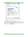
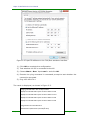
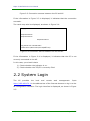
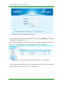
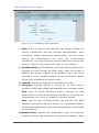
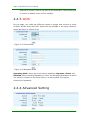
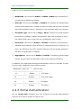
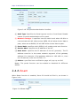
In-Wall AP Series User Manual
(Applicable to MT-W101, MT-W121, MT-W104G)
V1.0
Maipu Communication Technology Co., Ltd
No. 16, Jiuxing Avenue
Hi-tech Park
Chengdu, Sichuan Province
People’s Republic of China - 610041
Tel: (86) 28-85148850, 85148041
Fax: (86) 28-85148948, 85148139
URL: http: // www.maipu.com
Email: [email protected]
Maipu Confidential & Proprietary Information
Page 1 of 34
Maipu In-Wall AP Series User Manual
Copyright
Copyright ©2013, Maipu Communication Technology Co., Ltd. All Rights Reserved.
No part of this manual may be reproduced or transmitted in any form or by any means
without prior written consent of Maipu Communication Technology Co., Ltd.
and
are trademarks of Maipu Communication Technology Co., Ltd.
All other trademarks that may be mentioned in this manual are the property of their
respective owners.
The information in this document is subject to change without notice. Every effort has
been made in the preparation of this document to ensure accuracy of the contents, but all
statements, information, and recommendations in this document do not constitute the
warranty of any kind, express or implied.
Security Statement
Important! Before powering on and starting the product, please read the security and
compatibility information of the product.
Environmental protection
This product has been designed to comply with the environmental protection requirements.
The storage, use, and disposal of this product must meet the applicable national laws and
regulations.
Maipu Confidential & Proprietary Information
Page 2 of 34
Maipu In-Wall AP Series User Manual
Preface
Thank you for using Maipu high-performance wireless access point (AP). The AP
is the next-generation wireless access point of high performance based on
802.11n and can provide the wireless access rate six times of the traditional
802.11a/b/g. In addition, the AP can cover more extensive area.
The AP supports both the Fat and Fit work mode and can switch flexibly between
these two modes as required by the network planning. The AP needs to
cooperate with the wireless network controller when acting as a fit AP and can
be deployed independently when acting as a fat AP. By supporting the Fat and Fit
work modes, the AP can be smoothly upgraded to the large-scale network from
the small-size WLAN network. This can greatly protect the user investment.
The AP works at the 2.4GHz band and adopts the MIMO and OFDM technologies.
The AP can provide the data transmission rate with a maximum of 150 Mbps for
single channel and a maximum of 300 Mbps for the dual-channel.
In addition, the AP has the comfortable interface and combines the simple
interface, which enables the user to complete the setting quickly and enables
the user to use the AP more convenient and efficient.
Chapter 1: product overview, briefly describes the main AP feature and product
specifications.
Chapter 2: detailed configuration guide, instructs you to configure the AP
parameters and advanced features.
Maipu Confidential & Proprietary Information
Page 3 of 34
Maipu In-Wall AP Series User Manual
Contents
Copyright ....................................................................................................................................... 2
Preface ............................................................................................................................................ 3
1 Product Introduction ............................................................................................................. 6
1.1 Overview ........................................................................................................................ 6
1.2 Main Features and Specifications ......................................................................... 7
1.2.1 Main Features........................................................................................................... 7
2 Detailed Configuration Guide ............................................................................................. 9
2.1 PC Configuration ......................................................................................................... 9
2.2 System Login.............................................................................................................. 12
2.3 System Status ........................................................................................................... 14
2.3.1 Device Information ................................................................................................. 14
2.3.2 WLAN Status........................................................................................................... 14
2.3.3 WLAN Client ........................................................................................................... 14
2.3.4 System Load ........................................................................................................... 15
2.3.5 Network Detection ................................................................................................. 16
2.4 Wireless Configuration ............................................................................................ 16
2.4.1 Wireless Parameter ................................................................................................ 16
2.4.2 SSID......................................................................................................................... 17
2.4.3 WDS ........................................................................................................................ 19
2.4.4 Advanced Setting .................................................................................................... 19
2.4.5 Portal Authentication ............................................................................................. 20
2.4.6 Roam ...................................................................................................................... 21
2.4.7 MAC Filtering.......................................................................................................... 22
2.5 Network Configuration ............................................................................................ 22
2.5.1 IP Address ............................................................................................................... 22
2.5.2 MAC Clone .............................................................................................................. 23
2.5.3 DNS Setting............................................................................................................. 24
2.5.4 DHCP Patch ............................................................................................................. 24
2.5.5 DHCP Band ............................................................................................................. 24
2.5.6 LLDP ........................................................................................................................ 25
2.6 VLAN Configuration .................................................................................................. 25
2.6.1 802.1Q VLAN .......................................................................................................... 25
2.7 System Setting .......................................................................................................... 26
2.7.1 Management Mode ............................................................................................... 26
2.7.2 Host Name .............................................................................................................. 26
Maipu Confidential & Proprietary Information
Page 4 of 34
Maipu In-Wall AP Series User Manual
2.7.3 Administrator Setting ............................................................................................. 27
2.7.4 Profiles.................................................................................................................... 27
2.7.5 Firmware Upgrade .................................................................................................. 28
2.7.6 System Time ........................................................................................................... 29
2.7.7 OUI Update ............................................................................................................. 30
2.7.8 AP Restart ............................................................................................................... 30
2.8 System Log ................................................................................................................. 30
2.8.1 Event Log ................................................................................................................ 31
2.8.2 Alarm Log ............................................................................................................... 31
2.8.3 Security Log ............................................................................................................ 32
2.8.4 Network Log ........................................................................................................... 32
Appendix ...................................................................................................................................... 33
Hardware Restoration Configuration ................................................................................. 33
Maipu Confidential & Proprietary Information
Page 5 of 34
Maipu In-Wall AP Series User Manual
1 Product Introduction
1.1 Overview
The AP is the next-generation wireless access point of high performance based
on 802.11n and can provide the wireless access rate six times of the traditional
802.11a/b/g. In addition, the AP can cover more extensive area.
The AP supports both the Fat and Fit work mode and can switch flexibly between
these two modes as required by the network planning. MP101 needs to
cooperate with the wireless network controller when acting as a fit AP and can
be deployed independently when acting as a fat AP. By supporting the Fat and Fit
work modes, the AP can be smoothly upgraded to the large-scale network from
the small-size WLAN network. This can greatly protect the user investment.
The AP works at the 2.4GHz band and adopts the MIMO and OFDM technologies.
The AP can provide the data transmission rate with a maximum of 150 Mbps for
single channel and a maximum of 300 Mbps for the dual-channel.
Maipu Confidential & Proprietary Information
Page 6 of 34
Maipu In-Wall AP Series User Manual
1.2 Main Features and
Specifications
1.2.1 Main Features
Easy to deploy
The AP can automatically detect the AC and delivers the configuration via the AC.
The wireless network can be enabled for the AP zero configuration. The AP can
integrate with the existing AP, firewall, authentication server, and other network
architecture seamlessly without changing the existing network architecture.
High-rate broadband wireless access
The AP supports 802.11a/b/g/n and works at the 2.4GHz band, providing
high-rate wireless access service of high quality for users.
Centralized management
The AP can act as a fit AP and cooperate with the AC. The AC uniformly controls
all the fit APs in the network and the status of all the devices can be viewed.
Comparing with the traditional fat AP, the AC and the fit AP application mode
greatly facilitate the administrator to manage the entire network.
AP centralized upgrade
The AP can achieve the centralized management by the wireless network
controller in the network and uniformly upgrade the AP to the latest version. The
AP can apply new firmware automatically without manual interference, which
reduces the workload of network maintenance. The feature is especially
important to the large-scale network.
Maipu Confidential & Proprietary Information
Page 7 of 34
Maipu In-Wall AP Series User Manual
User isolation policy
The AP supports the isolation between the wireless users. When this function
enabled, two wireless clients cannot communicate directly. The wireless client
can intelligently visit the upstream wired network. When applying this feature,
the carrier can force the wireless user to the specified gateway or server for
billing or more secure authentication, realizing the hotpot application.
Multiple forms and convenient installation
This series APs have multiple form design and can be applicable to different
installation scenarios. There is no need to smash the wall to lay out cables and
furnish the wall for the second time. The AP provides the wireless coverage
based on the wired network and can be installed conveniently and quickly.
Cooperating with the wireless network controller, the wireless AP can achieve
plug-and-play and AP zero configuration, and all the AP management, control,
and configuration are completed by the AC. The network management
personnel does not need to manage and maintain the mass of APs one by one,
and all actions, such as the configuration, firmware upgrade, and security policy
update can be delivered uniformly by the AC.
Maipu Confidential & Proprietary Information
Page 8 of 34
Maipu In-Wall AP Series User Manual
2 Detailed Configuration
Guide
2.1 PC Configuration
To facilitate the user management, the AP integrates the web management
function. Through this function, we can realize various management functions in
a simple mode to facilitate using. When the user configures the hardware, the
user can use the PC to configure the AP.
Through the PC connected to the AP, the user can easily perform the web
management after the following configuration.
The default IP address of the AP is 192.168.170.1 and this parameter can be set
as required. The following takes the default value as an example. The PC is set
by the following steps:
1) Connect the PC to the port of the AP.
2) Set the IP address of the PC.
3) Select Network > Network > Local Connection.
4) Right-click Local Connection and click Properties on the displayed
menu.
5) Select Internet Protocol Version 4 (TCP/IPv4), as shown in Figure
2-1.
Maipu Confidential & Proprietary Information
Page 9 of 34
Maipu In-Wall AP Series User Manual
Figure 2-1 Select Internet TCP/IP protocol on the attribute window
Click Properties to set the IP address of the PC.
On the Internet Protocol Version 4 (TCP/IPv4) Properties dialog box,
choose Use the following IP address and input 192.168.170.xxx in IP
address, 255.255.255.0 in Subnet mask, and input 192.168.170.1 (default IP
address of the AP) in Default gateway.
Maipu Confidential & Proprietary Information
Page 10 of 34
Maipu In-Wall AP Series User Manual
Figure 2-2 Input IP address on the TCP/IPv4 attribute interface
1) Click OK to complete the configuration.
2) Test whether the PC is connected to the AP.
3) Choose Start > Run. Input cmd > and click OK.
4) Execute the ping command in command prompt to test whether the
connection succeeds.
5) Ping 192.168.170.1.
The result is displayed, as shown in Figure 2-3.
Pinging 192.168.170.1 with 32 byte of data:
Replyfrom 192.168.170.1:bytes=32 time<10ms TTL=64
Replyfrom 192.168.170.1:bytes=32 time<10ms TTL=64
Replyfrom 192.168.170.1:bytes=32 time<10ms TTL=64
Replyfrom 192.168.170.1:bytes=32 time<10ms TTL=64
Ping statistics for 192.168.170.1:
Packets:Sent=4,Received=4,Lost=0(0% loss).
Maipu Confidential & Proprietary Information
Page 11 of 34
Maipu In-Wall AP Series User Manual
Figure 2-3 Connection success between the PC and AP
If the information in Figure 2-3 is displayed, it indicates that the connection
succeeds.
The result may also be displayed, as shown in Figure 2-4.
Pinging 192.168.170.1 with 32 byte of data:
Requesttimed out.
Requesttimed out.
Requesttimed out.
Ping statistics for 192.168.170.1:
Packets:Sent=4,Received=4,Lost=0(100% loss).
Figure 2-4 Connection failure between the PC and AP
If the information in Figure 2-4 is displayed, it indicates that the PC is not
correctly connected to the AP.
In this case, you should check:
1) Check whether the indicator is on.
2) Check whether the TCP/IP is correctly filled.
2.2 System Login
The
AP
provides
the
local
and
remote
web
management.
Input
http://192.168.170.1 in the address bar of the Internet browser to log in to the
AP configuration interface. The login interface is displayed, as shown in Figure
2-5.
Maipu Confidential & Proprietary Information
Page 12 of 34
Maipu In-Wall AP Series User Manual
Figure 2-5 The AP configuration interface
Both the default user name and password of the AP are admin and the default
IP address is 192.168.170.1.
After correctly logging in to the system, the homepage is displayed, as shown in
Figure 2-6. The homepage may vary slightly for different models.
Figure 2-6 The homepage displayed after logging in to the system
The homepage displays the system wireless status of the device, including the
SSID containing APs and number of connected APs.
Maipu Confidential & Proprietary Information
Page 13 of 34
Maipu In-Wall AP Series User Manual
2.3 System Status
2.3.1 Device Information
On the Device Info interface, the device information of the AP, including
Hostname, Device Model, Serial Number, Firmware Version, MAC
Address, and Uptime, is displayed as shown in Figure 2-7.
Figure 2-7 The device information interface
2.3.2 WLAN Status
On the WLAN Status interface, the status information of the AP wireless
connection, including SSID, Encryption, Band, Channel, and Broadcast
SSID, is displayed as shown in Figure 2-8.
Figure 2-8 The WLAN status interface
2.3.3 WLAN Client
On the WLAN Clients interface, the information of the host that is successfully
connected to the AP can be viewed, as shown in Figure 2-9.
Maipu Confidential & Proprietary Information
Page 14 of 34
Maipu In-Wall AP Series User Manual
Figure 2-9 The WLAN client information
(1) MAC Address: specifies the MAC address of the host that is
successfully connected to the AP.
(2) Tx Size: specifies the data traffic that sent by the host.
(3) Rx Size: specifies the data traffic received by the host.
(4) Tx Rate: specifies the current rate of sending data package by the host.
(5) RSSI: specifies the signal strength between the host and the AP.
(6) Link Time: specifies the time that the host is connected to the AP.
2.3.4 System Load
On the System Load interface, you can view the current AP memory and CPU
load, as shown in Figure 2-10.
Figure 2-10 The system load interface
(1) Auto refresh: specifies whether to automatically refresh the current
system load status.
(2) Service:
specifies
whether
to
enable the
system
load
alarm
mechanism.
Maipu Confidential & Proprietary Information
Page 15 of 34
Maipu In-Wall AP Series User Manual
CPU Threshold: specifies the CPU alarm threshold.
Memory Threshold: specifies the memory alarm threshold.
2.3.5 Network Detection
On the detection interface, you can detect the network connection status(ping
test is used here.), as shown in Figure 2-11.
Figure 2-11 The ping detection interface
(1) Detection Address: specifies the target host for the system sending
the ICMP packet.
(2) Detection Packets: specifies the number of ICMP packets sent by the
system. The number must an integer from 1 to 10.
(3) Detection: notifies the system to begin to send the ICMP packet.
Figure 2-12 The result of network detection.
2.4 Wireless Configuration
2.4.1 Wireless Parameter
On the Basic Settings interface, you can configure SSID, network band, and
network channel of the AP.
Choose WEB Management > 2.4 GHz WLAN > Basic Settings to enter the
Basic Settings interface, as shown in Figure 2-13.
Maipu Confidential & Proprietary Information
Page 16 of 34
Maipu In-Wall AP Series User Manual
Figure 2-13 The wireless parameter interface
(1) WLAN: specifies whether to enable or disable the wireless network
function of the AP.
(2) Band: specifies the network protocol mode that the AP works at.
Currently, the AP supports the combination of the 802.11B, 802.11G,
802.11N, B+G, G+N, and B+G+N six protocols.
(3) Channel: indicates the wireless channel. It is the data signal
transmission channel considering the wireless signal as transmission
media. When multiple devices exist in the area covered by the AP signal,
set different channels to avoid interference. The AP has a total of 1 to 11
channels.
(4) RF Power: adjusts the output power of the AP.
(5) User Isolation: the wireless clients cannot communicate with each
other when the function is enabled.
2.4.2 SSID
On the Add interface, you can configure the SSID information of the AP.
Choose WEB Management > 2.4GHz WLAN > SSID to enter the Add
interface, as shown in Figure 2-14.
Maipu Confidential & Proprietary Information
Page 17 of 34
Maipu In-Wall AP Series User Manual
Figure 2-14 The adding SSID interface
(1) SSID: short for Service Set Identifier, can divide a WLAN into
several subnetworks requiring different authentications. Each
subnetwork needs independent authentication and only users
passing
the
authentication
can
enter
the
corresponding
subnetwork. This can prevent the unauthorized users entering this
network. That is to say, SSID is the name of your network.
(2) Broadcast SSID: specifies whether to allow the wireless network to be
searched by others through the SSID name. When this function is
disabled, the wireless network is still available, but it will not be
searched in others' available network list and the wireless network
efficiency will be affected to a certain extent.
(3) VLAN ID: specifies the VLAN ID to be allocated to the AP.
(4) Encryption: specifies whether to encrypt the set SSID. The AP
provides the WEP, WPA, WPA2, and WPA/WPA2 four encryption modes.
WEP: short for Wired Equivalent Privacy, encrypts the data
transmitted in wireless mode between two devices to prevent the
unauthorized user to bug or invade the wireless network.
WPA: short for Wi-Fi Protected Access, has the WPA and WPA2
standards and protects the Wi-Fi security. It is generated based on
several serious weaknesses found in the last generation of system WEP
by the researcher.
(5) Authentication: specifies the authentication type. Two types are
available, Personal (Pre-shared Key) and Enterprise (Radius). When
Maipu Confidential & Proprietary Information
Page 18 of 34
Maipu In-Wall AP Series User Manual
Personal is chosen, enter a key with 8~63 characters. When Enterprise
is chosen, a Radius server will be needed.
2.4.3 WDS
On this page, you could set different modes to bridge and connect to other
wireless Access Point while still keeps the two WLANs in the same network,
shown as Figure 2-15 and 2-16.
Figure 2-15 Client Mode
Figure 2-16 Repeater Mode
Operating Mode: there are three options available: Repeater, Client, and
Disabled. When choosing Repeater or Client, the Wireless parameters of which
you want to connect to should be filled in, including SSID, Encryption,
Channel(for Repeater).
2.4.4 Advanced Setting
Maipu Confidential & Proprietary Information
Page 19 of 34
Maipu In-Wall AP Series User Manual
Figure 2-17 The advanced setting interface
(1) Bandwidth: can be set to 20MHz or 40MHz. 40MHz here indicates the
coexistence of 20MHz and 40MHz.
(2) Short GI: can be set to Enable or Disable. GI indicates the transmission
interval of the data block. A short GI results in faster transmission rate and
also high probability of error, especially in the multipath effect environment.
(3) Preamble Type: can be set to Long or Short. The 802.11 frame contains
three parts: preamble, header, and payload. When the preamble is short,
the transmission rate is high, but the compatibility may be poor.
(4) Protection: can be set to Enable or Disable. Protection, b/g Protection,
indicates the protection mode of 802.11b. Because the work modes of b, g,
and n are different, the entire network efficiency will be greatly reduced if
the 802.11b protection is enabled.
(5) Aggregation: can be set to Enable or Disable. Combining multiple data
frames as one frame can obviously improve the network efficiency.
In addition, the relationship among the bandwidth, short GI, and Max Tx rate
can be simply explained in the following mode.
-------------------------------Bandwidth | short GI | Max TX Rate
---------------------------------------------20
|
Enable
| 150 Mbps
---------------------------------------------20
|
Disable
| 135 (130) Mbps
----------------------------------------------40
|
Enable
| 300 Mbps
---------------------------------------------40
|
Disable
| 270 Mbps
2.4.5 Portal Authentication
On the Portal Auth interface, you can configure the portal authentication
function of the AP, as shown in Figure 2-18.
Maipu Confidential & Proprietary Information
Page 20 of 34
Maipu In-Wall AP Series User Manual
Figure 2-18 The portal authentication interface
(1) Auth Type: Specifies the Portal type as Local or Cloud Portal. Disable
means no portal authentication will be used.
(2) Network Outage: it specifies how AP would work when AP fails to
communicate with AC. When set as OPEN, AP will allow clients’ data to
pass; when set as BLOCK, AP will NOT allow clients’ data to pass.
(3) Portal Auth: specifies which SSID(s) will enable portal auth function.
(4) Service Addr: specifies the IP address of the AC.
(3) Auth Addr: specifies the IP address of the AC generally. The IP
address must be in the same network segment of the gateway
address. For example, if the gateway address is 192.168.1.1, then
the IP address must be 192.168.1.X.
(4) Others: specifies how certification page will pop up on iOS.
Notes: The portal function can be enabled or disabled for different
SSIDs.
2.4.6 Roam
When Roam function is enabled, Serer IP should be filled in, as shown in
Figure 2-19.
Figure 2-19 Roam Page
Maipu Confidential & Proprietary Information
Page 21 of 34
Maipu In-Wall AP Series User Manual
2.4.7 MAC Filtering
On the MAC Filter interface, you can configure the MAC filtering function of the
AP.
Choose WEB Management > 2.4GHz WLAN > MAC Filter to enter the MAC
Filter interface, as shown in Figure 2-20.
Figure 2-20 The MAC filtering interface
(1) Status Operation: specifies the filtering rule for the content in the
MAC list. Blacklist indicates that the content is blocked and
Whitelist indicates that the content is allowed.
(2) MAC List: fills the MAC information to be filtered.
2.5 Network Configuration
2.5.1 IP Address
On the IP Address interface, you can configure the IP address, subnet mask,
and gateway of the AP. Through these functions, you can specify the AP to
register on a certain AC. If the AP and AC do not exist in the same LAN, the
gateway and IP address of the AP need to be filled. If the AP and AC exist in the
same LAN, the information can be omitted.
Maipu Confidential & Proprietary Information
Page 22 of 34
Maipu In-Wall AP Series User Manual
Choose WEB Management > Network > IP Address to enter the IP
Address interface, as shown in Figure 2-21.
Figure 2-21 The IP address interface
(1) IP Address: specifies the IP address of the AP manually.
(2) Netmask: specifies the subnet mask of the LAN in which the specified
AC locates.
(3) Gateway: specifies the gateway address of the LAN in which the AC
locates.
2.5.2 MAC Clone
This function allows the user to modify the MAC address and MTU value of the AP.
This function is usually used before the old AP replaces the new AP to prevent
causing a series of problems due to MAC address changing. The MAC address of
the old AP can be copied to the new AP. Generally, MTU is set to the default
value and do not need to be modified.
Figure 2-22 The MAC clone interface
Maipu Confidential & Proprietary Information
Page 23 of 34
Maipu In-Wall AP Series User Manual
2.5.3 DNS Setting
This function allows the user to modify the DNS configuration information of the
AP and is usually used for the tracert detection function of the AP.
Figure 2-23 The DNS setting interface
2.5.4 DHCP Patch
Figure 2-24 The DHCP patch interface
For some operating systems, such as Win7 and Mac OS X, the WLAN clients only
receive the unicast DHCP packets, and do not receive the broadcast DHCP
packets. Therefore, the DHCP patch function is added to the AP to solve the
problem that some systems cannot obtain the IP address.
2.5.5 DHCP Band
When enabled, DHCP packet will only send to the specified DHCP Sever specified
here.
Note: AP would use unicast instead of broadcast packet when it’s enabled. Make
sure the DHCP server would accept the DHCP unicast packet.
Figure 2-25 DHCP Band
Maipu Confidential & Proprietary Information
Page 24 of 34
Maipu In-Wall AP Series User Manual
2.5.6 LLDP
The Link Layer Discovery Protocol or LLDP is a vendor-neutral Layer 2 protocol
that allows a network device to advertise its identity and capabilities on the local
network.
On this LLDP Page, you could change the parameters including Mode, Tx
Interval, Time to Live and Fast Change.
Figure 2-26 LLDP
2.6 VLAN Configuration
2.6.1 802.1Q VLAN
Figure 2-27 The 802.1Q VLAN interface
(1) VLAN ID: If the AC manages the AP in the LAN, the VLAN ID of the AC
must be added and the AC can communicate with the AP and manages
the AP.
(2) LAN VLAN ID: fills the VLAN ID to be allocated to the AP.
Notes:
Only when Mode is set to Manual setting, the VLAN option is available.
Maipu Confidential & Proprietary Information
Page 25 of 34
Maipu In-Wall AP Series User Manual
2.7 System Setting
2.7.1 Management Mode
Choose WEB Management > System > Management to enter the
Management interface, as shown in Figure 2-28.
Figure 2-28 The management mode interface
(1) By AC: Mode for the AP is set to By AC by default. When the AP starts,
the AP will automatically search the wireless AC in the LAN, register on
the AC automatically, and download default template configuration
from the AC, and the configuration takes effect immediately. For details,
refer to the AP template description in the AC manual.
(2) Manual Setting: when the AP needs to be managed independently,
enable the Manual setting. When this setting is enabled, you can
modify the wireless parameters on the AP web page.
(3) Save: Click Save after filling the AP static configuration to enable the
parameter to take effect.
2.7.2 Host Name
On the Hostname interface, you can change the host name of the AP.
Hostname is set to the SN of the AP by default, as shown in Figure 2-29.
Figure 2-29 The host name interface
Maipu Confidential & Proprietary Information
Page 26 of 34
Maipu In-Wall AP Series User Manual
2.7.3 Administrator Setting
On the Administrator interface, you can set the user name, password, and
administrative authority of the user for logging in to the web management page.
Choose WEB Management > System > Administrator to enter the
Administrator interface, as shown in Figure 2-30.
Figure 2-30 The administrator setting interface
(1) User name: specifies the user name for the user logging in to the
system.
(2) Password: specified the password for the user logging in to the
system.
(3) Confirm password: specifies the password conformation and must be
identical to the previously inputted password.
(4) Authority: specifies the authority for the user operating the system.
2.7.4 Profiles
On the Profile interface, you can choose Restore factory, Restore backup,
and Save current.
Maipu Confidential & Proprietary Information
Page 27 of 34
Maipu In-Wall AP Series User Manual
Choose WEB Management > System > Profiles to enter the Restore
factory, Restore backup, and Save current interfaces, as shown in Figure
2-31.
Figure 2-31 The configuration file interface
Restore configuration: click to restore to the default configuration.
2.7.5 Firmware Upgrade
Firmware upgrade is a necessary function for the network product. The software
must be optimized and upgraded continuously to satisfy the changeable
network environment and meet different requirements. Whether the software
upgrade can be promoted to meet the changeable requirements is more and
more concerned by users.
Choose WEB Management > System > Firmware Update to enter the
Firmware Update interface, as shown in Figure 2-32.
Figure 2-32 The firmware upgrade interface
Current version: displays the software version number used by the current
system.
Upgrade file: specifies the software package for upgrading the system, which
is provided by the manufacturer.
Notes:
1) All the options with asterisk (*) are mandatory.
Maipu Confidential & Proprietary Information
Page 28 of 34
Maipu In-Wall AP Series User Manual
2) There is risk for firmware upgrading. Do not pause during the upgrading.
The whole upgrading process will take about two minutes. A message
will be prompted when the upgrade succeeds, therefore please wait
patiently during the upgrading.
3) After the upgrade succeeds, reboot the AP manually to take the new
version into effect. If the upgrade error message is prompted, do not
reboot the AP and just repeat the upgrade operations until the
upgrade succeeds. If the upgrade error occurs and the AP is powered
off or the AP is powered off during upgrading, the system will fail to be
started. In this case, contact the technical personnel for support.
2.7.6 System Time
On the System time interface, set the AP system time, as shown in Figure
2-33.
Figure 2-33 The system time interface
(1) Update method: specifies the mode for modifying the time. It can be
set to Synchronization time and Manual Setup.
(2) Computer time: specifies the time synchronous with the computer.
(3) System time: specifies the time displayed on the AP time setting
interface.
(4) System timezone: specifies the time zone in which the user locates.
(5) Network time: the AP will be automatically synchronized the time with
the time server in a regular period.
(6) Time service: the user can choose whether to enable the time
synchronization function.
Maipu Confidential & Proprietary Information
Page 29 of 34
Maipu In-Wall AP Series User Manual
2.7.7 OUI Update
You can update the OUI info by enabling OUI update on this page. The update
frequency could also be configured here.
Figure 2-34 OUI Update
2.7.8 AP Restart
On the Restart interface, you can restart the AP.
Choose WEB Management > System > Restart to enter the Restart
interface, as shown in Figure 2-35.
Figure 2-35 The restart interface
2.8 System Log
The AP running status is recorded and saved as a log to help us locate the fault,
troubleshoot, and manage network security, and help us to analyze whether the
AP is normal and whether the network is healthy.
Maipu Confidential & Proprietary Information
Page 30 of 34
Maipu In-Wall AP Series User Manual
2.8.1 Event Log
Choose WEB Management > System Log > Event Log to enter the Event
Log interface, as shown in Figure 2-36.
Figure 2-36 The event log interface
(1) Time: specifies the instant time when the system changes.
(2) Level: can be classified into Info and Warning. Info records the
running events and Warning reminds you notice based on the running
event recorded.
(3) Message: records the running event.
(4) Refresh: click Refresh to refresh the latest log information.
(5) Clear: click Clear to clear the log information.
(6) Export: click Export to export the log to a text.
2.8.2 Alarm Log
Choose WEB Management > System Log > Alarm Log to enter the Alarm
Log interface, as shown in Figure 2-37.
Figure 2-37 The alarm log interface
Maipu Confidential & Proprietary Information
Page 31 of 34
Maipu In-Wall AP Series User Manual
(1) Time: specifies the instant time when the system changes.
(2) Level: contains Warning. Warning reminds you notice.
(3) Message: records the running event.
2.8.3 Security Log
The security log contains the log tracing events, such as logging in to the
system, change the visit authority, and start and shut down the system, as
shown in Figure 2-38.
Figure 2-38 The security log interface
(1) Time: specifies the instant time when the system changes.
(2) Level: can be classified into Info and Warning. Info records the
running events and Warning reminds you notice based on the running
event recorded.
(3) Message: records the running event.
2.8.4 Network Log
Choose WEB Management > System Log > Network Log to enter the
Network Log interface, as shown in Figure 2-39.
Figure 2-39 The network log interface
(1) Time: specifies the instant time when the system changes.
(2) Level: can be classified into Info and Warning. Info records the
running events and Warning reminds you notice based on the running
event recorded.
(3) Message: records the running event.
Maipu Confidential & Proprietary Information
Page 32 of 34
Maipu In-Wall AP Series User Manual
Appendix
Hardware Restoration
Configuration
If the AP password loss or other fault occurs, you can press the Reset button on
the front panel to clear the configuration and restore the AP to the default
setting.
Operation Steps:
Step 1: Power on the AP and start the AP to the normal work status. (The AP can
be pinged through via the PC.)
Step 2: Use a sharp object to press the Reset button on the front panel and
release the Reset button until the ping value is changed to a larger value,
as shown in the following figure.
Maipu Confidential & Proprietary Information
Page 33 of 34
Maipu In-Wall AP Series User Manual
Step 3: Enable the AP to reboot automatically. The system restores the default
configuration when the AP is rebooted normally.
Notes:
(1) This function will take effect when the AP is started normally. (The AP
can be pinged through via the PC.)
(2) Press the Reset button and do not release in the midway.
(3)Contact the technical personnel for support if the system does not work
normally.
Maipu Confidential & Proprietary Information
Page 34 of 34