1
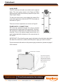
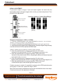
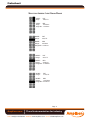
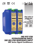
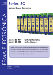
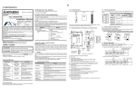
Datasheet
ISC-POT
ISC-RES
ISOLATED SIGNAL CONVERTER
3 WAY ISOLATION
MODEL : RES
MODEL : POT
USER’S MANUAL
Amplicon.com
IT and Instrumentation for industry
Sales: +44 (0) 1273 570 220 Website: www.amplicon.com Email: [email protected]
Datasheet
INDEX
GENERAL INFORMATION .................................................. 3
QUICK GUIDE .................................................................... 4
POWER SUPPLY CONNECTIONS ................ 4
SIGNAL ADJUSTMENT .................................. 5 and 6
DIMENSIONS AND CONNECTIONS .............. 7
TECHNICAL DATA .............................................................. 8
INPUT SIGNAL ............................................... 8
OUTPUT SIGNAL ........................................... 8
GENERAL CHARACTERISTICS ..................... 9
POWER SUPPLY .......................................... 9
MECHANICAL DIMENSIONS ......................... 9
GALVANIC ISOLATION LEVELS ................... 9
MATERIALS ................................................... 9
CAUTIONS, WARNINGS AND NOTES ............................... 10
CE DECLARATION OF CONFORMITY ............................... 12
WARRANTY, RETURNS FOR REPAIR .............................. 13
NOTES ............................................................................... 14
Page 2
Amplicon.com
IT and Instrumentation for industry
Sales: +44 (0) 1273 570 220 Website: www.amplicon.com Email: [email protected]
Datasheet
GENERAL INFORMATION
The ISC series of Isolated Signal Converters, allow to convert process signals,
temperatures, electrical signals, etc, to current loops or voltage signals for further
retransmision, while introducing into the system galvanic isolation barriers between
the input, the output and the power supply circuits.
The ISC series of Isolated Signal Converters, offer an excellent relation between
signal conversion speed and measure accuracy. Offering a 0.2% accuracy and a
70ms response time (depends on the model), these units can process information
coming from probes or transducers, in such a way that can be quickly retransmitted
in a fast and accurate form to remote data acquisition systems or PLC’s. The isolated
signal converters of the ISC series are ideal to integrate into 12 bit data acquisition
systems.
Its powerful galvanic isolation of 3.500 V introduces high security to the measuring
systems, preventing the propagation of those phenomenon which usually cause
damage, such as transient peaks or energy shocks in any of the circuits of the
system. The galvanic isolation also acts as a strong CE barrier. The decoupling
created between the circuits avoids pernicious effects on the output, such as ground
loops or signal leaks, which distort the acquired data and are extremely difficult to
isolate once introduced into the signal.
The isolation offered by the ISC series of Isolated Signal Converters is a 3 way
isolation. Thus, all the benefits exposed above are applicable to any of the three
circuits composing the instrument : input, output and power.
Recalibration of the instruments is realized in a fast and easy way. Opening the frontal
cover grants access to the configuration jumpers. Additional Span and Offset
potentiometers are directly accessible from the frontal part. These potentiometers
are highly decoupled, minimizing the iterations needed to obtain a correct adjustment.
In order to obtain a higher and quickest benefit of the ISC units, we recommend you
to read carefully the information provided in this manual before proceeding to the
installation of the instrument. In this manual you will find all technical data, both
electrical and mechanical, needed for a correct instalation and utilization.
Note : The units of the ISC Isolated Signal Converters have attached a characteristics
label on the side of the instrument. Check that this information matches with your
requirements for this specific application, and very specially check the value and type
of the Power Supply.
Page 3
Amplicon.com
IT and Instrumentation for industry
Sales: +44 (0) 1273 570 220 Website: www.amplicon.com Email: [email protected]
Datasheet
QUICK GUIDE
The ISC units have a frontal cover which can be opened
down. This cover gives access to the Span and Offset
potentiometers, and to the selection jumpers for input and
output signal ranges.
To open the frontal cover, press slightly the sides of the
cover at the upper side, close to the OUTPUT terminals, as
indicated on Figure1.
The cover is free to open down, as shown on Figure2.
POWER SUPPLY CONNECTIONS
ISC units are powered through the plug-in terminal
positioned on the upper side of the instrument. This terminal is placed in a transverse axis, different from the other
terminals. Close to the power supply terminal there is a
small yellow label with indications on the connections for
AC and DC
FIGURE1
FRONT VIEW WITH COVER
IMPORTANT !! Check that the power supply indicated on the white label attached to
the side of the instrument, matches with the power supply you want to connect.
For more accurate information on the power supply connections, please see page 6
of this manual.
FIGURE2
S IDE VIEW
POWER SUPPLY TERMINAL
FRONT COVER OPENING:
ACCESS TO JUMPERS FOR
INPUT AND OUTPUT RANGE
SELECTION, AND ACCESS TO
SPAN AND OFFSET ADJUST
POTENTIOMETERS
Page 4
Amplicon.com
IT and Instrumentation for industry
Sales: +44 (0) 1273 570 220 Website: www.amplicon.com Email: [email protected]
Datasheet
SIGNAL ADJUSTMENT
To proceed to adjust a range of input and output signals, first select with the
appropriate jumpers, the signal ranges which include your desired adjustment. Then
proceed to the adjustment.
Selection Jumpers : Output Signal Range
SELECTION JUMPERS
OUTPUT SIGNAL
SPAN POTENTIOMETER
OFFSET POTENTIOMETER
0/20mA
(4/20mA)
0/10Vdc
0/1Vdc
SELECTION JUMPERS
INPUT SIGNAL
FRONT VIEW
WITHOUT
COVER
Example of Adjustment : 0/100% = 0/10Vdc
1.- Connect a potentiometer to the input terminals (8 connector + and 9 connector -.
Terminal 7 connects to the Sense of the potentiometer).
2.- Connect a multimeter to the output signal terminals (4 and 5 for mA or 4 and 6 for Vdc).
3.- Select the jumpers for Signal Output Range (see pag. 5) and Input Signal Range (see pag.
6) so that we have a 0/10 Vdc output and a 0/100% input.
(Values in brackets show an example for conertion 0/100% =0/10Vdc)
4.- Place the potentiometer to measure at position 0% at the input.
Operate on the potentiometer OFFSET, until getting a zero output (0Vdc)
5.- Place the potentiometer to measure at position 100% at the input
Operate on the potentiometer SPAN, until getting the difference between high and
low output levels (10-0=10Vdc)
6.- Place the potentiometer to measure at position 0% at the input
Operate on the potentiometer OFFSET, until getting the low level output signal (0Vdc)
7.- Place the potentiometer to measure at position 100% at the input
Check that the output is the desired high level output (10Vdc)
If higher accuracy is needed, it is possible to operate on the SPAN potentiomenter
during step 6. In this case, repeat also steps 5 and 6.
Most of the input/output combinations required are reached after these three steps.
Close front cover once the adjustment is finished.
Page 5
Amplicon.com
IT and Instrumentation for industry
Sales: +44 (0) 1273 570 220 Website: www.amplicon.com Email: [email protected]
Datasheet
SELECTION JUMPERS : INPUT SIGNAL RANGE
MODEL :
Range :
POT
100% FS
MODEL : RES
Range :
10 KOhms
Range Min : 5 KOhms
MODEL :
Range :
POT
50% FS
MODEL : RES
Range :
5 KOhms
Range Min : 3 KOhms
MODEL :
Range :
POT
25% FS
MODEL : RES
Range :
3 KOhms
Range Min :1.5 KOhms
MODEL :
Range :
POT
12.5% FS
MODEL : RES
Range :
1.5 KOhms
Range Min :750 Ohms
Page 6
Amplicon.com
IT and Instrumentation for industry
Sales: +44 (0) 1273 570 220 Website: www.amplicon.com Email: [email protected]
Datasheet
DIMENSIONS AND CONNECTIONS
Output Connections
Input Connections
POTENTIOMETER
Special Wide for
AC Power models
RESISTANCE
DC
Power Supply
Page 7
Amplicon.com
IT and Instrumentation for industry
Sales: +44 (0) 1273 570 220 Website: www.amplicon.com Email: [email protected]
AC
Power Supply
Datasheet
TECHNICAL DATA : Models ISC-POT and ISC-RES
INPUT SIGNAL FOR MODEL ISC-POT
Input Signal ................................................. Potentiometer 3 Wire
Range
.................................................. from 0 to 100% of potentiometer
Potentiometer Value
................... between 100 Ohms and 1 MegaOhm
Excitation Voltage
................... 1 Vdc
Resistance Ranges selectable ................... 0 / 100 %
0 / 50 %
0 / 25 %
0 / 12.5 %
(Last range allows down to 8%)
INPUT SIGNAL FOR MODEL ISC-RES
Input Signal ................................................. Resistance 2 Wire
Range
.................................................. from 1 KOhm to 10KOhm
Excitation Voltage
................... Resistance x 0.2 mA
Resistance Ranges selectable ................... 0 / 10 KOhm
0 / 5 KOhm
0 / 3 KOhm
0 / 1.5 KOhm
(Last range allows down to 750 Ohms)
(*For more information on ranges, please see page 5)
OUTPUT SIGNAL
Output Signal Ranges in Voltage .................. 0/10Vdc
0/1Vdc
Maximum Voltage Output ............................. 11Vdc approx.
Minimum Voltage Output ............................. -1Vdc approx.
Minimum Load Resistance ............................ ≥1KOhm
Output Signal Ranges in Current ................... 0/20mA (4/20mA)
Maximum Output in Current .......................... 22mA approx.
Minimum Output in Current ........................... -1.5mA approx.
Maximum Load Resistance ........................... ≤400 Ohms
POWER SUPPLY
DC Power Supply ........... 24Vdc ±10%
AC Power Supply ........... 230Vac ±10% 50/60 Hz
115Vac ±10% 50/60 Hz
Consumption .................. <3.8VA
Page 8
Amplicon.com
IT and Instrumentation for industry
Sales: +44 (0) 1273 570 220 Website: www.amplicon.com Email: [email protected]
Datasheet
GENERAL CHARACTERISTICS
Accuracy
................... <0.2% F.S.
Optimized for 12 bit systems
Linearity
................... <0.1% F.S.
Thermal Drift .................. <250 ppm/ºC Tipical
Response Time ............... <70mS (90% of signal)
Bandwith
................... 20Hz (-3dB)
Electrical Connections .... Plug-In Screw Terminals
Maximum Wire Section .. 2.5 mm2
Protection ................... IP-30
Operating Temperature .. from 0 to 60ºC
Storage Temperature ..... from -20 to +70ºC
GALVANIC ISOLATION LEVELS
DC Models
Input - Output ...................... 3500 V
Power-Input ........................ 3500 V
Power- Output ..................... 1000 V
(60 seconds)
(60 seconds)
(60 seconds)
AC Models
Input - Output ...................... 3500 V
Power- Input ....................... 3500 V
Power - Output .................... 3500 V
(60 seconds)
(60 seconds)
(60 seconds)
All isolation levels are tested during 60 seconds time, in Vac TrueRMS mode,
with current leaks <1mA.
Note : Indicated isolation levels are also indicated sometimes as
STRENGTHENED ISOLATION levels, for systems with Polution Level 2
MECHANICAL DIMENSIONS
DC Models
AC Models
DC Weight
AC Weight
.............. 22.5 x 93 x 110 mm
.............. 37.0 x 93 x 110 mm
.............. 120 gr.
.............. 200 gr.
Standard DIN rail mounting, as specified on DIN46277 and DIN EN 50022
37.5 x 7.5 mm (1.38 x 0.3 ´´)
MATERIALS
Box and Cover
Terminals
in Poliamide PA6 UL94 V-2 blue color
in Poliamide UL94 V-0
Page 9
Amplicon.com
IT and Instrumentation for industry
Sales: +44 (0) 1273 570 220 Website: www.amplicon.com Email: [email protected]
Datasheet
CAUTIONS, WARNINGS AND NOTES
INSTALATION
PRECAUTIONS.- The installation and the future use of this unit must be done
by qualified personnel. The unit has not AC (mains) switch,
neither internal protection fuse. It will be in operation as soon as
power is connected. The installation must incorporate an
external mains switch with a protection fuse and also the
necessary devices to protect the operator and the process when using the unit
to a control machine or process where injury to personnel or damage to
equipment or process may occur as a result of failure of the unit.
RECOMMENDED FUSES
Units with Power Supply 24 Vdc
Units with Power Supply 230 Vac
Units with Power Supply 115 Vac
250mA Time Lag Fuse
70mA Time Lag Fuse
100mA Time Lag Fuse
SAFETY PRESCRIPTIONS.- The unit has been designed and tested under
EN-61010-1 rules and is delivered in good conditions. This User’s
Manual contains useful information the user has to respect in order
to warrant a proper function of the unit, and good security conditions.
The unit is designed for internal applications, with good ventilation to
avoid excessive heating. It can occasionally be applied to temperatures
down to 10ºC or up to 70ºC without security degradation. Do all connections
before applying power to the unit. Do not make wiring changes until power is
disconnected from the unit.
Install the unit far from elements generating electric noise, or magnetic fields,
such as power relays, electrical engines, speed regulators, etc. Do not use
until installation is completed.
POWER SUPPLY.- The power supply must be connected to the adequate
terminals 1, 2 and 3. The characteristics of the power supply are shown on the
side label. Please make sure that the unit is correctly connected to a power
supply of the correct voltage and frequency. Do not connect the unit to lines
which are overloaded or which provide power to systems working on ON-OFF
cycles or inductive loads.
ATTENTION : If the power supply is DC voltage, be careful with the polarity
indicated for each terminal.
Page 10
Amplicon.com
IT and Instrumentation for industry
Sales: +44 (0) 1273 570 220 Website: www.amplicon.com Email: [email protected]
Datasheet
SIGNAL WIRING .- Certain considerations must be given when installing the
signal input wires. If the wires are long, they can act as an antenna introducing
electrical noise into the unit. Therefore :
Do not install the signal input wires in the same conduit with power lines, heaters,
solenoids, SCR controls, etc ... and always far from these elements.
When shielded wires are used, leave unconnected the shield on the transmitter
side and conect the other end of the shield to the ground terminal of the machine.
EXCITATION VOLTAGE.- Model ISC-P incorporates an internal power supply for
transducers. The output of this power supply is connected to terminals 7 and 9. Do
not connect these terminals to an external power supply, beacuse both units will be
permantently damaged.
SAFETY CONSIDERATIONS
PRESCRIPTION.- Before starting any operation of adjustment, replacement,
maintenance or repair, the unit must be disconnected from any kind
of power supply. Keep the unit clean, to assure good functioning and
performance. To prevent electrical or fire hazard, do not expose the
unit to excessive moisture. Do not operate the unit in the presence
of flammable gases or fumes, such an environment definetely constitutes a safety
hazard. The unit is designed to be mounted on a metal panel.
If the unit shows signs of damage, is not able to show the expected measures, has
been stored in a bad conditions or a protection failure happened, then do not attempt
to operate, keep the unit out of service and send for repair.
IN CASE OF FIRE
1.- Disconnect the unit from the power supply
2.- Give the alarm according to the local rules
3.- Switch off all air conditioning devices
4.- Attack the fire with carbonic snow, do not use water in any case
WARNING: In closed areas do not use systems with vaporized liquids.
Page 11
Amplicon.com
IT and Instrumentation for industry
Sales: +44 (0) 1273 570 220 Website: www.amplicon.com Email: [email protected]
Datasheet
CE DECLARATION OF CONFORMITY
Manufactured by :
Address :
FEMA ELECTRÓNICA, S.A.
Centro Industrial Santiga
Altimira 14 (Talleres 14, Nave 2)
E 08210-Barberà del Vallès (Spain)
We hereby declare under our responsibility, that the equipments identified below
comply with the following specifications :
Series:
Model :
ISC Series of Isolated Signal Converters
ISC-POT and ISC-RES
DIRECTIVES
EUROPEAN DIRECTIVE FOR LOW VOLTAGE D73/23/CEE AMENDED BY
D93/68/CEE. Equipments powered from 50 to 1000 Vac and/or from 75 to 1500 Vdc.
EUROPEAN DIRECTIVE FOR PRODUCT SAFETY D92/59/CEE
ELECTROTECHNICAL REGULATION FOR LOW VOLTAGE (RBT) ITC21, ITC
29, ITC 35. For equipments with power supply lower than 50Vac and/or 75Vdc.
EUROPEAN DIRECTIVE FOR ELECTROMAGNETIC COMPATIBILITY D89/
336/CEE AMENDED BY D93/68CEE, ACCORDING TO RD1950/1995 (01/12)
REGULATIONS
ELECTRICAL SECURITY:
SUSCEPTIBILITY:
EN61010-1
EN 50082-2
IEC 1000-4-2, EN 61000-4-2, IEC 801-2
ENV 50140, EN 61000-4-4, IEC 801-4 (level 3)
ENV 50204 (level 3)
EMISSION:
EN 50081-2
EN 55011, EN 55014, EN 55022
UNE 21352-76: CEI 359-71
Operating quality expressions for electronic equipments.
UNE 20652-80: CEI 284-68
Behaviour rules inherent to the handling of electronic equipments and other similar technics.
Signed : Alex Pina
Quality Manager
Barberà del Vallès, 2002
Page 12
Amplicon.com
IT and Instrumentation for industry
Sales: +44 (0) 1273 570 220 Website: www.amplicon.com Email: [email protected]
Datasheet
WARRANTY
FEMA ELECTRÓNICA, S.A. warrants this unit to be free of manufacturing defects for
a perior of 24 MONTHS from shipment date. This warranty covers both materials and
manufacturing processes.
This warranty is VOID if the unit shows evidence of damages as a result of misapplication,
accident, misuse or if the product had been tampered or repaired by personnel or
companies without the official authorization of FEMA ELECTRÓNICA, S.A. This
warranty is also VOID for damages caused by defective or inappropriate applications.
In case of malfunction, the unit should be sent to the manufacturer for its evaluation.
Within the warranty period, and always previous examination from FEMA ELECTRÓNICA, S.A., the unit will be repaired or replaced to the discretion of the manufacturer.
Limitation of liability : FEMA ELECTRÓNICA, S.A. shall not be responsible for any
damage or loss to other equipment however caused, which may be experienced as a
result of the installation or use of this product. FEMA ELECTRÓNICA, S.A. liability shall
not exceed the purchase price paid of the product upon which liability is based. In no
event shall FEMA ELECTRÓNICA, S.A. be liable for consequential, inicidental or
special damages
RETURN FOR REPAIR
Ship free of charges and properly packed to the address indicated below, including :
Defective product
Description of the defect
Warranty Data properly filled
FEMA ELECTRÓNICA, S.A.
REPAIRS
Pol.Ind.Santiga (Altimira 14, Talleres 14, Nave 2)
E-08210 BARBERÀ DEL VALLÈS (SPAIN)
WARRANTY DATA
Serial Number :
Series - Model :
Input Signal :
Output Signal :
Power Supply :
Supplied by :
_______________________________________
_______________________________________
_______________________________________
_______________________________________
Date and Stamp
Page 13
Amplicon.com
IT and Instrumentation for industry
Sales: +44 (0) 1273 570 220 Website: www.amplicon.com Email: [email protected]