1
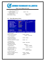
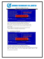
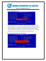
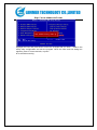
http://www.aimmertech.com AMI-I845GV-ISA Mainboard User’s Manual Rev:1.1 2007.1 http://www.aimmertech.com CONTENTS Chapter 1 Package Contents ..................................................................................................3 Chapter 2 Introduction..............................................................................................................4 Chapter 3 Mainboard Locations..............................................................................................6 Chapter 4 Installation................................................................................................................7 4.1 Jumper Setting and Slot ................................................................................................7 4.2 CPU Installation............................................................................................................8 4.3 Memory installation ....................................................................................................10 4.4 IDE Devices Installation .............................................................................................10 4.5 Other Device Installation ............................................................................................10 Chapter 5 Driver Installation..................................................................................................13 5.1 Installation Directory ..................................................................................................13 5.2 Intel Chipset Software Setup.......................................................................................13 5.3 Sound Driver Setup.....................................................................................................16 5.4 USB 2.0 driver Setup .....................................................................................................18 5.5 VGA driver setup ........................................................................................................18 Chapter 6 BIOS Setup............................................................................................................20 6.1 Main menu .....................................................................................................................20 6.2 Standard CMOS Features............................................................................................21 6.3 Advanced BIOS Features............................................................................................22 6.4 Advanced Chipset Features.........................................................................................24 6.5 Integrated Peripherals..................................................................................................25 6.6 Power Management Setup...........................................................................................26 6.7 PnP/PCI Configurations ..............................................................................................27 6.8 Load Fail-Safe Defaults ..............................................................................................27 6.9 Load Optimized Defaults ............................................................................................28 6.10 Change Password .......................................................................................................29 6.11 Save Exit & Without Save Exit Setup .............................................................................29 http://www.aimmertech.com Chapter 1 Package Contents Your mainboard package contains the following items: 1 One mainboard 2 One 80-Pin Ultra DMA 66/100 IDE drive ribbon cable 3 Software install CD 4 One I/O Backboard http://www.aimmertech.com Chapter 2 Introduction This mainboard has the Intel 845 chipset that contains Intel 82845GV Memory Controller Hub and Intel 82801DB I/O Controller Hub. This mainboard has a Socket-478 support for Intel Pentium4 processors with front-side bus(FSB)speeds up to 400/533,supports DDR200/DDR266 memory bus, supports AC97 audio codec ,integrated AC97 audio that supports full surround sound with up to Two channels, front panel audio output function, provides Ultra DMA66/100 function, the integrated display function technologies without extend display card ,provides Two PCI slots. The mainboard integrated mainboard、VGA card、sound card . Key Features: -Chipset: Intel 845GV chipset GMCH:Intel 82845GV;ICH4:Intel 82801DB -Processor: Supports Intel Celeron CPU Socket 478 CPU Supports Intel Pentium4(Northwood)Socket 478 CPU Supports Intel Pentium4(Willamette)Socket 478 CPU Supports Intel Pentium4(Prescott)Socket 478 CPU Supports Intel Celeron D (Prescott) Socket 478 CPU -Supports 400/533MHz HOST BUS Frequency -Memory Support: Supports DDR200/DDR266 Memory; Two 184-pin DIMM slots for DDR SDRAM memory modules -Integrated display function technologies without extend VGA card Integrated 2D/3D Graphics Controller -USB Ports Six USB ports Supports compliant with Universal Serial Bus Specification Revision 2.0 -IDE Port Provides two channel connecting four IDE drives Supports Ultra ATA66/100 synchronous DMA modes -I/O Ports http://www.aimmertech.com One floppy port support format 360K/720K/1.2M/1.44M/2.88M disk driver One serial ports One parallel port maximum four extra ports) One PS/2 Keyboard port One PS/2 Mouse One MIDI port One IrDA port support 115.2KB/S transfers data. -Onboard AC’97 2.0 specification compliant Support 16bit stereo codec Multiple stereo input mixer Provides onboard Line-in jack, Line-out jack, Microphone-in jack -Expansion Slot Two PCI slots 2.2 specification compliant One AGP 4X One ISA -Dimension Micro ATX form factor http://www.aimmertech.com Chapter 3 Mainboard Locations http://www.aimmertech.com Chapter 4 Installation 4.1 Jumper Setting and Slot FSB CPU Frequency Jumper Setting JUPER AUTO (Default) 400 533 1-2 2-3 OPEN JP1 JP3:Clear CMOS Jumper Setting 1-2(Default) Normal 2-3 Clear CMOS Audio:Front panel Jumper setting PI N Function 1 MIC+ 2 Ground 3 Vbias 4 AuD_Vcc(AVCC) 5 AuD_R_Out 6 AuD_R_Out Back 7 N.C. 8 Key 9 AuD_L_Out 10 AuD_L_Out Back PIN Function USB: Expansion Connector PI N Function PI N Function 1 VCC:Power 2 VCC:Power 3 D-:Data - Signal 4 D-:Data - Signal 5 D+:Data + Signal 6 D+:Data + Signal 7 GND:Ground 8 GND:Ground KEY 1 0 NC 9 Expansion Slots DDR1/DDR2 184 Pin DDR Memory Slots http://www.aimmertech.com PCI1/PCI2 32 bit PCI BUS Expansion Slots AGP AGP Expansion Slots ISA ISA Expansion Slots Connectors PS/2(Bottom) PS/2 Keyboard(Down Purple) PS/2(Top) PS/2 Mouse Header(Up Green) USB1/2 USB1/2 Connector Port USB3 USB3 Connector Port LPT Printer Connector Port VGA VGA Display Connector Port COM1 Serial Ports COM1 Connector Port MIDI MIDI Port LINE IN/MIC OUT/LINE Audio Input/Microphone Output/Audio CD_IN CD-ROM Audio Input Port IDE1/IDE2 Primary IDE/Secondary IDE Port FDD Floppy Disk Drive Connector Port PW1 ATX_20 Power Supply Connector Port PW2 ATX_4 Power Supply Connector Port FAN 1/2 CPU System Fan Port IrDA IrDA Infrared Port Function Port Panel Power Supply LED Pin 1:Power Supply Anode;Pin 3、5: Ground HDD LED Pin 2:Power Supply Anode; Pin 4: LED Signal ATX Power Supply Switch Pin 10:Switch Signal; Pin 8:Power Supply Anode Reset Switch Pin 14:Ground;Pin 16:Reset Signal Speaker Input Pin 9:Speaker Audio Input; Pin 15: Power Supply Anode 4.2 CPU Installation This mainboard has a socket478 processor socket. Follow these instructions to install the CPU: http://www.aimmertech.com Unhook the CPU socket’s locking lever by pulling it away from socket and raising it to the upright position. Match the pin 1 corner of CPU socket to the one of processor, and insert the processor into the socket. Do not use force. Push the locking lever down and hook it under the latch on the edge of socket. Apply thermal grease to the top of the CPU. Lower the CPU fan/ heatsink unit onto the CPU and CPU socket, and then use the retention module clamps to snap the fan/heatsink into place. Plug the CPU fan power cable into the CPU cooling fan power supply connector on the mainboard. http://www.aimmertech.com 4.3 Memory installation This mainboard supports DDR200/DDR266 DDR memory , you may install 64/128/256/512MB 184 pin DDR memory。DDR SDRAM uses additional power and ground lines and requires 184-pin 2.5V unbuffered DIMM module rather than the 168-pin 3.3V unbuffered DIMM used by SDRAM. Follow these instructions to install the Memory: 1. Push the latches on each side of the DIMM slot down. 2. Align the memory module with the slot. The DIMM slots are keyed with notches and the DIMMs are keyed with cutouts so that they can only be installed correctly. 3. Check that the cutouts on the DIMM module edge connector match the notches in the DIMM slot. 4. Install the DIMM module into the slot and press it firmly down until it seats correctly. The slot latches are levered upwards and latch on to the edges of the DIMM. 5. Install any remaining DIMM modules. 4.4 IDE Devices Installation IDE devices include hard disk drives, high-density diskette drives, and CD-ROM or DVD-ROM drives, among othes. The mainboard ships with and IDE cable that can support one or two IDE devices. If you connect two devices to a single cable, you must configure one of the drives as Master and one of the drives as Slave. The documentation of the IDE device will tell you how to configure the device as a Master or Slave device. The Master device connects to the end of the cable. 4.5 Other Device Installation 4.5.1 Floppy Disk Drive Installation http://www.aimmertech.com The mainboard ships with a floppy disk drive cable that can support one or two drives. Drives can be 3.5” or 5.25” wide, with capacities of 360K, 720K, 1.2MB, 1.44MB, or 2.88MB. Install your drives and connect power from the system power supply. Use the cable provided to connect the drives to the floppy disk drive connector floppy. 4.5.2 Sound Connector Port Installation This mainboard has three audio ports connect audio device. The left side jack(green) is for a stereo line-out signal. The middle jack (blue)is for a stereo line-in signal. The right side jack (red)is for a microphone. 4.5.3 Clear CMOS (JP3) This jumper allows you to clear the Real Time Clock (RTC) RAM in CMOS. You can clear the CMOS memory of date, time, and system setup parameters by erasing the CMOS RTC RAM data. The RAM data in CMOS, that include system setup information such as system passwords, is powered by the onboard button cell battery. 1、 Turn OFF the computer and unplug the power cord. 2、 Move the jumper cap from pin 1-2(default) to pin 2-3.Keep the cap on pin 2-3 for about 5-10 seconds, then move the cap back to pins1-2. 3、 Plug the power cord and turn ON the computer. 4、 Hold down the<DEL> key during the boot process and enter BIOS setup to re-enter data. Note1: Except when clearing RTC RAM, never remove the cap on CLRTC1 jumper default position. Removing the cap will cause system boot failure! Note2: You do not need to clear the RTC when the system hangs due to overclocking. For system failure due to overclocking, use the C.P.R. (CPU Parameter Recall) feature. Shut down and reboot the system so BIOS can automatically reset parameter settings to default values. 4.5.4 ATX Power connectors (20-pin ATXPWR1,4-pin ATX 12V1) These connectors connect to an ATX 12V power supply. The plugs from the power supply are designed to fit these connectors in only one orientation. Find the proper orientation and push down firmly until the connectors completely fit. In addition to the 20-pin ATXPWR1 connector, connect the 4-pin ATX +12V power plug to provide sufficient power to the CPU. Note1: Make sure that you ATX 12V power supply can provide at least 15A on the +12V lead and at least 2A on the +5-volt standby lead (+5VSB).The minimum recommended wattage is 300W or above for a fully configured system. The http://www.aimmertech.com system may become unstable and may experience difficulty powering up if the power supply is inadequate. Note2: Do not forget to connect the 20-pin ATXPWR1 and 4-pin ATX12V1 power plugs. Failure to do so may cause severe damage to the CPU or motherboard! http://www.aimmertech.com Chapter 5 Driver Installation 5.1 Installation Directory The utility CD is supplied with that mainboard the connects contained in it are showed as below: Directory Driver OS INTEL\INF\XXX Intel chipset software Windows 9x Windows 2000/XP Windows NT4.0 SOUND\REALT EK\XXX Realtek AC’97 Audio driver Windows 9x Windows 2000/XP Windows NT4.0 USB 2.0 driver setup Windows 9x Windows 2000/XP Windows NT4.0 VGA driver setup Windows 9x Windows 2000/XP Windows NT4.0 INTEL\USB2.0\8 45 INTEL\VGA\845 Before installing audio driver, you must identify the mode of AC’97 codec. Fox example: If you use Realtek serial codec, you need to enter into the Realtek directory installing. 5.2 Intel Chipset Software Setup Insert the driver CD, running driver software CD, choose the directory :\ CD-ROM:\INTEL\INF\XXX http://www.aimmertech.com Click“NEXT”to continue Select“YES” to continue http://www.aimmertech.com Select“NEXT” to continue Select“FINISH” to complete the installation. http://www.aimmertech.com Select“Finish”to complete the installation 5.3 Sound Driver Setup 5.3.1 Sound driver setup Insert the driver CD, running driver software CD, choose the directory:\CD-ROM:\SOUND\REALTEK\Setup.exe Select“Next”to continue http://www.aimmertech.com Continue Select“YES” to continue Select“Finish”to complete the installation 6-Channel Sound Output Support Please follow the steps below for operation(optional): 1.After install sound driver,click “Sound effect”, “AC97 Audio configuration”options; http://www.aimmertech.com 2.Click “Sound configuration”,select “6 Channel mode for 5.1 speakers output” options。 3.Click “Sound effect” menu “Environment”,you must choose one Sound effect realization 6-Channel sound output。 5.3.2 Uninstalltion Sound Driver (For Realtek of WIN98 operation system) Startup to WINDOWS desktop,select“Setup”/“Control Panel”,select“Add/Delete” menu select“Avance AC’97 Audio Driver and Applications” , click“Add/Delete” , select “language”, “confirm”“GO”,select“Complete”,restart system and program auto delete。 5.4 USB 2.0 driver Setup USB(Universal Serial Bus),the mainboard implements the new Universal Serial Bus(USB)2.0 specification, extending the connection speed from 12Mbps on USB1.1 to a fast 480Mbps on USB2.0. 5.5 VGA driver setup Insert the driver CD, running driver software CD, choose the directory:\CD-ROM:\VGA\845 Setup.exe Select“NEXT”to continue http://www.aimmertech.com Select“YES” to continue Select“Finish”to complete the installation http://www.aimmertech.com Chapter 6 BIOS Setup The BIOS Setup Utility record settings and information of your computer, such as date and time, the type of hardware installed, and various configuration settings. Your computer applies those information to initialize all the components when booting up and basic function of coordination between system components. If the Setup Utility configuration is incorrect, it may cause the system to malfunction. It can even stop you computer booting properly. If it happens, you can use the clear CMOS jumper to clear the CMOS memory which has stored the configuration information; or you can hold down the Page Up key while rebooting your computer. Holding down the Page Up key also clears the setup information. 6.1 Main menu You can use cursor arrow keys to highlight anyone of options on the main menu page. Press Enter to select the highlighted option. Press the Escape key to leave the setup utility. Press the F9 key to go back to menu in BIOS. Some options on the main menu page lead to tables of items with installed value that you can use cursor arrow keys to highlight on item, and press PgUp and PgDn keys to cycle through alternative values of that item. The other options on the main menu page lead to dialog boxes that http://www.aimmertech.com require your answer Yes or No by hitting the Y or N keys. If you have already changed the setup utility, press F10 to save those changes and exit the utility. Standard CMOS Features Setup date、time、floppy type Advanced BIOS Features Setup BIOS provides function,for example virus、boot-strap induct Advanced Chipset Features Setup mainboard chipset parameter,for example DRAM Timing Integrated Peripherals Setup include mainboard all peripherals drive Power Management Setup Setup CPU、Hard disk、Monitor drive power save mode PnP/PCI Configurations Setup PnP and PCI interface parameter Load Fail-Safe Defaults Setup the default values in system Load Optimized Defaults Setup the best performance values in system Set Password Setup password in system Save & Exit Setup Setup save and exit, press Y to save and exit Exit Without Save Setup Setup without save and exit, press N to without save and exit 4.2 Standard CMOS Features Date(mm:dd:yyyy) http://www.aimmertech.com These items set up system date Time(hh:mm:ss) These items set up system time Pri/Sec Master/Slave These items configure devices connected to the Primary and Secondary IDE channels. To configure an IDE hard disk drive, choose Auto. If the Auto setting fails to find a hard disk drive, set it to User, and then fill in the hard disk characteristics manually. If you have a CD-ROM drive, select the setting CD-ROM. If you have an ATAPI device with removable media, select Floptical. Drive A/B Video Default: EGA/VGA Halt On Default:All, But Keyboard Base Memory Expanded Memory Total Memory 4.3 Advanced BIOS Features First Boot Device Default:Hard Disk When system boot-strap first time detect device. Second/Third Boot Device Default:CDROM/Removable When system boot-strap first time detect device. Boot Other Device Default:Enabled If you enable this item, the system will also search for other boot devices if it fails to find an operating system from the first two locations. Onboard Lan Boot ROM Default:Disabled Hard Disk Boot Priority Default:Press Enter 1. Pri.Master: 2. Bootable Add-in Cards http://www.aimmertech.com Quick Power On Self Test Default:Enabled Swap Floppy Drive If you have two diskette drives installed and you enable this item, drive A becomes drive B and drive B becomes drive A. Boot Up Floppy Seek Default:Disabled Boot Up NumLock Status Default:On Gate A20 Option Default:Fast Security Option Default:Setup APIC Mode Default:Enabled MPS Version Control For OS Default:1.4 OS Select For DRAM > 64MB Default:Non-OS2 Report No FDD For WIN 95 Default:No Full Screen Logo Show Default:Enabled Small Logo (EPA) Show Default:Enabled CPU L1﹠L2 Cache Default:Enabled Leave these items enabled since all the processors that can be installed on this board have internal L2 cache memory. CPU Feature Default:Press Enter Limit CPUID MaxVal Default:Disabled Thermal Management Default:Thermal Monitor 1 BIOS ROM Write Protect Default:Enabled Video BIOS Shadow Default:Enabled C8000-CBFFF Shadow Default:Disabled CC000-CFFFF Shadow Default:Disabled D0000-D3FFF Shadow Default:Disabled D4000-D7FFF Shadow Default:Disabled D8000-DBFFF Shadow Default:Disabled DC000-DFFFF Shadow Default:Disabled http://www.aimmertech.com 6.4 Advanced Chipset Features DRAM Timing Selectable Default: By SPD X CAS Latency Time 2 X Active to Precharge Delay 6 X DRAM RAS# to CAS# Delay 2 X DRAM RAS# Precharge 2 Memory Frequency For Default:DDR266 Memory frequecce enabled select DDR200/DDR266 System BIOS Cacheable Default:Enabled If enable system BIOS read cache Video BIOS Cacheable Default:Disabled If enable Video BIOS read cache Memory Hole At 15M-16M Default:Disabled Delayed Transaction Default:Enabled Delay Prior to Thermal Default:16Min Enable system detect DRAM temperature time AGP Aperture Size (MB) Default:64MB ***On-Chip VGA Setting*** On-Chip VGA Default:Enabled On-Chip Frame Buffer Size Default:8MB http://www.aimmertech.com 6.5 Integrated Peripherals IDE DMA transfer access Default:Enabled On-Chip Primary/ Secondary PCI IDE Default:Enabled Chipset inside the first/second channel of PCI IDE interface IDE Primary/Secondary Master/Slave PIO Default:Auto The first/second IDE primary master/primary slave control PIO mode IDE Primary/ Secondary Master/Slave UDMA Default:Auto USB Controller Default:Enabled Setup USB controller USB 2.0 Controller Default:Enabled USB Keyboard Support Default:Enabled Setup support USB keyboard USB Mouse Support Default:Enabled AC97 Audio Default:Auto If use AC97 sound chipset Init Display First Default:PCI Slot IDE HDD Block Mode Default:Enabled POWER ON Function Default:BUTTON ONLY Onboard FDC Controller Default:Enabled Setup onboard FDC controller Onboard Serial Port 1 Default:3F8/IRQ4 Onboard Serial Port 2 Default:2F8/IRQ3 UART Mode Select Default:IrDA Setup UART mode select RxD .TxD Active Default:Hi.Lo IR Transmission Delay Default:Enabled UR2 Duplex Delay Default:Half Use IR Pins Default:IR-Rx2Tx2 http://www.aimmertech.com Onboard Parallel Port Setup select paralled port Parallel Port Mode Setup paralled port mode X EPP Mode Select X ECP Mode Use DMA 6.6 Default:378/IRQ7 Default:SPP Default:EPP1.7 Default:3 Power Management Setup ACPI Function Setup if use ACPI function Power Management Video off Method Setup video off method Video off In Suspend Setup when video off in suspend Suspend Type Setup suspend type MODEM Use IRQ Setup modem use IRQ Suspend Mode HDD Power Down Soft-Off by PWR-BTTN Setup soft-off type Wake-Up by PCI card Power On by Ring Setup if use modem wake up Resume by Alarm X Date (of Month) Default:Enabled Default:User Define Default:DPMS Default:Yes Default:Stop Grant Default:3 Default:Disabled Default:Disabled Default:Instant-Off Default: Disabled Default:Enabled Default:Disabled Default:0 http://www.aimmertech.com X Resume Time (hh:mm:ss) **Reload Global Timer Events** Primary/ Secondary IDE 0/1 FDD,COM,LPT Port PCI PIRQ [A-D] # 6.7 Default:0:0:0 Default:Disabled Default:Disabled Default:Disabled PnP/PCI Configurations Reset Configuration Data When select Enabled the BIOS restart write system configuration data Default:Disabled Resources Controlled By System resources parameter setup Default:Auto(ESCD) X IRQ Resources Default:Press Enter X DMA Resources Default:Press Enter PCI/VGA Palette Snoop PCI/VGA card color setup Default:Disabled Note: The mainboard auto detect CPU frequency,so you needn’t setup CPU frequency by yourself,the CPU can display normal. 6.8 Load Fail-Safe Defaults http://www.aimmertech.com If you select this item and press enter a dialog box appears. If you press Y, and then Enter, the setup utility loads a set of fail-safe default values. These default values are not very demanding and they should allow your system to function with most kinds of hardware and memory chips. Note: It is highly recommended that uses enter this option to load optimal values for accessing the best performance. 6.9 Load Optimized Defaults If you select this item and press enter a dialog box appears. If you press Y, and then Enter, the setup utility loads a set of bestperformance default values. These default values are quite demanding and your system might not function properly if you are using slower memory chips or other low-performance components. http://www.aimmertech.com 6.10 Change Password If you highlight this item and press Enter, a dialog box appears that you can enter a supervisor password. You can enter no more than six letters or numbers. Press Enter after you have typed in the password. There will be the second dialog box asking you to retype the password for confirmation. Press Enter after you have retyped it correctly. Then the password is required for the access to the setup utility or for it at start-up, depending on the setting of the password check item in advanced setup. 6.11 Save Exit & Without Save Exit Setup http://www.aimmertech.com Highlight this item and press Enter to save the changes that you have made in the setup utility configuration and exit the program. When the save and exit dialog box appears, press Y to save and exit, or press N to exit without saving.