1
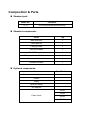
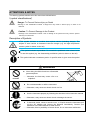
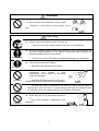
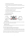
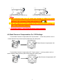
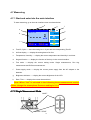
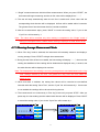
CAPTURE HOOD
MODEL 6710 version 2
INSTRUCTION MANUAL
Be sure to read this manual thoroughly before using the instrument.
Fully understand and pay attention to each caution mentioned.
Please keep this manual as a service reference.
01003
1 5 .08
Thank you for your purchasing a KANOMAX instrument. This is a
precision instrument, please read this instruction manual
carefully before using the instrument and pay attention to all the
cautions under the instructions.
Composition & Parts
Standard part:
Model No.
Functions
6710
Air quantity/temperature/humidity
Standard components:
Items
Qty
Main structure
1
User Manual
1
Carrying Case
1
Instrument Base
1
2ft×2ft Fabric hood
1
Frame poles for 2ft×2ft hood
4
Communication cable
1
Software Installer
1
Optional components:
Items
Specifications
Frame poles for other hood sizes
Printer
Cable
Up-down Stand
AC adapter
2ft×4ft
Fabric hood
1ft×4ft
3ft×2ft
3ft×3ft
ATTENTIONS & NOTES
The warning symbols mentioned in this manual are defined below:
〔symbol classifications〕
Danger: To Prevent Serious Injury or Death
Warnings in this classification indicate a danger that may result in serious injury or death if not
observed.
Caution: To Prevent Damage to the Product
Warnings in this classification indicate a risk of damage to the product that may void the product
warranty if not observed.
Description of Symbols
∆This symbol indicates a condition that requires caution (including danger). The
subject of each caution is illustrated inside the triangle (e.g. the high temperature
caution symbol is shown on the left).
This symbol indicates a prohibition. Do not take the prohibited action shown inside
or near this symbol (e.g. the disassembly prohibition symbol is shown on the left).
● This symbol indicates a mandatory action. A specific action is given near the symbol.
WARNING
Never bring the fabric hood into a flammable
gas atmosphere.
Heating
forbidden
…… Otherwise, the heat may cause a fire or a
explosion.
Do not disassemble or refit the instrument.
Disassembly
prohibition
…… Otherwise, it may cause an electric shock or a fire.
Use the instrument properly by following the directions in this instruction manual.
Using properly
…… Otherwise, it may cause an electric shock or damage the sensor.
If abnormal smells, noises or smoke occur, or if liquid enters the instrument, pull
out the AC adapter and remove the batteries immediately. Contact your
distributor or the manufacturer for after service.
…… Otherwise, there is possibility of electric shock, fire or instrument malfunction.
i
DANGER
Do not exposure the instrument to rain or water.
Forbidden
…… Otherwise, it may cause an electric shock, fire or
injury.
CAUTION
Always unplug the instrument when it is not in use.
…… Failure to do so may cause an electric shock, fire or circuit damage.
Remove the batteries when storing the instrument for a long period of time. Do
not leave drained batteries in the battery compartment and exchange the
batteries promptly when they are drained.
Using properly
…… Failure to do so may cause battery leakage and damage to the instrument.
Only use the provided AC adapter.
Using properly
……Otherwise it may damage the instrument.
Do not use or leave the instrument in a high
temperature,
high
humidity
or
dusty
environment. Do not leave the instrument
under direct sunlight.
Forbidden
……Otherwise, the instrument may not function
properly or the inside components may be damaged.
Do not wipe the instrument with a volatile solvent.
……The body may deform or deteriorate. Use a soft dry cloth to remove stains. If
stains persist, soak the cloth in a neutral detergent and wipe the instrument with
the soft cloth. Never use volatile solvents such as thinner or benzene.
Forbidden
Never drop the unit or place heavy objects on
it.
… It may cause damage or malfunction to the
instrument.
Forbidden
ii
CONTENTS
1.Introduction ...................................................................................................................................... 1
1.1 Product features ..................................................................................................................... 1
2. Capture Hood Structure................................................................................................................... 2
2.1 Instrument Base ..................................................................................................................... 2
2.2 Main structure ......................................................................................................................... 3
2.3 Fabric Hood ............................................................................................................................ 3
3. Installation and Assembling ............................................................................................................ 3
3.1 Capture Hood Installation ..................................................................................................... 3
3.2 Assembling the Frame (detail) ............................................................................................. 4
3.3 Installing the Portable Handle .............................................................................................. 4
3.4 Installing the Main structure.................................................................................................. 5
4. Operation directions ......................................................................................................................... 5
4.1 Communication and Supplying Power with the AC Adapter ............................................ 5
4.2 Supplying Power with Batteries ........................................................................................... 6
4.3 ON/OFF ................................................................................................................................... 7
4.4 Keypad Operation .................................................................................................................. 7
4.5 Incline Adjustment Settings of the Instrument ................................................................... 8
4.6 Back Pressure Compensation On / Off Settings ............................................................... 9
4.7 Measuring.............................................................................................................................. 10
4.7.1 Start and enter into the main interface................................................................... 10
4.7.2 Single Measurement Mode ..................................................................................... 10
4.7.3 Running Average Measurement Mode .................................................................. 11
4.7.4 Back Pressure Compensation Measurement Mode ............................................ 12
5. Display Menu settings ................................................................................................................... 12
5.1 Test Settings ......................................................................................................................... 13
5.1.1 Test ID setting ............................................................................................................ 14
5.1.2 Test Mode settings .................................................................................................... 15
1
5.1.3 Set Units of Measure for Airflow, Temperature and Atmos ................................. 16
5.1.4 Actual flow, Standard flow settings ......................................................................... 17
5.2 General Settings................................................................................................................... 18
5.3 Data processing settings..................................................................................................... 19
5.4 Communication settings ...................................................................................................... 20
5.5 Print Settings......................................................................................................................... 21
6.Main Specifications ......................................................................................................................... 23
7. Common Trouble Shooting ........................................................................................................... 24
8. Warranty and After Service ............................................................................................................... 25
8.1 Warranty ................................................................................................................................ 25
8.2 After Service.......................................................................................................................... 26
2
1.
.Introduction
The model 6710 is used to measure the air flow at the supply and the exhaust points of an
HVAC system. There are several interchangeable hoods of various sizes so it’s easy to find one
that will match the size of the supply and exhaust points of any HVAC system.
The standard size hood is 2ft×2ft (610mm×610mm). Four additional sizes are also available
as options:
2ft×4ft (610mm×1220mm).
1ft×4ft (305mm×1220mm).
2ft×3ft (610mm×915mm).
3ft×3ft (915mm×915mm).
The capture hood is designed to fit tightly over the air port to eliminate any leakage which
could affect the accuracy of a measurement. Users can see the air port through the clear windows
at the top of the capture hood ensuring it is lined up correctly. Fiberglass poles support the fabric
hood.
A velocity matrix is fixed on the base and airflow is tested through sixteen measuring points on
the cross sections of the matrix. The sensor will measure airflow and correct for air pressure and
temperature ensuring an accurate reading every time.
1.1 Product features
Measure air flow, temperature and humidity at the same time
Two kinds of tests are available for supply flow and exhaust flow
Wide test range: 40~4300 m3 /h
Large Storage capacity: 3000 records
3.5 inch color LCD
LCD tilts up to 30°for easy viewing
Back pressure compensation
Automatic air pressure and temperature correction
Light weight, compact configuration for easy transportation
1
2. Capture Hood Structure
The capture hood consists of a fabric hood, main structure and an instrument base. The structural
drawing is below:
Fabric hood
Instrument base
Main structure
2.1 Instrument Base
1) The exterior structure of the base as below: 2)The internal structure of the base as below:
Portable handle
Back pressure on/off
Back pressure plate
Base button
Measurement
matrix
Main structure
Test handle
3)Matrix
There are sixteen measuring points for testing air flow.
Measuring point for air flow
2
Frame poles
2.2 Main structure
Cover lock
Keypad
Display LCD
Battery Compartment
Cover
Socket
for
communicatio
Side view
Back
Front view
POWER
2.3 Fabric Hood
The fabric hood kit consists of a frame, and a fabric hood with four windows as shown below:
Window
Frame
Fabric hood
3. Installation and Assembling
3.1 Capture Hood Installation
1)Assemble the fabric hood and the frame as shown below:
④
③
③
①
②
Use the angled corners ① and
the stitching ② as a guide to
ensure the hood is straight. If
the fabric hood is twisted it will
not assemble correctly.
Insert a frame pole into the
frame and hook it under the
corner of the hood ③.
3
Continue until all 4
corners are supported
by poles ④.
2)The figures below are provided as a reference.
a. Use the mark ① and the stitching as a guide to ensure the hood position.
b. Make sure the hood fully wraps around the base.
①
3.2 Assembling the Frame (detail)
Insert one end of a support pole into its pole mount in the base as in figure ① and the other
end into the frame corner as in figure ②. For the positions of the remaining 3 poles refer to figure
③, and repeat the steps as above.
Note:The support poles always cross in an “X” shape when the hood is assembled. To
remove the poles, simply reverse the steps.
①
②
③
3.3 Installing the Portable Handle
To install the handle line it up with the mounting hole as shown in step ① and ② below. Step
③ shows the handle installed.
①
②
③
4
Note:The support poles and the portable handle should be disassembled before
packing the capture hood in the carrying case to avoid damaging the case.
3.4 Installing the Main structure
To install the Main structure ①, set the bottom of the panel in the holder on the unit base ②
and gently push the top of the panel backwards ③ until it locks into place. To remove it, simply
reverse the procedure.
③
②
①
4. Operation directions
4.1 Communication and Supplying Power with the AC Adapter
Connect the main structure to a PC (refer to figure ①).
① The main structure is connected to a PC.
To power the instrument with the optional AC adapter, refer to figures ② and ③. When the AC
adapter is connected and batteries are installed, power will be supplied from the AC adapter.
The specification of the AC adapter is: I/P: AC 110-240V 50/60 HZ
O/P: DC 5V/ 2A
②The AC adapter supplies power for the main structure. ③The AC adapter also supplies power for the
Capture hood.
structure.
5
4.2 Supplying Power with Batteries
4 AA-size batteries can be used for a power supply.
Press the compartment cover lock (refer to figure ①), and then slide the cover off to open
the battery compartment.
Put 4 AA-size batteries in and make certain the batteries are correctly oriented.
New alkaline battery or rechargeable Ni-MH battery can be used. Never mix battery types,
or battery leakage or damage to the instrument may occur.
Replace the compartment cover (refer to figure ②). The compartment cover will be
automatically locked.
②
①
When power is supplied with batteries, the current charge value will be displayed on the
upper of the LCD. When the batteries run out of power, the instrument will turn off.
Turn off
1. You can’t begin a new test.
2. You can’t use the incline adjustment settings of the instrument.
3. The test may stop if the battery is low during testing.
4. The adjustment settings of the instrument may stop when the battery is
low during adjustment.
Note:
1. Don't use a full_power battery with low power batteries.
2. It is recommended you change batteries when the power shows low.
6
4.3 ON/OFF
1. Getting started
The LCD is displayed below for reference:
(1)Press【POWER】for a while.
(2)Then you enter into the main interface as shown in the left
figure.
2. Shut down
Press and hold 【POWER】for more than 2 seconds in any mode, and the instrument will turn
off automatically.
4.4 Keypad Operation
Keypad operations include the keypad on the control panel as well as the switches on the
base.
The keypad on the control panel is shown below. When a keypad turns gray in the illustration
on the screen, that particular function is invalid.
MOVE/ADJ/SAVE
SET/MENU/OK
ESC/START/STOP/BACK/EXIT
MOVE/ADJ
MOVE: Change an option on the current mode.
ADJ: Change the current value.
7
SAVE: Save the current test results.
SET: Store changes or enter into the selected option’s next level interface.
MENU: On the main screen holding this down for 2 seconds will enter into the main
“MENU”.
OK: Pressing for 2 seconds will save the date or time in the “General Settings”,
Pressing for 2 seconds will delete saved data in the “Record Processing”.
START: Begin a measurement in main menu.
STOP: Stop a measurement in main menu.
BACK: Cancel or end an operation or return to the previous screen.
EXIT: Return to the main menu.
ESC: Stop printing when printing.
Left / right switches on the base
Left switch
Right switch
Left switch on base
Press it once quickly to start or stop a measurement. Press and hold it in for at least 3
seconds to tilt the control panel and LCD screen downward.
Right switch on base
Press it once quickly to save the current data. Press and hold it in for at least 3 seconds to tilt
the control panel and LCD screen upward.
4.5 Incline Adjustment Settings of the Instrument
Start up the instrument and lift the capture hood to the approximate height you will be working
at. Press and hold the left button on the base to tilt the panel downward, or press and hold the right
switch to tilt it up. The buttons must be held down for a minimum of 3 seconds before the panel will
begin to tilt. While the panel is moving, you will hear an audible buzzing.
8
Right switch makes the panel tilt up.
Left switch makes the panel tilt down.
Note:
1. The instrument may turn off, when you attempt to adjust the incline
settings of the instrument if the battery display is at
.
2. You can’t adjust the incline settings of the instrument when testing or if
you’re not in the main interface.
3. To conserve power,avoid tilting the screen unless necessary.
4.6 Back Pressure Compensation On / Off Settings
Turn the Back Pressure Compensation ON: Flip the switch ① to the down position until it is
locked. Make the back pressure plate parallel with the matrix plane.
Back Pressure Compensation ON
①
①
Turn the Back Pressure Compensation OFF: Flip the switch ① to the up position until it is
locked. Make the back pressure plate vertical against the matrix plane.
Back Pressure Compensation OFF
①
9
4.7 Measuring
4.7.1 Start and enter into the main interface
To start measuring, go to the main interface menu as shown below:
h
a
b
g
f
2012 / 06 / 01 13 : 10 : 10
Cycle : 050 Test Mode:
Test ID : 13
e
Single
----
m³/h
SAVE
d
START
c
25.4
℃
53.4
%RH
MENU
a. Test ID, Cycle——save the testing No. in Cycle and the corresponding Test ID.
b. Air flow display ——display the testing data of air flow.
c. Temperature, Humidity ——display the current temperature and humidity in real time.
d. Keypad function ——display the function of the keys in the current interface.
e. Test mode ——display the current testing mode: Single measurement, Run Avg
measurement and B.Press measurement.
f. Power supply mode ——display the current power supply from the AC adapter or the
batteries.
g. Brightness indicator ——display the current brightness of the LCD.
h. Date, Time ——display the current date and time.
Note: When “Act” is selected in the following three measurement modes,
please change the atmosphere Pressure setting in 5.1.4.
4.7.2 Single Measurement Mode
“SAVE”
“START”/”STOP”
10
1)“Single” measurements are individual flow measurements. When you press “START”, the
instrument will begin measuring and the air flow value will be displayed as “- - - -”.
2)The test will stop automatically when the air flow is stable and a flow value with the
corresponding wind direction will be displayed. Air flow will be stable within 8 seconds.
The greater the air flow the shorter the time needed to stabilize.
3)After the measurement stops, press “SAVE” to record the testing value, if you do the
“Cycle” No. will increase by 1.
Note:The value will be recorded only when testing is completed in the “Single” mode. If
testing is interrupted before a stable airflow reading is displayed no data will be saved.
4.7.3 Running Average Measurement Mode
1)When “Run Avg” mode is selected, the instrument will constantly measure and display a
running average. Press “START” to begin the measurement.
2)During the test if the air flow is not stable, the flow reading will display “- - - -”, then once the
reading has stabilized a flow reading will be obtained and displayed every 1 second, and
the wind direction will be displayed in real time.
Note: The displayed air flow reading is a running average that is calculated based on the “Avg
Time” settings entered by the user. The greater the “Avg Time” the more stable the
tested air flow.
3)When auto-save is enabled, the testing flow values will be recorded at user-defined
intervals under the setting “Save Time”, and the “Cycle” No. will increase by 1. If auto-save
is not enabled the readings will not be saved during the test.
4)The instrument will run continuously in “Run Avg” mode until you press “STOP”. After you
press stop, the last reading and the related wind direction will be displayed. Press “SAVE”
to record the testing value, if you do the “Cycle” No. will increase by 1.
2012 / 06 / 01 13 : 10 : 10
Test Mode :
Cycle : 050
Test ID : 13
2012 / 06 / 01 13 : 10 : 10
Test Mode :
Cycle : 050
Test ID : 13
Single
----
m³/h
Single
2890
SAVE
m³/h
START
25.4
℃
53.4
%RH
SAVE
START
25.4
MENU
11
℃
53.4
%RH
MENU
4.7.4 Back Pressure Compensation Measurement Mode
When measuring air flow in an environment with a strong wind or turbulent flow, it will produce
resistance for test air flow and system pressure. It is suggested you turn the Back Pressure
Compensation ON when the air flow is more than 1500 m3/h, otherwise you can test without the
Back Pressure Compensation ON.
1) When “B. Press” mode is turned on, press “START” and the measurement will begin.
2) When "Flap Open!" is displayed, close the Back pressure plate and press "START" to
start the measurement.
3) When the measurement stops, the air flow, as measured with Back Pressure
Compensation will be displayed.
4) After the measurement stops, press “SAVE” to save the data and the “Cycle” No. will
increase by 1.
5. Display Menu settings
(1)In the main interface, press
for 2 sec to enter into
“MENU”.
(2)There are 5 option items in “MENU”:
1.
.Test Settings
2.
.General Settings
MENU
1
1.Test
Settings
2. General Settings
MOVE
3.
.Record Processing
3. Record Processing
4. Communication
5. Print
SET
OK
4.
.Communication
5.
.Print
EXIT
12
5.1 Test Settings
MENU
1
1.Test
Settings
2. General Settings
(1)Press
or
to select “Test Settings”, and press
to
MOVE
3. Record Processing
4. Communication
SET
5. Print
OK
EXIT
enter into “Test Settings”. Press
return to the main
interface.
(2) The option items in “Test Settings” are as follows:
1. Test ID
Test Settings
1. Test ID
1
2. Test Mode
Single
3. Unit
4. Act.Std
Std
2. Test Mode
MOVE
3. Unit
SET
OK
4. Act. Std (Actual / Standard air flow setting)
BACK
13
5.1.1 Test ID setting
A Test ID consists of a group of Cycles (or Samples). A Test ID can contain up to 100 Cycles.
The maximum number of Test IDs is 30. Any new Sample will be saved to the current Test ID. You
can change the current Test ID at any time to keep your data organized. Press
to return to the
“MENU” and the settings will not be saved. Refer to the figures as below:
Test Settings
1.
1 Test ID
2. Test Mode
Single
3. Unit
4. Act.Std
MOVE
SET
Std
Under “Test Settings”, press
or
to choose option
item 1 “Test ID”.
OK
BACK
Press
to change the “Test ID” setting.
Press
or
Test ID
1 Select ID
1.
20
2. Add New ID
No
Total ID:
MOVE
to select a menu item.
SET
30
OK
Press
to enter a setting.
BACK
Under option 1, press .
Test ID
1. Select ID
20
2. Add New ID
No
Total ID:
Press
or
to increase or decrease the Test ID No.
ADJ
SET
30
.
Press
for save your changes,or press
to quit.
OK
BACK
Under option 2, press . .
Test ID
1. Select ID
20
2. Add New ID
Total ID:
No
Yes
30
Press
or
change the settings.
Press
to save your changes, or press
MOVE
SET
OK
BACK
14
to quit.
5.1.2 Test Mode settings
This setting is for change the test mode & the settings about the test modes. Refer to the
steps below:
Test Settings
Under “Test Settings”, press
1. Test ID
2 Test Mode
2.
Single
3. Unit
4. Act.Std
MOVE
or
to select 2 “Test
Mode”.
SET
Std
Press
to enter into the “Test Mode” setting.
BACK
Press
to return to “MENU”.
MOVE
Press
or
SET
below.
OK
Test Settings
1. Test ID
2. Test Mode
3. Unit
4. Act.Std
Single
RunAvg
B.Press
OK
Press
to change the selected item as shown
to save or press
to go back without saving.
BACK
. Single
Under option “Single”, press
RunAvg
B. Press
Test Settings
1. Test ID
2 Test Mode
2.
Single
3. Unit
4. Act.Std
MOVE
SET
Std
OK
BACK
Under option “Run Avg”, press
Test Settings
1. Test ID
2. Test Mode
RunAvg
AvgTime:
01
Auto Save:
Off
sec
MOVE
SET
OK
.
When “Run Avg” is selected, “Save Time” and “Auto Save”
must be set.
Press
or
change the “Avg Time” value.
Press
to save or press
Press
or
to quit.
BACK
Test Settings
1. Test ID
2. Test Mode
AvgTime:
RunAvg
01 sec
Auto Save:Off
10
20
30
60
sec
sec
sec
sec
MOVE
below.
SET
OK
Press
to save or press
Off
BACK
Under option “B.Press”, press
.
Test Settings
1. Test ID
2 Test Mode
2.
B.Press
3. Unit
4. Act.Std
Std
to change the selected item as shown
MOVE
SET
OK
BACK
15
10sec
to go back without saving.
20 sec
30sec
60 sec
5.1.3 Set Units of Measure for Airflow, Temperature and Atmos
For available units, refer to the below chart:
Display shows
Available units
Air flow
m³/h, CFM, l/s
Temperature
℃, ℉
Atmos
kPa, inHg
To change the units of measure, follow these steps:
Test Settings
Under “Test Settings”, select the option 3 “Unit”.
1. Test ID
2. Test Mode
3 Unit
3.
4. Act.Std
Single
MOVE
Std
SET
OK
Press
enter to the “Unit” settings or press
to
return to “MENU”.
BACK
Unit
1 Airflow
1.
CFM
2. Temperature
℃
3. Atmos
kPa
MOVE
Press
or
to select option item 1, 2 or 3.
SET
Press
to change the selected item.
OK
BACK
Under option 1, press
Unit
1. Airflow
Press
m3/h
2. Temperature
3. Atmos
.
CFM
l/s
MOVE
or
to change the selected unit as shown
below:
SET
OK
Press
to save or press
3
m /h
BACK
Under option 2, press
CFM
to quit.
l/s
.
Unit
1. Airflow
CFM
2. Temperature
MOVE
Press
or
to change the selected unit as shown
℃
3. Atmos
℉
SET
OK
below:
Press
to save or press
to quit.
BACK
℃
Under option 3, press
Unit
1. Airflow
CFM
2. Temperature
℃
3. Atmos
kPa
inHg
MOVE
or
to change the selected unit as shown
below:
SET
OK
Press
.
Press
℉
BACK
to save and press
Press
to save or press
to quit.
kPa
inHg
16
5.1.4 Actual flow, Standard flow settings
This setting is for selecting Actual air flow [ACT] or Standard air flow [STD].
Test Settings
1. Test ID
2. Test Mode
Single
3. Unit
4. Act.Std
MOVE
SET
Std
Under the “Test Settings”, select option 4 “Act. Std”.
Press
to enter or press
to return to “MENU”.
OK
BACK
Test Settings
1. Test ID
2. Test Mode
Single
3. Unit
4. Act.Std
MOVE
Press
or
to change the settings as shown below.
SET
Act
Std
OK
Press
to save the changes or press
Act
BACK
Under option “Std”, press
to quit.
Std
.
Test Settings
1. Test ID
2. Test Mode
Single
3. Unit
4. Act.Std
MOVE
SET
Std
OK
BACK
Under option “Act”, press
.
Test Settings
1. Test ID
2. Test Mode
Single
3. Unit
4. Act.Std
MOVE
SET
When “Act” is selected, “Atmos” must be set.
Press
or
to change the Atmos.
Act
Atmos: 101.
101.32 kPa
Confirm the atmos!
OK
Press
to save the changes or press
BACK
17
to quit.
5.2 General Settings
Under “MENU”, select option 2 “General Settings”.
MENU
1.Test Settings
2 General Settings
2.
Press
MOVE
to enter “General Settings” or press
to
3. Record Processing
4. Communication
SET
5. Print
return to the main interface.
OK
EXIT
The settings includes: Date, Time, Backlight and Auto
General Settings
11. Date
2012 / 06 / 01
2. Time
13 : 10 : 10
3. Backlight
High
4. Auto Shut
Off
MOVE
Shut.
SET
OK
BACK
Under option 1, press
.
General Settings
1. Date
12 / 06 / 01
2012
2. Time
13 : 10 : 10
3. Backlight
High
4. Auto Shut
Off
Press
SET
OK
BACK
Press
or
Press
for 2 seconds to save the changes or press
to
Under option 2, press
General Settings
1. Date
2012 / 06 / 01
13 : 10 : 10
2. Time
3. Backlight
High
4. Auto Shut
Off
to select an option as below.
ADJ
ADJ
to quit.
to change the selected value.
Year
Month
Day
.
Press
to select an option as below.
Press
or
to change the selected value.
SET
Press
for 2 seconds to save the changes or press
Hour
Minute
Second
to to quit.
OK
BACK
Under option 3, press
.
General Settings
1. Date
2012 / 06 / 01
2. Time
13 : 10 : 10
3. Backlight
4. Auto Shut
Press
MOVE
Low
Normal
or
to change the backlight setting as
below.
SET
High
OK
Press
to save or press
to quit.
BACK
Under option 4, press
.
High
Normal
General Settings
1. Date
2012 / 06 / 01
2. Time
13 : 10 : 10
3. Backlight
4. Auto Shut
MOVE
Low
Press
or
to select an option as below.
Press
to save your changes or press
High
Off
10min
20min
30min
60min
SET
to quit.
OK
BACK
10min
20min
18
30min
60min
Off
5.3 Data processing settings
MENU
1.Test Settings
2. General Settings
Under “MENU” select option 3 “Record Processing”.
MOVE
33. Record Processing
4. Communication
5. Print
SET
Press
OK
to
to select “Record Processing”. Press
return to the main interface.
EXIT
Record Processing
11.Display
MOVE
2. Delete
SET
Press
or
to select option 1 or 2.
Press
to select a setting to change, or press
to
OK
quit.
BACK
Under option 1, press
Test ID: 01
Max:
Total:30
0
0
0
Min:
Avg:
Total:100
Cycle: 001
Flow:
T:
H:
Time:
The “±” means wind direction of air flow in “Display”.
m3/h
m3/h
m3/h
0
m3/h
25.4
℃
53.4
%RH
2012/06/01
13:15:08
.
ADJ
Press
to select an ID or Cycle No. as below.
Press
or
Press
to quit.
SET
OK
BACK
Under option 2, press
ID
.
to set an ID or Cycle No.
Cycle
Detele
11. Delete All
2. Delete IDs
No
Select ID:
: 05
3. Delete Cycles
No
Select ID :12
Select Cycle:
:000
MOVE
The settings in “Delete” includes: Delete All, Delete IDs,
SET
No
OK
Delete Cycles.
BACK
19
Under option 1, press
Detele
No
Yes
No
1. Delete All
2. Delete IDs
Select ID:
: 05
3. Delete Cycles
Press
No
or
to select option item as below.
ADJ
Press
SET
Select ID :12
Select Cycle:
:000
.
OK
t
for 2 seconds to save the changes or press
to quit.
No
Yes
BACK
Under option 2, press
.
Detele
1. Delete All
2. Delete IDs
No
Select ID:
: 05
3. Delete Cycles
No
ADJ
Press
SET
Select ID :12
Select Cycle:
:000
No
or
Press
OK
to select ID No.
to save the changes or press
to quit.
BACK
Detele
No
1. Delete All
2. Delete IDs
Press
ADJ
No
Yes
Select ID:
: 05
3. Delete Cycles
Select ID :12
Select Cycle:
:000
No
or
Press
SET
OK
t
to select option item as below.
for 2 seconds to save the changes or press
to quit.
BACK
No
Under option 3, press
Yes
.
Detele
1. Delete All
2. Delete IDs
Select ID:
: 05
3. Delete Cycles
12
Select ID :12
Select Cycle:
:000
No
No
ADJ
For “Delete Cycles” refer to the operation steps in
SET
No
“Delete IDs”.
OK
BACK
5.4 Communication settings
Before selecting option 4 “Communication”, ensure the instrument is connected to a PC. If
you quit or disconnect the cable, the instrument will return to the waiting screen as shown on the
right below.
Communication
MENU
1.Test Settings
2. General Settings
3. Record Processing
4 Communication
4.
5. Print
MOVE
Confirm the Connection
Waiting …
SET
MOVE
SET
OK
OK
EXIT
BACK
Waiting for communication
20
5.5 Print Settings
Note:Before printing ensure the following:
1. Please select the factory configuration printer and printer cable. For details,
refer to the printer manual <<RD series of mini-printer>>.
2. Baud Rate is set to 19200. The initial value is set to 19200.
MENU
1.Test Setting
2. General Settings
Under “MENU”, select option 5 “Print”.
MOVE
3. Record Processing
4. Communication
5 Print
5.
SET
OK
Press
to select “Print” or press
return to the main
interface.
EXIT
Print
12. Print By IDs
2. Print By Cycles
MOVE
SET
The setting in “Print” includes: Print By IDs, Print By
Cycles.
OK
EXIT
21
Under option 1, press
Print By IDs
ADJ
Start ID:
Stop ID:
Print:
05
No
SET
Total ID:
05
OK
01
.
Press
or
to select the “Start ID” value.
Press
to save or press
Press
or
Press
to save or press
Press
or
to quit.
BACK
Print By IDs
to select the “Stop ID” value.
ADJ
Start ID:
Stop ID:
Print:
05
No
SET
Total ID:
05
OK
01
to quit.
BACK
Print By IDs
Start ID:
Stop ID:
Print:
Total ID:
ADJ
01
05
No
Yes
SET
05
OK
to select option item as below.
to save the changes or press
Press
No
to quit.
Yes
BACK
Under “Yes”, press
.
Print By IDs
ADJ
Start ID:
Stop ID:
Print:
05
No
SET
Total ID:
05
OK
01
Printing...
Press
to stop print.
ESC
Under option 2, press
.
Print By Cycles
Select ID:
Start Cycle:
001
Stop Cycle:
005
Print:
No
Total Cycle:
12
100
ADJ
SET
For “Print By Cycles”, refer to the operation steps in
“Print By IDs”.
OK
BACK
22
6.Main Specifications
Items
Flow range
40~4300 m³/h
Accuracy
Readings ±3%± 8 m³/h(Air Flow >85 m³/h)
Resolution
1 m³/h
Temperature
range
0~60℃
Accuracy
±0.5℃(within 5~40℃±0.3℃)
Resolution
0.1℃
Humidity range
0~100%RH
Accuracy
±3%RH(10~90%RH)
Resolution
0.1%RH
Air Flow
Temperature
6710 version 2
Humidity
Operating Temperature range
0~60℃(no condensing)
Storage Temperature range
-20~70℃(no condensing)
Atmos. Correction
Yes
Back Pressure Compensation
Yes
Data record
3000
Data Transmission
Data Statistics(Max, Min, and Avg); Check and Delete;
Connect with PC(USB) and the Printer
Hood Size
Standard
2ft×2ft (610mm×610mm)
Optional
2ft×4ft (610mm×1220mm), 1ft×4ft (305mm×1220mm), 2ft×3ft
(610mm×915mm), 3ft×3ft (915mm×915mm)
Power Source
AC/DC Power; or Rechargeable batteries for 9 hours
Weight
Approx. 3.5kg
Standard attachment
Instrument Base, 2ft×2ft (610mm×610mm) fabric hood, Frame
poles, User Manual, Communication cable, Software Installer,
Carrying case and Main structure
Optional
Fabric hood:2ft×4ft (610mm×1220mm), 1ft×4ft
(305mm×1220mm), 2ft×3ft (610mm×915mm), 3ft×3ft
(915mm×915mm), Frame Poles, Printer, Cable, Up-down
Stand(max:3m), and AC adapter
23
7. Common Trouble Shooting
Symptom
Possible causes / troubleshooting
Check the positive/negative connections of the batteries.
→Verify the batteries are inserted correctly.
No display
Low battery charge.
→Replace or recharge the batteries.
Low battery charge.
→Replace or recharge the batteries.
Main structure cannot be adjusted
A test is running.
→Stop the test, adjust the incline settings of the instrument
again.
Check the interface.
→Return to the main interface.
“DATA Error” after test in
B. Press mode
Flap closed pressure was less than flap open pressure, or flap
open versus flap closed pressure ratio exceeds allowed limits.
→Test again.
Test data was not saved after
testing
The Cycle is full in the current ID.
→Add a new ID.
The current ID is already a new ID.
→Use the current ID.
A new ID cannot be added
Check the ID No.
→If the ID No is 30, delete some IDs.
Print appears garbled
Baud rate does not match.
→Set Baud again.
Display “Connect Error”
Check the connection between the instrument and the cable.
→Connect the cable again and restart.
Check the connection between the instrument and the cable.
→Check the cable, and connect again.
The test does not begin after
pressing “START”
Low battery charge.
→Replace or recharge the batteries.
The instrument is being adjusted.
→Stop adjusting the instrument.
Check the back pressure plate.
→Close the Back pressure plate.
Check the connection between the instrument and the cable.
Test exception when testing
→Check the cable, and connect again.
Abnormal operation of
solenoid valve when testing
the
Motor movement disorders when
testing
Check the connection between the instrument and the cable.
→Check the cable, and connect again.
Check the connection between the instrument and the cable.
→Check the cable, and connect again.
24
8. Warranty and After Service
8.1 Warranty
The limited warranty set forth below is given by KANOMAX GROUP COMPANIES with
respect to the KANOMAX brand capture hood and other accessories (hereafter referred to as
“PRODUCT”) purchased directly from KANOMAX GROUP COMPANIES or from an authorized
distributor.
Your PRODUCT, when delivered to you in new condition in its original container, is warranted against
defects in materials or workmanship as follows: for a period of one (1) year from the date of original
purchase, defective parts or a defective PRODUCT returned to KANOMAX GROUP COMPANIES, as
applicable, and proven to be defective upon inspection, will be exchanged for a new or comparable rebuilt
parts, or a refurbished PRODUCT as determined by KANOMAX GROUP COMPANIES. Warranty for
such replacements shall not extend the original warranty period of the defective PRODUCT.
This limited warranty covers all defects encountered in normal use of the PRODUCT, and does
not apply in the following cases:
(1) Use of parts or supplies other than the PRODUCT sold by KANOMAX GROUP COMPANIES,
which cause damage to the PRODUCT or cause abnormally frequent service calls or service
problems.
(2) If any PRODUCT has its serial number or date altered or removed.
(3) Loss of damage to the PRODUCT due to abuse, mishandling, alternation, improper packaging by
the owner, accident, natural disaster, electrical current fluctuations, failure to follow operation,
maintenance or environmental instructions prescribed in the PRODUCT's operation manual
provided by KANOMAX GROUP COMPANIES, or service performed by other than
KANOMAX GROUP COMPANIES.
NO IMPLIED WARRANTY, INCLUDING ANY IMPLIED WARRANTY OF MERCHANTABILITY
OR FITNESS FOR A PARTICULAR PURPOSE, APPLIES TO THE PRODUCT AFTER THE
APPLICABLE PERIOD OF THE EXPRESS LIMITED WARRANTY STATED ABOVE, AND NO
OTHER EXPRESS WARRANTY OR GUARANTY, EXCEPT AS MENTIONED ABOVE, GIVEN
BY ANY PERSON OR ENTITY WITH RESPECT TO THE PRODUCT SHALL BIND KANOMAX
GROUP COMPANIES. KANOMAX GROUP COMPANIES SHALL NOT BE LIABLE FOR LOSS
OF STORAGE CHARGES, LOSS OR CORRUPTION OF DATA, OR ANY OTHER SPECIAL,
INCIDENTAL OR CONSEQUENTIAL DAMAGES CAUSED BY THE USE OR MISUSE OF, OR
INABILITY TO USE, THE PRODUCT, REGARDLESS OF THE LEGAL THEORY ON WHICH
THE CLAIM IS BASED, AND EVEN IF KANOMAX GROUP COMPANIES HAS BEEN ADVISED
OF THE POSSIBILITY OF SUCH DAMAGES. IN NO EVENT SHALL RECOVERY OF ANY
KIND AGAINST KANOMAX GROUP COMPANIES BE GREATER IN AMOUNT THAN THE
PURCHASE PRICE OF THE PRODUCT SOLD BY KANOMAX GROUP COMPANIES AND
CAUSING THE ALLEGED DAMAGE. WITHOUT LIMITING THE FOREGOING, THE OWNER
ASSUMES ALL RISK AND LIABILITY FOR LOSS, DAMAGE OF, OR INJURY TO THE OWNER
AND THE OWNER'S PROPERTY AND TO OTHERS AND THEIR PROPERTY ARISING OUT OF
USE OR MISUSE OF, OR INABILITY TO USE, THE PRODUCT NOT CAUSED DIRECTLY BY
THE NEGLIGENCE OF KANOMAX GROUP COMPANIES. THIS LIMITED WARRANTY SHALL
NOT EXTEND TO ANYONE OTHER THAN THE ORIGINAL PURCHASER OF THE PRODUCT,
25
OR THE PERSON FOR WHOM IT WAS PURCHASED AS A GIFT, AND STATES THE
PURCHASER'S EXCLUSIVE REMEDY.
8.2 After Service
When you have a problem with your instrument, please check out the “Common Trouble
Shooting” section first.
If that does not help, please contact your local distributor, or contacts on the last page.
During the warranty period, we will repair at no charge a product that proves to be defective due to
material or workmanship under normal use.
All return shipping charges are the responsibility of the customer.
Repair after warranty expiration:
Upon request, we will repair the instrument at the customer’s expense, if the instrument’s
performance is found to be recoverable by providing the repair.
Replacement parts are available for a minimum period of five (5) years after termination of
production. This storage period of replacement parts is considered as the period during which we
can provide repair service. For further information, please contact your local distributor, or
contacts on the last page.
When making an inquiry, please provide the following
information.
(1) PRODUCT name: Capture Hood
(2) Model Number:
6710 or XXXX
(3) Serial number:
xxxxxx
(4) P/O or Invoice No: xxxxxx
(5) Description of the problem in detail:
(6) Data of Purchase: Day, Month and Year
26
Kanomax Group Companies
Americas, Europe, Mid-East, Africa, Oceania
KANOMAX USA, INC.
219 US Highway. 206, Andover, New Jersey 07821
Tel:
1-800-247-8887(USA) / 1-973-786-6386
FAX:
1-973-786-7586
URL :
www.kanomax-usa.com
E-Mail:
[email protected]
Se Habla Espanol
Japan & Asia
KANOMAX JAPAN, INC.
2-1 Shimizu Suita City, Osaka Japan 565-0805
Tel:
81-6-6877-0183
FAX:
81-6-6879-2080
URL :
www.kanomax.co.jp
E-Mail:
[email protected]
China
Shenyang Kano Scientific Instrument Co., Ltd
#2610,51 Wulihe Street Heping District, Shenyang City, PRC
Tel:
86-24-23845309
FAX:
86-24-23898417
URL :
http://www.kanomax.com.cn/
E-Mail:
[email protected]