1
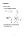
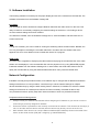
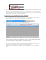
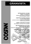
Granvista Plus Series
H.264 2-Megapixel Network Camera
GVP-201 / GVP-201W
User’s Manual
Version: 1.32
Revised Sept, 2012
Contents
Notices ................................................................................................................................................. 2
Introduction .......................................................................................................................................... 3
Installation ............................................................................................................................................ 4
Using the Web UI ............................................................................................................................... 10
1. Live View ............................................................................................................................... 12
2. Video ...................................................................................................................................... 14
General ............................................................................................................................... 14
Advanced ........................................................................................................................... 15
3. Camera ................................................................................................................................... 19
General ............................................................................................................................... 19
Advanced ........................................................................................................................... 21
4. Event ...................................................................................................................................... 22
Event Server ....................................................................................................................... 23
Motion Detection ............................................................................................................... 25
Event Configuration ........................................................................................................... 26
5. Schedule ................................................................................................................................. 30
General ............................................................................................................................... 30
Storage ............................................................................................................................... 30
6. Network.................................................................................................................................. 35
General ............................................................................................................................... 35
Advanced ........................................................................................................................... 36
SMTP (E-Mail) .................................................................................................................. 38
DDNS ................................................................................................................................. 40
Wireless (GVP-201W) ....................................................................................................... 45
7. System .................................................................................................................................... 47
Information......................................................................................................................... 47
User .................................................................................................................................... 48
Date & Time ....................................................................................................................... 49
Server Maintenance............................................................................................................ 49
Log Service ........................................................................................................................ 51
8. Customize............................................................................................................................... 51
9. FAQ ........................................................................................................................................ 53
Check firmware version ..................................................................................................... 53
Restore to Factory Default ................................................................................................. 54
Upgrade device firmware ................................................................................................... 55
Video Streams Specification .............................................................................................. 56
The Angle of View at different resolutions ........................................................................ 57
Appendix I: An example of how to set up users’ own FTP servers ................................................... 58
Appendix II: How to install the VLC program .................................................................................. 67
Appendix III: How to replay the recorded video clips with VLC program ....................................... 69
Appendix IV: Commands for system integrations ............................................................................. 70
1
Notices
This user manual is intended for administrators and users of the GVP-201/GVP-201W Network Camera,
including instructions for using and managing the camera on your network. The use of surveillance devices
may be prohibited by law in your country. It is the user’s responsibility to ensure that the operation of such
devices is legal before installing this unit for its intended use.
Before the Network Camera is installed, all the safety and operating instructions should be carefully read and
followed to avoid damage due to faulty assembly and installation. This also ensures the product is used
properly as intended.
Heed all warnings
Do not drop or strike this equipment
Sensitive electronics inside the camera are vulnerable to excessive strike.
Do not install the equipment near any flames or heat sources
Excessive heat could damage this equipment.
Do not cover cloth or to install this equipment in poorly ventilated places.
Overheating could damage this equipment.
Do not expose this equipment to rain or moisture. Do not touch the power connection with
wet hands
Risk of short circuit, electric shock or fire
Do not damage the power cord or leave it under pressure
Risk of fire or shock circuit
To reduce the risk of electric shock, do not remove the Cover (or Back).
No user-serviceable parts inside. Misusage, improper, and negligence could damage this
equipment. Need to refer servicing to qualified
service personnel.
Do not continue to operate if it appears to be
faulted.
If the unit ceases functioning, contact qualified
service personnel for help.
Any works related to detailed service or repair of
this product should be made by qualified
personnel only.
We strongly recommend to use the metal
mounting stand, and to screw the
bracket/spacer tight for optimal heat
dissipation.
2
Introduction
Both GVP-201 and GVP-201W are of compact and high resolution (1600x1200) Network Cameras
featured with superior H.264-AVC performance and multiple functions. They are perfect for indoor
applications such as factories, retailer stores, residence, restaurants, hotels, schools and pre-schools,
caring centers, etc.
GVP-201’s H.264-AVC video compression has significantly lowered down the requirements for bandwidth
and storage size without compromising image quality.
Motion JPEG and multiple independent video
streaming are also supported for even better flexibility.
The camera offers wired Ethernet connection to the network and optional wireless connectivity
(IEEE802.11b/g) for flexible installations. It includes 7 IR LEDs for illuminating the scene automatically or
when requested by the user. Further functions include two-way audio with integrated high-sensitivity
microphone and audio output, Micro SD card support and digital PTZ (4X) to focus any location you would
like to highlight in the image.
3
Installation
1. Hardware Connection
4
2. Software Installation
The following software is necessary for the proper display and use of the camera from the Web site. The
software will be taken from the Software Package CD.
IP Installer
The IP Installer is used to locate and configure Network Cameras and video servers on the LAN. This
utility is useful for conveniently configuring the network settings of the device, or for finding a device
once the network settings have been modified.
To install the IP Installer, from the Software Package CD UI, select IPInstaller, and then follow the on
screen instructions.
VLC
Though not necessary, this can be used for viewing the streaming without a Web browser. Besides, the
VLC may be helpful in reviewing the recorded video files in the Micro SD card. Please refer to the
appendix II & III for more details on how to install and use the VLC program.
XVID Codec
An H.264 codec is applied for displaying the video stream and playing the recoded AVI files. If the video
stream can’t be displayed, or the recorded AVI files can’t be played on PC by using MPLAYER program,
install this software from the Software Package CD. In other words, this XVID Codec allows users to
replay the recorded files by using the Windows MPLAYER which many users are familiar with.
Network Configuration
IPInstaller is a utility that provides an easier, more efficient way to configure the IP address and network
settings of the devices. It even provides a convenient way to set the network settings for multiple
devices simultaneously by using the batch setting function. Moreover, IP Installer can save the network
settings for all devices as a backup and restore them when necessary. IPInstaller is able to help
non-professional users to quickly setup their network cameras to work in a professional manner.
Preparation before IP Assignment
1.
2.
3.
Always consult your network administrator before assigning an IP address to your server in order to
avoid using a previously assigned IP address.
Ensure the device is powered on and correctly connected to the network. This network can be simply a
hub, PC and the network camera; and the network camera may directly connect to the PC too.
MAC Address: Each device has a unique Ethernet address (MAC address) shown on the label of the
device as the serial number (S/N) with 12 digits (e.g. 000429-XXXXXX).
5
*0004290000
B1
4.
Although the IPInstaller is able to find and configure any Network Cameras in the LAN except those that
are behind a router, it is a good idea to set the host PC to the same subnet. In order to connect to the
Web-based user interface of the camera, the host PC must be in the same subnet. For more information
about subnets, please consult your network administrator.
Using IPInstaller to Assign an IP Address to GVP-201 / GVP-201W
1.
Once IP Installer has been successfully installed on the PC, double click the IP Installer icon on the
desktop, or select it from Start > Programs > IP Installer > Launch IP Installer.
2.
Click the “Device Search” tool bar and search the device in the LAN.
Please note that the firewalls of your Windows or Anti-virus software might block IP Installer from
searching the cameras. In this case you would need to unblock IP Installer software from the firewalls,
or to manually make this IP Installer software an exception to the firewalls.
3.
From the list, select the device with the MAC Address that corresponds to the device which is to be
configured. The MAC Address is identical to the unit’s S/N (Serial Number).
4.
Right-click and select the “Single Device Setting” item to open the Property Page for the selected
device.
6
5.
After filling in the properties, click [Set] button to complete the configuration settings in the remote
device.
7
Example about how to know the user’s PC and network information from command prompt. Simply type in
“ipconfig” in the Command Prompt screen, press Enter, and you will see the related information which
shows you the PC’s IP, Subnet Mask, Default Gateway, etc.
The first three numbers of the network camera’s IP must be same as the first three numbers of the
PC’s IP address. In the above example the PC’s IP address is 192.168.1.6., and we have set the camera’s
IP to be 192.168.1.188. The network camera IP’s first three digits must be the same as the PC IP’s first
three digits, otherwise the screen can not be displayed properly on the WWW browser.
Open the Web-based UI of the Selected camera
1.
2.
3.
4.
To access the Web-based user interface of the selected unit by right-clicking and selecting “Open web”
from the slide-bar.
If the device has been configured correctly, the default Web browser, the Internet Explorer, will open to
the home page of the selected device.
If you find your browser is opened and automatically connected to the camera Home Page, it indicates
that you’ve assigned an IP Address to the unit successfully. Now you can close the IP Installer and start
to use your camera.
Usually the users no longer need to run the IP Installer software again after configuring the cameras
correctly.
8
Verify and Complete the Installation from Your Browser
If not able to get the ActiveX downloaded properly, user must temporarily lower the security settings to
perform a one-time-only installation of the ActiveX component onto the workstation, as described below:
- From the Tools menu, select [Internet Options] -> [Security] -> [Custom Level]
- Set the security level to Low and click [OK].
- Depends on different versions of browser software used, the users may have to set the individual ActiveX
settings from “Disable” to “Prompt” or “Enable” if necessary for completing the ActiveX program
downloads.
- Restore the security level after the ActiveX installation.
9
Using the Web UI
Start your Web browser and enter the URL or IP address in the Address field. The Home page of the
camera is now displayed.
Note: Please do select “Run as administrator” to start the Internet Explorer browser if you are using
Win-7 platform, otherwise you may not have the audio function to run properly.
10
How to make the Mozilla Firefox properly work with the cameras?
Please note that in addition to Microsoft Internet Explorer, other browsers such as Mozilla Firefox, Safari and
Google Chrome are also compatible for viewing the screens from Granvista Plus network cameras. However,
you may not be able to get full two-way audio supports from Firefox, Safari and Google Chrome due to the
WWW browser software’s existing support status on the needed plug-ins. If you want to have camera’s audio
feature with Firefox browser, you would have to install the needed plug-in from VLC.
Similar to Internet Explorer which needs to download the needed ActiveX programs, the Firefox browser will
guide the users to download and install the VLC program for the needed plug-in the first time when it
connects to the network cameras, so that it can work properly.
In the process of installing the VLC program, please be sure to check the “Mozilla plugin” option, so that
Firefox may work properly with the network cameras.
The VLC program is a very handy shareware that the users will find it helpful when they want to replay the
“.mp4” video clips recorded by the cameras. Actually the users may use its streaming function for viewing the
camera’s rea-ltime screen directly too. Please refer to the “Video/Advanced” introduction for more details.
Please note that the example here does not necessarily reflect to the latest version of VLC program.
11
1. Live View
Button
Description
Click for more general/advanced camera settings
Select languages among English, traditional Chinese, simplified
Chinese and Spanish. If you like to add customized interfaces with
other languages, please refer to the “How to add a new language into
the user interface V.1.0.ppt” file in the CD for more details.
Check actual size to view the actual size (resolution) of the image
Image Setting: To adjust the brightness, hue and saturation
Choose among different streams for viewing. Due to bandwidth
constraints the users may want to choose its 2nd video stream which
is of 640x480 or 320x240. This 2nd stream supports digital PTZ
rd
function which users should find it helpful. There is a 3 stream of
fixed 640x480 resolution, and which is for 3G connection only @1fps.
12
Button
Description
Full screen
Listen to the audio input from site. If users are using Vista / Windows 7, please
right-click on the desk shortcut or the main program, select “Run as
administrator” to start the WWW browser, otherwise the audio function may not
work properly.
Talk function. An external speaker need to connect to its audio jack for audio
output
Record instant live video
Snapshot the image
Further configurations and options; a prominent button in between is used to expand the further operations.
Click on the indicated prominent, and more operational options shows up.
13
2. Video
General
Video General Setting: Check each box to enable needed streams (max 3, including the 3rd one for 3G
mobile phone) for live viewing
Note: Digital PTZ is only available with stream 2. Please select the required video streams only, so that the
system can be running at best performance. Stream #3 is not shown, because it is for G3 mobile phone
connection only. Stream #3 is not shown, because it is for 3G mobile phone connection only. It is transmitting
at 1 frame per second / 640x480.
OSD Setting: Enable OSD (Over-Screen-Display) to display camera name or date/time on the image, the
camera name must be a continual string, for instance “LivingRoom”. This OSD setting may be set from the
NVR too if any Granvista Plus series NVR has linked to this network camera.
14
Advanced
15
RTSP Path The RTSP(Real Time Streaming Protocol)Path is the stream ID used for RTSP client’s streaming connection,
such as VLC player or Blue Iris program. The default values are v00 and v01 for the two streams respectively.
The string can be any combination of number or capital/small letters. It can not be empty however. By way of
defining the RTSP path names, the system administrator may control whoever may connect to whichever
cameras inside the network.
Following is a setting example of RTSP steaming by using VLC program. (The users may access this setup
screen from VLC program’s Media/Streaming…/Network).
Note: the “port number” of 556 in the example is its RTSP port number which the user has defined for this
camera (default value is 554). This port number must be routed in the network router properly if the user
likes to receive the video streaming from the web. In other words, if the user likes to use the external web
address of rtsp://219.86.240.234:556/v00 in stead of the LAN address of rtsp://192.168.1.99:556/v00.
The above is a setup screen example of an Internet broadband router. In this example the port 91 is for
WWW, and the port 556 is for RTSP. These two port numbers must be same as what configured in the
camera’s Network/Advanced settings.
16
Note: the users may right-click and choose VLC program’s “Full Screen” mode too.
Resolution The resolution here describes an image size counted by width and height, e.g. 640x480, referring to pixel
resolution. The 1st stream can be set from more options of resolution; 1600x1200 (2 megapixels),
1280x720(HD), 800x600(SVGA), 640x480(VGA), 320x240(QVGA). While Stream2 has the options of VGA
and QVGA, stream3 is in a fixed resolution, the VGA. The users need to decide which resolution and frame
rate options to be selected according to the requirements and practical constraints from the bandwidth and
storage available.
Video Mode This option allows the selection of two bit-rate modes, the Constant Bit Rate (CBR) or Variable Bit Rate (VBR).
CBR refers to the setting of a fixed Target Bit Rate (configuration in the range of 64Kbps to 6Mbps) that
would apply in the case of limited bandwidth or/and storage requirement. While CBR concerns a fixed data
rate transmitting, the video quality setting is of high priority for VBR mode selected. VBR therefore is
configured with the Quality Level (Standard, Good, Best). In general, CBR predicts the provided condition; if
image activity requires higher bit rates than configured, the frame rate and quality would be affected as not
likely to increase bandwidth (bit rate). In spite of the required recording storage estimation, VBR is by way of
compensation that adjustable bit rate fits the actual image activity.
Image Format H.264 and MJPEG are available for image format selection. The term, “image format”, is referring to
compression / encoding technique. The selection of image format decides the performance of bandwidth and
17
storage requirement. In the request of same video quality, H.264 contributes to less bandwidth and storage
requirement, which is much more efficient than MJPEG. Therefore it is usually a better selection to select
H.264 format if there is no particular reason for MJPEG.
GOP In MJPEG/H.264 video coding, GOP (group of pictures) describes how the different types of frames are
arranged. The frame types implemented here are I-frame (full image information) and P-frame
(motion-compensated difference information). This setting configures the GOP length which is the number of
frames before next I-frame appears. Having more I-frames usually increases the stream size, and therefore
more bandwidth and storage are required.
Frame Rates The Frame Rates defines the number of frames that will be displayed per second. The frame rate setting can
affect the target bit rate (bandwidth requirement) and storage requirement.
The pre-configured frame rates can usually be fulfilled inside the local areas networks. However, it may not
be able to be fulfilled for remote access, or if the network traffic is heavily loaded. For instance, if the camera
has been configured to be 15 fps, the user most probably may see full 15 fps speed inside the LAN; however,
the user might only be able to see 1-2 fps of video stream if he/she wants to connect from Internet remotely.
The codes of the camera have been programmed this way that the camera will have to drop the P-frames
inside its buffer on every connection session in case these queued P-frames still can not be sent out to the
clients-side timely due to network traffic condition, in case the data buffer is close to be over-flown, so that the
user can still see a lower-frame-rate, but still smooth enough video stream when network bandwidth is not
sufficient.
Note:
While multiple streaming is possible, each stream has its limitation and dependency to other stream. See
“Video Stream Specification”.
18
3. Camera
General
19
Camera General Setting:
Brightness: the luminance of image view
Hue: refer to pure a pure color, or described by its name, such as red, green or blue.
Saturation: intensity of a specific color
The 3 correlates are referring image appearance in terms of color/vision. These are adjustable from this page.
Rotation 180 degree: rotate the image, so it looks up-side down. This can be applied when camera unit must
be mounted up-side down.
Image Mirror Horizontal: to select for horizontally flipped image if necessary.
Audio Setting:
Enable this option, so the video stream will be transferring together with the audio data. There are two types
of formats of AAC and G711. AAC takes less bandwidth, while its quality is fairly good already, but the users
may still want to choose G711 if they want even better audio quality, and if there is no bandwidth and storage
size concern.
AAC format must be selected if the users want audio to be recorded together with the video in Schedule or
snapped web recording.
In case there is a Granvista Plus series NVR (network video recorder) available in the network for recording,
the NVR will set G711 as its audio default.
Web Record/Snapshot Setting:
Web Record / Snapshot: define the locations where snapshot images and video clips will be stored. The file
name is referring to the prefix of the file name of each snapshot image or video clip generated. These two
settings’ are saved in the Web Browser such as Internet Explorer, thus the settings will be reset if you reset
the Web Browser software. Users may find it an easy cure to set it up in Windows’s Safe Mode when they
encounter problem with Vista platform which is stricter and more complicated in security settings than other
platforms.
As to the “Web Recording Setting”, if you have chosen D:\TEMP as the path and “video” as the file name
prefix then the generated files will be saved into the D:\TEMP directory, and their file names will be in the
format of “video” plus time tags, such as “video_20110102_121313_770”. The “Web Snapshot Image Setting”
is configured in the same way.
If users are using Vista / Windows 7, please right-click on the desk shortcut or the main program, select “Run as
administrator” to start the WWW browser, otherwise Windows may not allow you to configure properly.
Default:
Set [camera general setting] and [audio setting] back to default
Note: As mentioned above, this Default command will not change the configuration of [Web Record Setting]
and [web Snapshot Image Setting]
Save:
Save the changes which have been made
20
Advanced
White balance: Adjustment to compensate for different environments in terms of light source.
Exposure: Anti-flicker setting for image sensor to fit the frequency of light (power) source. For instance, the
power frequency is 50Hz for most European countries, while 60Hz is typically for US. This setting is therefore
regionally different. Note: Default setting is 50Hz
Max Exposure Time: Referring to the shutter speed. To set to slower shutter speed such as 1/15 second is
one alternative to improve image in case of dark environment with IR illumination.
Max Gain Control: The maximum amplification factor for the incoming light. Similar to the photographic
theories, in case of environment of dim light, increase it for optimal result if necessary. On the contrary, turn it
down for environments of stronger light if necessary. Usually the users may leave it at max setting without the
need to change for best results.
Illuminator LEDs: The default is automatically switched according to site illumination. LED will turn on when
there is light deficiency.
Status LED: Turn on/off the camera status LED. You may want to purposely turn it off if you do not want
people to tell whether it is operational or not.
Light Sensor Day / Night Threshold: Adjustment for fine-tuning how dark to turn on the IR LEDs. The lower
the setting, the darker it has to be to turn on the LEDs.
Back Light Compensation: Option for automatically making compensation for back light.
21
4. Event
Event handling describes the configurations of events and the corresponding actions. To have an insight into
this function, a common example can be storing the captured images or video clips to Micro SD card (up to
32GB in storage size) , a remote disk in LAN (SAMBA), FTP server or Email account (images only), when
there is an Event (motion or periodic triggering).
22
Event Server
The “Event Server List” lists the configured server(s) that will act as a remote storage or a destination for
handling the triggered events. Up to 10 FTP servers can be added in the list.
Click on the [Add FTP] to expand FTP server setting
FTP Server:
Name: Give a name for the FTP server.
Network Address: Input the network address of the FTP server, which can be located in LAN or
external web, for instance “192.168.1.100” or “219.86.240.234” respectively. Please note that such
WEB IP such as “219.86.240.234” can be applicable only when the network is connected to
Internet, and it is properly configured in the broadband router.
Upload Path: Choose the desired upload path for events. If not specifically defined, it will be the
default folder configured in the FTP system.
Port: Input the port number of the FTP server, typically 21.
Remarks: FTP is quite a convenient web application, and it is quite easy to use. Attached below is
an example of FTP screen indicates that a Network Camera keeps on talking to the FTP server. In
this example the FTP server address can be set as either 192.168.1.3 (LAN) or 219.86.240.234
(WEB) from near end.
23
Login Information:
Username / Password: Input the username and password of the FTP
Click [Remove] to delete selected event servers
Please refer to Appendix-I for more information on FPT applications.
24
Motion Detection
A snapshot image shows the whole view of the camera covered. To select a motion detection area, click
directly on the image, and then change the size and position by dragging and drawing. Up to 10 motion areas
(configurations) can be added in the list. Each detection area can be set with its own sensitivity value.
25
Event Configuration
The Event Configuration is to assign the actions responding to the specified events (Trigger Conditions).
The table lists the configured events. Click on “Add…” or choose an event from the list to extend the panel for
detail configurations. “Remove” is to delete a selected event.
A total of up to 10 event settings with different combinations of motion detections, or automatic triggering
based on every period of time can be configured into the system.
Note: Please refer to the following setup screen to make sure the Micro SD card is available before you are
able to record the Event data into the Micro SD card.
26
Trigger types (conditions)
Motion Detection: The configured detection area(s) for motion events.
27
When triggering action activated
Store image to FTP (Remote), Email or SD card (Local)
Time Lapse of Events
Events may come frequently, for instance, a moving object may keep triggering in a detection area, and false
alarms may therefore occur. The “minimum time between triggers” setting is then for this case. System
waits for the given time before the next trigger taken.
Period: To be triggered every preset period of time. The time lapse of periodic triggering can be one minute
up to 23:59:59.
28
Note: there is another manual trigger functionality available from clicking trigger button embedded on the web
main page.
H.264 mode triggered recording:
Not only for triggering images of jpg format, the camera allows users to trigger video clips of H.264 format
with pre-defined time lengths of 15, 30 45 or 60 seconds.
This H264 video clip triggering function provides another option in addition to Schedule recording function at
pre-defined data size.
Please note that the video clips generated may be flexibly sent to SD card, FTP or Email, but due to actual
constraints from the availability of the needed network resources and its bandwidth, the FTP and Email
options may not work as well as expected. The users have to make the best judgment not to impose
unnecessary loading to its CPU and the network loading for optimal performance.
29
5. Schedule
GVP-201/GVP-201W series models are equipped with a card slot for Micro-SD/SDHC storage. This storage
is applied for local video and image recording. The recording function can be launched according to
scheduled time frames. The SD card also records the JPEG images responding to an event.
The size of Micro SD card can be up to 32GB, preferably be at least Class-4 or even faster grades.
General
Define the day (specified by days of a week) and time (specified by each single hour) for that the video, or
even the audio, will be recorded during the scheduled period. User can select which video stream should be
recorded, and the size of each sliced file. When the check box is ticked, recording process starts at the
scheduled hours (red blocks). The user may select on “ALL”, or the raw and column notations for a quicker
selection.
Storage
Display the storage information, includes disk size info, type and status. The warning message (red text)
shows when recording is in process; SD card should not be removed during the recording process.
30
The “Browse” button allows viewing the list of recorded files. The web page will then be redirected to the root
path of the SD storage (if one is inserted). The list includes couple of folders, the event_images which
contains all the still images captured by any event trigger, and folders specified by date where the recorded
video files are located.
The recorded video files are named in date_time format, and the extension file name is “.mp4”. The recorded
files can be re-played with VLC or other application programs. Please note that AAC audio format needs to be
selected if audio needs to be recorded into the files as well, and the recoded files will be in MP4 format. If the
users have selected G711 as the audio format, audio won’t be recoded into the files to save the file spaces,
and the recorded files will have the extension file name of H264. The Granvista Plus series NVRs all have
much storage spaces which are able to record superior audio into the files thus the NVR will set G711 audio
format as default.
The files generated from the recording process are handled on “first-in-first-out” basis. In other words, the
oldest folders/files will be deleted when there is not enough space for the new data.
31
The recorded files may also be recorded into the remote-disk in LAN (Samba) instead of SD card. Please
refer to following setup screens with setup tips for more details.
32
Please note that the remote disk to be utilized in the LAN PC needs to be shared properly
beforehand.
Depends on different resolutions, frame rate, data formats and time frames are configured, a Micro SD of
32GB is able to handle several days of data storage already, and the storage space from Remote-Disk has
provided another alternative too. Apparently the camera’s recording functionality with Micro SD card or
Remote-Disk is able to satisfy users’ basic data storage requirements already.
Besides, the free-bundled GVD software is also a good option to use for video recording purpose under
minimized budget, if the users happen to have spare PCs with relevant hardware compatibility (the PC’s
screen resolution and CPU performance must be above a decent level to make this NVR software running at
optimal performance).
In addition, the users may also take advantages of our Linux-based Granvista Plus NVR for even more
advanced and professional applications. Up to 64 connections, or even more, are able to be built into the
Granvista Plus series NVRs. Please refer to our web site, or contact us for more details. Attached below is a
sample of our SOHO model NVR which may support up to 6 connections.
33
34
6. Network
Network Camera acts as one of the network devices. It therefore allows its “IP” to be assigned, so certain
network functionalities can be implementable within this device. This section describes these configurations.
Fundamentally, for instance, the IP assignment of the device can be done via DHCP server, manually fixed
IP option or PPPoE to obtain IP from service provider.
General
Device IP configuration, includes DHCP, Static IP setting and PPPoE. “Enable ARP/Ping” enable device to
accept ARP or ping packets from the network. Disable this option may provide extra security from intentional
ping.
35
Advanced
Enable or configure other network functions.
NTP: Configure a NTP (Network Time Protocol) server, so that the device system date and time can be
synchronized with a specified Time Server. This configuration is provided for one of the potions of system
date/time adjustment. If the camera is located in an isolated LAN, in other words it does not have access to
web, the user may set the IP of the PC in LAN as its NTP setting, so that the camera’s time will be
synchronized with the PC.
HTTP: set the HTTP port that will be applied for Web UI access. The default port number of HTTP is “80”, but
it can be of other figures.
RTSP: set the RTSP (Video) port for video data transmission. The default port number of RTSP is “554”, but it
can be of other figures.
36
Bonjour: Enable Bonjour service, so that the device can be discovered with “Bonjour” service applied.
UPnP: Enable UPnP, so that the device can be discovered in an UPnP Compliant Network.
NAT Traversal: Enable NAT traversal, so that client from Internet can have access to the devices behind the
Router. If user would like to access the Network Camera from Web externally, be sure to also include the
RTSP port by duplicating the same IP.
In the following example this Network Camera’s LAN IP is of 192.168.1.2., thus the user should type in the full
address of http://192.168.1.2:80 (as port 80 is WWW’s default port number thus “:80” can be omitted) in the
address field of Internet Explorer to access this network camera. If the user wants to access it from web
externally, he would have to properly setup its HTTP port (in this case “80”, or other port number), and the
RTSP port (in this case “554”, or other port number)) in the NAT setting of the router beforehand, and then he
may access it with the web address (in this example it is http://219.86.240.234:80 to access it from anywhere
of the world via Internet) if the router has connected to Internet.
Note: with UPnP enabled, the IP Sharing device (Router) capable of UPnP function will automatically be
noticed with the device’s NAT port.
37
SMTP (E-Mail)
Configure an email host in the device that will send email on behalf of the configured email account in a
circumstance like sending an email notice to a specified mail address (Event Configuration), or to send the
triggered image. The email settings will be basically same as what used in your email software.
Mail server: The SMTP server (for out-going emails). Please refer to your ISP to get the right Mail server and
port number information.
User Name and Password: Complete the Mail Server, Server Port, Authentication information (if required)
and the sender’s email address.
From (Email Address): What to be shown as the sender when the email is received. It does not
necessarily need to be a real email account. In this example the [email protected] actually does not exist.
For instance, the user may define [email protected], [email protected], or [email protected], etc,
which do not exist to help identifying email messages from different cameras by the name of
[email protected].
Send email to: The recipient email address
Following screen shows an example of setting an email account. The users may need to refer to the ISP for
more details on the email configuration. In this example the [email protected] Email account will be
used to send triggered images or notifications to the [email protected] account.
If the setting is successful, click on “Test” button, and then an acknowledgement email with “Email Test OK”
message should be received by the recipient immediately. Following is an example of such
acknowledgement email after clicking “Test” button.
38
Remark:
1.
2.
Similar email of the above example can be received at the camera‘s starting-up
or being reset, if the SMTP settings are correctly configured and the camera is
connected to the Internet. It notifies the user what’s the camera’s current IP
address. It is helpful for users to locate the IP of camera when using DHCP or
PPPoE network setting.
Please also refer to the description of the Network/General setting paragraph
inside this manual, note that in the example of the above image the
“192.168.1.100” indicates to be a LAN address. However, in the case that the
users are able to get real IP from Internet Service Provider, the camera may get
a real Internet IP after correctly making the PPPoE setting, and in this case
instead of getting a LAN IP such as “192.168.1.100”, a real Internet IP such as
“219.86.240.230” will be shown in the above email notification.
39
DDNS
Dynamic DNS configuration; the network device can be assigned and accessed with a host name instead of IP
address by registering this service (Internet access required).
Host Name: Assigned name that will be used for access to the device
User Name/Password: Account authentication for logging to this service
Update Time: Periodically, the device updates its access info to sever in the configured time.
Response: the device responds the connection info.
Following illustrative contents show the users some details about applying DynDNS service. Please note that
DynDNS is not the only service available in the world market for DDNS services. Besides, DynDNS provides free
services, and they also provide advanced services which are non-free.
This series network device support DynDNS (www.dyndns.org). This section describes how to apply this service to
the Network Camera.
40
Create Account
Input user name, password and Email that will be created as an account for logging in the service. .
The website has accepted the new account and sent email for verification.
In the received mail from DynDNS, use the link to activate. The account will then be confirmed as the web
below shows.
41
Login and use the service
In the login filed, input username and password as the new account created.
After logged in, in the “My Services” column, click on “Add Host Services”.
Fill in a host name as it will be applied to the device. The “IP Address” field can be temporally filled with any IP
as it will be updated once the device has registered to the service and reported its current IP value. Click on
“Add To Cart” for next stage. The Dynamic DNS host service is free. Just click on “Next”.
Checkout from the applying service and activate the added host name.
The information of activated host name will be arranged. Click on “Add New Host” if requiring more host
names for other Network Cameras.
42
Apply Host Name to the Camera
In the device configuration page, Setup -> Network -> DDNS, fill in the applied host name from DynDNS
website, the username / password that are for logging in this service. Enable DDNS, and then save the
settings. The “Response” will show “yes” message when registering is successful.
Launch IE and type http://granvistaplus.dyndns-ip.com/ (for instance) in the URL filed. The page should be
directed to the device’s live view page. Please note that the address of http://granvistaplus.dyndns-ip.com/ is
equivalent to the address of http://granvistaplus.dyndns-ip.com:80/, because the default WWW port number
is 80.
In this example the address of http://granvistaplus.dyndns-ip.com/ is same as http://219.86.240.234/. Please
refer to the Network setting paragraph in this manual, the user must properly setup the HTTP and RTSP ports
in both camera and broadband router’s NAT virtual domain settings to make sure camera can be accessed by
the address of http://219.86.240.234/ before the http://granvistaplus.dyndns-ip.com/ address is able to work
properly.
43
How if the user has only one fixed web IP, for instance 219.86.240.234, while he has many
network cameras to implement?
Just like the user may setup the camera address of http://219.86.240.234:91/, http://219.86.240.234:92/, etc,
the address of similar setting of http://granvistaplus.dyndns-ip.com:91/ or
http://granvistaplus.dyndns-ip.com:92/ can be configured for other network cameras too. Following figure is
an example of such DDNS application by using specific port number.
Users may find this DDNS function useful when they do not have fixed IP available. For instance,
some Internet Service Providers do not provide fixed IP, and the IP available could be the ones
generated randomly after completing login processes through PPPoE protocol. As under such
circumstances the users do not know what IP will be generated, therefore they can just keep using
the fixed domain names from the DDNS service, as long as the DDNS service has been configured
properly.
For this applicatrion, following are the procedures:
1. Configure the DDNS settings properly when the IPCAM is running under DHCP or fixe-IP
networking mode, make sure that a “yes” status is seen from the DDNS setup page of the IPCAM
after clicking “save”.
2. Check if the domain name is valid and working by typing in the domain name in the address
field of the WWW browser. For instance, type in “http://granvistaplus.dyndns-ip.com/” in the
address field of IE browser to see if it may connect to the IPCAM properly after configuring the
DDNS settings.
3. Go to Setup/Network/General setting page of the IPCAM’s user interface, and change the
network protocol to PPPoE. Save the settings, and reset the IPCAM by switching the power.
4. Check to see if the IPCAM can still be located and connected by the address of the configured
domain name of “http://granvistaplus.dyndns-ip.com/”.
Note:
Please note that the IPCAM will sent back an email to tell the user of its new IP address after
it has successfully logged into a network, in case the email settings have been properly
configured, and if the camera is connecting to the Internet. The users may also keep track of
the new IP addresses from such email feedback.
44
Wireless (GVP-201W)
Wireless network searching and device configuration page
Wireless – List of available wireless networks (Access Points); information includes SSID, Mode, Security
and Signal Strength.
Wireless Setting: configurations for the camera device for its availability to connect to a wireless network.
Clients available in the same network or able to connect to this network can then have an access to the
camera device with wireless connection.
Properly configure the wireless settings according to actual wireless network, click on Save, and the
addressed IP will be shown as below. In this example the “192.168.1.6” IP address was decided by DHCP,
while in most of the cases it will be convenient for the user to do necessary setup from the router, so that
DHCP will give a fixed IP to this specific MAC address, i.e. in this example the MAC address of
00:12:0E:BF:6C:9C.
After the wireless networking has started to work (the wireless IP address has been shown in this screen after
clicking the Save button), the user may access the camera via both the wired or wireless IP addresses. The
camera may do without the Ethernet cable right after the wireless network has started to work.
Just like the wired network, the user will need to do some appropriate NAT Virtual Server configurations in the
broadband router if he wants to access the camera from web externally.
45
In this case the user may connect to the camera with the wireless address of
http://192.168.1.16:nn/, such as http://192.168.1.16:81/, the “nn” is the HTTP Port number, same
as the address of its wired connection.
Please note that signal interference may happen particularly if there are several wireless networks
in the installation site’s neighborhood. In case there are other wireless networks found, it is highly
suggested not to use the same “channel” which other networks have used.
In case the data flow of wireless connection indicates low data transmission (can be verified from
“frame rate” or “bit rate” data on the upper-right corner of the IE screen), it could be because of
interference from ambient appliances or other wireless networks, switch to other “channel” in the
wireless AP’s setting for optimal channel accordingly.
46
7. System
Information
Lists of System and Network configurations
47
User
Login users for Web access and operations; authentication required. The Check box is for anonymous
logging to the live view page.
Please be sure not to select the anonymous login unless convenience is more important than privacy.
Logging for further configurations will still require user name and password even if anonymous login has been
selected.
The authorities of different levels of users are as follows:
Administrator:
Allowed to do any adjustments in camera, is the default user that this account can't be deleted.
Operator:
Allowed to view the live video and change Video & Camera settings in Setup Menu only. (Live View, Video &
Camera settings in setup menu)
Viewer:
Only permit to watch the live video, can't get into the Setup Menu. (Live View only in setup menu)
48
Date & Time
System date/time configuration. Options of synchronizing with PC and NTP server are provided for automatic
adjustment in addition to manual setup.
Server Maintenance
This page provides tool for system maintenance; Reboot and Load default settings, as well as functionalities
of launching upgrade process, backup/restore user settings and language defines.
49
If you like to add customized interfaces with other languages, please refer to the “How to add a new language
into the user interface V.1.0.ppt” file in the CD for more details.
50
Log Service
Most system operations and / or process will be kept in a log system. The link provides the review of these
records.
8. Customize
This page provides the function of adjusting the look of live view page. There are two types of layout settings;
use default look or use custom settings.
51
Use Default Look: the default layout of live/configuration pages
Use Defined Links: Web link(s) will be presented on the live page when enabled. It can be a link to another
Network Camera for instance, or other preferred web link.
Use Custom Settings: The modifications allowed are changes of Background / Text Color, Background
picture, Title, Description, Logo and etc.
52
9. FAQ
Check firmware version
The version code can be found in Setup -> System -> Information, or simply type “version.html” after the URL
address, e.g. http://192.168.1.188/version.html. Firmware version indicates the functionalities’ updates or
availability in the camera system. Therefore, in the first step of troubleshooting and then reporting, it helps to
locate the found issues. Newer version firmware may have corrected the current bugs.
53
Restore to Factory Default
To restore factory default, please follow the steps:
1.
Unplug the power jack to turn off the power of the camera.
2.
Insert a pin into the reset hole as circled with red in the below figures. Sense a button and keep it
pressed.
3.
Plug in the power jack to turn on the device, in about few seconds the status LED will be quick
flashing
4.
Release the button (remove the pin from the reset hole). The camera should now be back to
factory default.
54
Upgrade device firmware
Firmware upgrade process should be done via the web configuration; Setup -> Server Maintenance ->
Firmware Upgrade. Before the process, read the instructions and release notes coming with each new
released version. For the steps,
1.
Check and retrieve the latest firmware bin file.
2.
Disconnect all other clients (e.g. streaming requests) to the device.
3.
Stop the local (schedule) recording if it was enabled.
4.
Go to the Firmware Upgrade page, browse and locate the downloaded firmware bin file, then click on
“Upgrade” button.
5.
The upgrade should finish in minutes, depending on file transferring status. The web will then be
directed to the system writing progress. Overall upgrading process takes about 5~10 minutes. In this
period, DO NOT DISCONECT the power and Ethernet connection while the upgrade is in progress,
otherwise software of the unit can be damaged.
6.
The power LED (orange one) will be quick/slow flashing during the upgrading process. When it
becomes again steady on, camera is ready to be accessed. Check the firmware version. If somehow
system is not upgraded, redo above steps. In this case, restore factory default process may be required.
55
Video Streams Specification
The availabilities
1.
Each stream can be switched to either H.264 or MJPEG mode.
2.
Each steam can be configured to either CBR or VBR mode.
3.
Stream1 (main stream) is available from all the resolutions listed.
4.
The maximum resolution setting for Stream2 is 640x480.
5.
Stream3 is fixed in 640x480.
6.
The maximum frame rate for transferring 1600x1200 is 15fps. Others can reach up to 30fps.
STREAM1
STREAM2
STREAM3
3G mobile
phone only
Encoding Mode
H.264 / MJPEG
V
V
V
V
Transferring Mode
CBR / VBR
Resolution @ Max. FPS
1600x1200@15
V
1280x720@30
V
800x600@30
V
640x480@30
V
V
640x480
@1fps
Dependency
1.
Max. FPS dependency: when Stream1 is set to 1600x1200, the maximum frame rate is 15fps.
Accordingly, both Stream2 and Steram3 can be configured with the frame rate from 5 to 15 fps.
2.
Resolution dependency: The maximum resolution of Stream2 is depending on the resolution setting
of Stream1. When Stream1 is set to 320x240, Stream 2 is limited in 320x240.
3.
Frame rate independent: Frame rate setting for each stream can be independent, for instance,
Stream2 can be set 15fps while Stream1 (1280x720 or below) is set to 5fps.
STREAM1
STREAM2
640x480
1600x1200, 5~15 fps
STREAM3
3G mobile phone
320x240 640x480 (fixed)
5~15 fps
1280x720, 5~30 fps
800x600, 5~30 fps
5~30 fps
640x480, 5~30 fps
320x240, 5~30 fps
1 fps
5~30 fps
Note the resolution setting must follow the sequence: Stream1 ≧ Stream2 ≧ Stream3.
56
The Angle of View at different resolutions
The setting of Stream determines the angle of view, therefore the range of image view. The picture below
presents the 3 ranges of view, 1600x1200, 1280x720 & 800x600/640x460/320x240.
Actual Views with different resolutions
57
Appendix I: An example of how to set up
users’ own FTP servers
FTP is quite a convenient application. The users may easily set up their own FTP servers.
Following is an example of using a shareware named FileZilla. Please note that this FileZilla
software’s copyright belongs to Tim Kosse, http://filezilla-project.org/ , Longvast International Co.,
Ltd. has no business relationship with them that users should obey the related copyright laws about
using this software.
1. Download the FTP server program from http://filezilla-project.org/download.php?type=server. If
the users also like to download the FTP client software, they may refer to http://filezilla-project.org/
for more information.
2. Install the FTP server program, and start the program.
3. The Firewall of Windows or anti-virus software will usually try to stop such FTP server
application. Please make these two programs exceptions to the firewalls accordingly.
58
4.
Start the FTP server by clicking on the OK button. Do not change any of the original settings.
59
5.
The users should see following screen after clicking OK button. It indicates that this FTP
server is running now.
6.
Type in “ipconfig” command from the Windows’s command screen.
In this command screen, the IP address indicates that the address of PC when FTP server running is
of “192.168.1.6”.
60
7.
Configure the user names and passwords of the users who are allowed to login into this server.
61
8.
Set the default directory of each individual user.
62
9.
Now the FTP server should be ready to go. The users may double-check to see if everything is
alright by trying to login by using any FTP client programs with the user IDs and passwords
pre-configured. In the following example we use similar Filezilla FTP Client software with the
user ID of “ipcam” to login.
63
64
10. Now the FTP server is ready to store the event-triggered photo images from the network
cameras. Following is a screen which the users may see on the FTP server software when a
network camera is transferring photo image files to the FTP server.
65
11. Please note that this FTP server may also be accessed through Internet externally. Following
screen shows an example of how the user may configure his broadband router to make this
FTP server accessible from web externally. In case the fixed web IP of this connection is
219.86.240.235, and then the users from outside may access this FTP server from the web
address of FTP://219.86.240.235:21 now. In other words the user can access this FTP server
by the IPs of both 192.168.1.6 or 219.86.240.234 from near end after the NAT Virtual Server
is properly routed.
In terms of how to get your fixed web IP address, please refer to your Internet Service
Provider for more details. Usually PPPoE is the most common protocol used for getting fixed
IP, and following image shows you the setting screen of such PPPoE
66
Appendix II: How to install the VLC program
1. Go to http://www.videolan.org/vlc/ and download VLC program. In this page there is a
donation field, and it is all up to the users whether they want to donate to this VideoLan non-profit
Organization. If the users do not want to make donation immediately, just ignore and click on the
“Download VLC” icon to proceed with the download.
Note: this VLC shareware is proprietary of the VideoLAN non-profit Organization
67
2. Install VLC 1.1.10 step by step
Be sure that the “Mozilla plugin” is selected if the users need to use Firefox as web browser too, in
addition to Microsoft Internet Explorer. This plugin is used for audio function.
68
Appendix III: How to replay the recorded
video clips with VLC program
The following image is an example screen showing the video clip files which a user has collected
inside a PC folder named “temp”.
There are two types of files in this example. The files with the file format of
“YYYY-MM-DD_TT-TT-TT” format are recorded in the Micro SD card, and the ones in the format
of “video_YYYYMMDD_TTTTTT_nnn” format are recorded by the web browser’s Web
Recording function.
Select whichever file the user want to replay. If the user has selected more than one file then the
VLC will replay sequentially.
The multiple-selection is very useful, because the users may need to replay video data for a long
period of time either from the SD card or Web Recording function.
Note: the users may right-click and choose “full screen” mode for full-screen display.
69
Appendix IV: Commands for system integrations
-
http://N.N.N.N/tmp/snap.jpg
The http://[IPcam_IP]/tmp/snap.jpg command is to retrieve for the 640x480 image which is
generated by the cameras at the speed of one image per second. The quality of such image
should look good to you too, although it is only VGA.
-
http://N.N.N.N/cgi-bin/admin/snapshot.cgi
You may use "http://[IPcam_IP]/cgi-bin/admin/snapshot.cgi" CGI command to get 1600x1200
images. We recommend not to send this command to camera too frequently, because such CGI
command will ask the camera to send out immediate 2megapixel image, while too frequent
CGI commands would definitely make the camera unstable, because frequent CGI commands
like that have not been expected in its existing codes.
Both kinds of commands mentioned above are different. The http://[IPcam_IP]/tmp/snap.jpg will
not cause too much loading to the cameras, because such 1fps VGA image has already been there
already, but the "http://[IPcam_IP]/cgi-bin/admin/snapshot.cgi" CGI command will ask camera to
do a lots of works that it will casue heavier loads to the cameras.
70