1
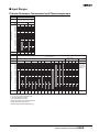
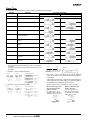
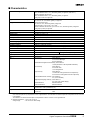
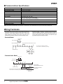
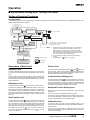
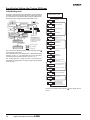
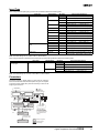
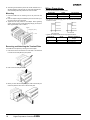
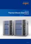
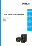
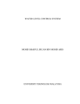
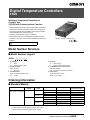
Digital Temperature Controllers E5GN Intelligent Temperature Controllers in Compact Size 1/32 DIN with Communications Function • Various temperature inputs: Thermocouple, platinum resistance thermometer, infrared temperature sensor, and analog inputs. • Auto-tuning and self-tuning available. Auto-tuning is possible even while self-tuning is being executed. • Heating or heating/cooling control is available. • Water-resistant construction (NEMA4X: equivalent to IP66). • Conforms to UL, CSA, and IEC safety standards as well as CE marking. 48(W) × 24(H) × 100(D) mm Refer to the “Safety Precautions” on page 16. Model Number Structure ■ Model Number Legend E5GN- @ @ @ @ - @ @ 1 2 3 4 5 6 4. Input type TC: Thermocouple P: Platinum resistance thermometer 5. CompoWay/F serial communications Blank: Not available FLK: CompoWay/F serial communications 6. Power supply AC100-240: 100 to 240 VAC AC/DC 24: 24 VAC/DC 1. Output type R: Relay Q: Voltage (for driving SSR) 2. Number of alarms Blank: No alarm 1: One alarm 3. Communications Blank: No communications function 03: RS-485 Ordering Information ■ Standard Models Size Power supply voltage 1/32 DIN 100 to 240 VAC 48(W) × 24(H) × 100(D) mm No. of alarm points -- 1 (see note 1) 24 VAC/VDC -- 1 (see note 1) Control output Relay Thermocouple model Platinum resistance thermometer model E5GN-RTC AC100-240 E5GN-RP AC100-240 Voltage (for driving SSR) E5GN-QTC AC100-240 E5GN-QP AC100-240 Relay E5GN-R1TC AC100-240 E5GN-R1P AC100-240 Voltage (for driving SSR) E5GN-Q1TC AC100-240 E5GN-Q1P AC100-240 E5GN-RTC AC/DC 24 E5GN-RP AC/DC 24 Voltage (for driving SSR) E5GN-QTC AC/DC 24 Relay E5GN-QP AC/DC 24 Relay E5GN-R1TC AC/DC 24 E5GN-R1P AC/DC 24 Voltage (for driving SSR) E5GN-Q1TC AC/DC 24 E5GN-Q1P AC/DC 24 Note 1. If the heating/cooling function is used, ALM1 will be used for control output and so alarm output will not be available. 2. Control output 2 for heating/cooling control is relay output. 3. Specify the power supply specifications when ordering. Digital Temperature Controllers E5GN 1 ■ Communication Models Size Power supply voltage 1/32 DIN 48(W) × 24(H) × 100(D) mm 100 to 240 VAC Communication function RS-485 24 VAC/VDC Control output Thermocouple model Platinum resistance thermometer model Relay E5GN-R03TC-FLK AC100-240 E5GN-R03P-FLK AC100-240 Voltage (for driving SSR) E5GN-Q03TC-FLK AC100-240 E5GN-Q03P-FLK AC100-240 Relay E5GN-R03TC-FLK AC/DC 24 E5GN-R03P-FLK AC/DC 24 Voltage (for driving SSR) E5GN-Q03TC-FLK AC/DC 24 E5GN-Q03P-FLK AC/DC 24 Note: Specify the power supply specifications when ordering. Specifications ■ Ratings Supply voltage 100 to 240 VAC, 50/60 Hz Operating voltage range 85% to 110% of rated supply voltage Power consumption 7 VA Sensor input Thermocouple: Platinum resistance thermometer: Infrared temperature sensor: Voltage input: Control output 24 VAC, 50/60 Hz/24 VDC 4 VA/2.5 W K, J, T, E, L, U, N, R, S, B Pt100, JPt100 10 to 70° C, 60 to 120° C, 115 to 165° C, 140 to 260° C 0 to 50 mV Relay output SPST-NO, 250 VAC, 2 A (resistive load), electrical life: 100,000 operations Voltage output 12 VDC (PNP), max. load current: 21 mA, with short-circuit protection circuit Alarm output SPST-NO, 250 VAC, 1 A (resistive load), electrical life: 100,000 operations Control method 2-PID or ON/OFF control Setting method Digital setting using front panel keys Indication method 7-segment digital display and single-lighting indicator Character height: PV: 7.0 mm; SV: 3.5 mm Other functions Multi SP, SP ramp, MV limiter, input digital filter, self-tuning, input shift, run/stop, protection func tions, etc. Ambient temperature –10 to 55° C (with no condensation or icing) Ambient humidity 25% to 85% Storage temperature –25 to 65° C (with no condensation or icing) 2 Digital Temperature Controllers E5GN ■ Input Ranges Platinum Resistance Thermometer Input/Thermocouple Input Platinum resistance thermometer input Input type Platinum resistance thermometer Temperature range Name 1800 1700 1600 1500 1400 1300 1200 1100 1000 900 800 700 600 500 400 300 200 100 0 −100 −200 Set value Pt100 JPt100 850 500.0 −200 −199.9 0 1 500.0 100.0 100.0 0.0 0.0 −199.9 2 3 4 Thermocouple input Input type Temperature range Name 1800 1700 1600 1500 1400 1300 1200 1100 1000 900 800 700 600 500 400 300 200 100 0 −100 −200 Set value ES1B Infrared Temperature Sensor Thermocouple K J T E L U N R S B 10 to 70°C 60 to 120°C Analog input 115 to 140 to 165°5C 260°C 1800 1700 Usable in the following rang es by scaling: −1999 to 9999 or −199.9 to 999.9 1700 1300 1300 850 0 to 50 mV 850 600 500.0 400.0 400 400.0 400 400.0 260 120 165 0 0 0 0 12 13 14 15 70 100 −20.0 −20.0 0 −100 0 1 2 0 0 9 10 −100 −200 3 −200 −199.9 4 17 5 6 −200 −199.9 −200 7 18 8 11 16 Applicable standards by input type are as follows: K, J, T, E, N, R, S, B: JIS C1602-1995 L: Fe-CuNi, DIN 43710-1985 U: Cu-CuNi, DIN 43710-1985 JPt100: JIS C1604-1989, JIS C1606-1989 Pt100: JIS C1604-1997, IEC751 Shaded ranges indicate default settings. Digital Temperature Controllers E5GN 3 Alarm Type For the alarm 1, select alarm types out of the 12 alarm types listed in the following table. Set Value Alarm Type Alarm Output Operation When X is positive When X is negative 0 Alarm function OFF Output OFF 1*1 Upper- and lower-limit (deviation) 2 Upper-limit (deviation) 3 Lower-limit (deviation) 4*1 Upper- and lower-limit range (deviation) *3 5*1 Upper- and lower-limit with standby se quence (deviation) *4 6 Upper-limit with standby sequence (de viation) 7 Lower-limit with standby sequence (de viation) 8 Absolute-value upper-limit 9 Absolute-value lower-limit 10 Absolute-value upper-limit with standby sequence 11 Absolute-value lower-limit with standby sequence *2 *5 *1: With set values 1, 4 and 5, the upper and lower limit values can be set independently for each alarm type, and are expressed as “L” and “H.” Following operations are for cases when an alarm set point is “X” or negative. *2: Set value: 1, Upper- and lower-limit alarm Case 1 Case 2 Case 3 (Always ON) = *3: Set value: 4, Upper- and lower-limit range Case 2 Case 1 Case 2 Example Same as for the upper- and lower-limit alarm. However, when the upper-limit and lower-limit hysteresis overlaps: Always OFF *5: Set value: 5, Upper- and lower-limit with standby sequence alarm. Always OFF when the upper-limit and lower-limit hystere sis overlaps. = Case 1 *4: Set value: 5, Upper- and lower-limit with standby sequence Case 3 (Always OFF) L H = = Set the alarm types for alarm 1 and alarm 2 independently in the initial setting level. The default setting is 2 (upper limit). With the E5AN/E5EN, perform settings similarly for alarm 3. Example: When the alarm is set ON at 110°C/°F or higher. When an alarm type other When the absolute-value than the absolute-value alarm is selected alarm is selected (For alarm types 8 to 11) (For alarm types 1 to 7) The alarm value is set as The alarm value is set as a an absolute value from the deviation from the set point. alarm value of 0°C/F. Alarm value Set point 100°C/°F 4 Digital Temperature Controllers E5GN Alarm value 0°C/°F ■ Characteristics Indication accuracy Thermocouple: (±0.5% of indicated value or ±1° C, whichever greater) ±1 digit max. (See note 1.) Platinum resistance thermometer: (±0.5% of indicated value or ±1° C, whichever greater) ±1 digit max. Analog input: ±0.5% FS±1 digit max. Temperature variation influence (See note 2.) Thermocouple input (R, S, B): (±1% of PV or ±10° C, whichever greater) ±1 digit max. Other thermocouple input: (±1% of PV or ±4° C, whichever greater) ±1 digit max. K thermocouple at –100°C max.: ±10° C max. Platinum resistance thermometer: (±1% of PV or ±2° C, whichever greater) ±1 digit max. Analog input: (±1%FS) ±1 digit max. Voltage variation influence (See note 2.) Hysteresis 0.1 to 999.9 EU (in units of 0.1 EU) Proportional band (P) 0.1 to 999.9 EU (in units of 0.1 EU) Integral time (I) 0 to 3999 s (in units of 1 s) Derivative time (D) 0 to 3999 s (in units of 1 s) Control period 1 to 99 s (in units of 1 s) Manual reset value 0.0% to 100.0% (in units of 0.1%) Alarm setting range –1999 to 9999 (decimal point position depends on input type) Sampling period 500 ms Insulation resistance 20 MΩ min. (at 500 VDC megger) Dielectric strength 2000 VAC, 50 or 60 Hz for 1 min (between different charging terminals) Vibration resistance 10 to 55 Hz, 10 m/s2 for 2 hours each in X, Y and Z directions Shock resistance 300 m/s2, 3 times each in 3 axes, 6 directions (relay: 100 m/s2) Weight Approx. 90 g Degree of protection Front panel: NEMA4X for indoor use (equivalent to IP66), rear case: IP20, terminals: IP00 Mounting bracket: approx. 10 g Memory protection EEPROM (non-volatile memory) (number of writes: 100,000) EMC ESD Immunity: Approved standards UL 61010C-1 (Listing) CSA C22.2 No. 1010.1 (Evaluated by UL.) Compliant standards EN 61010-1: IEC 61010-1: IEC 61000-4-2: 4 kV: Contact discharge 8 kV: Air discharge Radiated Electromagnetic Field Immunity: IEC 61000-4-3 10 V/m (80 MHz to 1 GHz amplitude modulated) Burst Immunity: IEC 61000-4-4: 2 kV: Power lines 1 kV: I/O signal lines Surge Immunity: IEC 61000-4-5: 1 kV: Normal mode (power lines and output lines) 2 kV: Common mode (power lines and output lines) Conducted Disturbance Immunity: IEC 61000-4-6: 3 V: (0.16 to 80 MHz) Voltage Dip/Interrupting Immunity: IEC 61000-4-11 0.5 cycle, 100% (rated voltage) Radiated Emission: EN 61326 Class A Conducted Emission: EN 61326 Class A 2001 2001 Note 1. The indication of K thermocouples in the –200 to 1300° C range, and T and N thermocouples at a temperature of –100° C or less, and U and L thermocouples at any temperature is ±2° C±1 digit maximum. The indication of B thermocouples at a temperature of 400° C or less is unrestricted. The indication of R and S thermocouples at a temperature of 200° C or less is ±3° C±1 digit maximum. 2. Ambient temperature: –10° C to 23° C to 55° C Voltage range: –15% to +10% of rated voltage Digital Temperature Controllers E5GN 5 ■ Communications Specifications Transmission path connection Multiple points Communications method RS-485 (two-wire, half duplex) Synchronization method Start-stop synchronization Baud rate 1,200/2,400/4,800/9,600/19,200 bps Transmission code ASCII Data bit length (see note) 7 or 8 bits Stop bit length (see note) 1 or 2 bits Error detection Vertical parity (none, even, odd) Frame check sequence (FCS): with SYSWAY Block check character (BCC): with CompoWay/F Flow control Not available Interface (see note) RS-485 Retry function Not available Communications buffer 40 bytes Note: The baud rate, data bit length, stop bit length, or vertical parity can be individually set using the communications setting level. Wiring Terminals • The voltage output (control output) is not electrically insulated from the internal circuits. When using a grounding thermocouple, do not connect the control output terminals to the ground. If the control output terminals are connected to the ground, errors will occur in the measured temperature values as a result of leakage current. • Standard insulation is applied to the power supply I/O sections. If reinforced insulation is required, connect the input and output ter minals to a device without any exposed current-carrying parts or to a device with standard insulation suitable for the maximum operat ing voltage of the power supply I/O section. Standard Model Control output Relay output 12 VDC 21 mA Voltage output Alarm output/control output 2/input error output Two input power supplies are available: 100 to 240 VAC or 24 VAC/VDC (no polarity). Input power supply Analog input Communication Model Control output Relay output 3 1 4 12 VDC 21 mA Voltage output 2 + − 3 4 B (+) (−) A 5 6 7 − RS485 8 9 TC Input power supply Host Two input power supplies are available: 100 to 240 VAC or 24 VAC/VDC (no polarity). + A B − B Pt + Analog input 6 Digital Temperature Controllers E5GN Thermocouple Infrared temperature sensor Temperature-resistance thermometer Dimensions Note: All units are in millimeters unless otherwise indicated. 48 35 24 3 100 (36.8) 22 44.8 *When carrying out maintenance on the E5GN, only the terminal plate can be drawn out with the terminal leads still attached. 22 Panel Cutout Mounted Separately Group Mounted +1.0 (48 × number of units -2.5) 0 +0.3 22 0 Mounting separately does not allow waterproofing. 40 min. +0.6 45 0 +0.3 22 0 • Insert the Controller through the hole in the panel from the front and push the adapter on from the rear. Push the adapter up to the back of the panel ensuring that the controller is pushed all the way in, removing any gap between the Controller, panel, and adapter. Finally, use the two screws on the adapter to secure the unit in place. • To mount the E5GN so that it is waterproof, insert the waterproof packing onto the E5GN. • When two or more E5GN Controllers are mounted, make sure that the surrounding temperature does not exceed the allowable operating temperature given in the specifications. Digital Temperature Controllers E5GN 7 Nomenclature Operation Indicators Temperature Unit 1. AL (alarm) Lights when alarm output is ON. The temperature unit is displayed when the dis play unit parameter is set to a temperature. In dication is determined by the currently selected "temperature unit" parameter set value. When this parameter is set to "°C," "c" is displayed, and when set to "°F," "f" is displayed. 2. CMW (communications writing control) Lights when communications writing is enabled and is out when it is disabled. 3. STP (stop) Lights when control of the E5GN has been stopped. During control, this indicator lights when an event or the run/stop function has been stopped. Otherwise, this indicator is out. No. 1 Display Displays the process value or parameter type. 4. OUT (control output) Lights when control output is ON. No. 2 Display Displays the set point, manipulated variable or set value (setup) of the parameter. Up Key Each press of this key increases values displayed on the No.2 display. Holding down this key continuously increases values. Level Key Press this key to select the setup level. The setup level is selected in order "operation level" ←→ "adjustment level," "initial setting level" ←→ "communications setting level." Mode Key Press this key to select parameters within each level. 8 Digital Temperature Controllers E5GN Down Key Each press of this key decreases values displayed on the No.2 display. Holding down this key continuously decreases values. Level + Mode Key This key combination sets the E5GN to the "protect level." Operation ■ Specification Setting after Turning ON Power Outline of Operation Procedures Key Operation In the following descriptions, all the parameters are introduced in the display sequence. Some parameters may not be displayed depending on the protect settings and operation conditions. Power ON Operation level Adjustment level key Less than 1 second key 1 second min. key 3 seconds min. Initial setting level 25 + key 1 second min. key Display flashes when key held 100 down for more than 1 second. Control stops. Communica tions setting level key Less than 1 second Password input set value "−169" key 1 second min. + key Display flashes when key pressed. Advanced function setting level Password input set value "1201" Calibration level 25 100 key + 3 seconds min. Protect level The time taken to move to the protect level can be adjusted by changing the "Move to protect level time" setting. Note: 1. Of these levels, the initial setting level, communications setting level, advanced function setting level and cali bration level can be used only when control has stop ped. Note that control is stopped when these four levels are selected. When switched back to the operation level from one of these levels, control will start. 2. For the calibration mode, refer to the relevant User's Manual. 3. On the E5GN, the Key is the Key. Control in progress Control stopped Level change Description of Each Level Operation Level This level is displayed when you turn the power ON. You can move to the protect level, initial setting level and adjustment level from this level. Normally, select this level during operation. During operation, the process value, set point and manipulated variable can be monitored, and the alarm value and upper- and lower-limit alarms can be moni tored and modified. Adjustment Level To select this level, press the key once for less than one second. This level is for entering set values and offset values for control. This level contains parameters for setting the set values, AT (auto-tuning), communications writing enable/disable, hysteresis, multi-SP, input shift values, heater burnout alarm (HBA) and PID constants. You can move to the top parameter of the operation level or initial setting level from here. Initial Setting Level Protect Level To select this level, simultaneously press the and keys for at least 3 seconds. This level is to prevent unwanted or accidental mod ification of parameters. Protected levels will not be displayed, and so the parameters in that level cannot be modified. Communications Setting Level To select this level, press the key once for less than one second in the initial setting level. When the communications function is used, set the communications conditions in this level. Communicating with a personal computer (host computer) allows set points to be read and written, and manipulated variables to be monitored. Advanced Function Setting Level To select this level, you must enter the password (“-169”) in the initial setting level. You can move only to the calibration level from this level. This level is for setting the automatic return of display mode, MV lim iter, event input assignment, standby sequence, alarm hysteresis, ST (self-tune) and to move to the user calibration level. To select this level, press the key for at least three seconds in the operation level. This level is for specifying the input type, selecting the control method, control period, setting direct/reverse action and alarm type. You can move to the advanced function setting level or communications setting level from this initial setting level. To return to Calibration Level the operation level, press the key for at least one second. To move to the communications setting level, press the key once for less than one second. You cannot move to other levels by operating the keys on the front panel from the calibration level. To cancel this level, turn the power OFF then back ON again. To select this level, you must enter the password (“1201”) in the advanced function setting level. This level is for offsetting deviation in the input circuit. Digital Temperature Controllers E5GN 9 Specification Setting after Turning ON Power Initial Setting Level This level is used for setting basic specifications of the Temperature Controller. Using this level, set the input type for selecting the input to be connected such as the thermocouple or platinum resistance ther mometer and set the range of set point and the alarm mode. Initial Setting Level Input type in-t 0 in-h 100 in-l 0 dp 0 d-u c sl-h 1300 sl-l -200 The move from the operation level to the initial setting level, press key for three seconds or more. cntl onof The initial setting level is not displayed when “initial/communications protection” is set to “2.” This initial setting level can be used when “initial setting/communications protection” is set to “0” or “1.” s-hc stnd The “scaling upper limit,” “scaling lower limit,” and “decimal point” parameters are displayed when an analog voltage input is selected as the input type. st on cp 20 c-cp 20 ore? or-r alt1 2 amo? 0 key + Display flashes when key pressed. Power ON Operation level Adjustment level key Less than 1 second key 1 second min. key 3 seconds min. Initial setting level 25 100 key + 1 second min. 25 Control stops. Communications setting key level 100 key + 3 seconds min. Scaling upper limit Scaling lower limit Decimal point Protect level Less than 1 second key 1 second min. Password input set value "−169" Advanced function setting level The time taken to move to the protect level can be adjusted by changing the "Move to protect level time" setting. c Password input set value "1201" Temperature unit °C, °F SP upper limit Limit the set point. Control in progress Calibration level Control stopped c SP lower limit Level change PID ON/OFF Standard or heating/cooling ST For input type of temperature, standard, or PID Control period (heating) Set the pulse output cycle. Control period (cooling) Direct/reverse operation Alarm 1 type Move to advanced function setting level Displayed when initial setting/ communications protection is set to 0 To return to the operation level, press the second. 10 Digital Temperature Controllers E5GN key for longer than one Input Type When using a thermocouple input type, follow the specifications listed in the following table. Input Type Thermocouple input type Specifications Thermocouple K J T Analog input Input Temperature Range –200 to 1300 (° C) /–300 to 2300 (° F) 1 –20.0 to 500.0 (° C) /0.0 to 900.0 (° F) 2 –100 to 850 (° C) /–100 to 1500 (° F) 3 –20.0 to 400.0 (° C) /0.0 to 750.0 (° F) 4 –200 to 400 (° C) /–300 to 700 (° F) 17 –199.9 to 400.0 (° C) /–199.9 to 700 (° F) E 5 0 to 600 (° C) /0 to 1100 (° F) L 6 –100 to 850 (° C) /–100 to 1500 (° F) 7 –200 to 400 (° C) /–300 to 700 (° F) 18 –199.9 to 400.0 (° C) /–199.9 to 700 (° F) U Infrared temperature sensor ES1B Set Value 0 N 8 –200 to 1300 (° C) /–300 to 2300 (° F) R 9 0 to 1700 (° C) /0 to 3000 (° F) S 10 0 to 1700 (° C) /0 to 3000 (° F) B 11 100 to 1800 (° C) /300 to 3200 (° F) /0 to 190 (° F) 10 to 70° C 12 0 to 90 (° C) 60 to 120° C 13 0 to 120 (° C) /0 to 240 (° F) 115 to 165° C 14 0 to 165 (° C) /0 to 320 (° F) /0 to 500 (° F) 140 to 260° C 15 0 to 260 (° C) 0 to 50 mV 16 One of following ranges depending on the re sults of scaling: 1999 to 9999, 199.9 to 999.9 Note: The initial settings are: 0: −200 to 1300° C/−300 to 2300° F. When using the platinum resistance thermometer input type, follow the specifications listed in the following table. Input Type Specifications Platinum resistance thermom Platinum resistance thermom Pt100 eter input type eter JPt100 Set Value Input Temperature Range 0 –200 to 850 (° C) 1 –199.9 to 500.0 (° C) /–199.9 to 900.0 (° F) /–300 to 1500 (° F) 2 0.0 to 100.0 (° C) 3 –199.9 to 500.0 (° C) /–199.9 to 900.0 (° F) /0.0 to 210.0 (° F) 4 0.0 to 100.0 (° C) /0.0 to 210.0 (° F) Note: The initial settings are: 0: Pt100 −200 to 850° C/−300 to 1500° F. Parameters Parameters related to setting items for each level are marked in boxes in the flowcharts and brief descriptions are given as required. At the end of each setting item, press the mode key to return to the beginning of each level. Power ON Operation level key 1 second min. + key Display flashes when key pressed. Adjustment level key Less than 1 second key 3 seconds min. 25 + key 1 second + key min. Display flashes when key held 100 down for more than 1 second. Control stops. Communica tions setting key level Initial setting level 25 100 + key 3 seconds min. Protect level Less than 1 second key 1 second min. Password input set value "−169" Advanced function setting level The time taken to move to the protect level can be adjusted by changing the "Move to protect level time" setting. Password input set value "1201" Control in progress Calibration level Control stopped Level change Digital Temperature Controllers E5GN 11 Press the O key for at least 1 s. Initial Setting Level Advanced Function Setting Level Press the Parameter initialization init off mspu off sprt off rest a Input type Multi-SP uses SP ramp time unit Alarm 1 open in alarm c n-o c st-b alfa in-l 0 dp 0 Scaling upper limit Scaling lower limit Temperature unit c °C, °F SP upper limit sl-h 1300 Limit the set point. SP lower limit ST stable range sl-l -200 α cntl onof 15.0 PID ON/OFF 0.65 ol-h 105.0 ol-l 100 0.2 c c in-h d-u Alarm 1 hysteresis alh1 0 Decimal point Standby sequence reset method al1n in-t O key for at least 3 s. (Display flashes for at least 1 s.) Displays other than that for switching between automatic and manual Standard or heating/cooling s-hc stnd MV upper limit ST st on cp 20 c-cp 20 For input type of temperature, standard, or PID MV lower limit -5.0 Control period (heating) Set the pulse output cycle. Input digital filter inf p?ad 0.0 Control period (cooling) Additional PV display off Direct/reverse operation ore? or-r MV display o-dp off Alarm 1 type alt1 2 amo? 0 Automatic return of display mode ret a1lt off Alarm 1 latch Move to advanced function setting level Displayed when initial setting/ communications protection is set to 0 Moved by setting password (−169) off O Press the key less than 1 s. Communications Setting Level Move to protect level time prlt 3 sero off Displayed only for models with communications. Changes are effective after cycling power or after a software reset. Input error output u-no Communications 1 Unit No. CompoWay/F (SYSWAY) only Cold junction compensation method cjc on rlr? off cmo? 0 Baud rate bps 9.6 len 7 sbit 2 MB command logic switching Data bits Move to calibration level Stop bits prty 12 Digital Temperature Controllers E5GN Communications e?en parity O Press the key less than 1 s. Power ON Press the O key less than 1 s. Press the O Adjustment Level Operation Level c c key less than 1 s. AT execute/cancel Process value 25 Added when PV display is added. 100 c c cmwt off sp-0 0 sp-1 0 sp-2 0 sp-3 0 in5 0.0 Communications writing m-sp 0 sp-m 0 r-5 run al-1 0 c SP ramp monitor c Run/stop c off Process value/set point 25 Multi-SP set point setting c at c Alarm value 1 c Upper-limit alarm value 1 al1h c 0 Lower-limit alarm value 1 al1l Set either of these parameters. c 0 MV monitor (heating) SP used by multi-SP SP 2 SP 3 insh 0.0 Temperature input shift 1-point shift Set either of these parameters. Upper-limit temperature input in5l 0.0 p 8.0 i 233 d 40 Lower-limit temperature input 0.0 c MV monitor (cooling) c-o SP 1 2-point shift c o SP 0 0.0 Proportional band Integral time O Press the +M keys for at least 1 s. O +M Press the keys for at least 3 s. Display flashes. PID settings Derivative time Protect Level The time taken to move to the protect level can be adjusted by changing the "Move to protect level time" setting. c-sc Cooling 1.00 coefficient Heating/cooling Operation/adjustment protection Restricts displaying and modifying menus in operation, adjustment, and manual control levels. oapt 0 icpt Initial setting/communications protection This protect level restricts movement to the 1 initial setting, communications setting, and advanced function setting levels. wtpt Setting change protection Protects changes to setups by operating the off front panel keys. c c c Dead band c-db 0.0 of-r 50.0 hys 1.0 Manual reset value Clear the offset during stabilization of P or PD control. Hysteresis (heating) Hysteresis settings Hysteresis (cooling) chys 1.0 Note: These diagrams show all the parameters that may be displayed. Depending on the specifications of the model used, there may be some parameters that are not displayed. Digital Temperature Controllers E5GN 13 Input Shift Setting Change Protection All points in the sensor range are shifted by the value set as the tem perature input shift value. This protect level protects setup from being changed by operating the keys on the front panel. Example Set value Input shift setting Temperature measured by sensor Temperature display 0 (no shift) 100° C 100° C 10 (shifted +10° C) 100° C 110° C 100° C 90° C Protect Level oapt 0 icpt 1 wtpt off Operation/adjustment protection Restricts displaying and modifying menus in operation, adjustment, and manual control levels. Initial setting/communications protection This protect level restricts movement to the initial setting, communications setting, and advanced function setting levels. Setting change protection Protects changes to setups by operating the front panel keys. Operation/Adjustment Protection The following table shows the relationship between set values and the range of protection. Level Operation level Set value PV 0 1 2 3 PV/SP Other Adjustment level X X X X X When this parameter is set to “0,” parameters are not protected. Default setting: 0 : Can be displayed and changed �: Can be displayed X : Cannot be displayed and move to other levels not possible Initial Setting/Communications Protection This protect level restricts movement to the initial setting level, com munications setting level and advanced function setting level. Set Initial setting level Communication value s setting level Advanced function setting level 0 1 X 2 X X X Default setting: 1 : Move to other levels possible X: Move to other levels not possible 14 Setup can be changed by key operation. ON Setup cannot be changed by key operation. (The protect level, can be changed.) Default setting: OFF –10 (shifted –10° C) Digital Temperature Controllers E5GN Description OFF Communications Setting Level Set the E5GN communications specifications in the communications setting level. For setting communications parameters, use the E5GN panel. The communications parameters and their settings are listed in the following table. Parameter Displayed characters Set (monitor) value Set value Communications unit No. u-no 0 to 99 0.1 to 99 Baud rate bps 1.2/2.4/4.8/9.6/19.2 (kbps) 1.2/2.4/4.8/9.6/19.2 Data bits len 7/8 (bit) 7/8 (bit) Stop bits sbit 1/2 1/2 (bit) Parity prty None, even, odd none/eVen/odd Note: The highlighted values indicate default settings. Communications Unit No. (u-no) Before executing communications with the E5GN, set the communi cations unit No., baud rate, etc., through key operations as described below. As for other operations, refer to relevant Operation Manual. When communicating with the host computer, the unit number must be set in each Temperature Controller so that the host computer can identify each Temperature Controller. The number can be set in a range from 0 to 99 in increments of 1. The default setting is 1. When using more than one Unit, be careful not to use the same number twice. Duplicate settings will cause malfunction. This value becomes valid when the power is turned OFF and ON again. 1. Press the key for at least three seconds in the “operation level.” The level moves to the “initial setting level.” 2. Press the key for less than one second. The “initial setting level” moves to the “communications setting level.” 3. Pressing the following figure. 4. Press the key advances the parameters as shown in the Baud Rate (bps) or keys to change the parameter setups. Communications 1 unit No. u-no Baud rate bps 9.6 len 7 sbit 2 prty Note: On the E5GN, the Use this parameter to set the speed of communications with the host computer. It can be set to one of the following values; 1.2 (1200 bps), 2.4 (2400 bps), 4.8 (4800 bps), 9.6 (9600 bps), and 19.2 (19200 bps). This setting becomes valid when the power is turned OFF and ON again. Data Bits (len) Data bits Use this parameter to change the communications data bit length to 7 bits or 8 bits. Stop bits Stop Bits (sbit) Use this parameter to change the communications stop bit to 1 or 2. Communications e?en parity Key is the Communications Parity (prty) Use this parameter to set the communications parity to None, Even, or Odd. Key. Set each communications parameter to match those of the communi cating personal computer. Troubleshooting When an error occurs, an error code will be displayed on the No. 1 display. Check the contents of an error and take appropriate countermeasures. No.1 display Contents Countermeasure Output status Control output s.err (S. Err) Alarm output Input error (See note.) Check that the input wiring is correct, that there is no discon OFF nection or short-circuit, and that the input type is correct. (Thermocouple input short-circuits cannot be detected.) Handled as ab normally high temperature A/D converter error (See note.) After noting the error, reset the power. If the display does not OFF change, replacement is necessary. If the error is removed, it is possible that the original error was caused by noise. Check that there are no possible sources of noise. OFF e111 (E111) Memory error h.err (H. Err) HB error (See note.) Reset the power. If the display does not change, replacement OFF is necessary. If the error is removed, it is possible that the OFF original error was caused by noise. Check that there are no possible sources of noise. OFF OFF Note 1. If the input is within the range for which control is possible but outside the displayable range (–1999 (–199.9) to 9999 (999.9)), cccc will be displayed if the value is less than –1999 (–199.9), and will be displayed if it is greater than 9999 (999.9). Control output and alarm output will operate normally for either of these displays. Refer to the relevant User’s Manual for details on the ranges for which control is possible. 2. These errors are displayed only when the Controller is set to display the present value or the present value and the set value. They are not displayed in other statuses. cccc Digital Temperature Controllers E5GN 15 Safety Precautions !CAUTION Do not touch the terminals while power is being supplied. Doing so may occasionally result in minor injury due to electric shock. Do not allow pieces of metal, wire clippings, or fine metallic shavings or filings from installation to enter the product. Doing so may occasionally result in electric shock, fire, or malfunction. Do not use the product where subject to flammable or explosive gas. Otherwise, minor injury from explosion may occasionally occur. Do not leave the conversion cable connected to the product. Malfunction may occur due to noise in the cable. Do not use the Temperature Controller or Conversion Cable if it is damaged. Doing so may occasionally result in minor electric shock or fire. Never disassemble, modify, or repair the product or touch any of the internal parts. Minor electric shock, fire, or malfunction may occasionally occur. CAUTION - Risk of Fire and Electric Shock a) This product is UL listed as Open Type Process Control Equipment. It must be mounted in an enclosure that does not allow fire to escape externally. b) More than one disconnect switch may be required to de-energize the equipment before servicing the product. c) Signal inputs are SELV, limited energy. (See note 1.) d) Caution: To reduce the risk of fire or electric shock, do not interconnect the outputs of different Class 2 circuits. (See note 2.) If the output relays are used past their life expectancy, contact fusing or burning may occasionally occur. Always consider the application conditions and use the output relays within their rated load and electrical life expectancy. The life expectancy of output relays varies considerably with the output load and switching conditions. Tighten the terminal screws properly. Tighten them to a torque of 0.24 N·m (2.5 kgf·cm) max. on terminals 1 to 6. Tighten them to a torque of 0.13 N·m (1.4 kgf·cm) max. on terminals 7 to 9. Loose screws may cause malfunction. Set the parameters of the product so that they are suitable for the system being controlled. If they are not suitable, unexpected operation may occasionally result in property damage or accidents. A malfunction in the product may occasionally make control operations impossible or prevent alarm outputs, resulting in property damage. To maintain safety in the event of malfunction of the product, take appropriate safety measures, such as installing a monitoring device on a separate line. 16 Digital Temperature Controllers E5GN A semiconductor is used in the output section of long-life relays. If excessive noise or surge is impressed on the output terminals, a short-circuit failure is likely to occur. If the output remains shorted, fire will occur due to overheating of the heater or other cause. Take measures in the overall system to prevent excessive temperature increase and to prevent fire from spreading. Do not allow pieces of metal or wire cuttings to get inside connectors. Failure to do so may occasionally result in minor electric shock, fire, or damage to equipment. Note: 1. An SELV circuit is one separated from the power supply with double insulation or reinforced insulation, that does not exceed 30 V r.m.s. and 42.4 V peak or 60 VDC. 2. A class 2 power supply is one tested and certified by UL as have the current and voltage of the secondary output restricted to specific levels. Precautions for Safe Use Be sure to observe the following precautions to prevent malfunction or adverse affects on the performance or functionality of the product. Not doing so may occasionally result in faulty operation. 1. This product is specifically designed for indoor use only. Do not use this product in the following places: • Places directly subject to heat radiated from heating equipment. • Places subject to splashing liquid or oil atmosphere. • Places subject to direct sunlight. • Places subject to dust or corrosive gas (in particular, sulfide gas and ammonia gas). • Places subject to intense temperature change. • Places subject to icing and condensation. • Places subject to vibration and large shocks. 2. Use and store the product within the rated ambient temperature and humidity. Gang-mounting two or more Temperature Controllers, or mounting Temperature Controllers above each other may cause heat to build up inside the Temperature Controllers, which will shorten their service life. In such a case, use forced cooling by fans or other means of air ventilation to cool down the Temperature Controllers. 3. To allow heat to escape, do not block the area around the product. Do not block the ventilation holes on the product. 4. Be sure to wire properly with correct polarity of terminals. 5. Use the specified size (M3.5, width 7.2 mm or less) crimped terminals for wiring. To connect bare wires to the terminal block, use stranded or solid copper wires with a gage of AWG24 to AWG14 (equal to a cross-sectional area of 0.205 to 2.081 mm2). (The stripping length is 5 to 6 mm.) Up to two wires or two crimp terminals can be inserted into a single terminal. 6. Do not wire the terminals that are not used. 7. To avoid inductive noise, keep the wiring for the product’s terminal block away from power cables carry high voltages or large currents. Also, do not wire power lines together with or parallel to product wiring. Using shielded cables and using separate conduits or ducts is recommended. Attach a surge suppressor or noise filter to peripheral devices that generate noise (in particular, motors, transformers, solenoids, magnetic coils, or other equipment that have an inductance component). When a noise filter is used at the power supply, first check the voltage or current, and attach the noise filter as close as possible to the product. Allow as much space as possible between the product and devices that generate powerful high frequencies (high-frequency welders, high-frequency sewing machines, etc.) or surge. 8. Use this product within the rated load and power supply. 9. Make sure that the rated voltage is attained within two seconds of turning ON the power using a switch or relay contact. If the voltage is applied gradually, the power may not be reset or output malfunctions may occur. 10. Make sure that the Temperature Controller has 30 minutes or more to warm up after turning ON the power before starting actual control operations to ensure the correct temperature display. 11. When executing self-tuning, turn ON power to the load (e.g., heater) at the same time as or before supplying power to the product. If power is turned ON to the product before turning ON power to the load, self-tuning will not be performed properly and optimum control will not be achieved. 12. A switch or circuit breaker must be provided close to the product. The switch or circuit breaker must be within easy reach of the operator, and must be marked as a disconnecting means for this unit. 13. Always turn OFF the power supply before pulling out the interior of the product, and never touch nor apply shock to the terminals or electronic components. When inserting the interior of the product, do not allow the electronic components to touch the case. 14. Do not use paint thinner or similar chemical to clean with. Use standard grade alcohol. 15. Design the system (e.g., control panel) considering the 2 seconds of delay that the product's output to be set after power ON. 16. The output may turn OFF when shifting to certain levels. Take this into consideration when performing control. 17. The EEPROM has a limited write life. When overwriting data frequently, e.g., via communications, use RAM Mode. Precautions for Correct Use Service Life 1. Use the product within the following temperature and humidity ranges: Temperature: –10 to 55° C (with no icing or condensation) Humidity: 25% to 85% If the product is installed inside a control board, the ambient temperature must be kept to under 55° C, including the temperature around the product. 2. The service life of electronic devices like Temperature Controllers is determined not only by the number of times the relay is switched but also by the service life of internal electronic components. Component service life is affected by the ambient temperature: the higher the temperature, the shorter the service life and, the lower the temperature, the longer the service life. Therefore, the service life can be extended by lowering the temperature of the Temperature Controller. 3. When two or more Temperature Controllers are mounted horizontally close to each other or vertically next to one another, the internal temperature will increase due to heat radiated by the Temperature Controllers and the service life will decrease. In such a case, use forced cooling by fans or other means of air ventilation to cool down the Temperature Controllers. When providing forced cooling, however, be careful not to cool down the terminals sections alone to avoid measurement errors. Measurement Accuracy 1. When extending or connecting the thermocouple lead wire, be sure to use compensating wires that match the thermocouple types. 2. When extending or connecting the lead wire of the platinum resistance thermometer, be sure to use wires that have low resistance and keep the resistance of the three lead wires the same. 3. Mount the product so that it is horizontally level. 4. If the measurement accuracy is low, check to see if input shift has been set correctly. Waterproofing The degree of protection is as shown below. Sections without any specification on their degree of protection or those with IP@0 are not waterproof. Front panel: NEMA4X for indoor use (equivalent to IP66) Rear case: IP20, Terminal section: IP00 Operating Precautions 1. It takes approximately two seconds for the outputs to turn ON from after the power supply is turned ON. Due consideration must be given to this time when incorporating Temperature Controllers in a sequence circuit. 2. When using self-tuning, turn ON power for the load (e.g., heater) at the same time as or before supplying power to the Temperature Controller. If power is turned ON for the Temperature Controller before turning ON power for the load, self-tuning will not be performed properly and optimum control will not be achieved. 3. When starting operation after the Temperature Controller has warmed up, turn OFF the power and then turn it ON again at the same time as turning ON power for the load. (Instead of turning the Temperature Controller OFF and ON again, switching from STOP mode to RUN mode can also be used.) Digital Temperature Controllers E5GN 17 4. Avoid using the Controller in places near a radio, television set, or wireless installing. These devices can cause radio disturbances which adversely affect the performance of the Controller. Wiring Precautions • Connect the terminals as specified below. Terminal No. Mounting 1. Insert the E5GN into the mounting hole in the panel from the front. 2. Push the adapter along the E5GN body from the terminals up to the panel, and secure it temporarily. 3. Tighten the two fixing screws on the adapter. When tightening screws, tighten the two screws alternately keeping the torque to within approximately 0.29 to 0.39 N·m. Cables Pin terminals 1 to 6 AWG24 to AWG14 2.1 dia. max. 7 to 9 AWG28 to AWG22 1.3 dia. max. • The exposed current-carrying part to be inserted into terminals must be 5 to 6 mm. Adapter 5 to 6 mm Waterproof packing Panel Pin terminal Electrical wire • Tighten the terminal screws to the torque specified below. Terminal No. Removing and Attaching the Terminal Plate The E5GN can be replaced by removing the terminal plate. 1. Press down hard on the fasteners on both sides of the terminals to unlock the terminal plate and pull upwards. 2. Draw out the terminal plate as it is. 3. Before you insert the terminal plate again, make sure that the pins match the positions of the holes in the terminal plate. 18 Digital Temperature Controllers E5GN 5 to 6 mm Screw Maximum tightening torque 1 to 6 M2.6 0.23 to 0.25 N·m 7 to 9 M2 0.12 to 0.14 N·m Terms and Conditions of Sale 1. Offer; Acceptance. These terms and conditions (these "Terms") are deemed part of all quotes, agreements, purchase orders, acknowledgments, price lists, catalogs, manuals, brochures and other documents, whether electronic or in writing, relating to the sale of products or services (collectively, the "Products") by Omron Electronics LLC and its subsidiary companies (“Omron”). Omron objects to any terms or conditions proposed in Buyer’s purchase order or other documents which are inconsistent with, or in addition to, these Terms. 2. Prices; Payment Terms. All prices stated are current, subject to change with out notice by Omron. Omron reserves the right to increase or decrease prices on any unshipped portions of outstanding orders. Payments for Products are due net 30 days unless otherwise stated in the invoice. 3. Discounts. Cash discounts, if any, will apply only on the net amount of invoices sent to Buyer after deducting transportation charges, taxes and duties, and will be allowed only if (i) the invoice is paid according to Omron’s payment terms and (ii) Buyer has no past due amounts. 4. Interest. Omron, at its option, may charge Buyer 1-1/2% interest per month or the maximum legal rate, whichever is less, on any balance not paid within the stated terms. 5. Orders. Omron will accept no order less than $200 net billing. 6. Governmental Approvals. Buyer shall be responsible for, and shall bear all costs involved in, obtaining any government approvals required for the impor tation or sale of the Products. 7. Taxes. All taxes, duties and other governmental charges (other than general real property and income taxes), including any interest or penalties thereon, imposed directly or indirectly on Omron or required to be collected directly or indirectly by Omron for the manufacture, production, sale, delivery, importa tion, consumption or use of the Products sold hereunder (including customs duties and sales, excise, use, turnover and license taxes) shall be charged to and remitted by Buyer to Omron. 8. Financial. If the financial position of Buyer at any time becomes unsatisfactory to Omron, Omron reserves the right to stop shipments or require satisfactory security or payment in advance. If Buyer fails to make payment or otherwise comply with these Terms or any related agreement, Omron may (without liabil ity and in addition to other remedies) cancel any unshipped portion of Prod ucts sold hereunder and stop any Products in transit until Buyer pays all amounts, including amounts payable hereunder, whether or not then due, which are owing to it by Buyer. Buyer shall in any event remain liable for all unpaid accounts. 9. Cancellation; Etc. Orders are not subject to rescheduling or cancellation unless Buyer indemnifies Omron against all related costs or expenses. 10. Force Majeure. Omron shall not be liable for any delay or failure in delivery resulting from causes beyond its control, including earthquakes, fires, floods, strikes or other labor disputes, shortage of labor or materials, accidents to machinery, acts of sabotage, riots, delay in or lack of transportation or the requirements of any government authority. 11. Shipping; Delivery. Unless otherwise expressly agreed in writing by Omron: a. Shipments shall be by a carrier selected by Omron; Omron will not drop ship except in “break down” situations. b. Such carrier shall act as the agent of Buyer and delivery to such carrier shall constitute delivery to Buyer; c. All sales and shipments of Products shall be FOB shipping point (unless otherwise stated in writing by Omron), at which point title and risk of loss shall pass from Omron to Buyer; provided that Omron shall retain a security interest in the Products until the full purchase price is paid; d. Delivery and shipping dates are estimates only; and e. Omron will package Products as it deems proper for protection against normal handling and extra charges apply to special conditions. 12. Claims. Any claim by Buyer against Omron for shortage or damage to the Products occurring before delivery to the carrier must be presented in writing to Omron within 30 days of receipt of shipment and include the original trans portation bill signed by the carrier noting that the carrier received the Products from Omron in the condition claimed. 13. Warranties. (a) Exclusive Warranty. Omron’s exclusive warranty is that the Products will be free from defects in materials and workmanship for a period of twelve months from the date of sale by Omron (or such other period expressed in writing by Omron). Omron disclaims all other warranties, express or implied. (b) Limitations. OMRON MAKES NO WARRANTY OR REPRESENTATION, EXPRESS OR IMPLIED, ABOUT NON-INFRINGEMENT, MERCHANTABIL 14. 15. 16. 17. 18. ITY OR FITNESS FOR A PARTICULAR PURPOSE OF THE PRODUCTS. BUYER ACKNOWLEDGES THAT IT ALONE HAS DETERMINED THAT THE PRODUCTS WILL SUITABLY MEET THE REQUIREMENTS OF THEIR INTENDED USE. Omron further disclaims all warranties and responsibility of any type for claims or expenses based on infringement by the Products or oth erwise of any intellectual property right. (c) Buyer Remedy. Omron’s sole obli gation hereunder shall be, at Omron’s election, to (i) replace (in the form originally shipped with Buyer responsible for labor charges for removal or replacement thereof) the non-complying Product, (ii) repair the non-complying Product, or (iii) repay or credit Buyer an amount equal to the purchase price of the non-complying Product; provided that in no event shall Omron be responsi ble for warranty, repair, indemnity or any other claims or expenses regarding the Products unless Omron’s analysis confirms that the Products were prop erly handled, stored, installed and maintained and not subject to contamina tion, abuse, misuse or inappropriate modification. Return of any Products by Buyer must be approved in writing by Omron before shipment. Omron Compa nies shall not be liable for the suitability or unsuitability or the results from the use of Products in combination with any electrical or electronic components, circuits, system assemblies or any other materials or substances or environ ments. Any advice, recommendations or information given orally or in writing, are not to be construed as an amendment or addition to the above warranty. See http://oeweb.omron.com or contact your Omron representative for pub lished information. Limitation on Liability; Etc. OMRON COMPANIES SHALL NOT BE LIABLE FOR SPECIAL, INDIRECT, INCIDENTAL, OR CONSEQUENTIAL DAMAGES, LOSS OF PROFITS OR PRODUCTION OR COMMERCIAL LOSS IN ANY WAY CONNECTED WITH THE PRODUCTS, WHETHER SUCH CLAIM IS BASED IN CONTRACT, WARRANTY, NEGLIGENCE OR STRICT LIABILITY. Further, in no event shall liability of Omron Companies exceed the individual price of the Product on which liability is asserted. Indemnities. Buyer shall indemnify and hold harmless Omron Companies and their employees from and against all liabilities, losses, claims, costs and expenses (including attorney's fees and expenses) related to any claim, inves tigation, litigation or proceeding (whether or not Omron is a party) which arises or is alleged to arise from Buyer's acts or omissions under these Terms or in any way with respect to the Products. Without limiting the foregoing, Buyer (at its own expense) shall indemnify and hold harmless Omron and defend or set tle any action brought against such Companies to the extent based on a claim that any Product made to Buyer specifications infringed intellectual property rights of another party. Property; Confidentiality. Any intellectual property in the Products is the exclu sive property of Omron Companies and Buyer shall not attempt to duplicate it in any way without the written permission of Omron. Notwithstanding any charges to Buyer for engineering or tooling, all engineering and tooling shall remain the exclusive property of Omron. All information and materials supplied by Omron to Buyer relating to the Products are confidential and proprietary, and Buyer shall limit distribution thereof to its trusted employees and strictly prevent disclosure to any third party. Export Controls. Buyer shall comply with all applicable laws, regulations and licenses regarding (i) export of products or information; (iii) sale of products to “forbidden” or other proscribed persons; and (ii) disclosure to non-citizens of regulated technology or information. Miscellaneous. (a) Waiver. No failure or delay by Omron in exercising any right and no course of dealing between Buyer and Omron shall operate as a waiver of rights by Omron. (b) Assignment. Buyer may not assign its rights hereunder without Omron's written consent. (c) Law. These Terms are governed by the law of the jurisdiction of the home office of the Omron company from which Buyer is purchasing the Products (without regard to conflict of law princi ples). (d) Amendment. These Terms constitute the entire agreement between Buyer and Omron relating to the Products, and no provision may be changed or waived unless in writing signed by the parties. (e) Severability. If any provi sion hereof is rendered ineffective or invalid, such provision shall not invalidate any other provision. (f) Setoff. Buyer shall have no right to set off any amounts against the amount owing in respect of this invoice. (g) Definitions. As used herein, “including” means “including without limitation”; and “Omron Compa nies” (or similar words) mean Omron Corporation and any direct or indirect subsidiary or affiliate thereof. Certain Precautions on Specifications and Use 1. Suitability of Use. Omron Companies shall not be responsible for conformity with any standards, codes or regulations which apply to the combination of the Product in the Buyer’s application or use of the Product. At Buyer’s request, Omron will provide applicable third party certification documents identifying ratings and limitations of use which apply to the Product. This information by itself is not sufficient for a complete determination of the suitability of the Prod uct in combination with the end product, machine, system, or other application or use. Buyer shall be solely responsible for determining appropriateness of the particular Product with respect to Buyer’s application, product or system. Buyer shall take application responsibility in all cases but the following is a non-exhaustive list of applications for which particular attention must be given: (i) Outdoor use, uses involving potential chemical contamination or electrical interference, or conditions or uses not described in this document. (ii) Use in consumer products or any use in significant quantities. (iii) Energy control systems, combustion systems, railroad systems, aviation systems, medical equipment, amusement machines, vehicles, safety equip ment, and installations subject to separate industry or government regulations. (iv) Systems, machines and equipment that could present a risk to life or prop erty. Please know and observe all prohibitions of use applicable to this Product. NEVER USE THE PRODUCT FOR AN APPLICATION INVOLVING SERIOUS RISK TO LIFE OR PROPERTY OR IN LARGE QUANTITIES WITHOUT ENSURING THAT THE SYSTEM AS A WHOLE HAS BEEN DESIGNED TO 2. 3. 4. 5. ADDRESS THE RISKS, AND THAT THE OMRON’S PRODUCT IS PROP ERLY RATED AND INSTALLED FOR THE INTENDED USE WITHIN THE OVERALL EQUIPMENT OR SYSTEM. Programmable Products. Omron Companies shall not be responsible for the user’s programming of a programmable Product, or any consequence thereof. Performance Data. Data presented in Omron Company websites, catalogs and other materials is provided as a guide for the user in determining suitabil ity and does not constitute a warranty. It may represent the result of Omron’s test conditions, and the user must correlate it to actual application require ments. Actual performance is subject to the Omron’s Warranty and Limitations of Liability. Change in Specifications. Product specifications and accessories may be changed at any time based on improvements and other reasons. It is our prac tice to change part numbers when published ratings or features are changed, or when significant construction changes are made. However, some specifica tions of the Product may be changed without any notice. When in doubt, spe cial part numbers may be assigned to fix or establish key specifications for your application. Please consult with your Omron’s representative at any time to confirm actual specifications of purchased Product. Errors and Omissions. Information presented by Omron Companies has been checked and is believed to be accurate; however, no responsibility is assumed for clerical, typographical or proofreading errors or omissions. Digital Temperature Controllers E5GN 19 Complete “Terms and Conditions of Sale” for product purchase and use are on Omron’s website at www.omron.com/oei – under the “About Us” tab, in the Legal Matters section. ALL DIMENSIONS SHOWN ARE IN MILLIMETERS. To convert millimeters into inches, multiply by 0.03937. To convert grams into ounces, multiply by 0.03527. OMRON ELECTRONICS LLC OMRON CANADA, INC. OMRON ON-LINE One Commerce Drive Schaumburg, IL 60173 885 Milner Avenue Toronto, Ontario M1B 5V8 847-843-7900 416-286-6465 Global - http://www.omron.com USA - http://www.omron.com/oei Canada - http://www.omron.ca For US technical support or other inquiries: 800-556-6766 Cat. No. H148-E3-01A 06/06 Specifications subject to change without notice Printed in USA