1
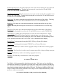
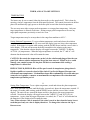
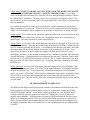
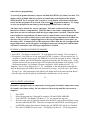
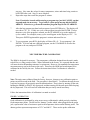
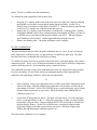
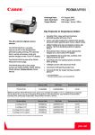
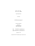
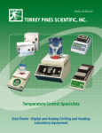
OPERATING MANUAL
EchoThermJ
PROGRAMMABLE
DIGITAL HOT PLATE/STIRRER
MODEL HS40
DOCUMENT NUMBER HS40-01
TORREY PINES SCIENTIFIC, INC.
1784 LA COSTA MEADOWS DRIVE
SAN MARCOS, CA 92069
TELEPHONE: (760)-471-9100
FAX: (760)-471-9310
E-MAIL: [email protected]
WEB SITE: www.torreypinesscientific.com
TABLE OF CONTENTS
PAGE
I.
INTRODUCTION
3
II.
WARRANTY
3
III.
RETURN OF ITEMS
3
IV.
LABELS
3
V.
CAUTIONS
4
VI.
GENERAL DESCRIPTION
5
VII.
FRONT AND REAR PANEL CONTROLS
6,7
VIII.
SET UP INSTRUCTIONS
8
IX.
DISPLAY AND KEYBOARD DESCRIPTION
9,10
X
SIMPLE OPERATIONS
11
XI.
SIMPLE TEMPERATURE, RAMP RATE, STIRRER,
TIMER, AND AUTO-OFF SETTINGS
11,12
XII
PROGRAM OPERATIONS
13,14
XIII
TEMPERATURE CALIBRATION
14,15.16
XIV
POWER INTERRUPTION PROTECTION
16
XV.
RS232 INTERFACE
16,17,18
XVI. CLEANING, MAINTENANCE, AND CONSUMABLE PARTS
18,19
XVII. ADDITIONAL SYMBOLS
19
2
I. INTRODUCTION
Congratulations on your purchase of an EchoThermJ Programmable Digital Hot Plate/ Stirrer.
Please read the instructions carefully to insure that you receive the maximum benefit from it.
Also, be sure to fill out and return the enclosed warranty registration card.
II. WARRANTY
Torrey Pines Scientific warrants this product to be free from defects in material and
workmanship for a period of one year from the date of purchase. If repair or adjustment is
necessary and has not been the result of abuse or misuse within the one year period, please
return---freight prepaid--and correction of the defect will be made without charge.
Out-of-warranty products will be repaired on a charge basis.
III. RETURN OF ITEMS
Authorization must be obtained from our Customer Service Department before returning
items for any reason. When applying for authorization, please include data regarding the
reason the items are to be returned. For your protection, items must be carefully packed to
prevent damage in shipment and insured against possible damage or loss. Torrey Pines
Scientific will not be responsible for damage resulting from careless or insufficient packing. A
15% restocking charge will be made on all unauthorized returns.
NOTE: Torrey Pines Scientific reserves the right to make improvements in design, construction,
and appearance without notice.
IV. LABELS
There are various labels on the body of this unit. Listed below are the labels and their meanings.
This symbol means: Attention. The instruction manual is to be consulted for
further information. Attention: Lire ce manuel pour des informations
complémentaries.
This symbol means: Warning. Hot surface. Attention, surface chaude.
This symbol means: Ground or earth connection. Connexion á la terre.
3
V. CAUTIONS
HEATER PLATE SURFACE
The Torrey Pines Scientific HS40 Programmable Hot Plate/Stirrer is capable of temperatures in
excess of 450EC at the plate surface. Touching the heated surface will cause severe burns. USE
EXTREME CAUTION AT ALL TIMES. Never leave your hot plate accessible to others
while it is hot. Although the unit is equipped with a AHOT WARNING@ indicator on the front
panel, do not rely on this alone. It si good practice to never touch the heater surface.
NOTE: DO NOT INSTALL THIS UNIT CLOSER THAN SIX (6) INCHES (15.24 CM)
TO A WALL OF COMBUSTIBLE MATERIAL. ALSO, THIS UNIT IS NOT FOR USE
WITH FLAMMABLE SUBSTANCES.
TEMPERATURE PROBE
When attempting to control PROBE TEMPERATURE, plug in the temperature probe and place
it in the sample AT ALL TIMES. If not placed into the sample and plugged into the rear of the
hot plate, the unit will not be able to sense the temperature of the sample as heat is being applied.
This will result in driving the heater to its maximum and could result in ruining the sample.
Temperature probes vary in size and material. The most commonly used probe is the stainless
steel 6-inch immersion probe ( part number HS30-600). For other probes available in other
lengths and materials, call the factory or consult your price list. All probes come with 3-foot
(91.44 cm) interconnect cable and are 3/16th (47.6 mm) in diameter. Stainless steel probes work
best with all but the most aggressive chemicals. Solid Teflon will work with the most aggressive
chemicals, but only to about 260EC. Glass probes are available for use with aggressive
chemicals at higher temperatures.
ELECTRICAL
These hot plate/stirrers are made in models that operate at 100, 115, and 230 volts AC "10%. Be
certain that your voltage matches the unit you receive. Check the nameplate on the bottom for
the voltage setting on your unit. Be certain to use a three-wire, properly grounded AC input.
Take the normal care and precaution one would use with any electrical appliance. Be careful to
keep the AC line cord away from the hot plate. Be certain to use a line cord of the same type
and rating as the one supplied with this unit. Note: all fuses are fast blow. They are rated
at 8 amps, 125 volts for ceramic topped 100 and 115 VAC units, and 4 amps, 250 volts for
230 VAC units. Cast aluminum topped units are 8 amps, 125 volts for 100 and 115 VAC
units and 4 amps, 250 volts for 230 VAC units.
Bien vérifier que le cordon utilisé est du même type que celui livré avec l=unité. Note: tous les
fusibles sont à action rapide. Lis sont à 8 A et 125 volts pour les unités á surface céramique de
100 et 115 volts et de 4A pour les unité de 250 et 230 volts. Pour les unités à boîtier en
aluminum de 100 et 115 volts, l=ampérage est de 8A pour les fusibles. Pour les modèles en 250
et 230 volts, il est de 4A.
4
VI. GENERAL DESCRIPTION
The Torrey Pines Scientific HS40 Series Programmable Hot Plate/Stirrer is a general purpose
digital hot plate/stirrer. It is available with a solid ceramic top only. The top is 8" x 8" (20.32
cm x 20.32 cm) in size. All functions are settable from the digital front panel and display.
HEATER
Either the plate surface temperature or the actual sample temperature may be set. A sensor in the
plate is used to monitor surface temperature, or, alternately, a 100-ohm, 3-wire, platinum RTD
temperature probe may be connected to the rear of the unit and inserted into the sample to
measure sample temperature. When a temperature is set, power is applied to the heater to
precisely control the temperature at the plate surface or at the sample, as directed by the user.
An optional Aramp value@ may be entered into the unit which causes the temperature to approach
the target value at a controlled rate of temperature change. This can be either an increase or
decrease in temperature. Temperature is always displayed in degrees centigrade.
TIMER
The H430 comes with a count down timer that is settable and displays in hours, minutes and
seconds. The timer can be set to 99:59:59 hours. When the timer is set it starts to count down to
zero. At zero the timer will sound an audible alarm that will ring five times. In addition to the
timer, the unit has an AUTO-OFF function. When the AUTO-OFF function is activated the
heater and stirrer will turn off at the end of any count down timer setting.
ALARMS
In addition to the audible alarm associated with the count down timer, the HS40 has an over
temperature alarm that activates at 455EC. If, for any reason, the set temperature runs away
and exceeds 455EC, the HS40 will turn on the over temperature alarm LED, sound an audible
alarm, and shut the heater off. If or when the heater plate surface cools to below 450EC, the
heater will turn on again, and the alarm LED and audible alarm will turn off. In addition, all
circuitry in the unit is backed up by a separate watchdog circuit to assure safety.
NOTE: Failing to place the temperature probe in the solution and then setting a probe
temperature will cause the heater to heat to over 455EC and set off the OVER
TEMPERATURE ALARM. Also, the OVER TEMPERATURE ALARM may come on if a
very large sample is placed on the unit and a probe temperature is set. This setting can
cause the heater surface to go over 455EC to achieve the probe temperature set to heat the
large sample.
STIRRER
The stirrer is a motor driven magnet which revolves directly under the center of the heater plate.
It is normal to stir a solution while heating. A stir bar is used in the solution and couples with
the motor driven magnet and stirs the solution.
5
VII. FRONT AND REAR PANEL CONTROLS
FRONT PANEL
Shown above are the keyboard and display for the HS40 Programmable Digital Hot Plate/Stirrer.
The front panel has a tactile touch membrane keyboard with audible feedback. The keyboard is
used to set all operating parameters. The display is a LCD type made up of five rows of numbers
and several icons which function to display all parameters when the unit is running and during
setting. When the unit is turned on, the display will come on and show the actual plate surface
temperature. If a probe is used, it will display the probe temperature as well. The timer, stirrer
and ramp functions will show zeros.
There are two LED=s on the front panel as well. One is actuated when the plate surface goes
over 50EC to remind the user that the plate surface is hot enough to cause burns. The second is
for the over temperature alarm.
A thin plastic membrane cover which fits over the front panel is supplied with the unit to protect
it from dust, dirt and possible chemical spills. The keyboard can be operated with the membrane
cover in place. Replacement covers are available.
6
REAR PANEL
The AC power connector jack, fuse holder and switch are a module mounted on the right rear of
the unit. The temperature probe jack is mounted to the right. Note the polarity on the probe
jack. Be sure not to force this connection when plugging in the temperature probe.
The AC power jack is a three-prong, male plug combining the snap-in fuse holder and AC
switch. The fuse types used appear on the label on the rear of the unit. Both neutral and high
lines are fused.
CAUTION: If the fuses blow repeatedly, contact your dealer or the manufacturer.
ATTENTION: Si les fusibles sautent de manière répétitive, contacter votre distributeur
habituel ou le fabricant.
The temperature sensor jack is a 3-pin DIN jack which is used with a 100-ohm at 0EC platinum
RTD temperature probe.
7
VIII. SET UP PARAMETERS AND INSTRUCTIONS
The HS40 Programmable Digital Hot Plate/Stirrer is a very simple instrument to use. Follow the
instructions below.
SET UP PARAMETERS
1. Ambient operating temperature range is from 5EC to 40EC.
2. Maximum altitude of operation should not exceed 2000 meters.
3. Maximum ambient operating relative humidity should not exceed 80% at 31EC decreasing
linearly to 50% relative humidity at 40EC.
SET UP INSTRUCTIONS
1. Place the unit on a level, dry bench or surface.
2. Plug the unit into a properly grounded, three-wire outlet of proper voltage.
3. Plug the temperature probe (if used) into the jack on the rear of the unit.
4. Place the sample on the heater plate and put the temperature probe (if used) into the sample
container.
5. Turn on the unit by the switch on the rear panel. The unit will beep once and the display will
light up. At this point the user can set or view any of the parameters of the unit.
6. Set either plate or probe target temperature, stirrer, timer, ramp rate, or program according to
the instructions given in the following sections.
Note: Do not use this equipment in any manner not specified by the manufacturer.
Note: Ne pas utiliser cet équipement si vous ne pouves pas respecter les conditions
d=utilisation spécifiées par le fabricant.
ENVIRONMENTAL INFORMATION
1. This unit is for installation category II.
2. This unit is rated pollution degree 2.
8
IX. DISPLAY AND KEYBOARD DESCRIPTIONS
DISPLAY
The display has five rows of numbers and icons. From the top they are as follows.
Probe Temperature: The icon to the left of the numbers represents a probe in a solution. This
row of numbers shows the probe temperature. These numbers will always be followed with a
AC@ which denotes that the temperature reading is in degrees centigrade. The small AT@ and AA@
following that tells the user that the numbers displayed are the actual temperature of the probe in
the solution or the target temperature as set by the user. These two letters will toggle between
TARGET(T) and ACTUAL(A), and the numbers in the display will change accordingly to show
the progress of a set temperature toward its target. If no target temperature is set, then the
display will always show the actual probe temperature.
Plate Temperature: The icon to the left of the second row of numbers represents the plate
temperature at its surface as measured with a sensor in the heater plate. The row of numbers to
the right of the icon shows the plate surface temperature. These numbers also are followed by a
AC@ which denotes that the temperature reading is in degrees centigrade. The small AT@ and AA@
following that tells the user that the numbers displayed are the TARGET(T) or ACTUAL(A)
plate surface temperatures. If no plate surface target temperature is set, the AT@ and AA@ will not
toggle. However, the actual plate temperature will be displayed even when a probe temperature
has been set.
Stirrer: The icon next in line down the display looks like a propeller and is the STIRRER icon.
The row of numbers to the right of the icon displays the actual stirrer speed as set by the user. It
is in RPM (revolutions per minute).
Ramp: The icon next in line down the display looks like a staircase and is the RAMP icon. The
number value set in the display is always in degrees centigrade per hour. This tells the user that
the target temperature as set for the probe or plate is moving from its starting point to the target
temperature at a fixed rate in degrees centigrade per hour.
Timer: The next icon down the display is the hourglass icon that represents the timer function.
The numbers that can be set and displayed next to the icon are in hours, minutes, and seconds.
The timer can be set to 99:59:59 maximum. The timer will count down to zero from its setting
and sound an audible alarm and then start to count up letting the user know how long it has been
since the timed counted down to zero. The words AAUTO-OFF@ next to the numbers are visible
only when the AUTO-OFF function is actuated. When this function is actuated, the timer will
count down to zero, sound the audible alarm, and turn the heater and stirrer off. In addition, the
Timer numbers are used in writing a program, and in displaying program steps and cycles as the
program progresses. More on writing and running programs later in the manual.
9
KEYBOARD
Up/Down Arrows: The UP and DOWN arrows in the center of the keyboard are used to set
values for the probe temperature, plate temperature, stirrer, ramp, timer, and progressing within
the steps of a program when writing or editing the program. Pushing and holding the UP arrow
will cause the display parameter as selected to scroll up in value. Pushing and holding the
DOWN arrow will cause the display parameter as selected to go down in value. In addition, the
DOWN arrow is used as Acancel@ to turn off the beep when the timer counts down.
Probe Temperature Icon: The probe temperature icon is the one that matches the icon to the left
of the top line of the display. Touching and releasing this icon selects the UP and DOWN
arrows to set the PROBE TEMPERATURE.
Plate Temperature Icon: The plate temperature icon is the one that matches the second line down
from the top in the display. Touching and releasing this icon selects the UP and DOWN arrows
to set the PLATE TEMPERATURE.
Stirrer Icon: The stirrer icon matches the third line down from the top of the display. Touching
and releasing this icon selects the UP and DOWN arrows to set the STIRRER value.
Ramp Icon: The ramp icon is the one that matches the fourth line down from the top of the
display. Touching and releasing this icon selects the UP and DOWN arrows to set the ramp
value.
Timer Icon: The timer icon is the one that matches the last line at the bottom of the display.
Touching and releasing this icon selects the UP and DOWN arrows to set the TIMER value.
Auto-Off Key: Touching and releasing this key activates the AUTO-OFF function. When
activated, this will shut off the heater and stirrer when the timer counts down to zero. This
function can be turned on or off by touching the AUTO-OFF button at any time during a timed
event. When activated, the words AAUTO-OFF@ will be illuminated on the display.
Heat Off Key: Touching and releasing the HEAT OFF key will turn off the heater.
Stir Off Key: Touching and releasing the STIR OFF key will turn off the stirrer.
Edit Key: The EDIT key is used to enter the program memory to either write or edit a program.
Cancel Key: The Cancel key is used to cancel a program step while writing or editing a program.
Run Key: The Run key is used to start running a program in memory.
Enter Key: The Enter Key is used to enter a value into a program.
10
X. SIMPLE OPERATION
The HS40 is a fully programmable digital stirring hot plate. With it the user has the ability to
write and store in memory ten programs of as many as ten steps each for instant recall and later
use. Also, the unit can be used to set a single temperature, temperature ramp, stirring speed and
timer function without going into the memory of the unit. The memory should be used to store
complex routines where all the parameters of the sample can be changed automatically to other
parameters without user attention.
XI. SIMPLE TEMPERATURE, RAMP RATE,STIRRER,
TIMER, AND AUTO-OFF SETTINGS
TEMPERATURE
The heater may be set to control either the plate surface or the sample itself. This is done by
entering a Atarget@ temperature from the front panel keyboard. The control electronics in the hot
plate will automatically apply power to the heater plate to reach the desired temperature.
The user may enter either a target probe temperature or a target plate temperature. Only one
target temperature is allowed at one time. Setting a target probe temperature will erase any
target plate temperature previously set and vice versa.
Target temperatures may be set anywhere in the range from ambient to 450EC .
Setting Solution Temperature: To set a solution temperature, touch and release the solution
temperature icon. Next, touch the UP arrow until the display (top row) shows the temperature
wanted. If the target is overshot while setting, push the DOWN arrow until the correct value is
in the display. The unit will now turn the heater on and drive the solution to the target
temperature. Note that the solution display will toggle between the TARGET (T) and the
ACTUAL (A) temperatures. When the target temperature is reached, the AT@ and AA@ will
alternate but the numerical value will remain the same.
CAUTION: Be certain the temperature probe is in the solution and plugged into the rear
panel jack when a solution temperature target has been entered. Failure to do so could
damage your sample because the hot plate will drive to maximum while seeking a
temperature it cannot find.
PRÉCAUTION D= EMPLOI: Bien vérifier que la sonde de température plonge dans le
liquide et qu=elle est connectée dans la fiche située à l=arrière de l=appareil lorsque vous
sélectionnez une température. L=échantillon risque d=être endommagé si la sonde n=est pas
connectée car la plaque va monter au maximum de sa température en recherchant une
température qui n=aura pas été.
11
Setting Plate Temperature: To set a plate temperature, touch and release the plate temperature
icon. Next, press the UP arrow until the display (second row) shows the temperature wanted. If
the target is overshot while setting, push the DOWN arrow until the correct value is in the
display. The unit will now turn on the heater and drive the plate to the target temperature
selected. Note that the display will toggle between the TARGET (T) and ACTUAL (A)
temperature. Again, when the target temperature is reached, the AT@ and AA@ will alternate but
the numerical value displayed will remain the same.
Note: When a heater value is turned off, the value is saved so that when the heater is next
used that previously set value is displayed and set. To change that value use the Up or
Down arrows.
Setting Ramp: NOTE: IF A RAMP VALUE IS TO BE USED, THE RAMP VALUE MUST
ALWAYS BE SET BEFORE SETTING A TARGET TEMPERATURE. To set a ramp
value, touch and release the ramp icon. Press the UP arrow until the display (fourth row) shows
the value desired. Remember. The ramp value is always in degrees centigrade per hour. The
heater will now go from its current value to the target temperature, either plate or solution, at the
rate just instructed.
It is valuable to note that the ramp can be set to go up to a target temperature or down from a
higher temperature to a lower one. However, the unit can never ramp down any faster than the
sample can cool naturally. When ramping down, the heater is used to slow a cooling rate only.
Setting Stirrer: To set a stirrer speed, touch and release the stirrer icon. Press the UP arrow until
the display (third row) shows the value desired. The numbers shown are in revolutions per
minute (rpm). The stirrer will now go to the value instructed.
Setting Timer: To set a timer value, touch and release the timer icon (hourglass). That icon will
now flash in the display. Note that the seconds digits in the display will flash. Seconds can now
be set if wanted by pressing the UP arrow. To set minutes, press the timer icon again. Note that
the minute digits will now flash. Minutes can now be set by touching the UP arrow. To set
hours, press the timer icon again and the hours digits will flash. Hours can now be set by
touching the UP arrow. If only seconds or minutes are set, continue to press the timer icon until
it scrolls past hours. Touching the timer icon again will start the timer. When the Timer counts
down to zero it will alarm 5 times and start to count up. The up counter lets the user know how
long it has been since the Timer counted to zero. To stop the timer from counting up, touch the
DOWN arrow.
Setting Auto-Off: To set the auto-off function, touch and release the AUTO-OFF button. The
display will illuminate the words AAUTO-OFF@ to the right of the timer. This tells the user that
the auto-off function is set. To turn off the auto-off function, touch the AUTO-OFF button
again. The words, AAUTO-OFF@ will no longer be illuminated in the display. Remember, when
AUTO-OFF is on, the unit will automatically turn off the heater and stirrer when the timer
counts down to zero. The user does not have to be present to turn off the heater or stirrer when it
is in this mode.
12
XII. PROGRAMMABLE OPERATION
The HS40 has the ability to store ten programs in memory for instant recall and use at any time.
Each program has ten steps maximum where one step is a temperature, stirring speed, ramp
function (if wanted), and time. At the end of each program there is a cycle step that can be
selected which will repeat the program up to 98 times. Setting the cycles to 99 makes the
program repeat infinitely. These programs are stored in CMOS and cannot be lost by a power
failure or by turning the unit off. However, if power fails during a program run, when power
returns, the unit will have lost its instructions and will be sitting with the same information on
the display as when the unit was first turned on. To stop and program while it is running touch
CANCEL.
Some rules for programming:
To erase all programs in memory, depress and hold the EDIT key for about 5 seconds. The
display will be all blank with the exception of 4 small lines at the bottom of the display.
When the EDIT key is released, after a second or so, the display will return to the normal
screen and the programs will be erased. This erases ALL programs in memory. To change
or erase one program the user must go into the program and remove each step.
The timer can be used in two ways in a program. The timer can be used with a ramp
function or without a ramp function. When the timer is used with a ramp function, the
timer does not start to count down until the target temperature is reached. When the timer
is used without a ramp function, the timer starts to count down as soon as the program
starts. If the user wants a timed event to start after the target temperature is reached, but
does not want to wait for a ramped approach to the target temperature to take place, set
the ramp to 450. In almost all cases, this ramp rate is faster than the unit can approach the
target temperature, and it will appear as though no ramp rate is being used, and the timer
will start to count down after the target temperature is reached.
RUNNING A PROGRAM STORED IN MEMORY
1. Press RUN. The display will show PR 01 at the bottom of the display. This is program 1.
2. If program 1 is the choice to be run, next press ENTER. Program 1 will now start to run. If
program 1 is not the choice use the UP ARROW to scroll to the program of choice. When the
program is chosen, press ENTER and the program stored in that site will start to run. As the
program starts to run, the program steps will be displayed at the bottom of the display as will
the program number. For example: Program 1 and step 2 will be displayed as 01 02.
Program 1 step 5 will be displayed as 01 05. In addition, as the unit progresses through the
steps in the program, the audible alarm will sound once for step 1, twice for step 2, three times
for step 3, etc. This bottom line of the display will change back to the timer function shortly
after the step is reached, displayed, and alarmed so that the timer can be viewed.
13
HOW TO WRITE A PROGRAM
Remember, a program step is a temperature, stirring speed (if wanted), temperature ramp
(if wanted), and a timer setting. Do not advance to the next step until the current one is
complete.
1
2
3
4
5
Press EDIT
Select the program site (1 through 10) using the UP and DOWN ARROWS.
Touch ENTER. The display will show 01 01, for program one step one.
Enter the ramp value if wanted (remember how the timer works with and without a ramp
function) and touch ENTER. Then enter a temperature and ENTER, and stirring speed
and ENTER, and the time function for that step and ENTER. This step is now finished.
Press the UP ARROW to go to step 2. The display will show 01 02 for program one
6
step two. Now enter the values for ramp, temperature, stirrer and timer being certain to
hit ENTER after each. Step 2 is now complete.
Repeat the steps above until the program is written.
Note: If a mistake is made while entering a program step, just hit CANCEL on that
step and make the new entry. To go back to a prior program step, hit the DOWN
ARROW. Likewise, to go forward to another program step, hit the UP ARROW.
7
After the last program step data has been entered, press ENTER twice. The display will
now show CYC 01. If only one cycle of the program is needed, hit ENTER. If more
than one cycle of the program is wanted, use the UP ARROW to go to the number of
cycles wanted. For example, twenty cycles would appear on the display as CYC 20.
Then press ENTER again and the program is written and stored for use.
8
To run a program, press RUN, the display will show PR 01. To run program 1, hit
ENTER. To select and run a different program, use the UP ARROW to scroll to the
program to be run, and press ENTER.
XIII. TEMPERATURE CALIBRATION
The HS40 is designed for accuracy. The temperature calibration designed into the unit is made
to hold for very long periods of time. When calibrated in the factory, it is expected that the unit
will meet the most demanding customers= requirements. However, our standards for temperature
measurement may not be the same as the users. Therefore, the HS40 has been designed to be
calibrated in the field by the user. Follow the instructions below if calibration is wanted or
needed.
14
Note: The units come calibrated from the factory, however, changes to any calibration point or
points can still be made in the field. The procedure is listed below. To calibrate the unit the user
is advised to remove all previously entered calibration data. That is done by turning off the unit,
holding the PROBE or PLATE key depressed, and then turning ON the unit again while keeping
the key depressed. This will erase all calibration data previously stored in memory.
Follow the instructions below if calibration is wanted or needed.
PROBE CALIBRATION
Probe calibration is performed by using an accessory calibration kit which precisely simulates
fixed temperature points. The kit has two Adummy@ probes which, when plugged into the probe
jack, represent the value of resistance equal to the temperature shown on the dummy probe. The
dummy probes represent temperatures of 25EC and 400EC. These are the probe calibration
points. The kit is available from the manufacturer.
To calibrate the probe temperature follow these steps.
1.
2.
3.
Insert the 25EC dummy probe in the probe jack at the rear of the unit. Depress and hold
the PROBE icon for three seconds and the probe display will flash. Use the UP or
DOWN arrow as needed to set the display to read 25EC. When the display stops flashing
it will read 25EC and the low calibration point has been set.
Remove the 25EC dummy probe and replace it with the 400EC dummy probe. Depress
and hold the PROBE icon for three seconds and the probe display will flash. Use the UP
or DOWN arrow as needed to make the probe display read 400EC. When the display
stops flashing it will read 400EC and the high calibration point has been set.
Remove the dummy probe. The probe calibration is now complete.
PLATE CALIBRATION
The plate calibration does not affect the probe calibration and vice versa. If you are using the
probe temperature control loop only, it is not necessary to calibrate the plate loop. The plate
loop has been factory calibrated and is not likely to change.
To calibrate the plate, one needs an accurate temperature meter, preferably digital, and a surface
temperature probe. This is a very difficult measurement to make, and not all surface temperature
probes will do the job well. If you need help, please contact the factory.
The calibration procedure requires that calibration starts at the low temperatures and goes high.
It is time consuming. Be sure before making an adjustment that the plate temperature has
stabilized at the point being calibrated. Follow the procedure below.
15
1.
Start at ambient. Using your temperature meter, read the plate surface temperature in the
center of the plate. Push and hold the plate temperature icon for three seconds and the
plate display will flash. Use the UP or DOWN arrows to make the display agree with the
measured plate temperature on your meter. When the display stops flashing the low
calibration point is set.
2.
Set the PLATE temperature to 400EC. The plate will start to heat. Give the unit ample
time to reach and stabilize at 400EC. When the temperature is stable, measure the plate
temperature with your meter. Depress and hold the PLATE icon for three seconds until
the plate display flashes. Use the UP or DOWN arrow as needed to make the plate
temperature display read what is measured on your meter. When the display stops
flashing the high temperature calibration point is set.
The plate surface calibration is now complete.
XIV. POWER INTERRUPTION PROTECTION
The unit is provided with power interruption protection. If AC power is interrupted while
running a temperature, the unit will go back to the set temperature when power returns. To let
the user know that a power interruption has occurred, the temperature display will be flashing
between TARGET(T) and ACTUAL(A) faster than usual by only dwelling for one second on
each. Under normal operating conditions, the display will alternate between (T) and (A)
dwelling on (A) for three seconds and (T) for one second. To restore the display to normal,
touch the DOWN arrow.
XV. RS232 INTERFACE
Note that not all units are supplied with this feature. It is available as a factory installed
accessory at the time of order. Adding it later can be done at the factory or by a qualified
technician in the field.
The RS232 is available through the 9-pin D-subminiature connector on the rear of the unit. It
operates at 2400 Baud, 8 Data Bits, 1 Stop Bit, No Parity. No handshake hardware or software is
necessary. It will work well on a Windows terminal program per the settings listed here. All
communications settings and queries are done using ASCII characters with carriage return as the
terminating character (CRo).
Any serial port on your PC can be used. The pin outs follow standards for RS232C. On the
connector, pin 5 is ground, pin 3 is RX and pin 2 is TX. We do not provide software for this
application, however, several users have found that using Windows Terminal Program, and
Visual Basic works well, but any programming language can be used.
16
Note: To comply with CE and to avoid possible EMI radiation from the RS232 cable, you
should use a shielded cable.
Query
Request current plate temperature
Request current probe temperature
Request current timer
Request ramping value
Request plate target temperature
Request target probe temperature
Request stirrer target speed (rpm)
Command
a
b
c
d
e
f
g
For example: To request current plate temperature one needs to send two characters
a + CR
and the unit responds xxx + CR where xxx is the present temperature of the heater plate.
NOTE: If there is no target plate temperature set into the unit it will send A---@ + CR.
Set
Plate target temperature
Probe target temperature
Timer
Ramping
Stirrer speed (rpm)
Stirrer Off
Heater Off
Toggle Auto On/Off
Command
A
B
C
D
E
F
G
H
For example: To set the following command string do the following:
To set the plate temperature target to 123EC
A 123 + CR
To set the timer
C 12:34:5600 + CR
17
To set stirrer speed to 500 rpm
E 500 + CR
Note: If the command string is valid, the unit will respond back with the message ACommand
OK@ + CR. If the command is incorrect the message will be ACommand Failed@ + CR.
XVI. CLEANING, MAINTENANCE, AND CONSUMABLE PARTS
Cleaning
This unit is subject to splashes and spills during normal use. Be sure to clean all spills quickly.
Wipe spills with a soft cloth or paper towel. If a cleaning solution is necessary, use a mild soap
or detergent solution and a soft cloth. Be sure not to use solvents. They could damage the paint,
labels or display window on the unit. A mild abrasive can be used to clean the ceramic glass
heater surface. Do not use abrasives on the cast aluminum heater top. It will scratch the surface.
CAUTION: Do not attempt to clean the heater surface when it is hot. Burns could occur.
PRÉCAUTION D=EMPLOI: Ne pas nettoyer la surface de la plaque lorqu=elle est chaude
pour éviter toute brûlure accidentelle.
Maintenance
There is no ongoing maintenance program needed with this unit other than the normal care and
cleaning as instructed above, and a simple inspection done whenever the unit is to be used. This
simple inspection should include:
1- Checking that the AC line cord is not frayed or burned.
2- Checking that the unit is not dirty to a point where proper performance is impaired. This is
especially important relative to the membrane switch and LCD window.
3- Being certain to store the unit properly, when not in use, in an area that will not have items
placed on top of the unit, and covered in a way that will keep dirt and other foreign bodies out
of the unit.
18
Spare and Consumable Parts
There are very few spare or consumable parts necessary. A simple list with part number is
below.
Part Number
HS30-710
730-0001
730-0006
730-0008
730-0004
730-0005
380-0003
380-0004
380-0005
Description
Replacement Keyboard Covers
Power Cord, US
Power Cord, German (European)
Power Cord, UK
Power Cord, Italian
Power Cord, Australian
Fuse, 8 amp, 125 volt
Fuse, 10 amp, 125 volt
Fuse, 4 amp, 250 volt
XVII. ADDITIONAL SYMBOLS
The following are additional symbols found on the labels of the instrument.
Symbol
Description
V
~
A
Hz
W
F
T
I
O
Voltage
Alternating Current
Current
Frequency
Power
Fast Acting Fuse
Time Delay Fuse
Mains On
Mains Off
19