1
MELSEC iQ-R Simple Motion Module
User's Manual (Application)
RD77MS2
RD77MS4
RD77MS8
RD77MS16
SAFETY PRECAUTIONS
(Read these precautions before using this product.)
Before using this product, please read this manual and the relevant manuals carefully and pay full attention to safety to handle
the product correctly.
The precautions given in this manual are concerned with this product only. Refer to the user's manual of the CPU module to
use for a description of the PLC system safety precautions.
In this manual, the safety precautions are classified into two levels: "
WARNING" and "
CAUTION".
WARNING
Indicates that incorrect handling may cause hazardous conditions, resulting in
death or severe injury.
CAUTION
Indicates that incorrect handling may cause hazardous conditions, resulting in
minor or moderate injury or property damage.
Under some circumstances, failure to observe the precautions given under "
CAUTION" may lead to serious
consequences.
Observe the precautions of both levels because they are important for personal and system safety.
Make sure that the end users read this manual and then keep the manual in a safe place for future reference.
[Design Precautions]
WARNING
● Configure safety circuits external to the programmable controller to ensure that the entire system
operates safely even when a fault occurs in the external power supply or the programmable controller.
Failure to do so may result in an accident due to an incorrect output or malfunction.
(1) Configure external safety circuits, such as an emergency stop circuit, protection circuit, and
protective interlock circuit for forward/reverse operation or upper/lower limit positioning.
(2) The programmable controller stops its operation upon detection of the following status, and the
output status of the system will be as shown below.
• Turned off if the overcurrent or overvoltage protection of the power supply module is activated.
• Held or turned off according to the parameter setting if the self-diagnostic function of the CPU
module detects an error such as a watchdog timer error.
(3) Also, all outputs may be turned on if an error occurs in a part, such as an I/O control part, where
the CPU module cannot detect any error. To ensure safety operation in such a case, provide a
safety mechanism or a fail-safe circuit external to the programmable controller. For a fail-safe
circuit example, refer to the user's manual of the CPU module to use.
(4) Outputs may remain on or off due to a failure of a component such as a relay and transistor in an
output circuit. Configure an external circuit for monitoring output signals that could cause a
serious accident.
● In an output circuit, when a load current exceeding the rated current or an overcurrent caused by a
load short-circuit flows for a long time, it may cause smoke and fire. To prevent this, configure an
external safety circuit, such as a fuse.
● Configure a circuit so that the programmable controller is turned on first and then the external power
supply. If the external power supply is turned on first, an accident may occur due to an incorrect output
or malfunction.
● For the operating status of each station after a communication failure, refer to manuals relevant to the
network. Incorrect output or malfunction due to a communication failure may result in an accident.
1
WARNING
● When connecting an external device with a CPU module or intelligent function module to modify data
of a running programmable controller, configure an interlock circuit in the program to ensure that the
entire system will always operate safely. For other forms of control (such as program modification,
parameter change, forced output, or operating status change) of a running programmable controller,
read the relevant manuals carefully and ensure that the operation is safe before proceeding. Improper
operation may damage machines or cause accidents.
● Especially, when a remote programmable controller is controlled by an external device, immediate
action cannot be taken if a problem occurs in the programmable controller due to a communication
failure. To prevent this, configure an interlock circuit in the program, and determine corrective actions
to be taken between the external device and CPU module in case of a communication failure.
● Do not write any data to the "system area" and "write-protect area" of the buffer memory in the
module. Also, do not use any "use prohibited" signals as an output signal from the CPU module to
each module. Doing so may cause malfunction of the programmable controller system. For the
"system area", "write-protect area", and the "use prohibited" signals, refer to the user's manual for the
module used.
● If a communication cable is disconnected, the network may be unstable, resulting in a communication
failure of multiple stations. Configure an interlock circuit in the program to ensure that the entire
system will always operate safely even if communications fail. Failure to do so may result in an
accident due to an incorrect output or malfunction.
● To maintain the safety of the programmable controller system against unauthorized access from
external devices via the network, take appropriate measures. To maintain the safety against
unauthorized access via the Internet, take measures such as installing a firewall.
● Configure safety circuits external to the programmable controller to ensure that the entire system
operates safely even when a fault occurs in the external power supply or the programmable controller.
Failure to do so may result in an accident due to an incorrect output or malfunction.
(1) Machine home position return is controlled by two kinds of data: a home position return direction
and a home position return speed. Deceleration starts when the near-point dog signal turns on. If
an incorrect home position return direction is set, motion control may continue without
deceleration. To prevent machine damage caused by this, configure an interlock circuit external to
the programmable controller.
(2) When the module detects an error, the motion slows down and stops or the motion suddenly
stops, depending on the stop group setting in parameter. Set the parameter to meet the
specifications of a positioning control system. In addition, set the home position return parameter
and positioning data within the specified setting range.
(3) Outputs may remain on or off, or become undefined due to a failure of a component such as an
insulation element and transistor in an output circuit, where the module cannot detect any error. In
a system that the incorrect output could cause a serious accident, configure an external circuit for
monitoring output signals.
● If safety standards (ex., robot safety rules, etc.,) apply to the system using the module, servo amplifier
and servomotor, make sure that the safety standards are satisfied.
● Construct a safety circuit externally of the module or servo amplifier if the abnormal operation of the
module or servo amplifier differs from the safety directive operation in the system.
● Do not remove the SSCNET cable while turning on the control circuit power supply of Multiple CPU
system and servo amplifier. Do not see directly the light generated from SSCNET connector of the
module or servo amplifier and the end of SSCNET cable. When the light gets into eyes, you may
feel something wrong with eyes. (The light source of SSCNET complies with class1 defined in
JISC6802 or IEC60825-1.)
2
[Design Precautions]
CAUTION
● Do not install the control lines or communication cables together with the main circuit lines or power
cables. Keep a distance of 100 mm or more between them. Failure to do so may result in malfunction
due to noise.
● During control of an inductive load such as a lamp, heater, or solenoid valve, a large current
(approximately ten times greater than normal) may flow when the output is turned from off to on.
Therefore, use a module that has a sufficient current rating.
● After the CPU module is powered on or is reset, the time taken to enter the RUN status varies
depending on the system configuration, parameter settings, and/or program size. Design circuits so
that the entire system will always operate safely, regardless of the time.
● Do not power off the programmable controller or do not reset the CPU module during the setting
registration. Doing so will make the data in the flash ROM undefined. The data need to be set in the
buffer memory and to be written to the flash ROM again. Doing so may cause malfunction or failure of
the module.
● Reset the CPU module after changing the parameters. Failure to do so may cause malfunction
because the previous parameter settings remain in the module.
● When changing the operating status of the CPU module from external devices (such as remote RUN/
STOP), select "Do Not Open by Program" for "Opening Method" in the module parameters. If "Open
by Program" is selected, an execution of remote STOP causes the communication line to close.
Consequently, the CPU module cannot reopen the communication line, and external devices cannot
execute the remote RUN.
3
[Installation Precautions]
WARNING
● Shut off the external power supply (all phases) used in the system before mounting or removing the
module. Failure to do so may result in electric shock or cause the module to fail or malfunction.
[Installation Precautions]
CAUTION
● Use the programmable controller in an environment that meets the general specifications in the
manual "Safety Guidelines" included in the base unit. Failure to do so may result in electric shock, fire,
malfunction, or damage to or deterioration of the product.
● To mount a module, place the concave part(s) located at the bottom onto the guide(s) of the base unit,
and push in the module until the hook(s) located at the top snaps into place. Incorrect mounting may
cause malfunction, failure, or drop of the module.
● When using the programmable controller in an environment of frequent vibrations, fix the module with
a screw.
● Tighten the screws within the specified torque range. Undertightening can cause drop of the screw,
short circuit, or malfunction. Overtightening can damage the screw and/or module, resulting in drop,
short circuit, or malfunction.
● When using an extension cable, connect it to the extension cable connector of the base unit securely.
Check the connection for looseness. Poor contact may cause incorrect input or output.
● When using an SD memory card, fully insert it into the memory card slot. Check that it is inserted
completely. Poor contact may cause malfunction.
● Securely insert an extended SRAM cassette into the cassette connector of a CPU module. After
insertion, close the cassette cover and check that the cassette is inserted completely. Poor contact
may cause malfunction.
● Do not directly touch any conductive parts and electronic components of the module, SD memory
card, extended SRAM cassette, or connector. Doing so may cause malfunction or failure of the
module.
[Wiring Precautions]
WARNING
● Shut off the external power supply (all phases) used in the system before installation and wiring.
Failure to do so may result in electric shock or damage to the product.
● After installation and wiring, attach the included terminal cover to the module before turning it on for
operation. Failure to do so may result in electric shock.
4
[Wiring Precautions]
CAUTION
● Individually ground the FG and LG terminals of the programmable controller with a ground resistance
of 100 ohm or less. Failure to do so may result in electric shock or malfunction.
● Use applicable solderless terminals and tighten them within the specified torque range. If any spade
solderless terminal is used, it may be disconnected when the terminal screw comes loose, resulting in
failure.
● Check the rated voltage and signal layout before wiring to the module, and connect the cables
correctly. Connecting a power supply with a different voltage rating or incorrect wiring may cause fire
or failure.
● Connectors for external devices or coaxial cables must be crimped or pressed with the tool specified
by the manufacturer, or must be correctly soldered. Incomplete connections may cause short circuit,
fire, or malfunction.
● Securely connect the connector to the module. Poor contact may cause malfunction.
● Do not install the control lines or communication cables together with the main circuit lines or power
cables. Keep a distance of 100 mm or more between them. Failure to do so may result in malfunction
due to noise.
● Place the cables in a duct or clamp them. If not, dangling cable may swing or inadvertently be pulled,
resulting in damage to the module or cables or malfunction due to poor contact. Do not clamp the
extension cables with the jacket stripped.
● Check the interface type and correctly connect the cable. Incorrect wiring (connecting the cable to an
incorrect interface) may cause failure of the module and external device.
● Tighten the terminal screws or connector screws within the specified torque range. Undertightening
can cause drop of the screw, short circuit, fire, or malfunction. Overtightening can damage the screw
and/or module, resulting in drop, short circuit, fire, or malfunction.
● When disconnecting the cable from the module, do not pull the cable by the cable part. For the cable
with connector, hold the connector part of the cable. For the cable connected to the terminal block,
loosen the terminal screw. Pulling the cable connected to the module may result in malfunction or
damage to the module or cable.
● Prevent foreign matter such as dust or wire chips from entering the module. Such foreign matter can
cause a fire, failure, or malfunction.
● A protective film is attached to the top of the module to prevent foreign matter, such as wire chips,
from entering the module during wiring. Do not remove the film during wiring. Remove it for heat
dissipation before system operation.
● Mitsubishi programmable controllers must be installed in control panels. Connect the main power
supply to the power supply module in the control panel through a relay terminal block. Wiring and
replacement of a power supply module must be performed by qualified maintenance personnel with
knowledge of protection against electric shock. For wiring, refer to the MELSEC iQ-R Module
Configuration Manual.
● For Ethernet cables to be used in the system, select the ones that meet the specifications in the
MELSEC iQ-R Ethernet/CC-Link IE User's Manual (Startup). If not, normal data transmission is not
guaranteed.
5
[Startup and Maintenance Precautions]
WARNING
● Do not touch any terminal while power is on. Doing so will cause electric shock or malfunction.
● Correctly connect the battery connector. Do not charge, disassemble, heat, short-circuit, solder, or
throw the battery into the fire. Also, do not expose it to liquid or strong shock. Doing so may cause the
battery to generate heat, explode, ignite, or leak, resulting in injury or fire.
● Shut off the external power supply (all phases) used in the system before cleaning the module or
retightening the terminal screws, connector screws, or module fixing screws. Failure to do so may
result in electric shock or cause the module to fail or malfunction.
[Startup and Maintenance Precautions]
CAUTION
● When connecting an external device with a CPU module or intelligent function module to modify data
of a running programmable controller, configure an interlock circuit in the program to ensure that the
entire system will always operate safely. For other forms of control (such as program modification,
parameter change, forced output, or operating status change) of a running programmable controller,
read the relevant manuals carefully and ensure that the operation is safe before proceeding. Improper
operation may damage machines or cause accidents.
● Especially, when a remote programmable controller is controlled by an external device, immediate
action cannot be taken if a problem occurs in the programmable controller due to a communication
failure. To prevent this, configure an interlock circuit in the program, and determine corrective actions
to be taken between the external device and CPU module in case of a communication failure.
● Do not disassemble or modify the modules. Doing so may cause failure, malfunction, injury, or a fire.
● Use any radio communication device such as a cellular phone or PHS (Personal Handyphone
System) more than 25 cm away in all directions from the programmable controller. Failure to do so
may cause malfunction.
● Shut off the external power supply (all phases) used in the system before mounting or removing the
module. Failure to do so may cause the module to fail or malfunction.
● Tighten the screws within the specified torque range. Undertightening can cause drop of the
component or wire, short circuit, or malfunction. Overtightening can damage the screw and/or module,
resulting in drop, short circuit, or malfunction.
● After the first use of the product, do not mount/remove the module to/from the base unit, and the
terminal block to/from the module, and do not insert/remove the extended SRAM cassette to/from the
CPU module more than 50 times (IEC 61131-2 compliant) respectively.
Exceeding the limit of 50 times may cause malfunction.
● After the first use of the product, do not insert/remove the SD memory card to/from the CPU module
more than 500 times. Exceeding the limit may cause malfunction.
● Do not touch the metal terminals on the back side of the SD memory card. Doing so may cause
malfunction or failure.
● Do not touch the integrated circuits on the circuit board of an extended SRAM cassette. Doing so may
cause malfunction or failure.
● Do not drop or apply shock to the battery to be installed in the module. Doing so may damage the
battery, causing the battery fluid to leak inside the battery. If the battery is dropped or any shock is
applied to it, dispose of it without using.
6
CAUTION
● Startup and maintenance of a control panel must be performed by qualified maintenance personnel
with knowledge of protection against electric shock. Lock the control panel so that only qualified
maintenance personnel can operate it.
● Before handling the module, touch a conducting object such as a grounded metal to discharge the
static electricity from the human body. Failure to do so may cause the module to fail or malfunction.
● Before testing the operation, set a low speed value for the speed limit parameter so that the operation
can be stopped immediately upon occurrence of a hazardous condition.
● Confirm and adjust the program and each parameter before operation. Unpredictable movements
may occur depending on the machine.
● When using the absolute position system function, on starting up, and when the module or absolute
value motor has been replaced, always perform a home position return.
● Before starting the operation, confirm the brake function.
● Do not perform a megger test (insulation resistance measurement) during inspection.
● After maintenance and inspections are completed, confirm that the position detection of the absolute
position detection function is correct.
● Lock the control panel and prevent access to those who are not certified to handle or install electric
equipment.
[Operating Precautions]
CAUTION
● When changing data and operating status, and modifying program of the running programmable
controller from an external device such as a personal computer connected to an intelligent function
module, read relevant manuals carefully and ensure the safety before operation. Incorrect change or
modification may cause system malfunction, damage to the machines, or accidents.
● Do not power off the programmable controller or reset the CPU module while the setting values in the
buffer memory are being written to the flash ROM in the module. Doing so will make the data in the
flash ROM undefined. The values need to be set in the buffer memory and written to the flash ROM
again. Doing so also can cause malfunction or failure of the module.
● Note that when the reference axis speed is specified for interpolation operation, the speed of the
partner axis (2nd, 3rd, or 4th axis) may exceed the speed limit value.
● Do not go near the machine during test operations or during operations such as teaching. Doing so
may lead to injuries.
[Disposal Precautions]
CAUTION
● When disposing of this product, treat it as industrial waste.
● When disposing of batteries, separate them from other wastes according to the local regulations. For
details on battery regulations in EU member states, refer to the MELSEC iQ-R Module Configuration
Manual.
7
[Transportation Precautions]
CAUTION
● When transporting lithium batteries, follow the transportation regulations. For details on the regulated
models, refer to the MELSEC iQ-R Module Configuration Manual.
● The halogens (such as fluorine, chlorine, bromine, and iodine), which are contained in a fumigant
used for disinfection and pest control of wood packaging materials, may cause failure of the product.
Prevent the entry of fumigant residues into the product or consider other methods (such as heat
treatment) instead of fumigation. The disinfection and pest control measures must be applied to
unprocessed raw wood.
8
CONDITIONS OF USE FOR THE PRODUCT
(1) Mitsubishi programmable controller ("the PRODUCT") shall be used in conditions;
i) where any problem, fault or failure occurring in the PRODUCT, if any, shall not lead to any major or serious accident;
and
ii) where the backup and fail-safe function are systematically or automatically provided outside of the PRODUCT for the
case of any problem, fault or failure occurring in the PRODUCT.
(2) The PRODUCT has been designed and manufactured for the purpose of being used in general industries.
MITSUBISHI SHALL HAVE NO RESPONSIBILITY OR LIABILITY (INCLUDING, BUT NOT LIMITED TO ANY AND ALL
RESPONSIBILITY OR LIABILITY BASED ON CONTRACT, WARRANTY, TORT, PRODUCT LIABILITY) FOR ANY
INJURY OR DEATH TO PERSONS OR LOSS OR DAMAGE TO PROPERTY CAUSED BY the PRODUCT THAT ARE
OPERATED OR USED IN APPLICATION NOT INTENDED OR EXCLUDED BY INSTRUCTIONS, PRECAUTIONS, OR
WARNING CONTAINED IN MITSUBISHI'S USER, INSTRUCTION AND/OR SAFETY MANUALS, TECHNICAL
BULLETINS AND GUIDELINES FOR the PRODUCT.
("Prohibited Application")
Prohibited Applications include, but not limited to, the use of the PRODUCT in;
• Nuclear Power Plants and any other power plants operated by Power companies, and/or any other cases in which the
public could be affected if any problem or fault occurs in the PRODUCT.
• Railway companies or Public service purposes, and/or any other cases in which establishment of a special quality
assurance system is required by the Purchaser or End User.
• Aircraft or Aerospace, Medical applications, Train equipment, transport equipment such as Elevator and Escalator,
Incineration and Fuel devices, Vehicles, Manned transportation, Equipment for Recreation and Amusement, and
Safety devices, handling of Nuclear or Hazardous Materials or Chemicals, Mining and Drilling, and/or other
applications where there is a significant risk of injury to the public or property.
Notwithstanding the above, restrictions Mitsubishi may in its sole discretion, authorize use of the PRODUCT in one or
more of the Prohibited Applications, provided that the usage of the PRODUCT is limited only for the specific
applications agreed to by Mitsubishi and provided further that no special quality assurance or fail-safe, redundant or
other safety features which exceed the general specifications of the PRODUCTs are required. For details, please
contact the Mitsubishi representative in your region.
INTRODUCTION
Thank you for purchasing the Mitsubishi MELSEC iQ-R series programmable controllers.
This manual describes the functions and programming of the relevant products listed below. Before using this product, please
read this manual and the relevant manuals carefully and develop familiarity with the functions and performance of the
MELSEC iQ-R series programmable controller to handle the product correctly.
When applying the program examples provided in this manual to an actual system, ensure the applicability and confirm that it
will not cause system control problems.
Please make sure that the end users read this manual.
Relevant products
RD77MS2, RD77MS4, RD77MS8, RD77MS16
In this manual, buffer memories are classified using the following symbols. Each area name can represent the
buffer memories corresponding to each axis.
• [Pr.**]: Symbols indicating positioning parameter or home position return parameter items
• [Da.**]: Symbols indicating positioning data or block start data items
• [Md.**]: Symbols indicating monitor data items
• [Cd.**]: Symbols indicating control data items
9
COMPLIANCE WITH EMC AND LOW VOLTAGE
DIRECTIVES
Method of ensuring compliance
To ensure that Mitsubishi programmable controllers maintain EMC and Low Voltage Directives when incorporated into other
machinery or equipment, certain measures may be necessary. Please refer to one of the following manuals.
MELSEC iQ-R Module Configuration Manual
Safety Guidelines (This manual is included with the base unit.)
The CE mark on the side of the programmable controller indicates compliance with EMC and Low Voltage Directives.
Additional measures
To ensure that this product maintains EMC and Low Voltage Directives, please refer to one of the following manuals.
MELSEC iQ-R Module Configuration Manual
Safety Guidelines (This manual is included with the base unit.)
10
CONTENTS
SAFETY PRECAUTIONS . . . . . . . . . . . . . . . . . . . . . . . . . . . . . . . . . . . . . . . . . . . . . . . . . . . . . . . . . . . . . . . . . . . .1
CONDITIONS OF USE FOR THE PRODUCT . . . . . . . . . . . . . . . . . . . . . . . . . . . . . . . . . . . . . . . . . . . . . . . . . . . .9
INTRODUCTION . . . . . . . . . . . . . . . . . . . . . . . . . . . . . . . . . . . . . . . . . . . . . . . . . . . . . . . . . . . . . . . . . . . . . . . . . . .9
COMPLIANCE WITH EMC AND LOW VOLTAGE DIRECTIVES . . . . . . . . . . . . . . . . . . . . . . . . . . . . . . . . . . . . .10
RELEVANT MANUALS . . . . . . . . . . . . . . . . . . . . . . . . . . . . . . . . . . . . . . . . . . . . . . . . . . . . . . . . . . . . . . . . . . . . .17
CHAPTER 1
START AND STOP
19
1.1
Start . . . . . . . . . . . . . . . . . . . . . . . . . . . . . . . . . . . . . . . . . . . . . . . . . . . . . . . . . . . . . . . . . . . . . . . . . . . . . . . . . . 19
1.2
Stop. . . . . . . . . . . . . . . . . . . . . . . . . . . . . . . . . . . . . . . . . . . . . . . . . . . . . . . . . . . . . . . . . . . . . . . . . . . . . . . . . . . 25
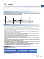
1.3
Restart . . . . . . . . . . . . . . . . . . . . . . . . . . . . . . . . . . . . . . . . . . . . . . . . . . . . . . . . . . . . . . . . . . . . . . . . . . . . . . . . 29
Multiple axes simultaneous start . . . . . . . . . . . . . . . . . . . . . . . . . . . . . . . . . . . . . . . . . . . . . . . . . . . . . . . . . . . . . 23
CHAPTER 2
2.1
HOME POSITION RETURN CONTROL
CONTENTS
TERMS . . . . . . . . . . . . . . . . . . . . . . . . . . . . . . . . . . . . . . . . . . . . . . . . . . . . . . . . . . . . . . . . . . . . . . . . . . . . . . . . .18
31
Outline of Home Position Return Control . . . . . . . . . . . . . . . . . . . . . . . . . . . . . . . . . . . . . . . . . . . . . . . . . . . . 31
Two types of home position return control. . . . . . . . . . . . . . . . . . . . . . . . . . . . . . . . . . . . . . . . . . . . . . . . . . . . . . 31
2.2
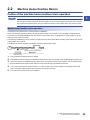
Machine Home Position Return . . . . . . . . . . . . . . . . . . . . . . . . . . . . . . . . . . . . . . . . . . . . . . . . . . . . . . . . . . . . 33
Outline of the machine home position return operation. . . . . . . . . . . . . . . . . . . . . . . . . . . . . . . . . . . . . . . . . . . . 33
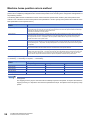
Machine home position return method . . . . . . . . . . . . . . . . . . . . . . . . . . . . . . . . . . . . . . . . . . . . . . . . . . . . . . . . 34
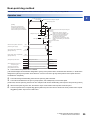
Near-point dog method . . . . . . . . . . . . . . . . . . . . . . . . . . . . . . . . . . . . . . . . . . . . . . . . . . . . . . . . . . . . . . . . . . . . 35
Count method1 . . . . . . . . . . . . . . . . . . . . . . . . . . . . . . . . . . . . . . . . . . . . . . . . . . . . . . . . . . . . . . . . . . . . . . . . . . 37
Count method2 . . . . . . . . . . . . . . . . . . . . . . . . . . . . . . . . . . . . . . . . . . . . . . . . . . . . . . . . . . . . . . . . . . . . . . . . . . 39
Data set method . . . . . . . . . . . . . . . . . . . . . . . . . . . . . . . . . . . . . . . . . . . . . . . . . . . . . . . . . . . . . . . . . . . . . . . . . 41
Scale origin signal detection method. . . . . . . . . . . . . . . . . . . . . . . . . . . . . . . . . . . . . . . . . . . . . . . . . . . . . . . . . . 42
2.3
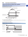
Fast Home Position Return . . . . . . . . . . . . . . . . . . . . . . . . . . . . . . . . . . . . . . . . . . . . . . . . . . . . . . . . . . . . . . . 45
Outline of the fast home position return operation. . . . . . . . . . . . . . . . . . . . . . . . . . . . . . . . . . . . . . . . . . . . . . . . 45
2.4
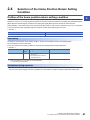
Selection of the Home Position Return Setting Condition . . . . . . . . . . . . . . . . . . . . . . . . . . . . . . . . . . . . . . 47
Outline of the home position return setting condition . . . . . . . . . . . . . . . . . . . . . . . . . . . . . . . . . . . . . . . . . . . . . 47
CHAPTER 3
3.1
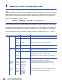
MAJOR POSITIONING CONTROL
48
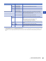
Outline of Major Positioning Controls. . . . . . . . . . . . . . . . . . . . . . . . . . . . . . . . . . . . . . . . . . . . . . . . . . . . . . . 48
Data required for major positioning control . . . . . . . . . . . . . . . . . . . . . . . . . . . . . . . . . . . . . . . . . . . . . . . . . . . . . 50
Operation patterns of major positioning controls . . . . . . . . . . . . . . . . . . . . . . . . . . . . . . . . . . . . . . . . . . . . . . . . . 51
Designating the positioning address . . . . . . . . . . . . . . . . . . . . . . . . . . . . . . . . . . . . . . . . . . . . . . . . . . . . . . . . . . 58
Confirming the current value . . . . . . . . . . . . . . . . . . . . . . . . . . . . . . . . . . . . . . . . . . . . . . . . . . . . . . . . . . . . . . . . 59
Control unit "degree" handling. . . . . . . . . . . . . . . . . . . . . . . . . . . . . . . . . . . . . . . . . . . . . . . . . . . . . . . . . . . . . . . 61
Interpolation control . . . . . . . . . . . . . . . . . . . . . . . . . . . . . . . . . . . . . . . . . . . . . . . . . . . . . . . . . . . . . . . . . . . . . . . 64
3.2
Setting the Positioning Data. . . . . . . . . . . . . . . . . . . . . . . . . . . . . . . . . . . . . . . . . . . . . . . . . . . . . . . . . . . . . . . 68
Relation between each control and positioning data . . . . . . . . . . . . . . . . . . . . . . . . . . . . . . . . . . . . . . . . . . . . . . 68
1-axis linear control . . . . . . . . . . . . . . . . . . . . . . . . . . . . . . . . . . . . . . . . . . . . . . . . . . . . . . . . . . . . . . . . . . . . . . . 71
2-axis linear interpolation control. . . . . . . . . . . . . . . . . . . . . . . . . . . . . . . . . . . . . . . . . . . . . . . . . . . . . . . . . . . . . 73
3-axis linear interpolation control. . . . . . . . . . . . . . . . . . . . . . . . . . . . . . . . . . . . . . . . . . . . . . . . . . . . . . . . . . . . . 77
4-axis linear interpolation control. . . . . . . . . . . . . . . . . . . . . . . . . . . . . . . . . . . . . . . . . . . . . . . . . . . . . . . . . . . . . 81
Fixed-feed control . . . . . . . . . . . . . . . . . . . . . . . . . . . . . . . . . . . . . . . . . . . . . . . . . . . . . . . . . . . . . . . . . . . . . . . . 83
2-axis circular interpolation control with sub point designation . . . . . . . . . . . . . . . . . . . . . . . . . . . . . . . . . . . . . . 86
2-axis circular interpolation control with center point designation . . . . . . . . . . . . . . . . . . . . . . . . . . . . . . . . . . . . 90
3-axis helical interpolation control with sub point designation . . . . . . . . . . . . . . . . . . . . . . . . . . . . . . . . . . . . . . . 95
3-axis helical interpolation control with center point designation. . . . . . . . . . . . . . . . . . . . . . . . . . . . . . . . . . . . 101
11
Speed control . . . . . . . . . . . . . . . . . . . . . . . . . . . . . . . . . . . . . . . . . . . . . . . . . . . . . . . . . . . . . . . . . . . . . . . . . . 108
Speed-position switching control (INC mode) . . . . . . . . . . . . . . . . . . . . . . . . . . . . . . . . . . . . . . . . . . . . . . . . . . 112
Speed-position switching control (ABS mode). . . . . . . . . . . . . . . . . . . . . . . . . . . . . . . . . . . . . . . . . . . . . . . . . . 119
Position-speed switching control . . . . . . . . . . . . . . . . . . . . . . . . . . . . . . . . . . . . . . . . . . . . . . . . . . . . . . . . . . . . 126
Current value changing . . . . . . . . . . . . . . . . . . . . . . . . . . . . . . . . . . . . . . . . . . . . . . . . . . . . . . . . . . . . . . . . . . . 133
NOP instruction . . . . . . . . . . . . . . . . . . . . . . . . . . . . . . . . . . . . . . . . . . . . . . . . . . . . . . . . . . . . . . . . . . . . . . . . . 138
JUMP instruction . . . . . . . . . . . . . . . . . . . . . . . . . . . . . . . . . . . . . . . . . . . . . . . . . . . . . . . . . . . . . . . . . . . . . . . . 139
LOOP. . . . . . . . . . . . . . . . . . . . . . . . . . . . . . . . . . . . . . . . . . . . . . . . . . . . . . . . . . . . . . . . . . . . . . . . . . . . . . . . . 141
LEND . . . . . . . . . . . . . . . . . . . . . . . . . . . . . . . . . . . . . . . . . . . . . . . . . . . . . . . . . . . . . . . . . . . . . . . . . . . . . . . . . 142
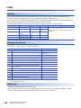
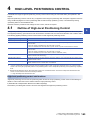
CHAPTER 4
4.1
HIGH-LEVEL POSITIONING CONTROL
143
Outline of High-level Positioning Control . . . . . . . . . . . . . . . . . . . . . . . . . . . . . . . . . . . . . . . . . . . . . . . . . . . 143
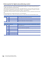
Data required for high-level positioning control . . . . . . . . . . . . . . . . . . . . . . . . . . . . . . . . . . . . . . . . . . . . . . . . . 144
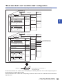
"Block start data" and "condition data" configuration. . . . . . . . . . . . . . . . . . . . . . . . . . . . . . . . . . . . . . . . . . . . . 145
4.2
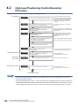
High-level Positioning Control Execution Procedure . . . . . . . . . . . . . . . . . . . . . . . . . . . . . . . . . . . . . . . . . 146
4.3
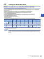
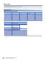
Setting the Block Start Data . . . . . . . . . . . . . . . . . . . . . . . . . . . . . . . . . . . . . . . . . . . . . . . . . . . . . . . . . . . . . . 147
Relation between various controls and block start data . . . . . . . . . . . . . . . . . . . . . . . . . . . . . . . . . . . . . . . . . . 147
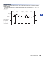
Block start . . . . . . . . . . . . . . . . . . . . . . . . . . . . . . . . . . . . . . . . . . . . . . . . . . . . . . . . . . . . . . . . . . . . . . . . . . . . . 148
Condition start . . . . . . . . . . . . . . . . . . . . . . . . . . . . . . . . . . . . . . . . . . . . . . . . . . . . . . . . . . . . . . . . . . . . . . . . . . 150
Wait start . . . . . . . . . . . . . . . . . . . . . . . . . . . . . . . . . . . . . . . . . . . . . . . . . . . . . . . . . . . . . . . . . . . . . . . . . . . . . . 151
Simultaneous start. . . . . . . . . . . . . . . . . . . . . . . . . . . . . . . . . . . . . . . . . . . . . . . . . . . . . . . . . . . . . . . . . . . . . . . 152
Repeated start (FOR loop) . . . . . . . . . . . . . . . . . . . . . . . . . . . . . . . . . . . . . . . . . . . . . . . . . . . . . . . . . . . . . . . . 153
Repeated start (FOR condition). . . . . . . . . . . . . . . . . . . . . . . . . . . . . . . . . . . . . . . . . . . . . . . . . . . . . . . . . . . . . 154
Restrictions when using the NEXT start . . . . . . . . . . . . . . . . . . . . . . . . . . . . . . . . . . . . . . . . . . . . . . . . . . . . . . 155
4.4
Setting the Condition Data . . . . . . . . . . . . . . . . . . . . . . . . . . . . . . . . . . . . . . . . . . . . . . . . . . . . . . . . . . . . . . . 156
Relation between various controls and the condition data . . . . . . . . . . . . . . . . . . . . . . . . . . . . . . . . . . . . . . . . 156
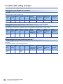
Condition data setting examples . . . . . . . . . . . . . . . . . . . . . . . . . . . . . . . . . . . . . . . . . . . . . . . . . . . . . . . . . . . . 158
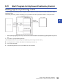
4.5
Start Program for High-level Positioning Control . . . . . . . . . . . . . . . . . . . . . . . . . . . . . . . . . . . . . . . . . . . . 159
Starting high-level positioning control . . . . . . . . . . . . . . . . . . . . . . . . . . . . . . . . . . . . . . . . . . . . . . . . . . . . . . . . 159
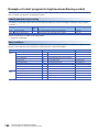
Example of a start program for high-level positioning control . . . . . . . . . . . . . . . . . . . . . . . . . . . . . . . . . . . . . . 160
CHAPTER 5
5.1
MANUAL CONTROL
163
Outline of Manual Control. . . . . . . . . . . . . . . . . . . . . . . . . . . . . . . . . . . . . . . . . . . . . . . . . . . . . . . . . . . . . . . . 163
Three manual control methods . . . . . . . . . . . . . . . . . . . . . . . . . . . . . . . . . . . . . . . . . . . . . . . . . . . . . . . . . . . . . 163
5.2
JOG Operation . . . . . . . . . . . . . . . . . . . . . . . . . . . . . . . . . . . . . . . . . . . . . . . . . . . . . . . . . . . . . . . . . . . . . . . . . 165
Outline of JOG operation. . . . . . . . . . . . . . . . . . . . . . . . . . . . . . . . . . . . . . . . . . . . . . . . . . . . . . . . . . . . . . . . . . 165
JOG operation execution procedure . . . . . . . . . . . . . . . . . . . . . . . . . . . . . . . . . . . . . . . . . . . . . . . . . . . . . . . . . 168
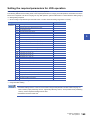
Setting the required parameters for JOG operation . . . . . . . . . . . . . . . . . . . . . . . . . . . . . . . . . . . . . . . . . . . . . 169
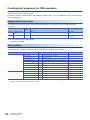
Creating start programs for JOG operation . . . . . . . . . . . . . . . . . . . . . . . . . . . . . . . . . . . . . . . . . . . . . . . . . . . . 170
JOG operation example. . . . . . . . . . . . . . . . . . . . . . . . . . . . . . . . . . . . . . . . . . . . . . . . . . . . . . . . . . . . . . . . . . . 172
5.3
Inching Operation . . . . . . . . . . . . . . . . . . . . . . . . . . . . . . . . . . . . . . . . . . . . . . . . . . . . . . . . . . . . . . . . . . . . . . 174
Outline of inching operation. . . . . . . . . . . . . . . . . . . . . . . . . . . . . . . . . . . . . . . . . . . . . . . . . . . . . . . . . . . . . . . . 174
Inching operation execution procedure . . . . . . . . . . . . . . . . . . . . . . . . . . . . . . . . . . . . . . . . . . . . . . . . . . . . . . . 177
Setting the required parameters for inching operation . . . . . . . . . . . . . . . . . . . . . . . . . . . . . . . . . . . . . . . . . . . 178
Creating a program to enable/disable the inching operation . . . . . . . . . . . . . . . . . . . . . . . . . . . . . . . . . . . . . . . 179
Inching operation example . . . . . . . . . . . . . . . . . . . . . . . . . . . . . . . . . . . . . . . . . . . . . . . . . . . . . . . . . . . . . . . . 181
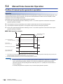
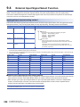
5.4
Manual Pulse Generator Operation . . . . . . . . . . . . . . . . . . . . . . . . . . . . . . . . . . . . . . . . . . . . . . . . . . . . . . . . 182
Outline of manual pulse generator operation . . . . . . . . . . . . . . . . . . . . . . . . . . . . . . . . . . . . . . . . . . . . . . . . . . 182
Manual pulse generator operation execution procedure . . . . . . . . . . . . . . . . . . . . . . . . . . . . . . . . . . . . . . . . . . 187
Setting the required parameters for manual pulse generator operation . . . . . . . . . . . . . . . . . . . . . . . . . . . . . . 188
12
Creating a program to enable/disable the manual pulse generator operation. . . . . . . . . . . . . . . . . . . . . . . . . . 189
CHAPTER 6
INTER-MODULE SYNCHRONIZATION FUNCTION
191
CHAPTER 7
EXPANSION CONTROL
193
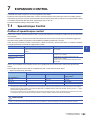
7.1
Speed-torque Control . . . . . . . . . . . . . . . . . . . . . . . . . . . . . . . . . . . . . . . . . . . . . . . . . . . . . . . . . . . . . . . . . . . 193
Outline of speed-torque control . . . . . . . . . . . . . . . . . . . . . . . . . . . . . . . . . . . . . . . . . . . . . . . . . . . . . . . . . . . . . 193
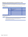
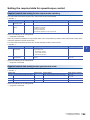
Setting the required parameters for speed-torque control. . . . . . . . . . . . . . . . . . . . . . . . . . . . . . . . . . . . . . . . . 194
Operation of speed-torque control. . . . . . . . . . . . . . . . . . . . . . . . . . . . . . . . . . . . . . . . . . . . . . . . . . . . . . . . . . . 197
7.2
Synchronous Control . . . . . . . . . . . . . . . . . . . . . . . . . . . . . . . . . . . . . . . . . . . . . . . . . . . . . . . . . . . . . . . . . . . 214
CHAPTER 8
CONTROL SUB FUNCTIONS
215
8.1
Outline of Sub Functions . . . . . . . . . . . . . . . . . . . . . . . . . . . . . . . . . . . . . . . . . . . . . . . . . . . . . . . . . . . . . . . . 215
8.2
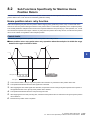
Sub Functions Specifically for Machine Home Position Return . . . . . . . . . . . . . . . . . . . . . . . . . . . . . . . . . 217
Outline of sub functions . . . . . . . . . . . . . . . . . . . . . . . . . . . . . . . . . . . . . . . . . . . . . . . . . . . . . . . . . . . . . . . . . . . 215
CONTENTS
Setting the required data for speed-torque control . . . . . . . . . . . . . . . . . . . . . . . . . . . . . . . . . . . . . . . . . . . . . . 195
Home position return retry function . . . . . . . . . . . . . . . . . . . . . . . . . . . . . . . . . . . . . . . . . . . . . . . . . . . . . . . . . . 217
Home position shift function . . . . . . . . . . . . . . . . . . . . . . . . . . . . . . . . . . . . . . . . . . . . . . . . . . . . . . . . . . . . . . . 221
8.3
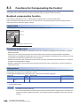
Functions for Compensating the Control . . . . . . . . . . . . . . . . . . . . . . . . . . . . . . . . . . . . . . . . . . . . . . . . . . . 224
Backlash compensation function . . . . . . . . . . . . . . . . . . . . . . . . . . . . . . . . . . . . . . . . . . . . . . . . . . . . . . . . . . . . 224
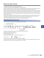
Electronic gear function . . . . . . . . . . . . . . . . . . . . . . . . . . . . . . . . . . . . . . . . . . . . . . . . . . . . . . . . . . . . . . . . . . . 225
Near pass function. . . . . . . . . . . . . . . . . . . . . . . . . . . . . . . . . . . . . . . . . . . . . . . . . . . . . . . . . . . . . . . . . . . . . . . 231
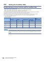
8.4
Functions to Limit the Control . . . . . . . . . . . . . . . . . . . . . . . . . . . . . . . . . . . . . . . . . . . . . . . . . . . . . . . . . . . . 233
Speed limit function . . . . . . . . . . . . . . . . . . . . . . . . . . . . . . . . . . . . . . . . . . . . . . . . . . . . . . . . . . . . . . . . . . . . . . 233
Torque limit function. . . . . . . . . . . . . . . . . . . . . . . . . . . . . . . . . . . . . . . . . . . . . . . . . . . . . . . . . . . . . . . . . . . . . . 235
Software stroke limit function. . . . . . . . . . . . . . . . . . . . . . . . . . . . . . . . . . . . . . . . . . . . . . . . . . . . . . . . . . . . . . . 238
Hardware stroke limit function . . . . . . . . . . . . . . . . . . . . . . . . . . . . . . . . . . . . . . . . . . . . . . . . . . . . . . . . . . . . . . 243
Forced stop function . . . . . . . . . . . . . . . . . . . . . . . . . . . . . . . . . . . . . . . . . . . . . . . . . . . . . . . . . . . . . . . . . . . . . 246
8.5
Functions to Change the Control Details . . . . . . . . . . . . . . . . . . . . . . . . . . . . . . . . . . . . . . . . . . . . . . . . . . . 248
Speed change function . . . . . . . . . . . . . . . . . . . . . . . . . . . . . . . . . . . . . . . . . . . . . . . . . . . . . . . . . . . . . . . . . . . 248
Override function . . . . . . . . . . . . . . . . . . . . . . . . . . . . . . . . . . . . . . . . . . . . . . . . . . . . . . . . . . . . . . . . . . . . . . . . 254
Acceleration/deceleration time change function . . . . . . . . . . . . . . . . . . . . . . . . . . . . . . . . . . . . . . . . . . . . . . . . 256
Torque change function . . . . . . . . . . . . . . . . . . . . . . . . . . . . . . . . . . . . . . . . . . . . . . . . . . . . . . . . . . . . . . . . . . . 259
Target position change function. . . . . . . . . . . . . . . . . . . . . . . . . . . . . . . . . . . . . . . . . . . . . . . . . . . . . . . . . . . . . 263
8.6
Functions Related to Start . . . . . . . . . . . . . . . . . . . . . . . . . . . . . . . . . . . . . . . . . . . . . . . . . . . . . . . . . . . . . . . 266
Pre-reading start function . . . . . . . . . . . . . . . . . . . . . . . . . . . . . . . . . . . . . . . . . . . . . . . . . . . . . . . . . . . . . . . . . 266
8.7
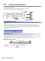
Absolute Position System . . . . . . . . . . . . . . . . . . . . . . . . . . . . . . . . . . . . . . . . . . . . . . . . . . . . . . . . . . . . . . . 268
8.8
Functions Related to Stop . . . . . . . . . . . . . . . . . . . . . . . . . . . . . . . . . . . . . . . . . . . . . . . . . . . . . . . . . . . . . . . 269
Stop command processing for deceleration stop function . . . . . . . . . . . . . . . . . . . . . . . . . . . . . . . . . . . . . . . . . 269
Continuous operation interrupt function. . . . . . . . . . . . . . . . . . . . . . . . . . . . . . . . . . . . . . . . . . . . . . . . . . . . . . . 271
Step function . . . . . . . . . . . . . . . . . . . . . . . . . . . . . . . . . . . . . . . . . . . . . . . . . . . . . . . . . . . . . . . . . . . . . . . . . . . 273
8.9
Other Functions. . . . . . . . . . . . . . . . . . . . . . . . . . . . . . . . . . . . . . . . . . . . . . . . . . . . . . . . . . . . . . . . . . . . . . . . 278
Skip function . . . . . . . . . . . . . . . . . . . . . . . . . . . . . . . . . . . . . . . . . . . . . . . . . . . . . . . . . . . . . . . . . . . . . . . . . . . 278
M code output function . . . . . . . . . . . . . . . . . . . . . . . . . . . . . . . . . . . . . . . . . . . . . . . . . . . . . . . . . . . . . . . . . . . 281
Teaching function. . . . . . . . . . . . . . . . . . . . . . . . . . . . . . . . . . . . . . . . . . . . . . . . . . . . . . . . . . . . . . . . . . . . . . . . 285
Command in-position function . . . . . . . . . . . . . . . . . . . . . . . . . . . . . . . . . . . . . . . . . . . . . . . . . . . . . . . . . . . . . . 290
Acceleration/deceleration processing function . . . . . . . . . . . . . . . . . . . . . . . . . . . . . . . . . . . . . . . . . . . . . . . . . 292
Deceleration start flag function . . . . . . . . . . . . . . . . . . . . . . . . . . . . . . . . . . . . . . . . . . . . . . . . . . . . . . . . . . . . . 294
Speed control 10 times multiplier setting for degree axis function. . . . . . . . . . . . . . . . . . . . . . . . . . . . . . . . . . . 297
Operation setting for incompletion of home position return function . . . . . . . . . . . . . . . . . . . . . . . . . . . . . . . . . 299
13
8.10
Servo ON/OFF . . . . . . . . . . . . . . . . . . . . . . . . . . . . . . . . . . . . . . . . . . . . . . . . . . . . . . . . . . . . . . . . . . . . . . . . . 301
Servo ON/OFF. . . . . . . . . . . . . . . . . . . . . . . . . . . . . . . . . . . . . . . . . . . . . . . . . . . . . . . . . . . . . . . . . . . . . . . . . . 301
Follow up function . . . . . . . . . . . . . . . . . . . . . . . . . . . . . . . . . . . . . . . . . . . . . . . . . . . . . . . . . . . . . . . . . . . . . . . 302
CHAPTER 9
COMMON FUNCTIONS
303
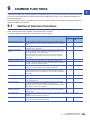
9.1
Outline of Common Functions . . . . . . . . . . . . . . . . . . . . . . . . . . . . . . . . . . . . . . . . . . . . . . . . . . . . . . . . . . . . 303
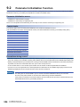
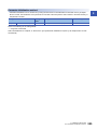
9.2
Parameter Initialization Function . . . . . . . . . . . . . . . . . . . . . . . . . . . . . . . . . . . . . . . . . . . . . . . . . . . . . . . . . . 304
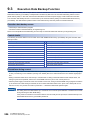
9.3
Execution Data Backup Function . . . . . . . . . . . . . . . . . . . . . . . . . . . . . . . . . . . . . . . . . . . . . . . . . . . . . . . . . 306
9.4
External Input Signal Select Function . . . . . . . . . . . . . . . . . . . . . . . . . . . . . . . . . . . . . . . . . . . . . . . . . . . . . . 308
9.5
History Monitor Function . . . . . . . . . . . . . . . . . . . . . . . . . . . . . . . . . . . . . . . . . . . . . . . . . . . . . . . . . . . . . . . . 316
9.6
Amplifier-less Operation Function. . . . . . . . . . . . . . . . . . . . . . . . . . . . . . . . . . . . . . . . . . . . . . . . . . . . . . . . . 319
9.7
Virtual Servo Amplifier Function . . . . . . . . . . . . . . . . . . . . . . . . . . . . . . . . . . . . . . . . . . . . . . . . . . . . . . . . . . 323
9.8
Driver Communication Function . . . . . . . . . . . . . . . . . . . . . . . . . . . . . . . . . . . . . . . . . . . . . . . . . . . . . . . . . . 325
9.9
Mark Detection Function. . . . . . . . . . . . . . . . . . . . . . . . . . . . . . . . . . . . . . . . . . . . . . . . . . . . . . . . . . . . . . . . . 331
9.10
Optional Data Monitor Function . . . . . . . . . . . . . . . . . . . . . . . . . . . . . . . . . . . . . . . . . . . . . . . . . . . . . . . . . . . 340
9.11
Event History Function . . . . . . . . . . . . . . . . . . . . . . . . . . . . . . . . . . . . . . . . . . . . . . . . . . . . . . . . . . . . . . . . . . 342
9.12
Connect/Disconnect Function of SSCNET Communication . . . . . . . . . . . . . . . . . . . . . . . . . . . . . . . . . . . . 345
9.13
Online module change . . . . . . . . . . . . . . . . . . . . . . . . . . . . . . . . . . . . . . . . . . . . . . . . . . . . . . . . . . . . . . . . . . 349
9.14
Hot line forced stop function . . . . . . . . . . . . . . . . . . . . . . . . . . . . . . . . . . . . . . . . . . . . . . . . . . . . . . . . . . . . . 350
CHAPTER 10 PARAMETER SETTING
352
10.1
Parameter Setting Procedure . . . . . . . . . . . . . . . . . . . . . . . . . . . . . . . . . . . . . . . . . . . . . . . . . . . . . . . . . . . . . 352
10.2
Module Parameters . . . . . . . . . . . . . . . . . . . . . . . . . . . . . . . . . . . . . . . . . . . . . . . . . . . . . . . . . . . . . . . . . . . . . 352
10.3
Simple Motion Module Setting . . . . . . . . . . . . . . . . . . . . . . . . . . . . . . . . . . . . . . . . . . . . . . . . . . . . . . . . . . . . 356
Refresh settings. . . . . . . . . . . . . . . . . . . . . . . . . . . . . . . . . . . . . . . . . . . . . . . . . . . . . . . . . . . . . . . . . . . . . . . . . 352
CHAPTER 11 SPECIFICATIONS OF I/O SIGNALS WITH CPU MODULES
357
11.1
List of Input/Output Signals with CPU Modules . . . . . . . . . . . . . . . . . . . . . . . . . . . . . . . . . . . . . . . . . . . . . . 357
11.2
Details of Input Signals. . . . . . . . . . . . . . . . . . . . . . . . . . . . . . . . . . . . . . . . . . . . . . . . . . . . . . . . . . . . . . . . . . 359
11.3
Details of Output Signals . . . . . . . . . . . . . . . . . . . . . . . . . . . . . . . . . . . . . . . . . . . . . . . . . . . . . . . . . . . . . . . . 360
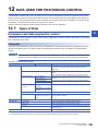
CHAPTER 12 DATA USED FOR POSITIONING CONTROL
12.1
361
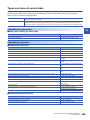
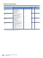
Types of Data . . . . . . . . . . . . . . . . . . . . . . . . . . . . . . . . . . . . . . . . . . . . . . . . . . . . . . . . . . . . . . . . . . . . . . . . . . 361
Parameters and data required for control . . . . . . . . . . . . . . . . . . . . . . . . . . . . . . . . . . . . . . . . . . . . . . . . . . . . . 361
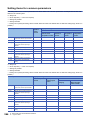
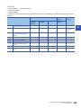
Setting items for servo network composition parameters . . . . . . . . . . . . . . . . . . . . . . . . . . . . . . . . . . . . . . . . . 363
Setting items for common parameters. . . . . . . . . . . . . . . . . . . . . . . . . . . . . . . . . . . . . . . . . . . . . . . . . . . . . . . . 364
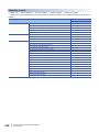
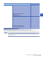
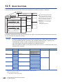
Setting items for positioning parameters . . . . . . . . . . . . . . . . . . . . . . . . . . . . . . . . . . . . . . . . . . . . . . . . . . . . . . 366
Setting items for home position return parameters . . . . . . . . . . . . . . . . . . . . . . . . . . . . . . . . . . . . . . . . . . . . . . 376
Setting items for expansion parameters . . . . . . . . . . . . . . . . . . . . . . . . . . . . . . . . . . . . . . . . . . . . . . . . . . . . . . 377
Setting items for servo parameters . . . . . . . . . . . . . . . . . . . . . . . . . . . . . . . . . . . . . . . . . . . . . . . . . . . . . . . . . . 377
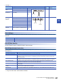
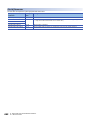
Setting items for positioning data . . . . . . . . . . . . . . . . . . . . . . . . . . . . . . . . . . . . . . . . . . . . . . . . . . . . . . . . . . . 378
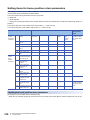
Setting items for block start data . . . . . . . . . . . . . . . . . . . . . . . . . . . . . . . . . . . . . . . . . . . . . . . . . . . . . . . . . . . . 381
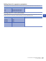
Setting items for condition data . . . . . . . . . . . . . . . . . . . . . . . . . . . . . . . . . . . . . . . . . . . . . . . . . . . . . . . . . . . . . 381
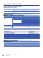
Types and roles of monitor data . . . . . . . . . . . . . . . . . . . . . . . . . . . . . . . . . . . . . . . . . . . . . . . . . . . . . . . . . . . . 382
Types and roles of control data . . . . . . . . . . . . . . . . . . . . . . . . . . . . . . . . . . . . . . . . . . . . . . . . . . . . . . . . . . . . . 385
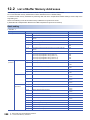
12.2
List of Buffer Memory Addresses . . . . . . . . . . . . . . . . . . . . . . . . . . . . . . . . . . . . . . . . . . . . . . . . . . . . . . . . . 388
12.3
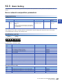
Basic Setting . . . . . . . . . . . . . . . . . . . . . . . . . . . . . . . . . . . . . . . . . . . . . . . . . . . . . . . . . . . . . . . . . . . . . . . . . . 407
Servo network composition parameters . . . . . . . . . . . . . . . . . . . . . . . . . . . . . . . . . . . . . . . . . . . . . . . . . . . . . . 407
Common parameters. . . . . . . . . . . . . . . . . . . . . . . . . . . . . . . . . . . . . . . . . . . . . . . . . . . . . . . . . . . . . . . . . . . . . 408
Basic parameters1. . . . . . . . . . . . . . . . . . . . . . . . . . . . . . . . . . . . . . . . . . . . . . . . . . . . . . . . . . . . . . . . . . . . . . . 414
14
Basic parameters2. . . . . . . . . . . . . . . . . . . . . . . . . . . . . . . . . . . . . . . . . . . . . . . . . . . . . . . . . . . . . . . . . . . . . . . 417
Detailed parameters1 . . . . . . . . . . . . . . . . . . . . . . . . . . . . . . . . . . . . . . . . . . . . . . . . . . . . . . . . . . . . . . . . . . . . 418
Detailed parameters2 . . . . . . . . . . . . . . . . . . . . . . . . . . . . . . . . . . . . . . . . . . . . . . . . . . . . . . . . . . . . . . . . . . . . 425
Home position return basic parameters. . . . . . . . . . . . . . . . . . . . . . . . . . . . . . . . . . . . . . . . . . . . . . . . . . . . . . . 435
Home position return detailed parameters . . . . . . . . . . . . . . . . . . . . . . . . . . . . . . . . . . . . . . . . . . . . . . . . . . . . 438
Expansion parameters. . . . . . . . . . . . . . . . . . . . . . . . . . . . . . . . . . . . . . . . . . . . . . . . . . . . . . . . . . . . . . . . . . . . 442
Servo parameters . . . . . . . . . . . . . . . . . . . . . . . . . . . . . . . . . . . . . . . . . . . . . . . . . . . . . . . . . . . . . . . . . . . . . . . 444
Positioning Data . . . . . . . . . . . . . . . . . . . . . . . . . . . . . . . . . . . . . . . . . . . . . . . . . . . . . . . . . . . . . . . . . . . . . . . 445
12.5
Block Start Data . . . . . . . . . . . . . . . . . . . . . . . . . . . . . . . . . . . . . . . . . . . . . . . . . . . . . . . . . . . . . . . . . . . . . . . . 460
12.6
Condition Data . . . . . . . . . . . . . . . . . . . . . . . . . . . . . . . . . . . . . . . . . . . . . . . . . . . . . . . . . . . . . . . . . . . . . . . . . 463
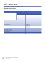
12.7
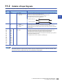
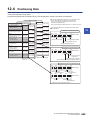
Monitor Data. . . . . . . . . . . . . . . . . . . . . . . . . . . . . . . . . . . . . . . . . . . . . . . . . . . . . . . . . . . . . . . . . . . . . . . . . . . 468
System monitor data . . . . . . . . . . . . . . . . . . . . . . . . . . . . . . . . . . . . . . . . . . . . . . . . . . . . . . . . . . . . . . . . . . . . . 468
Axis monitor data. . . . . . . . . . . . . . . . . . . . . . . . . . . . . . . . . . . . . . . . . . . . . . . . . . . . . . . . . . . . . . . . . . . . . . . . 477
Servo network composition status. . . . . . . . . . . . . . . . . . . . . . . . . . . . . . . . . . . . . . . . . . . . . . . . . . . . . . . . . . . 503
12.8
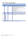
Control Data . . . . . . . . . . . . . . . . . . . . . . . . . . . . . . . . . . . . . . . . . . . . . . . . . . . . . . . . . . . . . . . . . . . . . . . . . . . 504
System control data. . . . . . . . . . . . . . . . . . . . . . . . . . . . . . . . . . . . . . . . . . . . . . . . . . . . . . . . . . . . . . . . . . . . . . 504
CONTENTS
12.4
Axis control data . . . . . . . . . . . . . . . . . . . . . . . . . . . . . . . . . . . . . . . . . . . . . . . . . . . . . . . . . . . . . . . . . . . . . . . . 509
12.9
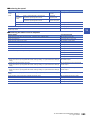
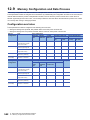
Memory Configuration and Data Process . . . . . . . . . . . . . . . . . . . . . . . . . . . . . . . . . . . . . . . . . . . . . . . . . . . 542
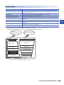
Configuration and roles . . . . . . . . . . . . . . . . . . . . . . . . . . . . . . . . . . . . . . . . . . . . . . . . . . . . . . . . . . . . . . . . . . . 542
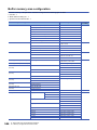
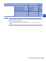
Buffer memory area configuration . . . . . . . . . . . . . . . . . . . . . . . . . . . . . . . . . . . . . . . . . . . . . . . . . . . . . . . . . . . 544
Data transmission process . . . . . . . . . . . . . . . . . . . . . . . . . . . . . . . . . . . . . . . . . . . . . . . . . . . . . . . . . . . . . . . . 546
CHAPTER 13 PROGRAMMING
556
13.1
Precautions for Creating Program. . . . . . . . . . . . . . . . . . . . . . . . . . . . . . . . . . . . . . . . . . . . . . . . . . . . . . . . . 556
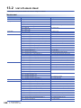
13.2
List of Labels Used . . . . . . . . . . . . . . . . . . . . . . . . . . . . . . . . . . . . . . . . . . . . . . . . . . . . . . . . . . . . . . . . . . . . . 558
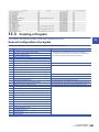
13.3
Creating a Program . . . . . . . . . . . . . . . . . . . . . . . . . . . . . . . . . . . . . . . . . . . . . . . . . . . . . . . . . . . . . . . . . . . . . 561
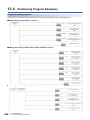
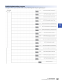
13.4
Positioning Program Examples . . . . . . . . . . . . . . . . . . . . . . . . . . . . . . . . . . . . . . . . . . . . . . . . . . . . . . . . . . . 562
General configuration of program . . . . . . . . . . . . . . . . . . . . . . . . . . . . . . . . . . . . . . . . . . . . . . . . . . . . . . . . . . . 561
CHAPTER 14 TROUBLESHOOTING
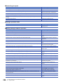
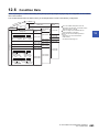
14.1
574
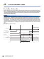
Troubleshooting Procedure . . . . . . . . . . . . . . . . . . . . . . . . . . . . . . . . . . . . . . . . . . . . . . . . . . . . . . . . . . . . . . 574
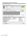
Troubleshooting using the LEDs . . . . . . . . . . . . . . . . . . . . . . . . . . . . . . . . . . . . . . . . . . . . . . . . . . . . . . . . . . . . 574
Troubleshooting using the module status . . . . . . . . . . . . . . . . . . . . . . . . . . . . . . . . . . . . . . . . . . . . . . . . . . . . . 576
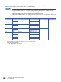
14.2
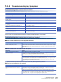
Troubleshooting by Symptom . . . . . . . . . . . . . . . . . . . . . . . . . . . . . . . . . . . . . . . . . . . . . . . . . . . . . . . . . . . . 577
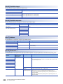
14.3
Error and Warning Details . . . . . . . . . . . . . . . . . . . . . . . . . . . . . . . . . . . . . . . . . . . . . . . . . . . . . . . . . . . . . . . 578
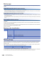
Error type. . . . . . . . . . . . . . . . . . . . . . . . . . . . . . . . . . . . . . . . . . . . . . . . . . . . . . . . . . . . . . . . . . . . . . . . . . . . . . 578
Error code classification . . . . . . . . . . . . . . . . . . . . . . . . . . . . . . . . . . . . . . . . . . . . . . . . . . . . . . . . . . . . . . . . . . 579
Error storage . . . . . . . . . . . . . . . . . . . . . . . . . . . . . . . . . . . . . . . . . . . . . . . . . . . . . . . . . . . . . . . . . . . . . . . . . . . 579
Warning type . . . . . . . . . . . . . . . . . . . . . . . . . . . . . . . . . . . . . . . . . . . . . . . . . . . . . . . . . . . . . . . . . . . . . . . . . . . 580
Warning code classification . . . . . . . . . . . . . . . . . . . . . . . . . . . . . . . . . . . . . . . . . . . . . . . . . . . . . . . . . . . . . . . . 580
Warning storage . . . . . . . . . . . . . . . . . . . . . . . . . . . . . . . . . . . . . . . . . . . . . . . . . . . . . . . . . . . . . . . . . . . . . . . . 580
Clearing errors and warnings . . . . . . . . . . . . . . . . . . . . . . . . . . . . . . . . . . . . . . . . . . . . . . . . . . . . . . . . . . . . . . 581
14.4
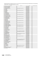
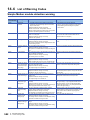
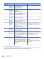
List of Warning Codes . . . . . . . . . . . . . . . . . . . . . . . . . . . . . . . . . . . . . . . . . . . . . . . . . . . . . . . . . . . . . . . . . . 582
Simple Motion module detection warning . . . . . . . . . . . . . . . . . . . . . . . . . . . . . . . . . . . . . . . . . . . . . . . . . . . . . 582
Servo amplifier detection warning . . . . . . . . . . . . . . . . . . . . . . . . . . . . . . . . . . . . . . . . . . . . . . . . . . . . . . . . . . . 590
14.5
List of Error Codes . . . . . . . . . . . . . . . . . . . . . . . . . . . . . . . . . . . . . . . . . . . . . . . . . . . . . . . . . . . . . . . . . . . . . 591
Simple Motion module detection error. . . . . . . . . . . . . . . . . . . . . . . . . . . . . . . . . . . . . . . . . . . . . . . . . . . . . . . . 591
Servo amplifier detection error . . . . . . . . . . . . . . . . . . . . . . . . . . . . . . . . . . . . . . . . . . . . . . . . . . . . . . . . . . . . . 618
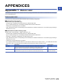
APPENDICES
619
15
Appendix 1 Module Label . . . . . . . . . . . . . . . . . . . . . . . . . . . . . . . . . . . . . . . . . . . . . . . . . . . . . . . . . . . . . . . . . . . . . 619
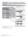
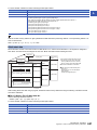
Appendix 2 How to Find Buffer Memory Addresses. . . . . . . . . . . . . . . . . . . . . . . . . . . . . . . . . . . . . . . . . . . . . . . . 620
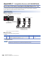
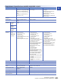
Appendix 3 Compatible Devices with SSCNETIII(/H) . . . . . . . . . . . . . . . . . . . . . . . . . . . . . . . . . . . . . . . . . . . . . . . 624
Servo driver VCII series manufactured by Nikki Denso Co., Ltd. . . . . . . . . . . . . . . . . . . . . . . . . . . . . . . . . . . . 624
Inverter FR-A700 series . . . . . . . . . . . . . . . . . . . . . . . . . . . . . . . . . . . . . . . . . . . . . . . . . . . . . . . . . . . . . . . . . . 628
Connection with MR-JE-B . . . . . . . . . . . . . . . . . . . . . . . . . . . . . . . . . . . . . . . . . . . . . . . . . . . . . . . . . . . . . . . . . 633
Appendix 4 Restrictions by the version. . . . . . . . . . . . . . . . . . . . . . . . . . . . . . . . . . . . . . . . . . . . . . . . . . . . . . . . . . 634
INDEX
635
REVISIONS . . . . . . . . . . . . . . . . . . . . . . . . . . . . . . . . . . . . . . . . . . . . . . . . . . . . . . . . . . . . . . . . . . . . . . . . . . . . .638
WARRANTY . . . . . . . . . . . . . . . . . . . . . . . . . . . . . . . . . . . . . . . . . . . . . . . . . . . . . . . . . . . . . . . . . . . . . . . . . . . .639
TRADEMARKS . . . . . . . . . . . . . . . . . . . . . . . . . . . . . . . . . . . . . . . . . . . . . . . . . . . . . . . . . . . . . . . . . . . . . . . . . .640
16
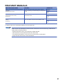
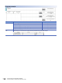
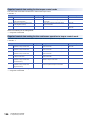
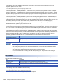
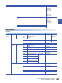
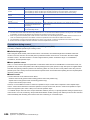
RELEVANT MANUALS
Manual name [manual number]
Description
Available form
MELSEC iQ-R Simple Motion Module User's Manual
(Application)
[IB-0300247] (This manual)
Functions, input/output signals, buffer memories, parameter
settings, programming, and troubleshooting of the Simple Motion
module
Print book
MELSEC iQ-R Simple Motion Module User's Manual
(Advanced Synchronous Control)
[IB-0300249]
Functions and programming for the synchronous control of the
Simple Motion module
Print book
MELSEC iQ-R Simple Motion Module User's Manual
(Startup)
[IB-0300245]
Specifications, procedures before operation, system configuration,
wiring, and operation examples of the Simple Motion module
Print book
e-Manual
EPUB
PDF
e-Manual
EPUB
PDF
e-Manual
EPUB
PDF
This manual does not include information on the module function blocks.
For details, refer to the Function Block Reference for the module used.
e-Manual refers to the Mitsubishi FA electronic book manuals that can be browsed using a dedicated tool.
e-Manual has the following features:
• Required information can be cross-searched in multiple manuals.
• Other manuals can be accessed from the links in the manual.
• The hardware specifications of each part can be found from the product figures.
• Pages that users often browse can be bookmarked.
17
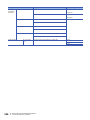
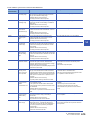
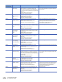
TERMS
Unless otherwise specified, this manual uses the following terms.
Term
Description
CPU module
Abbreviation for the MELSEC iQ-R series CPU module.
Simple Motion module
Abbreviation for the MELSEC iQ-R series Simple Motion module.
RD77MS
Another term for the MELSEC iQ-R series Simple Motion module.
Servo amplifier
Abbreviation for SSCNET/H and SSCNET compatible servo amplifier.
MR-J4(W)-B
MR-J4-_B/MR-J4W_-_B Servo amplifier series
MR-J3(W)-B
MR-J3-_B/MR-J3W-_B Servo amplifier series
MR-JE-B
MR-JE-_B Servo amplifier series
Engineering tool
Generic term for GX Works3 and MR Configurator2.
GX Works3
Product name of the software package for the MELSEC programmable controllers.
MR Configurator2
Product name of the setup software for the servo amplifier (Version 1.27D or later).
Intelligent function module
A MELSEC iQ-R series module that has functions other than input or output, such as A/D converter module and D/A
converter module
Manual pulse generator
Abbreviation for manual pulse generator (prepared by user).
SSCNET/H*1
High speed synchronous communication network between RD77MS and servo amplifier.
SSCNET*1
SSCNET(/H)
Generic term for SSCNET/H, SSCNET.
Servo network
2-axis module
Generic term for RD77MS2.
4-axis module
Generic term for RD77MS4.
8-axis module
Generic term for RD77MS8.
16-axis module
Generic term for RD77MS16.
*1
18
SSCNET: Servo System Controller NETwork
1
START AND STOP
1
This chapter describes start and stop methods of the positioning control for the Simple Motion module.
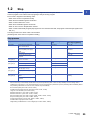
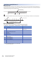
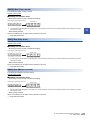
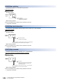
1.1
Start
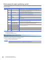
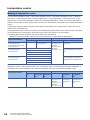
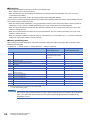
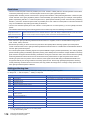
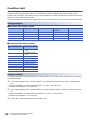
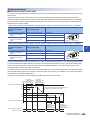
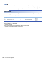
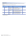
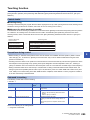
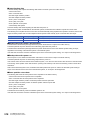
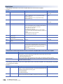
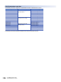
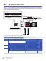
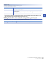
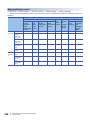
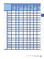
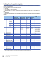
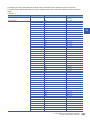
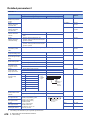
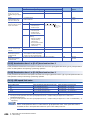
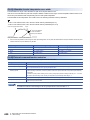
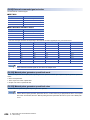
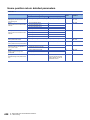
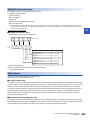
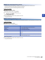
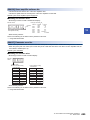
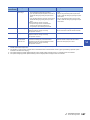
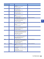
The Simple Motion module operates the start trigger in each control, and starts the positioning control. The following table
shows the start signals for each control. This section describes the start using the positioning start signal [Y10 to Y1F] and the
external command signal.
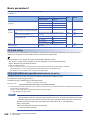
Control details
Start trigger
Major positioning control
High-level positioning control
• Turns ON the positioning start signal [Y10 to Y1F].
• Turns ON the external command signal (DI).
Home position return control
Manual control
JOG operation
Turns ON the "[Cd.181] Forward run JOG start" or the "[Cd.182] Reverse run JOG start".
Inching operation
Manual pulse generator operation
Operates the manual pulse generator.
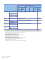
In the control other than the manual control, the following start methods can be selected.
• Normal start (Page 148 Block start)
• Multiple axes simultaneous start (Page 23 Multiple axes simultaneous start)
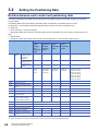
The positioning data, block start data, and condition data are used for the position specified at the control. The data that can
be used varies by the start method.
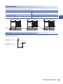
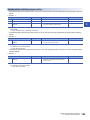
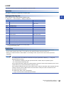
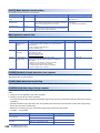
Servo ON conditions
Setting of servo parameter
PLC READY signal [Y0] ON
All axis servo ON [Y1] ON
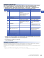
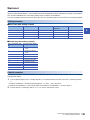
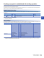
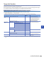
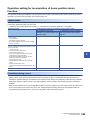
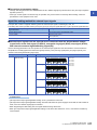
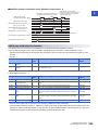
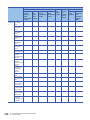
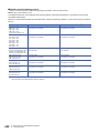
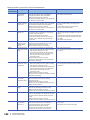
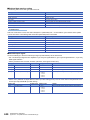
Starting conditions
To start the control, the following conditions must be satisfied.
The necessary start conditions must be incorporated in the program so that the control is not started when the conditions are
not satisfied.
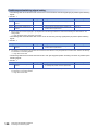
• Operation state
n: Axis No. - 1
Monitor item
Operation state
Buffer memory address
[Md.26]
"0: Standby" or "1: Stopped"
2409+100n
Axis operation status
1 START AND STOP
1.1 Start
19
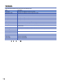
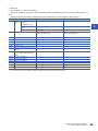
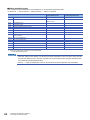
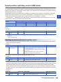
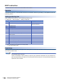
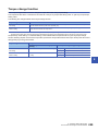
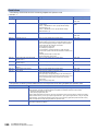
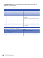
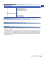
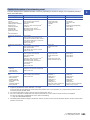
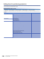
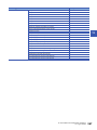
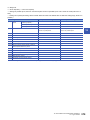
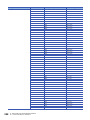
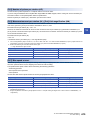
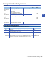
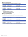
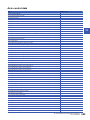
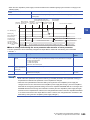
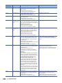
• Signal state
Signal name
I/O signal
External signal
*1
20
Signal state
Device
PLC READY signal
ON
CPU module preparation completed
Y0
READY signal
ON
RD77MS preparation completed
X0
All axis servo ON
ON
All axis servo ON
Y1
Synchronization flag*1
ON
The RD77MS buffer memory can be
accessed.
X1
Axis stop signal
OFF
Axis stop signal is OFF
[Cd.180] Axis stop
M code ON signal
OFF
M code ON signal is OFF
[Md.31] Status: b12
Error detection signal
OFF
There is no error
[Md.31] Status: b13
BUSY signal
OFF
BUSY signal is OFF
X10 to X1F
Start complete signal
OFF
Start complete signal is OFF
[Md.31] Status: b14
Forced stop input signal
ON
There is no forced stop input
Stop signal
OFF
Stop signal is OFF
Upper limit (FLS)
ON
Within limit range
Lower limit (RLS)
ON
Within limit range
The interlock must be provided so that the buffer memory is accessed after Synchronization flag [X1] turns on. When no interlock is
provided, an unexpected value may be read or written.
1 START AND STOP
1.1 Start
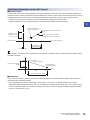
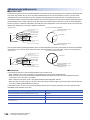
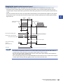
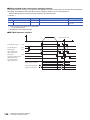
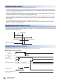
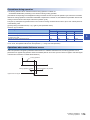
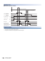
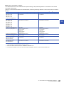
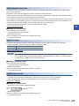
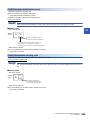
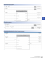
Start by the positioning start signal [Y10 to Y1F]
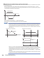
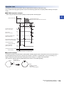
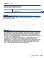
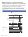
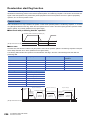
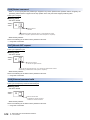
1
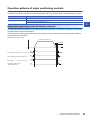
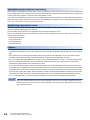
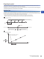
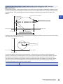
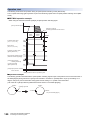
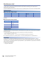
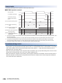
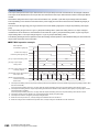
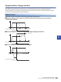
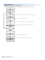
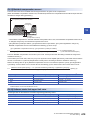
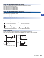
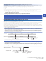
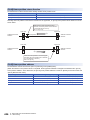
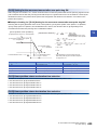
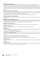
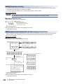
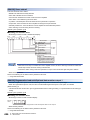
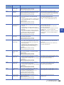
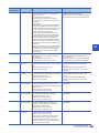
The operation at starting by the positioning start signal [Y10 to Y1F] is shown below.
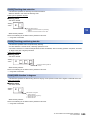
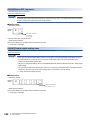
• When the positioning start signal [Y10 to Y1F] turns ON, the start complete signal ([Md.31] Status: b14) and BUSY signal
[X10 to X1F] turn ON, and the positioning operation starts. It can be seen that the axis is operating when the BUSY signal
[X10 to X1F] is ON.
• When the positioning start signal [Y10 to Y1F] turns OFF, the start complete signal ([Md.31] Status: b14) also turns OFF. If
the positioning start signal [Y10 to Y1F] is ON even after positioning is completed, the start complete signal ([Md.31] Status:
b14) will remain ON.
• If the positioning start signal turns ON again while the BUSY signal [X10 to X1F] is ON, the warning "Start during operation"
(warning code: 0900H)" will occur.
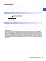
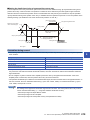
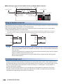
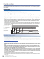
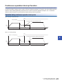
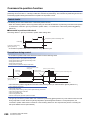
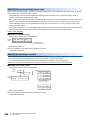
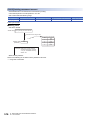
• The process executed when the positioning operation is completed will differ by whether the next positioning control is
executed.
Whether the next positioning control is
executed
Processing details
Do not execute the positioning
• If a dwell time is set, the system will wait for the set time to pass, and then positioning will be completed.
• When positioning is completed, the BUSY signal [X10 to X1F] will turn OFF and the positioning complete
signal ([Md.31] Status: b15) will turn ON. However, when using speed control or when the positioning
complete signal ON time is "0", the signal will not turn ON.
• When the time set in "[Pr.40] Positioning complete signal output time" is passed, the positioning complete
signal ([Md.31] Status: b15) will turn OFF.
Execute the positioning
• If a dwell time is set, the system will wait for the set time to pass.
• When the set dwell time is passed, the next positioning will start.
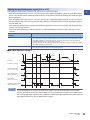
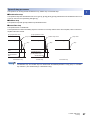
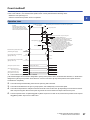
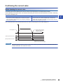
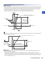
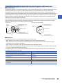
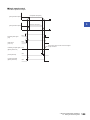
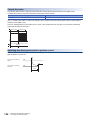
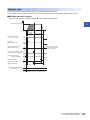
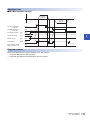
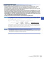
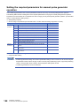
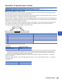
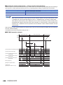
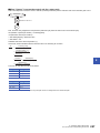
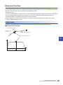
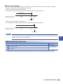
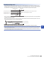
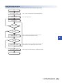
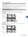
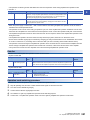
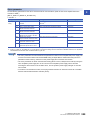
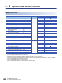
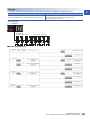
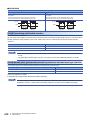
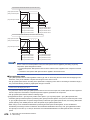
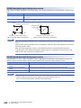
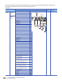
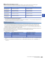
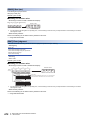
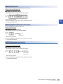
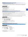
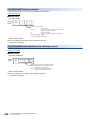
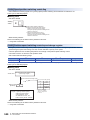
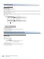
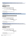
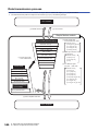
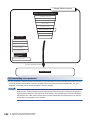
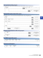
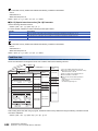
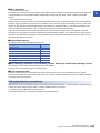
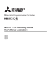
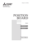
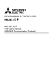
■RD77MS4 operation example
V
Dwell time
Positioning
t
ON
All axis servo ON [Y1]
OFF
ON
Positioning start signal
[Y10, Y11, Y12, Y13]
OFF
Start complete signal
([Md.31] Status: b14)
OFF
ON
ON
BUSY signal
[X10, X11, X12, X13]
OFF
ON
Positioning complete signal OFF
([Md.31] Status: b15)
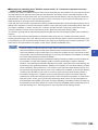
The BUSY signal [X10 to X1F] turns ON even when position control of movement amount 0 is executed.
However, since the ON time is short, the ON status may not be detected in the program. (The ON status of the
start complete signal ([Md.31] Status: b14), positioning complete signal ([Md.31] Status: b15) and M code ON
signal ([Md.31] Status: b12) can be detected in the program.)
1 START AND STOP
1.1 Start
21
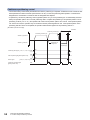
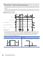
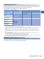
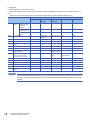
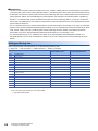
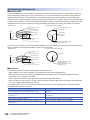
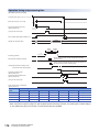
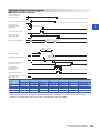
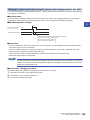
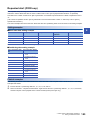
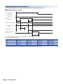
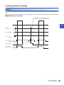
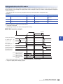
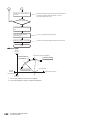
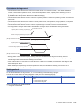
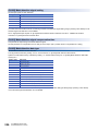
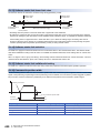
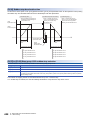
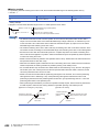
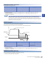
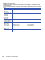
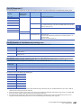
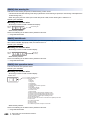
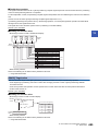
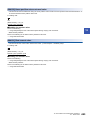
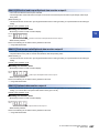
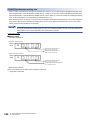
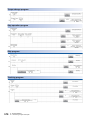
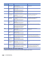
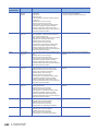
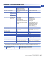
Start by the external command signal (DI)
When starting positioning control by inputting the external command signal (DI), the start command can be directly input into
the Simple Motion module. This allows the variation time equivalent to one scan time of the CPU module to be eliminated.
This is an effective procedure when operation is to be started as quickly as possible with the start command or when the
starting variation time is to be suppressed.
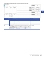
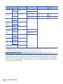
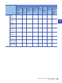
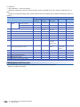
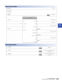
■Start method
Set "[Pr.42] External command function selection" in advance to enable "[Cd.8] External command valid" by a program. Then,
turn ON the external command signal (DI).
n: Axis No. - 1
Setting item
Setting value
Setting details
Buffer memory address
[Pr.42]
External command
function selection
0
Set to "0: External positioning start".
62+150n
[Cd.8]
External command valid
1
Set to "1: Validate external command".
4305+100n
*1
Set the external command signal (DI) to be used in "[Pr.95] External command signal".
Refer to the followings for the setting details.
Page 407 Basic Setting, Page 504 Control Data
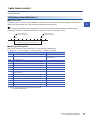
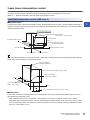
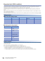
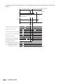
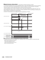
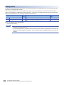
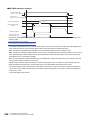
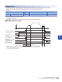
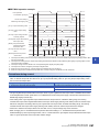
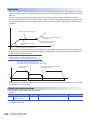
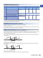
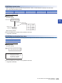
■Restriction
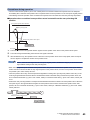
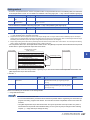
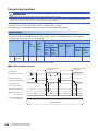
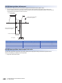
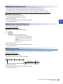
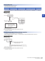
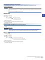
When starting by inputting the external command signal (DI), the start complete signal ([Md.31] Status: b14) will not turn ON.
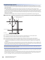
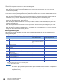
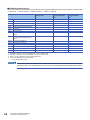
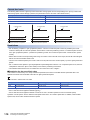
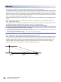
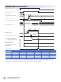
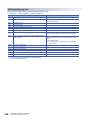
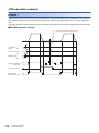
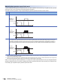
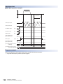
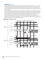
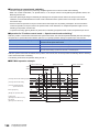
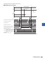
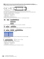
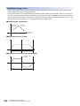
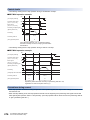
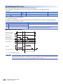
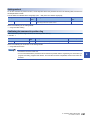
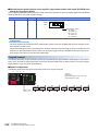
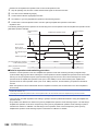
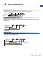
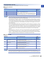
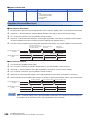
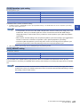
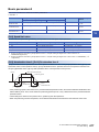
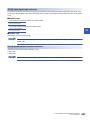
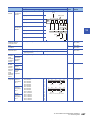
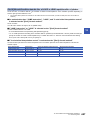
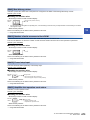
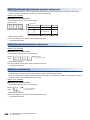
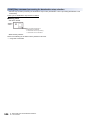
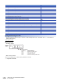
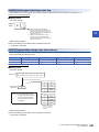
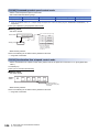
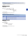
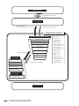
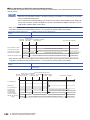
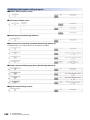
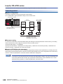
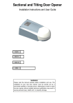
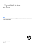
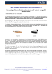
■Starting time chart
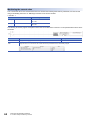
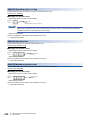
• RD77MS4 operation example
V
Operation pattern
Positioning data No.
Dwell time
1(00)
t
Positioning start signal [Y10]
All axis servo ON
[Y1]
[Md.26] Axis operation
status
Servo OFF
PLC READY signal
[Y0]
READY signal
[X0]
Standby
Start complete signal
([Md.31] Status: b14)
BUSY signal
[X10]
Positioning complete signal
([Md.31] Status: b15)
Error detection signal
([Md.31] Status: b13)
External command signal
[Pr.42] External command
function selection
0
[Cd.3] Positioning start No.
1
[Cd.8] External command
valid
22
1 START AND STOP
1.1 Start
1
0
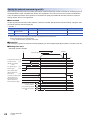
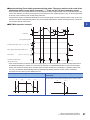
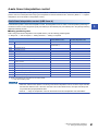
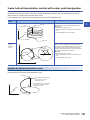
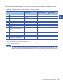
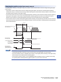
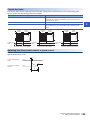
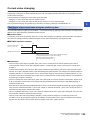
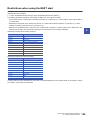
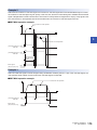
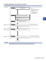
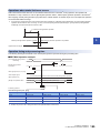
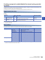
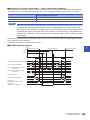
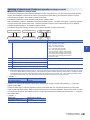
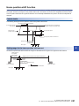
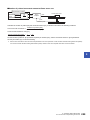
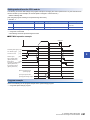
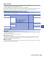
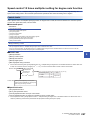
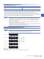
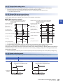
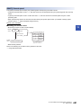
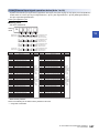
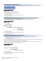
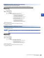
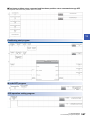
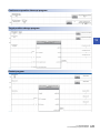
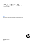
Multiple axes simultaneous start
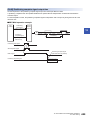
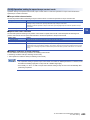
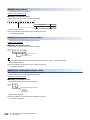
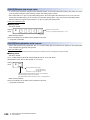
1
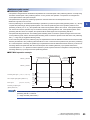
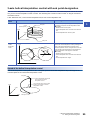
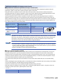
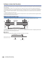
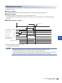
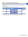
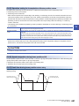
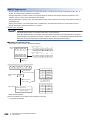
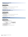
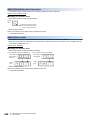
The "multiple axes simultaneous start" starts outputting the command to the specified simultaneous starting axis at the same
timing as the started axis. The maximum of four axes can be started simultaneously.
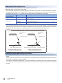
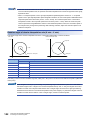
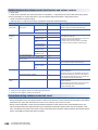
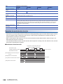
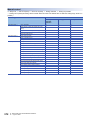
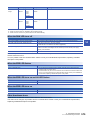
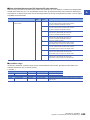
Control details
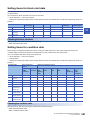
The multiple axes simultaneous start control is carried out by setting the simultaneous start setting data to the multiple axes
simultaneous start control buffer memory of the axis control data, "9004" to "[Cd.3] Positioning start No." of the start axis, and
then turning ON the positioning start signal.
Set the number of axes to be started simultaneously and axis No. in "[Cd.43] Simultaneous starting axis", and the start data
No. of simultaneous starting axis (positioning data No. to be started simultaneously for each axis) in "[Cd.30] Simultaneous
starting own axis start data No." and "[Cd.31] Simultaneous starting axis start data No.1" to "[Cd.33] Simultaneous starting
axis start data No.3".
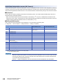
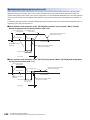
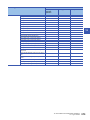
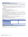
Restrictions
• The error "Error before simultaneous start" (error code: 1990H, 1991H) will occur and all simultaneously started axes will
not start if the simultaneously started axis start data No. is not set to the axis control data on the start axis or set outside the
setting range.
• The error "Error before simultaneous start" (error code: 1990H, 1991H) will occur and all simultaneously started axes will
not start if either of the simultaneously started axes is BUSY.
• The error "Error before simultaneous start" (error code: 1990H, 1991H) will occur and all simultaneously started axes will
not start if an error occurs during the analysis of the positioning data on the simultaneously started axes.
• No error or warning will occur if only the start axis is the simultaneously started axis.
• This function cannot be used with the sub function Page 266 Pre-reading start function.
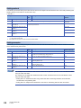
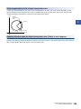
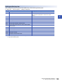
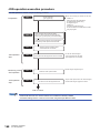
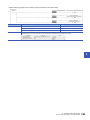
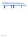
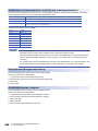
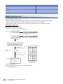
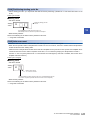
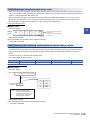
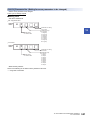
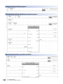
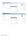
Procedure
The procedure for multiple axes simultaneous start control is shown below.
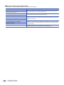
1.
Set the following axis control data.
• [Cd.43] Simultaneous starting axis
• [Cd.30] Simultaneous starting own axis start data No.
• [Cd.31] Simultaneous starting axis start data No.1
• [Cd.32] Simultaneous starting axis start data No.2
• [Cd.33] Simultaneous starting axis start data No.3
2.
3.
Write [9004] in "[Cd.3] Positioning start No.".
Turn ON the positioning start signal to be started.
1 START AND STOP
1.1 Start
23
Setting method
The following shows the setting of the data used to execute the multiple axes simultaneous start control with positioning start
signals (The axis control data on the start axis is set).
n: Axis No. - 1
Setting item
Setting
value
Setting details
Buffer memory
address
[Cd.3]
Positioning start No.
9004
Set the multiple axes simultaneous start control start No. "9004".
4300+100n
[Cd.43]
Simultaneous starting axis
Set the number of simultaneous starting axes and target axis.
4368+100n
4369+100n
[Cd.30]
Simultaneous starting own axis
start data No.
Set the simultaneously started axis start data No. Set a "0" for the axis other than the
simultaneously started axes.
4340+100n
[Cd.31]
Simultaneous starting axis start
data No.1
4341+100n
[Cd.32]
Simultaneous starting axis start
data No.2
4342+100n
[Cd.33]
Simultaneous starting axis start
data No.3
4343+100n
*1
*2
Refer to the following for the setting details.
Page 504 Control Data
The signal of axis 3 and 4 cannot be used in the RD77MS2.
Setting examples
The following shows the setting examples in which the axis 10 is used as the start axis and the axis 12 and axis 14 are used
as the simultaneously started axes.
Setting item
Setting
value
Setting details
Buffer memory
address (Axis 10)
[Cd.3]
Positioning start No.
9004
Set the multiple axes simultaneous start control start No. "9004".
5200
[Cd.43]
Simultaneous starting axis
03000D0
BH
Set the axis 12 (0BH) to the simultaneously starting axis No.1, and the axis
14 (0DH) to the simultaneously starting axis No.2.
5268, 5269
[Cd.30]
Simultaneous starting own axis
start data No.
100
The axis 10 starts the positioning data No. 100.
5240
[Cd.31]
Simultaneous starting axis start
data No.1
200
Immediately after the start of the axis 10, the axis 12 starts the axis 12
positioning data No. 200.
5241
[Cd.32]
Simultaneous starting axis start
data No.2
300
Immediately after the start of the axis 10, the axis 14 starts the axis 14
positioning data No. 300.
5242
[Cd.33]
Simultaneous starting axis start
data No.3
0
Will not start simultaneously.
5243
The "multiple axes simultaneous start control" carries out an operation equivalent to the "simultaneous start"
using the "block start data".
The setting of the "multiple axes simultaneous start control" is easier than that of the "simultaneous start"
using the "block start data".
• Setting items for "simultaneous start" using "block start data": Positioning start data, block start data,
condition data, and positioning data
• Setting items for "multiple axes simultaneous start control": Positioning data and axis control data
24
1 START AND STOP
1.1 Start
1.2
Stop
1
The axis stop signal or stop signal from external input signal is used to stop the control.
Create a program to turn ON the axis stop signal [Cd.180] as the stop program.
Each control is stopped in the following cases.
• When each control is completed normally
• When the Servo READY signal is turned OFF
• When a CPU module error occurs
• When the PLC READY signal is turned OFF
• When an error occurs in Simple Motion module
• When control is intentionally stopped (Stop signal from CPU module turned ON, "Stop signal" of external input signal turned
ON, etc.)
The stop process for the above cases is shown below.
(Excluding when each control is completed normally.)
Stop process
Stop cause
Forced stop
Stop axis
M code ON signal after
stop
Axis operation status
after stopping ([Md.26])
"Forced stop input signal" OFF
from an external device
All axes
No change
Servo OFF
Servo READY OFF
• Servo amplifier power supply
OFF
Each axis
No change
Servo amplifier has not been
connected
• Servo alarm
Error
• Forced stop input to servo
amplifier
Servo OFF
Fatal stop
(Stop group 1)
Hardware stroke limit upper/lower
limit error occurrence
Each axis
No change
Error
Emergency stop
(Stop group 2)
Error occurs in a CPU module
All axes
No change
Error
PLC READY signal OFF
Turns OFF
Error in test mode
Relatively safe
stop
(Stop group 3)
Intentional stop
(Stop group 3)
Axis error detection (Error other
than stop group 1 or 2)*1
No change
Each axis
No change
Error
Each axis
No change
Stopped
(Standby)
"Stop" input from an engineering
tool
"Axis stop signal" ON from a CPU
module
"Stop signal" of external input
signal ON
*1
If an error occurs in a positioning data due to an invalid setting value, when the continuous positioning control uses multiple positioning
data successively, it automatically decelerates at the previous positioning data. It does not stop suddenly even the setting value is
sudden stop in stop group 3. If any of the following error occurs, the operation is performed up to the positioning data immediately before
the positioning data where an error occurred, and then stops immediately.
No command speed (error code: 1A13H, 1A14H)
Outside linear movement amount range (error code: 1A15H, 1A16H)
Large arc error deviation (error code: 1A17H)
Software stroke limit + (error code: 1A18H, 1A19H)
Software stroke limit - (error code: 1A1AH, 1A1BH)
Sub point setting error (error code: 1A27H, 1A28H, 1A29H, 1A2AH, 1A37H)
End point setting error (error code: 1A2BH, 1A2CH)
Center point setting error (error code: 1A2DH, 1A2EH, 1A2FH)
Outside radius range (error code: 1A32H)
Illegal setting of ABS direction in unit of degree (error code: 19A4H, 19A5H)
1 START AND STOP
1.2 Stop
25
Stop cause
Stop process
Home position return
control
Machine
home
position
return
control
Forced stop
"Forced stop input signal" OFF
from an external device
Fast home
position
return
control
Major
positioning
control
High-level
positioning
control
Manual control
JOG/
Inching
operation
Manual
pulse
generator
operation
Servo OFF or free run
(The operation stops with dynamic brake)
Servo READY OFF
• Servo amplifier power supply
OFF
• Servo alarm
• Forced stop input to servo
amplifier
Fatal stop
(Stop group 1)
Hardware stroke limit upper/lower
limit error occurrence
Deceleration stop/sudden stop
(Select with "[Pr.37] Stop group 1 sudden stop selection".)
Deceleration
stop
Emergency stop
(Stop group 2)
Error occurs in a CPU module
Delegation stop/sudden stop
(Select with "[Pr.38] Stop group 2 sudden stop selection".)
Deceleration
stop
Deceleration stop/sudden stop
(Select with "[Pr.39] Stop group 3 sudden stop selection".)
Deceleration
stop
PLC READY signal OFF
Error in test mode
Relatively safe
stop
(Stop group 3)
Intentional stop
(Stop group 3)
Axis error detection (Error other
than stop group 1 or 2)*1
"Stop" input from an engineering
tool
"Axis stop signal" ON from a CPU
module
"Stop signal" of external input
signal ON
*1
26
If an error occurs in a positioning data due to an invalid setting value, when the continuous positioning control uses multiple positioning
data successively, it automatically decelerates at the previous positioning data. It does not stop suddenly even the setting value is
sudden stop in stop group 3. If any of the following error occurs, the operation is performed up to the positioning data immediately before
the positioning data where an error occurred, and then stops immediately.
No command speed (error code: 1A13H, 1A14H)
Outside linear movement amount range (error code: 1A15H, 1A16H)
Large arc error deviation (error code: 1A17H)
Software stroke limit + (error code: 1A18H, 1A19H)
Software stroke limit - (error code: 1A1AH, 1A1BH)
Sub point setting error (error code: 1A27H, 1A28H, 1A29H, 1A2AH, 1A37H)
End point setting error (error code: 1A2BH, 1A2CH)
Center point setting error (error code: 1A2DH, 1A2EH, 1A2FH)
Outside radius range (error code: 1A32H)
Illegal setting of ABS direction in unit of degree (error code: 19A4H, 19A5H)
1 START AND STOP
1.2 Stop
Types of stop processes
1
The operation can be stopped with deceleration stop, sudden stop or immediate stop.
■Deceleration stop
The operation stops with "deceleration time 0 to 3" ([Pr.10], [Pr.28], [Pr.29], [Pr.30]). Which time from "deceleration time 0 to 3"
to use for control is set in positioning data ([Da.4]).
■Sudden stop
The operation stops with "[Pr.36] Sudden stop deceleration time".
■Immediate stop
The operation does not decelerate.
The Simple Motion module immediately stops the command. For the stop method of the servo amplifier, refer to each servo
amplifier instruction manual.
[Pr.8] Speed limit value
[Pr.8] Speed limit value
Positioning speed
Positioning speed
Positioning speed
Stop
Stop
Actual deceleration
time
Stop cause
Sudden stop cause
Stop cause
Stop
Actual sudden stop
deceleration time
[Pr.36] Sudden stop
deceleration time
Set deceleration
time
Deceleration stop
Sudden stop
Immediate stop
"Deceleration stop" and "sudden stop" are selected with the detailed parameter 2 "stop group 1 to 3 sudden
stop selection". (The default setting is "deceleration stop".)
1 START AND STOP
1.2 Stop
27
Order of priority for stop process
The order of priority for the Simple Motion module stop process is as follows.
(Deceleration stop) < (Sudden stop) < (Servo OFF)
• If the deceleration stop command ON (stop signal ON) or deceleration stop cause occurs during deceleration to speed 0
(including automatic deceleration), operation changes depending on the setting of "[Cd.42] Stop command processing for
deceleration stop selection". (Page 269 Stop command processing for deceleration stop function)
Positioning control
during deceleration
Setting value of [Cd.42]
Processing details
Manual control
Independently of the [Cd.42] setting, a deceleration curve is re-processed from the speed at
stop cause occurrence.
Home position return control,
positioning control
0: Deceleration curve reprocessing
A deceleration curve is re-processed from the speed at stop cause occurrence. (Page 269
Deceleration curve re-processing)
1: Deceleration curve
continuation
The current deceleration curve is continued after stop cause occurrence. (Page 269
Deceleration curve continuation)
• If the stop signal designated for sudden stop turns ON or a stop cause occurs during deceleration, the sudden stop process
will start from that point. However, if the sudden stop deceleration time is longer than the deceleration time, the deceleration
stop process will be continued even if a sudden stop cause occurs during the deceleration stop process.
Example
The process when a sudden stop cause occurs during deceleration stop is shown below.
Positioning speed
Deceleration stop
process
Positioning speed
Sudden stop cause
Sudden stop cause
Stop
Sudden stop deceleration process
Deceleration stop
process
Stop
Deceleration stop process continues
(a) When deceleration stop time >
sudden stop deceleration time
Process for sudden stop
(b) When deceleration stop time <
sudden stop deceleration time
Inputting the stop signal during deceleration
• Even if stop is input during deceleration (including automatic deceleration), the operation will stop at that deceleration
speed.
• If stop is input during deceleration for home position return, the operation will stop at that deceleration speed. If input at the
creep speed, the operation will stop immediately.
• If a stop cause, designated for sudden stop, occurs during deceleration, the sudden stop process will start from that point.
The sudden stop process during deceleration is carried out only when the sudden stop time is shorter than the deceleration
stop time.
28
1 START AND STOP
1.2 Stop
1.3
Restart
1
When a stop factor occurs during position control and the operation stops, the positioning can be restarted from the stopped
position to the position control end point by using the "restart command" ([Cd.6] Restart command). ("Restarting" is not
possible when "continuous operation is interrupted.")
This instruction is efficient when performing the remaining positioning from the stopped position in the positioning control of
incremental method such as INC linear 1. (Calculation of remaining distance is not required.)
Operation
After a deceleration stop by the stop command is completed, write "1: Restarts" to the "[Cd.6] Restart command" with "[Md.26]
Axis operation status" is "stopped" and the positioning restarts.
V
Start
Positioning data No.11
continues with restart command
Stop process with
stop command
t
Positioning data No.10
Positioning data No.11
Positioning data No.12
Restrictions
• Restarting can be executed only when the "[Md.26] Axis operation status" is "stopped (the deceleration stop by stop
command is completed)". If the axis operation is not "stopped", restarting is not possible. In this case, the warning "Restart
not possible" (warning code: 0902H) will occur, and the process at that time will be continued.
• Do not execute restart while the stop command is ON. If restart is executed while stopped, the error "Stop signal ON at
start" (error code: 1908H) will occur, and the "[Md.26] Axis operation status" will change to "Error". Thus, even if the error is
reset, the operation cannot be restarted.
• Restarting can be executed even while the positioning start signal is ON. However, make sure that the positioning start
signal does not change from OFF to ON while stopped.
• If the positioning start signal is changed from OFF to ON while "[Md.26] Axis operation status" is "stopped", the normal
positioning (the positioning data set in "[Cd.3] Positioning start No.") is started.
• If positioning is ended with the continuous operation interrupt request, the operation cannot be restarted. If restart is
requested, the warning "Restart not possible" (warning code: 0902H) will occur.
• When stopped with interpolation operation, write "1: Restarts" into "[Cd.6] Restart command" for the reference axis, and
then restart.
• If the PLC READY signal is changed from OFF to ON while stopped, restarting is not possible. If restart is requested, the
warning "Restart not possible" (warning code: 0902H) will occur.
• When the machine home position return and fast home position return is stopped, the error "Home position return restart
not possible" (error code: 1946H) will occur and the positioning cannot restarts.
• If any of reference partner axes executes the positioning operation once after interpolation operation stop, the warning
"Restart not possible" (warning code: 0902H) will occur, and the positioning cannot restarts.
Setting method
Set the following data to execute restart.
n: Axis No. - 1
Setting item
Setting
value
Setting details
Buffer memory address
[Cd.6]
1
Set "1: Restarts".
4303+100n
*1
Restart command
Refer to the following for the setting details.
Page 504 Control Data
1 START AND STOP
1.3 Restart
29
Time chart for restarting
■RD77MS4 operation example
V
Dwell time
t
Positioning start signal
[Y10]
[Cd.180] Axis stop
All axis servo ON
[Y1]
PLC READY signal
[Y0]
READY signal
[X0]
Start complete signal
([Md.31] Status: b14)
BUSY signal
[X10]
Positioning complete signal
([Md.31] Status: b15)
Error detection signal
([Md.31] Status: b13)
[Md.26] Axis operation status
0
[Cd.6] Restart command
Program example
Refer to the following for the program example of restart.
Page 571 Restart program
30
1 START AND STOP
1.3 Restart
8
0
8
1
1
0
0
2
HOME POSITION RETURN CONTROL
The details and usage of "home position return control" are explained in this chapter.
2.1
2
Outline of Home Position Return Control
Two types of home position return control
In "home position return control", a position is established as the starting point (or "home position") when carrying out
positioning control, and positioning is carried out toward that starting point.
It is used to return a machine system at any position other than the home position to the home position when the Simple
Motion module issues a "home position return request" with the power turned ON or others, or after a positioning stop.
In the Simple Motion module, the following two control types are defined as "home position return control", following the flow
of the home position return work. These two types of home position return control can be executed by setting the "home
position return parameters", setting "Positioning start No. 9001" and "positioning start No. 9002" prepared beforehand in the
Simple Motion module to "[Cd.3] Positioning start No.", and turning ON the positioning start signal.
Home position return method
Home position return method operation details
Machine home position return
(positioning start No. 9001)
Executes the home position return operation to establish a machine home position. The following positioning control
is executed based on the home position established by the home position return completion. The machine home
position return is required when the machine home position has not been established (the current value monitor of
the Simple Motion module and the actual machine position are not matched) due to the power supply ON of the
system, etc.
Fast home position return (positioning
start No. 9002)
Executes the positioning to the home position established by a machine home position return. The fast home
position return is operated by specifying the positioning start No.9002, so that the positioning which returns to the
home position can be executed without setting the positioning data.
The "machine home position return" above must be carried out in advance to execute the "fast home position return".
CAUTION
• When using an absolute position system, execute a home position return always at the following cases: on starting up and when the controller or absolute
value motor has been replaced. Check the home position return request signal using the program, etc. before performing the positioning control. Failure to
observe this could lead to an accident such as a collision.
The address information stored in the Simple Motion module cannot be guaranteed while the "home position return request
flag" is ON.
The "home position return request flag" turns OFF and the "home position return complete flag" ([Md.31] Status: b4) turns ON
if the machine home position return is executed and is completed normally.
The "home position return request flag" ([Md.31] Status: b3) must be turned ON in the Simple Motion module, and a machine
home position return must be executed in the following cases.
When not using an absolute position system
• This flag turns on in the following cases:
• System's power supply on or reset
• Servo amplifier power supply on
• Machine home position return start (Unless a machine home position return is completed normally, the
home position return request flag does not turn off.)
• This flag turns off by the completion of machine home position return.
2 HOME POSITION RETURN CONTROL
2.1 Outline of Home Position Return Control
31
When using an absolute position system
• This flag turns on in the following cases:
• When not executing a machine home position return even once after the system starts
• Machine home position return start (Unless a machine home position return is completed normally, the home position return request flag does not turn off.)
• When an absolute position data in the Simple Motion module is erased due to a battery error, etc. (occurrence of the warning "Home position return data
incorrect" (warning code: 093CH))
• When the "Rotation direction selection/travel direction selection (PA14)" of servo parameter is changed.
• The servo alarm "Absolute position erased" (alarm No.: 25) occurs. ([Md.108] Servo status1: b14 ON)
• The servo warning "Absolute position counter warning" (warning No.: E3) occurs. ([Md.108] Servo status1: b14 ON)
n: Axis No. - 1
Monitor item
Buffer memory address
[Md.108] Servo status1: b14
2477+100n
• This flag turns off by the completion of the machine home position return.
Wiring the near-point dog
The "external input signal of the Simple Motion module", "external input signal of the servo amplifier" or "buffer memory of the
Simple Motion module" can be selected by "[Pr.118] DOG signal selection" as the near-point dog.
When the "buffer memory of the Simple Motion module" is selected, the wiring differs according to the Input module used. As
for the 24 V DC power supply, the direction of current can be switched.
*1
When "Servo amplifier" is set in "[Pr.116] FLS signal selection" to "[Pr.118] DOG signal selection" at MR-JE-B use, any errors or
warnings do not occur. However, the external input signal (upper/lower limit signal, near-point dog signal) cannot be operated.
Simple Motion
module
Servo amplifier
DOG
DI3
(DOG)
DICOM
COM
24 V DC
24 V DC
Home position return sub functions
Refer to the following for details on "sub functions" that can be combined with home position return control.
MELSEC iQ-R Simple Motion Module User's Manual (Startup)
Also refer to the following for details on each sub function.
Page 215 CONTROL SUB FUNCTIONS
[Remarks]
The following two sub functions are only related to machine home position return.
: Combination possible, : Restricted, : Combination not possible
Sub function name
Machine home position return
Fast home position return
Reference
Home position return retry function
Page 217 Home position return retry
function
Home position shift function
Page 221 Home position shift function
When a home position return is not required
Control can be carried out ignoring the "home position return request flag" ([Md.31] Status: b3) in systems that do not require
a home position return.
In this case, the "home position return parameters ([Pr.43] to [Pr.57])" must all be set to their initial values or a value at which
an error does not occur.
32
2 HOME POSITION RETURN CONTROL
2.1 Outline of Home Position Return Control
2.2
Machine Home Position Return
Outline of the machine home position return operation
2
Use the home position return retry function when the home position is not always in the same direction from
the workpiece operation area (when the home position is not set near the upper or lower limit of the machine).
The machine home position return may not complete unless the home position return retry function is used.
Machine home position return operation
In a machine home position return, a home position is established.
None of the address information stored in the Simple Motion module, CPU module, or servo amplifier is used at this time.
The position mechanically established after the machine home position return is regarded as the "home position" to be the
starting point for positioning control.
The method for establishing a home position by a machine home position return differs according to the method set in "[Pr.43]
Home position return method".
The following shows the operation when starting a machine home position return.
M
Home position
Machine home position return
Near-point dog
1.
2.
3.
The "machine home position return" is started.
The operation starts according to the speed and direction set in the home position return parameters ([Pr.43] to [Pr.57]).
The "home position" is established by the method set in "[Pr.43] Home position return method", and the machine stops.
Page 34 Machine home position return method to Page 42 Scale origin signal detection method
4.
If "a" is set as "[Pr.45] Home position address", "a" will be stored as the current position in the "[Md.20] Current feed
value" and "[Md.21] Machine feed value" which are monitoring the position.
5.
The machine home position return is completed.
2 HOME POSITION RETURN CONTROL
2.2 Machine Home Position Return
33
Machine home position return method
The method by which the machine home position is established (method for judging the home position and machine home
position return completion) is designated in the machine home position return according to the configuration and application of
the positioning method.
The following table shows the methods that can be used for this home position return method. (The home position return
method is one of the items set in the home position return parameters. It is set in "[Pr.43] Home position return method" of the
basic parameters for home position return.)
[Pr.43] Home position return
method
Operation details
Near-point dog method
Deceleration starts by the OFF ON of the near-point dog. (Speed is reduced to "[Pr.47] Creep speed".)
The operation stops once after the near-point dog turns ON and then OFF. Later the operation restarts and then stops
at the first zero signal to complete the home position return.
That position is assumed as a home position.
Count method 1
The deceleration starts by the OFF ON of the near-point dog, and the machine moves at the "[Pr.47] Creep speed".
The machine stops once after moving the distance set in the "[Pr.50] Setting for the movement amount after nearpoint dog ON" from the OFF ON position. Later the operation restarts and then stops at the first zero point to
complete the machine home position return.
Count method 2
The deceleration starts by the OFF ON of the near-point dog, and the machine moves at the "[Pr.47] Creep speed.
The machine moves the distance set in the "[Pr.50] Setting for the movement amount after near-point dog ON" from
the near-point dog OFF ON position, and stops at that position. The machine home position return is then regarded
as completed.
Data set method
The position where the machine home position return has been performed becomes a home position.
The current feed value and feed machine value are overwritten to the home position address.
Scale origin signal detection method
The machine moves in the opposite direction against of "[Pr.44] Home position return direction" at the "[Pr.46] Home
position return speed" by the OFF ON of the near-point dog, and a deceleration stop is carried out once at the first
zero signal. Later the operation moves in direction of "[Pr.44] Home position return direction" at the "[Pr.47] Creep
speed", and then stops at the detected nearest zero point to complete the machine home position return.
The following shows the signals used for machine home position return.
: Necessary, : Necessary as required, : Unnecessary
[Pr.43] Home position return
method
Signals required for control
Near-point dog
Zero signal
Upper/lower limit
Near-point dog method
Count method 1
Count method 2
Data set method
Scale origin signal detection method
Creep speed
The stopping accuracy is poor when the machine suddenly stops from fast speeds. To improve the machine's
stopping accuracy, it is required to slow down the speed before it stops. This speed is set in the "[Pr.47] Creep
speed".
34
2 HOME POSITION RETURN CONTROL
2.2 Machine Home Position Return
Near-point dog method
The following shows an operation outline of the home position return method "near-point dog method".
Operation chart
V
[Pr.46] Home position
return speed
2
Deceleration at the near-point dog ON
[Pr.47] Creep speed
[POINT]
After the home position return
has been started, the zero point
of the encoder must be passed at
least once before point A is reached.
1.
2.
3.
A
4. 5.
t
[Md.34] Movement amount after near-point dog ON*1
ON
Near-point dog OFF
Zero signal
Adjust so the near-point dog OFF
position is as close as possible to the
center of the zero signal HIGH level.
If the near-point dog OFF position
overlaps with the zero signal,
the machine home position return stop
position may deviate by one servomotor
rotation.
One servo motor rotation
ON
Machine home position return start
(Positioning start signal)
OFF
Home position return request flag
([Md.31] Status: b3)
OFF
Home position return complete flag
([Md.31] Status: b4)
OFF
ON
ON
[Md.26] Axis operation status
[Md.34] Movement amount after
near-point dog ON
[Md.20] Current feed value
[Md.21] Machine feed value
1.
Standby
Inconsistent
Inconsistent
Home position return
Standby
0
Value of *1
Value of the machine moved is stored
Home position address
The machine home position return is started.
(The machine begins the acceleration designated in "[Pr.51] Home position return acceleration time selection", in the direction
designated in "[Pr.44] Home position return direction". It then moves at the "[Pr.46] Home position return speed" when the
acceleration is completed.)
2.
3.
The machine begins decelerating when the near-point dog ON is detected.
The machine decelerates to the "[Pr.47] Creep speed", and subsequently moves at that speed.
(At this time, the near-point dog must be ON. The workpiece will continue decelerating and stop if the near-point dog is OFF.)
4.
5.
After the near-point dog turns OFF, the machine stops. It then restarts and stops at the first zero point.
The home position return complete flag ([Md.31] Status: b4) turns from OFF to ON and the home position return request
flag ([Md.31] Status: b3) turns from ON to OFF.
2 HOME POSITION RETURN CONTROL
2.2 Machine Home Position Return
35
Precautions during operation
• When the home position return retry function is not set ("0" is set in "[Pr.48] Home position return retry"), the error "Start at
home position" (error code: 1940H) will occur if the machine home position return is attempted again after the machine
home position return completion.
• Machine home position return carried out from the near-point dog ON position will start at the "[Pr.47] Creep speed".
• The near-point dog must be ON during deceleration from the home position return speed "[Pr.47] Creep speed".
• When the stop signal stops the machine home position return, carry out the machine home position return again. When
restart command is turned ON after the stop signal stops the home position return, the error "Home position return restart
not possible" (error code: 1946H) will occur.
• After the home position return has been started, the zero point of the encoder must be passed at least once before point A
is reached. However, if selecting "1: Not need to pass servo motor Z-phase after power on" with "Function selection C-4
(PC17)", it is possible to carry out the home position return without passing the zero point. The workpiece will continue
decelerating and stop if the near-point dog is turned OFF before it has decelerated to the creep speed, thus causing the
error "Dog detection timing fault" (error code: 1941H).
V
[Pr.46] Home position return speed
[Pr.47] Creep speed
t
ON
Near-point dog OFF
ON
Machine home position return start
(Positioning start signal)
OFF
ON
Home position return request flag
([Md.31] Status: b3)
OFF
Home position return complete flag
([Md.31] Status: b4)
OFF
[Md.26] Axis operation status
[Md.34] Movement amount
after near-point dog ON
[Md.20] Current feed value
[Md.21] Machine feed value
36
Standby
Inconsistent
Home position return
Error
0
Inconsistent
2 HOME POSITION RETURN CONTROL
2.2 Machine Home Position Return
Value of the machine moved is stored
Address at stop
Count method1
The following shows an operation outline of the home position return method "count method 1".
In the "count method 1", the machine home position return can be performed in the following cases:
• Where the near-point dog is on
2
• After the machine home position return is completed
Operation chart
[POINT]
After the home position return
has been started, the zero point
of the encoder must be passed at
least once before point A is reached.
V
[Pr.46] Home position
return speed
[Pr.50] Setting for the movement amount after near-point dog ON
[Pr.47] Creep speed
t
A
[Md.34] Movement amount after near-point dog ON*1
Leave sufficient distance from
the home position to the near-point dog OFF.
ON
Adjust the setting for the movement amount
after near-point dog ON to be as near as possible
to the center of the zero signal HIGH.
If the setting for the movement amount after
near-point dog ON falls within the zero signal,
there may be produced an error of one servo motor
rotation in the home position return stop position.
Near-point dog OFF
Zero signal
First zero signal after moving a set to
"[Pr.50] Setting for the movement
amount after near-point dog ON.
One servo motor rotation
ON
Machine home position return start
(Positioning start signal)
OFF
Home position return request flag
([Md.31] Status: b3)
OFF
Home position return complete flag
([Md.31] Status: b4)
OFF
ON
ON
Standby Home position return
[Md.26] Axis operation status
[Md.34] Movement amount
after near-point dog ON
Standby
Inconsistent
0
Value of *1
Inconsistent
Value of the machine moved is stored
Home position address
[Md.20] Current feed value
[Md.21] Machine feed value
1.
The machine home position return is started.
(The machine begins the acceleration designated in "[Pr.51] Home position return acceleration time selection", in the direction
designated in "[Pr.44] Home position return direction". It then moves at the "[Pr.46] Home position return speed" when the
acceleration is completed.)
2.
3.
4.
The machine begins decelerating when the near-point dog ON is detected.
The machine decelerates to the "[Pr.47] Creep speed", and subsequently moves at that speed.
The machine stops after the workpiece has been moved the amount set in the "[Pr.50] Setting for the movement amount
after near-point dog ON" after the near-point dog turned ON. It then restarts and stops at the first zero point.
5.
The home position return complete flag ([Md.31] Status: b4) turns from OFF to ON, and the home position return request
flag ([Md.31] Status: b3) turns from ON to OFF.
2 HOME POSITION RETURN CONTROL
2.2 Machine Home Position Return
37
Precautions during operation
• The error "Count method movement amount fault" (error code: 1944H) will occur if the "[Pr.50] Setting for the movement
amount after near-point dog ON" is smaller than the deceleration distance from the "[Pr.46] Home position return speed" to
"[Pr.47] Creep speed".
• If the speed is changed to a speed faster than "[Pr.46] Home position return speed" by the speed change function
(Page 248 Speed change function) during a machine home position return, the distance to decelerate to "[Pr.47] Creep
speed" may not be ensured, depending on the setting value of "[Pr.50] Setting for the movement amount after near-point
dog ON". In this case, the error "Count method movement amount fault" (error code: 1944H) occurs and the machine home
position return is stopped.
• The following shows the operation when a machine home position return is started while the near-point dog is ON.
■Operation when a machine home position return is started at the near-point dog ON position
[Pr.50] Setting for the movement amount
after near-point dog ON
4.
1.
5.
3.
2.
ON
Near-point dog
OFF
Zero signal
1.
2.
3.
4.
5.
A machine home position return is started.
The machine moves at the home position return speed in the opposite direction of a home position return.
Deceleration processing is carried out when the near-point dog OFF is detected.
After the machine stops, a machine home position return is carried out in the home position return direction.
The machine home position return is completed on detection of the first zero signal after the travel of the movement
amount set to "[Pr.50] Setting for the movement amount after near-point dog ON" on detection of the near-point dog
signal ON.
• Turn OFF the near-point dog at a sufficient distance from the Home position. Although there is no harm in operation if the
near-point dog is turned OFF during a machine home position return, it is recommended to leave a sufficient distance from
the home position when the near-point dog is turned OFF for the following reason.
If the machine home position return is performed consecutively after the near-point dog is turned OFF at the time of machine home position return completion,
operation will be performed at the home position return speed until the hardware stroke limit (upper/lower limit) is reached. If a sufficient distance cannot be
kept, consider the use of the home position return retry function.
• When the stop signal stops the machine home position return, carry out the machine home position return again. When
restart command is turned ON after the stop signal stops the home position return, the error "Home position return restart
not possible" (error code: 1946H) will occur.
• After the home position return has been started, the zero point of the encoder must be passed at least once before point A
is reached. However, if selecting "1: Not need to pass servo motor Z-phase after power on" with "Function selection C-4
(PC17)", it is possible to carry out the home position return without passing the zero point.
38
2 HOME POSITION RETURN CONTROL
2.2 Machine Home Position Return
Count method2
The following shows an operation outline of the home position return method "count method 2".
The "count method 2" method is effective when a "zero signal" cannot be received. (Note that compared to the "count method
1" method, using this method will result in more deviation in the stop position during machine home position return.)
2
Operation chart
V
[Pr.46] Home position
return speed
[Pr.50] Setting for the movement amount
after near-point dog ON
[Pr.47] Creep speed
t
[Md.34] Movement amount after near-point dog ON*1
Leave sufficient distance from
the home position to the near-point
dog OFF.
ON
Near-point dog OFF
ON
Machine home position return start
(Positioning start signal)
OFF
ON
Home position return request flag
([Md.31] Status: b3)
OFF
ON
Home position return complete flag
([Md.31] Status: b4)
[Md.26] Axis operation status
[Md.34] Movement amount
after near-point dog ON
[Md.20] Current feed value
[Md.21] Machine feed value
1.
OFF
Standby
Home position return
Standby
Inconsistent
0
Value of *1
Inconsistent
Value of the machine moved is stored
Home position address
The machine home position return is started.
(The machine begins the acceleration designated in "[Pr.51] Home position return acceleration time selection", in the direction
designated in "[Pr.44] Home position return direction". It then moves at the "[Pr.46] Home position return speed" when the
acceleration is completed.)
2.
3.
4.
The machine begins decelerating when the near-point dog ON is detected.
The machine decelerates to the "[Pr.47] Creep speed", and subsequently moves at that speed.
The command from the Simple Motion module will stop and the machine home position return will be completed when
the machine moves the movement amount set in "[Pr.50] Setting for the movement amount after near-point dog ON"
from the near-point dog ON position.
Restrictions
When this method is used, a deviation will occur in the stop position (home position) compared to other home position return
methods because an error occurs in taking in the near-point dog ON. The error varies by the input type of "[Pr.118] DOG
signal selection".
The taking error by the input type is shown below.
10 [s] when setting "0: Simple Motion module"
The operation cycle when setting "1: Servo amplifier"
The operation cycle + scan time when setting "2: Buffer memory"
2 HOME POSITION RETURN CONTROL
2.2 Machine Home Position Return
39
Precautions during operation
• The error "Count method movement amount fault" (error code: 1944H) will occur and the operation will not start if the
"[Pr.50] Setting for the movement amount after near-point dog ON" is smaller than the deceleration distance from the
"[Pr.46] Home position return speed" to "[Pr.47] Creep speed".
• If the speed is changed to a speed faster than "[Pr.46] Home position return speed" by the speed change function
(Page 248 Speed change function) during a machine home position return, the distance to decelerate to "[Pr.47] Creep
speed" may not be ensured, depending on the setting value of "[Pr.50] Setting for the movement amount after near-point
dog ON". In this case, the error "Count method movement amount fault" (error code: 1944H) occurs and the machine home
position return is stopped.
• The following shows the operation when a machine home position return is started while the near-point dog is ON.
■Operation when a home position return is started at the near-point dog ON position
[Pr.50] Setting for the movement amount
after near-point dog ON
4.
1.
5.
3.
2.
ON
Near-point dog
1.
2.
3.
4.
5.
OFF
A machine home position return is started.
The machine moves at the home position return speed in the opposite direction of a home position return.
Deceleration processing is carried out when the near-point dog OFF is detected.
After the machine stops, a machine home position return is carried out in the home position return direction.
The machine home position return is completed after moving the movement amount set in the "[Pr.50] Setting for the
movement amount after near-point dog ON".
• Turn OFF the near-point dog at a sufficient distance from the home position. Although there is no harm in operation if the
near-point dog is turned OFF during a machine home position return, it is recommended to leave a sufficient distance from
the home position when the near-point dog is turned OFF for the following reason.
If the machine home position return is performed consecutively after the near-point dog is turned OFF at the time of machine home position return completion,
operation will be performed at the home position return speed until the hardware stroke limit (upper/lower limit) is reached. If a sufficient distance cannot be
kept, consider the use of the home position return retry function.
• When the stop signal stops the machine home position return, carry out the machine home position return again. When
restart command is turned ON after the stop signal stops the home position return, the error "Home position return restart
not possible" (error code: 1946H) will occur.
40
2 HOME POSITION RETURN CONTROL
2.2 Machine Home Position Return
Data set method
The following shows an operation outline of the home position return method "data set method".
The "Data set method" method is effective when a "Near-point dog" is not used. It can be used with absolute position system.
With the data set method home position return, the position where the machine home position return has been carried out, is
2
registered into the Simple Motion module as the home position, and the current feed value and feed machine value is
overwritten to a home position address.
Use the JOG or manual pulse generator operation to move the home position.
Operation chart
The address upon execution of the
home position return is registered
as a home position address.
t
Home position
return start
Precautions during operation
• The zero point must have been passed before the home position return is carried out after the power supply is turned ON.
If the home position return is carried out without passing the zero point even once, the error "Home position return zero
point not passed" (error code: 197AH) will occur. When the error "Home position return zero point not passed" (error code:
197AH) occurs, perform the JOG or similar operation so that the servomotor makes more than one revolution after an error
reset, before carrying out the machine home position return again. However, if selecting "1: Not need to pass servo motor
Z-phase after power on" with "Function selection C-4 (PC17)", it is possible to carry out the home position return without
passing the zero point.
• The home position return data used for the data set method is the "home position return direction" and "home position
address". The home position return data other than that for the home position return direction and home position address is
not used for the data set method home position return method, but if a value is set the outside the setting range, an error
will occur when the PLC READY signal [Y0] is turned ON so that the READY signal [X0] is not turned OFF. With the home
position return data other than that for the home position return direction and home position address, set an arbitrary value
(default value can be allowed) within each data setting range so that an error will not occur upon receiving the PLC READY
signal [Y0] ON.
2 HOME POSITION RETURN CONTROL
2.2 Machine Home Position Return
41
Scale origin signal detection method
The following shows an operation outline of the home position return method "scale origin signal detection method".
Set "0: Need to pass servo motor Z-phase after power on" in "Function selection C-4 (PC17)". If "1: Not need
to pass servo motor Z-phase after power on" is set, the error "Z-phase passing parameter invalid" (error code:
1978H) will occur at the start of scale origin signal detection method home position return.
Operation chart
V
[Pr.44] Home position return direction
[Pr.46] Home position return speed
2.
[Pr.47] Creep speed
1.
5.
6.
3.
4.
ON
Near-point dog OFF
Hardware limit switch
Zero signal
1.
The machine home position return is started.
(The machine begins the acceleration designated in "[Pr.51] Home position return acceleration time selection", in the direction
designated in "[Pr.44] Home position return direction". It then moves at the "[Pr.46] Home position return speed" when the
acceleration is completed.)
2.
3.
The machine begins decelerating when the near-point dog ON is detected.
After deceleration stop, the machine moves in the opposite direction against of home position return at the "[Pr.46] Home
position return speed".
4.
5.
During movement, the machine begins decelerating when the first zero signal is detected.
After deceleration stop, the operation moves in direction of home position return at the "[Pr.47] Creep speed", and then
stops at the detected nearest zero signal.
6.
The home position return complete flag ([Md.31] Status: b4) turns from OFF to ON, and the home position return request
flag ([Md.31] Status: b3) turns from ON to OFF.
After 3., when the zero signal is in the near-point dog position, deceleration stop (4.) is started at the zero
signal without waiting for the near-point dog OFF.
42
2 HOME POSITION RETURN CONTROL
2.2 Machine Home Position Return
Precautions during operation
• The error "Start at home position" (error code: 1940H) will occur if another machine home position return is attempted
immediately after a machine home position return completion when the home position is in the near-point dog ON position.
• The following shows the operation when a machine home position return is started from the near-point dog ON position.
2
■Operation when a machine home position return is started from the near-point dog ON
position
V
[Pr.44] Home position return direction
[Pr.47] Creep speed
3.
1.
2.
ON
[Pr.46] Home position return speed
Near-point dog OFF
Hardware limit switch
Zero signal
1.
2.
3.
The machine moves in the opposite direction against of home position return at the home position return speed.
The machine begins decelerating when the first zero signal is detected.
After deceleration stop, the operation moves in direction of home position return at the creep speed, and then stops at
the zero signal to complete the machine home position return.
After 1., when the zero signal is in the near-point dog ON position, deceleration stop (2.) is started at the zero
signal without waiting for the near-point dog OFF.
• When the stop signal stops the machine home position return, carry out the machine home position return again. When
restart command is turned ON after the stop signal stops the home position return, the error "Home position return restart
not possible" (error code: 1946H) will occur.
• The home position return retry will not be performed regardless of setting set in "[Pr.48] Home position return retry" in the
scale origin signal detection method. When a hardware limit switch is detected during machine home position return, the
error "Hardware stroke limit (+)" (error code: 1904H, 1905H) or "Hardware stroke limit (-)" (error code: 1906H, 1907H) will
occur.
• Position the near-point dog forward to overlaps with the hardware limit switch in direction of home position return. When the
near-point dog is in the opposite direction against of home position return from the machine home position return start
position, the error "Hardware stroke limit (+)" (error code: 1904H, 1905H) or "Hardware stroke limit (-)" (error code: 1906H,
1907H) will occur.
M
Home position
Machine home position return
Near-point dog
Hardware limit switch
2 HOME POSITION RETURN CONTROL
2.2 Machine Home Position Return
43
• When the zero signal is detected again during deceleration (4.) in the following figure) with detection of zero signal, the
operation stops at the zero signal detected lastly to complete the home position return.
V
[Pr.44] Home position return direction
[Pr.46] Home position return speed
2.
[Pr.47] Creep speed
6.
1.
5.
3.
4.
ON
Near-point dog OFF
Zero signal
• Do not use the scale origin signal detection method home position return for the machine with the backlash.
• When using the direct drive motor, make it passed the Z phase once before reaching 3. in the previous operation chart.
(Page 42 Scale origin signal detection method)
44
2 HOME POSITION RETURN CONTROL
2.2 Machine Home Position Return
2.3
Fast Home Position Return
Outline of the fast home position return operation
2
Fast home position return operation
After establishing home position by a machine home position return, positioning control to the home position is executed
without using a near-point dog or a zero signal.
The following shows the operation during a basic fast home position return start.
[Pr.46] Home position return speed
Machine home position
(Home position)
Fast home position return start
(Positioning start signal)
[Md.26] Axis operation status
Standby
Position control
Standby
M
Home position
Positioning to the home position
1.
2.
The fast home position return is started.
Positioning control to the home position established by a machine home position return begins at speed set in the home
position return parameters ([Pr.43] to [Pr.57]).
3.
The fast home position return is completed.
Operation timing and processing time
The following shows details about the operation timing and time during fast home position return.
[RD77MS4 operation example]
Positioning start signal
[Y10, Y11, Y12, Y13]
BUSY signal
[X10, X11, X12, X13]
t1
Start complete signal
([Md.31] Status: b14)
t3
[Md.26] Axis operation
status
Standby
Position control
Standby
t2
Positioning operation
2 HOME POSITION RETURN CONTROL
2.3 Fast Home Position Return
45
• Normal timing time (Unit: [ms])
Operation cycle
t1*1
t2
t3
0.444
0.186 to 1.228
1.186 to 1.662
0.000 to 0.444
0.888
0.186 to 1.228
2.234 to 2.330
0.000 to 0.888
1.777
0.186 to 1.228
3.932 to 4.550
0.000 to 1.777
3.555
0.186 to 1.228
5.520 to 8.098
0.000 to 3.555
*1
The t1 timing time could be delayed by the operation state of other axes.
Operating restrictions
• The fast home position return can only be executed after the home position is established by executing the machine home
position return. If not, the error "Home position return request ON" (error code: 1945H) will occur. (Home position return
request flag ([Md.31] Status: b3) must be turned OFF).
• If the fraction pulse is cleared to zero using current value changing or fixed-feed control, execute the fast home position
return and an error will occur by a cleared amount.
• When unlimited length feed is executed by speed control and the machine feed value overflows or underflows once, the
fast home position return cannot be executed normally.
• The home position return complete flag ([Md.31] Status: b4) is not turned ON.
• The axis operation status during fast home position return is "in position control".
46
2 HOME POSITION RETURN CONTROL
2.3 Fast Home Position Return
2.4
Selection of the Home Position Return Setting
Condition
Outline of the home position return setting condition
2
To execute the home position return when selecting "0: Need to pass servo motor Z-phase after power on" with "Function
selection C-4 (PC17)", it is necessary that the servomotor has been rotated more than one revolution and passed the Z phase
(Motor reference position signal) and that the zero point pass signal ([Md.119] Servo status2: b0) has turned ON.
When selecting "1: Not need to pass servo motor Z-phase after power on" with "Function selection C-4 (PC17)", it is possible
to turn the zero point pass signal ([Md.119] Servo status2: b0) ON without passing the zero point.
n: Axis No. - 1
Monitor item
Buffer memory address
[Md.119] Servo status2: b0
2476+100n
Data setting
To select the "home position return setting condition", set the "servo amplifier" shown in the following table.
Servo parameters are set for each axis.
The "home position return setting condition" is stored into the following buffer memory addresses.
n: Axis No. - 1
Setting item
Setting
value
Setting details
Buffer memory address
Function selection C-4 (PC17)
0
0: Need to pass servo motor Z-phase
after power on
1: Not need to pass servo motor Zphase after power on
28480+100n
*1
Refer to the following for information on the storage details.
Page 444 Servo parameters
Precautions during operation
• Set "Function selection C-4 (PC17)" (transferred the parameter to the servo amplifier from the Simple Motion module), and
then turn off the power supply of the servo amplifier once and switch it on again to make that parameter setting valid.
2 HOME POSITION RETURN CONTROL
2.4 Selection of the Home Position Return Setting Condition
47
3
MAJOR POSITIONING CONTROL
The details and usage of the major positioning controls (control functions using the "positioning data") are explained in this
chapter.
The major positioning controls include such controls as "positioning control" in which positioning is carried out to a designated
position using the address information, "speed control" in which a rotating object is controlled at a constant speed, "speedposition switching control" in which the operation is shifted from "speed control" to "position control" and "position-speed
switching control" in which the operation is shifted from "position control" to "speed control".
Execute the required settings to match each control.
3.1
Outline of Major Positioning Controls
"Major positioning controls" are carried out using the "positioning data" stored in the Simple Motion module.
The basic controls such as position control and speed control are executed by setting the required items in this "positioning
data", and then starting that positioning data.
The control method for the "major positioning controls" is set in setting item "[Da.2] Control method" of the positioning data.
Control defined as a "major positioning control" carries out the following types of control according to the "[Da.2] Control
method" setting. However, the position loop is included for commanding to servo amplifier in the speed control set in "[Da.2]
Control method". Use the "speed-torque control" to execute the speed control not including position loop. (Page 193
Speed-torque Control)
Major positioning control
[Da.2] Control method
Details
Position
control
1-axis linear
control
ABS Linear 1
INC Linear 1
Positioning of the designated 1 axis is carried out from the start address (current
stop position) to the designated position.
2-axis linear
interpolation
control*1
ABS Linear 2
INC Linear 2
Using the designated 2 axes, linear interpolation control is carried out from the
start address (current stop position) to the designated position.
3-axis linear
interpolation
control*1
ABS Linear 3
INC Linear 3
Using the designated 3 axes, linear interpolation control is carried out from the
start address (current stop position) to the designated position.
4-axis linear
interpolation
control*1
ABS Linear 4
INC Linear 4
Using the designated 4 axes, linear interpolation control is carried out from the
start address (current stop position) to the designated position.
1-axis fixedfeed control
Fixed-feed 1
Positioning of the designated 1 axis is carried out for a designated movement
amount from the start address (current stop position).
(The "[Md.20] Current feed value" is set to "0" at the start.)
2-axis fixedfeed control*1
Fixed-feed 2
Using the designated 2 axes, linear interpolation control is carried out for a
designated movement amount from the start address (current stop position).
(The "[Md.20] Current feed value" is set to "0" at the start.)
3-axis fixedfeed control*1
Fixed-feed 3
Using the designated 3 axes, linear interpolation control is carried out for a
designated movement amount from the start address (current stop position).
(The "[Md.20] Current feed value" is set to "0" at the start.)
4-axis fixedfeed control*1
Fixed-feed 4
Using the designated 4 axes, linear interpolation control is carried out for a
designated movement amount from the start address (current stop position).
(The "[Md.20] Current feed value" is set to "0" at the start.)
2-axis circular
interpolation
control*1
Sub point
designation
ABS Circular sub
INC Circular sub
Using the designated 2 axes, positioning is carried out in an arc path to a
position designated from the start point address (current stop position).
Center point
designation
ABS Circular right
ABS Circular left
INC Circular right
INC Circular left
3-axis helical
interpolation
control*1
Sub point
designation
ABS helical sub
INC helical sub
Center point
designation
ABS helical right
ABS helical left
INC helical right
INC helical left
Linear control
Fixed-feed
control
48
3 MAJOR POSITIONING CONTROL
3.1 Outline of Major Positioning Controls
Using two axes of the three axes, the circular interpolation control is carried out.
The remaining axis is used for the positioning of the helical, tangent line, or
normal line control to follow the circular interpolation control.
Major positioning control
[Da.2] Control method
Details
Speed control
1-axis speed
control
Forward run speed 1
Reverse run speed 1
The speed control of the designated 1 axis is carried out.
2-axis speed
control*1
Forward run speed 2
Reverse run speed 2
The speed control of the designated 2 axes is carried out.
3-axis speed
control*1
Forward run speed 3
Reverse run speed 3
The speed control of the designated 3 axes is carried out.
4-axis speed
control*1
Forward run speed 4
Reverse run speed 4
The speed control of the designated 4 axes is carried out.
Speed-position switching control
Forward run speed/position
Reverse run speed/position
The control is continued as position control (positioning for the designated
address or movement amount) by turning ON the "speed-position switching
signal" after first carrying out speed control.
Position-speed switching control
Forward run position/speed
Reverse run position/speed
The control is continued as speed control by turning ON the "position-speed
switching signal" after first carrying out position control.
Other control
NOP
instruction
NOP
A nonexecutable control method. When this instruction is set, the operation is
transferred to the next data operation, and the instruction is not executed.
Current value
changing
Current value changing
"[Md.20] Current feed value" is changed to an address set in the positioning
data.
This can be carried out by either of the following 2 methods.
("[Md.21] Machine feed value" cannot be changed.)
• Current value changing using the control method
• Current value changing using the current value changing start No. (No. 9003).
JUMP
instruction
JUMP instruction
An unconditional or conditional JUMP is carried out to a designated positioning
data No.
LOOP
LOOP
A repeat control is carried out by repeat LOOP to LEND.
LEND
LEND
Control is returned to the top of the repeat control by repeat LOOP to LEND.
After the repeat operation is completed specified times, the next positioning data
is run.
*1
*2
3
Control is carried out so that linear and arc paths are drawn using a motor set in two or more axes directions. This kind of control is
called "interpolation control". (Page 64 Interpolation control)
In the RD77MS2, when 3- or 4-axis interpolation is carried out, or axis 3 or axis 4 is designated to the axis to be interpolated for 2-axis
interpolation, the error "Illegal interpolation description command" (error code: 1A22H) will occur and the positioning control does not
start.
3 MAJOR POSITIONING CONTROL
3.1 Outline of Major Positioning Controls
49
Data required for major positioning control
The following table shows an outline of the "positioning data" configuration and setting details required to carry out the "major
positioning controls".
Setting item
Positioning
data No. 1
*1
Setting details
[Da.1]
Operation pattern
Set the method by which the continuous positioning data (Ex: positioning data No.1, No.2,
No.3) will be controlled. (Page 51 Operation patterns of major positioning controls)
[Da.2]
Control method
Set the control method defined as a "major positioning control".
(Page 48 Outline of Major Positioning Controls)
[Da.3]
Acceleration time No.
Select and set the acceleration time at control start. (Select one of the four values set in
[Pr.9], [Pr.25], [Pr.26], and [Pr.27] for the acceleration time.)
[Da.4]
Deceleration time No.
Select and set the deceleration time at control stop. (Select one of the four values set in
[Pr.10], [Pr.28], [Pr.29], and [Pr.30] for the deceleration time.)
[Da.6]
Positioning address/movement
amount
Set the target value during position control. (Page 58 Designating the positioning
address)
[Da.7]
Arc address
Set the sub point or center point address during circular interpolation control or 3-axis helical
interpolation control.
[Da.8]
Command speed
Set the speed during the control execution.
[Da.9]
Dwell time/JUMP destination
positioning data No.
The time between the command pulse output is completed to the positioning completed
signal is turned ON. Set it for absorbing the delay of the mechanical system to the instruction,
such as the delay of the servo system (deviation).
[Da.10]
M code/Condition data No./
Number of LOOP to LEND
repetitions/Number of pitches
Set this item when carrying out sub work (clamp and drill stops, tool replacement, etc.)
corresponding to the code No. related to the positioning data execution.
[Da.20]
Axis to be interpolated No.1
[Da.21]
Axis to be interpolated No.2
Set an axis to be interpolated during the 2- to 4-axis interpolation operation.
(Page 64 Interpolation control)
[Da.22]
Axis to be interpolated No.3
[Da.27]
M code ON signal output timing
Set the M code ON signal output timing to each positioning data.
[Da.28]
ABS direction in degrees
Set the ABS direction in degrees to each positioning data.
[Da.29]
Interpolation speed designation
method
Set the interpolation speed designation method to each positioning data.
The settings and setting requirement for the setting details of [Da.1] to [Da.10], [Da.20] to [Da.22] and [Da.27] to [Da.29] differ according
to the "[Da.2] Control method".
(Page 68 Setting the Positioning Data)
Major positioning control sub functions
Refer to the following for details on "sub functions" that can be combined with the major positioning control.
MELSEC iQ-R Simple Motion Module User's Manual (Startup)
Also refer to the following for details on each sub function.
Page 215 CONTROL SUB FUNCTIONS
600 positioning data (positioning data No. 1 to 600) items can be set per axis.
50
3 MAJOR POSITIONING CONTROL
3.1 Outline of Major Positioning Controls
Operation patterns of major positioning controls
In "major positioning control" (high-level positioning control), "[Da.1] Operation pattern" can be set to designate whether to
continue executing positioning data after the started positioning data. The "operation pattern" includes the following 3 types.
Positioning control
Operation pattern
Positioning complete
Independent positioning control (operation pattern: 00)
Positioning continue
Continuous positioning control (operation pattern: 01)
Continuous path control (operation pattern: 11)
3
Independent positioning control (Positioning complete)
This control is set when executing only one designated data item of positioning. If a dwell time is designated, the positioning
completes after the designated time elapses.
This data (operation pattern [00] data) becomes the end of block data when carrying out block positioning. (The positioning
stops after this data is executed.)
[RD77MS4 operation example]
V
Positioning complete (00)
Dwell time
t
ON
Positioning start signal [Y10, Y11, Y12, Y13]
OFF
ON
Start complete signal ([Md.31] Status: b14)
OFF
ON
BUSY signal
[X10, X11, X12, X13]
OFF
ON
Positioning complete signal
([Md.31] Status: b15)
OFF
3 MAJOR POSITIONING CONTROL
3.1 Outline of Major Positioning Controls
51
Continuous positioning control
• The machine always automatically decelerates each time the positioning is completed. Acceleration is then carried out after
the Simple Motion module command speed reaches 0 to carry out the next positioning data operation. If a dwell time is
designated, the acceleration is carried out after the designated time elapses.
• In operation by continuous positioning control (operation pattern "01"), the next positioning No. is automatically executed.
Always set operation pattern "00" in the last positioning data to complete the positioning. If the operation pattern is set to
positioning continue ("01" or "11"), the operation will continue until operation pattern "00" is found. If the operation pattern
"00" cannot be found, the operation may be carried out until the positioning data No. 600. If the operation pattern of the
positioning data No. 600 is not completed, the operation will be started again from the positioning data No. 1.
[RD77MS4 operation example]
Dwell time
V
Positioning continue (01)
Positioning continue (01)
Address (+) direction
t
Dwell time not
designated
Address (-) direction
ON
Positioning start signal [Y10, Y11, Y12, Y13] OFF
ON
Start complete signal ([Md.31] Status: b14)
OFF
ON
BUSY signal
[X10, X11, X12, X13] OFF
ON
Positioning complete signal
([Md.31] Status: b15)
52
OFF
3 MAJOR POSITIONING CONTROL
3.1 Outline of Major Positioning Controls
Positioning
complete (00)
Continuous path control
■Continuous path control
• The speed is changed without deceleration stop between the command speed of the "positioning data No. currently being
executed" and the speed of the "positioning data No. to carry out the next operation". The speed is not changed if the
current speed and the next speed are equal.
• The speed used in the previous positioning operation is continued when the command speed is set to "-1".
• Dwell time is ignored, even if it is set.
3
• The next positioning No. is executed automatically in operations by continuous path control (operation pattern "11"). Always
complete the positioning by setting operation pattern "00" in the last positioning data. If the operation pattern is set to
positioning continue ("01" or "11"), the operation will continue until operation pattern "00" is found. If the operation pattern
"00" cannot be found, the operation may be carried out until the positioning data No. 600. If the operation pattern of the
positioning data No. 600 is not complete, the operation will be started again from the positioning data No. 1.
• The speed switching includes the "front-loading speed switching mode" in which the speed is changed at the end of the
current positioning side, and the "standard speed switching mode" in which the speed is at the start of the next positioning
side. (Page 421 [Pr.19] Speed switching mode)
• In the continuous path control, the positioning may be completed before the set address/movement amount and the current
data may be switched to the "positioning data that will be run next". This is because a preference is given to the positioning
at a command speed. In actuality, the positioning is completed before the set address/movement amount by an amount of
remaining distance at speeds less than the command speed. The remaining distance (1) at speeds less than the
command speed is 0 1 (distance moved in operation cycle at a speed at the time of completion of the positioning). The
remaining distance (1) is output at the next positioning data No.
■RD77MS4 operation example
V
Positioning continue (11)
Positioning continue (11)
Dwell time
Positioning
complete (00)
Address (+) direction
t
Address (-) direction
ON
Positioning start signal
[Y10, Y11, Y12, Y13]
OFF
ON
Start complete signal ([Md.31] Status: b14)
OFF
BUSY signal
OFF
ON
[X10, X11, X12, X13]
ON
Positioning complete signal
([Md.31] Status: b15)
OFF
In the continuous path control, a speed variation will not occur using the near-pass function when the
positioning data No. is switched.
(Page 231 Near pass function)
3 MAJOR POSITIONING CONTROL
3.1 Outline of Major Positioning Controls
53
■Deceleration stop conditions during continuous path control
Deceleration stops are not carried out in continuous path control, but the machine will carry out a deceleration stop to speed
"0" in the following 3 cases.
• When the operation pattern of the positioning data currently being executed is "continuous path control: 11", and the
movement direction of the positioning data currently being executed differs from that of the next positioning data. (Only for
1-axis positioning control (Refer to the next point.))
V
Positioning data No.1
Operation pattern: 11
Speed becomes 0
Positioning data No.2
Operation pattern: 00
• During operation by step operation. (Page 273 Step function)
• When there is an error in the positioning data to carry out the next operation.
• The movement direction is not checked during interpolation operations. Thus, automatic deceleration to a
stop will not be carried out even if the movement direction is changed (See the figures below). Because of
this, the interpolation axis may suddenly reverse direction. To avoid this sudden direction reversal in the
interpolation axis, set the pass point to continuous positioning control "01" instead of setting it to continuous
path control "11".
[Positioning by interpolation]
[Reference axis operation]
Interpolation axis
v
Positioning
data No.1
Positioning
data No.2
Reference axis
Positioning data No.1 • • • Continuous path control
t
Positioning data No.1
Positioning data No.2
[Interpolation axis operation]
V
Suddenly reverse
direction
t
Positioning data No.1
Positioning data No.2
• When a "0" is set in the "[Da.6] Positioning address/movement amount" of the continuous path control
positioning data, the command speed is reduced to 0 in an operation cycle. When a "0" is set in the "[Da.6]
Positioning address/movement amount" to increase the number of speed change points in the future,
change the "[Da.2] Control method" to the "NOP" to make the control nonexecutable. (Page 138 NOP
instruction)
• In the continuous path control positioning data, assure a movement distance so that the execution time with
that data is 100 ms or longer, or lower the command speed.
54
3 MAJOR POSITIONING CONTROL
3.1 Outline of Major Positioning Controls
■Speed handling
• Continuous path control command speeds are set with each positioning data. The Simple Motion module carries out the
positioning at the speed designated with each positioning data.
• The command speed can be set to "-1" in continuous path control. The control will be carried out at the speed used in the
previous positioning data No. if the command speed is set to "-1". The "current speed" will be displayed in the command
speed when the positioning data is set with an engineering tool. The current speed is the speed of the positioning control
being executed currently.
• The speed does not need to be set in each positioning data when carrying out uniform speed control if "-1" is set
3
beforehand in the command speed.
• If the speed is changed or the override function is executed, in the previous positioning data when "-1" is set in the
command speed, the operation can be continued at the new speed.
• The error "No command speed" (error code: 1A12H to 1A14H) occurs and positioning cannot be started if "-1" is set in the
command speed of the first positioning data at start.
[Relation between the command speed and current speed]
Speed
P1
P2
P3
P4
P5
Speed
3000
3000
2000
2000
1000
1000
[Da.8] Command speed 1000 3000
[Md.27] Current speed
1000 3000
-1
-1
-1
3000
3000
3000
P1
P2
[Da.8] Command speed 1000 3000
[Md.27] Current speed
P3
-1
1000 3000 3000
P4
P5
-1
-1
3000
3000
The current speed is changed
even if the command speed
is not reached in P2.
• In the continuous path control, a speed variation will not occur using the near-pass function when the
positioning data is switched. (Page 231 Near pass function)
• The Simple Motion module holds the command speed set with the positioning data, and the latest value of
the speed set with the speed change request as the "[Md.27] Current speed". It controls the operation at the
"current speed" when "-1" is set in the command speed. (Depending on the relation between the movement
amount and the speed, the feedrate may not reach the command speed value, but even then the current
speed will be updated.)
• When the address for speed change is identified beforehand, generate and execute the positioning data for
speed change by the continuous path control to carry out the speed change without requesting the speed
change with a program.
3 MAJOR POSITIONING CONTROL
3.1 Outline of Major Positioning Controls
55
■Speed switching (Standard speed switching mode: Switch the speed when executing the next
positioning data.) (Page 421 [Pr.19] Speed switching mode)
• If the respective command speeds differ in the "positioning data currently being executed" and the "positioning data to carry
out the next operation", the machine will accelerate or decelerate after reaching the positioning point set in the "positioning
data currently being executed" and the speed will change over to the speed set in the "positioning data to carry out the next
operation".
• The parameters used in acceleration/deceleration to the command speed set in the "positioning data to carry out the next
operation" are those of the positioning data to carry out acceleration/deceleration. Speed switching will not be carried out if
the command speeds are the same.
■RD77MS4 operation example
V
Speed
switching
Dwell time
Dwell time
t
Positioning
11
[Da.1] Operation pattern
11
11
00
01
ON
Positioning start signal
[Y10, Y11, Y12, Y13] OFF
ON
Start complete signal ([Md.31] Status: b14)
OFF
ON
BUSY signal
[X10, X11, X12, X13]
OFF
ON
Positioning complete signal
([Md.31] Status: b15)
OFF
• If the movement amount is small in regard to the target speed, the current speed may not reach the target speed even if
acceleration/deceleration is carried out. In this case, the machine is accelerated/decelerated so that it nears the target
speed. If the movement amount will be exceeded when automatic deceleration is required (Ex. Operation patterns "00",
"01", etc.), the machine will immediately stop at the designated positioning address, and the warning "Insufficient
movement amount" (warning code: 0998H) will occur.
[When the speed cannot change over in P2]
[When the movement amount is small during automatic
deceleration]
For the following relation of the speed P1 = P4, P2 = P3, P1 < P2
The movement amount required to carry out the automatic deceleration
cannot be secured, so the machine immediately stops in a speed 0 status.
P1
P2
P3
P4
Pn
Pn + 1
Positioning address.
56
3 MAJOR POSITIONING CONTROL
3.1 Outline of Major Positioning Controls
■Speed switching (Front-loading speed switching mode: The speed switches at the end of the
positioning data currently being executed.) (Page 421 [Pr.19] Speed switching mode)
• If the respective command speeds differ in the "positioning data currently being executed" and the "positioning data to carry
out the next operation", the speed will change over to the speed set in the "positioning data to carry out the next operation"
at the end of the "positioning data currently being executed".
• The parameters used in acceleration/deceleration to the command speed set in the "positioning data to carry out the next
operation" are those of the positioning data to carry out acceleration/deceleration. Speed switching will not be carried out if
the command speeds are the same.
3
■RD77MS4 operation example
V
Dwell time
Dwell time
t
Positioning
11
[Da.1] Operation pattern
11
11
00
01
ON
Positioning start signal [Y10, Y11, Y12, Y13]
OFF
ON
OFF
Start complete signal ([Md.31] Status: b14)
ON
BUSY signal
[X10, X11, X12, X13]
OFF
ON
OFF
Positioning complete signal
([Md.31] Status: b15)
• If the movement amount is small in regard to the target speed, the current speed may not reach the target speed even if
acceleration/deceleration is carried out. In this case, the machine is accelerated/decelerated so that it nears the target
speed. If the movement amount will be exceeded when automatic deceleration is required (Ex. Operation patterns "00",
"01", etc.), the machine will immediately stop at the designated positioning address, and the warning "Insufficient
movement amount" (warning code: 0998H) will occur.
[When the speed cannot change over to the P2 speed in P1]
[When the movement amount is small during automatic
deceleration]
For the following relation of the speed P1 = P4, P2 = P3, P1 < P2
The movement amount required to carry out the automatic deceleration
cannot be secured, so the machine immediately stops in a speed 0 status.
P1
P2
P3
P4
Pn
Pn + 1
Positioning address.
3 MAJOR POSITIONING CONTROL
3.1 Outline of Major Positioning Controls
57
Designating the positioning address
The following shows the two methods for commanding the position in control using positioning data.
Absolute system
Positioning is carried out to a designated position (absolute address) having the home position as a reference. This address is
regarded as the positioning address. (The start point can be anywhere.)
Address
100
Address
100
Address
150
• Start point
End point
Address
300
Address 150
Address 100
Address 150
Home position
(Reference point)
100
150
300
A point
B point
C point
Within the stroke limit range
Incremental system
The position where the machine is currently stopped is regarded as the start point, and positioning is carried out for a
designated movement amount in a designated movement direction.
• Start point
Movement amount
-100
Movement amount
+100
Movement
amount
-150
End point
Movement amount
+100
Movement amount -100
Home position
(Reference point)
100
150
A point
B point
Within the stroke limit range
58
3 MAJOR POSITIONING CONTROL
3.1 Outline of Major Positioning Controls
250
300
C point
Confirming the current value
Values showing the current value
The following two types of addresses are used as values to show the position in the Simple Motion module.
These addresses ("current feed value" and "machine feed value") are stored in the monitor data area, and used in monitoring
the current value display, etc.
Current feed value
Machine feed value
• This is the value stored in "[Md.20] Current feed value".
• This value has an address established with a "machine home position
return" as a reference, but the address can be changed by changing the
current value to a new value.
3
• This is the value stored in "[Md.21] Machine feed value".
• This value always has an address established with a "machine home
position return" as a reference. The address cannot be changed, even if the
current value is changed to a new value.
The "current feed value" and "machine feed value" are used in monitoring the current value display, etc.
V
Home position
Current value changed to
20000 with current value
changing instruction
t
Address after the current
value is changed is stored
[Md.20] Current feed value
0
1 to
10000
[Md.21] Machine feed value
0
1 to
10000
20000
Address does not change even
after the current value is changed
Operation cycle error will occur in the current value refresh cycle when the stored "current feed value" and
"machine feed value" are used in the control.
3 MAJOR POSITIONING CONTROL
3.1 Outline of Major Positioning Controls
59
Monitoring the current value
The "current feed value" and "machine feed value" are stored in the following buffer memory addresses, and can be read
using a "DFROM(P) instruction" or "DMOV(P) instruction" from the CPU module.
n: Axis No. - 1
Monitor item
Buffer memory addresses
[Md.20]
Current feed value
2400+100n
2401+100n
[Md.21]
Machine feed value
2402+100n
2403+100n
The following shows the program example that stores the current feed value of the axis 1 in the specified device when X40 is
turned ON.
\
60
Classification
Label name
Description
Module label
RD77_1.stnAxMntr_D[0].dCommandPosition_D dCurrentFeedValue
Axis 1 Current feed value
Global label, local
label
Defines the global label or the local label as follows. The settings of Assign (Device/Label) are not required for the label that the
assignment device is not set because the unused internal relay and data device are automatically assigned.
3 MAJOR POSITIONING CONTROL
3.1 Outline of Major Positioning Controls
Control unit "degree" handling
When the control unit is set to "degree", the following items differ from when other control units are set.
Current feed value and machine feed value addresses
The address of "[Md.20] Current feed value" becomes a ring address from 0 to 359.99999. The address of "[Md.21] Machine
feed value" will become a cumulative value. (They will not have a ring structure for values between 0 and 359.99999.)
However, "[Md.21] Machine feed value" is restored within the range of 0 to 359.99999 at the communication start with servo
3
amplifier after the power supply ON or CPU module reset.
359.99999°
359.99999°
0°
0°
0°
Software stroke limit valid/invalid setting
With the control unit set to "degree", the software stroke limit upper and lower limit values are 0 to 359.99999.
■Setting to validate software stroke limit
To validate the software stroke limit, set the software stroke limit lower limit value and the upper limit value in a clockwise
direction.
0°
Clockwise direction
315.00000°
Section A
90.00000°
Section B
• To set the movement range A, set as follows.
Software stroke limit lower limit value
315.00000
Software stroke limit upper limit value
90.00000
• To set the movement range B, set as follows.
Software stroke limit lower limit value
90.00000
Software stroke limit upper limit value
315.00000
■Setting to invalidate software stroke limit
To invalidate the software stroke limit, set the software stroke limit lower limit value equal to the software stroke limit upper
limit value.
The control can be carried out irrespective of the setting of the software stroke limit.
• When the upper/lower limit value of the axis which set the software stroke limit as valid are changed,
perform the machine home position return after that.
• When the software stroke limit is set as valid in the incremental data system, perform the machine home
position return after power supply on.
3 MAJOR POSITIONING CONTROL
3.1 Outline of Major Positioning Controls
61
Positioning control method when the control unit is set to "degree"
■Absolute system (When the software stroke limit is invalid)
Positioning is carried out in the nearest direction to the designated address, using the current value as a reference. (This is
called "shortcut control".)
Ex.
1) Positioning is carried out in a clockwise direction when the current value is moved from 315 to 45.
2) Positioning is carried out in a counterclockwise direction when the current value is moved from 45 to 315.
1) Moved from 315° to 45°
2) Moved from 45° to 315°
315°
315°
45°
45°
To designate the positioning direction (not carrying out the shortcut control), the shortcut control is invalidated and positioning
in a designated direction is carried out by the "[Cd.40] ABS direction in degrees".
This function can perform only when the software stroke limit is invalid. When the software stroke limit is valid, the error
"Illegal setting of ABS direction in unit of degree" (error code: 19A5H) occurs and positioning is not started.
To designate the movement direction in the ABS control, a "1" or "2" is written to the "[Cd.40] ABS direction in degrees" of the
buffer memory (initial value: 0).
The value written to the "[Cd.40] ABS direction in degrees" becomes valid only when the positioning control is started.
In the continuous positioning control and continuous path control, the operation is continued with the setting set at the time of
start even if the setting is changed during the operation.
n: Axis No. - 1
Name
Function
Buffer memory address
Initial
value
[Cd.40]
ABS direction
in degrees
The ABS movement direction in the
unit of degree is designated.
0: Shortcut (direction setting invalid)
1: ABS clockwise
2: ABS counterclockwise
4350+100n
0
■Absolute system (When the software stroke limit is valid)
The positioning is carried out in a clockwise/counterclockwise direction depending on the software stroke limit range setting
method.
Because of this, positioning with "shortcut control" may not be possible.
Ex.
When the current value is moved from 0 to 315, positioning is carried out in the clockwise direction if the software stroke
limit lower limit value is 0 and the upper limit value is 345.
345.00000° 0°
315.00000°
Positioning carried out in the clockwise direction.
Positioning addresses are within a range of 0 to 359.99999.
Use the incremental system to carry out positioning of one rotation or more.
62
3 MAJOR POSITIONING CONTROL
3.1 Outline of Major Positioning Controls
■Incremental system
Positioning is carried out for a designated movement amount in a designated movement direction when in the incremental
system of positioning.
The movement direction is determined by the sign (+, -) of the movement amount.
For a positive (+) movement direction
Clockwise
For a negative (-) movement direction
Counterclockwise
3
Positioning of 360 or more can be carried out with the incremental system.
At this time, set as shown below to invalidate the software stroke limit.
[Software stroke limit upper limit value = Software stroke limit lower limit value]
Set the value within the setting range (0 to 359.99999).
3 MAJOR POSITIONING CONTROL
3.1 Outline of Major Positioning Controls
63
Interpolation control
Meaning of interpolation control
In "2-axis linear interpolation control", "3-axis linear interpolation control", "4-axis linear interpolation control", "2-axis fixedfeed control", "3-axis fixed-feed control", "4-axis fixed-feed control", "2-axis speed control", "3-axis speed control", "4-axis
speed control", "2-axis circular interpolation control", and "3-axis helical interpolation control", each control is performed so
that linear and arc paths are drawn using a motor set in two to four axis directions. This kind of control is called "interpolation
control".
In interpolation control, the axis in which the control method is set is defined as the "reference axis", and the other axis is
defined as the "interpolation axis".
The Simple Motion module controls the "reference axis" following the positioning data set in the "reference axis", and controls
the "interpolation axis" corresponding to the reference axis control so that a linear or arc path is drawn.
The following table shows the reference axis and interpolation axis combinations.
: Setting not required (The setting value is invalid. Use the initial value or a value within the setting range.)
Interpolation control set in
"[Da.2] Control method"
RD77MS2
Reference axis
Interpolation axis
RD77MS4/RD77MS8/RD77MS16
Reference axis
Interpolation axis
2-axis linear interpolation control
2-axis fixed-feed control
2-axis circular interpolation control
2-axis speed control
Any of axes 1 to 2
"Axis to be interpolated No.1"
set in reference axis
"Axis to be interpolated No.1" set in
reference axis
3-axis linear interpolation control
3-axis fixed-feed control
3-axis speed control
RD77MS4:
Any of axes 1 to 4
RD77MS8:
Any of axes 1 to 8
RD77MS16:
Any of axes 1 to 16
"Axis to be interpolated No.1" and "Axis
to be interpolated No.2" set in reference
axis
4-axis linear interpolation control
4-axis fixed-feed control
4-axis speed control
"Axis to be interpolated No.1", "Axis to
be interpolated No.2" and "Axis to be
interpolated No.3" set in reference axis
The combinations of axes available for the 3-axis helical interpolation control are the same as the ones for the "3-axis linear
interpolation control", "3-axis fixed-feed control", and "3-axis speed control". The following table shows the combinations of
the reference axis, circular interpolation axis, and linear interpolation axis for the 3-axis helical interpolation control.
64
Interpolation control set in
"[Da.2] Control method"
RD77MS2
3-axis helical interpolation control
Reference
axis
3 MAJOR POSITIONING CONTROL
3.1 Outline of Major Positioning Controls
RD77MS4/RD77MS8/RD77MS16
Circular
interpolation
axis
Linear
interpolation
axis
Reference axis
Circular
interpolation
axis
Linear
interpolation
axis
RD77MS4:
Any of axes 1 to 4
RD77MS8:
Any of axes 1 to 8
RD77MS16:
Any of axes 1 to 16
"Axis to be
interpolated No.1"
set in reference
axis
"Axis to be
interpolated No.2"
set in reference
axis
Setting the positioning data
When carrying out interpolation control, the same positioning data Nos. are set for the "reference axis" and the "interpolation
axis". The following table shows the "positioning data" setting items for the reference axis and interpolation axis.
: Setting always required, : Set according to requirements (Set to "" when not used.), : Setting restrictions exist
: Setting not required (The setting value is invalid. Use the initial value or a value within the setting range.)
Setting item
Same
positioning
data Nos
*1
*2
Reference axis setting item
Interpolation axis setting item
[Da.1]
Operation pattern
[Da.2]
Control method
Linear 2, 3, 4
Fixed-feed 2, 3, 4
Circular sub, Circular right, Circular left
Helical sub, Helical right, Helical left
Forward run speed 2, 3, 4
Reverse run speed 2, 3, 4
[Da.3]
Acceleration time No.
[Da.4]
Deceleration time No.
[Da.6]
Positioning address/movement amount
(Forward run speed 2, 3, and 4. Reverse
run speed 2, 3, and 4 not required.)
(Forward run speed 2, 3, and 4. Reverse
run speed 2, 3, and 4 not required.)
[Da.7]
Arc address
(Only during circular sub, circular right,
circular left, helical sub, helical right, and
helical left.)
(Only during circular sub, circular right,
circular left, helical sub, helical right, and
helical left.)
[Da.8]
Command speed
(Only during forward run speed 2, 3, 4 and
reverse run speed 2, 3, 4).
[Da.9]
Dwell time/JUMP destination positioning
data No.
[Da.10]
M code/Condition data No./Number of
LOOP to LEND repetitions/Number of
pitches
Set the number of pitch for the linear
interpolation axis only during helical sub,
helical right, and helical left.
[Da.20]
Axis to be interpolated No.1
*1
[Da.21]
Axis to be interpolated No.2
*1
[Da.22]
Axis to be interpolated No.3
*1
[Da.27]
M code ON signal output timing
[Da.28]
ABS direction in degrees
[Da.29]
Interpolation speed designation method
3
The axis No. is set to axis to be interpolated No.1 for 2-axis linear interpolation, to axis to be interpolated No.1 and No.2 for 3-axis linear
interpolation, and to axis to be interpolated No.1 to No.3 for 4-axis linear interpolation.
If the self-axis is set, the error "Illegal interpolation description command" (error code: 1A22H) will occur. The axes that are not used are
not required.
Refer to the following for information on the setting details.
Page 445 Positioning Data
Starting the interpolation control
The positioning data Nos. of the reference axis (axis in which interpolation control was set in "[Da.2] Control method") are
started when starting the interpolation control. (Starting of the interpolation axis is not required.)
The following errors or warnings will occur and the positioning will not start if both reference axis and the interpolation axis are
started.
• Reference axis: Interpolation while interpolation axis BUSY (error code: 1998H)
• Interpolation axis: Control method setting error (error code: 199CH), start during operation (warning code: 0900H).
3 MAJOR POSITIONING CONTROL
3.1 Outline of Major Positioning Controls
65
Interpolation control continuous positioning
When carrying out interpolation control in which "continuous positioning control" and "continuous path control" are designated
in the operation pattern, the positioning method for all positioning data from the started positioning data to the positioning data
in which "positioning complete" is set must be set to interpolation control.
The number of the interpolation axes and axes to be interpolated cannot be changed from the intermediate positioning data.
When the number of the interpolation axes and axes to be interpolated are changed, the error "Control method setting error"
(error code: 199CH) will occur and the positioning will stop.
Speed during interpolation control
Either the "composite speed" or "reference axis speed" can be designated as the speed during interpolation control.
([Pr.20] Interpolation speed designation method)
Only the "Reference axis speed" can be designated in the following interpolation control.
When a "composite speed" is set and positioning is started, the error "Interpolation mode error" (error code: 199AH) occurs,
and the system will not start.
• 4-axis linear interpolation
• 2-axis speed control
• 3-axis speed control
• 4-axis speed control
Cautions
• If any axis exceeds "[Pr.8] Speed limit value" during 2- to 4-axis speed control, the axis exceeding the speed limit value is
controlled with the speed limit value. The speeds of the other axes being interpolated suppressed by the command speed
ratio.
• If the reference axis exceeds "[Pr.8] Speed limit value" during 2-axis circular interpolation control, the reference axis is
controlled with the speed limit value. (The speed limit does not function on the interpolation axis side.)
• If any axis exceeds "[Pr.8] Speed limit value" during 2- to 4-axis linear interpolation control or 2- to 4-axis fixed-feed control,
the axis exceeding the speed limit value is controlled with the speed limit value. The speeds of the other axes being
interpolated are suppressed by the movement amount ratio.
• In the 3-axis helical interpolation control, the composite speed of the circular interpolation axis or the speed of the linear
interpolation axis is controlled not to exceed "[Pr.8] Speed limit value". (However, when the movement amount of the linear
interpolation axis is more than the composite movement amount of the circular interpolation axis, such as when the number
of pitches ("[Da.10] M code/Condition data No./Number of LOOP to LEND repetitions/Number of pitches") set in the linear
interpolation axis is less, the speed of the linear interpolation axis cannot be suppressed with "[Pr.8] Speed limit value".)
• In 2- to 4-axis interpolation, you cannot change the combination of interpolated axes midway through operation.
When the "reference axis speed" is set during interpolation control, set so the major axis side becomes the
reference axis. If the minor axis side is set as the reference axis, the major axis side speed may exceed the
"[Pr.8] Speed limit value".
66
3 MAJOR POSITIONING CONTROL
3.1 Outline of Major Positioning Controls
Limits to interpolation control
There are limits to the interpolation control that can be executed and speed ([Pr.20] Interpolation speed designation method)
that can be set, depending on the "[Pr.1] Unit setting" of the reference axis and interpolation axis. (For example, circular
interpolation control cannot be executed if the reference axis and interpolation axis units differ.)
The following table shows the interpolation control and speed designation limits.
: Setting possible, : Setting not possible.
Interpolation control set in
"[Da.2] Control method"
[Pr.20] Interpolation speed
designation method
[Pr.1] Unit setting*1
Reference axis and
interpolation axis units are the
same, or a combination of
"mm" and "inch".*3
Reference axis and
interpolation axis units differ*3
Linear 2 (ABS, INC)
Fixed-feed 2
Composite speed
Reference axis speed
Circular sub (ABS, INC)
Circular right (ABS, INC)
Circular left (ABS, INC)
Composite speed
*2
Reference axis speed
Linear 3 (ABS, INC)
Fixed-feed 3
Composite speed
Reference axis speed
Linear 4 (ABS, INC)
Fixed-feed 4
Composite speed
Reference axis speed
Helical sub (ABS, INC)
Helical right (ABS, INC)
Helical left (ABS, INC)
Composite speed
*2
*4
Reference axis speed
*1
*2
*3
*4
3
"mm" and "inch" unit mix possible.
When "mm" and "inch" are mixed, convert as follows for the positioning.
If interpolation control units are "mm", positioning is controlled by calculating position commands from the address, travel value,
positioning speed and electronic gear, which have been converted to "mm" using the formula: inch setting value 25.4 = mm setting
value.
If interpolation control units are "inch", positioning is controlled by calculating position commands from the address, travel value,
positioning speed and electronic gear, which have been converted to "inch" using the formula: mm setting value/25.4 = inch setting
value.
"degree" setting not possible.
The error "Circular interpolation not possible" (error code: 199FH) will occur and the positioning control does not start if circular
interpolation control and 3-axis helical interpolation control is set when the unit is "degree".
The machine will carry out a deceleration stop if "degree" is set during positioning control.
The unit set in the reference axis will be used for the speed unit during control if the units differ or if "mm" and "inch" are combined.
Only linear interpolation axis can use a unit different from that of the reference axis.
Axis operation status during interpolation control
"Interpolation" will be stored in the "[Md.26] Axis operation status" during interpolation control. "Standby" will be stored when
the interpolation operation is terminated. Both the reference axis and interpolation axis will carry out a deceleration stop if an
error occurs during control, and "Error" will be stored in the operation status.
3 MAJOR POSITIONING CONTROL
3.1 Outline of Major Positioning Controls
67
3.2
Setting the Positioning Data
Relation between each control and positioning data
The setting requirements and details for the setting items of the positioning data to be set differ according to the "[Da.2]
Control method".
The following table shows the positioning data setting items corresponding to the different types of control.
(In this section, it is assumed that the positioning data setting is carried out using an engineering tool.)
: Always set
: Set as required ("" when not required)
: Setting not possible (If set, the error "Continuous path control not possible" (error code: 1A1EH to 1A20H) will occur at
start.)
: Setting limited
: Setting not required (The setting value is invalid. Use the initial value or a value within the setting range.)
Positioning data
[Da.1]
[Da.2]
Operation
pattern
Position control
1 to 4 axis speed control
1-axis linear
control
2/3/4-axis
linear
interpolation
control
1-axis fixedfeed control,
2/3/4-axis
fixed-feed
control
2-axis
circular
interpolation
control
3-axis
helical
interpolation
control
Independent
positioning control
(Positioning
complete)
Continuous
positioning control
Continuous path
control
Linear 1
Linear 2
Linear 3
Linear 4
Fixed- feed 1
Fixed- feed 2
Fixed- feed 3
Fixed- feed 4
Circular sub
Circular right
Circular left
Helical sub
Helical right
Helical left
*1
*1
Forward run speed 1
Reverse run speed 1
Forward run speed 2
Reverse run speed 2
Forward run speed 3
Reverse run speed 3
Forward run speed 4
Reverse run speed 4
Control method
*1
[Da.3]
Acceleration time No.
[Da.4]
Deceleration time No.
[Da.6]
Positioning address/movement
amount
[Da.7]
Arc address
[Da.8]
Command speed
[Da.9]
Dwell time/JUMP destination
positioning data No.
[Da.10]
M code/Condition data No./
Number of LOOP to LEND
repetitions/Number of pitches
*2
[Da.20]
Axis to be interpolated 1
: 2 axes, 3 axes, 4 axes, : 1 axis
: 2 axes, 3 axes, 4 axes, : 1 axis
[Da.21]
Axis to be interpolated 2
: 3 axes, 4 axes, : 1 axis, 2 axes
: 3 axes, 4 axes, : 1 axis, 2 axes
[Da.22]
Axis to be interpolated 3
: 4 axes, : 1 axis, 2 axes, 3 axes
: 4 axes, : 1 axis, 2 axes, 3 axes
[Da.27]
M code ON signal output timing
[Da.28]
ABS direction in degrees
[Da.29]
Interpolation speed designation
method
*1
*2
68
Two control systems are available: the absolute (ABS) system and incremental (INC) system.
Set an M code for the reference axis and set the number of pitches for the linear interpolation axis.
3 MAJOR POSITIONING CONTROL
3.2 Setting the Positioning Data
: Always set
: Set as required ("" when not required)
: Setting not possible (If set, the error "Continuous path control not possible" (error code: 1A1EH to 1A20H) will occur at
start.)
: Setting not required (The setting value is invalid. Use the initial value or a value within the setting range.)
Positioning data
[Da.1]
[Da.2]
Operation
pattern
Speed-position switching control
Position-speed switching control
Independent positioning
control
(Positioning complete)
Continuous positioning
control
Continuous path control
Forward run speed/position
Reverse run speed/position
Forward run position/speed
Reverse run position/speed
Control method
3
*1
Acceleration time No.
[Da.4]
Deceleration time No.
[Da.6]
Positioning address/movement amount
[Da.7]
Arc address
[Da.8]
Command speed
[Da.9]
Dwell time/JUMP destination positioning
data No.
[Da.10]
M code/Condition data No./Number of
LOOP to LEND repetitions/Number of
pitches
[Da.20]
Axis to be interpolated 1
[Da.21]
Axis to be interpolated 2
[Da.22]
Axis to be interpolated 3
[Da.27]
M code ON signal output timing
[Da.28]
ABS direction in degrees
[Da.29]
Interpolation speed designation method
[Da.3]
*1
Two control systems are available: the absolute (ABS) system and incremental (INC) system.
3 MAJOR POSITIONING CONTROL
3.2 Setting the Positioning Data
69
: Always set
: Set as required ("" when not required)
: Setting not possible (If set, the error "Continuous path control not possible" (error code: 1A1EH to 1A20H) will occur at
start.)
: Setting not required (The setting value is invalid. Use the initial value or a value within the setting range.)
Positioning data
[Da.1]
Operation
pattern
Other control
NOP instruction
Current value
changing
JUMP
instruction
LOOP
LEND
Independent
positioning control
(Positioning
complete)
Continuous
positioning control
Continuous path
control
[Da.2]
Control method
NOP
Current value
changing
JUMP instruction
LOOP
LEND
[Da.3]
Acceleration time No.
[Da.4]
Deceleration time No.
[Da.6]
Positioning address/movement
amount
New address
[Da.7]
Arc address
[Da.8]
Command speed
[Da.9]
Dwell time/JUMP destination
positioning data No.
JUMP destination
positioning data No.
[Da.10]
M code/Condition data No./
Number of LOOP to LEND
repetitions/Number of pitches
JUMP condition
data No.
Number of LOOP to
LEND repetitions
[Da.20]
Axis to be interpolated 1
[Da.21]
Axis to be interpolated 2
[Da.22]
Axis to be interpolated 3
[Da.27]
M code ON signal output timing
[Da.28]
ABS direction in degrees
[Da.29]
Interpolation speed designation
method
It is recommended that the "positioning data" be set whenever possible with an engineering tool. Execution by
a program uses many programs and devices. The execution becomes complicated, and the scan times will
increase.
70
3 MAJOR POSITIONING CONTROL
3.2 Setting the Positioning Data
1-axis linear control
In "1-axis linear control" ("[Da.2] Control method" = ABS linear 1, INC linear 1), one motor is used to carry out position control
in a set axis direction.
1-axis linear control (ABS linear 1)
■Operation chart
In absolute system 1-axis linear control, positioning is carried out from the current stop position (start point address) to the
3
address (end point address) set in "[Da.6] Positioning address/movement amount".
Ex.
When the start point address (current stop position) is 1000, and the end point address (positioning address) is 8000,
positioning is carried out in the positive direction for a movement amount of 7000 (8000 - 1000)
Start point address
(current stop position)
0
1000
End point address
(positioning address)
8000
Positioning control (movement amount 7000)
■Setting positioning data
When using 1-axis linear control (ABS linear 1), set the following positioning data.
: Always set, : Set as required, : Setting restricted, : Setting not required
Setting item
Setting required/not required
[Da.1]
Operation pattern
[Da.2]
Control method
(Set ABS linear 1.)
[Da.3]
Acceleration time No.
[Da.4]
Deceleration time No.
[Da.6]
Positioning address/movement amount
[Da.7]
Arc address
[Da.8]
Command speed
[Da.9]
Dwell time/JUMP destination positioning data No.
[Da.10]
M code/Condition data No./Number of LOOP to LEND repetitions/
Number of pitches
[Da.20]
Axis to be interpolated No.1
[Da.21]
Axis to be interpolated No.2
[Da.22]
Axis to be interpolated No.3
[Da.27]
M code ON signal output timing
[Da.28]
ABS direction in degrees
[Da.29]
Interpolation speed designation method
*1
Refer to the following for information on the setting details.
Page 445 Positioning Data
3 MAJOR POSITIONING CONTROL
3.2 Setting the Positioning Data
71
1-axis linear control (INC linear 1)
■Operation chart
In incremental system 1-axis linear control, positioning is carried out from the current stop position (start point address) to a
position at the end of the movement amount set in "[Da.6] Positioning address/movement amount". The movement direction
is determined by the sign of the movement amount.
Start point address
(current stop position)
Reverse direction
Forward direction
Movement direction for a
positive movement amount
Movement direction for a
negative movement amount
Ex.
When the start point address is 5000, and the movement amount is -7000, positioning is carried out to the -2000 position.
Stop address after the positioning control
-3000
-2000
-1000
0
1000
2000
3000
Start point address
(current stop position)
5000
6000
Positioning control in the reverse direction
(movement amount -7000)
■Setting positioning data
When using 1-axis linear control (INC linear 1), set the following positioning data.
: Always set, : Set as required, : Setting restricted, : Setting not required
Setting item
Setting required/not required
[Da.1]
Operation pattern
[Da.2]
Control method
(Set INC linear 1.)
[Da.3]
Acceleration time No.
[Da.4]
Deceleration time No.
[Da.6]
Positioning address/movement amount
[Da.7]
Arc address
[Da.8]
Command speed
[Da.9]
Dwell time/JUMP destination positioning data No.
[Da.10]
M code/Condition data No./Number of LOOP to LEND repetitions/
Number of pitches
[Da.20]
Axis to be interpolated No.1
[Da.21]
Axis to be interpolated No.2
[Da.22]
Axis to be interpolated No.3
[Da.27]
M code ON signal output timing
[Da.28]
ABS direction in degrees
[Da.29]
Interpolation speed designation method
*1
72
Refer to the following for information on the setting details.
Page 445 Positioning Data
3 MAJOR POSITIONING CONTROL
3.2 Setting the Positioning Data
2-axis linear interpolation control
In "2-axis linear interpolation control" ("[Da.2] Control method" = ABS linear 2, INC linear 2), two motors are used to carry out
position control in a linear path while carrying out interpolation for the axis directions set in each axis. (Refer to Page 64
Interpolation control for details on interpolation control.)
2-axis linear interpolation control (ABS linear 2)
■Operation chart
3
In absolute system 2-axis linear interpolation control, the designated 2 axes are used. Linear interpolation positioning is
carried out from the current stop position (start point address) to the address (end point address) set in "[Da.6] Positioning
address/movement amount".
Forward direction (Y axis)
Start point address (X1,Y1)
(current stop position)
Y2
End point address (X2,Y2)
(positioning address)
Y axis
movement
amount
Movement by linear interpolation
of the X axis and Y axis
Y1
Reverse direction
Forward direction (X axis)
X1
X2
X axis
movement amount
Reverse direction
Ex.
When the start point address (current stop position) is (1000, 1000) and the end point address (positioning address) is
(10000, 4000), positioning is carried out as follows.
Axis 2
4000
Start point address (current stop position)
End point address
(positioning address)
Axis 2 movement amount
(4000 - 1000 = 3000)
1000
Axis 1
0
1000
5000
10000
Axis 1 movement amount
(10000 - 1000 = 9000)
■Restrictions
An error will occur and the positioning will not start in the following cases. The machine will immediately stop if the error is
detected during a positioning control.
• If the movement amount of each axis exceeds "1073741824 (= 230)" when "0: Composite speed" is set in "[Pr.20]
Interpolation speed designation method", the error "Outside linear movement amount range" (error code: 1A15H, 1A16H)
occurs at a positioning start. (The maximum movement amount that can be set in "[Da.6] Positioning address/movement
amount" is "1073741824 (= 230)".)
3 MAJOR POSITIONING CONTROL
3.2 Setting the Positioning Data
73
■Setting positioning data
When using 2-axis linear interpolation control (ABS linear 2), set the following positioning data.
: Always set, : Set as required, : Setting restricted, : Setting not required
Setting item
Setting required/not required
for the reference axis
Setting required/not required
for the interpolation axis
[Da.1]
Operation pattern
[Da.2]
Control method
(Set ABS linear 2.)
[Da.3]
Acceleration time No.
[Da.4]
Deceleration time No.
[Da.6]
Positioning address/movement amount
[Da.7]
Arc address
[Da.8]
Command speed
[Da.9]
Dwell time/JUMP destination positioning data No.
[Da.10]
M code/Condition data No./Number of LOOP to LEND repetitions/
Number of pitches
[Da.20]
Axis to be interpolated No.1
[Da.21]
Axis to be interpolated No.2
[Da.22]
Axis to be interpolated No.3
[Da.27]
M code ON signal output timing
[Da.28]
ABS direction in degrees
[Da.29]
Interpolation speed designation method
*1
Refer to the following for information on the setting details.
Page 445 Positioning Data
When the "reference axis speed" is set during 2-axis linear interpolation control, set so the major axis side
becomes the reference axis. If the minor axis side is set as the reference axis, the major axis side speed may
exceed the "[Pr.8] Speed limit value".
74
3 MAJOR POSITIONING CONTROL
3.2 Setting the Positioning Data
2-axis linear interpolation control (INC linear 2)
■Operation chart
In incremental system 2-axis linear interpolation control, the designated 2 axes are used. Linear interpolation positioning is
carried out from the current stop position (start point address) to a position at the end of the movement amount set in "[Da.6]
Positioning address/movement amount". The movement direction is determined by the sign of the movement amount.
• Positive movement amount: Positioning control to forward direction (Address increase direction)
• Negative movement amount: Positioning control to reverse direction (Address decrease direction)
3
Forward direction (Y axis)
Start point address (X1,Y1)
(current stop position)
Stop address after the positioning control
(X2,Y2)
Y2
Y axis
movement amount
Movement by linear interpolation
positioning of the X axis and Y axis
Y1
Forward direction (X axis)
Reverse direction
X1
X2
X axis
movement amount
Reverse direction
Ex.
When the axis 1 movement amount is 9000 and the axis 2 movement amount is -3000, positioning address (10000, 4000) is
carried out as follows.
Axis 2
4000
Start point address
(current stop position)
Axis 2 movement amount
(-3000)
Stop address after
the positioning control
1000
Axis 1
5000
0
10000
Axis 1 movement amount (9000)
■Restrictions
An error will occur and the positioning will not start in the following cases. The machine will immediately stop if the error is
detected during a positioning operation.
• If the movement amount of each axis exceeds "1073741824 (= 230)" when "0: Composite speed" is set in "[Pr.20]
Interpolation speed designation method", the error "Outside linear movement amount range" (error code: 1A15H, 1A16H)
occurs at a positioning start. (The maximum movement amount that can be set in "[Da.6] Positioning address/movement
amount" is "1073741824 (= 230)".)
3 MAJOR POSITIONING CONTROL
3.2 Setting the Positioning Data
75
■Setting positioning data
When using 2-axis linear interpolation control (INC linear 2), set the following positioning data.
: Always set, : Set as required, : Setting restricted, : Setting not required
Setting item
Setting required/not required
for the reference axis
Setting required/not required
for the interpolation axis
[Da.1]
Operation pattern
[Da.2]
Control method
(Set INC linear 2.)
[Da.3]
Acceleration time No.
[Da.4]
Deceleration time No.
[Da.6]
Positioning address/movement amount
[Da.7]
Arc address
[Da.8]
Command speed
[Da.9]
Dwell time/JUMP destination positioning data No.
[Da.10]
M code/Condition data No./Number of LOOP to LEND repetitions/
Number of pitches
[Da.20]
Axis to be interpolated No.1
[Da.21]
Axis to be interpolated No.2
[Da.22]
Axis to be interpolated No.3
[Da.27]
M code ON signal output timing
[Da.28]
ABS direction in degrees
[Da.29]
Interpolation speed designation method
*1
Refer to the following for information on the setting details.
Page 445 Positioning Data
When the "reference axis speed" is set during 2-axis linear interpolation control, set so the major axis side
becomes the reference axis. If the minor axis side is set as the reference axis, the major axis side speed may
exceed the "[Pr.8] Speed limit value".
76
3 MAJOR POSITIONING CONTROL
3.2 Setting the Positioning Data
3-axis linear interpolation control
In "3-axis linear interpolation control" ("[Da.2] Control method" = ABS linear 3, INC linear 3), three motors are used to carry
out position control in a linear path while carrying out interpolation for the axis directions set in each axis.
(Refer to Page 64 Interpolation control for details on interpolation control.)
3-axis linear interpolation control (ABS linear 3)
■Operation chart
3
In the absolute system 3-axis linear interpolation control, the designated 3 axes are used. Linear interpolation positioning is
carried out from the current stop position (start point address) to the address (end point address) set in the "[Da.6] Positioning
address/movement amount".
End point address (X2,Y2,Z2)
Forward direction
(Y axis)
(positioning address)
Movement by linear interpolation
of the X axis, Y axis and Z axis
Y axis movement
amount
Forward direction (Z axis)
Z
moaxis
vem
e
nt
am
Start point address (X1,Y1,Z1)
(current stop position)
ou
X axis
movement amount
nt
Reverse direction
Forward direction (X axis)
Reverse direction
Reverse direction
Ex.
When the start point address (current stop position) is (1000, 2000, 1000) and the end point address (positioning address) is
(4000, 8000, 4000), positioning is carried out as follows.
End point address
(positioning address)
Axis 2
8000
Axis 2 movement amount (8000 - 2000 = 6000)
Start point address
(current stop position)
Axis 3
4000
Axis 3 movement amount
(4000 - 1000 = 3000)
2000
1000
0
1000
Axis 1
4000
Axis 1 movement amount (4000 - 1000 = 3000)
■Restrictions
An error will occur and the positioning will not start in the following cases. The machine will immediately stop if the error is
detected during a positioning control.
• If the movement amount of each axis exceeds "1073741824 (= 230)" when "0: Composite speed" is set in "[Pr.20]
Interpolation speed designation method", the error "Outside linear movement amount range" (error code: 1A15H, 1A16H)
occurs at a positioning start. (The maximum movement amount that can be set in "[Da.6] Positioning address/movement
amount" is "1073741824 (= 230)".)
3 MAJOR POSITIONING CONTROL
3.2 Setting the Positioning Data
77
■Setting positioning data
When using 3-axis linear interpolation control (ABS linear 3), set the following positioning data.
: Always set, : Set as required, : Setting restricted, : Setting not required
Setting item
Setting required/not required
for the reference axis
Setting required/not required
for the interpolation axis
[Da.1]
Operation pattern
[Da.2]
Control method
(Set ABS linear 3.)
[Da.3]
Acceleration time No.
[Da.4]
Deceleration time No.
[Da.6]
Positioning address/movement amount
[Da.7]
Arc address
[Da.8]
Command speed
[Da.9]
Dwell time/JUMP destination positioning data No.
[Da.10]
M code/Condition data No./Number of LOOP to LEND repetitions/
Number of pitches
[Da.20]
Axis to be interpolated No.1
[Da.21]
Axis to be interpolated No.2
[Da.22]
Axis to be interpolated No.3
[Da.27]
M code ON signal output timing
[Da.28]
ABS direction in degrees
[Da.29]
Interpolation speed designation method
*1
Refer to the following for information on the setting details.
Page 445 Positioning Data
• When the "reference axis speed" is set during 3-axis linear interpolation control, set so the major axis side
becomes the reference axis. If the minor axis side is set as the reference axis, the major axis side speed
may exceed the "[Pr.8] Speed limit value".
• Refer to Page 64 Interpolation control for the reference axis and interpolation axis combinations.
78
3 MAJOR POSITIONING CONTROL
3.2 Setting the Positioning Data
3-axis linear interpolation control (INC linear 3)
■Operation chart
In the incremental system 3-axis linear interpolation control, the designated 3 axes are used. Linear interpolation positioning
is carried out from the current stop position (start point address) to a position at the end of the movement amount set in the
"[Da.6] Positioning address/movement amount". The movement direction is determined the sign of the movement amount.
• Positive movement amount: Positioning control to forward direction (Address increase direction)
• Negative movement amount: Positioning control to reverse direction (Address decrease direction)
3
Forward direction
Movement by linear interpolation
positioning of the X axis, Y axis and Z axis
Y2
Forward direction
Y axis
movement amount
Z2
Z axis
movement
amount
X2
Forward direction
Reverse direction
X axis
movement amount
Start point address (X1,Y1,Z1)
(current stop position)
Reverse direction
Reverse direction
Ex.
When the axis 1 movement amount is 10000, the axis 2 movement amount is 5000 and the axis 3 movement amount is 6000,
positioning is carried out as follows.
Stop address after the positioning control
Axis 2
Axis 3
5000
Axis 2 movement amount
(5000)
6000
Axis 3
movement
amount
(6000)
Start point address
(current stop position)
5000
10000
Axis 1
Axis 1 movement amount (10000)
■Restrictions
An error will occur and the positioning will not start in the following cases. The machine will immediately stop if the error is
detected during a positioning operation.
• If the movement amount of each axis exceeds "1073741824 (= 230)" when "0: Composite speed" is set in "[Pr.20]
Interpolation speed designation method", the error "Outside linear movement amount range" (error code: 1A15H, 1A16H)
occurs at a positioning start. (The maximum movement amount that can be set in "[Da.6] Positioning address/movement
amount" is "1073741824 (= 230)".)
3 MAJOR POSITIONING CONTROL
3.2 Setting the Positioning Data
79
■Setting positioning data
When using 3-axis linear interpolation control (INC linear 3), set the following positioning data.
: Always set, : Set as required, : Setting restricted, : Setting not required
Setting item
Setting required/not required
for the reference axis
Setting required/not required
for the interpolation axis
[Da.1]
Operation pattern
[Da.2]
Control method
(Set INC linear 3.)
[Da.3]
Acceleration time No.
[Da.4]
Deceleration time No.
[Da.6]
Positioning address/movement amount
[Da.7]
Arc address
[Da.8]
Command speed
[Da.9]
Dwell time/JUMP destination positioning data No.
[Da.10]
M code/Condition data No./Number of LOOP to LEND repetitions/
Number of pitches
[Da.20]
Axis to be interpolated No.1
[Da.21]
Axis to be interpolated No.2
[Da.22]
Axis to be interpolated No.3
[Da.27]
M code ON signal output timing
[Da.28]
ABS direction in degrees
[Da.29]
Interpolation speed designation method
*1
Refer to the following for information on the setting details.
Page 445 Positioning Data
• When the "reference axis speed" is set during 3-axis linear interpolation control, set so the major axis side
becomes the reference axis. If the minor axis side is set as the reference axis, the major axis side speed
may exceed the "[Pr.8] Speed limit value".
• Refer to Page 64 Interpolation control for the reference axis and interpolation axis combinations.
80
3 MAJOR POSITIONING CONTROL
3.2 Setting the Positioning Data
4-axis linear interpolation control
In "4-axis linear interpolation control" ("[Da.2] Control method" = ABS linear 4, INC linear 4), four motors are used to carry out
position control in a linear path while carrying out interpolation for the axis directions set in each axis. (Refer to Page 64
Interpolation control for details on interpolation control.)
4-axis linear interpolation control (ABS linear 4)
In the absolute system 4-axis linear interpolation control, the designated 4 axes are used. Linear interpolation positioning is
3
carried out from the current stop position (start point address) to the address (end point address) set in the "[Da.6] Positioning
address/movement amount".
■Setting positioning data
When using 4-axis linear interpolation control (ABS linear 4), set the following positioning data.
: Always set, : Set as required, : Setting restricted, : Setting not required
Setting item
Setting required/not required
for the reference axis
[Da.1]
Operation pattern
[Da.2]
Control method
(Set ABS linear 4.)
[Da.3]
Acceleration time No.
[Da.4]
Deceleration time No.
[Da.6]
Positioning address/movement amount
[Da.7]
Arc address
[Da.8]
Command speed
[Da.9]
Dwell time/JUMP destination positioning data No.
[Da.10]
M code/Condition data No./Number of LOOP to LEND repetitions/
Number of pitches
[Da.20]
Axis to be interpolated No.1
[Da.21]
Axis to be interpolated No.2
[Da.22]
Axis to be interpolated No.3
[Da.27]
M code ON signal output timing
[Da.28]
ABS direction in degrees
[Da.29]
Interpolation speed designation method
*1
Setting required/not required
for the interpolation axis
Refer to the following for information on the setting details.
Page 445 Positioning Data
• When the "reference axis speed" is set during 4-axis linear interpolation control, set so the major axis side
becomes the reference axis. If the minor axis side is set as the reference axis, the major axis side speed
may exceed the "[Pr.8] Speed limit value".
• Refer to Page 64 Interpolation control for the reference axis and interpolation axis combinations.
3 MAJOR POSITIONING CONTROL
3.2 Setting the Positioning Data
81
4-axis linear interpolation control (INC linear 4)
In the incremental system 4-axis linear interpolation control, the designated 4 axes are used. Linear interpolation positioning
is carried out from the current stop position (start point address) to a position at the end of the movement amount set in the
"[Da.6] Positioning address/movement amount". The movement direction is determined by the sign of the movement amount.
■Restrictions
An error will occur and the positioning will not start in the following cases. The machine will immediately stop if the error is
detected during a positioning operation.
• When the movement amount for each axis exceeds "1073741824 (= 230)", the error "Outside linear movement amount
range" (error code: 1A15H, 1A16H) will occur at the positioning start. (The maximum movement amount that can be set in
"[Da.6] Positioning address/movement amount" is "1073741824 (= 230)".)
■Setting positioning data
When using 4-axis linear interpolation control (INC linear 4), set the following positioning data.
: Always set, : Set as required, : Setting restricted, : Setting not required
Setting item
Setting required/not required
for the reference axis
Setting required/not required
for the interpolation axis
[Da.1]
Operation pattern
[Da.2]
Control method
(Set INC linear 4.)
[Da.3]
Acceleration time No.
[Da.4]
Deceleration time No.
[Da.6]
Positioning address/movement amount
[Da.7]
Arc address
[Da.8]
Command speed
[Da.9]
Dwell time/JUMP destination positioning data No.
[Da.10]
M code/Condition data No./Number of LOOP to LEND repetitions/
Number of pitches
[Da.20]
Axis to be interpolated No.1
[Da.21]
Axis to be interpolated No.2
[Da.22]
Axis to be interpolated No.3
[Da.27]
M code ON signal output timing
[Da.28]
ABS direction in degrees
[Da.29]
Interpolation speed designation method
*1
Refer to the following for information on the setting details.
Page 445 Positioning Data
• When the "reference axis speed" is set during 4-axis linear interpolation control, set so the major axis side
becomes the reference axis. If the minor axis side is set as the reference axis, the major axis side speed
may exceed the "[Pr.8] Speed limit value".
• Refer to Page 64 Interpolation control for the reference axis and interpolation axis combinations.
82
3 MAJOR POSITIONING CONTROL
3.2 Setting the Positioning Data
Fixed-feed control
In "fixed-feed control" ("[Da.2] Control method" = fixed-feed 1, fixed-feed 2, fixed-feed 3, fixed-feed 4), the motor of the
specified axis is used to carry out fixed-feed control in a set axis direction.
In fixed-feed control, any remainder of below control accuracy is rounded down to convert the movement amount designated
in the positioning data into the command value to servo amplifier.
Operation chart
3
In fixed-feed control, the address ([Md.20] Current feed value) of the current stop position (start point address) is set to "0".
Positioning is then carried out to a position at the end of the movement amount set in "[Da.6] Positioning address/movement
amount". The movement direction is determined by the movement amount sign.
• Positive movement amount: Positioning control to forward direction (Address increase direction)
• Negative movement amount: Positioning control to reverse direction (Address decrease direction)
Ex.
1-axis fixed-feed control
"[Md.20] Current feed value"
is set to "0" at the positioning start
0
0
0
0
0
Designated
movement
amount
Positioning
start
Stop position
Reverse direction
Forward direction
Movement direction for a
negative movement amount
Movement direction for a
positive movement amount
Ex.
2-axis fixed-feed control
Y axis
"[Md.20] Current feed value" of each axis
is set to "0" at the positioning start
(0,0)
(0,0)
Designated
movement amount
(0,0)
Designated
movement amount
X axis
3 MAJOR POSITIONING CONTROL
3.2 Setting the Positioning Data
83
■Restrictions
• The error "Continuous path control not possible" (error code: 1A1EH to 1A20H) will occur and the operation cannot start if
"continuous path control" is set in "[Da.1] Operation pattern". ("Continuous path control" cannot be set in fixed-feed control.)
• "Fixed-feed" cannot be set in "[Da.2] Control method" in the positioning data when "continuous path control" has been set in
"[Da.1] Operation pattern" of the immediately prior positioning data. (For example, if the operation pattern of positioning
data No. 1 is "continuous path control", fixed-feed control cannot be set in positioning data No. 2.) The error "Continuous
path control not possible" (error code: 1A1EH to 1A20H) will occur and the machine will carry out a deceleration stop if this
type of setting is carried out.
• In 2- or 3-axis fixed-feed control, if the movement amount of each axis exceeds "1073741824 (=230)" when "0: Composite
speed" is set in "[Pr.20] Interpolation speed designation method", the error "Outside linear movement amount range" (error
code: 1A15H, 1A16H) occurs at a positioning start and the positioning cannot be started. (The maximum movement
amount that can be set in "[Da.6] Positioning address/movement amount" is "1073741824 (= 230)".
• In 4-axis fixed-feed control, set "1: Reference axis speed" in "[Pr.20] Interpolation speed designation method". If "0:
Composite speed" is set, the error "Interpolation mode error" (error code: 199AH) occurs and the positioning cannot be
started.
Setting positioning data
When using fixed-feed control (fixed-feed 1), set the following positioning data.
: Always set, : Set as required, : Setting restricted, : Setting not required
Setting item
Setting required/not required
for the reference axis
Setting required/not required
for the interpolation axis
[Da.1]
Operation pattern
[Da.2]
Control method
[Da.3]
Acceleration time No.
[Da.4]
Deceleration time No.
[Da.6]
Positioning address/movement amount
[Da.7]
Arc address
[Da.8]
Command speed
[Da.9]
Dwell time/JUMP destination positioning data No.
[Da.10]
M code/Condition data No./Number of LOOP to LEND repetitions/
Number of pitches
[Da.20]
Axis to be interpolated No.1
*1
[Da.21]
Axis to be interpolated No.2
*1
[Da.22]
Axis to be interpolated No.3
*1
[Da.27]
M code ON signal output timing
[Da.28]
ABS direction in degrees
[Da.29]
Interpolation speed designation method
*1
84
To use the 2- to 4-axis fixed-feed control (interpolation), it is required to set the axis used as the interpolation axis.
Refer to the following for information on the setting details.
Page 445 Positioning Data
3 MAJOR POSITIONING CONTROL
3.2 Setting the Positioning Data
When the movement amount is converted to the actual number of command pulses, a fraction appears after
the decimal point, according to the movement amount per pulse. This fraction is normally retained in the
Simple Motion module and reflected at the next positioning. For the fixed-feed control, since the movement
distance is maintained constant (= the command number of pulses is maintained constant), the control is
carried out after the fraction pulse is cleared to zero at start.
[Accumulation/cutoff for fractional pulses]
When movement amount per pulse is 1.0 [m] and movement for 2.5 [m] is executed two times.
3
Conversion to command pulses: 2.5 [m]/1.0 = 2.5 [pulse]
Movement
amount
2.5 μm
2.5 μm
0.5 pulses hold by the Simple Motion
module is carried to next positioning.
INC Linear 1
2 pulses
3 pulses ( = 2.5 + 0.5 )
Fixed-feed 1
2 pulses
2 pulses
0.5 pulses hold by the Simple Motion
module is cleared to 0 at start and
not carried to next positioning.
When the "reference axis speed" is set in 2- to 4-axis fixed-feed control, set so the major axis side becomes
the reference axis. If the minor axis side is set as the reference axis, the major axis side speed may exceed
the "[Pr.8] Speed limit value".
Refer to the following for the combination of the reference axis and the interpolation axis.
Page 64 Interpolation control
3 MAJOR POSITIONING CONTROL
3.2 Setting the Positioning Data
85
2-axis circular interpolation control with sub point designation
In "2-axis circular interpolation control" ("[Da.2] Control method" = ABS circular sub, INC circular sub), two motors are used to
carry out position control in an arc path passing through designated sub points, while carrying out interpolation for the axis
directions set in each axis. (Refer to Page 64 Interpolation control for details on interpolation control.)
2-axis circular interpolation control with sub point designation (ABS circular sub)
■Operation chart
In the absolute system, 2-axis circular interpolation control with sub point designation, positioning is carried out from the
current stop position (start point address) to the address (end point address) set in "[Da.6] Positioning address/movement
amount", in an arc path that passes through the sub point address set in "[Da.7] Arc address".
The resulting control path is an arc having as its center the intersection point of perpendicular bisectors of a straight line
between the start point address (current stop position) and sub point address (arc address), and a straight line between the
sub point address (arc address) and end point address (positioning address).
Forward direction
Movement by circular interpolation
Sub point address
(arc address)
Start point address
(current stop position)
Reverse direction
End point address
(positioning address)
Arc center point
Forward direction
Home position
Reverse direction
■Restrictions
2-axis circular interpolation control cannot be set in the following cases.
• When "degree" is set in "[Pr.1] Unit setting"
• When the units set in "[Pr.1] Unit setting" are different for the reference axis and interpolation axis. ("mm" and "inch"
combinations are possible.)
• When "reference axis speed" is set in "[Pr.20] Interpolation speed designation method"
An error will occur and the positioning start will not be possible in the following cases. The machine will immediately stop if the
error is detected during positioning control.
• When the radius exceeds "536870912 (= 229)" (the maximum radius for which circular interpolation control is possible is
"536870912 (= 229)"): The error "Outside radius range" (error code: 1A32H) will occur at positioning start.
• When the center point address is outside the range of "-2147483648 (-231) to 2147483647 (231 - 1)": The error "Sub point
setting error" (error code: 1A27H to 1A2AH) will occur at positioning start.
• When the start point address is the same as the end point address: The error "End point setting error" (error code: 1A2BH,
1A2CH) will occur.
• When the start point address is the same as the sub point address: The error "Sub point setting error" (error code: 1A27H
to 1A2AH) will occur.
• When the end point address is the same as the sub point address: The error "Sub point setting error" (error code: 1A27H to
1A2AH) will occur.
• When the start point address, sub point address, and end point address are in a straight line: The error "Sub point setting
error" (error code: 1A27H to 1A2AH) will occur.
86
3 MAJOR POSITIONING CONTROL
3.2 Setting the Positioning Data
■Setting positioning data
When using 2-axis circular interpolation control with sub point designation (ABS circular sub), set the following positioning
data.
: Always set, : Set as required, : Setting restricted, : Setting not required
Setting item
Setting required/not required
for the reference axis
[Da.1]
Operation pattern
[Da.2]
Control method
(Set ABS circular sub.)
[Da.3]
Acceleration time No.
[Da.4]
Deceleration time No.
[Da.6]
Positioning address/movement amount
[Da.7]
Arc address
[Da.8]
Command speed
[Da.9]
Dwell time/JUMP destination positioning data No.
[Da.10]
M code/Condition data No./Number of LOOP to LEND repetitions/
Number of pitches
[Da.20]
Axis to be interpolated No.1
[Da.21]
Axis to be interpolated No.2
[Da.22]
Axis to be interpolated No.3
[Da.27]
M code ON signal output timing
[Da.28]
ABS direction in degrees
[Da.29]
Interpolation speed designation method
*1
Setting required/not required
for the interpolation axis
3
Refer to the following for information on the setting details.
Page 445 Positioning Data
Set a value in "[Da.8] Command speed" so that the speed of each axis does not exceed the "[Pr.8] Speed limit
value". (The speed limit does not function for the speed calculated by the Simple Motion module during
interpolation control.)
3 MAJOR POSITIONING CONTROL
3.2 Setting the Positioning Data
87
2-axis circular interpolation control with sub point designation (INC circular sub)
■Operation chart
In the incremental system, 2-axis circular interpolation control with sub point designation, positioning is carried out from the
current stop position (start point address) to a position at the end of the movement amount set in "[Da.6] Positioning address/
movement amount" in an arc path that passes through the sub point address set in "[Da.7] Arc address". The movement
direction depends on the sign (+ or -) of the movement amount.
The resulting control path is an arc having as its center the intersection point of perpendicular bisectors of the straight line
between the start point address (current stop position) and sub point address (arc address) calculated from the movement
amount to the sub point, and a straight line between the sub point address (arc address) and end point address (positioning
address) calculated from the movement amount to the end point.
Forward direction
Sub point address
(arc address)
Movement
amount
to sub point
Movement by circular interpolation
Start point
address
Movement amount
to the end point
Arc
center
Forward direction
Reverse direction
Movement
amount
to sub point
Movement amount to the end point
Reverse direction
■Restrictions
2-axis circular interpolation control cannot be set in the following cases.
• When "degree" is set in "[Pr.1] Unit setting"
• When the units set in "[Pr.1] Unit setting" are different for the reference axis and interpolation axis. ("mm" and "inch"
combinations are possible.)
• When "reference axis speed" is set in "[Pr.20] Interpolation speed designation method"
An error will occur and the positioning start will not be possible in the following cases. The machine will immediately stop if the
error is detected during positioning control.
• When the radius exceeds "536870912 (= 229)" (the maximum radius for which circular interpolation control is possible is
"536870912 (= 229)"): The error "Outside radius range" (error code: 1A32H) will occur at positioning start.
• When the sub point address is outside the range of "-2147483648 (-231) to 2147483647 (231 - 1)": The error "Sub point
setting error" (error code: 1A27H to 1A2AH) will occur.
• When the end point address is outside the range of "-2147483648 (-231) to 2147483647 (231 - 1)": The error "End point
setting error" (error code: 1A2BH, 1A2CH) will occur.
• When the center point address is outside the range of "-2147483648 (-231) to 2147483647 (231 - 1)": The error "Sub point
setting error" (error code: 1A27H to 1A2AH) will occur at positioning start.
• When the start point address is the same as the end point address: The error "End point setting error" (error code: 1A2BH,
1A2CH) will occur.
• When the start point address is the same as the sub point address: The error "Sub point setting error" (error code: 1A27H
to 1A2AH) will occur.
• When the end point address is the same as the sub point address: The error "Sub point setting error" (error code: 1A27H to
1A2AH) will occur.
• When the start point address, sub point address, and end point address are in a straight line: The error "Sub point setting
error" (error code: 1A27H to 1A2AH) will occur.
88
3 MAJOR POSITIONING CONTROL
3.2 Setting the Positioning Data
■Setting positioning data
When using 2-axis circular interpolation control with sub point designation (INC circular sub), set the following positioning
data.
: Always set, : Set as required, : Setting restricted, : Setting not required
Setting item
Setting required/not required
for the reference axis
[Da.1]
Operation pattern
[Da.2]
Control method
(Set INC circular sub.)
[Da.3]
Acceleration time No.
[Da.4]
Deceleration time No.
[Da.6]
Positioning address/movement amount
[Da.7]
Arc address
[Da.8]
Command speed
[Da.9]
Dwell time/JUMP destination positioning data No.
[Da.10]
M code/Condition data No./Number of LOOP to LEND repetitions/
Number of pitches
[Da.20]
Axis to be interpolated No.1
[Da.21]
Axis to be interpolated No.2
[Da.22]
Axis to be interpolated No.3
[Da.27]
M code ON signal output timing
[Da.28]
ABS direction in degrees
[Da.29]
Interpolation speed designation method
*1
Setting required/not required
for the interpolation axis
3
Refer to the following for information on the setting details.
Page 445 Positioning Data
Set a value in "[Da.8] Command speed" so that the speed of each axis does not exceed the "[Pr.8] Speed limit
value". (The speed limit does not function for the speed calculated by the Simple Motion module during
interpolation control.)
3 MAJOR POSITIONING CONTROL
3.2 Setting the Positioning Data
89
2-axis circular interpolation control with center point designation
In "2-axis circular interpolation control" ("[Da.2] Control method" = ABS circular right, INC circular right, ABS circular left, INC
circular left), two motors are used to carry out position control in an arc path having an arc address as a center point, while
carrying out interpolation for the axis directions set in each axis. (Refer to Page 64 Interpolation control for details on
interpolation control.)
The following table shows the rotation directions, arc center angles that can be controlled, and positioning paths for the
different control methods.
Control method
Rotation direction
Arc center angle that can be controlled
ABS circular right
Clockwise
0 < 360
Positioning path
Positioning path
INC circular right
Start point
(current stop
position)
0° < θ ≤ 360°
End point
(positioning
address)
Center point
ABS circular left
Counterclockwise
Center point
0° < θ ≤ 360°
INC circular left
Start point
(current stop
position)
End point
(positioning
address)
Positioning path
Circular interpolation error compensation
In circular interpolation control with center point designation, the arc path calculated from the start point address and center
point address may deviate from the position of the end point address set in "[Da.6] Positioning address/movement amount".
(Refer to Page 430 [Pr.41] Allowable circular interpolation error width.)
■Calculated error "[Pr.41] Allowable circular interpolation error width"
Circular interpolation control to the set end point address is carried out while the error compensation is carried out. (This is
called "spiral interpolation".)
Path using spiral interpolation
Error
Calculated end point address
End point address
Start point address
Center point address
In circular interpolation control with center point designation, an angular velocity is calculated on the assumption that
operation is carried out at a command speed on the arc using the radius calculated from the start point address and center
point address, and the radius is compensated in proportion to the angular velocity deviated from that at the start point.
Thus, when there is a difference (error) between a radius calculated from the start point address and center point address
(start point radius) and a radius calculated from the end point address and center point address (end point radius), the
composite speed differs from the command speed as follows.
Start point radius > End point radius
As compared with the speed without error, the speed becomes slower as end point address is reached.
Start point radius < End point radius
As compared with the speed without error, the speed becomes faster as end point address is reached.
■Calculated error > "[Pr.41] Allowable circular interpolation error width"
At the positioning start, the error "Large arc error deviation" (error code: 1A17H) will occur and the control will not start. The
machine will immediately stop if the error is detected during positioning control.
90
3 MAJOR POSITIONING CONTROL
3.2 Setting the Positioning Data
2-axis circular interpolation control with center point designation (ABS circular)
■Operation chart
In the absolute system, 2-axis circular interpolation control with center point designation positioning is carried out from the
current stop position (start point address) to the address (end point address) set in "[Da.6] Positioning address/movement
amount", in an arc path having as its center the address (arc address) of the center point set in "[Da.7] Arc address".
Forward direction
Movement by circular interpolation
3
Start point address
(current stop position)
End point address
(positioning address)
Radius
Reverse direction
Forward direction
Reverse direction
Arc center point
(Arc address)
Positioning of a complete round with a radius from the start point address to the arc center point can be carried out by setting
the end point address (positioning address) to the same address as the start point address.
Forward direction
Arc center point (Arc address)
Start point address
(current stop position)
Reverse direction
=
End point address
(positioning address)
Forward direction
Reverse direction
In circular interpolation control with center point designation, an angular velocity is calculated on the assumption that
operation is carried out at a command speed on the arc using the radius calculated from the start point address and center
point address, and the radius is compensated in proportion to the angular velocity deviated from that at the start point.
Thus, when there is a difference (error) between a radius calculated from the start point address and center point address
(start point radius) and a radius calculated from the end point address and center point address (end point radius), the
composite speed differs from the command speed as follows.
Start point radius > End point radius
As compared with the speed without error, the speed becomes slower as end point address is reached.
Start point radius < End point radius
As compared with the speed without error, the speed becomes faster as end point address is reached.
3 MAJOR POSITIONING CONTROL
3.2 Setting the Positioning Data
91
■Restrictions
2-axis circular interpolation control cannot be set in the following cases.
• When "degree" is set in "[Pr.1] Unit setting"
• When the units set in "[Pr.1] Unit setting" are different for the reference axis and interpolation axis. ("mm" and "inch"
combinations are possible.)
• When "reference axis speed" is set in "[Pr.20] Interpolation speed designation method"
An error will occur and the positioning start will not be possible in the following cases. The machine will immediately stop if the
error is detected during positioning control.
• When the radius exceeds "536870912 (= 229)" (the maximum radius for which circular interpolation control is possible is
"536870912 (= 229)"): The error "Outside radius range" (error code: 1A32H) will occur at positioning start.
• When the start point address is the same as the center point address: The error "Center point setting error" (error code:
1A2DH to 1A2FH) will occur.
• When the end point address is the same as the center point address: The error "Center point setting error" (error code:
1A2DH to 1A2FH) will occur.
• When the center point address is outside the range of -2147483648 (-231) to 2147483647 (231 - 1): The error "Center point
setting error" (error code: 1A2DH to 1A2FH) will occur.
■Setting positioning data
When using 2-axis circular interpolation control with center point designation (ABS circular right, ABS circular left), set the
following positioning data.
: Always set, : Set as required, : Setting restricted, : Setting not required
Setting item
Setting required/not required
for the reference axis
[Da.1]
Operation pattern
[Da.2]
Control method
(Set ABS circular right or ABS
circular left.)
[Da.3]
Acceleration time No.
[Da.4]
Deceleration time No.
[Da.6]
Positioning address/movement amount
[Da.7]
Arc address
[Da.8]
Command speed
[Da.9]
Dwell time/JUMP destination positioning data No.
[Da.10]
M code/Condition data No./Number of LOOP to LEND repetitions/
Number of pitches
[Da.20]
Axis to be interpolated No.1
[Da.21]
Axis to be interpolated No.2
[Da.22]
Axis to be interpolated No.3
[Da.27]
M code ON signal output timing
[Da.28]
ABS direction in degrees
[Da.29]
Interpolation speed designation method
*1
Setting required/not required
for the interpolation axis
Refer to the following for information on the setting details.
Page 445 Positioning Data
Set a value in "[Da.8] Command speed" so that the speed of each axis does not exceed the "[Pr.8] Speed limit
value". (The speed limit does not function for the speed calculated by the Simple Motion module during
interpolation control.)
92
3 MAJOR POSITIONING CONTROL
3.2 Setting the Positioning Data
2-axis circular interpolation control with center point designation (INC circular)
■Operation chart
In the incremental system, 2-axis circular interpolation control with center point designation, positioning is carried out from the
current stop position (start point address) to a position at the end of the movement amount set in "[Da.6] Positioning address/
movement amount", in an arc path having as its center the address (arc address) of the center point set in "[Da.7] Arc
address".
Forward direction
Start point address
(current stop position)
Movement by circular interpolation
3
Movement amount to the end point
Radius
Reverse direction
Forward direction
Arc center point
(Arc address)
Reverse direction
Movement amount to the end point
Positioning of a complete round with a radius of the distance from the start point address to the arc center point can be carried
out by setting the movement amount to "0".
Forward direction
Arc center point (Arc address)
Movement amount = 0
Reverse direction
Forward direction
Reverse direction
In circular interpolation control with center point designation, an angular velocity is calculated on the assumption that
operation is carried out at a command speed on the arc using the radius calculated from the start point address and center
point address, and the radius is compensated in proportion to the angular velocity deviated from that at the start point.
Thus, when there is a difference (error) between a radius calculated from the start point address and center point address
(start point radius) and a radius calculated from the end point address and center point address (end point radius), the
composite speed differs from the command speed as follows.
Start point radius > End point radius
As compared with the speed without error, the speed becomes slower as end point address is reached.
Start point radius < End point radius
As compared with the speed without error, the speed becomes faster as end point address is reached.
3 MAJOR POSITIONING CONTROL
3.2 Setting the Positioning Data
93
■Restrictions
2-axis circular interpolation control cannot be set in the following cases.
• When "degree" is set in "[Pr.1] Unit setting"
• When the units set in "[Pr.1] Unit setting" are different for the reference axis and interpolation axis. ("mm" and "inch"
combinations are possible.)
• When "reference axis speed" is set in "[Pr.20] Interpolation speed designation method"
An error will occur and the positioning start will not be possible in the following cases. The machine will immediately stop if the
error is detected during positioning control.
• When the radius exceeds "536870912 (= 229)" (the maximum radius for which circular interpolation control is possible is
"536870912 (= 229)"): The error "Outside radius range" (error code: 1A32H) will occur at positioning start.
• When the end point address is outside the range of -2147483648 (-231) to 2147483647 (231 - 1): The error "End point
setting error" (error code: 1A2BH, 1A2CH) will occur.
• When the start point address is the same as the center point address: The error "Center point setting error" (error code:
1A2DH to 1A2FH) will occur.
• When the end point address is the same as the center point address: The error "Center point setting error" (error code:
1A2DH to 1A2FH) will occur.
• When the center point address is outside the range of -2147483648 (-231) to 2147483647 (231 - 1): The error "Center point
setting error" (error code: 1A2DH to 1A2FH) will occur.
■Setting positioning data
When using 2-axis circular interpolation control with center point designation (INC circular right, INC circular left), set the
following positioning data.
: Always set, : Set as required, : Setting restricted, : Setting not required
Setting item
Setting required/not required
for the reference axis
[Da.1]
Operation pattern
[Da.2]
Control method
(Set INC circular right or INC circular
left.)
[Da.3]
Acceleration time No.
[Da.4]
Deceleration time No.
[Da.6]
Positioning address/movement amount
[Da.7]
Arc address
[Da.8]
Command speed
[Da.9]
Dwell time/JUMP destination positioning data No.
[Da.10]
M code/Condition data No./Number of LOOP to LEND repetitions/
Number of pitches
[Da.20]
Axis to be interpolated No.1
[Da.21]
Axis to be interpolated No.2
[Da.22]
Axis to be interpolated No.3
[Da.27]
M code ON signal output timing
[Da.28]
ABS direction in degrees
[Da.29]
Interpolation speed designation method
*1
Setting required/not required
for the interpolation axis
Refer to the following for information on the setting details.
Page 445 Positioning Data
Set a value in "[Da.8] Command speed" so that the speed of each axis does not exceed the "[Pr.8] Speed limit
value". (The speed limit does not function for the speed calculated by the Simple Motion module during
interpolation control.)
94
3 MAJOR POSITIONING CONTROL
3.2 Setting the Positioning Data
3-axis helical interpolation control with sub point designation
In "3-axis helical interpolation control" ("[Da.2] Control method" = ABS helical sub, INC helical sub), three motors are used to
carry out the circular interpolation control of 2 axes. The remaining axis is used for "helical control" or "tangent control and
normal line control".
X axis: Reference axis, Y axis: Circular interpolation axis, Z axis: Linear interpolation axis
Control
details
Control overview
Positioning path
Helical control
End point
Z axis
(mm/inch/pulse)
Z axis
Y axis
3
Draws a helical path by following the linear interpolation
axis (linear control) to the circular interpolation control.
■Unit setting
• Reference axis: mm/inch, pulse
• Circular interpolation axis: The same as the reference
axis
• Linear interpolation axis: mm/inch, pulse
X axis
Start point
Tangent
control/
Normal line
control
Y axis
Z axis
(degree)
End point
Keeps the direction of the workpiece against the center
point of the circular interpolation control by following the
value of the linear interpolation axis (degree) to the
circular interpolation control. The figure shown on the left
is an example in which the direction of the workpiece is
kept to the direction of the tangent or normal line.
■Unit setting
• Reference axis: mm/inch, pulse
• Circular interpolation axis: The same as the reference
axis
• Linear interpolation axis: degree
Start point
X axis
Speed of the helical interpolation control
The circular interpolation control (Reference axisComposite speed of the circular interpolation axis) is the target of the
command speed of the 3-axis helical interpolation control.
End point
A linear interpolation axis tracks
the movement of circular
interpolation control.
The command speed of this control
is same as the speed of circular
interpolation control.
Z axis
Y axis
X axis
Start point
3 MAJOR POSITIONING CONTROL
3.2 Setting the Positioning Data
95
• When the movement amount of the linear interpolation axis is more than the composite movement amount
of the circular interpolation axis, the speed of the linear interpolation axis cannot be suppressed with "[Pr.8]
Speed limit value".
• When "0: Composite speed" is set in "[Pr.20] Interpolation speed designation method" or "1: Composite
speed" is set in "[Da.29] Interpolation speed designation method", the command speed of ABS3/INC3 is the
composite speed of the three axes (X axisY axisZ axis). The command speed of the 3-axis helical
interpolation control is the composite speed of the two axes (X axisY axis). When the continuous path
control is performed using ABS3/INC3 and the 3-axis helical interpolation control, the movement speed of
the workpiece may change at the positioning data switching; therefore, adjust the command speed not to
shake the workpiece.
Rotation angle of circular interpolation axis (X axisY axis)
The rotation angle of the circular interpolation axis in the 3-axis helical interpolation control is as follows.
Y axis
End point
Start point
X axis
Number of pitch
Control of the circular interpolation axis
0
1
360 +
2
720 +
n
360 n +
999
360 999 +
When "degree" is set to "[Pr.1] Unit setting", the positioning range of the absolute system is 0 to 359.99999. If
the rotation angle is 360 or larger in the circular interpolation axis (X axisY axis), the tangent control and
normal line control cannot be performed because 360 or larger angle cannot be set for "[Da.6] Positioning
address/movement amount" of the linear interpolation axis (Z axis: degree). To perform the tangent control or
normal line control with the rotation of 360 or larger angle, use the incremental system.
Rotation direction when the linear interpolation axis (Z axis) is set in degrees
When "degree" is set to "[Pr.1] Unit setting" for the linear interpolation axis, the rotation direction is determined depending on
the axis control data in "[Cd.40] ABS direction in degrees" of the reference axis. To set a rotation direction for each positioning
data, set "[Da.28] ABS direction in degrees" of each positioning data.
96
3 MAJOR POSITIONING CONTROL
3.2 Setting the Positioning Data
3-axis helical interpolation control with sub point designation (ABS helical sub)
■Operation chart
In the absolute system and 3-axis helical interpolation control with sub point designation, the positioning is performed from the
current stop position (X0, Y0, Z0) to the position indicated with the arc end point address (X1 and Y1) and the linear
interpolation axis end point address (Z1) set in "[Da.6] Positioning address/movement amount". As the positioning to the
commanded position, the linear interpolation with the other linear interpolation axes is performed and the positioning target is
rotated helically for the number of pitches set in "[Da.10] M code/Condition data No./Number of LOOP to LEND repetitions/
3
Number of pitches" of the linear interpolation axis while the circular interpolation through the sub point address (sub point
address) set in "[Da.7] Arc address" is performed.
The resulting path is an arc whose center is the intersection point of the perpendicular bisectors of a straight line between the
start point address (current stop position) and sub point address (arc address) and a straight line between the sub point
address (arc address) and end point address (positioning address).
Operation chart
Top view of the circular interpolation
Circular interpolation control
end point (X1, Y1)
Linear control end point (Z1)
Linear
movement
amount
Z axis
Y axis
X axis
Arc sub point
Circular interpolation
control end point (X1, Y1)
Arc sub
point
Center point
Number of pitch
Circular interpolation control
start point (X0, Y0)
Linear control start point (Z0)
Circular interpolation
control start point (X0, Y0)
■Restrictions
In the following cases, the 3-axis helical interpolation control cannot be set.
• When "degree" is set in "[Pr.1] Unit setting" of the reference axis and circular interpolation axis
• When the units set in "[Pr.1] Unit setting" are different between the reference axis and circular interpolation axis (The
combination of "mm" and "inch" is possible.)
• When "reference axis speed" is set in "[Pr.20] Interpolation speed designation method"
• When the value out of the range of "0 to 999" is set in the number of pitches ("[Da.10] M code/Condition data No./Number
of LOOP to LEND repetitions/Number of pitches")
In the following case, an error occurs and the positioning will not start. During the positioning control, the operation stops
immediately at the detection of the error.
Error cause
Error code
229)
When the radius exceeds 536870912 (=
(The maximum radius for which
the circular interpolation control is possible is 536870912 (= 229).)
The error "Outside radius range" (error code: 1A32H) occurs at the start of the
positioning.
When the center point address is out of the range of -2147483648 (-231) to
2147483647 (231-1)
The error "Sub point setting error" (error code: 1A37H) occurs at the start of
the positioning.
Start point address = End point address
The error "End point setting error" (error code: 1A2BH)
Start point address = Sub point address
The error "Sub point setting error" (error code: 1A27H)
End point address = Sub point address
The error "Sub point setting error" (error code: 1A28H)
When the start point address, sub point address, and end point address are
on a straight line
The error "Sub point setting error" (error code: 1A29H)
3 MAJOR POSITIONING CONTROL
3.2 Setting the Positioning Data
97
■Positioning data to be set
When using 3-axis helical interpolation control with sub point designation (ABS helical sub), set the following positioning data.
: Always set, : Set as required, : Setting restricted, : Setting not required
Setting item
Setting requirement of
reference axis
[Da.1]
Operation pattern
[Da.2]
Control method
(Set ABS helical sub.)
[Da.3]
Acceleration time No.
[Da.4]
Deceleration time No.
[Da.6]
Positioning address/movement amount
[Da.7]
Arc address
[Da.8]
Command speed
[Da.9]
Dwell time/JUMP destination positioning
data No.
[Da.10]
M code/Condition data No./Number of
LOOP to LEND repetitions/Number of
pitches
*3
[Da.20]
Axis to be interpolated No.1
[Da.21]
Axis to be interpolated No.2
[Da.22]
Axis to be interpolated No.3
[Da.27]
M code ON signal output timing
[Da.28]
ABS direction in degrees
[Da.29]
Interpolation speed designation method
*1
*2
*3
*4
Setting requirement of
circular interpolation
axis*1
Setting requirement of
linear interpolation
axis*2
Specified in "[Da.20] Axis to be interpolated No.1" of the reference axis.
Specified in "[Da.21] Axis to be interpolated No.2" of the reference axis.
Set the number of pitches for the linear interpolation axis.
Refer to the following for the setting details.
Page 445 Positioning Data
Set a value in "[Da.8] Command speed" so that the speed of each axis does not exceed the value in "[Pr.8]
Speed limit value". (The speed limit does not function for the speed calculated by the Simple Motion module.)
98
3 MAJOR POSITIONING CONTROL
3.2 Setting the Positioning Data
3-axis helical interpolation control with sub point designation (INC helical sub)
■Operation chart
In the incremental system and 3-axis helical interpolation control with sub point designation, the positioning is performed from
the current stop position (X0, Y0, Z0) to the position (X1, Y1, Z1) for the movement amount set in "[Da.6] Positioning address/
movement amount". As the positioning to the commanded position, the linear interpolation with the other linear interpolation
axes is performed and the positioning target is rotated helically for the number of pitches set in "[Da.10] M code/Condition
data No./Number of LOOP to LEND repetitions/Number of pitches" of the linear interpolation axis while the circular
3
interpolation through the sub point address (sub point address) set in "[Da.7] Arc address" is performed. The movement
direction is determined by the sign of the movement amount.
The resulting path is an arc whose center is the intersection point of the perpendicular bisectors of a straight line between the
start point address (current stop position) and the sub point address (arc address) calculated from the movement amount to
the sub point, and a straight line between the sub point address (arc address) and the end point address (positioning address)
calculated from the movement amount to the end point.
Operation chart
Top view of the circular interpolation
Circular interpolation control
end point (X1, Y1)
Linear control end point (Z1)
Linear
movement
amount
Circular interpolation control
end point (X1, Y1)
Arc sub point
Z axis
Y axis
X axis
Arc sub point
Center point
Number of pitch
Circular interpolation control
start point (X0, Y0)
Linear control start point (Z0)
Movement
amount
to the sub point
Movement
amount
to the
end point
Movement amount
to the sub point
Circular interpolation control
start point (X0, Y0)
■Restrictions
In the following cases, the 3-axis helical interpolation control cannot be set.
• When "degree" is set in "[Pr.1] Unit setting" of the reference axis and circular interpolation axis
• When the units set in "[Pr.1] Unit setting" are different between the reference axis and circular interpolation axis (The
combination of "mm" and "inch" is possible.)
• When "reference axis speed" is set in "[Pr.20] Interpolation speed designation method"
• When the value out of the range of "0 to 999" is set in the number of pitches ("[Da.10] M code/Condition data No./Number
of LOOP to LEND repetitions/Number of pitches")
In the following case, an error occurs and the positioning will not start. During the positioning control, the operation stops
immediately at the detection of the error.
Error cause
Error code
When the radius exceeds 536870912 (= 229) (The maximum radius for which
the circular interpolation control is possible is 536870912 (= 229).)
The error "Outside radius range" (error code: 1A32H) occurs at the start of the
positioning.
When the sub point address is out of the range of -2147483648 (-231) to
2147483647 (231-1)
The error "Sub point setting error" (error code: 1A2AH) occurs at the start of
the positioning.
When the end point address is out of the range of -2147483648 (-231) to
2147483647 (231-1)
The error "End point setting error" (error code: 1A2CH) occurs at the start of
the positioning.
When the center point address is out of the range of -2147483648 (-231) to
2147483647 (231-1)
The error "Sub point setting error" (error code: 1A37H) occurs at the start of
the positioning.
Start point address = End point address
The error "End point setting error" (error code: 1A2BH)
Start point address = Sub point address
The error "Sub point setting error" (error code: 1A27H)
End point address = Sub point address
The error "Sub point setting error" (error code: 1A28H)
When the start point address, sub point address, and end point address are
on a straight line
The error "Sub point setting error" (error code: 1A29H)
3 MAJOR POSITIONING CONTROL
3.2 Setting the Positioning Data
99
■Positioning data to be set
When using the 3-axis helical interpolation control with sub point designation (INC helical sub), set the following positioning
data.
: Always set, : Set as required, : Setting restricted, : Setting not required
Setting item
Setting requirement of
reference axis
[Da.1]
Operation pattern
[Da.2]
Control method
(Set INC helical sub.)
[Da.3]
Acceleration time No.
[Da.4]
Deceleration time No.
[Da.6]
Positioning address/movement amount
[Da.7]
Arc address
[Da.8]
Command speed
[Da.9]
Dwell time/JUMP destination positioning
data No.
[Da.10]
M code/Condition data No./Number of
LOOP to LEND repetitions/Number of
pitches
*3
[Da.20]
Axis to be interpolated No.1
[Da.21]
Axis to be interpolated No.2
[Da.22]
Axis to be interpolated No.3
[Da.27]
M code ON signal output timing
[Da.28]
ABS direction in degrees
[Da.29]
Interpolation speed designation method
*1
*2
*3
*4
Setting requirement of
circular interpolation
axis*1
Setting requirement of
linear interpolation
axis*2
Specified in "[Da.20] Axis to be interpolated No.1" of the reference axis.
Specified in "[Da.21] Axis to be interpolated No.2" of the reference axis.
Set the number of pitches for the linear interpolation axis.
Refer to the following for the setting details.
Page 445 Positioning Data
Set a value in "[Da.8] Command speed" so that the speed of each axis does not exceed the value in "[Pr.8]
Speed limit value". (The speed limit does not function for the speed calculated by the Simple Motion module.)
100
3 MAJOR POSITIONING CONTROL
3.2 Setting the Positioning Data
3-axis helical interpolation control with center point designation
In "3-axis helical interpolation control" ("[Da.2] Control method" = ABS helical right, INC helical right, ABS helical left, INC
helical left), three motors are used to carry out the circular interpolation control of 2 axes. The remaining axis is used for
"helical control" or "tangent control and normal line control".
X axis: Reference axis, Y axis: Circular interpolation axis, Z axis: Linear interpolation axis
Control
details
Control overview
Positioning path
Helical control
End point
Z axis
(mm/inch/pulse)
Z axis
Y axis
3
Draws a helical path by following the linear interpolation
axis (linear control) to the circular interpolation control.
■Unit setting
• Reference axis: mm/inch, pulse
• Circular interpolation axis: The same as the reference
axis
• Linear interpolation axis: mm/inch, pulse
X axis
Start point
Tangent
control/
Normal line
control
Y axis
Z axis
(degree)
End point
Keeps the direction of the workpiece against the center
point of the circular interpolation control by following the
value of the linear interpolation axis (degree) to the circular
interpolation control. The figure shown on the left is an
example in which the direction of the workpiece is kept to
the direction of the tangent or normal line.
■Unit setting
• Reference axis: mm/inch, pulse
• Circular interpolation axis: The same as the reference
axis
• Linear interpolation axis: degree
Start point
X axis
Speed of the helical interpolation control
The circular interpolation control (Reference axisComposite speed of the circular interpolation axis) is the target of the
command speed of the 3-axis helical interpolation control.
End point
A linear interpolation axis tracks
the movement of circular
interpolation control.
The command speed of this control
is same as the speed of circular
interpolation control.
Z axis
Y axis
X axis
Start point
3 MAJOR POSITIONING CONTROL
3.2 Setting the Positioning Data
101
• When the movement amount of the linear interpolation axis is more than the composite movement amount
of the circular interpolation axis, the speed of the linear interpolation axis cannot be suppressed with "[Pr.8]
Speed limit value".
• When "0: Composite speed" is set in "[Pr.20] Interpolation speed designation method" or "1: Composite
speed" is set in "[Da.29] Interpolation speed designation method", the command speed of ABS3/INC3 is the
composite speed of the three axes (X axisY axisZ axis). The command speed of the 3-axis helical
interpolation control is the composite speed of the two axes (X axisY axis). When the continuous path
control is performed using ABS3/INC3 and the 3-axis helical interpolation control, the movement speed of
the workpiece may change at the positioning data switching; therefore, adjust the command speed not to
shake the workpiece.
Rotation angle of circular interpolation axis (X axisY axis)
The rotation angle of the circular interpolation axis in the 3-axis helical interpolation control is as follows.
True circle
Other than the true circle
Y axis
Y axis
End point
= 360°
Start point = End point
X axis
Number of pitch
Control of the circular interpolation axis
0
360
True circle
Start point
X axis
Other than the true circle
360 +
1
720 +
2
720
n
360 n
360 n +
999
360 999
360 999 +
The setting of the true circle is available only when "Start point = End point" is set for the 3-axis helical interpolation (ABS/INC,
center point).
When "degree" is set to "[Pr.1] Unit setting", the positioning range of the absolute system is 0 to 359.99999. If
the rotation angle is 360 or larger in the circular interpolation axis (X axisY axis), the tangent control and
normal line control cannot be performed because 360 or larger angle cannot be set for "[Da.6] Positioning
address/movement amount" of the linear interpolation axis (Z axis: degree). To perform the tangent control or
normal line control with the rotation of 360 or larger angle, use the incremental system.
102
3 MAJOR POSITIONING CONTROL
3.2 Setting the Positioning Data
Error compensation of the circular interpolation axis
In the 3-axis helical interpolation control with center point designation, as well as the 2-axis circular interpolation control,
"[Pr.41] Allowable circular interpolation error width" is enabled. When a circular interpolation error occurs, the path of the
circular interpolation control (X axisY axis) becomes spiral as shown below.
Y axis
Circular
interpolation
error
3
End point
Start point
X axis
Rotation direction when the linear interpolation axis (Z axis) is set in degrees
When "degree" is set to "[Pr.1] Unit setting" for the linear interpolation axis, the rotation direction is determined depending on
the axis control data in "[Cd.40] ABS direction in degrees" of the reference axis. To set a rotation direction for each positioning
data, set "[Da.28] ABS direction in degrees" of each positioning data.
3 MAJOR POSITIONING CONTROL
3.2 Setting the Positioning Data
103
ABS helical right, ABS helical left
■Operation chart
In the absolute system and 3-axis helical interpolation control with center point designation, the positioning is performed from
the current stop position (X0, Y0, Z0) to the position indicated with the arc end point address (X1 and Y1) and the linear
interpolation axis end point address (Z1) set in "[Da.6] Positioning address/movement amount". As the positioning to the
commanded position, the linear interpolation with the other linear interpolation axes is performed and the positioning target is
rotated helically for the number of pitches set in "[Da.10] M code/Condition data No./Number of LOOP to LEND repetitions/
Number of pitches" of the linear interpolation axis while the circular interpolation of the circle whose center is the center point
address (arc address) set in "[Da.7] Arc address" is performed.
Operation chart
Top view of the circular interpolation
Circular interpolation control
end point (X1, Y1)
Linear control end point (Z1)
Circular interpolation control
end point (X1, Y1)
Arc center point
Z axis
Number of pitch
Y axis
Center point
Linear movement
amount
Radius
X axis
Circular interpolation control
start point (X0, Y0)
Linear control start point (Z0)
Circular interpolation control
start point (X0, Y0)
If the end point address (positioning address) of the circular interpolation axis is set to be the same as the start point address,
the positioning of a true circle whose radius is from the start point address to the center point of the arc can be performed.
Operation chart
Top view of the circular interpolation
Circular interpolation control
end point (X1, Y1)
Linear control end point (Z1)
Center point
Arc center point
Z axis
Number of pitch
Y axis
Radius
Linear movement
amount
X axis
Circular interpolation control
start point (X0, Y0)
Circular interpolation control
end point (X1, Y1)
Circular interpolation control
start point (X0, Y0)
Linear control start point (Z0)
■Restrictions
In the following cases, the 3-axis helical interpolation control cannot be set.
• When "degree" is set in "[Pr.1] Unit setting" of the reference axis and circular interpolation axis
• When the units set in "[Pr.1] Unit setting" are different between the reference axis and circular interpolation axis (The
combination of "mm" and "inch" is possible.)
• When "reference axis speed" is set in "[Pr.20] Interpolation speed designation method"
• When the value out of the range of "0 to 999" is set in the number of pitches ("[Da.10] M code/Condition data No./Number
of LOOP to LEND repetitions/Number of pitches")
In the following case, an error occurs and the positioning will not start. During the positioning control, the operation stops
immediately at the detection of the error.
Error cause
Error code
When the radius exceeds 536870912 (= 229) (The maximum radius for which
the circular interpolation control is possible is 536870912 (= 229).)
The error "Outside radius range" (error code: 1A32H) occurs at the start of the
positioning.
Start point address = Center point address
The error "Center point setting error" (error code: 1A2DH)
End point address = Center point address
The error "Center point setting error" (error code: 1A2EH)
31
When the center point address is out of the range of -2147483648 (-2 ) to
2147483647 (231-1)
104
3 MAJOR POSITIONING CONTROL
3.2 Setting the Positioning Data
The error "Center point setting error" (error code: 1A2FH)
■Positioning data to be set
When using the 3-axis helical interpolation control with center point designation (ABS helical right, ABS helical left), set the
following positioning data.
: Always set, : Set as required, : Setting restricted, : Setting not required
Setting item
Setting requirement of
reference axis
[Da.1]
Operation pattern
[Da.2]
Control method
(Set ABS helical right or ABS
helical left.)
[Da.3]
Acceleration time No.
[Da.4]
Deceleration time No.
[Da.6]
Positioning address/movement amount
[Da.7]
Arc address
[Da.8]
Command speed
[Da.9]
Dwell time/JUMP destination positioning
data No.
[Da.10]
M code/Condition data No./Number of
LOOP to LEND repetitions/Number of
pitches
*3
[Da.20]
Axis to be interpolated No.1
[Da.21]
Axis to be interpolated No.2
[Da.22]
Axis to be interpolated No.3
[Da.27]
M code ON signal output timing
[Da.28]
ABS direction in degrees
[Da.29]
Interpolation speed designation method
*1
*2
*3
*4
Setting requirement of
circular interpolation
axis*1
Setting requirement of
linear interpolation
axis*2
3
Specified in "[Da.20] Axis to be interpolated No.1" of the reference axis.
Specified in "[Da.21] Axis to be interpolated No.2" of the reference axis.
Set the number of pitches for the linear interpolation axis.
Refer to the following for the setting details.
Page 445 Positioning Data
Set a value in "[Da.8] Command speed" so that the speed of each axis does not exceed the value in "[Pr.8]
Speed limit value". (The speed limit does not function for the speed calculated by the Simple Motion module.)
3 MAJOR POSITIONING CONTROL
3.2 Setting the Positioning Data
105
INC helical right, INC helical left
■Operation chart
In the incremental system and 3-axis helical interpolation control with center point designation, the positioning is performed
from the current stop position (X0, Y0, Z0) to the position (X1, Y1, Z1) for the movement amount set in "[Da.6] Positioning
address/movement amount". As the positioning to the commanded position, the linear interpolation with the other linear
interpolation axes is performed and the positioning target is rotated helically for the number of pitches set in "[Da.10] M code/
Condition data No./Number of LOOP to LEND repetitions/Number of pitches" of the linear interpolation axis while the circular
interpolation of the circle whose center is the center point address (arc address) set in "[Da.7] Arc address" is performed.
Operation chart
Top view of the circular interpolation
Circular interpolation control
end point (X1, Y1)
Linear control end point (Z1)
Circular interpolation control
end point (X1, Y1)
Arc center point
Z axis
Number of pitch
Y axis
X axis
Linear movement
amount
Center point
Movement
amount to
the center
Movement amount
to the end point
Radius
Circular interpolation control
start point (X0, Y0)
Linear control start point (Z0)
Circular interpolation control
start point (X0, Y0)
If "0" is set for the movement amount of the circular interpolation axis, the positioning of a true circle whose radius is from the
start point address to the center point address of the arc can be performed.
Operation chart
Top view of the circular interpolation
Circular interpolation control
end point (X1, Y1)
Linear control end point (Z1)
Z axis
Center point
Arc center point
Number of pitch
Y axis
Radius
Linear movement
amount
X axis
Circular interpolation control
start point (X0, Y0)
Circular interpolation control
end point (X1, Y1)
Circular interpolation control
start point (X0, Y0)
Linear control start point (Z0)
■Restrictions
In the following cases, the 3-axis helical interpolation control cannot be set.
• When "degree" is set in "[Pr.1] Unit setting" of the reference axis and circular interpolation axis
• When the units set in "[Pr.1] Unit setting" are different between the reference axis and circular interpolation axis (The
combination of "mm" and "inch" is possible.)
• When "reference axis speed" is set in "[Pr.20] Interpolation speed designation method"
• When the value out of the range of "0 to 999" is set in the number of pitches ("[Da.10] M code/Condition data No./Number
of LOOP to LEND repetitions/Number of pitches")
In the following case, an error occurs and the positioning will not start. During the positioning control, the operation stops
immediately at the detection of the error.
Error cause
Error code
229)
When the radius exceeds 536870912 (=
(The maximum radius for which
the circular interpolation control is possible is 536870912 (= 229).)
The error "Outside radius range" (error code: 1A32H) occurs at the start of the
positioning.
When the end point address is out of the range of -2147483648 (-231) to
2147483647 (231-1)
The error "End point setting error" (error code: 1A2CH) occurs at the start of
the positioning.
Start point address = Center point address
The error "Center point setting error" (error code: 1A2DH)
End point address = Center point address
The error "Center point setting error" (error code: 1A2EH)
When the center point address is out of the range of -2147483648 (-231) to
2147483647 (231-1)
The error "Center point setting error" (error code: 1A2FH)
106
3 MAJOR POSITIONING CONTROL
3.2 Setting the Positioning Data
■Positioning data to be set
When using the 3-axis helical interpolation control with center point designation (INC helical right, INC helical left), set the
following positioning data.
: Always set, : Set as required, : Setting restricted, : Setting not required
Setting item
Setting requirement of
reference axis
[Da.1]
Operation pattern
[Da.2]
Control method
(Set INC helical right or INC
helical left.)
[Da.3]
Acceleration time No.
[Da.4]
Deceleration time No.
[Da.6]
Positioning address/movement amount
[Da.7]
Arc address
[Da.8]
Command speed
[Da.9]
Dwell time/JUMP destination positioning
data No.
[Da.10]
M code/Condition data No./Number of
LOOP to LEND repetitions/Number of
pitches
*3
[Da.20]
Axis to be interpolated No.1
[Da.21]
Axis to be interpolated No.2
[Da.22]
Axis to be interpolated No.3
[Da.27]
M code ON signal output timing
[Da.28]
ABS direction in degrees
[Da.29]
Interpolation speed designation method
*1
*2
*3
*4
Setting requirement of
circular interpolation
axis*1
Setting requirement of
linear interpolation
axis*2
3
Specified in "[Da.20] Axis to be interpolated No.1" of the reference axis.
Specified in "[Da.21] Axis to be interpolated No.2" of the reference axis.
Set the number of pitches for the linear interpolation axis.
Refer to the following for the setting details.
Page 445 Positioning Data
Set a value in "[Da.8] Command speed" so that the speed of each axis does not exceed the value in "[Pr.8]
Speed limit value". (The speed limit does not function for the speed calculated by the Simple Motion module.)
3 MAJOR POSITIONING CONTROL
3.2 Setting the Positioning Data
107
Speed control
In "speed control" ("[Da.2] Control method" = Forward run: speed 1 to 4, Reverse run: speed 1 to 4), control is carried out in
the axis direction in which the positioning data has been set by continuously outputting pulses for the speed set in "[Da.8]
Command speed" until the input of a stop command.
The eight types of speed control includes "Forward run: speed 1 to 4" in which the control starts in the forward run direction,
and "Reverse run: speed 1 to 4" in which the control starts in the reverse run direction.
Refer to the following for the combination of the reference axis and the interpolation axis.
Page 64 Interpolation control
Operation chart
The following charts show the operation timing for 1-axis speed control with axis 1 and 2-axis speed control with axis 2 when
the axis 1 is set as the reference axis.
The "in speed control" flag ([Md.31] Status: b0) is turned ON during speed control.
The "Positioning complete signal" is not turned ON.
■1-axis speed control
RD77MS4 operation example
V
[Da.8] Command speed
t
ON
Positioning start signal
[Y10]
OFF
ON
BUSY signal
[X10]
OFF
Does not turn ON even when control is stopped
by stop command.
Positioning complete signal
([Md.31] Status: b15)
OFF
ON
[Cd.180] Axis stop
OFF
In speed control flag
([Md.31] Status:b0)
OFF
108
ON
3 MAJOR POSITIONING CONTROL
3.2 Setting the Positioning Data
■2-axis speed control
RD77MS4 operation example
V
Interpolation axis (axis 2)
[Da.8] Command speed
t
V
3
Reference axis (axis 1)
[Da.8] Command speed
t
ON
Positioning start signal
[Y10]
OFF
ON
BUSY signal
[X10, X11]
OFF
Does not turn ON even when control is stopped
by stop command.
Positioning complete signal
([Md.31] Status: b15)
OFF
ON
[Cd.180] Axis stop
OFF
In speed control flag
([Md.31] Status:b0)
OFF
ON
3 MAJOR POSITIONING CONTROL
3.2 Setting the Positioning Data
109
Current feed value
The following table shows the "[Md.20] Current feed value" during speed control corresponding to the "[Pr.21] Current feed
value during speed control" settings. (However, the parameters use the set value of the reference axis.)
"[Pr.21] Current feed value during speed control" setting
[Md.20] Current feed value
0: Do not update current feed value
The current feed value at speed control start is maintained.
1: Update current feed value
The current feed value is updated.
2: Zero clear current feed value
The current feed value is fixed at 0.
V
V
V
In speed control
In speed control
In speed control
Current feed value during speed
control start is maintained
(a) Current feed value not updated
t
t
t
Current feed value is updated
(b) Current feed value updated
0
(c) Current feed value zero cleared
Restrictions
• Set "Positioning complete" in "[Da.1] Operation pattern". The error "Continuous path control not possible" (error code:
1A1EH to 1A20H) will occur and the operation cannot start if "continuous positioning control" or "continuous path control" is
set in "[Da.1] Operation pattern". ("Continuous positioning control" and "continuous path control" cannot be set in speed
control.)
• Set the WITH mode in the output timing when using an M code. The M code will not be output, and the M code ON signal
will not turn ON if the AFTER mode is set.
• The error "No command speed" (error code: 1A12H to 1A14H) will occur if the current speed (-1) is set in "[Da.8] Command
speed".
• Set "1: Reference axis speed" in "[Pr.20] Interpolation speed designation method". If "0: Composite speed" is set, the error
"Interpolation mode error" (Error code: 199AH) occurs and the positioning will not start.
• The software stroke limit check is not carried out if the control unit is set to "degree".
■Restriction for the speed limit value
When either of control axes (1 to 4 axes) exceeds the speed limit, that axis is controlled with the speed limit value. The
speeds of the other axes are limited at the ratios of "[Da.8] Command speed".
Ex.
When the axis 1 and the axis 2 are used
Setting item
Axis 1 setting
Axis 2 setting
[Pr.8]
Speed limit value
4000.00 mm/min
5000.00 mm/min
[Da.8]
Command speed
8000.00 mm/min
6000.00 mm/min
With the settings shown above, the operation speed in speed control is as follows.
• Axis 1: 4000.00 mm/min (Speed is limited by [Pr.8].)
• Axis 2: 3000.00 mm/min (Speed is limited at a ratio of an axis 1 command speed to an axis 2 command speed.)
Operation runs at speed 1 when a reference axis speed is less than 1 as a result of speed limit. In addition, when the bias
speed is set, the set value will be the minimum speed.
110
3 MAJOR POSITIONING CONTROL
3.2 Setting the Positioning Data
Setting positioning data
When using speed control (forward run: speed 1 to 4, reverse run: speed 1 to 4), set the following positioning data.
: Always set, : Set as required, : Setting restricted, : Setting not required
Setting item
Setting required/not required
for the reference axis
Setting required/not required
for the interpolation axis
[Da.1]
Operation pattern
[Da.2]
Control method
[Da.3]
Acceleration time No.
[Da.4]
Deceleration time No.
[Da.6]
Positioning address/movement amount
[Da.7]
Arc address
[Da.8]
Command speed
[Da.9]
Dwell time/JUMP destination positioning data No.
[Da.10]
M code/Condition data No./Number of LOOP to LEND repetitions/
Number of pitches
[Da.20]
Axis to be interpolated No.1
*1
[Da.21]
Axis to be interpolated No.2
*1
[Da.22]
Axis to be interpolated No.3
*1
[Da.27]
M code ON signal output timing
[Da.28]
ABS direction in degrees
[Da.29]
Interpolation speed designation method
*1
*2
3
When using 2- to 4-axis speed control, it is necessary to set the axis to be used as the interpolation axis.
Refer to the following for information on the setting details.
Page 445 Positioning Data
3 MAJOR POSITIONING CONTROL
3.2 Setting the Positioning Data
111
Speed-position switching control (INC mode)
In "speed-position switching control (INC mode)" ("[Da.2] Control method" = Forward run: speed/position, Reverse run:
speed/position), the pulses of the speed set in "[Da.8] Command speed" are kept output on the axial direction set to the
positioning data. When the "speed-position switching signal" is input, position control of the movement amount set in "[Da.6]
Positioning address/movement amount" is exercised.
"Speed-position switching control (INC mode)" is available in two different types: "forward run: speed/position" which starts the
axis in the forward run direction and "reverse run: speed/position" which starts the axis in the reverse run direction.
Use the detailed parameter 1 "[Pr.81] Speed-position function selection" with regard to the choice for "speed-position
switching control (INC mode)".
n: Axis No. - 1
Setting item
Setting value
Setting details
Buffer memory address
[Pr.81]
0
Speed-position switching control (INC mode)
34+150n
*1
Speed-position function
selection
If the set value is other than 0 and 2, it is regarded as 0 and operation is performed in the INC mode.
For details of the setting, refer to the following.
Page 407 Basic Setting
Switching over from speed control to position control
• The control is selected the switching method from speed control to position control by the setting value of "[Cd.45] Speedposition switching device selection".
n: Axis No. - 1
Setting item
Setting value
Setting details
Buffer memory address
[Cd.45]
The device used for speed-position switching is selected.
0: Use the external command signal for switching from speed
control to position control
1: Use the near-point signal for switching from speed control to
position control
2: Use the "[Cd.46] Speed-position switching command" for
switching from speed control to position control
4366+100n
Speed-position switching
device selection
The switching is performed by using the following device when "2" is set.
n: Axis No. - 1
Setting item
Setting value
Setting details
Buffer memory address
[Cd.46]
The speed-position control switching is performed when "2" is
set in "[Cd.45] Speed-position switching device selection".
4367+100n
Speed-position switching
command
• "[Cd.24] Speed-position switching enable flag" must be turned ON to switch over from speed control to position control. (If
the "[Cd.24] Speed-position switching enable flag" turns ON after the speed-position switching signal turns ON, the control
will continue as speed control without switching over to position control. The control will be switched over from position
control to speed control when the speed-position switching signal turns from OFF to ON again. Only position control will be
carried out when the "[Cd.24] Speed-position switching enable flag" and speed-position switching signal are ON at the
operation start.)
n: Axis No. - 1
Setting item
Setting value
Setting details
Buffer memory address
[Cd.24]
1
1: Speed control will be taken over by position control when
the external command signal [DI] comes ON.
4328+100n
112
Speed-position switching
enable flag
3 MAJOR POSITIONING CONTROL
3.2 Setting the Positioning Data
Operation chart
The following chart shows the operation timing for speed-position switching control (INC mode).
The "in speed control flag" ([Md.31] Status: b0) is turned ON during speed control of speed-position switching control (INC
mode).
■RD77MS4 operation example
• When using the external command signal [DI] as speed-position switching signal
V
3
[Da.8] Command speed
Movement amount set in
"[Da.6] Positioning address/movement amount"
t
Speed
control
Position
control
Dwell time
ON
OFF
Positioning start signal
[Y10, Y11, Y12, Y13]
ON
OFF
BUSY signal
[X10, X11, X12, X13]
ON
Positioning complete signal
([Md.31] Status: b15)
OFF
ON
Speed-position switching signal
(External command signal [DI])
OFF
ON
[Cd.24] Speed-position
switching enable flag
OFF
ON
In speed control flag
([Md.31] Status: b0)
OFF
[Cd.45] Speed-position switching
device selection
0
Setting details are taken in at positioning start.
■Operation example
The following operation assumes that the speed-position switching signal is input at the position of the current feed value of
90.00000 [degree] during execution of "[Da.2] Control method" "Forward run: speed/position" at "[Pr.1] Unit setting" of "2:
degree" and "[Pr.21] Current feed value during speed control" setting of "1: Update current feed value".
(The value set in "[Da.6] Positioning address/movement amount" is 270.00000 [degree])
0.00000°
Speed-position
switching signal ON
90.00000°
0.00000°
90.00000°
90.00000 + 270.00000
= 360.00000
= Stop at 0.00000 [degree]
3 MAJOR POSITIONING CONTROL
3.2 Setting the Positioning Data
113
Operation timing and processing time
[RD77MS4 operation example]
Positioning start signal [Y10,Y11,Y12,Y13]
BUSY signal [X10,X11,X12,X13]
t1
M code ON signal (WITH mode)
([Md.31] Status: b12)
t2
[Cd.7] M code OFF request
Start complete signal ([Md.31] Status: b14)
t3
Standby
[Md.26] Axis operation status
Position
control
Speed control
Speed
control
Standby
Position
control
t4
Positioning operation
*Speed control is carried out until speed-position switching
signal turns ON.
Speed-position switching command
t6
Position control movement amount is from the input position of
the external speed-position switching signal.
[Cd.23] Speed-position switching control
movement amount change register
t5
Positioning complete signal
([Md.31] Status: b15)
t7
M code ON signal (AFTER mode)
([Md.31] Status: b12)
t2
[Cd.7] M code OFF request
Home position return complete flag
([Md.31] Status: b4)
Operation
cycle
Normal timing time Unit: [ms]
t1
t2
t3
t4
t5
t6
t7
0.444
0.316 to 1.366
0.000 to 0.444
0.000 to 0.444
0.503 to 1.599
0.000 to 0.444
0.346
Follows parameters
0.888
0.316 to 1.366
0.000 to 0.888
0.000 to 0.888
2.195 to 3.064
0.000 to 0.888
0.346
Follows parameters
1.777
0.316 to 1.366
0.000 to 1.777
0.000 to 1.777
3.798 to 4.459
0.000 to 1.777
0.348
Follows parameters
3.555
0.316 to 1.366
0.000 to 3.555
0.000 to 3.555
5.630 to 7.984
0.000 to 3.555
0.348
Follows parameters
• The t1 timing time could be delayed by the operation state of other axes.
• When using the near-point dog signal or "[Cd.46] Speed-position switching command", the t6 timing time could be delayed
or vary influenced by the PLC scan time or communication with servo amplifier.
114
3 MAJOR POSITIONING CONTROL
3.2 Setting the Positioning Data
Current feed value
The following table shows the "[Md.20] Current feed value" during speed-position switching control (INC mode) corresponding
to the "[Pr.21] Current feed value during speed control" settings.
"[Pr.21] Current feed value during speed control" setting
[Md.20] Current feed value
0: Do not update current feed value
The current feed value at control start is maintained during speed control, and
updated from the switching to position control.
1: Update current feed value
The current feed value is updated during speed control and position control.
2: Zero clear current feed value
The current feed value is cleared (set to "0") at control start, and updated from
the switching to position control.
V
Speed
control
Position
control
V
Speed
control
Position
control
t
Current
feed value
Maintained
Updated
V
Speed
control
Position
control
t
Current
feed value
(a) Current feed value not updated
Updated
(b) Current feed value updated
t
Current
feed value
0
Updated from 0
(c) Current feed value zero cleared
Switching time from speed control to position control
It takes 1 ms from the time the speed-position switching signal is turned ON to the time the speed-position switching latch flag
([Md.31] Status: b1) turns ON.
ON
Speed-position
switching signal
OFF
ON
OFF
Speed-position
switching latch flag
1 ms
3 MAJOR POSITIONING CONTROL
3.2 Setting the Positioning Data
115
3
Speed-position switching signal setting
• The following table shows the items that must be set to use the external command signals [DI] as speed-position switching
signals.
n: Axis No. - 1
Setting item
Setting value
Setting details
Buffer memory address
[Pr.42]
External command function
selection
2
2: Speed-position, position-speed switching request.
62+150n
[Cd.8]
External command valid
1
1: Validates an external command.
4305+100n
[Cd.45]
Speed-position switching device
selection
0
0: Use the external command signal for switching from
speed control to position control.
4366+100n
*1
Set the external command signal [DI] in "[Pr.95] External command signal selection". Refer to the followings for information on the
setting details.
Page 407 Basic Setting, Page 504 Control Data
• The following table shows the items that must be set to use the near-point dog signal (DOG) as speed-position switching
signals.
n: Axis No. - 1
Setting item
Setting value
Setting details
Buffer memory address
[Cd.45]
1
1: Use the near-point dog signal for switching from speed
control to position control
4366+100n
*2
Speed-position switching device
selection
The setting is not required for "[Pr.42] External command function selection" and "[Cd.8] External command valid". Refer to the following
for information on the setting details.
Page 504 Control Data
• The following table shows the items that must be set to use "[Cd.46] Speed-position switching command" as speed-position
switching signals.
n: Axis No. - 1
Setting item
Setting value
Setting details
Buffer memory address
[Cd.45]
2
2: Use the "[Cd.46] Speed-position switching command"
for switching from speed control to position control
4366+100n
*3
116
Speed-position switching device
selection
The setting is not required for "[Pr.42] External command function selection" and "[Cd.8] External command valid". Refer to the following
for information on the setting details.
Page 504 Control Data
3 MAJOR POSITIONING CONTROL
3.2 Setting the Positioning Data
Changing the position control movement amount
In "speed-position switching control (INC mode)", the position control movement amount can be changed during the speed
control section.
• The position control movement amount can be changed during the speed control section of speed-position switching
control (INC mode). A movement amount change request will be ignored unless issued during the speed control section of
the speed-position switching control (INC mode).
• The "new movement amount" is stored in "[Cd.23] Speed-position switching control movement amount change register" by
the program during speed control. When the speed-position switching signal is turned ON, the movement amount for
3
position control is stored in "[Cd.23] Speed-position switching control movement amount change register".
• The movement amount is stored in the "[Md.29] Speed-position switching control positioning movement amount" of the axis
monitor area from the point where the control changes to position control by the input of a speed-position switching signal
from an external device.
Speed control
Position
control
Position control start
Speed-position switching control
(INC mode) start
t
Movement amount
change possible
ON
Speed-position
switching signal
OFF
Setting after the speed-position
switching signal ON is ignored.
[Cd.23] Speed-position
switching control
movement amount
change register
P2
0
P3
P2 becomes the position control movement amount
Speed-position
switching latch flag
([Md.31] Status : b1)
ON
OFF
• The machine recognizes the presence of a movement amount change request when the data is written to
"[Cd.23] Speed-position switching control movement amount change register" with the program.
• The new movement amount is validated after execution of the speed-position switching control (INC mode),
before the input of the speed-position switching signal.
• The movement amount change can be enable/disable with the interlock function in position control using
the "speed-position switching latch flag" ([Md.31] Status: b1) of the axis monitor area.
3 MAJOR POSITIONING CONTROL
3.2 Setting the Positioning Data
117
Restrictions
• The error "Continuous path control not possible" (error code: 1A1EH to 1A20H) will occur and the operation cannot start if
"continuous positioning control" or "continuous path control" is set in "[Da.1] Operation pattern".
• "Speed-position switching control" cannot be set in "[Da.2] Control method" of the positioning data when "continuous path
control" has been set in "[Da.1] Operation pattern" of the immediately prior positioning data. (For example, if the operation
pattern of positioning data No. 1 is "continuous path control", "speed-position switching control" cannot be set in positioning
data No. 2.) The error "Continuous path control not possible" (error code: 1A1EH to 1A20H) will occur and the machine will
carry out a deceleration stop if this type of setting is carried out.
• The error "No command speed" (error code: 1A12H to 1A14H) will occur if "current speed (-1)" is set in "[Da.8] Command
speed".
• The software stroke limit range check during speed control is made only when the followings are satisfied:
"[Pr.21] Current feed value
during speed control" is "1:
Update current feed value".
If the movement amount exceeds the software stroke limit range during speed control in case of the setting of other than "1:
Update current feed value", the error "Software stroke limit +" (error code: 1993H) or "Software stroke limit -" (error code: 1995H)
will occur as soon as speed control is changed to position control and the axis will decelerate to a stop.
When "[Pr.1] Unit setting" is
other than "2: degree"
If the unit is "degree", the software stroke limit range check is not performed.
• If the value set in "[Da.6] Positioning address/movement amount" is negative, the error "Outside address range" (error
code: 1A30H, 1A31H) will occur.
• Deceleration processing is carried out from the point where the speed-position switching signal is input if the position
control movement amount set in "[Da.6] Positioning address/movement amount" is smaller than the deceleration distance
from the "[Da.8] Command speed".
• Turn ON the speed-position switching signal in the speed stabilization region (constant speed status). The warning "Speedposition switching (during acceleration) signal ON" (warning code: 0993H) will occur because of large deviation in the droop
pulse amount if the signal is turned ON during acceleration. During use of the servo motor, the movement amount is "[Da.6]
Positioning address/movement amount" from the assumed motor position based on "[Md.101] Real current value" at
switching of speed control to position control. Therefore, if the signal is turned ON during acceleration/deceleration, the
stop position will vary due to large variation of the droop pulse amount. Even though "[Md.29] Speed-position switching
control positioning movement amount" is the same, the stop position will change due to a change in droop pulse amount
when "[Da.8] Command speed" is different.
Setting positioning data
When using speed-position switching control (INC mode), set the following positioning data.
: Always set, : Set as required, : Setting not required
Setting item
Setting required/not required
[Da.1]
Operation pattern
[Da.2]
Control method
(Set "Forward run: speed/position" or "Reverse run: speed/position".)
[Da.3]
Acceleration time No.
[Da.4]
Deceleration time No.
[Da.6]
Positioning address/movement amount
[Da.7]
Arc address
[Da.8]
Command speed
[Da.9]
Dwell time/JUMP destination positioning data No.
[Da.10]
M code/Condition data No./Number of LOOP to LEND repetitions/
Number of pitches
[Da.20]
Axis to be interpolated No.1
[Da.21]
Axis to be interpolated No.2
[Da.22]
Axis to be interpolated No.3
[Da.27]
M code ON signal output timing
[Da.28]
ABS direction in degrees
[Da.29]
Interpolation speed designation method
*1
118
Refer to the following for information on the setting details.
Page 445 Positioning Data
3 MAJOR POSITIONING CONTROL
3.2 Setting the Positioning Data
Speed-position switching control (ABS mode)
In case of "speed-position switching control (ABS mode)" ("[Da.2] Control method" = Forward run: speed/position, Reverse
run: speed/position), the pulses of the speed set in "[Da.8] Command speed" are kept output in the axial direction set to the
positioning data. When the "speed-position switching signal" is input, position control to the address set in "[Da.6] Positioning
address/movement amount" is exercised.
"Speed-position switching control (ABS mode)" is available in two different types: "forward run: speed/position" which starts
the axis in the forward run direction and "reverse run: speed/position" which starts the axis in the reverse run direction.
"Speed-position switching control (ABS mode)" is valid only when "[Pr.1] Unit setting" is "2: degree".
: Setting allowed, : Setting disallowed (If setting is made, the error "Speed-position function selection error" (error code:
1AAEH) will occur when the PLC READY signal [Y0] turns ON.)
Speed-position function
selection
[Pr.1] Unit setting
mm
inch
degree
pulse
INC mode
ABS mode
Use the detailed parameter 1 "[Pr.81] Speed-position function selection" to choose "speed-position switching control (ABS
mode)".
n: Axis No. - 1
Setting item
Setting value
Setting details
Buffer memory address
[Pr.81]
2
Speed-position switching control (ABS mode)
34+150n
*1
Speed-position function
selection
If the set value is other than 0 and 2, it is regarded as 0 and operation is performed in the INC mode. For details of the setting, refer to
the following.
Page 407 Basic Setting
Switching over from speed control to position control
• The control is selected the switching method from speed control to position control by the setting value of "[Cd.45] Speedposition switching device selection".
n: Axis No. - 1
Setting item
Setting value
Setting details
Buffer memory address
[Cd.45]
The device used for speed-position switching is selected.
0: Use the external command signal for switching from position
control to speed control
1: Use the near-point signal for switching from position control to
speed control
2: Use the "[Cd.46] Speed-position switching command" for
switching from position control to speed control
4366+100n
Speed-position switching
device selection
The switching is performed by using the following device when "2" is set.
n: Axis No. - 1
Setting item
Setting value
Setting details
Buffer memory address
[Cd.46]
The speed-position control switching is performed when "2" is set in
"[Cd.45] Speed-position switching device selection".
4367+100n
Speed-position switching
command
• "[Cd.24] Speed-position switching enable flag" must be turned ON to switch over from speed control to position control. (If
the "[Cd.24] Speed-position switching enable flag" turns ON after the speed-position switching signal turns ON, the control
will continue as speed control without switching over to position control. The control will be switched over from speed
control to position control when the speed-position switching signal turns from OFF to ON again. Only position control will
be carried out when the "[Cd.24] Speed-position switching enable flag" and speed-position switching signal are ON at the
operation start.)
n: Axis No. - 1
Setting item
Setting value
Setting details
Buffer memory address
[Cd.24]
1
1: Speed control will be taken over by position control when the
external command signal [DI] comes ON.
4328+100n
Speed-position switching
enable flag
3 MAJOR POSITIONING CONTROL
3.2 Setting the Positioning Data
119
3
Operation chart
The following chart shows the operation timing for speed-position switching control (ABS mode).
The "in speed control flag" ([Md.31] Status: b0) is turned ON during speed control of speed-position switching control (ABS
mode).
■RD77MS4 operation example
• When using the external command signal [DI] as speed-position switching signal
V
[Da.8] Command speed
Address set in [Da.6]
Positioning address/movement amount
t
Speed
control
Position
control
Dwell time
ON
OFF
Positioning start signal
[Y10, Y11, Y12, Y13]
ON
OFF
BUSY signal
[X10, X11, X12, X13]
ON
Positioning complete signal
([Md.31] Status: b15)
OFF
ON
Speed-position switching signal
(External command signal [DI])
OFF
ON
[Cd.24] Speed-position
switching enable flag
OFF
ON
In speed control flag
([Md.31] Status: b0)
OFF
[Cd.45] Speed-position switching
device selection
0
Setting details are taken in at positioning start.
■Operation example
The following operation assumes that the speed-position switching signal is input at the position of the current feed value of
90.00000 [degree] during execution of "[Da.2] Control method" "Forward run: speed/position" at "[Pr.1] Unit setting" of "2:
degree" and "[Pr.21] Current feed value during speed control" setting of "1: Update current feed value".
(The value set in "[Da.6] Positioning address/movement amount" is 270.00000 [degree])
0.00000°
Speed-position
switching signal ON
90.00000°
0.00000°
270.00000°
90.00000°
Stop at 270.00000 [degree]
120
3 MAJOR POSITIONING CONTROL
3.2 Setting the Positioning Data
Operation timing and processing time
■RD77MS4 operation example
Positioning start signal
[Y10, Y11, Y12, Y13]
BUSY signal [X10, X11, X12, X13]
t1
M code ON signal
([Md.31] Status: b12)
(WITH mode)
3
t2
[Cd.7] M code OFF request
Start complete signal
([Md.31] Status: b14)
t3
[Md.26] Axis operation status
Standby
Position control
Speed control
Speed
control
Standby
Position
control
t4
Positioning operation
*Speed control is carried out until speed-position switching
signal turns ON.
Speed-position switching command
t5
t6
Positioning complete signal
([Md.31] Status: b15)
t7
M code ON signal
([Md.31] Status: b12)
(AFTER mode)
t2
[Cd.7] M code OFF request
Home position return complete flag
([Md.31] Status: b4)
Operation
cycle
Normal timing time Unit: [ms]
t1
t2
t3
t4
t5
t6
t7
0.444
0.316 to 1.366
0.000 to 0.444
0.000 to 0.444
0.503 to 1.599
0.000 to 0.444
0.346
Follows parameters
0.888
0.316 to 1.366
0.000 to 0.888
0.000 to 0.888
2.195 to 3.064
0.000 to 0.888
0.346
Follows parameters
1.777
0.316 to 1.366
0.000 to 1.777
0.000 to 1.777
3.798 to 4.459
0.000 to 1.777
0.348
Follows parameters
3.555
0.316 to 1.366
0.000 to 3.555
0.000 to 3.555
5.630 to 7.984
0.000 to 3.555
0.348
Follows parameters
• The t1 timing time could be delayed by the operation state of other axes.
• When using the near-point dog signal and "[Cd.46] Speed-position switching command", the t6 timing time could be
delayed or vary influenced by the PLC scan time or communication with servo amplifier.
3 MAJOR POSITIONING CONTROL
3.2 Setting the Positioning Data
121
Current feed value
The following table shows the "[Md.20] Current feed value" during speed-position switching control (ABS mode)
corresponding to the "[Pr.21] Current feed value during speed control" settings.
"[Pr.21] Current feed value during speed control" setting
[Md.20] Current feed value
1: Update current feed value
The current feed value is updated during speed control and position control.
Only "1: Update current value" is valid for the setting of "[Pr.21] Current feed value during speed control" in speed-position
switching control (ABS mode).
The error "Speed-position function selection error" (error code: 1AAEH) will occur if the "[Pr.21] Current feed value during
speed control" setting is other than 1.
V
Speed control
Position control
t
Updated
Current feed value updated
Switching time from speed control to position control
It takes 1 ms from the time the speed-position switching signal is turned ON to the time the speed-position switching latch flag
([Md.31] Status: b1) turns ON.
ON
Speed-position switching
signal
OFF
ON
Speed-position switching
latch flag
OFF
1 ms
122
3 MAJOR POSITIONING CONTROL
3.2 Setting the Positioning Data
Speed-position switching signal setting
• The following table shows the items that must be set to use the external command signals [DI] as speed-position switching
signals.
n: Axis No. - 1
Setting item
Setting value
Setting details
Buffer memory address
[Pr.42]
External command function selection
2
2: Speed-position, position-speed switching request.
62+150n
[Cd.8]
External command valid
1
1: Validates an external command.
4305+100n
[Cd.45]
Speed-position switching device
selection
0
0: Use the external command signal for switching
from speed control to position control.
4366+100n
*1
3
Set the external command signal [DI] in "[Pr.95] External command signal selection". Refer to the followings for information on the
setting details.
Page 407 Basic Setting, Page 504 Control Data
• The following table shows the items that must be set to use the near-point dog signal (DOG) as speed-position switching
signals.
n: Axis No. - 1
Setting item
Setting value
Setting details
Buffer memory address
[Cd.45]
1
1: Use the near-point dog signal for switching from
speed control to position control.
4366+100n
*2
Speed-position switching device
selection
The setting is not required for "[Pr.42] External command function selection" and "[Cd.8] External command valid". Refer to the following
for information on the setting details.
Page 504 Control Data
• The following table shows the items that must be set to use "[Cd.46] Speed-position switching command" as speed-position
switching signals.
n: Axis No. - 1
Setting item
Setting value
Setting details
Buffer memory address
[Cd.45]
2
2: Use the "[Cd.46] Speed-position switching
command" for switching from speed control to
position control.
4366+100n
*3
Speed-position switching device
selection
The setting is not required for "[Pr.42] External command function selection" and "[Cd.8] External command valid". Refer to the following
for information on the setting details.
Page 504 Control Data
3 MAJOR POSITIONING CONTROL
3.2 Setting the Positioning Data
123
Restrictions
• The error "Continuous path control not possible" (error code: 1A1EH to 1A20H) will occur and the operation cannot start if
"continuous positioning control" or "continuous path control" is set in "[Da.1] Operation pattern".
• "Speed-position switching control" cannot be set in "[Da.2] Control method" of the positioning data when "continuous path
control" has been set in "[Da.1] Operation pattern" of the immediately prior positioning data. (For example, if the operation
pattern of positioning data No. 1 is "continuous path control", "speed-position switching control" cannot be set in positioning
data No. 2.) The error "Continuous path control not possible" (error code: 1A1EH to 1A20H) will occur and the machine will
carry out a deceleration stop if this type of setting is carried out.
• The error "No command speed" (error code: 1A12H to 1A14H) will occur if "current speed (-1)" is set in "[Da.8] Command
speed".
• If the value set in "[Da.6] Positioning address/movement amount" is negative, the error "Outside address range" (error
code: 1A30H, 1A31H) will occur.
• Even though the axis control data "[Cd.23] Speed-position switching control movement amount change register" was set in
speed-position switching control (ABS mode), it would not function. The set value is ignored.
• To exercise speed-position switching control (ABS mode), the following conditions must be satisfied:
1)
2)
3)
4)
"[Pr.1] Unit setting" is "2: degree"
The software stroke limit function is invalid (upper limit value = lower limit value)
"[Pr.21] Current feed value during speed control" is "1: Update current feed value"
The "[Da.6] Positioning address/movement amount" setting range is 0 to 359.99999 (degree). If the value is outside of the range, the error "Outside address
range" (error code: 1A30H, 1A31H) will occur at a start.
5) The "[Pr.81] Speed-position function selection" setting is "2: Speed-position switching control (ABS mode)".
• If any of the conditions in 1) to 3) is not satisfied in the case of 5), the error "Speed-position function selection error" (error
code: 1AAEH) will occur when the PLC READY signal [Y0] turns from OFF to ON.
• If the axis reaches the positioning address midway through deceleration after automatic deceleration started at the input of
the speed-position switching signal, the axis will not stop immediately at the positioning address. The axis will stop at the
positioning address after N revolutions so that automatic deceleration can always be made. (N: Natural number) In the
following example, since making deceleration in the path of dotted line will cause the axis to exceed the positioning
addresses twice, the axis will decelerate to a stop at the third positioning address.
Speed-position switching signal
360° added
positioning
address
124
3 MAJOR POSITIONING CONTROL
3.2 Setting the Positioning Data
360° added
positioning
address
positioning
address
Setting positioning data
When using speed-position switching control (ABS mode), set the following positioning data.
: Always set, : Set as required, : Setting not required
Setting item
Setting required/not required
[Da.1]
Operation pattern
[Da.2]
Control method
(Set "Forward run: speed/position" or "Reverse run: speed/
position".)
[Da.3]
Acceleration time No.
[Da.4]
Deceleration time No.
[Da.6]
Positioning address/movement amount
[Da.7]
Arc address
[Da.8]
Command speed
[Da.9]
Dwell time/JUMP destination positioning data No.
[Da.10]
M code/Condition data No./Number of LOOP to LEND repetitions/
Number of pitches
[Da.20]
Axis to be interpolated No.1
[Da.21]
Axis to be interpolated No.2
[Da.22]
Axis to be interpolated No.3
[Da.27]
M code ON signal output timing
[Da.28]
ABS direction in degrees
[Da.29]
Interpolation speed designation method
*1
3
Refer to the following for information on the setting details.
Page 445 Positioning Data
3 MAJOR POSITIONING CONTROL
3.2 Setting the Positioning Data
125
Position-speed switching control
In "position-speed switching control" ("[Da.2] Control method" = Forward run: position/speed, Reverse run: position/speed),
before the position-speed switching signal is input, position control is carried out for the movement amount set in "[Da.6]
Positioning address/movement amount" in the axis direction in which the positioning data has been set. When the positionspeed switching signal is input, the position control is carried out by continuously outputting the pulses for the speed set in
"[Da.8] Command speed" until the input of a stop command.
The two types of position-speed switching control are "Forward run: position/speed" in which the control starts in the forward
run direction, and "Reverse run: position/speed" in which control starts in the reverse run direction.
Switching over from position control to speed control
• The control is selected the switching method from position control to speed control by the setting value of "[Cd.45] Speedposition switching device selection".
n: Axis No. - 1
Setting item
Setting value
Setting details
Buffer memory address
[Cd.45]
The device used for speed-position switching is selected.
0: Use the external command signal for switching from
position control to speed control
1: Use the near-point signal for switching from position control
to speed control
2: Use the "[Cd.46] Speed-position switching command" for
switching from position control to speed control
4366+100n
Speed-position switching
device selection
The switching is performed by using the following device when "2" is set.
n: Axis No. - 1
Setting item
Setting value
Setting details
Buffer memory address
[Cd.46]
The speed-position control switching is performed when "2" is
set in "[Cd.45] Speed-position switching device selection".
4367+100n
Speed-position switching
command
• "[Cd.26] Position-speed switching enable flag" must be turned ON to switch over from position control to speed control. (If
the "[Cd.26] Position-speed switching enable flag" turns ON after the position-speed switching signal turns ON, the control
will continue as position control without switching over to speed control. The control will be switched over from position
control to speed control when the position-speed switching signal turns from OFF to ON again. Only speed control will be
carried out when the "[Cd.26] Position-speed switching enable flag" and position-speed switching signal are ON at the
operation start.)
n: Axis No. - 1
Setting item
Setting value
Setting details
Buffer memory address
[Cd.26]
1
1: Position control will be taken over by speed control when
the external command signal [DI] comes ON.
4332+100n
126
Position-speed switching
enable flag
3 MAJOR POSITIONING CONTROL
3.2 Setting the Positioning Data
Operation chart
The following chart shows the operation timing for position-speed switching control.
The "in speed control" flag ([Md.31] Status: b0) is turned ON during speed control of position-speed switching control.
■RD77MS4 operation example
• When using the external command signal [DI] as position-speed switching signal
V
3
[Da.8] Command speed
t
Position
control
Speed control
ON
Positioning start signal
[Y10, Y11, Y12, Y13]
OFF
BUSY signal
[X10, X11, X12, X13]
OFF
Positioning complete signal
([Md.31] Status: b15)
OFF
ON
Does not turn ON even
when control is stopped
by stop command.
ON
Position-speed switching signal
(External command signal (DI)) OFF
ON
[Cd.26] Position-speed
switching enable flag
OFF
[Cd.180] Axis stop
OFF
In speed control flag
([Md.31] Status: b0)
OFF
ON
[Cd.45] Speed-position switching
device selection
ON
0
Setting details are taken in at positioning start.
3 MAJOR POSITIONING CONTROL
3.2 Setting the Positioning Data
127
Operation timing and processing time
Positioning start signal [Y10, Y11, Y12, Y13]
BUSY signal [X10, X11, X12, X13]
t1
M code ON signal
([Md.31] Status: b12)(WITH mode)
t2
[Cd.7] M code OFF request
Start complete signal ([Md.31] Status: b14)
t3
[Md.26] Axis operation status
Standby
Speed control
Position control
Position
control
Stopped
Speed
control
t4
Positioning operation
*Position control carried out until position-speed switching signal
turns ON.
Position-speed switching command
t6
[Cd.25] Position-speed switching
control speed change register
Speed control command speed is from the input position of
the external position-speed switching signal.
Positioning complete signal
([Md.31] Status: b15)
Home position return complete flag
([Md.31] Status: b4)
[Cd.180] Axis stop
Operation
cycle
Normal timing time Unit: [ms]
t1
t2
t3
t4
t5
t6
0.444
0.286 to 1.382
0.000 to 0.444
0.000 to 0.444
0.991 to 1.608
0.343
0.888
0.286 to 1.382
0.000 to 0.888
0.000 to 0.888
2.165 to 3.009
0.346
1.777
0.286 to 1.382
0.000 to 1.777
0.000 to 1.777
3.777 to 4.406
0.347
3.555
0.286 to 1.382
0.000 to 3.555
0.000 to 3.555
5.552 to 7.960
0.349
• The t1 timing time could be delayed by the operation state of other axes.
• When using the near-point dog signal and "[Cd.46] Speed-position switching command", the t6 timing time could be
delayed or vary influenced by the PLC scan time or communication with servo amplifier.
128
3 MAJOR POSITIONING CONTROL
3.2 Setting the Positioning Data
Current feed value
The following table shows the "[Md.20] Current feed value" during position-speed switching control corresponding to the
"[Pr.21] Current feed value during speed control" settings.
"[Pr.21] Current feed value during speed control" setting
[Md.20] Current feed value
0: Do not update current feed value
The current feed value is updated during position control, and the current feed
value at the time of switching is maintained as soon as position control is
switched to speed control.
1: Update current feed value
The current feed value is updated during position control and speed control.
2: Zero clear current feed value
The current feed value is updated during position control, and the current feed
value is cleared (to "0") as soon as position control is switched to speed
control.
V
Position
control
Speed
control
V
Position
control
Speed
control
t
Current feed
value
Updated
Maintained
V
Position
control
Speed
control
t
Current feed
value
(a) Current feed value not updated
Updated
(b) Current feed value updated
t
Current feed
value
Updated
0
(c) Current feed value zero cleared
Switching time from position control to speed control
It takes 1 ms from the time the position-speed switching signal is turned ON to the time the position-speed switching latch flag
([Md.31] Status: b5) turns ON.
ON
Position-speed switching
signal
OFF
Position-speed switching
latch flag
OFF
ON
1 ms
3 MAJOR POSITIONING CONTROL
3.2 Setting the Positioning Data
129
3
Position-speed switching signal setting
• The following table shows the items that must be set to use the external command signals [DI] as position-speed switching
signals.
n: Axis No. - 1
Setting item
Setting value
Setting details
Buffer memory address
[Pr.42]
External command function
selection
2
2: Speed-position, position-speed switching request.
62+150n
[Cd.8]
External command valid
1
1: Validates an external command.
4305+100n
[Cd.45]
Speed-position switching device
selection
0
0: Use the external command signal for switching from
position control to speed control.
4366+100n
*1
Set the external command signal [DI] in "[Pr.95] External command signal selection". Refer to the followings for information on the
setting details.
Page 407 Basic Setting, Page 504 Control Data
• The following table shows the items that must be set to use the near-point dog signal (DOG) as position-speed switching
signals.
n: Axis No. - 1
Setting item
Setting value
Setting details
Buffer memory address
[Cd.45]
1
1: Use the near-point dog signal for switching from
position control to speed control.
4366+100n
*2
Speed-position switching device
selection
The setting is not required for "[Pr.42] External command function selection" and "[Cd.8] External command valid". Refer to the following
for information on the setting details.
Page 504 Control Data
• The following table shows the items that must be set to use "[Cd.46] Speed-position switching command" as position-speed
switching signals.
n: Axis No. - 1
Setting item
Setting value
Setting details
Buffer memory address
[Cd.45]
2
2: Use the "[Cd.46] Speed-position switching command"
for switching from position control to speed control.
4366+100n
*3
130
Speed-position switching device
selection
The setting is not required for "[Pr.42] External command function selection" and "[Cd.8] External command valid". Refer to the following
for information on the setting details.
Page 504 Control Data
3 MAJOR POSITIONING CONTROL
3.2 Setting the Positioning Data
Changing the speed control command speed
In "position-speed switching control", the speed control command speed can be changed during the position control.
• The speed control command speed can be changed during the position control of position-speed switching control. A
command speed change request will be ignored unless issued during the position control of the position-speed switching
control.
• The "new command speed" is stored in "[Cd.25] Position-speed switching control speed change register" by the program
during position control. This value then becomes the speed control command speed when the position-speed switching
signal turns ON.
3
Position
control
Speed
control
Position-speed switching
control start
Position control start
t
Speed change
enable
ON
Position-speed switching signal
OFF
Setting after the position-speed switching
signal ON is ignored.
[Cd.25] Position-speed switching
control speed change register
V2
0
V3
V2 becomes the speed control command speed.
Position-speed switching
latch flag
([Md.31] Status: b5)
ON
OFF
ON
Stop signal
OFF
• The machine recognizes the presence of a command speed change request when the data is written to
"[Cd.25] Position-speed switching control speed change register" with the program.
• The new command speed is validated after execution of the position-speed switching control before the
input of the position-speed switching signal.
• The command speed change can be enabled/disabled with the interlock function in speed control using the
"position-speed switching latch flag" ([Md.31] Status: b5) of the axis monitor area.
3 MAJOR POSITIONING CONTROL
3.2 Setting the Positioning Data
131
Restrictions
• The error "Continuous path control not possible" (error code: 1A1EH to 1A20H) will occur and the operation cannot start if
"continuous positioning control" or "continuous path control" is set in "[Da.1] Operation pattern".
• "Position-speed switching control" cannot be set in "[Da.2] Control method" of the positioning data when "continuous path
control" has been set in "[Da.1] Operation pattern" of the immediately prior positioning data. (For example, if the operation
pattern of positioning data No. 1 is "continuous path control", "position-speed switching control" cannot be set in positioning
data No. 2.) The error "Continuous path control not possible" (error code: 1A1EH to 1A20H) will occur and the machine will
carry out a deceleration stop if this type of setting is carried out.
• The software stroke limit range is only checked during speed control if the "1: Update current feed value" is set in "[Pr.21]
Current feed value during speed control". The software stroke limit range is not checked when the control unit is set to
"degree".
• The error "Software stroke limit +" (error code: 1993H) or "Software stroke limit -" (error code: 1995H) will occur and the
operation cannot start if the start point address or end point address for position control exceeds the software stroke limit
range.
• Deceleration stop will be carried out if the position-speed switching signal is not input before the machine is moved by a
specified movement amount. When the position-speed switching signal is input during automatic deceleration by
positioning control, acceleration is carried out again to the command speed to continue speed control. When the positionspeed switching signal is input during deceleration to a stop with the stop signal, the control is switched to the speed control
to stop the machine. Restart is carried out by speed control using the restart command.
• The warning "Speed limit value over" (warning code: 0991H) will occur and control is continued by "[Pr.8] Speed limit value"
if a new speed exceeds "[Pr.8] Speed limit value" at the time of change of the command speed.
• If the value set in "[Da.6] Positioning address/movement amount" is negative, the error "Outside address range" (error
code: 1A30H, 1A31H) will occur.
• Set WITH mode in the output timing at M code use. The M code will not be output, and the M code ON signal will not turn
ON if the AFTER mode is set.
Setting positioning data
When using position-speed switching control, set the following positioning data.
: Always set, : Set as required, : Setting not required
Setting item
Setting required/not required
[Da.1]
Operation pattern
[Da.2]
Control method
(Set "Forward run: position/speed" or "Reverse run: position/speed".)
[Da.3]
Acceleration time No.
[Da.4]
Deceleration time No.
[Da.6]
Positioning address/movement amount
[Da.7]
Arc address
[Da.8]
Command speed
[Da.9]
Dwell time/JUMP destination positioning data No.
[Da.10]
M code/Condition data No./Number of LOOP to LEND repetitions/
Number of pitches
[Da.20]
Axis to be interpolated No.1
[Da.21]
Axis to be interpolated No.2
[Da.22]
Axis to be interpolated No.3
[Da.27]
M code ON signal output timing
[Da.28]
ABS direction in degrees
[Da.29]
Interpolation speed designation method
*1
132
Refer to the following for information on the setting details.
Page 445 Positioning Data
3 MAJOR POSITIONING CONTROL
3.2 Setting the Positioning Data
Current value changing
When the current value is changed to a new value, control is carried out in which the "[Md.20] Current feed value" of the
stopped axis is changed to a random address set by the user. (The "[Md.21] Machine feed value" is not changed when the
current value is changed.)
The two methods for changing the current value are shown below.
• Changing to a new current value using the positioning data
• Changing to a new current value using the start No. (No. 9003) for a current value changing
3
The current value changing using method [1] is used during continuous positioning of multiple blocks, etc.
Changing to a new current value using the positioning data
In "current value changing" ("[Da.2] Control method" = current value changing), "[Md.20] Current feed value" is changed to the
address set in "[Da.6] Positioning address/movement amount".
■Operation chart
The following chart shows the operation timing for a current value changing. The "[Md.20] Current feed value" is changed to
the value set in "[Da.6] Positioning address/movement amount" when the positioning start signal turns ON.
■RD77MS4 operation example
ON
Positioning start signal
[Y10, Y11, Y12, Y13]
[Md.20] Current feed value
OFF
50000
0
Current feed value changes to the positioning address designated
by the positioning data of the current value changing.
The above chart shows an example
when the positioning address is "0".
■Restrictions
• The error "New current value not possible" (error code: 1A1CH, 1A1DH) will occur and the operation cannot start if
"continuous path control" is set in "[Da.1] Operation pattern". ("Continuous path control" cannot be set in current value
changing.)
• "Current value changing" cannot be set in "[Da.2] Control method" of the positioning data when "continuous path control"
has been set in "[Da.1] Operation pattern" of the immediately prior positioning data. (For example, if the operation pattern of
positioning data No. 1 is "continuous path control", "current value changing" cannot be set in positioning data No. 2.) The
error "New current value not possible" (error code: 1A1CH, 1A1DH) will occur and the machine will carry out a deceleration
stop if this type of setting is carried out.
• The error "Outside new current value range" (error code: 1997H) will occur and the operation cannot start if "degree" is set
in "[Pr.1] Unit setting" and the value set in "[Da.6] Positioning address/movement amount (0 to 359.99999 [degree])" is
outside the setting range.
• If the value set in "[Da.6] Positioning address/movement amount" is outside the software stroke limit ([Pr.12], [Pr.13]) setting
range, the error "Software stroke limit +" (error code: 1A18H) or "Software stroke limit -" (error code: 1A1AH) will occur at
the positioning start, and the operation will not start.
• The error "Software stroke limit +" (error code: 1993H) or "Software stroke limit -" (error code: 1995H) will occur if the new
current value is outside the software stroke limit range.
• The new current value using the positioning data (No.1 to 600) cannot be changed, if "0: Positioning control is not
executed" is set in "[Pr.55] Operation setting for incompletion of home position return" and "home position return request
flag" ON. The error "Start at home position return incomplete" (error code: 19A6H) will occur.
3 MAJOR POSITIONING CONTROL
3.2 Setting the Positioning Data
133
■Setting positioning data
When using current value changing, set the following positioning data.
: Always set, : Set as required, : Setting not required
Setting item
Setting required/not required
[Da.1]
Operation pattern
[Da.2]
Control method
(Set the current value changing.)
[Da.3]
Acceleration time No.
[Da.4]
Deceleration time No.
[Da.6]
Positioning address/movement amount
(Set the address to be changed.)
[Da.7]
Arc address
[Da.8]
Command speed
[Da.9]
Dwell time/JUMP destination positioning data No.
[Da.10]
M code/Condition data No./Number of LOOP to LEND repetitions/
Number of pitches
[Da.20]
Axis to be interpolated No.1
[Da.21]
Axis to be interpolated No.2
[Da.22]
Axis to be interpolated No.3
[Da.27]
M code ON signal output timing
[Da.28]
ABS direction in degrees
[Da.29]
Interpolation speed designation method
*1
134
Refer to the following for information on the setting details.
Page 445 Positioning Data
3 MAJOR POSITIONING CONTROL
3.2 Setting the Positioning Data
Changing to a new current value using the current value changing start No. (No. 9003)
In "current value changing" ("[Cd.3] Positioning start No." = 9003), "[Md.20] Current feed value" is changed to the address set
in "[Cd.9] New current value".
■Operation chart
The current value is changed by setting the new current value in the current value changing buffer memory "[Cd.9] New
current value", setting "9003" in the "[Cd.3] Positioning start No.", and turning ON the positioning start signal.
■RD77MS4 operation example
3
ON
Positioning start signal
[Y10, Y11, Y12, Y13]
[Md.20] Current feed value
OFF
50000
0
Current value changes to the positioning address designated
by the current value changing buffer memory.
The above chart shows an example
when the positioning address is "0".
■Restrictions
• The error "Outside new current value range" (error code: 1997H) will occur if the designated value is outside the setting
range when "degree" is set in "Unit setting".
• The error "Software stroke limit +" (error code: 1993H) or "Software stroke limit -" (error code: 1995H) will occur if the
designated value is outside the software stroke limit range.
• The current value cannot be changed during stop commands and while the M code ON signal is ON.
• The M code output function is made invalid.
The new current value can be changed using the current value changing start No. (No. 9003) if "0: Positioning
control is not executed" is set in "[Pr.55] Operation setting for incompletion of home position return" and home
position return request flag is ON.
■Current value changing procedure
The following shows the procedure for changing the current value to a new value.
1.
2.
3.
Write the current value to "[Cd. 9] New current value".
Write "9003" in "[Cd. 3] Positioning start No.".
Turn ON the positioning start signal.
3 MAJOR POSITIONING CONTROL
3.2 Setting the Positioning Data
135
■Setting method for the current value changing function
The following shows an example of a program and data setting to change the current value to a new value with the positioning
start signal. (The "[Md.20] Current feed value" value is changed to "5000.0 m" in the example shown.)
• Set the following data. (Set using the program referring to the start time chart.)
n: Axis No. - 1
Setting item
Setting value
Setting details
Buffer memory address
[Cd.3]
Positioning start No.
9003
Set the start No. "9003" for the new current value.
4300+100n
[Cd.9]
New current value
50000
Set the new "[Md.20] Current feed value".
4306+100n
4307+100n
*1
Refer to the following for details on the setting details.
Page 504 Control Data
• The following shows a start time chart.
■RD77MS4 operation example
V
Start of data No. 9003
t
Positioning start signal
[Y10]
PLC READY signal
[Y0]
READY signal
[X0]
Start complete signal
([Md.31] Status: b14)
BUSY signal
[X10]
Positioning complete signal
([Md.31] Status: b15)
Error detection signal
([Md.31] Status: b13)
[Md.20] Current feed value
Address during
positioning execution
50000
[Cd.3] Positioning start No.
Data No. during
positioning execution
9003
[Cd.9] New current value
136
3 MAJOR POSITIONING CONTROL
3.2 Setting the Positioning Data
50000
• Add the following program to the control program, and write it to the CPU module.
\
\
\
3
\
\
Classification
Label name
Description
Module label
RD77_1.bnPositioningStart[0]
Axis 1 Positioning start
Global label, local
label
RD77_1.stnAxMntr_D[0].uStatus_D.E
Axis 1 Positioning complete
RD77_1.stnAxCtrl1_D[0].dNewPosition_D
Axis 1 New current value
RD77_1.stnAxCtrl1_D[0].uPositioningStartNo_D
Axis 1 Positioning start No.
RD77_1.stnAxMntr_D[0].uStatus_D.D
Axis 1 Start complete
RD77_1.bnBusy[0]
Axis 1 BUSY signal
Defines the global label or the local label as follows. The settings of Assign (Device/Label) are not required for the label that the
assignment device is not set because the unused internal relay and data device are automatically assigned.
3 MAJOR POSITIONING CONTROL
3.2 Setting the Positioning Data
137
NOP instruction
The NOP instruction is used for the nonexecutable control method.
Operation
The positioning data No. to which the NOP instruction is set transfers, without any processing, to the operation for the next
positioning data No.
Setting positioning data
When using the NOP instruction, set the following positioning data.
: Always set, : Set as required, : Setting not required
Setting item
Setting required/not required
[Da.1]
Operation pattern
[Da.2]
Control method
(Set the NOP instruction.)
[Da.3]
Acceleration time No.
[Da.4]
Deceleration time No.
[Da.6]
Positioning address/movement amount
[Da.7]
Arc address
[Da.8]
Command speed
[Da.9]
Dwell time/JUMP destination positioning data No.
[Da.10]
M code/Condition data No./Number of LOOP to LEND repetitions/
Number of pitches
[Da.20]
Axis to be interpolated No.1
[Da.21]
Axis to be interpolated No.2
[Da.22]
Axis to be interpolated No.3
[Da.27]
M code ON signal output timing
[Da.28]
ABS direction in degrees
[Da.29]
Interpolation speed designation method
*1
Refer to the following for information on the setting details.
Page 445 Positioning Data
Restrictions
The error "Control method setting error" (error code: 199CH) will occur if the "NOP instruction" is set for the control method of
the positioning data No. 600.
Use example of NOP instruction
If there is a possibility of speed switching or temporary stop (automatic deceleration) at a point between two
points during positioning, that data can be reserved with the NOP instruction to change the data merely by the
replacement of the identifier.
138
3 MAJOR POSITIONING CONTROL
3.2 Setting the Positioning Data
JUMP instruction
The JUMP instruction is used to control the operation so it jumps to a positioning data No. set in the positioning data during
"continuous positioning control" or "continuous path control".
JUMP instruction includes the following two types of JUMP.
JUMP instruction
Description
Unconditional JUMP
When execution conditions are not set for the JUMP instruction (When "0" is set to the condition data No.)
Conditional JUMP
When execution conditions are set for the JUMP instruction (The conditions are set to the "condition data" used with
"high-level positioning control".)
3
Using the JUMP instruction enables repeating of the same positioning control, or selection of positioning data by the
execution conditions during "continuous positioning control" or "continuous path control".
Operation
■Unconditional JUMP
The JUMP instruction is unconditionally executed. The operation jumps to the positioning data No. set in "[Da.9] Dwell time/
JUMP destination positioning data No.".
■Conditional JUMP
The block start condition data is used as the JUMP instruction execution conditions.
• When block positioning data No. 7000 to 7004 is started: Each block condition data is used.
• When positioning data No. 1 to 600 is started: Start block 0 condition data is used.
• When the execution conditions set in "[Da.10] M code/Condition data No./Number of LOOP to LEND repetitions/Number of
pitches" of the JUMP instruction have been established: the JUMP instruction is executed to jump the operation to the
positioning data No. set in "[Da.9] Dwell time/JUMP destination positioning data No.".
• When the execution conditions set in "[Da.10] M code/Condition data No./Number of LOOP to LEND repetitions/Number of
pitches" of the JUMP instruction have not been established: the JUMP instruction is ignored, and the next positioning data
No. is executed.
Restrictions
• When using a conditional JUMP instruction, establish the JUMP instruction execution conditions by the 4th positioning data
No. before the JUMP instruction positioning data No.. If the JUMP instruction execution conditions are not established by
the time the 4th positioning control is carried out before the JUMP instruction positioning data No., the operation will be
processed as an operation without established JUMP instruction execution conditions. (During execution of continuous
path control/continuous positioning control, the Simple Motion module calculates the positioning data of the positioning data
No. four items ahead of the current positioning data.)
• Set JUMP instruction to positioning data No. that "continuous positioning control" or "continuous path control" is set in
operation pattern. It cannot set to positioning data No. that "positioning complete" is set in operation pattern.
• Positioning control such as loops cannot be executed by conditional JUMP instructions alone until the conditions have been
established. When loop control is executed using JUMP instruction, an axis operation status is "analyzing" during loop
control, and the positioning data analysis (start) for other axes are not executed. As the target of the JUMP instruction,
specify a positioning data that is controlled by other than JUMP and NOP instructions.
3 MAJOR POSITIONING CONTROL
3.2 Setting the Positioning Data
139
Setting positioning data
When using the JUMP instruction, set the following positioning data.
: Always set, : Set as required, : Setting not required
Setting item
Setting required/not required
[Da.1]
Operation pattern
[Da.2]
Control method
(Set the JUMP instruction.)
[Da.3]
Acceleration time No.
[Da.4]
Deceleration time No.
[Da.6]
Positioning address/movement amount
[Da.7]
Arc address
[Da.8]
Command speed
[Da.9]
Dwell time/JUMP destination positioning data No.
(Set the positioning data No.1 to 600 for the JUMP destination.)
[Da.10]
M code/Condition data No./Number of LOOP to LEND repetitions/
Number of pitches
(Set the JUMP instruction execution conditions with the condition
data No.
0: Unconditional JUMP
1 to 10: Condition data No. ("Simultaneous start" condition data
cannot be set.))
[Da.20]
Axis to be interpolated No.1
[Da.21]
Axis to be interpolated No.2
[Da.22]
Axis to be interpolated No.3
[Da.27]
M code ON signal output timing
[Da.28]
ABS direction in degrees
[Da.29]
Interpolation speed designation method
*1
140
Refer to the following for information on the setting details.
Page 445 Positioning Data
3 MAJOR POSITIONING CONTROL
3.2 Setting the Positioning Data
LOOP
The LOOP is used for loop control by the repetition of LOOP to LEND.
Operation
The LOOP to LEND loop is repeated by set repeat cycles.
Setting positioning data
3
When using the LOOP, set the following positioning data.
: Always set, : Set as required, : Setting not required
Setting item
Setting required/not required
[Da.1]
Operation pattern
[Da.2]
Control method
(Set the LOOP.)
[Da.3]
Acceleration time No.
[Da.4]
Deceleration time No.
[Da.6]
Positioning address/movement amount
[Da.7]
Arc address
[Da.8]
Command speed
[Da.9]
Dwell time/JUMP destination positioning data No.
[Da.10]
M code/Condition data No./Number of LOOP to LEND repetitions/
Number of pitches
(Set the repeat cycles.)
[Da.20]
Axis to be interpolated No.1
[Da.21]
Axis to be interpolated No.2
[Da.22]
Axis to be interpolated No.3
[Da.27]
M code ON signal output timing
[Da.28]
ABS direction in degrees
[Da.29]
Interpolation speed designation method
*1
Refer to the following for information on the setting details.
Page 445 Positioning Data
Restrictions
• The error "Control method LOOP setting error" (error code: 1A33H) will occur if a "0" is set for the repeat cycles.
• Even if LEND is absent after LOOP, no error will occur, but repeat processing will not be carried out.
• Nesting is not allowed between LOOP-LEND's. If such setting is made, only the inner LOOP-LEND is processed
repeatedly.
The setting by this control method is easier than that by the special start "FOR loop". (Page 153
Repeated start (FOR loop))
• For special start: Positioning start data, special start data, condition data, and positioning data
• For control method: Positioning data
For the special start FOR to NEXT, the positioning data is required for each of FOR and NEXT points. For the
control method, loop can be executed even only by one data.
Also, nesting is enabled by using the control method LOOP to LEND in combination with the special start FOR
to NEXT. However LOOP to LEND cannot be set across block. Always set LOOP to LEND so that the
processing ends within one block.
For details of the "block", refer to the following.
Page 143 HIGH-LEVEL POSITIONING CONTROL
3 MAJOR POSITIONING CONTROL
3.2 Setting the Positioning Data
141
LEND
The LEND is used to return the operation to the top of the repeat (LOOP to LEND) loop.
Operation
When the repeat cycle designated by the LOOP becomes 0, the loop is terminated, and the next positioning data No.
processing is started. (The operation pattern, if set to "Positioning complete", will be ignored.)
When the operation is stopped after the repeat operation is executed by designated cycles, the dummy positioning data (for
example, incremental positioning without movement amount) is set next to LEND.
The following table shows the operation when the positioning complete (00) is set to LOOP and LEND.
Positioning data No.
Operation pattern
Control method
1
Continuous control
ABS2
2
Positioning complete
LOOP
3
Continuous path
control
ABS2
4
Continuous control
ABS2
5
Positioning complete
LEND
6
Positioning complete
ABS2
Conditions
Number of loop
cycles: 2
Operation
Executed in the order of the positioning data No. 1 2 3
4 5 2 3 4 5 6.
(The operation patterns of the positioning data Nos. 2 and 5
are ignored.)
Setting positioning data
When using the LEND, set the following positioning data.
: Always set, : Set as required, : Setting not required
Setting item
Setting required/not required
[Da.1]
Operation pattern
[Da.2]
Control method
(Set the LEND.)
[Da.3]
Acceleration time No.
[Da.4]
Deceleration time No.
[Da.6]
Positioning address/movement amount
[Da.7]
Arc address
[Da.8]
Command speed
[Da.9]
Dwell time/JUMP destination positioning data No.
[Da.10]
M code/Condition data No./Number of LOOP to LEND repetitions/
Number of pitches
[Da.20]
Axis to be interpolated No.1
[Da.21]
Axis to be interpolated No.2
[Da.22]
Axis to be interpolated No.3
[Da.27]
M code ON signal output timing
[Da.28]
ABS direction in degrees
[Da.29]
Interpolation speed designation method
*1
Refer to the following for information on the setting details.
Page 445 Positioning Data
Restrictions
• Ignore the "LEND" before the "LOOP" is executed.
• When the operation pattern "Positioning complete" has been set between LOOP and LEND, the positioning control is
completed after the positioning data is executed, and the LOOP control is not executed.
142
3 MAJOR POSITIONING CONTROL
3.2 Setting the Positioning Data
4
HIGH-LEVEL POSITIONING CONTROL
The details and usage of high-level positioning control (control functions using the "block start data") are explained in this
chapter.
High-level positioning control is used to carry out applied control using the "positioning data". Examples of applied control are
using conditional judgment to control "positioning data" set with the major positioning control, or simultaneously starting
"positioning data" for several different axes.
Read the execution procedures and settings for each control, and set as required.
4.1
Outline of High-level Positioning Control
4
In "high-level positioning control" the execution order and execution conditions of the "positioning data" are set to carry out
more applied positioning. (The execution order and execution conditions are set in the "block start data" and "condition data".)
The following applied positioning controls can be carried out with "high-level positioning control".
High-level positioning control
Details
Block*1
With one start, executes the positioning data in a random block with the set order.
start (Normal start)
Condition start
Carries out condition judgment set in the "condition data" for the designated positioning data, and then executes the
"block start data".
• When the condition is established, the "block start data" is executed.
• When not established, that "block start data" is ignored, and the next point's "block start data" is executed.
Wait start
Carries out condition judgment set in the "condition data" for the designated positioning data, and then executes the
"block start data".
• When the condition is established, the "block start data" is executed.
• When not established, stops the control until the condition is established. (Waits.)
Simultaneous start*2
Simultaneously executes the positioning data having the No. for the axis designated with the "condition data".
(Outputs command at the same timing.)
Repeated start (FOR loop)
Repeats the program from the "block start data" set with the "FOR loop" to the "block start data" set in "NEXT" for the
designated number of times.
Repeated start (FOR condition)
Repeats the program from the "block start data" set with the "FOR condition" to the "block start data" set in "NEXT"
until the conditions set in the "condition data" are established.
*1
*2
"1 block" is defined as all the data continuing from the positioning data in which "continuous positioning control" or "continuous path
control" is set in the "[Da.1] Operation pattern" to the positioning data in which "independent positioning control (Positioning complete)"
is set.
Besides the simultaneous start of "block start data" system, the "simultaneous starts" include the "multiple axes simultaneous start
control" of control method. Refer to the following for details.
Page 23 Multiple axes simultaneous start
High-level positioning control sub functions
"High-level positioning control" uses the "positioning data" set with the "major positioning control". Refer to the following for
details on sub functions that can be combined with the major positioning control.
MELSEC iQ-R Simple Motion Module User's Manual (Startup)
Note that the pre-reading start function cannot be used together with "high-level positioning control".
4 HIGH-LEVEL POSITIONING CONTROL
4.1 Outline of High-level Positioning Control
143
Data required for high-level positioning control
"High-level positioning control" is executed by setting the required items in the "block start data" and "condition data", then
starting that "block start data". Judgment about whether execution is possible, etc., is carried out at execution using the
"condition data" designated in the "block start data".
"Block start data" can be set for each No. from 7000 to 7004 (called "block Nos."), and up to 50 points can be set for each
axis. (This data is controlled with Nos. called "points" to distinguish it from the positioning data. For example, the 1st block
start data item is called the "1st point block start data" or "point No. 1 block start data".)
"Condition data" can be set for each No. from 7000 to 7004 (called "block Nos."), and up to 10 data items can be set for each
axis.
The "block start data" and "condition data" are set as 1 set for each block No.
The following table shows an outline of the "block start data" and "condition data" stored in the Simple Motion module.
Setting item
Block
start data
[Da.11]
Setting details
Shape
[Da.12]
Start data No.
Set the "positioning data No." to be executed.
[Da.13]
Special start instruction
Set the method by which the positioning data set in [Da.12] will be started.
[Da.14]
Parameter
Set the conditions by which the start will be executed according to the commands set in [Da.13].
(Designate the "condition data No." and "Number of repetitions".)
Setting item
Condition
data
144
Set whether to end the control after executing only the "block start data" of the shape itself, or
continue executing the "block start data" set in the next point.
Setting details
[Da.15]
Condition target
[Da.16]
Condition operator
Set the judgment method carried out for the target set in [Da.15].
[Da.17]
Address
Set the buffer memory address in which condition judgment is carried out (only when the details
set in [Da.15] are "buffer memory storage details").
[Da.18]
Parameter 1
Set the required conditions according to the details set in [Da.15], [Da.16] and [Da.23].
[Da.19]
Parameter 2
[Da.23]
Number of simultaneously starting
axes
Set the number of axes to be started simultaneously in the simultaneously start.
[Da.24]
Simultaneously starting axis No.1
Set the simultaneously starting axis in the simultaneously start.
[Da.25]
Simultaneously starting axis No.2
[Da.26]
Simultaneously starting axis No.3
4 HIGH-LEVEL POSITIONING CONTROL
4.1 Outline of High-level Positioning Control
Designate the "device", "buffer memory storage details", and "positioning data No." elements for
which the conditions are set.
"Block start data" and "condition data" configuration
The "block start data" and "condition data" corresponding to "block No. 7000" can be stored in the buffer memory.
50th point
Buffer memory
address
Setting item
2nd point
1st point
Setting item
Buffer memory
address
Setting item
Block start data
b15
b8 b7
Buffer memory
address
b0
22049+400n
22001+400n
4
22000+400n
[Da.11] Shape
[Da.12] Start data No.
22099+400n
b15
b8 b7
b0
22051+400n
22050+400n
[Da.14] Parameter
[Da.13] Special start instruction
No.10
Buffer memory
address
Setting item
No.2
No.1
Setting item
Buffer memory
address
Setting item
b15
b12
b8
b4
b0
Buffer memory
address
22190+400n
22110+400n
22192+400n
22193+400n
22100+400n
Condition data
[Da.16] Condition
operator
[Da.15] Condition
target
[Da.17] Address
22102+400n
22103+400n
[Da.18] Parameter 1
22104+400n
22105+400n
[Da.19] Parameter 2
22106+400n
22107+400n
b15
b12
b8
b4
b28
b24
[Da.23] Number of
simultaneously
starting axes
b20
22114+400n
22115+400n
b16
22194+400n
22195+400n
22196+400n
22197+400n
22116+400n
22117+400n
b0
22198+400n
22199+400n
[Da.25] Simultaneously
[Da.24] Simultaneously
starting axis No.2
starting axis No.1
b31
22112+400n
22113+400n
Low-order buffer memory
High-order buffer memory
22108+400n
22109+400n
22118+400n
22119+400n
[Da.26] Simultaneously
starting axis No.3
Block No.
7000
*: Set the block No. with the program or
the engineering tool.
Set the "block start data" and "condition data" corresponding to the following "block Nos. 7001 to 7004" using the program or
the engineering tool to Simple Motion module.
The "block start data" and "condition data" corresponding to "block No. 7002 to 7004" are not allocated. Set the data with the
engineering tool.
4 HIGH-LEVEL POSITIONING CONTROL
4.1 Outline of High-level Positioning Control
145
4.2
High-level Positioning Control Execution
Procedure
High-level positioning control is carried out using the following procedure.
Preparation
STEP 1
STEP 2
Carry out the "major positioning control" setting.
Set the "block start data" corresponding to each control.
([Da.11] to [Da.14]) × required data amount
"High-level positioning control" executes
each control ("major positioning control") set
in the positioning data with the designated
conditions, so first carry out preparations
so that "major positioning control" can be
executed.
The "block start data" from 1 to 50 points
can be set.
STEP 3
Set the "condition data".
([Da.15] to [Da.19] and [Da.23] to [Da.26]) ×
required data amount
Set the "condition data" for designation with
the "block start data". Up to 10 condition data
items can be set.
STEP 4
Create a program in which block No. is set in
the"[Cd.3] Positioning start No."
(Control data setting)
The Simple Motion module recognizes that
the control is high-level positioning control
using "block start data" by the "7000"
designation.
Create a program in which the "block start data point
No. to be started" (1 to 50) is set in the
"[Cd. 4] Positioning starting point No."
Use the engineering tool to create a program
to execute the "high-level positioning control".
Create a program in which the "positioning start signal"
is turned ON by a positioning start command.
STEP 5
Starting the control
STEP 6
Monitoring
the control
STEP 7
Stopping the control
STEP 8
Write the programs created in STEP4
to the CPU module.
Write the program created in STEP 4 to the
CPU module using the engineering tool.
Turn ON the "positioning start command" of
the axis to be started.
Same procedure as for
the "major positioning control" start.
Monitor the high-level positioning control.
Stop when control is completed
Monitor using the engineering tool.
Same procedure as for
the "major positioning control" stop.
Control termination
• Five sets of "block start data (50 points)" and "condition data (10 items)" corresponding to "No. 7000 to
7004" are set with a program.
• Five sets corresponding to "7000" to "7004" can be set with an engineering tool as well. When writing to the
Simple Motion module after setting the "block start data" and the "condition data" corresponding to "7000" to
"7004" using an engineering tool, "7000" to "7004" can be set in "[Cd.3] Positioning start No." on STEP4.
146
4 HIGH-LEVEL POSITIONING CONTROL
4.2 High-level Positioning Control Execution Procedure
4.3
Setting the Block Start Data
Relation between various controls and block start data
The "block start data" must be set to carry out "high-level positioning control".
The setting requirements and details of each "block start data" item to be set differ according to the "[Da.13] Special start
instruction" setting.
The following shows the "block start data" setting items corresponding to various control methods.
Also refer to the following for details on "condition data" with which control execution is judged.
Page 156 Setting the Condition Data
(The "block start data" settings in this chapter are assumed to be carried out using the engineering tool.)
4
: One of the two setting items must be set.
: Set as required (Set to "" when not used.)
: Setting not possible
: Setting not required (The setting value is invalid. Set the initial value or a value within the setting range.)
Block start data setting
items
Block start
(Normal
start)
Condition
start
Wait start
Simultaneous
start
Repeated
start (FOR
loop)
Repeated
start (FOR
condition)
NEXT start*1
[Da.11]
Shape
[Da.12]
Start data No.
1 to 600
[Da.13]
Special start instruction
0
1
2
3
4
5
6
[Da.14]
Parameter
Condition data No.
Number of
repetitions
Condition data
No.
0: End
1: Continue
*1
The "NEXT start" instruction is used in combination with "repeated start (FOR loop)" and "repeated start (FOR condition)". Control using
only the "NEXT start" will not be carried out.
It is recommended that the "block start data" be set whenever possible with the engineering tool. Execution by
a program uses many programs and devices. The execution becomes complicated, and the scan times will
increase.
4 HIGH-LEVEL POSITIONING CONTROL
4.3 Setting the Block Start Data
147
Block start
In a "block start (normal start)", the positioning data groups of a block are continuously executed in a set PLC starting from the
positioning data set in "[Da.12] Start data No." by one start.
The control examples are shown when the "block start data" and "positioning data" are set as shown in the setting examples.
Setting examples
■Block start data setting example
Axis 1 block start data
[Da.11] Shape
[Da.12] Start data No.
[Da.13] Special start
instruction
[Da.14] Parameter
1st point
1: Continue
1
0: Block start
2nd point
1: Continue
2
0: Block start
3rd point
1: Continue
5
0: Block start
4th point
1: Continue
10
0: Block start
5th point
0: End
15
0: Block start
■Positioning data setting example
Axis 1 positioning data
No.
[Da.1] Operation pattern
1
00: Positioning complete
2
11: Continuous path control
3
01: Continuous positioning
control
4
00: Positioning complete
5
11: Continuous path control
6
00: Positioning complete
1 block*1
1 block
10
00: Positioning complete
15
00: Positioning complete
*1
148
"1 block" is defined as all the data continuing from the positioning data in which "continuous positioning control" or "continuous path
control" is set in the "[Da.1] Operation pattern" to the positioning data in which "independent positioning control (Positioning complete)"
is set.
4 HIGH-LEVEL POSITIONING CONTROL
4.3 Setting the Block Start Data
Control examples
The following shows the control executed when the "block start data" of the 1st point of axis 1 is set as shown in the setting
examples and started.
• The positioning data is executed in the following order before stopping. Axis 1 positioning data No.1 2 3 4 5
6 10 15.
■RD77MS4 operation example
Positioning
according to the
1st point settings
Operation pattern
Positioning data No.
Positioning
according to the
4th point settings
Positioning
according to the
5th point settings
*1
3(01)
1(00)
Address(+)
Positioning
according to the
3rd point settings
Positioning
according to the
2nd point settings
*1
4(00)
4
10(00)
2(11)
t
*1
Address(-)
*1
5(11)
6(00)
*1
*1
15(00)
ON
Positioning start signal
[Y10,Y11,Y12,Y13]
Start complete signal
([Md.31] Status: b14)
BUSY signal
[X10,X11,X12,X13]
Positioning complete signal
([Md.31] Status: b15)
OFF
OFF
OFF
ON
ON
ON
OFF
*1 Dwell time of corresponding positioning data
4 HIGH-LEVEL POSITIONING CONTROL
4.3 Setting the Block Start Data
149
Condition start
In a "condition start", the "condition data" conditional judgment designated in "[Da.14] Parameter" is carried out for the
positioning data set in "[Da.12] Start data No.". If the conditions have been established, the "block start data" set in "1:
condition start" is executed. If the conditions have not been established, that "block start data" will be ignored, and the "block
start data" of the next point will be executed.
The control examples are shown when the "block start data" and "positioning data" are set as shown in the setting examples.
Setting examples
■Block start data setting example
Axis 1 block start data
[Da.11] Shape
[Da.12] Start data No.
[Da.13] Special start
instruction
[Da.14] Parameter
1st point
1: Continue
1
1: Condition start
1
2nd point
1: Continue
10
1: Condition start
2
3rd point
0: End
50
0: Block start
The "condition data Nos." have been set in "[Da.14] Parameter".
■Positioning data setting example
Axis 1 positioning data
No.
[Da.1] Operation pattern
1
01: Continuous positioning
control
2
01: Continuous positioning
control
3
00: Positioning complete
10
11: Continuous path control
11
11: Continuous path control
12
00: Positioning complete
50
00: Positioning complete
Control examples
The following shows the control executed when the "block start data" of the 1st point of axis 1 is set as shown in the setting
examples and started.
1.
The conditional judgment set in "condition data No. 1" is carried out before execution of the axis 1 "positioning data
No.1".
Conditions established Execute positioning data No. 1, 2, and 3 Go to the next 2.
Conditions not established Go to the next 2.
2.
The conditional judgment set in "condition data No.2" is carried out before execution of the axis 1 "positioning data No.
10".
Conditions established Execute positioning data No.10, 11, and 12 Go to the next 3.
Conditions not established Go to the next 3.
3.
150
Execute axis 1 "positioning data No.50" and stop the control.
4 HIGH-LEVEL POSITIONING CONTROL
4.3 Setting the Block Start Data
Wait start
In a "wait start", the "condition data" conditional judgment designated in "[Da.14] Parameter" is carried out for the positioning
data set in "[Da.12] Start data No.". If the conditions have been established, the "block start data" is executed. If the conditions
have not been established, the control stops (waits) until the conditions are established.
The control examples are shown when the "block start data" and "positioning data" are set as shown in the setting examples.
Setting examples
■Block start data setting example
Axis 1 block start data
[Da.11] Shape
[Da.12] Start data No.
[Da.13] Special start
instruction
[Da.14] Parameter
1st point
1: Continue
1
2: Wait start
3
2nd point
1: Continue
10
0: Block start
3rd point
0: End
50
0: Block start
4
The "condition data Nos." have been set in "[Da.14] Parameter".
■Positioning data setting example
Axis 1 positioning data
No.
[Da.1] Operation pattern
1
01: Continuous positioning
control
2
01: Continuous positioning
control
3
00: Positioning complete
10
11: Continuous path control
11
11: Continuous path control
12
00: Positioning complete
50
00: Positioning complete
Control examples
The following shows the control executed when the "block start data" of the 1st point of axis 1 is set as shown in the setting
examples and started.
1.
The conditional judgment set in "condition data No. 3" is carried out before execution of the axis 1 "positioning data No.
1".
Conditions established Execute positioning data No. 1, 2, and 3 Go to the next 2.
Conditions not established Control stops (waits) until conditions are established Go to the above 1.
2.
Execute the axis 1 "positioning data No. 10, 11, 12, and 50" and stop the control.
4 HIGH-LEVEL POSITIONING CONTROL
4.3 Setting the Block Start Data
151
Simultaneous start
In a "simultaneous start", the positioning data set in the "[Da.12] Start data No." and positioning data of other axes set in the
"condition data" are simultaneously executed (commands are output with the same timing). (The "condition data" is
designated with "[Da.14] Parameter".)
The control examples are shown when the "block start data" and "positioning data" are set as shown in the setting examples.
Setting examples
■Block start data setting example
Axis 1 block start data
[Da.11] Shape
[Da.12] Start data No.
[Da.13] Special start
instruction
[Da.14] Parameter
1st point
0: End
1
3: Simultaneous start
4
It is assumed that the "axis 2 positioning data" for simultaneous starting is set in the "condition data" designated with "[Da.14]
Parameter".
■Positioning data setting example
Axis 1 positioning data
No.
[Da.1] Operation pattern
1
01: Continuous positioning
control
2
01: Continuous positioning
control
3
00: Positioning complete
Control examples
The following shows the control executed when the "block start data" of the 1st point of axis 1 is set as shown in the setting
examples and started.
1.
Check the axis operation status of axis 2 which is regarded as the simultaneously started axis.
Axis 2 is standing by Go to the next 2.
Axis 2 is carrying out positioning. An error occurs and simultaneous start will not be carried out.
2.
Simultaneously start the axis 1 "positioning data No. 1" and axis 2 positioning data set in "condition data No. 4.
Precautions
Positioning data No. executed by simultaneously started axes is set to condition data ("[Da.18] Parameter 1", "[Da.19]
Parameter 2"), but the setting value of start axis (the axis which carries out positioning start) should be "0". If the setting value
is set to other than "0", the positioning data set in "[Da.18] Parameter 1", "[Da.19] Parameter 2" is given priority to be executed
rather than "[Da.12] Start data No.".
For details, refer to the following.
Page 463 Condition Data
152
4 HIGH-LEVEL POSITIONING CONTROL
4.3 Setting the Block Start Data
Repeated start (FOR loop)
In a "repeated start (FOR loop)", the data between the "block start data" in which "4: FOR loop" is set in "[Da.13] Special start
instruction" and the "block start data" in which "6: NEXT start" is set in "[Da.13] Special start instruction " is repeatedly
executed for the number of times set in "[Da.14] Parameter". An endless loop will result if the number of repetitions is set to
"0".
(The number of repetitions is set in "[Da.14] Parameter" of the "block start data" in which "4: FOR loop" is set in "[Da.13]
Special start instruction".)
The control examples are shown when the "block start data" and "positioning data" are set as shown in the setting examples.
Setting examples
4
■Block start data setting example
Axis 1 block start data
[Da.11] Shape
[Da.12] Start data No.
[Da.13] Special start
instruction
[Da.14] Parameter
1st point
1: Continue
1
4: FOR loop
2
2nd point
1: Continue
10
0: Block start
3rd point
0: End
50
6: NEXT start
The "condition data Nos." have been set in "[Da.14] Parameter".
■Positioning data setting example
Axis 1 positioning data
No.
[Da.1] Operation pattern
1
01: Continuous positioning
control
2
01: Continuous positioning
control
3
00: Positioning complete
10
11: Continuous path control
11
00: Positioning complete
50
01: Continuous positioning
control
51
00: Positioning complete
Control examples
The following shows the control executed when the "block start data" of the 1st point of axis 1 is set as shown in the setting
examples and started.
1.
2.
Execute the axis 1 "positioning data No.1, 2, 3, 10, 11, 50, and 51".
Return to the axis 1 "1st point block start data". Again execute the axis 1 "positioning data No.1, 2, 3, 10, 11, 50 and 51",
and then stop the control. (Repeat for the number of times (2 times) set in [Da.14].)
4 HIGH-LEVEL POSITIONING CONTROL
4.3 Setting the Block Start Data
153
Repeated start (FOR condition)
In a "repeated start (FOR condition)", the data between the "block start data" in which "5: FOR condition" is set in "[Da.13]
Special start instruction" and the "block start data" in which "6: NEXT start" is set in "[Da.13] Special start instruction" is
repeatedly executed until the establishment of the conditions set in the "condition data".
Conditional judgment is carried out as soon as switching to the point of "6: NEXT start" (before positioning of NEXT start
point).
(The "condition data" designation is set in "[Da.14] Parameter" of the "block start data" in which "5: FOR condition" is set in
"[Da.13] Special start instruction".)
The control examples are shown when the "block start data" and "positioning data" are set as shown in the setting examples.
Setting examples
■Block start data setting example
Axis 1 block start data
[Da.11] Shape
[Da.12] Start data No.
[Da.13] Special start
instruction
[Da.14] Parameter
1st point
1: Continue
1
5: FOR condition
5
2nd point
1: Continue
10
0: Block start
3rd point
0: End
50
6: NEXT start
The "condition data Nos." have been set in "[Da.14] Parameter".
■Positioning data setting example
Axis 1 positioning data
No.
[Da.1] Operation pattern
1
01: Continuous positioning
control
2
01: Continuous positioning
control
3
00: Positioning complete
10
11: Continuous path control
11
00: Positioning complete
50
01: Continuous positioning
control
51
00: Positioning complete
Control examples
The following shows the control executed when the "block start data" of the 1st point of axis 1 is set as shown in the setting
examples and started.
1.
2.
Execute the axis 1 "positioning data No.1, 2, 3, 10, and 11".
Carry out the conditional judgment set in axis 1 "condition data No.5".*1
Conditions not established Execute "Positioning data No.50, 51". Go to the above 1.
Conditions established Execute "Positioning data No.50, 51" and complete the positioning.
*1
154
Conditional judgment is carried out as soon as switching to NEXT start point (before positioning of NEXT start point).
4 HIGH-LEVEL POSITIONING CONTROL
4.3 Setting the Block Start Data
Restrictions when using the NEXT start
The "NEXT start" is an instruction indicating the end of the repetitions when executing the repeated start (FOR loop) and the
repeated start (FOR condition).
(Page 153 Repeated start (FOR loop), Page 154 Repeated start (FOR condition))
The following shows the restrictions when setting "6: NEXT start" in the "block start data".
• The processing when "6: NEXT start" is set before execution of "4: FOR loop" or "5: FOR condition" is the same as that for
a "0: block start".
• Repeated processing will not be carried out if there is no "6: NEXT start" instruction after the "4: FOR loop" or "5: FOR
condition" instruction. (Note that an "error" will not occur.)
• Nesting is not possible between "4: FOR loop" and "6: NEXT start", or between "5: FOR condition" and "6: NEXT start". The
4
warning "FOR to NEXT nest construction" (warning code: 09F1H) will occur if nesting is attempted.
[Operating examples without nesting structure]
Start block data
[Da.13] Special start instruction
1st point
Normal start
2nd point
FOR
3rd point
Normal start
4th point
NEXT FOR of the 2nd point
5th point
Normal start
6th point
Normal start
7th point
FOR
8th point
Normal start
9th point
NEXT FOR of the 7th point
[Operating examples with nesting structure]
Start block data
[Da.13] Special start instruction
1st point
Normal start
2nd point
FOR
3rd point
Normal start
4th point
FOR
5th point
Normal start
6th point
Normal start
7th point
NEXT FOR of the 4th point
8th point
Normal start
9th point
NEXT
A warning will occur when starting the 4th point "FOR". The JUMP destination of the 7th point "NEXT" is the 4th point. The 9th
point "NEXT" is processed as normal start.
4 HIGH-LEVEL POSITIONING CONTROL
4.3 Setting the Block Start Data
155
4.4
Setting the Condition Data
Relation between various controls and the condition data
"Condition data" is set in the following cases.
• When setting conditions during execution of JUMP instruction (major positioning control)
• When setting conditions during execution of "high-level positioning control"
The "condition data" to be set includes the setting items from [Da.15] to [Da.19] and [Da.23] to [Da.26], but the setting
requirements and details differ according to the control method and setting conditions.
The following shows the "condition data" "[Da.15] Condition target" corresponding to the different types of control.
(The "condition data" settings in this chapter are assumed to be carried out using the engineering tool.)
: One of the setting items must be set.
: Setting not possible
[Da.15] Setting item
High-level positioning control
Major positioning
control
Block start
Wait start
Simultaneous start
Repeated start
(For condition)
JUMP instruction
01: Device X*1
02: Device Y*1
03: Buffer memory
(1 word)
04: Buffer memory
(2 words)
05: Positioning data No.
*1
Refer to devices X/Y which belongs to Simple Motion module.
It is recommended that the "condition data" be set whenever possible with the engineering tool. Execution by
a program uses many programs and devices. The execution becomes complicated, and the scan times will
increase.
156
4 HIGH-LEVEL POSITIONING CONTROL
4.4 Setting the Condition Data
The setting requirements and details of the following "condition data" [Da.16] to [Da.19] and [Da.23] setting items differ
according to the "[Da.15] Condition target" setting.
The following shows the [Da.16] to [Da.19] and [Da.23] setting items corresponding to the "[Da.15] Condition target".
: Setting not required (The setting value is invalid. Set the initial value or a value within the setting range.)
**: Value stored in buffer memory designated in [Da.17]
[Da.15] Condition
target
[Da.16]
Condition operator
[Da.23]
Number of
simultaneously
starting axes
[Da.17]
Address
[Da.18]
Parameter 1
[Da.19]
Parameter 2
01H: Device X
07H: DEV = ON
08H: DEV = OFF
0 to 1FH (bit No.)
02H: Device Y
03H: Buffer memory (1
word)*1
04H: Buffer memory (2
words)*1
05H: Positioning data
No.
0 to 1FH (bit No.)
Buffer memory address
01H: ** = P1
02H: ** P1
03H: ** P1
04H: ** P1
05H: P1 ** P2
06H: ** P1, P2 **
Setting not possible
2
3
4
*1
P1 (numeric value)
Low-order 16 bits:
"[Da.24] Simultaneously
starting axis No.1"
positioning data No.
High-order 16 bits:
"[Da.25] Simultaneously
starting axis No.2"
positioning data No.
P2 (numeric value)
(Set only when
"[Da.16]" is [05H] or
[06H].)
4
Low-order 16 bits:
"[Da.26] Simultaneously
starting axis No.3"
positioning data No.
High-order 16 bits:
Unusable (Set "0".)
Comparison of and is judged as signed values. (Page 466 [Da.16] Condition operator)
Judgment whether the condition operator is "=" or "" at the start of wait.
Judgment on data is carried out for each operation cycle of the Simple Motion module. Thus, in the judgment on the data such
as current feed value which varies continuously, the operator "=" may not be detected. If this occurs, use a range operator.
The "PLC CPU memo area" can be designated as the buffer memory address to be designated in [Da.17].
4 HIGH-LEVEL POSITIONING CONTROL
4.4 Setting the Condition Data
157
Condition data setting examples
The following shows the setting examples for "condition data".
Setting the device ON/OFF as a condition
[Condition]
Device "X10" (Axis 1 BUSY signal) is OFF
[Da.15]
Condition
target
[Da.16]
Condition
operator
[Da.17]
Address
[Da.18]
Parameter
1
[Da.19]
Parameter
2
[Da.23]
Number of
simultaneously
starting axes
[Da.24]
Simultaneously
starting axis
No.1
[Da.25]
Simultaneously
starting axis
No.2
[Da.26]
Simultaneously
starting axis
No.3
01H:
Device X
08H: DEV =
OFF
10H
Setting the numeric value stored in the "buffer memory" as a condition
[Condition]
The value stored in buffer memory addresses "2400, 2401" ([Md.20] Current feed value) is "1000" or larger.
[Da.15]
Condition
target
[Da.16]
Condition
operator
[Da.17]
Address
[Da.18]
Parameter
1
[Da.19]
Parameter
2
[Da.23]
Number of
simultaneously
starting axes
[Da.24]
Simultaneously
starting axis
No.1
[Da.25]
Simultaneously
starting axis
No.2
[Da.26]
Simultaneously
starting axis
No.3
04H: Buffer
memory (2
words)
04H: **
P1
2400
1000
Designating the axis and positioning data No.*1
*1
The axis and positioning data No. are to be simultaneously started in "simultaneous start".
[Condition]
Simultaneously starting "axis 2 positioning data No.3"
[Da.15]
Condition
target
[Da.16]
Condition
operator
[Da.17]
Address
[Da.18]
Parameter
1
[Da.19]
Parameter
2
[Da.23]
Number of
simultaneously
starting axes
[Da.24]
Simultaneously
starting axis
No.1
[Da.25]
Simultaneously
starting axis
No.2
[Da.26]
Simultaneously
starting axis
No.3
05H:
Positioning
data No.
Low-order
16 bits
"0003H"
2H: 2 axes
1H: Axis 2
0H
0H
158
4 HIGH-LEVEL POSITIONING CONTROL
4.4 Setting the Condition Data
4.5
Start Program for High-level Positioning Control
Starting high-level positioning control
To execute high-level positioning control, a program must be created to start the control in the same method as for major
positioning control.
The following shows the procedure for starting the "1st point block start data" (regarded as block No. 7000) set in axis 1.
Simple Motion module
Buffer memory
Servo amplifier
4.
Control by
designated
positioning data
1. 7000
2.
1
3.
ON
CPU module
4
[Cd.3] Positioning
start No.
[Cd.4] Positioning
starting point
No.
Input/output signal
Y10
*1
1.
When carrying out a positioning start with the next scan after a positioning operation is completed, turn the Y10 signal OFF and input the
start complete signal ([Md.31] Status: b14) as an interlock condition to start after the start complete signal ([Md.31] Status: b14) is turned
OFF.
Set "7000" in "[Cd.3] Positioning start No.".
(This establishes that the control as "high-level positioning control" using block start data.)
2.
3.
4.
Set the point No. of the "block start data" to be started. (In this case "1".)
Turn ON the start signal.
The positioning data set in the "1st point block start data" is started.
4 HIGH-LEVEL POSITIONING CONTROL
4.5 Start Program for High-level Positioning Control
159
Example of a start program for high-level positioning control
The following shows an example of a start program for high-level positioning control in which the 1st point "block start data" of
axis 1 is started. (The block No. is regarded as "7000".)
Control data that require setting
The following control data must be set to execute high-level positioning control. The setting is carried out using a program.
n: Axis No. - 1
Setting item
Setting
value
Setting details
Buffer memory address
[Cd.3]
Positioning start No.
7000
Set "7000" to indicate control using "block start data".
4300+100n
[Cd.4]
Positioning starting point No.
1
Set the point No. of the "block start data" to be started.
4301+100n
Refer to the followings for details on the setting details.
Page 504 Control Data
Start conditions
The following conditions must be fulfilled when starting the control. The required conditions must also be integrated into the
program, and configured so the control does not start unless the conditions are fulfilled.
Signal name
Signal state
Device
Interface
signal
PLC READY signal
ON
CPU module preparation completed
Y0
READY signal
ON
RD77MS preparation completed
X0
All axis servo ON
ON
All axis servo ON
Y1
Synchronization flag
ON
The RD77MS buffer memory can be accessed.
X1
Axis stop signal
OFF
Axis stop signal is OFF
[Cd.180] Axis stop
Start complete signal
OFF
Start complete signal is OFF
[Md.31] Status: b14
BUSY signal
OFF
BUSY signal is OFF
X10 to X1F
External
signal
160
Error detection signal
OFF
There is no error
[Md.31] Status: b13
M code ON signal
OFF
M code ON signal is OFF
[Md.31] Status: b12
Forced stop input signal
ON
There is no forced stop input
Stop signal
OFF
Stop signal is OFF
Upper limit (FLS)
ON
Within limit range
Lower limit (RLS)
ON
Within limit range
4 HIGH-LEVEL POSITIONING CONTROL
4.5 Start Program for High-level Positioning Control
Start time chart
The following chart shows a time chart in which the positioning data No. 1, 2, 10, 11, and 12 of the axis 1 are continuously
executed as an example.
■Block start data setting example
Axis 1 block start data
[Da.11] Shape
[Da.12] Start data No.
[Da.13] Special start
instruction
[Da.14] Parameter
1st point
1: Continue
1
0: Block start
2nd point
0: End
10
0: Block start
■Positioning data setting example
Axis 1 positioning data
No.
[Da.1] Operation pattern
1
11: Continuous path control
2
00: Positioning complete
4
10
11: Continuous path control
11
11: Continuous path control
12
00: Positioning complete
■Start time chart
[RD77MS4 operation example]
V
Operation pattern
Positioning data No.
Dwell
time
1(11)
Dwell
time
10(11)
11(11)
2(00)
12(00)
t
Positioning start signal [Y10]
PLC READY signal
[Y0]
All axis servo ON
[Y1]
READY signal
Start complete signal
([Md.31] Status: b14)
[X0]
BUSY signal
[X10]
Positioning complete signal
([Md.31] Status: b15)
Error detection signal
([Md.31] Status: b13)
[Cd.3] Positioning start No.
[Cd.4] Positioning starting point No.
1st point
[buffer memory address 22000]
2nd point
[buffer memory address 22001]
7000
1
-32767(8001H)
10(000AH)
4 HIGH-LEVEL POSITIONING CONTROL
4.5 Start Program for High-level Positioning Control
161
Program example
\
\
Classification
Label name
Description
Module label
RD77_1.bnBusy[0]
Axis 1 BUSY signal
RD77_1.stnAxMntr[0].uStatus.E
Axis 1 Positioning complete
Global label, local
label
162
RD77_1.stnAxCtrl1_D[0].uPositioningStartNo_D
Axis 1 Positioning start No.
RD77_1.stnAxCtrl1_D[0].uPositioningStartingPointNo_D
Axis 1 Positioning starting point No.
RD77_1.bnPositioningStart[0]
Axis 1 Positioning start
Defines the global label or the local label as follows. The settings of Assign (Device/Label) are not required for the label that the
assignment device is not set because the unused internal relay and data device are automatically assigned.
4 HIGH-LEVEL POSITIONING CONTROL
4.5 Start Program for High-level Positioning Control
5
MANUAL CONTROL
The details and usage of manual control are explained in this chapter.
In manual control, commands are issued during a JOG operation and an inching operation executed by the turning ON of the
JOG start signal, or from a manual pulse generator connected to the Simple Motion module.
Manual control using a program from the CPU module is explained in this chapter.
5.1
Outline of Manual Control
Three manual control methods
"Manual control" refers to control in which positioning data is not used, and a positioning operation is carried out in response
to signal input from an external device.
5
The three types of this "manual control" are explained below.
JOG operation
"JOG operation" is a control method in which the machine is moved by only a movement amount (commands are
continuously output while the JOG START signal is ON). This operation is used to move the workpiece in the direction in
which the limit signal is ON, when the operation is stopped by turning the limit signal OFF to confirm the positioning system
connection and obtain the positioning data address (Page 285 Teaching function).
Movement continues while
the JOG START signal is ON.
M
ON
JOG START signal OFF
Inching operation
"Inching operation" is a control method in which a minute movement amount of command is output manually in operation
cycle. When the "inching movement amount" of the axis control data is set by JOG operation, the workpiece is moved by a set
movement amount. (When the "inching movement amount" is set to "0", the machine operates as JOG operation.)
JOG start signal is turned
ON to move the workpiece
by the movement amount
of pulses which is output in
operation cycle.
M
ON
JOG start signal
OFF
5 MANUAL CONTROL
5.1 Outline of Manual Control
163
Manual pulse generator operation
"Manual pulse generator operation" is a control method in which positioning is carried out in response to the number of pulses
input from a manual pulse generator (the number of input command is output). This operation is used for manual fine
adjustment, etc., when carrying out accurate positioning to obtain the positioning address.
Movement in response to the command pulses
Command
output
Simple
Motion
module
M
Pulse input
Manual pulse generator
■Manual control sub functions
Refer to the following for details on "sub functions" that can be combined with manual control.
MELSEC iQ-R Simple Motion Module User's Manual (Startup)
Also refer to the following for details on each sub function.
Page 215 CONTROL SUB FUNCTIONS
■Monitoring manual control
Refer to the following for directly monitoring the buffer memory using an engineering tool.
Page 468 Monitor Data
Also refer to the "Simple Motion Module Setting Function Help" when monitoring with the monitor functions of an engineering
tool.
164
5 MANUAL CONTROL
5.1 Outline of Manual Control
5.2
JOG Operation
Outline of JOG operation
Operation
In JOG operation, the forward run JOG start signal [Cd.181] or reverse run JOG start signal [Cd.182] turns ON, causing
pulses to be output to the servo amplifier from the Simple Motion module while the signal is ON. The workpiece is then moved
in the designated direction.
The following shows examples of JOG operation.
■RD77MS4 operation example
1.
When the START signal turns ON, acceleration begins in the direction designated by the START signal, and continues
for the acceleration time designated in "[Pr.32] JOG operation acceleration time selection". At this time, the BUSY signal
changes from OFF to ON.
2.
When the workpiece being accelerated reaches the speed set in "[Cd.17] JOG speed", the movement continues at this
speed. The constant speed movement takes place at 2. and 3.
3.
When the START signal is turned OFF, deceleration begins from the speed set in "[Cd.17] JOG speed", and continues
for the deceleration time designated in "[Pr.33] JOG operation deceleration time selection".
4.
The operation stops when the speed becomes "0". At this time, the BUSY signal changes from ON to OFF.
[Cd.17] JOG speed
Deceleration for the deceleration
time selected in [Pr.33]
Acceleration for the acceleration
time selected in [Pr.32]
Forward JOG run
1.
2.
3.
4.
Reverse JOG run
PLC READY signal
[Y0]
ON
OFF
ON
All axis servo ON
[Y1]
OFF
ON
READY signal
[X0]
OFF
ON
[Cd.181] Forward run
OFF
JOG start
ON
[Cd.182] Reverse run
OFF
JOG start
BUSY signal
[X10,X11,X12,X13]
ON
OFF
Use the hardware stroke limit function when carrying out JOG operation near the upper or lower limits.
(Page 243 Hardware stroke limit function)
If the hardware stroke limit function is not used, the workpiece may exceed the moving range, causing an
accident.
5 MANUAL CONTROL
5.2 JOG Operation
165
5
Precautions during operation
The following details must be understood before carrying out JOG operation.
• For safety, set a small value to "[Cd.17] JOG speed" at first and check the movement. Then gradually increase the value.
• The error "Outside JOG speed range" (error code: 1980H) will occur and the operation will not start if the "JOG speed" is
outside the setting range at the JOG start.
• The error "JOG speed limit value error" (error code: 1AB7H, 1AB8H) will occur and the operation will not start if "[Pr.31]
JOG speed limit value" is set to a value larger than "[Pr.8] Speed limit value".
• If "[Cd.17] JOG speed" exceeds the speed set in "[Pr.31] JOG speed limit value", the workpiece will move at the "[Pr.31]
JOG speed limit value" and the warning "JOG speed limit value" (warning code: 0981H, 0982H) will occur in the Simple
Motion module.
• The JOG operation can be continued even if an "Axis warning" has occurred.
• Set a "0" in "[Cd.16] Inching movement amount". If a value other than "0" is set, the operation will become an inching
operation. (Page 174 Inching Operation)
Operations when stroke limit error occurs
When the operation is stopped by hardware stroke limit error or software stroke limit error, the JOG operation can execute in
an opposite way (direction within normal limits) after an error reset. (An error will occur again if JOG start signal is turned ON
in a direction to outside the stroke limit.)
V
JOG operation
JOG operation possible
JOG operation not possible
ON
Upper/lower limit signal
OFF
Operation timing and processing time
The following drawing shows details of the JOG operation timing and processing time.
■RD77MS4 operation example
ON
[Cd.181] Forward run
JOG start
OFF
[Cd.182] Reverse run
JOG start
OFF
BUSY signal
[X10,X11,X12,X13]
t2
ON
OFF
t1
t4
[Md.26] Axis operation status Standby (0)
JOG operation (3)
t3
Positioning operation
Positioning complete signal OFF
([Md.31] Status: b15)
166
5 MANUAL CONTROL
5.2 JOG Operation
Standby (0)
Normal timing time (Unit: [ms])
Operation cycle
t1*1
t2
t3
t4
0.444
0.267 to 2.584
0.000 to 0.444
1.128 to 1.699
0.000 to 0.444
0.888
0.267 to 2.584
0.000 to 0.888
2.328 to 3.036
0.000 to 0.888
1.777
0.267 to 2.584
0.000 to 1.777
4.520 to 4.590
0.000 to 1.777
3.555
0.267 to 2.584
0.000 to 3.555
8.064 to 8.120
0.000 to 3.555
*1
Delays may occur in the t1 timing time due to the operation status of other axes.
5
5 MANUAL CONTROL
5.2 JOG Operation
167
JOG operation execution procedure
The JOG operation is carried out by the following procedure.
STEP 1
Preparation
Set the parameters.
([Pr.1] to [Pr.39])
One of the following two methods can be used.
<Method 1>
Directly set (write) the parameters in
the Simple Motion module using
the engineering tool.
<Method 2>
Set (write) the parameters from
the CPU module to the Simple Motion module
using the program.
STEP 2
Create a program for the following setting.
Set a "0" in "[Cd.16] Inching movement amount".
Set the "[Cd.17] JOG speed". (Control data setting)
Create a program in which the "JOG start signal" is
turned ON by a JOG operation start command.
STEP 3
JOG operation
start
STEP 4
Monitoring of the
JOG operation
STEP 5
JOG operation
stop
STEP 6
Write the program created in STEP1
and STEP2 to the CPU module.
Turn ON the JOG start signal.
Turn ON the JOG start signal of the axis to be started.
[Cd.181] Forward run JOG start
[Cd.182] Reverse run JOG start
Monitor using the engineering tool.
Monitor the JOG operation status.
Turn OFF the JOG start signal that is ON.
Stop the JOG operation when the JOG start signal
is turned OFF using the program in STEP 2.
End of control
• Mechanical elements such as limit switches are considered as already installed.
• Parameter settings work in common for all control using the Simple Motion module.
168
5 MANUAL CONTROL
5.2 JOG Operation
Setting the required parameters for JOG operation
The "Positioning parameters" must be set to carry out JOG operation.
The following table shows the setting items of the required parameters for carrying out JOG operation. Parameters not shown
below are not required to be set for carrying out only JOG operation. (Set the initial value or a value within the setting range.)
: Setting always required.
: Set according to requirements (Set the initial value or a value within the setting range when not used.)
Setting item
Positioning
parameters
Setting requirement
[Pr.1]
Unit setting
[Pr.2]
Number of pulses per rotation (AP) (Unit: pulse)
[Pr.3]
Movement amount per rotation (AL) (Unit: pulse)
[Pr.4]
Unit magnification (AM)
[Pr.7]
Bias speed at start (Unit: pulse/s)
[Pr.8]
Speed limit value (Unit: pulse/s)
[Pr.9]
Acceleration time 0 (Unit: ms)
[Pr.10]
Deceleration time 0 (Unit: ms)
[Pr.11]
Backlash compensation amount (Unit: pulse)
[Pr.12]
Software stroke limit upper limit value (Unit: pulse)
[Pr.13]
Software stroke limit lower limit value (Unit: pulse)
[Pr.14]
Software stroke limit selection
[Pr.15]
Software stroke limit valid/invalid setting
[Pr.17]
Torque limit setting value (Unit: 0.1%)
[Pr.25]
Acceleration time 1 (Unit: ms)
[Pr.26]
Acceleration time 2 (Unit: ms)
[Pr.27]
Acceleration time 3 (Unit: ms)
[Pr.28]
Deceleration time 1 (Unit: ms)
[Pr.29]
Deceleration time 2 (Unit: ms)
[Pr.30]
Deceleration time 3 (Unit: ms)
[Pr.31]
JOG speed limit value (Unit: pulse/s)
[Pr.32]
JOG operation acceleration time selection
[Pr.33]
JOG operation deceleration time selection
[Pr.34]
Acceleration/deceleration process selection
[Pr.35]
S-curve ratio (Unit: %)
[Pr.36]
Sudden stop deceleration time (Unit: ms)
[Pr.37]
Stop group 1 sudden stop selection
[Pr.38]
Stop group 2 sudden stop selection
[Pr.39]
Stop group 3 sudden stop selection
5
Refer to the following for the setting details.
Page 407 Basic Setting
• Parameter settings work in common for all controls using the Simple Motion module. When carrying out
other controls ("major positioning control", "high-level positioning control", "home position return positioning
control"), set the respective setting items as well.
• Parameters are set for each axis.
5 MANUAL CONTROL
5.2 JOG Operation
169
Creating start programs for JOG operation
A program must be created to execute a JOG operation. Consider the "required control data setting", "start conditions" and
"start time chart" when creating the program.
The following shows an example when a JOG operation is started for axis 1. ("[Cd.17] JOG speed" is set to "100.00 mm/min"
in the example shown.)
Required control data setting
The control data shown below must be set to execute a JOG operation. The setting is carried out with the program.
n: Axis No. - 1
Setting item
Setting
value
Setting details
Buffer memory address
[Cd.16]
Inching movement
amount
0
Set "0".
4317+100n
[Cd.17]
JOG speed
10000
Set a value equal to or below the "[Pr.31] JOG speed limit value".
4318+100n
4319+100n
Refer to the followings for the setting details.
Page 504 Control Data
Start conditions
The following conditions must be fulfilled when starting. The required conditions must also be assembled in the program, and
the program must be configured so the operation will not start if the conditions are not fulfilled.
Signal name
Interface signal
External signal
*1
170
Signal state
Device
PLC READY signal
ON
CPU module preparation completed
Y0
READY signal
ON
RD77MS preparation completed
X0
All axis servo ON
ON
All axis servo ON
Y1
Synchronization flag*1
ON
The RD77MS buffer memory can be accessed.
X1
Axis stop signal
OFF
Axis stop signal is OFF
[Cd.180] Axis stop
Start complete signal
OFF
Start complete signal is OFF
[Md.31] Status: b14
BUSY signal
OFF
RD77MS is not operating
X10 to X1F
Error detection signal
OFF
There is no error
[Md.31] Status: b13
M code ON signal
OFF
M code ON signal is OFF
[Md.31] Status: b12
Forced stop input signal
ON
There is no forced stop input
Stop signal
OFF
Stop signal is OFF
Upper limit (FLS)
ON
Within limit range
Lower limit (RLS)
ON
Within limit range
The interlock must be provided so that the buffer memory is accessed after Synchronization flag [X1] turns on. When no interlock is
provided, an unexpected value may be read or written.
5 MANUAL CONTROL
5.2 JOG Operation
Start time chart
■RD77MS4 operation example
Forward
JOG run
t
Reverse
JOG run
ON
[Cd.181] Forward run
JOG start
OFF
[Cd.182] Reverse run
JOG start
OFF
PLC READY signal
OFF
All axis servo ON
ON
ON
[Y0]
[Y1]
ON
OFF
5
ON
READY signal
[X0]
OFF
BUSY signal
[X10]
OFF
ON
Error detection signal
([Md.31] Status: b13)
OFF
Program example
Refer to the followings for the program example of the JOG operation.
Page 567 JOG operation setting program
Page 568 JOG operation/inching operation execution program
5 MANUAL CONTROL
5.2 JOG Operation
171
JOG operation example
Example 1
When the "stop signal" is turned ON during JOG operation, the JOG operation will stop by the "deceleration stop" method.
If the JOG start signal is turned ON while the stop signal is ON, the error "Stop signal ON at start" (error code: 1908H) will
occur.
The inching operation can be re-started when the stop signal is turned OFF and the JOG start signal is turned ON from OFF.
■RD77MS4 operation example
Ignores that the JOG start signal is turned
ON from OFF while the stop signal is ON.
ON
PLC READY
signal
[Y0]
OFF
All axis servo ON
[Y1]
OFF
READY signal
[X0]
OFF
[Cd.181] Forward run
JOG start
OFF
[Cd.180] Axis stop
OFF
BUSY signal
[X10,X11,X12,X13]
OFF
ON
ON
ON
ON
ON
172
5 MANUAL CONTROL
5.2 JOG Operation
Example 2
When both the "forward run JOG start signal" and "reverse run JOG start signal" are turned ON simultaneously for one axis,
the "forward run JOG start signal" is given priority. In this case, the "reverse run JOG start signal" is validated when the BUSY
signal of Simple Motion module is turned OFF. If the forward run JOG operation is stopped due to stop by a stop signal or axis
error, the reverse run JOG operation will not be executed even if the "reverse run JOG start signal" turns ON.
■RD77MS4 operation example
Forward run JOG operation
t
5
Reverse run JOG operation
ON
[Cd.181] Forward run OFF
JOG start
ON
[Cd.182] Reverse run OFF
JOG start
The reverse run
JOG start signal is
ignored.
ON
BUSY signal
[X10,X11,X12,X13]
OFF
Example 3
When the "JOG start signal" is turned ON again during deceleration caused by the ON OFF of the "JOG start signal", the
JOG operation will be carried out from the time the "JOG start signal" is turned ON.
■RD77MS4 operation example
Forward run JOG operation
t
ON
[Cd.181] Forward run
JOG start
OFF
ON
BUSY signal
[X10,X11,X12,X13]
OFF
5 MANUAL CONTROL
5.2 JOG Operation
173
5.3
Inching Operation
Outline of inching operation
Operation
In inching operation, pulses are output to the servo amplifier at operation cycle to move the workpiece by a designated
movement amount after the forward run JOG start signal [Cd.181] or reverse JOG start signal [Cd.182] is turned ON.
The following shows the example of inching operation.
1.
When the start signal is turned ON, inching operation is carried out in the direction designated by the start signal. In this
case, BUSY signal is turned from OFF to ON.
2.
3.
The workpiece is moved by a movement amount set in "[Cd.16] Inching movement amount".
The workpiece movement stops when the speed becomes "0". In this case, BUSY signal is turned from ON to OFF. The
positioning complete signal is turned from OFF to ON.
4.
The positioning complete signal is turned from ON to OFF after a time set in "[Pr.40] Positioning complete signal output
time" has been elapsed.
■RD77MS4 operation example
2.
Forward run inching operation
1.
3.
4.
ON
PLC READY signal [Y0]
OFF
All axis servo ON [Y1]
OFF
ON
ON
READY signal [X0]
OFF
[Cd.181] Forward run
JOG start
OFF
BUSY signal
[X10,X11,X12,X13]
OFF
Positioning complete signal
([Md.31] Status: b15)
OFF
ON
ON
ON
[Pr.40] Positioning complete
signal output time
When the inching operation is carried out near the upper or lower limit, use the hardware stroke limit function.
(Page 243 Hardware stroke limit function)
If the hardware stroke limit function is not used, the workpiece may exceed the movement range, and an
accident may result.
174
5 MANUAL CONTROL
5.3 Inching Operation
Precautions during operation
The following details must be understood before inching operation is carried out.
• Acceleration/deceleration processing is not carried out during inching operation.
(Commands corresponding to the designated inching movement amount are output at operation cycle. When the movement
direction of inching operation is reversed and backlash compensation is carried out, the backlash compensation amount and
inching movement amount are output at the same operation cycle.)
The "[Cd.17] JOG speed" is ignored even if it is set. The error "Inching movement amount error" (error code: 1981H) will occur
in the following case.
([Cd.16] Inching movement amount) (A) > ([Pr.31] JOG speed limit value)
However, (A) is as follows.
Unit setting
Operation cycle
0.444 ms
0.888 ms
1.777 ms
3.555 ms
When the unit setting is pulse
2250
1125
562.5
281.25
When the unit setting is degree and the "[Pr.83] Speed control 10 multiplier setting
for degree axis" is valid
135
67.5
33.75
16.875
When the unit setting is other than the above
1350
675
337.5
168.75
5
• Set a value other than a "0" in "[Cd.16] Inching movement amount".
If a "0" is set, the operation will become JOG operation. (Page 165 JOG Operation)
Operations when stroke limit error occurs
When the operation is stopped by hardware stroke limit error or software stroke limit error, the inching operation can be
performed in an opposite way (direction within normal limits) after an error reset. (An error will occur again if JOG start signal
is turned ON in a direction to outside the stroke limit.)
V
Inching operation
Inching operation possible
Inching operation not possible
ON
Upper/lower limit signal
OFF
5 MANUAL CONTROL
5.3 Inching Operation
175
Operation timing and processing times
The following drawing shows the details of the inching operation timing and processing time.
■RD77MS4 operation example
ON
[Cd.181] Forward run
JOG start
[Cd.182] Reverse run
JOG start
OFF
OFF
ON
BUSY signal
[X10,X11,X12,X13]
OFF
t1
[Md.26] Axis operation status
t3
JOG operation (3)*1
Standby (0)
Standby (0)
Arbitrary value
[Cd.16] Inching movement
amount
t2
Positioning operation
OFF
ON
Positioning complete signal
OFF
([Md.31] Status: b15)
t4
*1
"JOG operation" is set in "[Md.26] Axis operation status" even during inching operation.
Normal timing time (Unit: [ms])
Operation cycle
t1*1
t2
t3
t4
0.444
0.211 to 0.545
1.218 to 1.684
0.000 to 0.444
Follows parameters
0.888
0.412 to 1.141
2.331 to 2.359
0.000 to 0.888
Follows parameters
1.777
0.767 to 1.976
4.524 to 5.706
0.000 to 1.777
Follows parameters
3.555
1.058 to 3.916
8.070 to 8.146
0.000 to 3.555
Follows parameters
*1
176
Depending on the operating statuses of the other axes, delay may occur in the t1 timing time.
5 MANUAL CONTROL
5.3 Inching Operation
Inching operation execution procedure
The inching operation is carried out by the following procedure.
Preparation
STEP 1
STEP 2
Set the parameters.
([Pr.1] to [Pr.31])
One of the following two methods can be used.
<Method 1>
Directly set (write) the parameters
in the Simple Motion module
using the engineering tool.
<Method 2>
Set (write) the parameters
from the CPU module
to the Simple Motion module
using the program.
Create a program in which the "[Cd.16] Inching
movement amount" is set. (Control data setting)
Create a program in which the "JOG
start signal" is turned ON by an inching operation
start command.
STEP 3
Inching operation
start
STEP 4
Monitoring of the
inching operation
STEP 5
Inching operation
stop
STEP 6
5
Write the program created in STEP1
and STEP2 to the CPU module.
Turn ON the JOG start signal.
Turn ON the JOG start signal of the axis to be started.
[Cd.181] Forward run JOG start
[Cd.182] Reverse run JOG start
Monitor using the engineering tool.
Monitor the inching operation status.
Turn OFF the JOG start signal that is ON.
End the inching operation after moving
a workpiece by an inching movement
amount with the program created in STEP 2.
End of control
• Mechanical elements such as limit switches are considered as already installed.
• Parameter settings work in common for all control using the Simple Motion module.
5 MANUAL CONTROL
5.3 Inching Operation
177
Setting the required parameters for inching operation
The "Positioning parameters" must be set to carry out inching operation.
The following table shows the setting items of the required parameters for carrying out inching operation. Parameters not
shown below are not required to be set for carrying out only inching operation. (Set the initial value or a value within the
setting range.)
: Setting always required.
: Set according to requirements (Set the initial value or a value within the setting range when not used.)
Setting item
Positioning
parameters
Setting requirement
[Pr.1]
Unit setting
[Pr.2]
Number of pulses per rotation (AP) (Unit: pulse)
[Pr.3]
Movement amount per rotation (AL) (Unit: pulse)
[Pr.4]
Unit magnification (AM)
[Pr.11]
Backlash compensation amount (Unit: pulse)
[Pr.12]
Software stroke limit upper limit value (Unit: pulse)
[Pr.13]
Software stroke limit lower limit value (Unit: pulse)
[Pr.14]
Software stroke limit selection
[Pr.15]
Software stroke limit valid/invalid setting
[Pr.17]
Torque limit setting value (Unit: 0.1%)
[Pr.31]
JOG speed limit value (Unit: pulse/s)
Refer to the following for the setting details.
Page 407 Basic Setting
• Positioning parameter settings work in common for all controls using the Simple Motion module. When
carrying out other controls ("major positioning control", "high-level positioning control", and "home position
return control"), set the respective setting items as well.
• Parameters are set for each axis.
178
5 MANUAL CONTROL
5.3 Inching Operation
Creating a program to enable/disable the inching operation
A program must be created to execute an inching operation. Consider the "required control data setting", "start conditions",
and "start time chart" when creating the program.
The following shows an example when an inching operation is started for axis 1. (The example shows the inching operation
when a "10.0 m" is set in "[Cd.16] Inching movement amount".)
Required control data setting
The control data shown below must be set to execute an inching operation. The setting is carried out with the program.
n: Axis No. - 1
Setting item
Setting
value
Setting details
Buffer memory
address
[Cd.16]
100
Set the setting value so that the JOG speed limit value is not increased larger
than the maximum output pulse
4317+100n
Inching movement
amount
5
Refer to the following for the setting details.
Page 504 Control Data
Start conditions
The following conditions must be fulfilled when starting. The required conditions must also be assembled in the program, and
the program must be configured so the operation will not start if the conditions are not fulfilled.
Signal name
Interface signal
External signal
*1
Signal state
Device
PLC READY signal
ON
CPU module preparation completed
Y0
READY signal
ON
RD77MS preparation completed
X0
All axis servo ON
ON
All axis servo ON
Y1
Synchronization flag*1
ON
The RD77MS buffer memory can be accessed.
X1
Axis stop signal
OFF
Axis stop signal is OFF
[Cd.180] Axis stop
Start complete signal
OFF
Start complete signal is OFF
[Md.31] Status: b14
BUSY signal
OFF
RD77MS is not operating
X10 to X1F
Positioning complete signal
OFF
Positioning complete signal is OFF
[Md.31] Status: b15
Error detection signal
OFF
There is no error
[Md.31] Status: b13
M code ON signal
OFF
M code ON signal is OFF
[Md.31] Status: b12
Forced stop input signal
ON
There is no forced stop input
Stop signal
OFF
Stop signal is OFF
Upper limit (FLS)
ON
Within limit range
Lower limit (RLS)
ON
Within limit range
The interlock must be provided so that the buffer memory is accessed after Synchronization flag [X1] turns on. When no interlock is
provided, an unexpected value may be read or written.
5 MANUAL CONTROL
5.3 Inching Operation
179
Start time chart
■RD77MS4 operation example
V
Forward run inching operation
t
Reverse run inching operation
ON
[Cd.181] Forward run
JOG start
OFF
[Cd.182] Reverse run
JOG start
OFF
ON
ON
[Y0]
OFF
All axis servo ON
[Y1]
OFF
READY signal
[X0]
OFF
PLC READY signal
ON
ON
ON
BUSY signal
[X10]
Error detection signal
([Md.31] Status: b13)
Positioning complete signal
([Md.31] Status: b15)
OFF
OFF
ON
OFF
Program example
Refer to the followings for the program example of the inching operation.
Page 568 Inching operation setting program
Page 568 JOG operation/inching operation execution program
180
5 MANUAL CONTROL
5.3 Inching Operation
Inching operation example
Example 1
If the JOG start signal is turned ON while the stop signal is ON, the error "Stop signal ON at start" (error code: 1908H) will
occur.
The inching operation can be re-started when the stop signal is turned OFF and the JOG start signal is turned ON from OFF.
■RD77MS4 operation example
Ignores that the JOG start signal is turned
ON from OFF while the stop signal is ON.
5
PLC READY
signal
[Y0]
ON
OFF
ON
All axis servo ON
[Y1]
OFF
ON
READY signal
[X0]
OFF
ON
[Cd.181] Forward run OFF
JOG start
[Cd.180] Axis stop
OFF
BUSY signal
[X10,X11,X12,X13]
OFF
ON
ON
5 MANUAL CONTROL
5.3 Inching Operation
181
5.4
Manual Pulse Generator Operation
Outline of manual pulse generator operation
Operation
In manual pulse generator operations, pulses are input to the Simple Motion module from the manual pulse generator. This
causes the same number of input command to be output from the Simple Motion module to the servo amplifier, and the
workpiece is moved in the designated direction.
The following shows an example of manual pulse generator operation.
1.
When "[Cd.21] Manual pulse generator enable flag" is set to "1", the BUSY signal turns ON and the manual pulse
generator operation is enabled.
2.
3.
4.
The workpiece is moved corresponding to the number of pulses input from the manual pulse generator.
The workpiece movement stops when no more pulses are input from the manual pulse generator.
When "[Cd.21] Manual pulse generator enable flag" is set to "0", the BUSY signal turns OFF and the manual pulse
generator operation is disabled.
■RD77MS4 operation example
Manual pulse generator
operation stops*1
1. 2.
[Cd. 21] Manual pulse
generator enable flag
0
3.
1
t
4.
0
ON
BUSY signal
[X10,X11,X12,X13]
OFF
Manual pulse generator input
Start complete signal *2
([Md.31] Status: b14)
OFF
Manual pulse generator operation enabled
*1
*2
If the input from the manual pulse generator stops or "0" is set in "[Cd.21] Manual pulse generator enable flag" during manual pulse
generator operation, the machine will decelerate to a stop within 25 ms.
The start complete signal does not turn ON in manual pulse generator operation.
• Create the program so that "[Cd.21] Manual pulse generator enable flag" is always set to "0" (disabled)
when a manual pulse generator operation is not carried out. Mistakenly touching the manual pulse
generator when the "manual pulse generator enable flag" is set to "1" (enable) can cause accidents or
incorrect positioning.
• A manual pulse generator is required to carry out manual pulse generator operation.
182
5 MANUAL CONTROL
5.4 Manual Pulse Generator Operation
Precautions during operation
The following details must be understood before carrying out manual pulse generator operation.
• If "[Pr.123] Manual pulse generator speed limit value" is set to a value larger than "[Pr.8] Speed limit value", the error
"Manual pulse generator speed limit value error" (error code: 1ABBH) will occur and the operation will not start.
• If "[Cd.21] Manual pulse generator enable flag" is turned ON while the Simple Motion module is BUSY (BUSY signal ON),
the warning "Start during operation" (warning code: 0900H) will occur.
• If a stop factor occurs during manual pulse generator operation, the operation will stop, and the BUSY signal will turn OFF.
At this time, "[Cd.21] Manual pulse generator enable flag" will remain ON. However, manual pulse generator operation will
not be possible. To carry out manual pulse generator operation again, measures must be carried out to eliminate the stop
factor. Once eliminated, the operation can be carried out again by turning "[Cd.21] Manual pulse generator enable flag" ON
OFF ON. (Note that this excludes hardware/software stroke limit error.)
• Command will not be output if an error occurs when the manual pulse generator operation starts.
The speed command is issued according to the input from the manual pulse generator irrelevant of the speed
limit setting. When the speed command is larger than 62914560 [pulse/s], the servo alarm "Command
frequency error" (alarm No.: 35) will occur.
The following calculation formula is used to judge whether or not an error will occur.
Manual pulse
Manual pulse
Number of
Number of pulses per rotation
input pulses × generator 1 × generator 1
×
(Speed command) =
pulse input
pulse movement
for one
Movement amount per rotation
magnification
amount
second
If a large value is set to the manual pulse generator 1 pulse input magnification, there is a high possibility of
the servo alarm "Command frequency error" (alarm No.: 35) occurrence. Note that the servomotor does not
work rapidly by sudden pulse input even if the servo alarm does not occur.
• One Simple Motion module can be connected to one manual pulse generator.
• The Simple Motion module can simultaneously command to multiple servo amplifiers by one manual pulse
generator. (Axis 1 to the number of maximum control axes)
5 MANUAL CONTROL
5.4 Manual Pulse Generator Operation
183
5
Manual pulse generator speed limit mode
In "[Pr.122] Manual pulse generator speed limit mode", the output operation which exceeds "[Pr.123] Manual pulse generator
speed limit value" can be set during manual pulse generator operation.
The setting value and operation for "[Pr.122] Manual pulse generator speed limit mode" are shown below.
Setting
value
Operation
0
The speed limit by "[Pr.123] Manual pulse generator speed limit value" is not executed.
V
[Pr.123]
Manual pulse
generator
speed limit value
Output
t
1
The pulses which exceed "[Pr.123] Manual pulse generator speed limit value" are not output.*1
V
[Pr.123]
Manual pulse
generator
speed limit value
Output
t
2
The pulses which exceed "[Pr.123] Manual pulse generator speed limit value" are output later. The overcarrying movement amount which exceeds
"[Pr.123] Manual pulse generator speed limit value" can be checked in "[Md.62] Amount of the manual pulser driving carrying over movement" (2147483648 to 2147483647). When the movement amount which exceeds "[Pr.123] Manual pulse generator speed limit value" is generated
continuously and "[Md.62] Amount of the manual pulser driving carrying over movement" exceeds tolerance (-2147483648 to 2147483647), the
error "Overcarrying movement amount overflow in manual pulse generator" (error code: 1982H) occurs and a deceleration stop is executed.*2
V
[Pr.123]
Manual pulse
generator
speed limit value
Output
t
*1
*2
When exceeding "[Pr.123] Manual pulse generator speed limit value", the input from the manual pulse generator is not the same as the
output from the Simple Motion module.
When the pulses which exceed "[Pr.123] Manual pulse generator speed limit value" are large, it takes time between when the input from
the manual pulse generator stops and when the output from the Simple Motion module stops.
When "1: Don't output over value of speed limit" or "2: Output over value of speed limit later" is set in "[Pr.122] Manual pulse
generator speed limit mode", the warning "Outside manual pulse generator speed limit value" (warning code: 0989H) occurs
at exceeding "[Pr.123] Manual pulse generator speed limit value".
184
5 MANUAL CONTROL
5.4 Manual Pulse Generator Operation
Operations when stroke limit error occurs
When the hardware stroke limit error or the software stroke limit error is detected*1 during operation, the operation will
decelerate to a stop. However, in case of "[Md.26] Axis operation status", "Manual pulse generator operation" will continue*1.
After stopping, manual pulse generator input pulses to the outside direction of the limit range are not accepted, but operation
can be executed within the range.
*1
Only when the current feed value or the machine feed value overflows or underflows during deceleration, the manual pulse generator
operation will terminate as "error occurring". To carry out manual pulse generator operation again, "[Cd.21] Manual pulse generator
enable flag" must be turned OFF once and turn ON.
V
Manual pulse generator operation
Manual pulse generator operation possible
5
Manual pulse generator operation not possible
ON
Upper/lower limit signal
OFF
Operation timing and processing time
The following drawing shows details of the manual pulse generator operation timing and processing time.
■RD77MS4 operation example
[Cd. 21] Manual pulse generator
enable flag
0
1
0
t3
t4
Manual pulse generator
input pulses
t1
BUSY signal [X10,X11,X12,X13]
Start complete signal
([Md.31] Status: b14)
[Md.26] Axis operation status
The start complete signal does not turn ON in manual pulse generator operation.
Standby (0)
Standby (0)
Manual pulse generator operation (4)
t2
Positioning operation
Normal timing time (Unit: [ms])
Operation cycle
t1*1
t2
t3
t4
0.444
0.430 to 0.438
10.065 to 21.810
14.530 to 23.095
7.266 to 15.646
0.888
0.865 to 0.874
10.065 to 21.810
14.530 to 23.095
7.266 to 15.646
1.777
1.735 to 1.748
10.065 to 21.810
14.530 to 23.095
7.266 to 15.646
3.555
3.512 to 3.534
10.065 to 21.810
14.530 to 23.095
7.266 to 15.646
*1
Delays may occur in the t1 timing time due to the operation status of other axes.
5 MANUAL CONTROL
5.4 Manual Pulse Generator Operation
185
Position control by manual pulse generator operation
In manual pulse generator operation, the position is moved by a "manual pulse generator 1 pulse movement amount" per
pulse. The current feed value in the positioning control by manual pulse generator operation can be calculated using the
expression shown below.
Current feed value = Number of input pulses [Cd.20] Manual pulse generator 1 pulse input magnification Manual pulse
generator 1 pulse movement amount
[Pr.1] Unit setting
mm
inch
degree
pulse
Manual pulse generator 1
pulse movement amount
0.1 m
0.00001 inch
0.00001 degree
1 pulse
For example, when "[Pr.1] Unit setting" is mm and "[Cd.20] Manual pulse generator 1 pulse input magnification" is 2, and 100
pulses are input from the manual pulse generator, the current feed value is as follows.
100 2 0.1 = 20 [m] ("[Md.20] Current feed value" = 200)
The number of pulses output actually to the servo amplifier is "Manual pulse generator 1pulse movement amount/movement
amount per pulse".
The movement amount per pulse can be calculated using the expression shown below.
[Pr.3] Movement amount per rotation(AL)
Movement amount per pulse =
[Pr.2] Number of pulses per rotation(AP)
× [Pr.4] Unit magnification(AM)
For example, when "[Pr.1] Unit setting" is mm and the movement amount per pulse is 1 m, 0.1/1 = 1/10, i.e., the output to the
servo amplifier per pulse from the manual pulse generator is 1/10 pulse. Thus, the Simple Motion module outputs 1 pulse to
the servo amplifier after receiving 10 pulses from the manual pulse generator.
Speed control by manual pulse generation operation
The speed during positioning control by manual pulse generator operation is a speed corresponding to the number of input
pulses per unit time, and can be obtained using the following equation.
Output command frequency = Input frequency [Cd.20] Manual pulse generator 1 pulse input magnification
186
5 MANUAL CONTROL
5.4 Manual Pulse Generator Operation
Manual pulse generator operation execution procedure
The manual pulse generator operation is carried out by the following procedure.
Preparation
STEP 1
One of the following two methods can
be used.
Set the parameters.
([Pr.1] to [Pr.24], [Pr.89], [Pr.151])
<Method 1>
Directly set (write) the parameters
in the Simple Motion module using
the engineering tool.
<Method 2>
Set (write) the parameters from
the CPU module to the Simple Motion
module using the program.
STEP 2
Create a program in which the "[Cd.20] Manual
pulse generator 1 pulse input magnification"
is set. (Control data setting)
Create a program in which the enable/disable is set
for the manual pulse generator operation.
("[Cd.21] Manual pulse generator enable flag" setting.)
STEP 3
Manual pulse
generator operation start
STEP 4
Monitoring of the
manual pulse
generator operation
STEP 5
Manual pulse
generator operation stop
STEP 6
5
Write the program created in STEP1
and STEP2 to the CPU module.
Issue a command to enable the manual pulse
generator operation, and input the signals from
the manual pulse generator.
Write "1" in "[Cd.21] Manual pulse
generator enable flag", and operate
the manual pulse generator.
Monitor using the engineering tool.
Monitor the manual pulse generator operation.
End the input from the manual pulse generator,
and issue a command to disable the manual
pulse generator operation.
Stop operating the manual pulse
generator, and write "0" in
"[Cd.21] Manual pulse generator
enable flag".
End of control
• Mechanical elements such as limit switches are considered as already installed.
• Parameter settings work in common for all control using the Simple Motion module.
5 MANUAL CONTROL
5.4 Manual Pulse Generator Operation
187
Setting the required parameters for manual pulse generator
operation
The "Positioning parameters" and "Common parameters" must be set to carry out manual pulse generator operation.
The following table shows the setting items of the required parameters for carrying out manual pulse generator operation.
Parameters not shown below are not required to be set for carrying out only manual pulse generator operation. (Set the initial
value or a value within the setting range.)
: Setting always required.
: Set according to requirements (Set the initial value or a value within the setting range when not used.)
Setting item
Positioning
parameters
Common
parameters
Setting requirement
[Pr.1]
Unit setting
[Pr.2]
Number of pulses per rotation (AP) (Unit: pulse)
[Pr.3]
Movement amount per rotation (AL) (Unit: pulse)
[Pr.4]
Unit magnification (AM)
[Pr.8]
Speed limit value (Unit: pulse/s)
[Pr.11]
Backlash compensation amount (Unit: pulse)
[Pr.12]
Software stroke limit upper limit value (Unit: pulse)
[Pr.13]
Software stroke limit lower limit value (Unit: pulse)
[Pr.14]
Software stroke limit selection
[Pr.15]
Software stroke limit valid/invalid setting
[Pr.17]
Torque limit setting value (Unit: 0.1%)
[Pr.24]
Manual pulse generator/Incremental synchronous encoder input
selection
[Pr.89]
Manual pulse generator/Incremental synchronous encoder input
type selection
[Pr.151]
Manual pulse generator/Incremental synchronous encoder input
logic selection
Refer to the following for the setting details.
Page 407 Basic Setting
• Positioning parameter settings and common parameters settings work in common for all controls using the
Simple Motion module. When carrying out other controls ("major positioning control", "high-level positioning
control", "home position return control"), set the respective setting items as well.
• "Positioning parameters" are set for each axis.
188
5 MANUAL CONTROL
5.4 Manual Pulse Generator Operation
Creating a program to enable/disable the manual pulse generator
operation
A program must be created to execute a manual pulse generator operation. Consider the "required control data setting", "start
conditions" and "start time chart" when creating the program.
The following shows an example when a manual pulse generator operation is started for axis 1.
Required control data setting
The control data shown below must be set to execute a manual pulse generator operation. The setting is carried out with the
program.
n: Axis No. - 1
Setting item
Setting
value
Setting details
Buffer memory address
[Cd.20]
Manual pulse generator 1
pulse input magnification
1
Set the manual pulse generator 1 pulse input magnification. (1 to 10000
times)
4322+100n
4323+100n
[Cd.21]
Manual pulse generator
enable flag
1 (0)
Set "1: Enable manual pulse generator operation".
(Set "0: Disable manual pulse generator operation" when finished with
the manual pulse generator operation.)
4324+100n
5
Refer to the following for the setting details.
Page 504 Control Data
Start conditions
The following conditions must be fulfilled when starting. The required conditions must also be assembled in the program, and
the program must be configured so the operation will not start if the conditions are not fulfilled.
Signal name
Interface signal
External signal
*1
Signal state
Device
PLC READY signal
ON
CPU module preparation completed
Y0
READY signal
ON
RD77MS preparation completed
X0
All axis servo ON
ON
All axis servo ON
Y1
Synchronization flag*1
ON
The RD77MS buffer memory can be accessed.
X1
Axis stop signal
OFF
Axis stop signal is OFF
[Cd.180] Axis stop
Start complete signal
OFF
Start complete signal is OFF
[Md.31] Status: b14
BUSY signal
OFF
RD77MS is not operating
X10 to X1F
Error detection signal
OFF
There is no error
[Md.31] Status: b13
M code ON signal
OFF
M code ON signal is OFF
[Md.31] Status: b12
Forced stop input signal
ON
There is no forced stop input
Stop signal
OFF
Stop signal is OFF
Upper limit (FLS)
ON
Within limit range
Lower limit (RLS)
ON
Within limit range
The interlock must be provided so that the buffer memory is accessed after Synchronization flag [X1] turns on. When no interlock is
provided, an unexpected value may be read or written.
5 MANUAL CONTROL
5.4 Manual Pulse Generator Operation
189
Start time chart
■RD77MS4 operation example
Forward run
t
Reverse run
Pulse input A phase
Pulse input B phase
ON
PLC READY signal
[Y0]
OFF
ON
All axis servo ON
[Y1]
OFF
READY signal
[X0]
OFF
ON
Start complete signal
([Md.31] Status: b14)
OFF
ON
BUSY signal
[X10]
OFF
Error detection signal
([Md.31] Status: b13)
OFF
[Cd. 21] Manual pulse generator
enable flag
0
[Cd. 20] Manual pulse generator
1 pulse input magnification
1
0
1
Program example
Refer to the following for the program example of the manual pulse generator operation.
Page 568 Manual pulse generator operation program
190
5 MANUAL CONTROL
5.4 Manual Pulse Generator Operation
6
INTER-MODULE SYNCHRONIZATION
FUNCTION
This function can synchronize the control timings among multiple modules on the same base.
Control details
This function can synchronize the interrupt program execution cycle of the CPU module and the operation cycle of the Simple
Motion module. Refresh which is synchronized with the operation cycle can be executed between the devices and labels of
the buffer memory address and CPU module.
Precautions during control
The following shows the available synchronization cycle to synchronize within the Simple Motion modules.
0.222 ms, 0.444 ms, 0.888 ms, 1.777 ms, 3.555 ms, 7.111 ms
When the synchronization cycle except above, the error "Unit synchronization cycle setting unsupported" (error code: 18C0H)
will occur.
There is no need to match the synchronization cycle to the operation cycle of the Simple Motion module. Note that the value
of buffer memory address is updated and referred to at the operation cycle. Therefore, when the synchronization cycle is
faster than the operation cycle, the monitor data is updated at each operation cycle, and the positioning start signal and
control data, etc. are not processed if only the synchronization cycle is ON for only 1 scan. When the synchronization cycle is
slower than the operation cycle, data may be skipped in the synchronization cycle interrupt program if the monitor data
changes only during 1 operation cycle.
When executing the simultaneous start using inter-module synchronization, the synchronization cycle and the operation cycle
of the Simple Motion module must be matched. Refer to the following for details.
Page 191 Simultaneous start using inter-module synchronization
Setting method for inter-module synchronization
The inter-module synchronization can be set at "Synchronization Setting within the Modules" in "System parameter" of the
engineering tool. Select "Use" for "Use Inter-module Synchronization Function in System" at "Synchronization Setting within
the Modules" and set "Synchronize" in the setting field for the Simple Motion module to be synchronized at "Detailed Setting"
of "Select Synchronous Target Unit between Unit". Set the inter-module synchronization cycle at "Synchronous Fixed Scan
Interval Setting within the Modules". Select the cycle to be synchronized at "Fixed Scan Interval Setting (Not Set by 0.05 ms)".
Simultaneous start using inter-module synchronization
This function is used to synchronize the start timing between different modules. It can synchronize the start timing between
modules by using with the pre-reading start function together. After starting, the Simple Motion module operates
independently.
Refer to the following for "Pre-reading start function".
Page 266 Pre-reading start function
■Procedure
1.
2.
Set the Simple Motion module to start simultaneously to the inter-module synchronous target.
Set the same cycle between the inter-module synchronization cycle of the CPU module and the operation cycle of the
Simple Motion module. If not, the simultaneous start is not guaranteed.
3.
4.
Use the pre-reading start function. Execute the positioning start after turning "[Cd.183] Execution prohibition flag" ON.
Turn "[Cd.183] Execution prohibition flag" OFF in the same inter-module synchronization cycle during the inter-module
synchronous interrupt program (I44).
Ex.
To execute the inter-module synchronous interrupt program (I44) as an event, set "Type: Event" and "Detailed Setting
Information: Interrupt I44" to the execution type of the program to execute in "Program Setting" of "CPU Parameter".
6 INTER-MODULE SYNCHRONIZATION FUNCTION
191
6
Precautions
• Turn "[Cd.183] Execution prohibition flag" OFF after "[Md.503] Pre-reading data analysis status" is set to "2: Completed".
• Because each positioning module operates independently after starting, it operates as follows. (Even though an error
occurs and the module stops, the module where an error has not occurred continues to operate. Even though the stop
signal is input in the program at the same time, the detection timing of the stop signal may not be the same and the stop
position may differ.)
• When the inter-module synchronization is enabled, "[Cd.183] Execution prohibition flag" is read during the processing
caused by the interrupt of the inter-module synchronous interrupt (I44). Therefore, even if "[Cd.183] Execution prohibition
flag" is operated without the inter-module synchronous interrupt (I44), "[Cd.183] Execution prohibition flag" is not read. If
the inter-module synchronous interrupt (I44) is used, the processing is executed without any operation of "[Cd.183]
Execution prohibition flag" in the event. However, the inter-module synchronization start is not guaranteed.
• When the inter-module synchronous interrupt (I44) exceeds the internal operation process time of the Simple Motion
module, the warning "Inter-module synchronization cycle time over" (warning code: 0CC0H) occurs. Even at the time, the
module where an error has not occurred continues to operate.
■RD77MS16 operation example
v
Inter-module
Inter-module
Inter-module
Inter-module
Inter-module
synchronization synchronization synchronization synchronization synchronization
cycle
cycle
cycle
cycle
cycle
Positioning control
t
Simple Motion
module 1
[Cd.183] Execution
prohibition flag
Positioning start signal
[Y10-Y1F]
[Md.503] Pre-reading data
analysis status
Standby
[Md.26] Axis operation
status
Standby
Analyzing
Completed
Analyzing
Positioning
data
analysis
Standby
Position control
Waiting for
an execution
prohibition OFF
v
Positioning control
t
[Cd.183] Execution
prohibition flag
Simple Motion
module 2
Positioning start signal
[Y10-Y1F]
[Md.503] Pre-reading data
analysis status
Standby
[Md.26] Axis operation
status
Standby
Analyzing
Analyzing
Positioning
data
analysis
192
6 INTER-MODULE SYNCHRONIZATION FUNCTION
Completed
Waiting for
an execution
prohibition OFF
Standby
Position control
7
EXPANSION CONTROL
The details and usage of expansion control are explained in this chapter.
Expansion control includes the speed-torque control to execute the speed control and torque control not including position
loop and the synchronous control to synchronize with input axis using software with "synchronous control parameter" instead
of controlling mechanically with gear, shaft, speed change gear or cam, etc.
Execute the required settings to match each control.
7.1
Speed-torque Control
Outline of speed-torque control
This function is used to execute the speed control or torque control that does not include the position loop for the command to
servo amplifier.
"Continuous operation to torque control mode" that switches the control mode to torque control mode without stopping the
servomotor during positioning operation is also available for tightening a bottle cap or a screw.
Switch the control mode from "position control mode" to "speed control mode", "torque control mode" or "continuous operation
to torque control mode" to execute the "Speed-torque control".
Control mode
Control
Remark
Position control mode
Positioning control, home position return control, JOG
operation, Inching operation and Manual pulse generator
operation
Control that include the position loop for the command to
servo amplifier
Speed control mode
Speed-torque control
Control that does not include the position loop for the
command to servo amplifier
Torque control mode
Continuous operation to torque
control mode
7
Control that does not include the position loop for the
command to servo amplifier
Control mode can be switched during positioning control or
speed control.
Use the servo amplifiers whose software versions are compatible with each control mode to execute the "Speed-torque
control".
Servo amplifier software versions that are compatible with each control mode are shown below.
: There is no restriction by the version.
Servo amplifier model
Software version
Speed control
Torque control
Continuous operation to
torque control*1
MR-J4(W)-B/MR-JE-B
MR-J3-_B
B3 or later
C7 or later
MR-J3W-_B
Not compatible
MR-J3-_BS
C7 or later
*1
The torque generation direction of servomotor can be changed by setting the servo parameter "Function selection C-B POL reflection
selection at torque control (PC29)" for the servo amplifier that is compatible with the continuous operation to torque control. (Page
197 Operation of speed-torque control)
For the servo amplifier that is not compatible with the continuous operation to torque control, the operation is the same as that of when
"0: Enabled" is set in servo parameter "Function selection C-B POL reflection selection at torque control (PC29)".
CAUTION
• If operation that generates torque more than 100% of the rating is performed with an abnormally high frequency in a servomotor stop status (servo lock
status) or in a 30 r/min or less low-speed operation status, the servo amplifier may malfunction regardless of the electronic thermal relay protection.
7 EXPANSION CONTROL
7.1 Speed-torque Control
193
Setting the required parameters for speed-torque control
The "Positioning parameters" must be set to carry out speed-torque control.
The following table shows the setting items of the required parameters for carrying out speed-torque control. Parameters not
shown below are not required to be set for carrying out only speed-torque control. (Set the initial value or a value within the
setting range.)
: Setting always required.
: Set according to requirements (Set the initial value or a value within the setting range when not used.)
Setting item
Setting requirement
Positioning parameters
Common parameters
[Pr.1]
Unit setting
[Pr.2]
Number of pulses per rotation (AP)
[Pr.3]
Movement amount per rotation (AL)
[Pr.4]
Unit magnification (AM)
[Pr.8]
Speed limit value
[Pr.12]
Software stroke limit upper limit value
[Pr.13]
Software stroke limit lower limit value
[Pr.14]
Software stroke limit selection
[Pr.22]
Input signal logic selection
[Pr.83]
Speed control 10 multiplier setting for degree axis
[Pr.90]
Operation setting for speed-torque control mode
[Pr.82]
Forced stop valid/invalid selection
Refer to the following for the setting details.
Page 407 Basic Setting
• Positioning parameter settings and common parameters settings work in common for all controls using the
Simple Motion module. When carrying out other controls ("major positioning control", "high-level positioning
control", "home position return control"), set the respective setting items as well.
• "Positioning parameters" are set for each axis.
194
7 EXPANSION CONTROL
7.1 Speed-torque Control
Setting the required data for speed-torque control
Required control data setting for the control mode switching
The control data shown below must be set to execute the control mode switching.
n: Axis No. - 1
Setting item
Setting value
Setting details
Buffer memory address
[Cd.138]
Control mode
switching request
1
Set "1: Switching request" after setting "[Cd.139] Control mode setting".
4374+100n
[Cd.139]
Control mode
setting
Set the control mode to switch.
0: Position control mode
10: Speed control mode
20: Torque control mode
30: Continuous operation to torque control mode
4375+100n
Refer to the following for the setting details.
Page 504 Control Data
When "30: Continuous operation to torque control mode" is set, set the switching condition of the control mode to switch to the
continuous operation to torque control mode.
The control data shown below must be set to set the switching condition of control mode.
n: Axis No. - 1
Setting item
Setting value
Setting details
Buffer memory address
[Cd.153]
Control mode autoshift selection
Set the switching condition when switching to continuous operation to
torque control mode.
0: No switching condition
1: Current feed value pass
2: Real current value pass
4393+100n
[Cd.154]
Control mode autoshift parameter
Set the condition value when setting the control mode switching
condition.
4394+100n
4395+100n
Refer to the following for the setting details.
Page 504 Control Data
Required control data setting for the speed control mode
The control data shown below must be set to execute the speed control.
n: Axis No. - 1
Setting item
Setting value
Setting details
Buffer memory address
[Cd.140]
Command speed at speed control mode
Set the command speed at speed control mode.
4376+100n
4377+100n
[Cd.141]
Acceleration time at speed control mode
Set the acceleration time at speed control mode.
4378+100n
[Cd.142]
Deceleration time at speed control mode
Set the deceleration time at speed control mode.
4379+100n
Refer to the following for the setting details.
Page 504 Control Data
7 EXPANSION CONTROL
7.1 Speed-torque Control
195
7
Required control data setting for the torque control mode
The control data shown below must be set to execute the torque control.
n: Axis No. - 1
Setting item
Setting value
Setting details
Buffer memory address
[Cd.143]
Command torque at torque control mode
Set the command torque at torque control mode.
4380+100n
[Cd.144]
Torque time constant at torque control
mode (Forward direction)
Set the time constant at driving during torque
control mode.
4381+100n
[Cd.145]
Torque time constant at torque control
mode (Negative direction)
Set the time constant at regeneration during
torque control mode.
4382+100n
[Cd.146]
Speed limit value at torque control mode
Set the speed limit value at torque control mode.
4384+100n
4385+100n
Refer to the following for the setting details.
Page 504 Control Data
Required control data setting for the continuous operation to torque control mode
The control data shown below must be set to execute the continuous operation to torque control.
n: Axis No. - 1
Setting item
Setting value
Setting details
Buffer memory address
[Cd.147]
Speed limit value at continuous
operation to torque control mode
Set the speed limit value at continuous operation to
torque control mode.
4386+100n
4387+100n
[Cd.148]
Acceleration time at continuous
operation to torque control mode
Set the acceleration time at continuous operation to
torque control mode.
4388+100n
[Cd.149]
Deceleration time at continuous
operation to torque control mode
Set the deceleration time at continuous operation to
torque control mode.
4389+100n
[Cd.150]
Target torque at continuous operation
to torque control mode
Set the target torque at continuous operation to
torque control mode.
4390+100n
[Cd.151]
Torque time constant at continuous
operation to torque control mode
(Forward direction)
Set the time constant at driving during continuous
operation to torque control mode.
4391+100n
[Cd.152]
Torque time constant at continuous
operation to torque control mode
(Negative direction)
Set the time constant at regeneration during
continuous operation to torque control mode.
4392+100n
Refer to the following for the setting details.
Page 504 Control Data
196
7 EXPANSION CONTROL
7.1 Speed-torque Control
Operation of speed-torque control
Switching of control mode (Speed control/Torque control)
■Switching method of control mode
To switch the control mode to the speed control or the torque control, set "1" in "[Cd.138] Control mode switching request"
after setting the control mode in "[Cd.139] Control mode setting".
When the mode is switched to the speed control mode or the torque control mode, the control data used in each control mode
must be set before setting "1" in "[Cd.138] Control mode switching request".
When the switching condition is satisfied at control mode switching request, "30: Control mode switch" is set in "[Md.26] Axis
operation status", and the BUSY signal turns ON. "0" is automatically stored in "[Cd.138] Control mode switching request" by
Simple Motion module after completion of switching.
The warning "Control mode switching during BUSY" (warning code: 09E6H) or "Control mode switching during zero speed
OFF" (warning code: 09E7H) occurs if the switching condition is not satisfied, and the control mode is not switched.
The following shows the switching condition of each control mode.
Position control mode
1)
2)
4)
3)
5)
Speed control mode
Torque control mode
6)
Switching operation
7
Switching condition
1)
Position control mode Speed control mode
Not during positioning*1 and during motor stop*2*3
2)
Speed control mode Position control mode
During motor stop*2*3
3)
Position control mode Torque control mode
Not during positioning*1 and during motor stop*2*3
4)
Torque control mode Position control mode
During motor stop*2*3
5)
Speed control mode Torque control mode
None
6)
*1
*2
Torque control mode Speed control mode
BUSY signal is OFF.
ZERO speed ([Md.119] Servo status2: b3) is ON.
n: Axis No. - 1
Monitor item
Buffer memory address
[Md.119] Servo status2: b3
2476+100n
*3
The control mode can be changed without checking the switching condition of "during motor stop" in Simple Motion module by setting "1:
Zero speed ON condition invalid (for switching control mode)" in "Condition selection at mode switching (b12 to b15)" of "[Pr.90]
Operation setting for speed-torque control mode". Set "1: Zero speed ON condition invalid (for switching control mode)" only when
switching the control mode without waiting for the servomotor to stop.
The history of control mode switching is stored to the start history at request of control mode switching. (Page 468
System monitor data)
Confirm the control mode with "control mode ([Md.108] Servo status1: b2, b3)" of "[Md.108] Servo status". (Page 477
Axis monitor data)
n: Axis No. - 1
Monitor item
Buffer memory address
[Md.108] Servo status1: b2, b3
2477+100n
7 EXPANSION CONTROL
7.1 Speed-torque Control
197
■Precautions at control mode switching
• The start complete signal and the positioning complete signal do not turn ON at control mode switching.
• When "30: Control mode switch", "31: Speed control", or "32: Torque control" is set in "[Md.26] Axis operation status", the
BUSY signal turns ON.
• The motor speed might change momentarily at switching from the speed control mode to the torque control mode.
Therefore, it is recommended that the control mode is switched from the speed control to the torque control after the
servomotors stop.
• Use the continuous operation to torque control mode for the usage such as pressing a workpiece. Do not execute the
continuous operation to torque control in the speed control mode. Otherwise, an unexpected operation might occur at
switching to the position control mode.
• "In speed control flag" ([Md.31] Status: b0) does not turn ON during the speed control mode in the speed-torque control.
■Operation for "Position control mode Speed control mode switching"
When the position control mode is switched to the speed control mode, the command speed immediately after the switching is
the speed set in "speed initial value selection (b8 to b11)" of "[Pr.90] Operation setting for speed-torque control mode".
Speed initial value selection ([Pr.90]: b8 to b11)
Command speed to servo amplifier immediately after switching from position
control mode to speed control mode
0: Command speed
The speed to servo amplifier immediately after switching is "0".
1: Feedback speed
Motor speed received from servo amplifier at switching.
2: Automatic selection
The command speed is invalid due to the setting of continuous operation to torque control mode.
At control mode switching, operation is the same as "0: Command speed".
When the speed control mode is switched to the position control mode, the command position immediately after the switching
is the current feed value at switching.
The following chart shows the operation timing for axis 1.
■RD77MS4 operation example
V
Position control mode
Speed control mode
Position control mode
30000
20000
t
6 to 11 ms
[Cd.138] Control mode switching request
[Cd.139] Control mode setting
0
1
0
0
0
20000
0
30
30000
31
[0, 0]
[1, 0]
ON
7 EXPANSION CONTROL
7.1 Speed-torque Control
0
0
OFF
Control mode
([Md.108] Servo status1: b2, b3)
198
0
ON
[Md.26] Axis operation status
Zero speed
([Md.119] Servo status2: b3)
1
10
[Cd.140] Command speed at
speed control mode
BUSY signal [X10]
6 to 11 ms
OFF
30
0
[0, 0]
■Operation for "Position control mode Torque control mode switching"
When the position control mode is switched to the torque control mode, the command torque immediately after the switching
is the torque set in "Torque initial value selection (b4 to b7)" of "[Pr.90] Operation setting for speed-torque control mode".
Torque initial value selection ([Pr.90]: b4 to b7)
Command torque to servo amplifier immediately after switching from position
control mode to torque control mode
0: Command torque
The value of "[Cd.143] Command torque at torque control mode" at switching.
1: Feedback torque
Motor torque value at switching.
When the servo parameter "Function selection C-B POL reflection selection at torque control (PC29)" is set to
"0: Enabled" and "Torque initial value selection" is set to "1: Feedback torque", the warning "Torque initial
value selection invalid" (warning code: 09E5H) will occur at control mode switching, and the command value
immediately after switching is the same as the case of selecting "0: Command torque". If the feedback torque
is selected, set "1: Disabled" in the servo parameter "Function selection C-B POL reflection selection at torque
control (PC29)".
When the torque control mode is switched to the position control mode, the command position immediately after the switching
is the current feed value at switching.
The following chart shows the operation timing for axis 1.
■RD77MS4 operation example
Torque
Position control mode
Torque control mode
7
Position control mode
30.0%
20.0%
0
t
6 to 11 ms
[Cd.138] Control mode switching request
[Cd.139] Control mode setting
1
0
BUSY signal [X10]
1
20
200
0
0
0
0
300
0
50000
ON
OFF
[Md.26] Axis operation status
0
Control mode
([Md.108] Servo status1: b2, b3)
Zero speed
([Md.119] Servo status2: b3)
0
0
[Cd.143] Command torque at torque
control mode
[Cd.146] Speed limit value at torque
control mode
6 to 11 ms
30
32
[0, 1]
[0, 0]
30
0
[0, 0]
ON
OFF
7 EXPANSION CONTROL
7.1 Speed-torque Control
199
■Operation for "Speed control mode Torque control mode switching"
When the speed control mode is switched to the torque control mode, the command torque immediately after the switching is
the torque set in "Torque initial value selection (b4 to b7)" of "[Pr.90] Operation setting for speed-torque control mode".
Torque initial value selection ([Pr.90]: b4 to b7)
Command torque to servo amplifier immediately after switching from speed
control mode to torque control mode
0: Command torque
The value of "[Cd.143] Command torque at torque control mode" at switching.
1: Feedback torque
Motor torque value at switching.
When the servo parameter "Function selection C-B POL reflection selection at torque control (PC29)" is set to
"0: Enabled" and "Torque initial value selection" is set to "1: Feedback torque", the warning "Torque initial
value selection invalid" (warning code: 09E5H) will occur at control mode switching, and the command value
immediately after switching is the same as the case of selecting "0: Command torque". If the feedback torque
is selected, set "1: Disabled" in the servo parameter "Function selection C-B POL reflection selection at torque
control (PC29)".
When the torque control mode is switched to the speed control mode, the command speed immediately after the switching is
the motor speed at switching.
The following chart shows the operation timing for axis 1.
■RD77MS4 operation example
V
Speed control mode
Torque control mode
Speed control mode
30000
20000
0
t
Torque
20.0%
t
0
6 to 11 ms
[Cd.138] Control mode switching request
0
[Cd.139] Control mode setting
10
[Cd.140] Command speed at speed
control mode
1
0
1
0
20
10
20000
0
[Cd.143] Command torque at torque
control mode
[Cd.146] Speed limit value at torque
control mode
6 to 11 ms
0
30000
0
200
0
50000
ON
BUSY signal [X10]
[Md.26] Axis operation status
Control mode
([Md.108] Servo status1: b2, b3)
200
7 EXPANSION CONTROL
7.1 Speed-torque Control
31
[1, 0]
30
32
[0, 1]
30
31
[1, 0]
Switching of control mode (Continuous operation to torque control)
■Switching method of control mode
To switch the control mode to the continuous operation to torque control mode, set "1" in "[Cd.138] Control mode switching
request" after setting the control mode to switch to "[Cd.139] Control mode setting" (30: Continuous operation to torque
control mode) from position control mode or speed control mode.
The selected control mode can be checked in "[Md.26] Axis operation status".
When the switching condition is satisfied at control mode switching request, "1: Position control mode - continuous operation
to torque control mode, speed control mode - continuous operation to torque control mode switching" is set in "[Md.124]
Control mode switching status", and the BUSY signal turns ON.
The following shows the switching condition of the continuous operation to torque control mode.
Position control mode
1)
2)
Continuous operation
to torque control mode
Speed control mode
3)
4)
Continuous operation
to torque control mode
Torque control mode
5)
Continuous operation
to torque control mode
Switching operation
1)
6)
Switching condition
Position control mode Continuous operation to torque control mode
Not during positioning*1 or during following positioning/synchronous mode
• ABS1: 1-axis linear control (ABS)
• INC1: 1-axis linear control (INC)
• FEED1: 1-axis fixed-feed control
• VF1: 1-axis speed control (Forward)
• VR1: 1-axis speed control (Reverse)
• VPF: Speed-position switching control (Forward)
• VPR: Speed-position switching control (Reverse)
• PVF: Position-speed switching control (Forward)
• PVR: Position-speed switching control (Reverse)
• Synchronous control
Continuous operation to torque control mode Position control mode
During motor stop*2
3)
Speed control mode Continuous operation to torque control mode
None
4)
Continuous operation to torque control mode Speed control mode
5)
Torque control mode Continuous operation to torque control mode
6)
Continuous operation to torque control mode Torque control mode
2)
*1
*2
Switching is impossible.
BUSY signal is OFF.
ZERO speed ([Md.119] Servo status2: b3) is ON. The control mode can be changed without checking the switching condition of "during
motor stop" in Simple Motion module by setting "1: Zero speed ON condition invalid (for switching control mode)" in "Condition selection
at mode switching (b12 to b15)" of "[Pr.90] Operation setting for speed-torque control mode". Set "1: Zero speed ON condition invalid
(for switching control mode)" only when switching the control mode without waiting for the servomotor to stop.
n: Axis No. - 1
Monitor item
Buffer memory address
[Md.119] Servo status2: b3
2476+100n
The history of control mode switching is stored to the start history at request of control mode switching. (Page 468
System monitor data)
Confirm the status of the continuous operation to torque control mode with "b14: Continuous operation to torque control
mode" of "[Md.125] Servo status3". When the mode is switched to the continuous operation to torque control mode, the value
in "control mode (b2, b3)" of "[Md.108] Servo status1" remains the same as before switching the control mode. (Page 477
Axis monitor data)
n: Axis No. - 1
Monitor item
Buffer memory address
[Md.108] Servo status1: b2, b3
2477+100n
7 EXPANSION CONTROL
7.1 Speed-torque Control
201
7
• When the mode is switched from position control mode to continuous operation to torque control mode, only
the switching from continuous operation to torque control mode to position control mode is possible. If the
mode is switched to other control modes, the warning "Control mode switching not possible" (warning code:
09EBH) will occur, and the control mode is not switched.
• When the mode is switched from speed control mode to continuous operation to torque control mode, only
the switching from continuous operation to torque control mode to speed control mode is possible. If the
mode is switched to other control modes, the warning "Control mode switching not possible" (warning code:
09EBH) will occur, and the control mode is not switched.
■Precautions at control mode switching
• The start complete signal and positioning complete signal do not turn ON at control mode switching.
• When "33: Continuous operation to torque control mode" is set in "[Md.26] Axis operation status" and "1: Position control
mode - continuous operation to torque control mode, speed control mode - continuous operation to torque control mode
switching" is set in "[Md.124] Control mode switching status", the BUSY signal turns ON.
• When using the continuous operation to torque control mode, use the servo amplifiers that are compatible with the
continuous operation to torque control. If the servo amplifiers that are not compatible with the continuous operation to
torque control are used, the error "Continuous operation to torque control not supported" (error code: 19E7H) occurs at
request of switching to continuous operation to torque control mode, and the operation stops. (In the positioning control, the
operation stops according to the setting of "[Pr.39] Stop group 3 sudden stop selection". In the speed control, the mode
switches to the position control, and the operation immediately stops.)
■Operation for "Position control mode Continuous operation to torque control mode
switching"
To switch to the continuous operation to torque control mode, set the control data used in the control mode before setting "1"
in "[Cd.138] Control mode switching request".
When the switching condition is satisfied at control mode switching request, "1: Position control mode - continuous operation
to torque control mode, speed control mode - continuous operation to torque control mode switching" is set in "[Md.124]
Control mode switching status" and the BUSY signal turns ON. (When the control mode switching request is executed while
the BUSY signal is ON, the BUSY signal does not turn OFF but stays ON at control mode switching.)
"0" is automatically stored in "[Cd.138] Control mode switching request" and "[Md.124] Control mode switching status" after
completion of switching.
When the position control mode is switched to the continuous operation to torque control mode, the command torque and
command speed immediately after the switching are the values set according to the following setting in "Torque initial value
selection (b4 to b7)" and "Speed initial value selection (b8 to b11)" of "[Pr.90] Operation setting for speed-torque control
mode".
Torque initial value selection ([Pr.90]:
b4 to b7)
Command torque to servo amplifier immediately after switching from position control
mode to continuous operation to torque control mode
0: Command torque
The value of "[Cd.150] Target torque at continuous operation to torque control mode" at switching.
1: Feedback torque
Motor torque value at switching.
Speed initial value selection ([Pr.90]:
b8 to b11)
Command speed to servo amplifier immediately after switching from position control
mode to continuous operation to torque control mode
0: Command speed
Speed that the position command at switching is converted into the motor speed.
(When the positioning does not start at switching, the speed to servo amplifier immediately after switching is
"0".)
1: Feedback speed
Motor speed received from servo amplifier at switching.
2: Automatic selection
The lower speed between speed that position command at switching is converted into the motor speed and
motor speed received from servo amplifier at switching.
When the mode is switched to continuous operation to torque control mode in cases where command speed
and actual speed are different such as during acceleration/deceleration or when the speed does not reach
command speed due to torque limit, set "1: Feedback speed" in "Speed initial value selection (b8 to b11)".
202
7 EXPANSION CONTROL
7.1 Speed-torque Control
The following chart shows the operation timing for axis 1.
■RD77MS4 operation example
V
Continuous operation
to torque control mode
Position control mode
Position control mode
Contact with
target
1000
0
t
Torque
30.0%
0
t
6 to 11 ms
[Cd.138] Control mode switching request
[Cd.139] Control mode setting
0
6 to 11 ms
1
0
0
1
0
30
0
ON
BUSY signal [X10]
OFF
[Md.26] Axis operation status
**
[Md.124] Control mode switching status
0
Continuous operation to torque control
([Md.125] Servo status3: b14)
1
33
30
0
1
0
ON
OFF
[Cd.147] Speed limit value at continuous
operation to torque control mode
0
1000
0
[Cd.150] Target torque at continuous
operation to torque control mode
0
300
0
Control mode
([Md.108] Servo status1: b2, b3)
7
**
0
[0, 0]
**: Depending on the positioning method.
7 EXPANSION CONTROL
7.1 Speed-torque Control
203
■Operation for "Speed control mode Continuous operation to torque control mode
switching"
To switch to the continuous operation to torque control mode, set the control data used in the control mode before setting "1"
in "[Cd.138] Control mode switching request".
When the switching condition is satisfied at control mode switching request, "1: Position control mode - continuous operation
to torque control mode, speed control mode - continuous operation to torque control mode switching" is set in "[Md.124]
Control mode switching status" and the BUSY signal turns ON. (When the control mode switching request is executed while
the BUSY signal is ON, the BUSY signal does not turn OFF but stays ON at control mode switching.)
"0" is automatically stored in "[Cd.138] Control mode switching request" and "[Md.124] Control mode switching status" after
completion of switching.
When the speed control mode is switched to the continuous operation to torque control mode, the command torque
immediately after the switching is the torque set in "Torque initial value selection (b4 to b7)" of "[Pr.90] Operation setting for
speed-torque control mode".
Torque initial value selection ([Pr.90]: b4 to b7)
Command torque to servo amplifier immediately after switching from speed
control mode to continuous operation to torque control mode
0: Command torque
The value of "[Cd.150] Target torque at continuous operation to torque control mode" at switching.
1: Feedback torque
Motor torque value at switching.
The following chart shows the operation timing for axis 1.
■RD77MS4 operation example
V
Continuous operation to
torque control mode
Speed control mode
Speed control mode
10000
Contact with target
1000
0
t
-10000
Torque
30.0%
0
t
6 to 11 ms
[Cd.138] Control mode switching request
[Cd.139] Control mode setting
0
6 to 11 ms
1
0
10
1
0
30
10
ON
BUSY signal [X10]
[Md.26] Axis operation status
31
[Md.124] Control mode switching status
Continuous operation to torque
control ([Md.125] Servo status3: b14)
0
1
33
30
31
0
1
0
ON
OFF
[Cd.147] Speed limit value at continuous
operation to torque control mode
0
1000
0
[Cd.150] Target torque at continuous
operation to torque control mode
0
300
0
Control mode
([Md.108] Servo status1: b2, b3)
[Cd.140] Command speed at speed
control mode
204
7 EXPANSION CONTROL
7.1 Speed-torque Control
[1, 0]
10000
0
-10000
■Operation for switching from "Position control mode" to "Continuous operation to torque
control mode" automatically
To switch to the continuous operation to torque control mode automatically when the conditions set in "[Cd.153] Control mode
auto-shift selection" and "[Cd.154] Control mode auto-shift parameter" are satisfied, set the control data necessary in the
continuous operation to torque control mode, "[Cd.153] Control mode auto-shift selection" and "[Cd.154] Control mode autoshift parameter", and then set "30: Continuous operation to torque control mode" in "[Cd.139] Control mode setting" and "1:
Switching request" in "[Cd.138] Control mode switching request".
In this case, the current control is continued until the setting condition is satisfied after control mode switching request, and "2:
Waiting for the completion of control mode switching condition" is set in "[Md.124] Control mode switching status". When the
set condition is satisfied, "1: Position control mode - continuous operation to torque control mode, speed control mode continuous operation to torque control mode switching" is set in "[Md.124] Control mode switching status".
"0" is stored in "[Cd.138] Control mode switching request" and "[Md.124] Control mode switching status" after completion of
switching.
If "[Cd.154] Control mode auto-shift parameter" is outside the setting range, the error "Outside control mode auto-shift
switching parameter range" (error code: 19E4H) occurs at control mode switching request, and the current processing stops.
(In the positioning control, the operation stops according to the setting of "[Pr.39] Stop group 3 sudden stop selection". In the
speed control, the mode switches to the position control, and the operation immediately stops.)
• Automatic switching is valid only when the control mode is switched from the position control mode to the
continuous operation to torque control mode. When the mode is switched from speed control mode to
continuous operation to torque control mode or from continuous operation to torque control mode to other
control modes, even if the automatic switching is set, the state is not waiting for the completion of condition,
and control mode switching is executed immediately.
• When the mode switching request is executed after setting the switching condition, the state of waiting for
the completion of control mode switching condition continues until the setting condition is satisfied.
Therefore, if the positioning by automatic switching is interrupted, unexpected control mode switching may
be executed in other positioning operations. Waiting for the completion of control mode switching condition
can be cancelled by setting "Other than 1: Not request" in "[Cd.138] Control mode switching request" or by
turning the axis stop signal ON. When an error occurs, waiting for the completion of control mode switching
condition is also cancelled. (In both cases, "0" is stored in "[Cd.138] Control mode switching request".)
• In the state of waiting for the completion of control mode switching condition, if the current values are
updated by the current value changing, the fixed-feed control or the speed control (when "2: Clear current
feed value to zero" is set in "[Pr.21] Current feed value during speed control"), an auto-shift judgment is
executed based on the updated current value. Therefore, depending on the setting condition, the mode may
be switched to the continuous operation to torque control mode immediately after the positioning starts. To
avoid this switching, set "1: Switching request" in "[Cd.138] Control mode switching request".
7 EXPANSION CONTROL
7.1 Speed-torque Control
205
7
The following chart shows the operation when "1: Current feed value pass" is set in "[Cd.153] Control mode auto-shift
selection".
V
Position control mode
Continuous operation to torque control mode
Contact with target
1000
0
t
Current feed value passes the address
"adr" set in "[Cd.154] Control mode
auto-shift parameter".
Torque
30.0%
0
t
6 to 11 ms
[Cd.138] Control mode switching request
[Cd.139] Control mode setting
0
1
**
0
**
30
[Cd.153] Control mode auto-shift selection
0
1
[Cd.154] Control mode auto-shift parameter
0
adr
[Md.26] Axis operation status
**
[Md.124] Control mode switching status
Continuous operation to torque control
([Md.125] Servo status3: b14)
0
33
2
1
0
ON
OFF
[Cd.147] Speed limit value at continuous
operation to torque control mode
0
1000
[Cd.150] Target torque at continuous
operation to torque control mode
0
300
**: Depending on the control mode.
206
7 EXPANSION CONTROL
7.1 Speed-torque Control
Speed control mode
■Operation for speed control mode
The speed control is executed at the speed set in "[Cd.140] Command speed at speed control mode" in the speed control
mode.
Set a positive value for forward rotation and a negative value for reverse rotation. "[Cd.140]" can be changed any time during
the speed control mode.
Acceleration/deceleration is performed based on a trapezoidal acceleration/deceleration processing. Set acceleration/
deceleration time toward "[Pr.8] Speed limit value" in "[Cd.141] Acceleration time at speed control mode" and "[Cd.142]
Deceleration time at speed control mode". The value at speed control mode switching request is valid for "[Cd.141]" and
"[Cd.142]".
The command speed during the speed control mode is limited with "[Pr.8] Speed limit value". If the speed exceeding the
speed limit value is set, the warning "Speed limit value over" (warning code: 0991H) occurs, and the operation is controlled
with the speed limit value.
Confirm the command speed to servo amplifier with "[Md.122] Speed during command".
[Cd.141]
Acceleration time
at speed control
mode
V
[Cd.142]
Deceleration time
at speed control
mode
[Pr.8] Speed limit value
30000
The command speed to servo amplifier is stored
in "[Md.122] Speed during command".
20000
0
7
t
-10000
-20000
[Pr.8] Speed limit value
[Cd.141]
[Cd.142]
Acceleration time
Deceleration time
at speed control mode at speed control mode
[Cd.140] Command speed at speed
control mode
0
20000
30000
0
-10000
-20000
0
■Current feed value during speed control mode
"[Md.20] Current feed value", "[Md.21] Machine feed value" and "[Md.101] Real current value" are updated even in the speed
control mode.
If the current feed value exceeds the software stroke limit, the error "Software stroke limit +" (error code: 1993H) or "Software
stroke limit -" (error code: 1995H) occurs and the operation switches to the position control mode. Invalidate the software
stroke limit to execute one-way feed.
7 EXPANSION CONTROL
7.1 Speed-torque Control
207
■Stop cause during speed control mode
The operation for stop cause during speed control mode is shown below.
Item
Operation during speed control mode
"[Cd.180] Axis stop" turned ON.
The motor decelerates to speed "0" according to the setting value of "[Cd.142] Deceleration time
at speed control mode". The mode switches to the position control mode when "Zero speed" of
"[Md.119] Servo status2" turns ON, and the operation stops.
Stop signal of "[Cd.44] External input signal operation
device (Axis 1 to 16)" turned ON.
All axis servo ON [Y1] turned OFF.
"[Cd.100] Servo OFF command" turned ON.
The current value reached the software stroke limit.
The position of the motor reached the hardware stroke limit
The servo OFF is not executed during the speed control mode. The command status when the
mode is switched to the position control mode becomes valid.
An error (error code: 1900H, 1904H to 1907H, 1993H, 1995H) occurs. The mode switches to the
position control mode at the current position, and the operation immediately stops. (Deceleration
processing is not executed.)
PLC READY [Y0] turned OFF.
The forced stop input to Simple Motion module.
The emergency stop input to servo amplifier.
The servo error occurred.
The servo amplifier's power supply turned OFF.
208
7 EXPANSION CONTROL
7.1 Speed-torque Control
The mode switches to the position control mode when the servo OFF (Servo ON of "[Md.108]
Servo status1" turns OFF) is executed. (While the servo amplifier is servo OFF, even if the mode
is switched to position control mode, the servomotor occurs to the free run. (The operation stops
with dynamic brake.))
The motor occurs to the free run. (The operation stops with dynamic brake.) (The mode is set to
the position control mode at the servo amplifier's power supply ON again.)
Torque control mode
■Operation for torque control mode
The torque control is executed at the command torque set in "[Cd.143] Command torque at torque control mode" in the torque
control mode.
"[Cd.143] Command torque at torque control mode" can be changed any time during torque control mode. The relation
between the setting of command torque and the torque generation direction of servomotor varies depending on the setting of
servo parameters "Rotation direction selection/travel direction selection (PA14)" and "Function selection C-B POL reflection
selection at torque control (PC29)".
• When servo parameter "Function selection C-B POL reflection selection at torque control (PC29)" is set to "0: Enabled"
"Rotation direction selection/
travel direction selection
(PA14)"
"[Cd.143] Command torque at
torque control mode"
Torque generation direction of servo motor
0: Forward rotation (CCW) with the
increase of the positioning
address
Positive value (Forward direction)
CCW direction
Negative value (Reverse direction)
CW direction
1: Reverse rotation (CW) with the
increase of the positioning
address
Positive value (Forward direction)
CW direction
Negative value (Reverse direction)
CCW direction
CCW
direction
CW direction
• When servo parameter "Function selection C-B POL reflection selection at torque control (PC29)" is set to "1: Disabled"
"Rotation direction selection/
travel direction selection
(PA14)"
"[Cd.143] Command torque at
torque control mode"
Torque generation direction of servo motor
0: Forward rotation (CCW) with the
increase of the positioning
address
Positive value (Forward direction)
CCW direction
Negative value (Reverse direction)
CW direction
1: Reverse rotation (CW) with the
increase of the positioning
address
Positive value (Forward direction)
CCW direction
Negative value (Reverse direction)
CW direction
7
CCW
direction
CW direction
Set time for the command torque to increase from 0% to "[Pr.17] Torque limit setting value" in "[Cd.144] Torque time constant
at torque control mode (Forward direction)" and for the command torque to decrease from "[Pr.17] Torque limit setting value"
to 0% in "[Cd.145] Torque time constant at torque control mode (Negative direction)". The value at torque control mode
switching request is valid for "[Cd.144]" and "[Cd.145]".
The command torque during the torque control mode is limited with "[Pr.17] Torque limit setting value". If the torque exceeding
the torque limit setting value is set, the warning "Torque limit value over" (warning code: 09E4H) occurs, and the operation is
controlled with the torque limit setting value.
Confirm the command torque to servo amplifier with "[Md.123] Torque during command".
[Cd.144]
Torque time
constant at torque
Torque control mode
[%] (Forward direction)
[Cd.145]
Torque time
constant at torque
control mode
(Negative direction)
[Pr.17] Torque limit setting value
30.0
The command torque to servo amplifier is stored
in "[Md.123] Torque during command".
20.0
0
t
-10.0
-20.0
[Pr.17] Torque limit setting value
[Cd.144]
Torque time
constant at torque
control mode
(Forward direction)
[Cd.143] Command torque at
torque control mode
0
200
300
0
-100
[Cd.145]
Torque time
constant at torque
control mode
(Negative direction)
-200
0
7 EXPANSION CONTROL
7.1 Speed-torque Control
209
■Speed during torque control mode
The speed during the torque control mode is controlled with "[Cd.146] Speed limit value at torque control mode". At this time,
"Speed limit" ("[Md.119] Servo status2": b4) turns ON.
n: Axis No. - 1
Monitor item
Buffer memory address
[Md.119] Servo status2: b4
2476+100n
"[Cd.146] Speed limit value at torque control mode" is set to a positive value regardless of the rotation direction. (Controlled by
the same value for forward and reverse directions.)
In addition, "[Cd.146] Speed limit value at torque control mode" is limited with "[Pr.8] Speed limit value". If the speed
exceeding the speed limit value is set, the warning "Speed limit value over" (warning code: 0991H) occurs, and the operation
is controlled with the speed limit value.
The acceleration/deceleration processing is invalid for "[Cd.146] Speed limit value at torque control mode".
The actual motor speed may not reach the speed limit value depending on the machine load situation during
the torque control.
■Current feed value during torque control mode
"[Md.20] Current feed value", "[Md.21] Machine feed value" and "[Md.101] Real current value" are updated even in the torque
control mode.
If the current feed value exceeds the software stroke limit, the error "Software stroke limit +" (error code: 1993H) or "Software
stroke limit -" (error code: 1995H) occurs and the operation switches to the position control mode. Invalidate the software
stroke limit to execute one-way feed.
■Stop cause during torque control mode
The operation for stop cause during torque control mode is shown below.
Item
Operation during torque control mode
"[Cd.180] Axis stop" turned ON.
The speed limit value commanded to servo amplifier is "0" regardless of the setting value of
"[Cd.146] Speed limit value at torque control mode". The mode switches to the position control
mode when "Zero speed" of "[Md.119] Servo status2" turns ON, and the operation immediately
stops. (Deceleration processing is not executed.)
The value of command torque is not changed. It might take time to reach the speed "0" depending
on the current torque command value.
Stop signal of "[Cd.44] External input signal operation
device (Axis 1 to 16)" turned ON.
All axis servo ON [Y1] turned OFF.
"[Cd.100] Servo OFF command" turned ON.
The current value reached the software stroke limit.
The position of the motor reached the hardware stroke
limit
The servo OFF is not executed during the torque control mode. The command status when the
mode is switched to the position control mode becomes valid.
An error (error code: 1900H, 1904H to 1907H, 1993H, 1995H) occurs. The mode switches to the
position control mode at the current position, and the operation immediately stops. (Deceleration
processing is not executed.)
PLC READY [Y0] turned OFF.
The forced stop input to Simple Motion module.
The emergency stop input to servo amplifier.
The servo error occurred.
The servo amplifier's power supply turned OFF.
210
7 EXPANSION CONTROL
7.1 Speed-torque Control
The mode switches to the position control mode when the servo OFF (Servo ON of "[Md.108]
Servo status1" turns OFF) is executed.
(While the servo amplifier is servo OFF, even if the mode is switched to position control mode, the
servomotor occurs to the free run. (The operation stops with dynamic brake.))
The motor occurs to the free run. (The operation stops with dynamic brake.) (The mode is set to
the position control mode at the servo amplifier's power supply ON again.)
Continuous operation to torque control mode
■Operation for continuous operation to torque control mode
In continuous operation to torque control, the torque control can be executed without stopping the operation during the
positioning in position control mode or speed command in speed control mode.
During the continuous operation to torque control mode, the torque control is executed at the command torque set in
"[Cd.150] Target torque at continuous operation to torque control mode" while executing acceleration/deceleration to reach
the speed set in "[Cd.147] Speed limit value at continuous operation to torque control mode".
"[Cd.147] Speed limit value at continuous operation to torque control mode" and "[Cd.150] Target torque at continuous
operation to torque control mode" can be changed any time during the continuous operation to torque control mode. The
relation between the setting value of command torque and the torque generation direction of servomotor is fixed regardless of
the setting of servo parameters "Rotation direction selection/travel direction selection (PA14)" and "Function selection C-B
POL reflection selection at torque control (PC29)".
"Rotation direction selection/
travel direction selection
(PA14)"
"[Cd.150] Target torque at
continuous operation to
torque control mode"
Torque generation direction of servo motor
0: Forward rotation (CCW) with the
increase of the positioning
address
Positive value (Forward direction)
CCW direction
Negative value (Reverse direction)
CW direction
1: Reverse rotation (CW) with the
increase of the positioning
address
Positive value (Forward direction)
CCW direction
Negative value (Reverse direction)
CW direction
CCW
direction
CW direction
7
Regardless of the setting in "Rotation direction selection/travel direction selection (PA14)", set a positive value
when torque command is in CCW direction of servomotor and a negative value when torque command is in
CW direction of servomotor in "[Cd.150] Target torque at continuous operation to torque control mode".
If the setting is incorrect, the motor may rotate in an opposite direction.
• The motor rotates in a direction according to the setting in "[Cd.150] Target torque at continuous operation
to torque control mode". Set the value corresponding to the motor rotation direction in "[Cd.147] Speed limit
value at continuous operation to torque control mode".
• Speed is not limited for reverse torque generation direction.
■Torque command setting method
During the continuous operation to torque control mode, set time for the command torque to increase from 0% to "[Pr.17]
Torque limit setting value" in "[Cd.151] Torque time constant at continuous operation to torque control mode (Forward
direction)" and for the command torque to decrease from "[Pr.17] Torque limit setting value" to 0% in "[Cd.152] Torque time
constant at continuous operation to torque control mode (Negative direction)". The value at continuous operation to torque
control mode switching request is valid for "[Cd.151]" and "[Cd.152]".
The command torque during the continuous operation to torque control mode is limited with "[Pr.17] Torque limit setting
value".
If torque exceeding the torque limit setting value is commanded, the warning "Torque limit value over" (warning code: 09E4H)
occurs, and the operation is controlled with the torque limit setting value.
Confirm the command torque to servo amplifier with "[Md.123] Torque during command".
During the continuous operation to torque control mode, "Torque limit" ("[Md.108] Servo status1": b13) does not turn ON.
Confirm the current torque value in "[Md.104] Motor current value".
n: Axis No. - 1
Monitor item
Buffer memory address
[Md.108] Servo status1: b13
2477+100n
7 EXPANSION CONTROL
7.1 Speed-torque Control
211
■Speed limit value setting method
Acceleration/deceleration is performed based on a trapezoidal acceleration/deceleration processing.
Set acceleration/deceleration time toward "[Pr.8] Speed limit value" in "[Cd.148] Acceleration time at continuous operation to
torque control mode" and "[Cd.149] Deceleration time at continuous operation to torque control mode". The value at
continuous operation to torque control mode switching is valid for "[Cd.148]" and "[Cd.149]".
"[Cd.147] Speed limit value at continuous operation to torque control mode" is limited with "[Pr.8] Speed limit value". If the
speed exceeding the speed limit value is commanded, the warning "Speed limit value over" (warning code: 0991H) occurs,
and the operation is controlled with the speed limit value.
Confirm the command speed to servo amplifier with "[Md.122] Speed during command".
V Position control mode or
Speed control mode
Continuous operation to torque
control mode
Position control mode or
Speed control mode
[Cd.149] Deceleration time at
continuous operation to
torque control mode
[Pr.8] Speed limit value
Contact with target
1000
0
t
[Pr.8] Speed limit value
Torque
[Pr.17] Torque limit setting value
30.0%
0
t
[Pr.17] Torque limit setting value
[Cd.147] Speed limit value at
continuous operation
to torque control mode
[Cd.150] Target torque at
continuous operation
to torque control mode
0
1000
0
0
300
0
■Precautions at continuous operation to torque control mode
The following functions of the servo amplifier are not available during the continuous operation to torque control mode.
• Base circuit shut-off delay time function
• Forced stop deceleration function
• Vertical axis freefall prevention function
• Driver communication function
212
7 EXPANSION CONTROL
7.1 Speed-torque Control
■Speed during continuous operation to torque control mode
The speed during the continuous operation to torque control mode is controlled with an absolute value of the value set in
"[Cd.147] Speed limit value at continuous operation to torque control mode" as command speed. When the speed reaches the
absolute value of "[Cd.147] Speed limit value at continuous operation to torque control mode", "Speed limit" ("[Md.119] Servo
status2": b4) turns ON.
n: Axis No. - 1
Monitor item
Buffer memory address
[Md.119] Servo status2: b4
2476+100n
In addition, "[Cd.147] Speed limit value at continuous operation to torque control mode" is limited with "[Pr.8] Speed limit
value". If the command speed exceeding the speed limit value is set, the warning "Speed limit value over" (warning code:
0991H) occurs, and the operation is controlled with the speed limit value.
The actual motor speed may not reach the command speed depending on the machine load situation during
the continuous operation to torque control mode.
■Current feed value during continuous operation to torque control mode
"[Md.20] Current feed value", "[Md.21] Machine feed value" and "[Md.101] Real current value" are updated even in the
continuous operation to torque control mode.
If the current feed value exceeds the software stroke limit, the error "Software stroke limit +" (error code: 1993H) or "Software
stroke limit -" (error code: 1995H) occurs and the operation switches to the position control mode. Invalidate the software
7
stroke limit to execute one-way feed.
■Stop cause during continuous operation to torque control mode
The operation for stop cause during continuous operation to torque control mode is shown below.
Item
Operation during continuous operation to torque control mode
"[Cd.180] Axis stop" turned ON.
The speed limit value commanded to servo amplifier is "0" regardless of the setting value of
"[Cd.147] Speed limit value at continuous operation to torque control mode". The mode switches
to the position control mode when "Zero speed" of "[Md.119] Servo status2" turns ON, and the
operation immediately stops. (Deceleration processing is not executed.)
The value of command torque is not changed. It might take time to reach the speed "0" depending
on the current torque command value.
Stop signal of "[Cd.44] External input signal operation
device (Axis 1 to 16)" turned ON.
All axis servo ON [Y1] turned OFF.
"[Cd.100] Servo OFF command" turned ON.
The current value reached the software stroke limit.
The position of the motor reached the hardware stroke
limit
PLC READY [Y0] turned OFF.
The forced stop input to Simple Motion module.
The emergency stop input to servo amplifier.
The servo error occurred.
The servo amplifier's power supply turned OFF.
*1
The servo OFF is not executed during the continuous operation to torque control mode. The
command status when the mode is switched to the position control mode becomes valid.
An error (error code: 1900H, 1904H to 1907H, 1993H, 1995H) occurs. The mode switches to the
position control mode at the current position, and the operation immediately stops. (Deceleration
processing is not executed.)*1
When the operation immediately stops, the motor may start hunting depending on the motor
speed. Therefore, be sure not to reach the limit in high speed and not to turn OFF the PLC
READY.
The mode switches to the position control mode when the servo OFF (Servo ON of "[Md.108]
Servo status1" turns OFF) is executed.*1
(While the servo amplifier is servo OFF, even if the mode is switched to position control mode, the
servomotor occurs to the free run (The operation stops with dynamic brake).)
The motor occurs to the free run (The operation stops with dynamic brake.). (The mode is set to
the position control mode at the servo amplifier's power supply ON again.)
When the mode has switched from the speed control mode to the continuous operation to torque control mode, the mode switches to
the position control mode after switching the speed control mode once. Therefore, it takes the following time to switch to the position
control mode.
Switching time for the speed control mode + Switching time for the position control mode
7 EXPANSION CONTROL
7.1 Speed-torque Control
213
7.2
Synchronous Control
"Synchronous control" can be achieved using software instead of controlling mechanically with gear, shaft, speed change
gear or cam, etc.
"Synchronous control" synchronizes movement with the input axis (servo input axis or synchronous encoder axis), by setting
"the parameters for synchronous control" and starting synchronous control on each output axis.
Refer to the following for details of synchronous control.
MELSEC iQ-R Simple Motion Module User's Manual (Advanced Synchronous Control)
214
7 EXPANSION CONTROL
7.2 Synchronous Control
8
CONTROL SUB FUNCTIONS
The details and usage of the "sub functions" added and used in combination with the main functions are explained in this
chapter.
A variety of sub functions are available, including functions specifically for machine home position return and generally related
functions such as control compensation, etc. More appropriate, finer control can be carried out by using these sub functions.
Each sub function is used together with a main function by creating matching parameter settings and programs. Read the
execution procedures and settings for each sub function, and set as required.
8.1
Outline of Sub Functions
"Sub functions" are functions that compensate, limit, add functions, etc., to the control when the main functions are executed.
These sub functions are executed by parameter settings, operation from the engineering tool, sub function programs, etc.
Outline of sub functions
The following table shows the types of sub functions available.
Sub function
Functions characteristic
to machine home
position return
Functions that
compensate control
Functions that limit
control
Functions that change
control details
Functions related to
positioning start
Details
Home position return retry
function
This function retries the home position return with the upper/lower limit switches during machine
home position return. This allows machine home position return to be carried out even if the axis is
not returned to before the near-point dog with JOG operation, etc.
Home position shift
function
After returning to the machine home position, this function offsets the position by the designated
distance from the machine home position and sets that position as the home position address.
Backlash compensation
function
This function compensates the mechanical backlash. Feed command equivalent to the set backlash
amount are output each time the movement direction changes.
Electronic gear function
By setting the movement amount per pulse, this function can freely change the machine movement
amount per commanded pulse.
When the movement amount per pulse is set, a flexible positioning system that matches the machine
system can be structured.
Near pass function *1
This function suppresses the machine vibration when the speed is changed during continuous path
control in the interpolation control.
Speed limit function
If the command speed exceeds "[Pr.8] Speed limit value" during control, this function limits the
commanded speed to within the "[Pr.8] Speed limit value" setting range.
Torque limit function
If the torque generated by the servomotor exceeds "[Pr.17] Torque limit setting value" during control,
this function limits the generated torque to within the "[Pr.17] Torque limit setting value" setting range.
Software stroke limit
function
If a command outside of the upper/lower limit stroke limit setting range, set in the parameters, is
issued, this function will not execute positioning for that command.
Hardware stroke limit
function
This function carries out deceleration stop with the hardware stroke limit switch.
Forced stop function
This function stops the all axes of the servo amplifier when the forced stop input signal of the Simple
Motion module external input connection connector is turned ON.
Speed change function
This function changes the speed during positioning.
Set the changed speed in the speed change buffer memory ([Cd.14] New speed value), and change
the speed with the speed change request ([Cd.15] Speed change request).
Override function
This function changes the speed within a percentage of 0 to 300% during positioning. This is
executed using "[Cd.13] Positioning operation speed override".
Acceleration/deceleration
time change function
This function changes the acceleration/deceleration time during speed change.
Torque change function
This function changes the "torque limit value" during control.
Target position change
function
This function changes the target position during the execution of positioning. At the same time, this
also can change the speed.
Pre-reading start function
This function shortens the virtual start time.
Absolute position system function
This function restores the absolute position of designated axis.
8 CONTROL SUB FUNCTIONS
8.1 Outline of Sub Functions
215
8
Sub function
Functions related to
positioning stop
Other functions
*1
216
Details
Stop command processing
for deceleration stop
function
This function selects a deceleration curve when a stop cause occurs during deceleration stop
processing to speed 0.
Continuous operation
interrupt function
This function interrupts continuous operation. When this request is accepted, the operation stops
when the execution of the current positioning data is completed.
Step function
This function temporarily stops the operation to confirm the positioning operation during debugging,
etc.
The operation can be stopped at each "automatic deceleration" or "positioning data".
Skip function
This function stops the positioning being executed (decelerates to a stop) when the skip signal is
input, and carries out the next positioning.
M code output function
This function issues a sub work (clamp or drill stop, tool change, etc.) according to the code No. (0 to
65535) set for each positioning data.
The M code output timing can be set for each positioning data.
Teaching function
This function stores the address positioned with manual control into the positioning address ([Da.6]
Positioning address/movement amount) having the designated positioning data No.
Command in-position
function
This function calculates the remaining distance for the Simple Motion module to reach the positioning
stop position, and when the value is less than the set value, sets the "command in-position flag".
When using another sub work before ending the control, use this function as a trigger for the sub
work.
Acceleration/deceleration
processing function
This function adjusts the control acceleration/deceleration.
Deceleration start flag
function
This function turns ON the flag when the constant speed status or acceleration status switches to the
deceleration status during position control, whose operation pattern is "Positioning complete", to
make the stop timing known.
Follow up function
This function monitors the motor rotation amount with the servo turned OFF, and reflects it on the
current feed value.
Speed control 10
multiplier setting for
degree axis function
This function executes the positioning control by the 10 speed of the command speed and the
speed limit value when the setting unit is "degree".
Operation setting for
incompletion of home
position return function
This function is provided to select whether positioning control is operated or not when the home
position return request flag is ON.
The near pass function is validated only when the machine of the standard specification carries out the position control with the
continuous path control mode. It cannot be invalidated with parameters.
8 CONTROL SUB FUNCTIONS
8.1 Outline of Sub Functions
8.2
Sub Functions Specifically for Machine Home
Position Return
The sub functions specifically for machine home position return include the "home position return retry function" and "home
position shift function". Each function is executed by parameter setting.
Home position return retry function
When the workpiece goes past the home position without stopping during positioning control, it may not move back in the
direction of the home position although a machine home position return is commanded, depending on the workpiece position.
This normally means the workpiece has to be moved to a position before the near-point dog by a JOG operation, etc., to start
the machine home position return again. However, by using the home position return retry function, a machine home position
return can be carried out regardless of the workpiece position.
Control details
The following drawing shows the operation of the home position return retry function.
■Home position return retry point return retry operation when the workpiece is within the range
between the upper and lower limits.
2.
1.
5.
8
6.
3.
4.
ON
Limit signal OFF
Near-point dog
Hardware limit switch
Zero signal
1.
2.
3.
The movement starts in the "[Pr.44] Home position return direction" by a machine home position return start.
The operation decelerates when the limit signal OFF is detected.
After stopping due to the limit signal OFF detection, the operation moves at the "[Pr.46] Home position return speed" in
the opposite direction of the "[Pr.44] Home position return direction".
4.
5.
The operation decelerates when the near-point dog turns OFF.
After stopping due to the near-point dog OFF, a machine home position return is carried out in the "[Pr.44] Home position
return direction".
6.
Machine home position return completion
8 CONTROL SUB FUNCTIONS
8.2 Sub Functions Specifically for Machine Home Position Return
217
■Home position return retry operation when the workpiece is outside the range between the
upper and lower limits.
• When the direction from the workpiece to the home position is the same as the "[Pr.44] Home position return direction", a
normal machine home position return is carried out. The example shown below is for when "0: Positive direction" is set in
"[Pr.44] Home position return direction".
Machine home position return start
Home position
[Pr.44] Home position return direction
Hardware upper limit switch
Hardware lower limit switch
Near-point dog
Zero signal
Movement range
• When the direction from the workpiece to the home position is the opposite direction from the "[Pr.44] Home position return
direction", the operation carries out a deceleration stop when the near-point dog turns OFF, and then carries out a machine
home position return in the direction set in "[Pr.44] Home position return direction". The example shown below is for when
"0: Positive direction" is set in "[Pr.44] Home position return direction".
Machine home position return start
Home position
[Pr.44] Home position
return direction
Hardware lower limit switch
Hardware upper limit switch
Near-point dog
Zero signal
Movement range
• When the "0: Positive direction" is selected in "[Pr.44] Home position return direction", the upper limit switch
is set to the limit switch in the home position return direction.
• When the "1: Negative direction" is selected in "[Pr.44] Home position return direction", the lower limit switch
is set to the limit switch in the home position return direction.
• If inverting the install positions of upper/lower limit switches, hardware stroke limit function cannot be
operated properly. If any problem is found for home position return operation, review "Rotation direction
selection/travel direction selection (PA14)" and the wiring for the upper/lower limit switch.
218
8 CONTROL SUB FUNCTIONS
8.2 Sub Functions Specifically for Machine Home Position Return
■Setting the dwell time during a home position return retry
The home position return retry function can perform such function as the dwell time using "[Pr.57] Dwell time during home
position return retry" when the reverse run operation is carried out due to detection by the limit signal for upper and lower
limits and when the machine home position return is executed after the near point dog is turned OFF to stop the operation.
"[Pr.57] Dwell time during home position return retry" is validated when the operation stops at the "A" and "B" positions in the
following drawing. (The dwell time is the same value at both positions "A" and "B".)
[Pr.44] Home position
return direction
Stop by limit signal detection
Machine home position
return executed again
Home position
B
A
Machine home position
return start
Stop by near-point dog OFF
Reverse run operation after
limit signal detection
Near-point dog
Limit signal OFF
Hardware limit switch
Zero signal
Precaution during control
• The following table shows whether the home position return retry function may be executed by the "[Pr.43] Home position
return method".
[Pr.43] Home position return method
Execution status of home position return retry function
Near-point dog method
: Execution possible
Count method 1
: Execution possible
Count method 2
: Execution possible
Data set method
Scale origin signal detection method
: Execution not possible
• Always establish upper/lower limit switches at the upper/lower limit positions of the machine. If the home position return
retry function is used without hardware stroke limit switches, the motor will continue rotation until a hardware stroke limit
signal is detected.
• Do not configure a system so that the servo amplifier power turns OFF by the upper/lower limit switches. If the servo
amplifier power is turned OFF, the home position return retry cannot be carried out.
• The operation decelerates upon detection of the hardware limit signal, and the movement starts in the opposite direction. In
this case, however, the error "Hardware stroke limit (+)" (error code: 1904H, 1905H) or "Hardware stroke limit (-)" (error
code: 1906H, 1907H) does not occur.
The settings of the upper/lower stroke limit signal are shown below. The home position return retry function
can be used with either setting. (Page 243 Hardware stroke limit function)
• External input signal of Simple Motion module
• External input signal of servo amplifier
• External input signal via CPU (buffer memory of Simple Motion module)
8 CONTROL SUB FUNCTIONS
8.2 Sub Functions Specifically for Machine Home Position Return
219
8
Setting method
To use the "home position return retry function", set the required details in the parameters shown in the following table, and
write them to the Simple Motion module.
When the parameters are set, the home position return retry function will be added to the machine home position return
control. The set details are validated at the rising edge (OFF ON) of the PLC READY signal [Y0]. Set "[Pr.57] Dwell time
during home position return retry" according to the user's requirements.
Setting item
Setting
value
Setting details
Factory-set initial
value
[Pr.48]
Home position return retry
1
Set "1: Carry out home position return retry by limit switch".
0
[Pr.57]
Dwell time during home position
return retry
Set the deceleration stop time during home position return retry.
(Random value between 0 and 65535 (ms))
0
Refer to the following for the setting details.
Page 407 Basic Setting
• Parameters are set for each axis.
• It is recommended that the parameters be set whenever possible with the engineering tool. Execution by a
program uses many programs and devices. The execution becomes complicated, and the scan times will
increase.
220
8 CONTROL SUB FUNCTIONS
8.2 Sub Functions Specifically for Machine Home Position Return
Home position shift function
When a machine home position return is carried out, the home position is normally established using the near-point dog and
zero signal. However, by using the home position shift function, the machine can be moved a designated movement amount
from the position where the zero signal was detected. A mechanically established home position can then be interpreted at
that point.
Control details
The following drawing shows the operation of the home position shift function.
[Pr.44] Home position return direction
[Pr.46] Home position
return speed
Speed selected by the "[Pr.56] Speed
designation during home position shift"
Machine home
position return start
[Pr.47] Creep speed
[Pr.53] Home position shift amount
Near-point dog
Zero signal
8
Setting range for the home position shift amount
Set the home position shift amount within the range from the detected zero signal to the upper/lower limit switches.
Setting range of
the negative
home position
shift amount
Address
decrease
direction
Setting range of the positive home position shift amount
Address
increase
direction
Near-point dog
Lower limit switch
Upper limit switch
[Pr.44] Home position return direction
Zero signal
8 CONTROL SUB FUNCTIONS
8.2 Sub Functions Specifically for Machine Home Position Return
221
Movement speed during home position shift
When using the home position shift function, the movement speed during the home position shift is set in "[Pr.56] Speed
designation during home position shift". The movement speed during the home position shift is selected from either the
"[Pr.46] Home position return speed" or the "[Pr.47] Creep speed". For the acceleration/deceleration time, the value specified
in "[Pr.51] Home position return acceleration time selection" or "[Pr.52] Home position return deceleration time selection" is
used.
The following drawings show the movement speed during the home position shift when a mechanical home position return is
carried out by the near-point dog method.
■Home position shift operation at the "[Pr.46] Home position return speed" (When "[Pr.56]
Speed designation during home position shift" is 0)
V
[Pr.44] Home position
return direction
[Pr.46] Home position
return speed
When the "[Pr.53] Home position
shift amount" is positive
Home position
Home position
Machine home position
return start
When the "[Pr.53] Home position
shift amount" is negative
Near-point dog
Zero signal
■Home position shift operation at the "[Pr.47] Creep speed" (When "[Pr.56] Speed designation
during home position shift" is 1)
V
[Pr.44] Home position
return direction
When the "[Pr.53] Home position
shift amount" is positive
[Pr.47] Creep speed
Home position
Home position
Machine home position
return start
Near-point dog
When the "[Pr.53] Home position
shift amount" is negative
Zero signal
222
8 CONTROL SUB FUNCTIONS
8.2 Sub Functions Specifically for Machine Home Position Return
Precautions during control
• The following data are set after the home position shift amount is complete.
•
•
•
•
Home position return complete flag ([Md.31] Status: b4)
[Md.20] Current feed value
[Md.21] Machine feed value
[Md.26] Axis operation status
Home position return request flag ([Md.31] Status: b3) is reset after completion of the home position shift.
• "[Pr.53] Home position shift amount" is not added to "[Md.34] Movement amount after near-point dog ON". The movement
amount immediately before the home position shift operation, considering near-point dog ON as "0", is stored.
Setting method
To use the "home position shift function", set the required details in the parameters shown in the following table, and write
them to the Simple Motion module.
When the parameters are set, the home position shift function will be added to the machine home position return control. The
set details are validated at the rising edge (OFF ON) of the PLC READY signal [Y0].
Setting item
Setting
value
Setting details
Factory-set initial
value
[Pr.53]
Home position shift amount
Set the shift amount during the home position shift.
0
[Pr.56]
Speed designation during
home position shift
Select the speed during the home position shift
0: [Pr.46] Home position return speed
1: [Pr.47] Creep speed
0
Refer to the following for the setting details.
Page 407 Basic Setting
8
• Parameters are set for each axis.
• It is recommended that the parameters be set whenever possible with the engineering tool. Execution by a
program uses many programs and devices. The execution becomes complicated, and the scan times will
increase.
8 CONTROL SUB FUNCTIONS
8.2 Sub Functions Specifically for Machine Home Position Return
223
8.3
Functions for Compensating the Control
The sub functions for compensating the control include the "backlash compensation function", "electronic gear function", and
"near pass function". Each function is executed by parameter setting or program creation and writing.
Backlash compensation function
The "backlash compensation function" compensates the backlash amount in the mechanical system.
When the backlash compensation amount is set, an extra amount of command equivalent to the set backlash amount is
output every time the movement direction changes.
Control details
The following drawing shows the operation of the backlash compensation function.
Worm gear
Workpiece
[Pr.11] Backlash compensation amount
Precautions during control
• The feed command of the backlash compensation amount are not added to the "[Md.20] Current feed value" or "[Md.21]
Machine feed value".
• Always carry out a machine home position return before starting the control when using the backlash compensation
function (when "[Pr.11] Backlash compensation amount" is set). The backlash in the mechanical system cannot be correctly
compensated if a machine home position return is not carried out.
• Backlash compensation, which includes the movement amount and "[Pr.11] Backlash compensation amount", is output the
moment at the moving direction changes.
• Backlash compensation cannot be made when the speed control mode, torque control mode or continuous operation to
torque control mode.
Setting method
To use the "backlash compensation function", set the "backlash compensation amount" in the parameter shown in the
following table, and write it to the Simple Motion module.
The set details are validated at the rising edge (OFF ON) of the PLC READY signal [Y0].
Setting item
Setting
value
Setting details
Factory-set initial value
[Pr.11]
Set the backlash compensation amount.
0
Backlash compensation
amount
Refer to the following for the setting details.
Page 407 Basic Setting
• Parameters are set for each axis.
• It is recommended that the parameters be set whenever possible with the engineering tool. Execution by a
program uses many programs and devices. The execution becomes complicated, and the scan times will
increase.
224
8 CONTROL SUB FUNCTIONS
8.3 Functions for Compensating the Control
Electronic gear function
The "electronic gear function" adjusts the actual machine movement amount and number of pulse output to servo amplifier
according to the parameters set in the Simple Motion module.
The "electronic gear function" has the following three functions ( [A] to [C] ).
[A] During machine movement, the function increments in the Simple Motion module values less than one pulse that could not
be output, and outputs the incremented amount when the total incremented value reached one pulse or more.
[B] When machine home position return is completed, current value changing is completed, speed control is started (except
when current feed value change is present), or fixed-feed control is started, the function clears to "0" the cumulative values of
less than one pulse which could not be output. (If the cumulative value is cleared, an error will occur by a cleared amount in
the feed machine value. Control can be constantly carried out at the same machine movement amount, even when the fixedfeed control is continued.)
[C] The function compensates the mechanical system error of the command movement amount and actual movement amount
by adjusting the "electronic gear". (The "movement amount per pulse" value is defined by "[Pr.2] Number of pulses per
rotation (AP)", "[Pr.3] Movement amount per rotation (AL)" and "[Pr.4] Unit magnification (AM)".)
The Simple Motion module automatically carries out the processing for [A] and [B].
Basic concept of the electronic gear
The electronic gear is an item which determines how many rotations (rotations by how many pulses) the motor must make in
order to move the machine according to the programmed movement amount.
Simple Motion module
Command Control
unit
value
Reduction ratio
pulse
AP
AL × AM
pulse
Servo
amplifier
Machine
8
M
ENC
pulse
Feedback pulse
The basic concept of the electronic gear is represented by the following expression.
[Pr.2] (Number of pulses per rotation) = AP
[Pr.3] (Movement amount per rotation) = AL
[Pr.4] (Unit magnification) = AM
Movement amount per rotation that considered unit magnification = S
Electronic gear
=
AP
ΔS
=
AP
AL × AM
(1)
Set values for AP, AL and AM so that this related equation is established.
However, because values to be set for AP, AL and AM have the settable range, values calculated (reduced) from the above
related equation must be contained in the setting range for AP, AL and AM.
8 CONTROL SUB FUNCTIONS
8.3 Functions for Compensating the Control
225
■For "Ball screw" + "Reduction gear"
When the ball screw pitch is 10 mm, the motor is the HG-KR (4194304 pulses/rev) and the reduction ratio of the reduction
gear is 9/44.
M
Reduction ratio 9/44
First, find how many millimeters the load (machine) will travel (S) when the motor turns one revolution (AP).
AP (Number of pulses per rotation) = 4194304 [pulse]
ΔS (Movement amount per rotation) = Ball screw pitch × Reduction ratio
When the control unit is
= 10 [mm] × 9/44
"mm", the minimum
= 10000.0 [μm] × 9/44
command unit is 0.1 m.
Substitute this for the above expression (1).
At this time, make calculation with the reduction ratio 9/44 remaining as a fraction.
AP
ΔS
=
4194304 [pulse]
10000.0 [μm] × 9/44
=
4194304 × 44
10000.0 × 9
=
184549376
90000.0
=
23068672
11250.0
=
=
23068672(AP)
11250.0(AL) × 1(AM)
23068672(AP)
1125.0(AL) × 10(AM)
Thus, AP, AL and AM to be set are as follows.
Setting value
Setting item
AP = 23068672
[Pr.2]
AL = 11250.0
[Pr.3]
AM = 1
[Pr.4]
or
Setting value
Setting item
AP = 23068672
[Pr.2]
AL = 1125.0
[Pr.3]
AM = 10
[Pr.4]
*1
These two examples of settings are only examples. There are settings other than these examples.
■When "pulse" is set as the control unit
When using pulse as the control unit, set the electronic gear as follows.
AP = "Number of pulses per rotation"
AL = "Movement amount per rotation"
AM = 1
Ex.
When the motor is the HG-KR (4194304 pulses/rev)
Setting value
Setting item
AP = 4194304
[Pr.2]
AL = 4194304
[Pr.3]
AM = 1
[Pr.4]
226
8 CONTROL SUB FUNCTIONS
8.3 Functions for Compensating the Control
■When "degree" is set as the control unit for a rotary axis
When the rotary axis is used, the motor is HG-KR (4194304 pulses/rev) and the reduction ratio of the reduction gear is 3/11.
Reduction ratio 3/11
M
First, find how many degrees the load (machine) will travel (S) when the motor turns one revolution (AP).
AP (Number of pulses per rotation) = 4194304 [pulse]
S (Movement amount per rotation)
= 360.00000 [degree] Reduction ratio
= 360.00000 3/11
Substitute this for the above expression (1).
At this time, make calculation with the reduction ratio 3/11 remaining as a fraction.
AP
ΔS
=
4194304 [pulse]
360.00000 [degree] × 3/11
=
4194304 [pulse] × 11
360.00000 [degree] × 3
=
46137344
1080.00000
=
2883584
2883584(AP)
=
67.50000
67.50000(AL) × 1(AM)
8
2883584(AP)
=
0.06750(AL) × 1000(AM)
Thus, AP, AL and AM to be set are as follows.
Setting value
Setting item
AP = 2883584
[Pr.2]
AL = 67.50000
[Pr.3]
AM = 1
[Pr.4]
or
Setting value
Setting item
AP = 2883584
[Pr.2]
AL = 0.06750
[Pr.3]
AM = 1000
[Pr.4]
*1
These two examples of settings are only examples. There are settings other than these examples.
8 CONTROL SUB FUNCTIONS
8.3 Functions for Compensating the Control
227
■When "mm" is set as the control unit for conveyor drive (calculation including )
When the belt conveyor drive is used, the conveyor diameter is 135 mm, the pulley ratio is 1/3, the motor is HG-KR
(4194304 pulses/rev) and the reduction ratio of the reduction gear is 7/53.
Belt conveyor
M
Reduction ratio 7/53
φ135 mm
Pulley ratio 1/3
As the travel value of the conveyor is used to exercise control, set "mm" as the control unit.
First, find how many millimeters the load (machine) will travel (S) when the motor turns one revolution (AP).
AP (Number of pulses per rotation) = 4194304 [pulse]
S (Movement amount per rotation)
= 135000.0 [m] Reduction ratio
= 135000.0 [m] 7/53 1/3
Substitute this for the above expression (1).
At this time, make calculation with the reduction ratio 7/53 1/3 remaining as a fraction.
AP
=
ΔS
AP
AL × AM
=
4194304 [pulse]
135000.0 [μm] × π × 7/53 × 1/3
=
4194304 × 53 × 3
135000.0 × π × 7
=
166723584
236250 × π
Here, make calculation on the assumption that is equal to 3.141592654.
AP
AP
166723584
=
=
ΔS
AL × AM
742201.2645075
AL has a significant number to first decimal place, round down numbers to two decimal places.
166723584(AP)
AP
AP
166723584
=
=
=
ΔS
AL × AM
742201.2
742201.2(AL) × 1(AM)
Thus, AP, AL and AM to be set are as follows.
Setting value
Setting item
AP = 166723584
[Pr.2]
AL = 742201.2
[Pr.3]
AM = 1
[Pr.4]
This setting will produce an error for the true machine value, but it cannot be helped.
This error is as follows.
7422012/166723584
2362500π/166723584
-1
× 100 = -8.69 × 10⁻⁶ [%]
AP (Number of pulses per rotation) = 4194304 [pulse]
S (Movement amount per rotation)
= 135000.0 [m] Reduction ratio
= 135000.0 [m] 7/53 1/3
It is equivalent to an about 86.9 [m] error in continuous 1 km feed.
228
8 CONTROL SUB FUNCTIONS
8.3 Functions for Compensating the Control
■Number of pulses/ movement amount at linear servo use
Simple Motion module
Command Control
unit
value
AP
AL
pulse
Servo
amplifier
pulse
Linear servo motor
pulse
Feedback pulse
Linear encoder
Calculate the number of pulses (AP) and movement amount (AL) for the linear encoder in the following conditions.
Linear encoder resolution =
Number of pulses (AP)
Movement amount (AL)
Linear encoder resolution: 0.05 [m]
Number of pulses (AP) [pulse]
1
20
=
=
Movement amount (AL) [μm]
0.05
1.0
Set the number of pulses in "[Pr.2] Number of pulses per rotation (AP)", and the movement amount in "[Pr.3] Movement
amount per rotation (AL)" in the actual setting.
*1
Set the same value as the value set in the fixed parameter to the servo parameter "Linear encoder resolution setting Numerator (PS02)"
and "Linear encoder resolution setting Denominator (PS03)". Refer to each servo amplifier instruction manual for details.
8
8 CONTROL SUB FUNCTIONS
8.3 Functions for Compensating the Control
229
The method for compensating the error
When the position control is carried out using the "Electronic gear" set in a parameter, this may produce an error between the
command movement amount (L) and the actual movement amount (L'). With Simple Motion module, this error is
compensated by adjusting the electronic gear.
The "Error compensation amount", which is used for error compensation, is defined as follows:
Command movement amount (L)
Error compensation amount =
(2)
Actual movement amount (L')
The electronic gear including an error compensation amount is shown below.
AP
AL × AM
L
×
L'
AP'
=
AL' × AM'
Simple Motion module
Command
value
Control
unit
AP
L
AL × AM
L'
pulse
Servo amplifier
1 if there is no error (in regular case)
Electronic gear taking an error into consideration
Simple Motion module
AP'
Command Control
unit
value
pulse
AL' × AM'
Servo amplifier
■Calculation example
(Conditions)
Number of pulses per rotation (AP) : 4194304 [pulse]
Movement amount per rotation (AL) : 5000.0 [μm]
Unit magnification (AM)
:1
(Positioning results)
Command movement amount (L) : 100 [mm]
Actual movement amount (L')
: 101 [mm]
(Compensation value)
AP
AL × AM
×
4194304
L
L'
=
5000.0 × 1
×
100
101
Number of pulses per rotation (AP') : 4194304
Movement amount per rotation (AL') : 5050.0
:1
Unit magnification (AM')
=
4194304(AP')
5050(AL') × 1(AM')
[Pr.2]
[Pr.3]
[Pr.4]
Set the post-compensation "[Pr.2] Number of pulses per rotation (AP')", "[Pr.3] Movement amount per rotation (AL')", and
"[Pr.4] Unit magnification (AM')" in the parameters, and write them to the Simple Motion module. The set details are validated
at the rising edge (OFF ON) of the PLC READY signal [Y0].
230
8 CONTROL SUB FUNCTIONS
8.3 Functions for Compensating the Control
Near pass function
When continuous pass control is carried out using interpolation control, the near pass function is carried out.
The "near pass function" is a function to suppress the mechanical vibration occurring at the time of switching the positioning
data when continuous pass control is carried out using interpolation control.
[Near pass function]
The extra movement amount occurring at the end of each positioning data unit being continuously executed is carried over to
the next positioning data unit. Alignment is not carried out, and thus the output speed drops are eliminated, and the
mechanical vibration occurring during speed changes can be suppressed.
Because alignment is not carried out, the operation is controlled on a path that passes near the position set in "[Da.6]
Positioning address/movement amount".
Control details
The following drawing shows the path of the continuous path control by the 2-axis linear interpolation control.
■The path of the near pass
[Da.6] Positioning address
Path of positioning
data No.3
Path of positioning data No.4
Speed dropping does not occur.
8
V
t
Positioning data No. 3
Positioning data No. 4
8 CONTROL SUB FUNCTIONS
8.3 Functions for Compensating the Control
231
Precautions during control
• If the movement amount designated by the positioning data is small when the continuous path control is executed, the
output speed may not reach the designated speed.
• The movement direction is not checked during interpolation operation. Therefore, a deceleration stops are not carried out
even if the movement direction changes. (See below) For this reason, the output will suddenly reverse when the reference
axis movement direction changes. To prevent the sudden output reversal, assign not the continuous path control "11", but
the continuous positioning control "01" to the positioning data of the passing point.
■Positioning by interpolation
Partner axis
Positioning
data No.1
Positioning
data No.2
Positioning data No.1
Reference axis
Continuous path control
■Operation of reference axis
V
t
Positioning data No.1
Positioning data No.2
■Operation of partner axis for interpolation
V
Suddenly reverse
direction
t
Positioning data No.1
232
Positioning data No.2
8 CONTROL SUB FUNCTIONS
8.3 Functions for Compensating the Control
8.4
Functions to Limit the Control
Functions to limit the control include the "speed limit function", "torque limit function", "software stroke limit function",
"hardware stroke limit function", and "forced stop function". Each function is executed by parameter setting or program
creation and writing.
Speed limit function
The speed limit function limits the command speed to a value within the "speed limit value" setting range when the command
speed during control exceeds the "speed limit value".
Relation between the speed limit function and various controls
The following table shows the relation of the "speed limit function" and various controls.
: Always set
: Setting not required (The setting value is invalid. Use the initial value or a value within the setting range.)
Control type
Home position return control
Major positioning control
Manual control
Expansion control
Speed limit function
Speed limit value
[Pr.8] Speed limit value
Machine home position return control
Fast home position return control
Position control
1-axis linear control
2 to 4-axis linear interpolation control
1-axis fixed-feed control
2 to 4-axis fixed-feed control
(interpolation)
2-axis circular interpolation control
3-axis helical interpolation control
1 to 4-axis speed control
Speed-position switching control, Position-speed switching
control
Other control
Current value changing
JUMP instruction, NOP instruction,
LOOP to LEND
8
Setting value invalid
JOG operation, Inching operation
[Pr.31] JOG speed limit value
Manual pulse generator operation
Setting is invalid
Speed-torque control
[Pr.8] Speed limit value
Precautions during control
• If any axis exceeds "[Pr.8] Speed limit value" during 2- to 4-axis speed control, the axis exceeding the speed limit value is
controlled with the speed limit value. The speeds of the other axes being interpolated are suppressed by the command
speed ratio.
• If the reference axis exceeds "[Pr.8] Speed limit value" during 2-axis circular interpolation control, the reference axis is
controlled with the speed limit value (The speed limit does not function on the interpolation axis side.)
• If any axis exceeds "[Pr.8] Speed limit value" during 2- to 4-axis linear interpolation control or 2- to 4-axis fixed-feed control,
the axis exceeding the speed limit value is controlled with the speed limit value. The speeds of the other axes being
interpolated are suppressed by the movement amount ratio.
• In the 3-axis helical interpolation control, the composite speed of the circular interpolation axis or the speed of the linear
interpolation axis is controlled not to exceed "[Pr.8] Speed limit value". (However, when the movement amount of the linear
interpolation axis is more than the composite movement amount of the circular interpolation axis, such as when the number
of pitches ("[Da.10] M code/Condition data No./Number of LOOP to LEND repetitions/Number of pitches") set in the linear
interpolation axis is less, the speed of the linear interpolation axis cannot be suppressed with "[Pr.8] Speed limit value".)
8 CONTROL SUB FUNCTIONS
8.4 Functions to Limit the Control
233
When the "reference axis speed" is set during interpolation control, set so the major axis side becomes the
reference axis. If the minor axis side is set as the reference axis, the major axis side speed may exceed the
"[Pr.8] Speed limit value".
Setting method
To use the "speed limit function", set the "speed limit value" in the parameters shown in the following table, and write them to
the Simple Motion module.
The set details are validated at the next start after they are written to the Simple Motion module.
Setting item
Setting
value
Setting details
Factory-set initial value
[Pr.8]
Speed limit
value
Set the speed limit value (max. speed during control).
200000
[Pr.31]
JOG speed limit
value
Set the speed limit value during JOG operation (max. speed during control).
(Note that "[Pr.31] JOG speed limit value" shall be less than or equal to "[Pr.8]
Speed limit value".)
20000
Refer to the following for the setting details.
Page 407 Basic Setting
• Parameters are set for each axis.
• It is recommended that the parameters be set whenever possible with the engineering tool. Execution by a
program uses many programs and devices. The execution becomes complicated, and the scan times will
increase.
234
8 CONTROL SUB FUNCTIONS
8.4 Functions to Limit the Control
Torque limit function
The "torque limit function" limits the generated torque to a value within the "torque limit value" setting range when the torque
generated in the servomotor exceeds the "torque limit value".
The "torque limit function" protects the deceleration function, limits the power of the operation pressing against the stopper,
etc. It controls the operation so that unnecessary force is not applied to the load and machine.
Relation between the torque limit function and various controls
The following table shows the relation of the "torque limit function" and various controls.
: Set when required (Set to " " when not used.)
: Setting not required (The setting value is invalid. Use the initial value or a value within the setting range.)
Torque limit
function
Torque limit value *1
Machine home position return control
"[Pr.17] Torque limit setting value"
or
"[Cd.101] Torque output setting value".
After the "[Pr.47] Creep speed" is reached,
this value becomes the "[Pr.54] Home
position return torque limit value".
Fast home position return control
Position control
1-axis linear control
2 to 4-axis linear interpolation control
"[Pr.17] Torque limit setting value"
or
"[Cd.101] Torque output setting value".
1-axis fixed-feed control
2 to 4-axis fixed-feed control (interpolation)
2-axis circular interpolation control
3-axis helical interpolation control
Control type
Home position return
control
Major positioning
control
Manual control
Expansion control
*1
1 to 4-axis speed control
Speed-position switching control, Position-speed switching control
Other control
Current value changing
JUMP instruction, NOP instruction, LOOP to
LEND
JOG operation, Inching operation
Manual pulse generator operation
Speed-torque control
8
Setting value is invalid.
"[Pr.17] Torque limit setting value"
or
"[Cd.101] Torque output setting value".
Torque limit value is continued after control
mode switching.
Shows the torque limit value when "[Cd.22] New torque value/forward new torque value" or "[Cd.113] Reverse new torque value" is set
to "0".
8 CONTROL SUB FUNCTIONS
8.4 Functions to Limit the Control
235
Control details
The following drawing shows the operation of the torque limit function.
■RD77MS4 operation example
Each operation
PLC READY signal [Y0]
All axis servo ON [Y1]
Positioning start signal
[Y10]
*1
[Pr.17] Torque limit setting value
*1
300
250
*2
*2
[Cd.101] Torque output setting
value
0
[Cd.112] Torque change function
switching request
0 (Forward/reverse torque limit value same setting)
[Cd.22] New torque value/forward
new torque value
0
[Md.35] Torque limit stored
value/forward torque limit
stored value
0
*1
*2
*3
*2
100
*3
300
150
*3
300
*3
100
150
150
The torque limit setting value or torque output setting value becomes effective at the PLC READY signal [Y0] rising edge (however, after
the servo turned ON.)
If the torque output setting value is "0" or larger than the torque limit setting value, the torque limit setting value will be its value.
The torque limit setting value or torque output setting value becomes effective at the positioning start signal [Y10] rising edge.
If the torque output setting value is "0" or larger than the torque limit setting value, the torque limit setting value will be its value.
The torque change value is cleared to "0" at the positioning start signal [Y10] rising edge.
Precautions during control
• When limiting the torque at the "[Pr.17] Torque limit setting value", confirm that "[Cd.22] New torque value/forward new
torque value" or "[Cd.113] Reverse new torque value" is set to "0". If this parameter is set to a value besides "0", the setting
value will be validated, and the torque will be limited at that value. (Refer to Page 259 Torque change function for
details about the "new torque value".)
• When the "[Pr.54] Home position return torque limit value" exceeds the "[Pr.17] Torque limit setting value", the error "Home
position return torque limit value error" (error code: 1B0DH, 1B0EH) occurs.
• When the operation is stopped by torque limiting, the droop pulse will remain in the deviation counter. If the load torque is
eliminated, operation for the amount of droop pulses will be carried out. Note that the movement might start suddenly as
soon as the load torque is eliminated.
236
8 CONTROL SUB FUNCTIONS
8.4 Functions to Limit the Control
Setting method
• To use the "torque limit function", set the "torque limit value" in the parameters shown in the following table, and write them
to the Simple Motion module. The set details are validated at the rising edge (OFF ON) of the PLC READY signal [Y0].
Setting item
Setting value
Setting details
Factory-set initial value
[Pr.17]
Torque limit setting
value
Set the torque limit value in 0.1% unit.
3000
[Pr.54]
Home position return
torque limit value
Set the torque limit value after the speed reaches "[Pr.47] Creep
speed" in 0.1% unit.
3000
• The set details are validated at the rising edge (OFF ON) of the positioning start signal [Y10].
Setting item
Setting value
Setting details
Factory-set initial value
[Cd.101]
Set the torque output value in 0.1% unit.
0
*1
*2
*3
Torque output setting
value
Refer to the followings for the setting details.
Page 407 Basic Setting, Page 504 Control Data
Torque limit value: Will be an upper limit value of the torque change value. If a larger value has been mistakenly input for the torque
change value, it is restricted within the torque limit setting values to prevent an erroneous entry. (Even if a value larger than the torque
limit setting value has been input to the torque change value, the torque value is not changed.)
Torque output setting value: Taken at the positioning start and used as a torque limit value. If the value is "0" or the torque limit setting
value or larger, the parameter "torque limit setting value" is taken at the start.
• The "torque limit value" set in the Simple Motion module is set in the "[Md.35] Torque limit stored value/forward torque limit
stored value" or "[Md.120] Reverse torque limit stored value".
Simple Motion module
Buffer memory
CPU module
Servo amplifier
[Pr.17] Torque limit setting value
[Pr.54] Home position return torque limit value
[Cd.22] New torque value/forward
new torque value
[Cd.113] Reverse new torque value
[Cd.101] Torque output setting value
8
Positioning control
Torque limit value
[Md.35] Torque limit stored value/forward
torque limit stored value
[Md.120] Reverse torque limit stored value
• The following table shows the storage details of "[Md.35] Torque limit stored value/forward torque limit stored value" and
"[Md.120] Reverse torque limit stored value".
n: Axis No. - 1
Monitor item
Monitor
value
Storage details
Buffer memory
address
[Md.35]
Torque limit stored value/forward torque limit
stored value
The "torque limit value/forward torque limit stored value"
valid at that time is stored. ([Pr.17], [Pr.54], [Cd.22] or
[Cd.101])
2426+100n
[Md.120]
Reverse torque limit stored value
The "reverse torque limit stored value" is stored
depending on the control status. ([Pr.17], [Pr.54], [Cd.22],
[Cd.101] or [Cd.113])
2491+100n
Refer to the following for information on the storage details.
Page 468 Monitor Data
• Parameters are set for each axis.
• It is recommended that the parameters be set whenever possible with the engineering tool. Execution by a
program uses many programs and devices. The execution becomes complicated, and the scan times will
increase.
• Use "[Md.120] Reverse torque limit stored value" and "[Cd.113] Reverse new torque value" only when "1:
Forward/reverse torque limit value individual setting" is set in "[Cd.112] Torque change function switching
request". (Page 259 Torque change function)
8 CONTROL SUB FUNCTIONS
8.4 Functions to Limit the Control
237
Software stroke limit function
In the "software stroke limit function" the address established by a machine home position return is used to set the upper and
lower limits of the moveable range of the workpiece. Movement commands issued to addresses outside that setting range will
not be executed.
In the Simple Motion module, the "current feed value" and "machine feed value" are used as the addresses indicating the
current position. However, in the "software stroke limit function", the address used to carry out the limit check is designated in
the "[Pr.14] Software stroke limit selection". Refer to the following for details on the "current feed value" and "machine feed
value".
Page 59 Confirming the current value
The upper and lower limits of the moveable range of the workpiece are set in "[Pr.12] Software stroke limit upper limit value"/
"[Pr.13] Software stroke limit lower limit value".
Differences in the moveable range
The following drawing shows the moveable range of the workpiece when the software stroke limit function is used.
RLS
Workpiece moveable range
Software stroke limit (lower limit)
FLS
Software stroke limit (upper limit)
The following drawing shows the differences in the operation when "[Md.20] Current feed value" and "[Md.21] Machine feed
value" are used in the moveable range limit check.
■Conditions
Assume the current stop position is 2000, and the upper stroke limit is set to 5000.
Moveable range
[Md.20] Current feed value
2000
5000
[Md.21] Machine feed value
2000
5000
Stop position
Upper stroke limit
238
8 CONTROL SUB FUNCTIONS
8.4 Functions to Limit the Control
■Current value changing
When the current value is changed by a new current value command from 2000 to 1000, the current value will change to
1000, but the machine feed value will stay the same at 2000.
• When the machine feed value is set at the limit
The machine feed value of 5000 (current feed value: 4000) becomes the upper stroke limit.
Moveable range
[Md.20] Current feed value
1000
4000
5000
[Md.21] Machine feed value
2000
5000
6000
Upper stroke limit
• When the current feed value is set at the limit
The current feed value of 5000 (machine feed value: 6000) becomes the upper stroke limit.
Moveable range
[Md.20] Current feed value
1000
4000
5000
[Md.21] Machine feed value
2000
5000
6000
Upper stroke limit
When "machine feed value" is set in "[Pr.14] Software stroke limit selection", the moveable range becomes an
absolute range referenced on the home position. When "current feed value" is set, the moveable range is the
8
relative range from the "current feed value".
Software stroke limit check details
Check details
Processing when an
error occurs
1)
An error shall occur if the current value*1 is outside the software stroke limit range*2. (Check "[Md.20] Current feed value" or
"[Md.21] Machine feed value".)
2)
An error shall occur if the command address is outside the software stroke limit range. (Check "[Da.6] Positioning address/
movement amount".)
*1
*2
An "axis error" will occur
(error code: 1993H,
1995H, 1A18H, 1A1AH)
Check whether the "[Md.20] Current feed value" or "[Md.21] Machine feed value" is set in "[Pr.14] Software stroke limit selection".
Moveable range from the "[Pr.12] Software stroke limit upper limit value" to the "[Pr.13] Software stroke limit lower limit value".
8 CONTROL SUB FUNCTIONS
8.4 Functions to Limit the Control
239
Relation between the software stroke limit function and various controls
: Check valid
: Check is not made when the current feed value is not updated (Page 422 [Pr.21] Current feed value during speed
control) at the setting of "current feed value" in "[Pr.14] Software stroke limit selection" during speed control.
: Check not carried out (check invalid).
: Valid only when "0: valid" is set in the "[Pr.15] Software stroke limit valid/invalid setting".
Control type
Home position
return control
Major
positioning
control
Manual control
Expansion
control
*1
*2
*3
Machine home position
return control
Limit check
Processing at check
Data set method
The current value will not be changed if the home position
address is outside the software stroke limit range.
Other than "Data set
method"
Check not carried out.
Fast home position return control
Position control
1-axis linear control
2 to 4-axis axis linear
interpolation control
1-axis fixed-feed
control
2 to 4-axis fixed-feed
control (interpolation)
2-axis circular
interpolation control
3-axis helical
interpolation control
Checks 1) and 2) in Page 239 Software stroke limit
check details are carried out.
For speed control: The axis decelerates to a stop when it
exceeds the software stroke limit range.
For position control: The axis comes to an immediate
stop when it exceeds the software stroke limit range.
1 to 4-axis speed control
*1*2
Speed-position switching control, Position-speed
switching control
*1*2
Other control
Current value changing
The current value will not be changed if the new current
value is outside the software stroke limit range.
JUMP instruction, NOP
instruction, LOOP to
LEND
Check not carried out.
JOG operation, Inching operation
*3
Manual pulse generator operation
*3
Check 1) in Page 239 Software stroke limit check
details is carried out.
The machine will carry out a deceleration stop when the
software stroke limit range is exceeded. If the address is
outside the software stroke limit range, the operation can
only be started toward the moveable range.
Speed-torque control
Check 1) in Page 239 Software stroke limit check
details is carried out.
The mode switches to the position control mode when the
software stroke limit range is exceeded, and the
operation immediately stops.
The value in "[Md.20] Current feed value" will differ according to the "[Pr.21] Current feed value during speed control" setting.
When the unit is "degree", check is not made during speed control.
When the unit is "degree", check is not carried out.
Precautions during software stroke limit check
• A machine home position return must be executed beforehand for the "software stroke limit function" to function properly.
• During interpolation control, a stroke limit check is carried out for the every current value of both the reference axis and the
interpolation axis. Every axis will not start if an error occurs, even if it only occurs in one axis.
• During circular interpolation control and 3-axis helical interpolation control (reference axis and interpolation axis), the
"[Pr.12] Software stroke limit upper limit value"/"[Pr.13] Software stroke limit lower limit value" may be exceeded. In this
case, a deceleration stop will not be carried out even if the stroke limit is exceeded. Always install an external limit switch if
there is a possibility the stroke limit will be exceeded.
240
8 CONTROL SUB FUNCTIONS
8.4 Functions to Limit the Control
Ex.
Axis 1
Deceleration stop is not carried out.
Axis 1 stroke limit
Arc address ([Da.7])
End point address ([Da.6])
Starting address
Axis 2
*1
The software stroke limit check is carried out for the following addresses during circular interpolation control.
(Note that "[Da.7] Arc address" is carried out only for circular interpolation control with sub point designation.)
Current value/end point address ([Da.6])/arc address ([Da.7])
• If an error is detected during continuous path control, the axis stops immediately on completion of execution of the
positioning data located right before the positioning data in error.
Ex.
If the positioning address of positioning data No. 13 is outside the software stroke limit range, the operation immediately stops
after positioning data No. 12 has been executed.
Positioning data
Immediate stop at
error detection
No.10
P11
No.11
P11
No.10
No.11
No.12
No.13
8
No.12
P11
[Md.26] Axis operation
status
No.13
P11
Position control
Error
No.14
P01
• During simultaneous start, a stroke limit check is carried out for the current values of every axis to be started. Every axis will
not start if an error occurs, even if it only occurs in one axis.
Setting method
To use the "software stroke limit function", set the required values in the parameters shown in the following table, and write
them to the Simple Motion module.
The set details are validated at the rising edge (OFF ON) of the PLC READY signal [Y0].
Setting item
Setting
value
Setting details
Factory-set initial value
[Pr.12]
Software stroke limit upper limit value
Set the upper limit value of the moveable range.
2147483647
[Pr.13]
Software stroke limit lower limit value
Set the lower limit value of the moveable range.
-2147483648
[Pr.14]
Software stroke limit selection
Set whether to use the "[Md.20] Current feed
value" or "[Md.21] Machine feed value" as the
"current value".
0: Current feed value
[Pr.15]
Software stroke limit valid/invalid setting
0: Valid
Set whether the software stroke limit is validated or
invalidated during manual control (JOG operation,
Inching operation, manual pulse generator
operation).
0: valid
Refer to the following for the setting details.
Page 407 Basic Setting
8 CONTROL SUB FUNCTIONS
8.4 Functions to Limit the Control
241
Invalidating the software stroke limit
To invalidate the software stroke limit, set the following parameters as shown, and write them to the Simple Motion module.
(Set the value within the setting range.)
(To invalidate only the manual operation, set "1: software stroke limit invalid" in the "[Pr.15] Software stroke limit valid/invalid
setting".)
The set details are validated at the rising edge (OFF ON) of the PLC READY signal [Y0].
When the unit is "degree", the software stroke limit check is not performed during speed control (including speed control in
speed-position switching control or position-speed switching control) or during manual control, independently of the values set
in [Pr.12], [Pr.13] and [Pr.15].
• Parameters are set for each axis.
• It is recommended that the parameters be set whenever possible with the engineering tool. Execution by a
program uses many programs and devices. The execution becomes complicated, and the scan times will
increase.
Setting when the control unit is "degree"
■Current value address
The "[Md.20] Current feed value" address is a ring address between 0 and 359.99999.
359.99999° 359.99999°
0°
0°
0°
■Setting the software stroke limit
The upper limit value/lower limit value of the software stroke limit is a value between 0 and 359.99999.
• Setting when the software stroke limit is to be validated.
When the software stroke limit is to be validated, set the upper limit value in a clockwise direction from the lower limit value.
Lower limit
Set in a clockwise direction
315°
Section A
Upper limit
90°
Section B
Set as follows to set the movement range of section A or B in the above figure.
Section set as movement range
Software stroke limit lower limit value
Software stroke limit upper limit value
Section A
315.00000
90.00000
Section B
90.00000
315.00000
242
8 CONTROL SUB FUNCTIONS
8.4 Functions to Limit the Control
Hardware stroke limit function
WARNING
• When the hardware stroke limit is required to be wired, ensure to wire it in the negative logic using b-contact. If it is set in positive logic using a-contact, a
serious accident may occur.
In the "hardware stroke limit function", limit switches are set at the upper/lower limit of the physical moveable range, and the
control is stopped (by deceleration stop) by the input of a signal from the limit switch.
Damage to the machine can be prevented by stopping the control before the upper/lower limit of the physical moveable range
is reached.
The hardware stroke limit is able to use the following signals. (Page 424 [Pr.116] to [Pr.119] FLS/RLS/DOG/STOP signal
selection)
• External input signal of Simple Motion module
• External input signal of servo amplifier
• External input signal via CPU (buffer memory of Simple Motion module)
Control details
The following drawing shows the operation of the hardware stroke limit function.
■External input signal of Simple Motion module
Lower limit
Upper limit
Control range of Simple Motion module
Mechanical stopper
Movement
direction
Start
Deceleration stop at lower
limit switch detection
Start
Movement
direction
Deceleration stop at upper
limit switch detection
Mechanical stopper
8
Simple Motion
module
RD77MS4
RUN
Lower limit switch
Upper limit switch
AX
3
4
Servo amplifier
ERR
AX
1
2
■External input signal of servo amplifier
Lower limit
Upper limit
Control range of Simple Motion module
Mechanical stopper
Movement
direction
Start
Deceleration stop at lower
limit switch detection
Lower limit switch
Start
Movement
direction
Deceleration stop at upper
limit switch detection
Mechanical stopper
Servo amplifier
Simple Motion
module
RD77MS4
RUN
AX
Upper limit switch
3
4
ERR
AX
1
2
SSCNETµ(/H)
8 CONTROL SUB FUNCTIONS
8.4 Functions to Limit the Control
243
■External input signal via CPU (buffer memory of Simple Motion module)
Lower limit
Upper limit
Control range of Simple Motion module
Mechanical stopper
Movement
direction
Start
Start
Mechanical stopper
Movement
direction
Input module
Deceleration stop at lower
limit switch detection
Deceleration stop at upper
limit switch detection
Simple Motion module
RD77MS4
RUN
AX
Lower limit switch
3
4
ERR
AX
1
2
Upper limit switch
Wiring the hardware stroke limit
When using the hardware stroke limit function, wire the terminals of the Simple Motion module/servo amplifier upper/lower
limit stroke limit as shown in the following drawing. As for the 24 V DC power supply, the direction of current can be switched.
(When "[Pr.22] Input signal logic selection" is set to the initial value)
When using the hardware stroke limit function with the external input signal via CPU (buffer memory of Simple Motion
module), wiring differs depending on the input module.
*1
When "Servo amplifier" is set in "[Pr.116] FLS signal selection" to "[Pr.118] DOG signal selection" at MR-JE-B use, any errors or
warnings do not occur. However, the external input signal (upper/lower limit signal, near-point dog signal) cannot be operated.
Servo amplifier
Simple Motion module
FLS
DI1
(FLS)
RLS
DI2
(RLS)
DICOM
COM
24 V DC
24 V DC
Wire the limit switch installed in the direction to which "Current feed value" increases as upper limit switch and
the limit switch installed in the limit switch installed in the direction to which "Current feed value" decreases as
lower limit switch.
If inverting the install positions of upper/lower limit switches, hardware stroke limit function cannot be operated
properly. In addition, the servomotor does not stop.
Refer to each servo amplifier instruction manual for details about the "Rotation direction selection/travel
direction selection (PA14)".
Precautions during control
• If the machine is stopped outside the Simple Motion module control range (outside the upper/lower limit switches), or if
stopped by hardware stroke limit detection, the starting for the "home position return control", "major positioning control",
and "high-level positioning control" and the control mode switching cannot be executed. To carry out these types of control
again, return the workpiece to the Simple Motion module control range by a "JOG operation", "inching operation" or
"manual pulse generator operation".
• When "[Pr.22] Input signal logic selection" is set to the initial value, the Simple Motion module cannot carry out the
positioning control if FLS (limit switch for upper limit) is separated from DICOM or RLS (limit switch for lower limit) is
separated from DICOM (including when wiring is not carried out).
244
8 CONTROL SUB FUNCTIONS
8.4 Functions to Limit the Control
When the hardware stroke limit function is not used
When not using the hardware stroke limit function, wire the terminals of the Simple Motion module/servo amplifier upper/lower
limit stroke limit as shown in the following drawing. As for the 24 V DC power supply, the direction of current can be switched.
When the logic of FLS and RLS is set to "positive logic" using "[Pr.22] Input signal logic selection", positioning control can be
carried out even if FLS and RLS of the following signals are not wired.
• External input signal of Simple Motion module
• External input signal of servo amplifier
• External input signal via CPU (buffer memory of Simple Motion module)
Refer to the following for details.
Page 308 External Input Signal Select Function
Servo amplifier
Simple Motion module
FLS
DI1
(FLS)
RLS
DI2
(RLS)
DICOM
COM
24 V DC
24 V DC
8
8 CONTROL SUB FUNCTIONS
8.4 Functions to Limit the Control
245
Forced stop function
WARNING
• When the forced stop is required to be wired, ensure to wire it in the negative logic using b-contact.
• Provided safety circuit outside the Simple Motion module so that the entire system will operate safety even when the "[Pr.82] Forced stop valid/invalid
selection" is set "1: Invalid". Be sure to use the forced stop signal (EMI) of the servo amplifier.
"Forced stop function" stops all axes of the servo amplifier with the forced stop input connected to the external input
connection connector of the Simple Motion module. (The initial value is "0: Valid".)
The forced stop input valid/invalid is selected by "[Pr.82] Forced stop valid/invalid selection".
Control details
The servo warning "Controller forced stop warning" (warning No.: E7) will occur if turned on the forced stop input signal when
the "[Pr.82] Forced stop valid/invalid selection" is set "0: Valid". And then it is available for all axes of servo amplifier.
The outline of the forced stop process is shown below.
Stop cause
Forced
stop
"Forced stop
input signal"
OFF
Stop
axis
All axes
M code
ON
signal
after stop
Axis
operation
status
([Md.26])
after
stopping
Stop process
No change
Servo OFF
Servo OFF or free run (The operation stops with dynamic brake)
Home position
return control
Machine
home
position
return
control
Fast
home
position
return
control
Major
positioning
control
High-level
positioning
control
Manual control
JOG/
Inching
operation
Manual
pulse
generator
operation
The following drawing shows the operation of the forced stop function.
■RD77MS4 operation example
Forced stop causes
occurrence
Forced stop causes
occurrence
Each operation
PLC READY signal [Y0]
All axis servo ON [Y1]
Positioning start signal [Y10]
Forced stop input
(Input voltage of EMI)
[Md.50] Forced stop input
1
[Md.108] Servo status1
(b1: Servo ON)
ON
[Pr.82] Forced stop valid/
invalid selection
0
1
OFF
0
Forced stop valid
246
8 CONTROL SUB FUNCTIONS
8.4 Functions to Limit the Control
0
ON
OFF
1
ON
Wiring the forced stop
When using the forced stop function, wire the terminals of the Simple Motion module forced stop input as shown in the
following drawing. As for the 24 V DC power supply, the direction of current can be switched.
Simple Motion module
EMI
24 V DC
EMI.COM
Setting the forced stop
To use the "Forced stop function", set the following data using a program.
The set details are validated at the rising edge (OFF ON) of the PLC READY signal [Y0].
Setting item
[Pr.82]
Forced stop valid/ invalid selection
Setting
value
Setting details
Buffer memory address
Set the forced stop function.
35
0: Valid
Forced stop is used
1: Invalid
Forced stop is not used
Refer to the following for the setting details.
Page 407 Basic Setting
8
How to check the forced stop
To use the states (ON/OFF) of forced stop input, set the parameters shown in the following table.
Monitor item
[Md.50]
Forced stop input
Monitor
value
Storage details
Buffer memory
address
Stores the states (ON/OFF) of forced stop input.
0: Forced stop input ON (Forced stop)
1: Forced stop input OFF (Forced stop release)
4231
Refer to the following for the setting details.
Page 468 Monitor Data
Precautions during control
• After the "Forced stop input" is released, the servo ON/OFF is valid for the status of all axis servo ON [Y1].
• If the setting is other than 0 and 1, the error "Forced stop valid/invalid setting error" (error code: 1B71H) occurs.
• The "[Md.50] Forced stop input" is stored "1" by setting "[Pr.82] Forced stop valid/invalid selection" to "1: invalid".
• When the "Forced stop input" is turned ON during operation, the error "Servo READY signal OFF during operation" (error
code: 1902H) does not occur.
8 CONTROL SUB FUNCTIONS
8.4 Functions to Limit the Control
247
8.5
Functions to Change the Control Details
Functions to change the control details include the "speed change function", "override function", "acceleration/deceleration
time change function", "torque change function" and "target position change function". Each function is executed by
parameter setting or program creation and writing.
Refer to the following for combination with main function.
MELSEC iQ-R Simple Motion Module User's Manual (Startup)
Both the "speed change function" or "override function" change the speed, but the differences between the functions are
shown below. Use the function that corresponds to the application.
"Speed change function"
• The speed is changed at any time, only in the control being executed.
• The new speed is directly set.
"Override function"
• The speed is changed for all control to be executed.
• The new speed is set as a percent (%) of the command speed.
"Speed change function" and "Override function" cannot be used in the manual pulse generator operation and
speed-torque control.
Speed change function
The speed control function is used to change the speed during control to a newly designated speed at any time.
The new speed is directly set in the buffer memory, and the speed is changed by a speed change command ([Cd.15] Speed
change request) or external command signal.
During the machine home position return, a speed change to the creep speed cannot be carried out after deceleration start
because the near point dog ON is detected. When the speed change function is enabled and the speed is slower than the
creep speed, the speed change is disabled and the speed accelerates to the creep speed after the near point dog ON is
detected.
Control details
The following drawing shows the operation during a speed change.
V
Speed changes to V2.
V1
Operation during positioning by V1.
V2
Speed changes to V3.
V3
t
[Md.40] In speed change
processing flag
248
8 CONTROL SUB FUNCTIONS
8.5 Functions to Change the Control Details
Precautions during control
• At the speed change during continuous path control, when no speed designation (current speed) is provided in the next
positioning data, the next positioning data is controlled at the "[Cd.14] New speed value". Also, when a speed designation
is provided in the next positioning data, the next positioning data is controlled at its "[Da.8] Command speed".
Positioning control
P1
Next control
P2
[Cd.14] New speed value
[a] When no speed designation (current speed) is provided.
Designated speed in P2
[b] When a speed designation is provided.
Designated speed in P1
Speed change
command
• When changing the speed during continuous path control, the speed change will be ignored if there is not enough distance
remaining to carry out the change.
• When the stop command was given to make a stop after a speed change that had been made during position control, the
restarting speed depends on the "[Cd.14] New speed value".
V
[Da.8] Command speed
Speed change
command
Stop command
Restarting
command
[Cd.14] New speed value
t
• When the speed is changed by setting "[Cd.14] New speed value" to "0", the operation is carried out as follows.
• When "[Cd.15] Speed change request" is turned ON, the speed change 0 flag ([Md.31] Status: b10) turns ON. (During interpolation control, the speed change
0 flag on the reference axis side turns ON.)
• The axis stops, but "[Md.26] Axis operation status" does not change, and the BUSY signal remains ON. (If a stop signal is input, the BUSY signal will turn
OFF, and "[Md.26] Axis operation status" will change to "stopped".) In this case, setting the "[Cd.14] New speed value" to a value besides "0" will turn OFF
the speed change 0 flag ([Md.31] Status: b10), and enable continued operation.
8 CONTROL SUB FUNCTIONS
8.5 Functions to Change the Control Details
249
8
■RD77MS4 operation example
ON
Positioning start signal
[Y10, Y11, Y12, Y13] OFF
ON
BUSY signal
[X10, X11, X12, X13] OFF
[Cd.14] New speed value
0
[Cd.15] Speed change
request
OFF
1000
ON
Positioning operation
Speed change 0 flag
([Md.31] status: b10)
ON
OFF
• The warning "Deceleration/stop speed change" (warning code: 0990H) occurs and the speed cannot be changed in the
following cases.
• During deceleration by a stop command
• During automatic deceleration during positioning control
• The warning "Speed limit value over" (warning code: 0991H) occurs and the speed is controlled at the "[Pr.8] Speed limit
value" when the value set in "[Cd.14] New speed value" is larger than the "[Pr.8] Speed limit value".
• When the speed is changed during interpolation control, the required speed is set in the reference axis.
• When carrying out consecutive speed changes, be sure there is an interval between the speed changes of 10 ms or more.
(If the interval between speed changes is short, the Simple Motion module will not be able to track, and it may become
impossible to carry out commands correctly.)
• When a speed change is requested simultaneously for multiple axes, change the speed one by one. Therefore, the start
timing of speed change is different for each axis.
• Speed change cannot be carried out during the machine home position return. A request for speed change is ignored.
• When deceleration is started by the speed change function, the deceleration start flag does not turn ON.
• The speed change function cannot be used during speed control mode, torque control mode or continuous operation to
torque control mode. Refer to the following for the speed change during speed control mode or continuous operation to
torque control mode.
Page 193 Speed-torque Control
250
8 CONTROL SUB FUNCTIONS
8.5 Functions to Change the Control Details
Setting method from the CPU module
The following shows the data settings and program example for changing the control speed of axis 1 by the command from
the CPU module. (In this example, the control speed is changed to "20.00 mm/min".)
• Set the following data.
(Set using the program referring to the speed change time chart.)
n: Axis No. - 1
Setting item
Setting value
Setting details
Buffer memory address
[Cd.14]
New speed value
2000
Set the new speed.
4314+100n
4315+100n
[Cd.15]
Speed change request
1
Set "1: Change the speed".
4316+100n
Refer to the following for the setting details.
Page 504 Control Data
• The following shows the speed change time chart.
■RD77MS4 operation example
V
Dwell time
t
Positioning start signal [Y10]
PLC READY signal
[Y0]
All axis servo ON
[Y1]
READY signal
[X0]
8
Start complete signal
([Md.31] Status: b14)
BUSY signal
[X10]
Positioning complete signal
([Md.31] Status: b15)
Error detection signal
([Md.31] Status: b13)
[Md. 40] In speed change
processing flag
0
1
2000
[Cd.14] New speed value
[Cd.15] Speed change request
0
0
1
0
Program example
Refer to the following for the program example of the speed change program.
Page 569 Speed change program
8 CONTROL SUB FUNCTIONS
8.5 Functions to Change the Control Details
251
Setting method using an external command signal
The speed can also be changed using an "external command signal".
The following shows the data settings and program example for changing the control speed of axis 1 using an "external
command signal". (In this example, the control speed is changed to "10000.00 mm/min".)
• Set the following data to change the speed using an external command signal. (Set using the program referring to the
speed change time chart.)
n: Axis No. - 1
Setting item
Setting
value
Setting details
Buffer memory address
[Pr.42]
External command function selection
1
Set "1: External speed change request".
62+150n
[Cd.8]
External command valid
1
Set "1: Validate the external command".
4305+100n
[Cd.14]
New speed value
1000000
Set the new speed.
4314+100n
4315+100n
Set the external command signal (D1) in "[Pr.95] External command signal selection". Refer to the followings for the setting
details.
Page 407 Basic Setting, Page 504 Control Data
• The following shows the speed change time chart.
■RD77MS4 operation example
V
Dwell time
t
Positioning start signal [Y10]
PLC READY signal
[Y0]
All axis servo ON
[Y1]
READY signal
[X0]
Start complete signal
([Md.31] Status: b14)
BUSY signal
[X10]
Positioning complete signal
([Md.31] Status: b15)
Error detection signal
([Md.31] Status: b13)
External command signal
[Pr.42] External command
function selection
[Md.40] In speed change
processing flag
1
0
1
[Cd.8] External command valid
[Cd.14] New speed value
252
8 CONTROL SUB FUNCTIONS
8.5 Functions to Change the Control Details
0
1000000
1
0
• Add the following program to the control program, and write it to the CPU module.
\
\
\
Classification
Label name
Description
Module label
RD77_1.stnAxPrm_D[0].uExternalCommandFunctionMode_D
Axis 1 External command function selection
Global label, local label
RD77_1.stnAxCtrl1_D[0].uExternalCommandValid_D
Axis 1 External command valid
RD77_1.stnAxCtrl1_D[0].udNewSpeed_D
Axis 1 New speed value
Defines the global label or the local label as follows. The settings of Assign (Device/Label) are not required for the label that the
assignment device is not set because the unused internal relay and data device are automatically assigned.
8
8 CONTROL SUB FUNCTIONS
8.5 Functions to Change the Control Details
253
Override function
The override function changes the command speed by a designated percentage (0 to 300%) for all control to be executed.
The speed can be changed by setting the percentage (%) by which the speed is changed in "[Cd.13] Positioning operation
speed override".
Control details
The following shows that operation of the override function.
• A value changed by the override function is monitored by "[Md.22] Feedrate".
• If "[Cd.13] Positioning operation speed override" is set to 100%, the speed will not change.
• If "[Cd.13] Positioning operation speed override" is set with a value less than "100 (%)" and "[Md.22] Feedrate" is less than
"1", the warning "Less than minimum speed" (warning code: 0904H) occurs and "[Md.22] Feedrate" is set with "1" in any
speed unit.
• If "[Cd.13] Positioning operation speed override" is set to "0 (%)", the speed is set to "0" and the speed change 0 flag
([Md.31] Status: b10) is set to "1". At the time, the warning "Less than minimum speed" (warning code: 0904H) does not
occur.
• If there is not enough remaining distance to change the speed due to the "override function", when the speed is changed
during the position control of speed-position switching control or position-speed switching control, the operation will be
carried out at the speed that could be changed.
• If the speed changed by the override function is greater than the "[Pr.8] Speed limit value", the warning "Speed limit value
over" (warning code: 0991H) will occur and the speed will be controlled at the "[Pr.8] Speed limit value". The "[Md.39] In
speed limit flag" will turn ON.
[Da.8] Command speed
50
[Cd.13] Positioning operation
speed override
100
0
50
150
50
0
25
75
[Md.22] Feedrate
100
200
50
75
V
Speed change 0 flag
([Md.31] status: b10)
Not affected by the override
value during deceleration.
Not enough remaining
distance could be secured,
so operation is carried out
at an increased speed.
t
Precaution during control
• When changing the speed by the override function during continuous path control, the speed change will be ignored if there
is not enough distance remaining to carry out the change.
• The warning "Deceleration/stop speed change" (warning code: 0990H) occurs and the speed cannot be changed by the
override function in the following cases. (The value set in "[Cd.13] Positioning operation speed override" is validated after a
deceleration stop.)
• During deceleration by a stop command
• During automatic deceleration during positioning control
• When the speed is changed by the override function during interpolation control, the required speed is set in the reference
axis.
• When carrying out consecutive speed changes by the override function, be sure there is an interval between the speed
changes of 10 ms or more. (If the interval between speed changes is short, the Simple Motion module will not be able to
track, and it may become impossible to carry out commands correctly.)
• When a machine home position return is performed, the speed change by the override function cannot be carried out after
a deceleration start to the creep speed following the detection of near-point dog ON. When the override is enabled during
home position return and the speed is changed, the override is disabled and the speed accelerates to the creep speed after
the near point dog ON is detected.
• When deceleration is started by the override function, the deceleration start flag does not turn ON.
• The override function cannot be used during speed control mode, torque control mode or continuous operation to torque
control mode.
254
8 CONTROL SUB FUNCTIONS
8.5 Functions to Change the Control Details
Setting method
The following shows the data settings and program example for setting the override value of axis 1 to "200%".
• Set the following data. (Set using the program referring to the speed change time chart.)
n: Axis No. - 1
Setting item
[Cd.13]
Positioning operation speed override
Setting
value
Setting details
Buffer memory address
200
Set the new speed as a percentage (%).
4313+100n
Refer to the following for the setting details.
Page 504 Control Data
• The following shows a time chart for changing the speed using the override function.
■RD77MS4 operation example
V
Dwell time
t
Positioning start signal [Y10]
PLC READY signal
[Y0]
All axis servo ON
[Y1]
READY signal
Start complete signal
([Md.31] Status: b14)
[X0]
8
BUSY signal
[X10]
Positioning complete signal
([Md.31] Status: b15)
Error detection signal
([Md.31] Status: b13)
[Cd.13] Positioning operation
speed override
200
• Add the following program to the control program, and write it to the CPU module.
Page 569 Override program
8 CONTROL SUB FUNCTIONS
8.5 Functions to Change the Control Details
255
Acceleration/deceleration time change function
The "acceleration/deceleration time change function" is used to change the acceleration/deceleration time during a speed
change to a random value when carrying out the speed change by the "speed change function" and "override function".
In a normal speed change (when the acceleration/deceleration time is not changed), the acceleration/deceleration time
previously set in the parameters ([Pr.9], [Pr.10], and [Pr.25] to [Pr.30] values) is set in the positioning parameter data items
[Da.3] and [Da.4], and control is carried out with that acceleration/deceleration time. However, by setting the new acceleration/
deceleration time ([Cd.10], [Cd.11]) in the control data, and issuing an acceleration/deceleration time change enable
command ([Cd.12] Acceleration/deceleration time change value during speed change, enable/disable) to change the speed
when the acceleration/deceleration time change is enabled, the speed will be changed with the new acceleration/deceleration
time ([Cd.10], [Cd.11]).
Control details
After setting the following two items, carry out the speed change to change the acceleration/deceleration time during the
speed change.
• Set change value of the acceleration/deceleration time ("[Cd.10] New acceleration time value", "[Cd.11] New deceleration
time value")
• Setting acceleration/deceleration time change to enable ("[Cd.12] Acceleration/deceleration time change value during
speed change, enable/disable")
The following drawing shows the operation during an acceleration/deceleration time change.
[For an acceleration/deceleration time change disable setting]
V
Operation with the acceleration/deceleration
time set in [Da.3] and [Da.4].
[Cd.15]
Speed change
request
t
[Cd.12] Acceleration/deceleration time
change value during speed
change, enable/disable
Disabled
[For an acceleration/deceleration time change enable setting]
V
Operation with the acceleration/deceleration time
([Cd.10] and [Cd.11]) set in the buffer memory.
[Cd.15]
Speed change
request
t
[Cd.12] Acceleration/deceleration time
change value during speed
change, enable/disable
256
Disabled
8 CONTROL SUB FUNCTIONS
8.5 Functions to Change the Control Details
Enabled
Precautions during control
• When "0" is set in "[Cd.10] New acceleration time value" and "[Cd.11] New deceleration time value", the acceleration/
deceleration time will not be changed even if the speed is changed. In this case, the operation will be controlled at the
acceleration/deceleration time previously set in the parameters.
• The "new acceleration/deceleration time" is valid during execution of the positioning data for which the speed was changed.
In continuous positioning control and continuous path control, the speed is changed and control is carried out with the
previously set acceleration/deceleration time at the changeover to the next positioning data, even if the acceleration/
deceleration time is changed to the "new acceleration/deceleration time ([Cd.10], [Cd.11])".
• Even if the acceleration/deceleration time change is set to disable after the "new acceleration/deceleration time" is
validated, the positioning data for which the "new acceleration/deceleration time" was validated will continue to be
controlled with that value. (The next positioning data will be controlled with the previously set acceleration/deceleration
time.)
Ex.
V
Speed change
Speed change
Positioning start
New acceleration/deceleration
time ([Cd.10], [Cd.11])
t
[Cd.12] Acceleration/deceleration time
change value during speed
change, enable/disable
Disabled
Enabled
8
Disabled
• If the "new acceleration/deceleration time" is set to "0" and the speed is changed after the "new acceleration/deceleration
time" is validated, the operation will be controlled with the previous "new acceleration/deceleration time".
Ex.
New acceleration/deceleration
time ([Cd.10], [Cd.11])
V
Speed change
Speed change
Speed change
Controlled with the acceleration/
deceleration time in the parameter.
t
[Cd.12] Acceleration/deceleration time
change value during speed
change, enable/disable
Disabled
Enabled
[Cd.10] New acceleration time value
0
1000
0
[Cd.11] New deceleration time value
• The acceleration/deceleration change function cannot be used during speed control mode, torque control mode or
continuous operation to torque control mode. Refer to the following for the acceleration/deceleration processing during
speed control mode or continuous operation to torque control mode.
Page 193 Speed-torque Control
8 CONTROL SUB FUNCTIONS
8.5 Functions to Change the Control Details
257
If the speed is changed when an acceleration/deceleration change is enabled, the "new acceleration/
deceleration time" will become the acceleration/deceleration time of the positioning data being executed. The
"new acceleration/deceleration time" remains valid until the changeover to the next positioning data. (The
automatic deceleration processing at the completion of the positioning will also be controlled by the "new
acceleration/deceleration time".)
Setting method
To use the "acceleration/deceleration time change function", write the data shown in the following table to the Simple Motion
module using the program.
The set details are validated when a speed change is executed after the details are written to the Simple Motion module.
n: Axis No. - 1
Setting item
Setting value
Setting details
Buffer memory address
[Cd.10]
New acceleration time value
Set the new acceleration time.
4308+100n
4309+100n
[Cd.11]
New deceleration time value
Set the new deceleration time.
4310+100n
4311+100n
[Cd.12]
Acceleration/deceleration time change value during
speed change, enable/disable
1
Set "1: Acceleration/deceleration time
change enable".
4312+100n
Refer to the following for the setting details.
Page 504 Control Data
Add the following program to the control program, and write it to the CPU module.
Page 569 Acceleration/deceleration time change program
258
8 CONTROL SUB FUNCTIONS
8.5 Functions to Change the Control Details
Torque change function
The "torque change function" is used to change the torque limit value during torque limiting.
The torque limit value at the control start is the value set in the "[Pr.17] Torque limit setting value" or "[Cd.101] Torque output
setting value".
The following two change methods in the torque change function.
Torque change function
Details
Forward/reverse torque limit value
same setting
The forward torque limit value and reverse torque limit value are changed to the same value by the new torque value.
(Use this method when they need not be separately set.)
Forward/reverse torque limit value
individual setting
The forward torque limit value and reverse torque limit value are individually changed respectively by the forward new
torque value and reverse new torque value.
*1
Forward torque limit value: The limit value to the generated torque during CW regeneration at the CCW driving of the servo motor.
Reverse torque limit value: The limit value to the generated torque during CCW regeneration at the CW driving of the servo motor.
Set previously "same setting" or "individual setting" of the forward/reverse torque limit value in "[Cd.112] Torque change
function switching request". Set the new torque value (forward new torque value/reverse new torque value) in the axis control
data ([Cd.22] or [Cd.113]) shown below.
Torque change function
Setting items
Torque change function switching request
([Cd.112])
New torque value ([Cd.22], [Cd.113])
Forward/reverse torque limit value
same setting
0: Forward/reverse torque limit value same setting
[Cd.22]
New torque value/forward new torque value
[Cd.113]
Setting invalid
Forward/reverse torque limit value
individual setting
1: Forward/reverse torque limit value individual
setting
[Cd.22]
New torque value/forward new torque value
[Cd.113]
Reverse new torque value
8
8 CONTROL SUB FUNCTIONS
8.5 Functions to Change the Control Details
259
Control details
The torque value (forward new torque value/reverse new torque value) of the axis control data can be changed at all times.
The torque can be limited with a new torque value from the time the new torque value has been written to the Simple Motion
module.
Note that the delay time until a torque control is executed is max. operation cycle after torque change value was written.
The toque limiting is not carried out from the time the power supply is turned ON to the time the PLC READY signal [Y0] is
turned ON.
The new torque value ([Cd.22], [Cd.113]) is cleared to zero at the leading edge (OFF to ON) of the positioning start signal
[Y10].
The torque setting range is from 0 to "[Pr.17] Torque limit setting value". (When the setting value is 0, a torque change is
considered not to be carried out, and it becomes to the value set in "[Pr.17] Torque limit setting value" or "[Cd.101] Torque
output setting value". The torque change range is 1 to "[Pr.17] Torque limit setting value".)
The following drawing shows the operation at the same setting and the operation at the individual setting for the forward new
torque value and reverse new torque value.
■RD77MS4 operation example
Each operation
PLC READY signal [Y0]
All axis servo ON [Y1]
Positioning start signal [Y10]
*1
[Cd.101] Torque output
setting value
[Cd.112] Torque change function
switching request
*2
*3
[Md.35] Torque limit stored
value/forward torque limit
stored value
0
*3
*4
*5
*6
260
*2
*2
100
150
0
0
*2
250
0
[Cd.22] New torque value/forward
new torque value
*1
*1
300
[Pr.17] Torque limit setting value
*4
200
300
300
*4
*5
0
200
*4
*6
350
*3
0
100
*4
*4
*3
75
230
0
75
230
150
The torque limit setting value or torque output setting value becomes effective at the PLC READY signal [Y0] rising edge (however, after
the servo turned ON.)
If the torque output setting value is "0" or larger than the torque limit setting value, the torque limit setting value will be its value.
The torque limit setting value or torque output setting value becomes effective at the positioning start signal [Y10] rising edge, and the
torque limit value is updated.
If the torque output setting value is "0" or larger than the torque limit setting value, the torque limit setting value will be its value.
The torque change value is cleared to "0" at the positioning start signal [Y10] rising edge.
The torque limit value is changed by the torque changed value.
When the new torque value is 0, a torque change is considered not to be carried out.
When the change value exceeds the torque limit value, a torque change is considered not to be carried out.
8 CONTROL SUB FUNCTIONS
8.5 Functions to Change the Control Details
■RD77MS4 operation example
Each operation
PLC READY signal [Y0]
All axis servo ON [Y1]
Positioning start signal [Y10]
*1
0
[Cd.112] Torque change function
switching request
0
[Cd.22] New torque value/forward
new torque value
0
[Md.35] Torque limit stored
value/forward torque
limit stored value
0
[Cd.113] Reverse new torque
value
0
[Md.120] Reverse torque limit
stored value
0
*2
*3
*4
*5
*6
250
*2
[Cd.101] Torque output setting
value
*1
*1
300
[Pr.17] Torque limit setting value
*2
*2
100
150
1
*3
*4
*5
200
300
300
300
300
0
*6
350
200
*4
120
*3
0
*5
0
120
*3
0
*4
100
*6
320
*4
230
0
75
230
150
*4
*3
*3
75
*3
*4
0
200
80
0
100
200
80
150
The torque limit setting value or torque output setting value becomes effective at the PLC READY signal [Y0] rising edge (however, after
the servo turned ON.)
The torque limit setting value or torque output setting value becomes effective at the positioning start signal [Y10] rising edge, and the
torque limit value is updated.
The torque change value is cleared to "0" at the positioning start signal [Y10] rising edge.
The torque limit value is changed by the torque changed value.
When the new torque value is 0, a torque change is considered not to be carried out.
When the change value exceeds the torque limit value, a torque change is considered not to be carried out.
Precautions during control
• If a value besides "0" is set in the new torque value, the torque generated by the servomotor will be limited by the setting
value. To limit the torque with the value set in "[Pr.17] Torque limit setting value" or "[Cd.101] Torque output setting value",
set "0" to the new torque value.
Setting value of "[Cd.112] Torque change function switching request"
Setting item (New torque value)
0: Forward/reverse torque limit value same setting
[Cd.22] New torque value/forward new torque value
1: Forward/reverse torque limit value individual setting
[Cd.22] New torque value/forward new torque value
[Cd.113] Reverse new torque value
• The "[Cd.22] New torque value/forward new torque value" or "[Cd.113] Reverse new torque value" is validated when written
to the Simple Motion module. (Note that it is not validated from the time the power supply is turned ON to the time the PLC
READY signal [Y0] is turned ON.)
• If the setting value of "[Cd.22] New torque value/forward new torque value" is outside the setting range, the warning
"Outside new torque value range/outside forward new torque value range" (warning code: 0907H) will occur and the torque
will not be changed. If the setting value of "[Cd.113] Reverse new torque value" is outside the setting range, the warning
"Outside reverse new torque value range" (warning code: 0932H) will occur and the torque will not be changed.
• If the time to hold the new torque value is not more than 10 ms, a torque change may not be executed.
• When changing from "0: Forward/reverse torque limit value same setting" to "1: Forward/reverse torque limit value
individual setting" by the torque change function, set "0" or same value set in "[Cd.22] New torque value/forward new torque
value" in "[Cd.113] Reverse new torque value" before change.
8 CONTROL SUB FUNCTIONS
8.5 Functions to Change the Control Details
261
8
Setting method
To use the "torque change function", write the data shown in the following table to the Simple Motion module using the
program.
The set details are validated when written to the Simple Motion module.
n: Axis No. - 1
Setting item
Setting value
Setting details
Buffer memory
address
[Cd.112]
Torque change function
switching request
0: Forward/reverse
torque limit value
same setting
1: Forward/reverse
torque limit value
individual setting
Sets "same setting/individual setting" of the forward torque limit
value and reverse torque limit value.
: Set "0" normally. (When the forward torque limit value and
reverse torque limit value are not divided.)
: When a value except "1" is set, it operates as "forward/
reverse torque limit value same setting".
4363+100n
[Cd.22]
New torque value/forward
new torque value
0 to
[Pr.17] Torque limit
setting value
When "0" is set to "[Cd.112] Torque change function switching
request", a new torque limit value is set. (This value is set to the
forward torque limit value and reverse torque limit value.)
When "1" is set to "[Cd.112] Torque change function switching
request", a new forward torque limit value is set.
4325+100n
[Cd.113]
Reverse new torque value
0 to
[Pr.17] Torque limit
setting value
"1" is set in "[Cd.112] Torque change function switching
request", a new reverse torque limit value is set.
: When "0" is set in "[Cd.112] Torque change function
switching request", the setting value is invalid.
4364+100n
Refer to the following for the setting details.
Page 504 Control Data
262
8 CONTROL SUB FUNCTIONS
8.5 Functions to Change the Control Details
Target position change function
The "target position change function" is a function to change a target position to a newly designated target position at any
timing during the position control (1-axis linear control). A command speed can also be changed simultaneously.
The target position and command speed changed are set directly in the buffer memory, and the target position change is
executed by "[Cd.29] Target position change request flag".
Details of control
The following charts show the details of control of the target position change function.
■When the address after change is positioned away from the start point more than the
positioning address:
V
t
Target position change request
Positioning address
Address after change
■When the speed is changed simultaneously with changing the address:
Speed after change
V
Speed before
change
8
t
Target position change request
Positioning address
Address after change
■When the direction of the operation is changed:
V
Address
after
change
t
Positioning address
Target position change request
8 CONTROL SUB FUNCTIONS
8.5 Functions to Change the Control Details
263
Precautions during operation
• If the positioning movement direction from the stop position to a new target position is reversed, stop the operation once
and then position to the new target position. (Page 263 When the direction of the operation is changed:)
• If a command speed exceeding the speed limit value is set to change the command speed, the warning "Speed limit value
over" (warning code: 0991H) will occur and the new command speed will be the speed limit value. Also, if the command
speed change disables the remaining distance to the target value from being assured, the warning "Insufficient remaining
distance" will occur (warning code: 0994H, 0995H).
• In the following cases, a target position change request given is ignored and the warning "Target position change not
possible" (warning code: 099BH to 09A1H) occurs.
•
•
•
•
•
During interpolation control
While a new target position value (address) is outside the software stroke limit range
While decelerating to a stop by a stop cause
While the positioning data whose operation pattern is continuous path control is executed
While the speed change 0 flag ([Md.31] Status: b10) is turned ON
• When a command speed is changed, the current speed is also changed. When the next positioning speed uses the current
speed in the continuous positioning, the next positioning operation is carried out at the new speed value. When the speed
is set with the next positioning data, the speed becomes the current speed and the operation is carried out at the current
speed.
• When a target position change request is given during automatic deceleration in position control and the movement
direction is reversed, the positioning control to a new position is performed after the positioning has stopped once. If the
movement direction is not reversed, the speed accelerates to the command speed again and the positioning to the new
position is performed.
• If the constant speed status is regained or the output is reversed by a target position change made while "[Md.48]
Deceleration start flag" is ON, the deceleration start flag remains ON. (Page 294 Deceleration start flag function)
• Carrying out the target position change to the ABS linear 1 in degrees may carry out the positioning to the new target
position after the operation decelerates to stop once, even the movement direction is not reversed.
When carrying out the target position change continuously, take an interval of 10 ms or longer between the
times of the target position changes. Also, take an interval of 10 ms or longer when the speed change and
override is carried out after changing the target position or the target position change is carried out after the
speed change and override.
264
8 CONTROL SUB FUNCTIONS
8.5 Functions to Change the Control Details
Setting method from the CPU module
The following shows the data settings and program example for changing the target position of axis 1 by the command from
the CPU module. (In this example, the target position value is changed to "300.0 m" and the command speed is changed to
"10000.00 mm/min".)
• The following data is set. (Set using the program referring to the target position change time chart.)
n: Axis No. - 1
Setting item
Setting value
Setting details
Buffer memory address
[Cd.27]
Target position change value (New address)
3000
Set the new address.
4334+100n
4335+100n
[Cd.28]
Target position change value (New speed)
1000000
Set the new speed.
4336+100n
4337+100n
[Cd.29]
Target position change request flag
1
Set "1: Requests a change in the
target position".
4338+100n
Refer to the following for details on the setting details.
Page 504 Control Data
• The following shows the time chart for target position change.
■RD77MS4 operation example
V
Dwell time
t
8
Positioning start signal [Y10]
PLC READY signal
[Y0]
All axis servo ON
[Y1]
READY signal
[X0]
Start complete signal
([Md.31] Status: b14)
BUSY signal
[X10]
Positioning complete signal
([Md.31] Status: b15)
Error detection signal
([Md.31] Status: b13)
[Cd.27] Target position change
value (New address)
3000
[Cd.28] Target position change
value (New speed)
1000000
[Cd.29] Target position change
request flag
0
1
0
• Add the following program to the control program, and write it to the CPU module.
Page 571 Target position change program
8 CONTROL SUB FUNCTIONS
8.5 Functions to Change the Control Details
265
8.6
Functions Related to Start
A function related to start includes the "pre-reading start function". This function is executed by parameter setting or program
creation and writing.
Pre-reading start function
The "pre-reading start function" does not start servo while the execution prohibition flag is ON if a positioning start request is
given with the execution prohibition flag ON, and starts servo within operation cycle after OFF of the execution prohibition flag
is detected. The positioning start request is given when the axis is in a standby status, and the execution prohibition flag is
turned OFF at the axis operating timing.
Controls
The pre-reading start function is performed by turning ON the positioning start signal with the execution prohibition flag
[Cd.183] ON. However, if positioning is started with the execution prohibition flag ON, the positioning data is analyzed but
servo start is not provided. While the execution prohibition flag is ON, "[Md.26] Axis operation status" remains unchanged
from "5: Analyzing". The servo starts within operation cycle after the execution prohibition flag has turned OFF, and "[Md.26]
Axis operation status" changes to the status (e.g. position control, speed control) that matches the control method. Turn OFF
the execution prohibition flag after "2: Completed" is set to "[Md.503] Pre-reading data analysis status". (Refer to the following
figure.)
■RD77MS4 operation example
V
Positioning control
t
[Cd.183] Execution
prohibition flag
Positioning start signal
[Y10, Y11, Y12, Y13]
Operation cycle
or less
Ta
BUSY signal
[X10, X11, X12, X13]
[Md.503] Pre-reading
data analysis status
Standby
[Md.26] Axis operation status
Standby
Analyzing
Completed
Analyzing
Positioning Execution prohibition flag
data analysis OFF waiting
266
8 CONTROL SUB FUNCTIONS
8.6 Functions Related to Start
Standby
Position control
Precautions during control
• After positioning data analysis, the system is put in an execution prohibition flag OFF waiting status. Any change made to
the positioning data in the execution prohibition flag OFF waiting status is not reflected on the positioning data. Change the
positioning data before turning ON the positioning start signal.
• The pre-reading start function is invalid if the execution prohibition flag is turned OFF between when the positioning start
signal has turned ON and when positioning data analysis is completed (Ta < start time, Ta: Reference to the above figure).
• The data No. which can be executed positioning start using "[Cd.3] Positioning start No." with the pre-reading start function
are No. 1 to 600 only. Performing the pre-reading start function at the setting of No. 7000 to 7004 or 9001 to 9004 will result
in the error "Outside start No. range" (error code: 19A3H).
• Always turn ON the execution prohibition flag at the same time or before turning ON the positioning start signal. Prereading may not be started if the execution prohibition flag is turned ON during Ta after the positioning start signal is turned
ON. The pre-reading start function is invalid if the execution prohibition flag is turned ON after positioning start with the
execution prohibition flag OFF. (It is made valid at the next positioning start.)
Program example
Refer to the following for the program example.
\
8
\
\
Classification
Label name
Description
Module label
RD77_1.bnBusy[0]
Axis 1 BUSY
RD77_1.bnPositioningStart[0]
Axis 1 Positioning start
RD77_1.stnAxMntr[0].uStatus.D
Axis 1 Error detection
RD77_1.stnAxMntr[0].uStatus.E
Axis 1 Start complete
RD77_1.stnAxCtrl1_D[0].uPositioningStartNo_D
Axis 1 Positioning start No.
RD77_1.stnAxCtrl2_D[0].uProhibitPositioning_D.0
Axis 1 Execution prohibition flag
RD77_1.stnAxCtrl2_D[0].uProhibitPositioning_D
Global label, local label
Defines the global label or the local label as follows. The settings of Assign (Device/Label) are not required for the label that the
assignment device is not set because the unused internal relay and data device are automatically assigned.
8 CONTROL SUB FUNCTIONS
8.6 Functions Related to Start
267
8.7
Absolute Position System
The Simple Motion module can construct an absolute position system by installing the absolute position system and
connecting it through SSCNET/H.
The following describes precautions when constructing the absolute position system.
The configuration of the absolute position system is shown below.
Battery
Servomotor
• Position command
• Control command
• Servo parameter
Simple
Motion
module
• Monitor data
Home
position
return
address
CPU
module
• Position command
• Control command
• Servo parameter
M
Servo amplifier
Back-up
• Monitor data
Encoder
Return of the present value
Absolute position detector
Setting for absolute positions
For constructing an absolute position system, use a servo amplifier and a servomotor which enable absolute position
detection.
It is also necessary to install a battery for retaining the location of the home position return in the servo amplifier.
To use the absolute position system, select "1: Enabled (absolute position detection system)" in "Absolute position detection
system (PA03)" in the amplifier setting for the servo parameters (basic setting). Refer to each servo amplifier instruction
manual for details of the absolute position system.
n: Axis No. - 1
Item
Buffer memory address
Absolute position detection system (PA03)
28403+100n
Home position return
The absolute position system can establish the home position using home position return methods as follows: "Data set
method", "Near-point dog method", "Count method" and "Scale origin signal detection method".
In the "Data set method" home position return method, the location to which the location of the home position is moved by
manual operation (JOG operation/manual pulse generator operation) is treated as the home position.
■RD77MS4 operation example
Movement range for the machine
Moved to this position by
manual operation.
The stop position during home position return execution
is stored as the home position return position.
[Cd.3] Positioning
start No.
Positioning start
[Y10 to Y13]
268
8 CONTROL SUB FUNCTIONS
8.7 Absolute Position System
9001 (Home position return destination)
8.8
Functions Related to Stop
Functions related to stop include the "stop command processing for deceleration stop function", "Continuous operation
interrupt function" and "step function". Each function is executed by parameter setting or program creation and writing.
Stop command processing for deceleration stop function
The "stop command processing for deceleration stop function" is provided to set the deceleration curve if a stop cause occurs
during deceleration stop processing (including automatic deceleration).
This function is valid for both trapezoidal and S-curve acceleration/deceleration processing methods.
Refer to the following for details of the stop cause.
Page 25 Stop process
The "stop command processing for deceleration stop function" performs the following two operations.
Control
The operation of "stop command processing for deceleration stop function" is explained below.
■Deceleration curve re-processing
A deceleration curve is re-processed starting from the speed at stop cause occurrence until at a stop, according to the preset
deceleration time.
If a stop cause occurs during automatic deceleration of position control, the deceleration stop processing stops as soon as the
target has reached the positioning address specified in the positioning data that is currently executed.
V
Stop cause occurrence
Deceleration curve according
to preset deceleration time
8
Immediate stop at the specified
positioning address
Deceleration stop
processing (automatic
deceleration) start
Deceleration curve when stop
cause does not occur
t
■Deceleration curve continuation
The current deceleration curve is continued after a stop cause has occurred.
If a stop cause occurs during automatic deceleration of position control, the deceleration stop processing may be complete
before the target has reached the positioning address specified in the positioning data that is currently executed.
V
Stop cause occurrence
Deceleration stop
processing (automatic
deceleration) start
t
8 CONTROL SUB FUNCTIONS
8.8 Functions Related to Stop
269
Precautions for control
• In manual control (JOG operation, inching operation, manual pulse generator operation) and speed-torque control, the stop
command processing for deceleration stop function is invalid.
• The stop command processing for deceleration stop function is valid when "0: Normal deceleration stop" is set in "[Pr.37]
Stop group 1 sudden stop selection" to "[Pr.39] Stop group 3 sudden stop selection" as the stopping method for stop cause
occurrence.
• The stop command processing for deceleration stop function is invalid when "1: Sudden stop" is set in "[Pr.37] Stop group 1
sudden stop selection" to "[Pr.39] Stop group 3 sudden stop selection". (A deceleration curve is re-processed starting from
the speed at stop cause occurrence until at a stop, according to the "[Pr.36] Sudden stop deceleration time".) In the position
control (including position control of speed/position changeover control or position/speed changeover control) mode,
positioning may stop immediately depending on the stop cause occurrence timing and "[Pr.36] Sudden stop deceleration
time" setting.
Stop cause occurrence
(Sudden stop cause)
V
Stop cause occurrence
(Sudden stop cause)
V
Deceleration curve according
to sudden stop deceleration time
Deceleration stop
processing (automatic
deceleration) start
Deceleration curve when
stop cause does not occur
Deceleration curve according
to sudden stop deceleration time
Deceleration stop
processing (automatic
deceleration) start
Deceleration curve when
stop cause does not occur
t
t
(Sudden stop in front of the specified positioning address)
(Immediate stop at the specified positioning address)
Setting method
To use the "stop command processing for deceleration stop function", set the following control data in a program.
The set data are made valid as soon as they are written to the buffer memory. The PLC ready signal [Y0] is irrelevant.
Setting item
[Cd.42]
Stop command processing for
deceleration stop selection
Setting value
Setting details
Buffer memory address
Set the stop command processing for deceleration stop
function.
0: Deceleration curve re-processing
1: Deceleration curve continuation
5907
Refer to the following for the setting details.
Page 504 Control Data
270
8 CONTROL SUB FUNCTIONS
8.8 Functions Related to Stop
Continuous operation interrupt function
During positioning control, the control can be interrupted during continuous positioning control and continuous path control
(continuous operation interrupt function). When "continuous operation interruption" is execution, the control will stop when the
operation of the positioning data being executed ends. To execute continuous operation interruption, set "1: Continuous
operation interrupt request" for "[Cd.18] Interrupt request during continuous operation".
Operation during continuous operation interruption
When the stop command is ON
ON
V
Stop command
Stop process when stop command turns ON
Start
Positioning data No. 10
Positioning data No. 11
t
Positioning data No. 12
When "1" is set in [Cd.18]
ON
V When "1" is set in [Cd.18]
Stop process at continuous operation interrupt request
8
Start
Positioning data No. 10
Positioning data No. 11
Positioning data No. 12
t
8 CONTROL SUB FUNCTIONS
8.8 Functions Related to Stop
271
Restrictions
• When the "continuous operation interrupt request" is executed, the positioning will end. Thus, after stopping, the operation
cannot be "restarted". When "[Cd.6] Restart command" is issued, the warning "Restart not possible" (warning code: 0902H)
will occur.
• Even if the stop command is turned ON after executing the "continuous operation interrupt request", the "continuous
operation interrupt request" cannot be canceled. Thus, if "restart" is executed after stopping by turning the stop command
ON, the operation will stop when the positioning data No. where "continuous operation interrupt request" was executed is
completed.
Axis 1
Continuous operation interrupt request
Positioning for positioning data No. 12
is not executed.
Positioning ends with continuous
operation interrupt request.
Positioning with positioning
data No. 11
Axis 2
Positioning with positioning data No. 10
• If the operation cannot be decelerated to a stop because the remaining distance is insufficient when "continuous operation
interrupt request" is executed with continuous path control, the interruption of the continuous operation will be postponed
until the positioning data shown below.
• Positioning data No. have sufficient remaining distance
• Positioning data No. for positioning complete (pattern: 00)
• Positioning data No. for continuous positioning control (pattern: 01)
Even when the continuous operation interrupt is requested,
the remaining distance is insufficient, and thus,
the operation cannot stop at the positioning No. being executed.
V
Stop process when operation cannot stop
at positioning data No. 10
Continuous operation
interrupt request
Start
Positioning data No. 10
Positioning data No. 11
Positioning data No. 12
t
• When operation is not performed (BUSY signal is OFF), the interrupt request during continuous operation is not accepted.
It is cleared to 0 at a start or restart.
Control data requiring settings
Set the following data to interrupt continuous operation.
n: Axis No. - 1
Setting item
Setting value
Setting details
Buffer memory address
[Cd.18]
1
Set "1: Interrupt request during continuous operation".
4320+100n
Interrupt request during
continuous operation
Refer to the following for the setting details.
Page 504 Control Data
272
8 CONTROL SUB FUNCTIONS
8.8 Functions Related to Stop
Step function
The "step function" is used to confirm each operation of the positioning control one by one.
It is used in debugging work for major positioning control, etc.
A positioning operation in which a "step function" is used is called a "step operation".
In step operations, the timing for stopping the control can be set. (This is called the "step mode".) Control stopped by a step
operation can be continued by setting "step continues (to continue the control)" in the "step start information".
Relation between the step function and various controls
The following table shows the relation between the "step function" and various controls.
: Set when required, : Setting not possible
Control type
Step function
Step applicability
Step operation not possible
Home position return
control
Machine home position return control
Fast home position return control
Major positioning control
Position control
1-axis linear control
2 to 4-axis linear interpolation control
1-axis fixed-feed control
2 to 4-axis fixed-feed control (interpolation)
2-axis circular interpolation control
3-axis helical interpolation control
Step operation possible
1 to 4-axis speed control
Step operation not possible
Speed-position switching control, Position-speed switching control
Step operation possible
Other control
Current value changing
JUMP instruction, NOP instruction, LOOP to LEND
Step operation not possible
Manual control
JOG operation, Inching operation
Step operation not possible
Manual pulse generator operation
Expansion control
Speed-torque control
8
Step mode
In step operations, the timing for stopping the control can be set. This is called the "step mode". (The "step mode" is set in the
control data "[Cd.34] Step mode".)
The following shows the two types of "step mode" functions.
■Deceleration unit step
The operation stops at positioning data requiring automatic deceleration. (A normal operation will be carried out until the
positioning data requiring automatic deceleration is found. Once found, that positioning data will be executed, and the
operation will then automatically decelerate and stop.)
■Data No. unit step
The operation automatically decelerates and stops for each positioning data. (Even in continuous path control, an automatic
deceleration and stop will be forcibly carried out.)
8 CONTROL SUB FUNCTIONS
8.8 Functions Related to Stop
273
Step start request
Control stopped by a step operation can be continued by setting "step continues" (to continue the control) in the "step start
information". (The "step start information" is set in the control data "[Cd.36] Step start information".)
The following table shows the results of starts using the "step start information" during step operation.
Stop status in the step operation
[Md.26] Axis operation
status
[Cd.36] Step start information
Step start results
1 step of positioning stopped normally
Step standby
1: Continues step operation
The next positioning data is
executed.
The warning "Step not possible" (warning code: 0996H) will occur if the "[Md.26] Axis operation status" is as shown below or
the step valid flag is OFF when step start information is set.
[Md.26] Axis operation status
Step start results
Standby
Step not continued by warning
Stopped
Interpolation
JOG operation
Manual pulse generator operation
Analyzing
Special start standby
Home position return
Position control
Speed control
Speed control in speed-position switching control
Position control in speed-position switching control
Speed control in position-speed switching control
Position control in position-speed switching control
Synchronous control
Control mode switch
Speed control
Torque control
Continuous operation to torque control
274
8 CONTROL SUB FUNCTIONS
8.8 Functions Related to Stop
Using the step operation
The following shows the procedure for checking positioning data using the step operation.
Start
Turn ON the step valid flag.
Set the step mode.
Write "1" (carry out step operation) in "[Cd.35] Step valid flag".
Set in "[Cd.34] Step mode".
Start positioning.
YES
Positioning stopped
by an error.
NO
YES
One step of positioning
is completed.
NO
Restart positioning.
Write "1" (restart) to "[Cd.6] Restart command" and check
whether the positioning data operates normally.
8
YES
All positioning is
completed.
NO
Continue the step operation.
Write "1" (step continue) in "[Cd.36] Step start information", and
check whether the next positioning data operates normally.
Turn OFF the step valid flag.
Write "0" (carry out no step operation) in "[Cd.35] Step valid flag".
End
8 CONTROL SUB FUNCTIONS
8.8 Functions Related to Stop
275
Control details
• The following drawing shows a step operation during a "deceleration unit step".
■RD77MS4 operation example
ON
[Cd. 35] Step valid flag
OFF
ON
Positioning start signal
[Y10, Y11, Y12, Y13]
OFF
BUSY signal
[X10, X11, X12, X13]
OFF
ON
ON
ON
Positioning complete signal OFF
([Md.31] Status: b15)
V
Positioning
t
Positioning data No.
[Da.1] Operation pattern
No.10
No.11
11
01
No positioning data No. unit, so operation pattern
becomes one step of unit for carrying out automatic
deceleration.
• The following drawing shows a step operation during a "data No. unit step".
■RD77MS4 operation example
ON
[Cd. 35] Step valid flag
OFF
ON
Positioning start signal
[Y10, Y11, Y12, Y13]
OFF
BUSY signal
[X10, X11, X12, X13]
OFF
ON
ON
Positioning complete signal OFF
([Md.31] Status: b15)
V
Positioning
t
00H
[Cd.36] Step start information
Positioning data No.
01H
00H
No.10
No.11
11
01
[Da.1] Operation pattern
Operation pattern becomes one step of positioning data No. unit,
regardless of continuous path control (11).
Precautions during control
• When step operation is carried out using interpolation control positioning data, the step function settings are carried out for
the reference axis.
• When the step valid flag is ON, the step operation will start from the beginning if the positioning start signal is turned ON
while "[Md.26] Axis operation status" is "step standby". (The step operation will be carried out from the positioning data set
in "[Cd.3] Positioning start No.".)
276
8 CONTROL SUB FUNCTIONS
8.8 Functions Related to Stop
Step function settings
To use the "step function", write the data shown in the following table to the Simple Motion module using the program. Refer to
the following for the timing of the settings.
Page 275 Using the step operation
The set details are validated after they are written to the Simple Motion module.
n: Axis No. - 1
Setting item
Setting
value
Setting details
Buffer memory address
[Cd.34]
Step mode
Set "0: Stepping by deceleration units" or "1: Stepping by data No. units".
4344+100n
[Cd.35]
Step valid flag
1
Set "1: Validates step operations".
4345+100n
[Cd.36]
Step start information
Set "1: Continues step operation", depending on the stop status.
4346+100n
Refer to the following for the setting details.
Page 504 Control Data
8
8 CONTROL SUB FUNCTIONS
8.8 Functions Related to Stop
277
8.9
Other Functions
Other functions include the "skip function", "M code output function", "teaching function", "command in-position function",
"acceleration/deceleration processing function", "deceleration start flag function", "speed control 10 multiplier setting for
degree axis function" and "operation setting for incompletion of home position return function".
Each function is executed by parameter setting or program creation and writing.
Skip function
The "skip function" is used to stop (deceleration stop) the control of the positioning data being executed at the time of the skip
signal input, and execute the next positioning data.
A skip is executed by a skip command ([Cd.37] Skip command) or external command signal.
The "skip function" can be used during control in which positioning data is used.
Relation between the skip function and various controls
The following table shows the relation between the "skip function" and various controls.
: Set when required, : Setting not possible
Control type
Home position return control
Major positioning control
Expansion control
Skip applicability
Skip operation not possible
Machine home position return control
Fast home position return control
Position control
1-axis linear control
2 to 4-axis linear interpolation control
1-axis fixed-feed control
2 to 4-axis fixed-feed control
(interpolation)
2-axis circular interpolation control
3-axis helical interpolation control
Skip operation possible
1 to 4-axis speed control
Manual control
Skip function
Skip operation not possible
Speed-position switching control
Skip operation possible
Position-speed switching control
Skip operation not possible
Other control
Current value changing
Skip operation possible
JUMP instruction, NOP instruction,
LOOP to LEND
Skip operation not possible
Skip operation not possible
JOG operation, Inching operation
Manual pulse generator operation
Speed-torque control
Control details
The following drawing shows the skip function operation.
■RD77MS4 operation example
ON
Positioning start signal
[Y10, Y11, Y12, Y13]
OFF
BUSY signal
[X10, X11, X12, X13]
OFF
ON
ON
Positioning complete signal
OFF
([Md.31] Status: b15)
V
Positioning
t
Deceleration by
skip signal
Skip signal
278
OFF
8 CONTROL SUB FUNCTIONS
8.9 Other Functions
ON
Start of the next
positioning
Precautions during control
• If the skip signal is turned ON at the last of an operation, a deceleration stop will occur and the operation will be terminated.
• When a control is skipped (when the skip signal is turned ON during a control), the positioning complete signals will not turn
ON.
• When the skip signal is turned ON during the dwell time, the remaining dwell time will be ignored, and the next positioning
data will be executed.
• When a control is skipped during interpolation control, the reference axis skip signal is turned ON. When the reference axis
skip signal is turned ON, a deceleration stop will be carried out for every axis, and the next reference axis positioning data
will be executed.
• The M code ON signals will not turn ON when the M code output is set to the AFTER mode. (In this case, the M code will
not be stored in "[Md.25] Valid M code".)
• The skip cannot be carried out by the speed control and position-speed switching control.
• If the skip signal is turned ON with the M code signal turned ON, the transition to the next data is not carried out until the M
code signal is turned OFF.
Setting method from the CPU module
The following shows the settings and program example for skipping the control being executed in axis 1 with a command from
the CPU module.
■Setting data
Set the following data.
n: Axis No. - 1
Setting item
[Cd.37]
Skip command
Setting
value
Setting details
Buffer memory address
1
Set "1: Skip request".
4347+100n
Refer to the following for the setting details.
Page 504 Control Data
• Add the following program to the control program, and write it to the CPU module.
When the "skip command" is input, the value "1" (skip request) set in "[Cd.37] Skip command" is written to the buffer memory
of the Simple Motion module.
■Program
Refer to the following for the program example.
Page 570 Skip program
8 CONTROL SUB FUNCTIONS
8.9 Other Functions
279
8
Setting method using an external command signal
The skip function can also be executed using an "external command signal".
The following shows the settings and program example for skipping the control being executed in axis 1 using an "external
command signal".
• Set the following data to execute the skip function using an external command signal. (The setting is carried out using the
program.)
n: Axis No. - 1
Setting item
Setting
value
Setting details
Buffer memory address
[Pr.42]
External command function
selection
3
Set "3: Skip request".
62+150n
[Cd.8]
External command valid
1
Set "1: Validate external command".
4305+100n
Refer to the followings for the setting details.
Page 407 Basic Setting, Page 504 Control Data
• Add the following program to the control program, and write it to the CPU module.
■Program
Refer to the following for the program example.
\
\
Classification
Label name
Module label
RD77_1.stnAxPrm_D[0].uExternalCommandSignalMode_D
Axis 1 External command signal selection
RD77_1.stnAxCtrl1_D[0].uExternalCommandValid_D
Axis 1 External command valid
Global label, local label
280
Description
Defines the global label or the local label as follows. The settings of Assign (Device/Label) are not required for the label that the
assignment device is not set because the unused internal relay and data device are automatically assigned.
8 CONTROL SUB FUNCTIONS
8.9 Other Functions
M code output function
The "M code output function" is used to command sub work (clamping, drill rotation, tool replacement, etc.) related to the
positioning data being executed.
When the M code ON signal ([Md.31] Status: b12) is turned ON during positioning execution, a No. called the M code is stored
in "[Md.25] Valid M code".
These "[Md.25] Valid M code" are read from the CPU module, and used to command auxiliary work. M codes can be set for
each positioning data. (Set in setting item "[Da.10] M code/Condition data No./Number of LOOP to LEND repetitions/Number
of pitches" of the positioning data.)
The timing for outputting (storing) the M codes can also be set in the "M code output function".
M code ON signal output timing
The timing for outputting (storing) the M codes can be set in the "M code output function". (The M code is stored in "[Md.25]
Valid M code" when the M code ON signal is turned ON.)
The following shows the two types of timing for outputting M codes: the "WITH mode" and the "AFTER mode".
■WITH mode
The M code ON signal is turned ON at the positioning start, and the M code is stored in "[Md.25] Valid M code".
■RD77MS4 operation example
ON
Positioning start signal
[Y10, Y11, Y12, Y13]
OFF
BUSY signal
[X10, X11, X12, X13]
OFF
M code ON signal
([Md.31] Status: b12)
OFF
ON
ON
8
[Cd.7] M code OFF request
0
[Md.25] Valid M code
0 1 0
1 0
*1
*1
m1
m2
Dwell time
V
Positioning
t
[Da.1] Operation pattern
*1
01
00
m1 and m2 indicate set M codes.
■AFTER mode
The M code ON signal is turned ON at the positioning completion, and the M code is stored in "[Md.25] Valid M code".
■RD77MS4 operation example
ON
Positioning start signal
[Y10, Y11, Y12, Y13]
OFF
BUSY signal
[X10, X11, X12, X13]
OFF
M code ON signal
([Md.31] Status: b12)
OFF
ON
ON
[Cd.7] M code OFF request
0
1 0
*1
m1
[Md.25] Valid M code
*1
m2
V
Positioning
t
[Da.1] Operation pattern
*1
01
00
m1 and m2 indicate set M codes.
8 CONTROL SUB FUNCTIONS
8.9 Other Functions
281
M code ON signal OFF request
When the M code ON signal is ON, it must be turned OFF by the program.
To turn OFF the M code ON signal, set "1" (turn OFF the M code signal) in "[Cd.7] M code OFF request".
n: Axis No. - 1
Setting item
[Cd.7]
M code OFF request
Setting
value
Setting details
Buffer memory address
1
Set "1: Turn OFF the M code ON signal".
4304+100n
Refer to the following for the setting details.
Page 504 Control Data
The next positioning data will be processed as follows if the M code ON signal is not turned OFF. (The processing differs
according to the "[Da.1] Operation pattern".)
[Da.1] Operation pattern
Processing
00
Independent positioning control (Positioning control)
The next positioning data will not be executed until the M code ON signal is turned OFF.
01
Continuous positioning control
11
Continuous path control
The next positioning data will be executed. If the M code is set to the next positioning data,
the warning "M code ON signal ON" (warning code: 0992H) will occur.
■RD77MS4 operation example
ON
Positioning start signal
[Y10, Y11, Y12, Y13]
OFF
BUSY signal
[X10, X11, X12, X13]
OFF
M code ON signal
([Md.31] Status: b12)
OFF
ON
ON
0 1
[Cd.7] M code OFF request
[Md.25] Valid M code
0
1
m1
m2
m3
*1
*1
*1
0
V
Positioning
t
[Da.1] Operation pattern
11
11
00
Warning occurs at this timing.
*1
m1 and m3 indicate set M codes.
If the M code output function is not required, set "0" in the setting item of the positioning data "[Da.10] M code/
Condition data No./Number of LOOP to LEND repetitions/Number of pitches".
282
8 CONTROL SUB FUNCTIONS
8.9 Other Functions
Precautions during control
• During interpolation control, the reference axis M code ON signal is turned ON.
• The M code ON signal will not turn ON if "0" is set in "[Da.10] M code/Condition data No./Number of LOOP to LEND
repetitions/Number of pitches". (The M code will not be output, and the previously output value will be held in "[Md.25] Valid
M code".)
• If the M code ON signal is ON at the positioning start, the error "M code ON signal start" (error code: 19A0H) will occur, and
the positioning will not start.
• If the PLC READY signal [Y0] is turned OFF, the M code ON signal will turn OFF and "0" will be stored in "[Md.25] Valid M
code".
• If the positioning operation time is short during continuous path control, there will not be enough time to turn OFF the M
code ON signal and the warning "M code ON signal ON" (warning code: 0992H) may occur. In this case, set a "0" in the
"[Da.10] M code/Condition data No./Number of LOOP to LEND repetitions/Number of pitches" of that section's positioning
data to prevent the M code from being output for avoiding the warning occurrence.
• In the AFTER mode during speed control, the M code is not output and the M code ON signal does not turn ON.
• If current value changing where "9003" has been set to "[Cd.3] Positioning start No." is performed, the M code output
function is made invalid.
Setting method
The following shows the settings to use the "M code output function".
• Set the M code No. in the positioning data "[Da.10] M code/Condition data No./Number of LOOP to LEND repetitions/
Number of pitches".
• Set the timing to output the M code ON signal. The "WITH mode/AFTER mode" also can be set for each positioning data.
Set the required value in the following parameter, and write it to the Simple Motion module. The set details are validated at the
rising edge (OFF ON) of the PLC READY signal [Y0].
n: Axis No. - 1
Setting item
Setting
value
Setting details
Buffer memory address
[Pr.18]
Set the timing to output the M code ON signal.
0: WITH mode
1: AFTER mode
27+150n
M code ON signal output timing
Refer to the following for the setting details.
Page 407 Basic Setting
8 CONTROL SUB FUNCTIONS
8.9 Other Functions
283
8
Reading M codes
"M codes" are stored in the following buffer memory when the M code ON signal turns ON.
n: Axis No. - 1
Monitor item
Monitor
value
Storage details
Buffer memory address
[Md.25]
The M code No. ([Da.10] M code/Condition data No./Number
of LOOP to LEND repetitions/Number of pitches) set in the
positioning data is stored.
2408+100n
Valid M code
Refer to the following for information on the storage details.
Page 468 Monitor Data
The following shows a program example for reading the "[Md.25] Valid M code" to the data register (D110) of the CPU
module. (The read value is used to command the sub work.)
Read M codes not as "rising edge commands", but as "ON execution commands".
■Program example
Refer to the following for the program example.
Classification
Label name
Description
Module label
RD77_1.stnAxMntr[0].uStatus.C
Axis 1 M code ON
RD77_1.stnAxMntr[0].uM_Code
Axis 1 Valid M code
Global label, local label
284
Defines the global label or the local label as follows. The settings of Assign (Device/Label) are not required for the label that the
assignment device is not set because the unused internal relay and data device are automatically assigned.
8 CONTROL SUB FUNCTIONS
8.9 Other Functions
Teaching function
The "teaching function" is used to set addresses aligned using the manual control (JOG operation, inching operation manual
pulse generator operation) in the positioning data addresses ("[Da.6] Positioning address/movement amount", "[Da.7] Arc
address").
Control details
■Teaching timing
Teaching is executed using the program when the BUSY signal [X10 to X1F] is OFF. (During manual control, teaching can be
carried out as long as the axis is not BUSY, even when an error or warning has occurred.)
■Addresses for which teaching is possible
The addresses for which teaching is possible are "current feed values" ([Md.20] Current feed value) having the home position
as a reference. The settings of the "movement amount" used in incremental system positioning cannot be used. In the
teaching function, these "current feed values" are set in the "[Da.6] Positioning address/movement amount" or "[Da.7] Arc
address".
Positioning data
Positions aligned by
manual control
"Current feed value" A
→
[Da.6] Positioning address/movement amount
"Current feed value" B
→
[Da.7] Arc address
Precautions during control
8
• Before teaching, a "machine home position return" must be carried out to establish the home position. (When a current
value changing, etc., is carried out, "[Md.20] Current feed value" may not show absolute addresses having the home
position as a reference.)
• Teaching cannot be carried out for positions to which movement cannot be executed by manual control (positions to which
the workpiece cannot physically move). (During center point designation circular interpolation control, etc., teaching of
"[Da.7] Arc address" cannot be carried out if the center point of the arc is not within the moveable range of the workpiece.)
• Writing to the flash ROM can be executed up to 100,000 times. If writing to the flash ROM exceeds 100,000 times, the
writing may become impossible (assured value is up to 100,000 times). If the error "Flash ROM write number error" (error
code: 1080H) occurs when writing to the flash ROM has been completed, check whether or not the program is created so
as to write continuously to the flash ROM.
Data used in teaching
The following control data is used in teaching.
n: Axis No. - 1
Setting item
Setting
value
Setting details
Buffer memory address
[Cd.1]
Flash ROM write request
1
Write the set details to the flash ROM (backup the
changed data).
5900
[Cd.38]
Teaching data selection
Sets to which "current feed value" is written.
0: Written to "[Da.6] Positioning address/movement
amount".
1: Written to "[Da.7] Arc address".
4348+100n
[Cd.39]
Teaching positioning data No.
Designates the data to be taught.
(Teaching is carried out when the setting value is 1 to
600.)
When teaching has been completed, this data is zero
cleared.
4349+100n
Refer to the following for the setting details.
Page 504 Control Data
8 CONTROL SUB FUNCTIONS
8.9 Other Functions
285
Teaching procedure
The following shows the procedure for a teaching operation.
• When teaching to the "[Da.6] Positioning address/movement amount" (Teaching example on axis 1)
Start
Perform machine home position
return on axis 1.
NO
Move the workpiece to the target
position using a manual operation.
Using a JOG operation, inching operation, or manual pulse generator operation.
Set " Writes the current feed value
to "[Da.6] Positioning address/
movement amount"" in teaching
data selection.
Set 0 in "[Cd.38] Teaching data selection".
Set the positioning data No.
for which the teaching will be
carried out.
Set the positioning data No. in "[Cd.39] Teaching positioning data No.".
Confirm completion of the teaching.
Confirm that "[Cd.39] Teaching positioning data No." has become 0.
End teaching?
YES
Turn OFF the PLC READY signal
[Y0].
Carry out a writing request to the
flash ROM.
Confirm the completion of the writing.
End
286
8 CONTROL SUB FUNCTIONS
8.9 Other Functions
Set 1 in "[Cd.1] Flash ROM write request".
Confirm that "[Cd.1] Flash ROM write request" has become 0.
• When teaching to the "[Da.7] Arc address", then teaching to the "[Da.6] Positioning address/movement amount" (Teaching
example for 2-axis circular interpolation control with sub point designation on axis 1 and axis 2)
Start
Perform a machine home position
return on axis 1 and axis 2.
Move the workpiece to the circular
interpolation sub point using a
manual operation.*1
Using a JOG operation, inching operation,
or manual pulse generator operation.
Teaching arc sub point address on axis 1
Set "Writes the current feed value
to "[Da.7] Arc address"" in
teaching data selection.
Set the positioning data No. for
which the teaching will be
carried out.
Confirm completion of the teaching.
Teach arc sub point address of
axis 2.
Move the workpiece to the circular
interpolation end point position
using a manual operation*2 .
Set 1 in "[Cd.38] Teaching data selection".
Set the positioning data No. in
"[Cd.39] Teaching positioning data No.".
Confirm that "[Cd.39] Teaching positioning data No."
has become 0.
Entering teaching data using "[Cd.38] Teaching data selection"
and "[Cd.39] Teaching positioning data No." for axis 2
in the same fashion as for axis 1.
8
Using a JOG operation, inching operation,
or manual pulse generator operation.
Teaching arc end point address on axis 1
Set " Writes the current feed value
to "[Da.6] Positioning address/
movement amount"" in teaching
data selection.
Set the positioning data No. for
which the teaching will be
carried out.
Confirm completion of the teaching.
2
Set 0 in "[Cd.38] Teaching data selection".
Set the positioning data No. in
"[Cd.39] Teaching positioning data No.".
Confirm that "[Cd.39] Teaching positioning data No."
has become 0.
1
8 CONTROL SUB FUNCTIONS
8.9 Other Functions
287
2
1
Teaching arc end point address
on axis 2.
NO
Entering teaching data using "[Cd.38] Teaching data selection"
and "[Cd.39] Teaching positioning data No." for axis 2
in the same fashion as for axis 1.
End teaching?
YES
Turn OFF the PLC READY signal
[Y0].
Carry out a writing request to
the flash ROM.
Confirm the completion of the writing.
Set 1 in "[Cd.1] Flash ROM write request".
Confirm that "[Cd.1] Flash ROM write request" has become 0.
End
■Motion path
(Axis 2)
Forward
direction
Movement by circular interpolation
*1 Sub point address
*2 End point address
(arc address)
(positioning address)
Start point address
Reverse
direction
Arc center point
(current stop position)
Home position
Reverse
direction
*1
*2
288
The sub point address is stored in the arc address.
The end point address is stored in the positioning address.
8 CONTROL SUB FUNCTIONS
8.9 Other Functions
Forward direction (Axis 1)
Teaching program example
The following shows a program example for setting (writing) the positioning data obtained with the teaching function to the
Simple Motion module.
■Setting conditions
When setting the current feed value as the positioning address, write it when the BUSY signal is OFF.
■Program example
The following example shows a program to carry out the teaching of axis 1.
• Move the workpiece to the target position using a JOG operation (or an inching operation, a manual pulse generator
operation).
■RD77MS4 operation example
V
Target position
t
[Cd.181] Forward run JOG start
PLC READY signal
[Y0]
All axis servo ON
[Y1]
READY signal
[X0]
BUSY signal
[X10]
8
Error detection signal
([Md.31] Status: b13)
[Md.20] Current feed value
n1
nx
Teaching is possible
Teaching is impossible
n2
Teaching is possible
Refer to the following for the program example.
Page 570 Teaching program
• Confirm the teaching function and teaching procedure before setting the positioning data.
• The positioning addresses that are written are absolute address (ABS) values.
• The positioning data written by the teaching function overwrites the data of buffer memory only. Therefore,
read from buffer memory and write to flash ROM before turning the power OFF as necessary.
8 CONTROL SUB FUNCTIONS
8.9 Other Functions
289
Command in-position function
The "command in-position function" checks the remaining distance to the stop position during the automatic deceleration of
positioning control, and sets "1". This flag is called the "command in-position flag". The command in-position flag is used as a
front-loading signal indicating beforehand the completion of the position control.
Control details
The following shows control details of the command in-position function.
• When the remaining distance to the stop position during the automatic deceleration of positioning control becomes equal to
or less than the value set in "[Pr.16] Command in-position width", "1" is stored in the command in-position flag ([Md.31]
Status: b2).
■Command in-position width check
Remaining distance "[Pr.16] Command in-position width" setting value
V
Command in-position width setting value
t
Positioning
ON
Command in-position flag
([Md.31] Status: b2)
OFF
• A command in-position width check is carried out every operation cycle.
Precautions during control
• A command in-position width check will not be carried out in the following cases.
•
•
•
•
•
•
During speed control
During speed control in speed-position switching control
During speed control in position-speed switching control
During speed control mode
During torque control mode
During continuous operation to torque control mode
Command in-position width
setting value
V
Speed to position switching
Speed-position
switching control start
Positioning
control start
Command in-position width setting value
t
Command in-position flag
OFF
([Md.31] Status: b2)
ON
Execution of the command in-position width check
Execution of the command in-position width check
• The command in-position flag will be turned OFF in the following cases. ("0" will be stored in "[Md.31] Status: b2".)
•
•
•
•
•
•
•
At the positioning control start
At the speed control start
At the speed-position switching control, position-speed switching control start
At the home position return control start
At the JOG operation start
At the inching operation start
When the manual pulse generator operation is enabled
• The "[Pr.16] Command in-position width" and command in-position flag ([Md.31] Status: b2) of the reference axis are used
during interpolation control. When the "[Pr.20] Interpolation speed designation method" is "Composite speed", the
command in-position width check is carried out in the remaining distance on the composite axis (line/arc connecting the
start point address and end point address).
290
8 CONTROL SUB FUNCTIONS
8.9 Other Functions
Setting method
To use the "command in-position function", set the required value in the parameter shown in the following table, and write it to
the Simple Motion module.
The set details are validated at the rising edge (OFF ON) of the PLC READY signal [Y0].
Setting item
Setting
value
Setting details
Factory-set initial
value
[Pr.16]
Turn ON the command in-position flag, and set the remaining distance
to the stop position of the position control.
100
Command in-position width
Refer to the following for the setting details.
Page 407 Basic Setting
Confirming the command in-position flag
The "command in-position flag" is stored in the following buffer memory.
n: Axis No. - 1
Monitor item
Monitor
value
Storage details
Buffer memory address
[Md.31]
The command in-position flag is stored in the "b2" position.
2417+100n
Status
Refer to the following for information on the storage details.
Page 468 Monitor Data
• Parameters are set for each axis.
• It is recommended that the parameters be set whenever possible with the engineering tool. Execution by a
program uses many programs and devices. The execution becomes complicated, and the scan times will
increase.
8 CONTROL SUB FUNCTIONS
8.9 Other Functions
291
8
Acceleration/deceleration processing function
The "acceleration/deceleration processing function" adjusts the acceleration/deceleration of each control to the acceleration/
deceleration curve suitable for device.
Setting the acceleration/deceleration time changes the slope of the acceleration/deceleration curve.
The following two methods can be selected for the acceleration/deceleration curve:
• Trapezoidal acceleration/deceleration
• S-curve acceleration/deceleration
Refer to the following for acceleration/deceleration processing of speed-torque control.
Page 193 Speed-torque Control
"Acceleration/deceleration time 0 to 3" control details and setting
In the Simple Motion module, four types each of acceleration time and deceleration time can be set. By using separate
acceleration/deceleration times, control can be carried out with different acceleration/deceleration times for positioning
control, JOG operation, home position return, etc.
Set the required values for the acceleration/deceleration time in the parameters shown in the following table, and write them to
the Simple Motion module.
The set details are validated when written to the Simple Motion module.
Setting item
Setting
value
Setting details
Factory-set initial value
Set the acceleration time at a value within the range of 1 to 8388608 ms.
1000
[Pr.9]
Acceleration time 0
[Pr.25]
Acceleration time 1
1000
[Pr.26]
Acceleration time 2
1000
[Pr.27]
Acceleration time 3
1000
[Pr.10]
Deceleration time 0
[Pr.28]
Deceleration time 1
1000
[Pr.29]
Deceleration time 2
1000
[Pr.30]
Deceleration time 3
1000
Set the deceleration time at a value within the range of 1 to 8388608 ms.
1000
Refer to the following for the setting details.
Page 407 Basic Setting
"Acceleration/deceleration method setting" control details and setting
In the "acceleration/deceleration method setting", the acceleration/deceleration processing method is selected and set. The
set acceleration/deceleration processing is applied to all acceleration/deceleration. (except for inching operation, manual
pulse generator operation and speed-torque control.)
The two types of "acceleration/deceleration processing method" are shown below.
■Trapezoidal acceleration/deceleration processing method
This is a method in which linear acceleration/deceleration is carried out based on the acceleration time, deceleration time, and
speed limit value set by the user.
V
t
292
8 CONTROL SUB FUNCTIONS
8.9 Other Functions
■S-curve acceleration/deceleration processing method
In this method, the motor burden is reduced during starting and stopping.
This is a method in which acceleration/deceleration is carried out gradually, based on the acceleration time, deceleration time,
speed limit value, and "[Pr.35] S-curve ratio" (1 to 100%) set by the user.
V
t
When a speed change request or override request is given during S-curve acceleration/deceleration processing, S-curve
acceleration/deceleration processing begins at a speed change request or override request start.
Speed change (acceleration)
When speed change
request is not given
Command speed
before speed change
Speed change request
8
Speed change (deceleration)
Set the required values for the "acceleration/deceleration method setting" in the parameters shown in the following table, and
write them to the Simple Motion module.
The set details are validated when written to the Simple Motion module.
Setting item
Setting
value
Setting details
Factory-set initial value
[Pr.34]
Acceleration/deceleration
process selection
Set the acceleration/deceleration method.
0: Trapezoidal acceleration/deceleration
processing
1: S-curve acceleration/deceleration processing
0
[Pr.35]
S-curve ratio
Set the acceleration/deceleration curve when "1"
is set in "[Pr.34] Acceleration/deceleration
process selection".
100
Refer to the following for the setting details.
Page 407 Basic Setting
• Parameters are set for each axis.
• It is recommended that the parameters be set whenever possible with the engineering tool. Execution by a
program uses many programs and devices. The execution becomes complicated, and the scan times will
increase.
8 CONTROL SUB FUNCTIONS
8.9 Other Functions
293
Deceleration start flag function
The "deceleration start flag function" turns ON the flag when the constant speed status or acceleration status switches to the
deceleration status during position control whose operation pattern is "Positioning complete". This function can be used as a
signal to start the operation to be performed by other equipment at each end of position control or to perform preparatory
operation, etc. for the next position control.
Control details
When deceleration for a stop is started in the position control whose operation pattern is "Positioning complete", "1" is stored
into "[Md.48] Deceleration start flag". When the next operation start is made or the manual pulse generator operation enable
status is gained, "0" is stored. (Reference to the figure below)
■Start made with positioning data No. specified
V Operation pattern: Positioning complete (00)
t
[Md.48] Deceleration start flag 0
0
1
■Block start
At a block start, this function is valid for only the position control whose operation pattern is "Positioning complete" at the point
whose shape has been set to "End". (Reference to the figure below)
The following table indicates the operation of the deceleration start flag in the case of the following block start data and
positioning data.
Block start data
[Da.11] Shape
[Da.12] Start data No.
[Da.13] Special start
instruction
1st point
1: Continue
1
0: Block start
2nd point
1: Continue
3
0: Block start
3rd point
0: End
4
0: Block start
Positioning Data No.
[Da.1] Operation pattern
1
01: Continuous positioning control
2
00: Positioning complete
3
00: Positioning complete
4
11: Continuous path control
5
00: Positioning complete
V
Operation
pattern
1st point: Continue (1)
2nd point: Continue (1)
Positioning complete (00)
Continuous
positioning
control (01)
Positioning
data No. 1
Positioning complete (00)
Positioning complete (00)
Positioning
data No. 2
3rd point: End (0)
Positioning
data No. 3
Continuous path
control (11)
Positioning
data No. 4
Positioning
data No. 5
t
[Md.48] Deceleration start flag 0
294
8 CONTROL SUB FUNCTIONS
8.9 Other Functions
1
Precautions during control
• The deceleration start flag function is valid for the control method of "1-axis linear control", "2-axis linear interpolation
control", "3-axis linear interpolation control", "4-axis linear interpolation control", "speed-position switching control" or
"position-speed switching control". In the case of linear interpolation control, the function is valid for only the reference axis.
(MELSEC iQ-R Simple Motion Module User's Manual (Startup))
• The deceleration start flag does not turn ON when the operation pattern is "continuous positioning control" or "continuous
path control".
• The deceleration start flag function is invalid for a home position return, JOG operation, inching operation, manual pulse
generator operation, speed-torque control and deceleration made with a stop signal.
• The deceleration start flag does not turn ON when a speed change or override is used to make deceleration.
• If a target position change is made while the deceleration start flag is ON, the deceleration start flag remains ON.
Deceleration start point
Operation pattern: Positioning complete (00)
Execution of target position change request
Time
[Md.48] Deceleration start flag 0
1
• When the movement direction is reversed by a target position change, the deceleration start flag turns ON.
Operation pattern: Positioning complete (00)
Execution of target position change request
8
Time
[Md.48] Deceleration start flag 0
1
• During position control of position-speed switching control, the deceleration start flag is turned ON by automatic
deceleration. The deceleration start flag remains ON if position control is switched to speed control by the position-speed
switching signal after the deceleration start flag has turned ON.
• If the condition start of a block start is not made since the condition is not satisfied, the deceleration start flag turns ON
when the shape is "End".
• When an interrupt request during continuous operation is issued, the deceleration start flag turns ON at a start of
deceleration in the positioning data being executed.
Setting method
To use the "deceleration start flag function", set "1" to the following control data using a program.
The set data is made valid on the rising edge (OFF to ON) of the PLC READY signal [Y0].
Setting item
Setting value
Setting details
Buffer memory address
[Cd.41]
Set whether the deceleration start flag function is made valid or
invalid.
0: Deceleration start flag invalid
1: Deceleration start flag valid
5905
Deceleration start flag valid
Refer to the following for the setting details.
Page 504 Control Data
8 CONTROL SUB FUNCTIONS
8.9 Other Functions
295
Checking of deceleration start flag
The "deceleration start flag" is stored into the following buffer memory addresses.
n: Axis No. - 1
Monitor item
Monitor
value
Storage details
Buffer memory address
[Md.48]
0: Status other than below
1: Status from deceleration start to next operation start or
manual pulse generator operation enable
2499+100n
Deceleration start flag
Refer to the following for information on the storage details.
Page 468 Monitor Data
296
8 CONTROL SUB FUNCTIONS
8.9 Other Functions
Speed control 10 times multiplier setting for degree axis function
The "Speed control 10 multiplier setting for degree axis function" is provided to execute the positioning control by 10
speed of the setting value in the command speed and the speed limit value when the setting unit is "degree".
Control details
When "Speed control 10 multiplier specifying function for degree axis" is valid, this function related to the command speed,
monitor data, speed limit value, is shown below.
■Command speed
• Parameters
•
•
•
•
•
•
•
•
•
"[Pr.7] Bias speed at start"
"[Pr.46] Home position return speed"
"[Pr.47] Creep speed"
"[Cd.14] New speed value"
"[Cd.17] JOG speed"
"[Cd.25] Position-speed switching control speed change register"
"[Cd.28] Target position change value (New speed)"
"[Cd.140] Command speed at speed control mode"
"[Da.8] Command speed"
• Major positioning control
• For "2 to 4 axis linear interpolation control" and "2 to 4 axis fixed-feed control", the positioning control is performed at decuple speed of command speed,
when "[Pr.83] Speed control 10 multiplier setting for degree axis" of reference axis is valid.
• For "2 to 4 axis speed control", "[Pr.83] Speed control 10 multiplier setting for degree axis" is evaluated whether it is valid for each axis. If valid, the
positioning control will be performed at decuple speed of command speed.
■Monitor data
8
• "[Md.22] Feedrate"
• "[Md.27] Current speed"
• "[Md.28] Axis feedrate"
• "[Md.33] Target speed"
• "[Md.122] Speed during command"
*1
For the above monitoring data, "[Pr.83] Speed control 10 multiplier setting for degree axis" is evaluated whether it is valid for each axis.
If valid, unit conversion value is changed (10-3 10-2). The unit conversion table of monitor value is shown below.
Monitor value
Converted from
hexadecimal
to decimal
R
Unit conversion
R × 10 m
Unit conversion table ([Md.22], [Md.27], [Md.28], [Md.33], [Md.122])
[Pr.83] setting value
m
0: Invalid
-3
1: Valid
-2
Unit
degree/min
Actual value [Md.22] Feedrate/[Md.27] Current speed/
[Md.28] Axis feedrate/[Md.33] Target speed/
[Md.122] Speed during command
■Speed limit value
• "[Pr.8] Speed limit value"
• "[Pr.31] JOG speed limit value"
• "[Cd.146] Speed limit value at torque control mode"
• "[Cd.147] Speed limit value at continuous operation to torque control mode"
*1
For the speed limit value, "[Pr.83] Speed control 10 multiplier setting for degree axis" is evaluated whether it is valid for each axis. If
valid, the positioning control will be performed at decuple speed of setting value (max. speed).
8 CONTROL SUB FUNCTIONS
8.9 Other Functions
297
Setting method
Set "Valid/Invalid" by "[Pr.83] Speed control 10 multiplier setting for degree axis".
Normally, the speed specification range is 0.001 to 2000000.000 [degree/min], but it will be decupled and become 0.01 to
20000000.00 [degree/min] by setting "[Pr.83] Speed control 10 multiplier setting for degree axis" to valid.
To use the "Speed control 10 multiplier setting for degree axis function", set the parameters shown in the following table.
n: Axis No. - 1
Setting item
[Pr.83]
Speed control 10 multiplier
setting for degree axis
Setting
value
Setting details
Buffer memory address
Set the speed control 10 multiplier setting for degree axis.
0: Invalid
1: Valid
63+150n
Refer to the following for the setting details.
Page 407 Basic Setting
298
8 CONTROL SUB FUNCTIONS
8.9 Other Functions
Operation setting for incompletion of home position return
function
The "Operation setting for incompletion of home position return function" is provided to select whether positioning control is
operated or not when the home position return request flag is ON.
Control details
When "[Pr.55] Operation setting for incompletion of home position return" is valid, this function related to the command speed,
monitor data, speed limit value, is shown below.
: Positioning start possible (Execution possible), : Positioning start impossible (Execution not possible)
Positioning control
[Pr.55] Operation setting for incompletion of home position return
"0: Positioning control is not
executed." and "home position return
request flag ON"
"1: Positioning control is executed."
and "home position return request
flag ON"
Machine home position return
JOG operation
Inching operation
Manual pulse generator operation
Current value changing using current value changing
start No. (No. 9003).
When the following cases at block start, condition start,
wait start, repeated start, multiple axes simultaneous start
and pre-reading start
• 1-axis linear control
• 2/3/4-axis linear interpolation control
• 1/2/3/4-axis fixed-feed control
• 2-axis circular interpolation control (with sub point
designation/center point designation)
• 3-axis helical interpolation control (with sub point
designation/center point designation)
• 1/2/3/4-axis speed control
• Speed-position switching control (INC mode/ ABS
mode)
• Position-speed switching control
• Current value changing using positioning data No. (No.1
to 600).
Control mode switching
•
•
•
•
•
8
Precautions during control
• The error "Start at home position return incomplete" (error code: 19A6H) occurs if the home position return request flag
([Md.31] Status: b3) is executed the positioning control by turning on, when "0: Positioning control is not executed" is
selected the operation setting for incompletion of home position return setting, and positioning control will not be performed.
At this time, operation with the manual control (JOG operation, inching operation, manual pulse generator operation) is
available.
• When the home position return request flag ([Md.31] Status: b3) is ON, starting Fast home position return will result in the
error "Home position return request ON" (error code: 1945H) despite the setting value of "[Pr.55] Operation setting for
incompletion of home position return", and Fast home position return will not be performed.
8 CONTROL SUB FUNCTIONS
8.9 Other Functions
299
Setting method
To use the "Operation setting for incompletion of home position return", set the following parameters using a program.
n: Axis No. - 1
Setting item
Setting
value
Setting details
Buffer memory address
[Pr.55]
Set the operation setting for incompletion of home
position return.
0: Positioning control is not executed.
1: Positioning control is executed.
87+150n
Operation setting for incompletion of home
position return
Refer to the following for the setting details.
Page 407 Basic Setting
300
8 CONTROL SUB FUNCTIONS
8.9 Other Functions
8.10
Servo ON/OFF
Servo ON/OFF
This function executes servo ON/OFF of the servo amplifiers connected to the Simple Motion module.
By establishing the servo ON status with the servo ON command, servo motor operation is enabled.
The following two signals can be used to execute servo ON/OFF.
• All axis servo ON [Y1]
• [Cd.100] Servo OFF command (Buffer memory addresses: 4351+100n)
A list of the "All axis servo ON [Y1]" and "[Cd.100] Servo OFF command" is given below.
: Servo ON (Servo operation enabled)
: Servo OFF (Servo operation disabled)
Setting item
[Cd.100] Servo OFF command
All axis servo ON: Y1
Setting value "0"
Command to servo
amplifier
Setting
value "1"
Command to servo amplifier
OFF
Servo ON command: OFF
Ready ON command: OFF
Servo ON command: OFF
Ready ON command: OFF
ON
Servo ON command: ON
Ready ON command: ON
Servo ON command: OFF
Ready ON command: ON
When the delay time of "Electromagnetic brake sequence output (PC02)" is used, execute the servo ON to
OFF by "[Cd.100] Servo OFF command". (When all axis servo ON [Y1] is turned ON to OFF, execute the
servo OFF and turn off [Y1] after delay time passes.)
8
Refer to each servo amplifier instruction manual for details of servo ON command OFF and ready ON
command OFF from Simple Motion module.
Servo ON (Servo operation enabled)
The following shows the procedure for servo ON.
1.
Make sure that the servo LED indicates "b".
(The initial value for "All axis servo ON [Y1]" is "OFF".)
2.
3.
Set "0" for "[Cd.100] Servo OFF command".
Turn ON "All axis servo ON [Y1]".
Now the servo amplifier turns ON the servo (servo operation enabled state). (The servo LED indicates "d".)
Servo OFF (Servo operation disabled)
The following shows the procedure for servo OFF.
1.
Set "1" for "[Cd.100] Servo OFF command". (The servo LED indicates "c".)
(If the "[Cd.100] Servo OFF command" set "0" again, after the servo operation enabled.)
2.
Turn OFF "All axis servo ON [Y1]".
(The servo LED indicates "b".)
• If the servomotor is rotated by external force during the servo OFF status, follow up processing is
performed.
• Change between servo ON or OFF status while operation is stopped (position control mode). The servo
OFF command of during positioning in position control mode, manual pulse control, home position return,
speed control mode, torque control mode and continuous operation to torque control mode will be ignored.
• When the servo OFF is given to all axes, "All axis servo ON [Y1]" is applied even if all axis servo ON
command is turned ON to OFF with "[Cd.100] Servo OFF command" set "0".
8 CONTROL SUB FUNCTIONS
8.10 Servo ON/OFF
301
Follow up function
Follow up function
The follow up function monitors the number of motor rotations (actual present value) with the servo OFF and reflects the value
in the present feed value.
If the servomotor rotates during the servo OFF, the servomotor will not just rotate for the amount of droop pulses at switching
the servo ON next time, so that the positioning can be performed from the stop position.
Execution of follow up
Follow up function is executed continually during the servo OFF status.
ON
All axis servo ON [Y1]
OFF
0
Each axis servo OFF command
1
0
Servo error detected
ON
Servo ON or OFF status
OFF
Follow up function executed
The follow-up function performs the process if the "Simple Motion module and the servo amplifier is turned
ON" and "servo OFF" regardless of the presence of the absolute position system.
302
8 CONTROL SUB FUNCTIONS
8.10 Servo ON/OFF
9
COMMON FUNCTIONS
9
The details and usage of the "common functions" executed according to the user's requirements are explained in this chapter.
Common functions include functions required when using the Simple Motion module, such as parameter initialization and
execution data backup.
Read the setting and execution procedures for each common function indicated in this chapter thoroughly, and execute the
appropriate function where required.
9.1
Outline of Common Functions
"Common functions" are executed according to the user's requirements, regardless of the control method, etc.
These common functions are executed by an engineering tool or programs.
The following table shows the functions included in the "common functions".
Common function
Details
Means
Program
Engineering
tool
Parameter initialization function
This function returns the setting data stored in the buffer memory/internal memory
and flash ROM/internal memory (nonvolatile) of Simple Motion module to the default
values.
Execution data backup function
This function writes the "execution data", currently being used for control, to the flash
ROM/internal memory (nonvolatile).
External input signal select
function
This function sets the input type, input terminal, signal logic and input filter for each
external input signal of each axis (upper/lower stroke limit signal (FLS/RLS), nearpoint dog signal (DOG), and stop signal (STOP)).
The function enables the assignment of external input signal of each axis to any
terminals of 20 points of the external input connection connector on the Simple
Motion module.
History monitor function
This function monitors start history and current value history of all axes.
Amplifier-less operation function
This function executes the positioning control of Simple Motion module without
connecting to the servo amplifiers. It is used to debug the program at the start-up of
the device or simulate the positioning operation.
Virtual servo amplifier function
This function executes the operation as the axis (virtual servo amplifier axis) that
operates only command (instruction) virtually without servo amplifiers.
Driver communication function
This function uses the "Master-slave operation function" of servo amplifier. The
Simple Motion module controls the master axis and the slave axis is controlled by
data communication between servo amplifiers (driver communication) without Simple
Motion module.
Mark detection function
This function is used to latch any data at the input timing of the mark detection signal
(DI).
Optional data monitor function
This function is used to store the data selected by user up to 4 data per axis to buffer
memory and monitor them.
Event history function
This function collects errors and event information occurred in the Simple Motion
module in the CPU module, and saves them to an SD memory card.
This function enables to check the error history even after the power OFF or reset by
holding the error contents in the CPU module.
Connect/disconnect function of
SSCNET communication
Temporarily connect/disconnect of SSCNET communication is executed during
system's power supply ON. This function is used to exchange the servo amplifiers or
SSCNET cables.
Online module change
Allows to replace a module without stopping the system. For procedures for the online module change, refer to the
following.
MELSEC iQ-R Online Module Change Manual
Hot line forced stop function
This function is used to execute deceleration stop safety for other axes when the
servo alarm occurs in the servo amplifier MR-JE-B.
9 COMMON FUNCTIONS
9.1 Outline of Common Functions
303
9.2
Parameter Initialization Function
The "parameter initialization function" is used to return the setting data set in the buffer memory/internal memory and flash
ROM/internal memory (nonvolatile) of Simple Motion module to the default values.
Parameter initialization means
• Initialization is executed with a program.
• Initialization is executed by an engineering tool.
Refer to the "Simple Motion Module Setting Function Help" for the execution method by an engineering tool.
Control details
The following table shows the setting data initialized by the "parameter initialization function".
(The data initialized are "buffer memory/internal memory" and "flash ROM/internal memory (nonvolatile)" setting data.)
Setting data
Parameters
Servo parameters
Positioning data
Block start data
Input axis parameters
Synchronous encoder axis parameters
Main shaft/auxiliary shaft parameters
Main shaft/auxiliary shaft clutch parameters
Speed change gear parameters
Output axis parameters
Synchronous control initial position parameters
Mark detection setting parameters
Precautions during control
• Parameter initialization is only executed when the positioning control is not carried out (when the PLC READY signal [Y0] is
OFF). The warning "In PLC READY" (warning code: 0905H) will occur if executed when the PLC READY signal [Y0] is ON.
• Writing to the flash ROM is up to 100,000 times. If writing to the flash ROM exceeds 100,000 times, the writing may become
impossible, and the error "Flash ROM write error" (error code: 1931H) will occur.
• A "CPU module reset" or "CPU module power restart" must be carried out after the parameters are initialized.
• If an error occurs on the parameter set in the Simple Motion module when the PLC READY signal [Y0] is turned ON, the
READY signal [X0] will not be turned ON and the control cannot be carried out.
The writing time to the flash ROM is up to 5 seconds. Parameter initialization takes up to 5 seconds.
Do not turn the power ON/OFF or reset the CPU module during parameter initialization.
If the power is turned OFF or the CPU module is reset to forcibly end the process, the data backed up in the
flash ROM/internal memory (nonvolatile) will be lost.
304
9 COMMON FUNCTIONS
9.2 Parameter Initialization Function
Parameter initialization method
• Parameter initialization can be carried out by writing the data shown in the table below to the buffer memory of Simple
Motion module. The initialization of the parameter is executed at the time point the data is written to the buffer memory of
Simple Motion module.
Setting item
[Cd.2]
Parameter initialization request
Setting
value
Setting details
Buffer memory address
1
Set "1" (parameter initialization request).
5901
Refer to the following for the setting details.
Page 504 Control Data
When the initialization is complete, "0" will be set in "[Cd.2] Parameter initialization request" by the Simple Motion module
automatically.
9 COMMON FUNCTIONS
9.2 Parameter Initialization Function
305
9
9.3
Execution Data Backup Function
When the buffer memory data of Simple Motion module is rewritten from the CPU module, "the data backed up in the flash
ROM/internal memory (nonvolatile)" of Simple Motion module may differ from "the execution data being used for control
(buffer memory data)". In this case, the execution data will be lost when the power supply of CPU module is turned OFF.
The "execution data backup function" is used to back up the execution data by writing to the flash ROM/internal memory
(nonvolatile). The data backed up will be written to the buffer memory when the power is turned ON next time.
Execution data backup means
• The backup is executed with a program.
• The data is written to the flash ROM by an engineering tool.
Refer to the "Simple Motion Module Setting Function Help" for the flash ROM write method by an engineering tool.
Control details
The following shows the data that can be written to the flash ROM/internal memory (nonvolatile) using the "execution data
backup function".
Buffer memory/Internal memory
Flash ROM/Internal memory (nonvolatile)
Parameters
Positioning data
Parameters
Positioning data
Block start data
Block start data
Servo parameters
Servo parameters
Input axis parameters
Input axis parameters
Synchronous encoder axis parameters
Synchronous encoder axis parameters
Main shaft/auxiliary shaft parameters
Main shaft/auxiliary shaft parameters
Main shaft/auxiliary shaft clutch parameters
Main shaft/auxiliary shaft clutch parameters
Speed change gear parameters
Speed change gear parameters
Output axis parameters
Output axis parameters
Synchronous control initial position parameters
Synchronous control initial position parameters
Mark detection setting parameters
Mark detection setting parameters
Precautions during control
• Data can only be written to the flash ROM when the positioning control is not carried out (when the PLC READY signal [Y0]
is OFF). The warning "In PLC READY" (warning code: 0905H) will occur if executed when the PLC READY signal [Y0] is
ON.
• Writing to the flash ROM can be executed up to 100,000 times. If writing to the flash ROM exceeds 100,000 times, the
writing may become impossible, and the error "Flash ROM write error" (error code: 1931H) will occur.
• After the power supply is turned ON or the CPU module is reset once, writing to the flash ROM using a program is limited to
up to 25 times. If the 26th writing is executed, the error "Flash ROM write number error" (error code: 1080H) will occur. If
this error occurs, carry out the error reset or power OFF ON/CPU module reset operation again.
The writing time to the flash ROM is up to 5 seconds. Do not turn the power ON/OFF or reset the CPU module
during executing the flash ROM writing.
If the power is turned OFF or the CPU module is reset to forcibly end the process, the data backed up in the
flash ROM/internal memory (nonvolatile) will be lost.
306
9 COMMON FUNCTIONS
9.3 Execution Data Backup Function
Execution data backup method
9
• Refer to the following for the data transmission processing at the backup of the execution data.
Page 546 Data transmission process
• Execution data backup can be carried out by writing the data shown in the table below to the buffer memory of Simple
Motion module. The writing to the flash ROM/internal memory (nonvolatile) is executed at the time point the data is written
to the buffer memory of Simple Motion module.
Setting item
[Cd.1]
Flash ROM write request
Setting value
Setting details
Buffer memory address
1
Set "1" (flash ROM write request).
5900
Refer to the following for the setting details.
Page 504 Control Data
When the writing to the flash ROM/internal memory (nonvolatile) is complete, "0" will be set in "[Cd.1] Flash ROM write
request" by the Simple Motion module automatically.
9 COMMON FUNCTIONS
9.3 Execution Data Backup Function
307
9.4
External Input Signal Select Function
The "external input signal select function" sets the input type, input terminal, signal logic and input filter for each external input
signal of each axis (upper/lower stroke limit signal (FLS/RLS), near-point dog signal (DOG), and stop signal (STOP)).
The function enables the assignment of external input signal of each axis to any terminals of 20 points of the external input
connection connector on the Simple Motion module.
Input type/input terminal setting method
This function sets the input type and input terminal used for the external input signals used in each axis (upper/lower stroke
limit signal (FLS/RLS), near-point dog signal (DOG), and stop signal (STOP)). The setting method is shown below.
Setting item
[Pr.116]
FLS signal selection
Initial value
Setting details
0001H
■Set with a hexadecimal.
H_ _ _ _
[Pr.117]
RLS signal selection
0001H
[Pr.118]
DOG signal selection
0001H
[Pr.119]
*1
STOP signal
selection
Input type
Set the input type used as the external input signal.
0(0000H) : Simple Motion module
1(0001H) : Servo amplifier*1
2(0002H) : Buffer memory
15(000FH) : Invalid
Input terminal
When the input type is set with "0: Simple Motion module",
set the input terminal of the external input connection connector
to be used.
The setting value can be set until "0AH" at RD77MS2 use.
The setting is not required when the value other than "0" is set.
(The setting is ignored.)
0002H
The setting is not available in "[Pr.119] STOP signal selection". If it is set, the error "STOP signal selection error" (error code: 1AD3H)
occurs and the PLC READY signal [Y0] is not turned ON.
The input terminals corresponding to the setting values are shown in the following table. "00H" is set as "No setting". (The control by the
external input signal is disabled.)
*2
Setting value
Pin No.
Input terminal
Setting value
Pin No.
Input terminal
01H
1A1
SIN1
0BH
2A1
SIN11
02H
1A2
SIN2
0CH
2A2
SIN12
03H
1A3
SIN3
0DH
2A3
SIN13
04H
1A4
SIN4
0EH
2A4
SIN14
05H
1A5
SIN5
0FH
2A5
SIN15
06H
1B1
SIN6
10H
2B1
SIN16
07H
1B2
SIN7
11H
2B2
SIN17
08H
1B3
SIN8
12H
2B3
SIN18
09H
1B4
SIN9
13H
2B4
SIN19
0AH
1B5
SIN10
14H
2B5
SIN20
■Point for input type/input terminal setting method
• Set the external command signal (DI) using "[Pr.95] External command signal selection". As for the terminal of the external
input connection connector of the Simple Motion module, DI number is defined to each SIN number in advance.
• When the input type of "[Pr.116] FLS signal selection" to "[Pr.119] STOP signal selection" is set with "0: Simple Motion
module", the external input connection connector terminal of the Simple Motion module is used in duplicate with the
external command signal (DI). The available range is shown below.
• RD77MS2: 1A1 to 1A5, 1B1 to 1B5
• RD77MS4/RD77MS8/RD77MS16: 1A1 to 1A5, 1B1 to 1B5, 2A1 to 2A5, 2B1 to 2B5
308
9 COMMON FUNCTIONS
9.4 External Input Signal Select Function
Pin No.
DI No.
Definition of FLS/
RLS/DOG/STOP
Pin No.
DI No.
Definition of FLS/
RLS/DOG/STOP
1A1
DI1
2A1
DI11
1A2
DI2
2A2
DI12
1A3
DI3
2A3
DI13
1A4
DI4
The signal set with the
input terminal setting in
"[Pr.116] FLS signal
selection" to "[Pr.119]
STOP signal selection".
2A4
DI14
The signal set with the
input terminal setting in
"[Pr.116] FLS signal
selection" to "[Pr.119]
STOP signal selection".
1A5
DI5
2A5
DI15
1B1
DI6
2B1
DI16
1B2
DI7
2B2
DI17
1B3
DI8
2B3
DI18
1B4
DI9
2B4
DI19
1B5
DI10
2B5
DI20
Set the input terminal and buffer memory number to be used for each setting value of the "external signal selection" such as
"[Pr.116] FLS signal selection", "[Pr.117] RLS signal selection", "[Pr.118] DOG signal selection" and "[Pr.119] STOP signal
selection".
■When "0: Simple Motion module" is set
The pin number to be used is set as the setting details (input terminal) of "[Pr.116] FLS signal selection", "[Pr.117] RLS signal
selection", "[Pr.118] DOG signal selection", and "[Pr.119] STOP signal selection".
■When "1: Servo amplifier" is set
The following table shows the pin number of the external input signal of the servo amplifier to be used.
(Note): When setting at MR-JE-B use, any errors or warnings do not occur. However, the external input signal (upper/lower
limit signal, near-point dog signal) cannot be operated.
Pin No. of servo amplifier*1
Signal name
CN3-19(DI3)
DOG
CN3-12(DI2)
RLS
CN3-2(DI1)
FLS
*1
*2
This servo amplifier means about MR-J4_B/MR-JE-_B. Refer to the "Servo Amplifier Instruction Manual" for details on the pin numbers
of MR-J4W_-_B.
The stop signal cannot be input from the external input signal of the servo amplifier.
■When "2: Buffer memory" is set
Uses the control data shown below to operate the external input signals (upper/lower stroke limit signal, near-point dog signal,
and stop signal).
Setting item
[Cd.44]
External input signal operation
device (Axis 1 to 16)
Setting value
Setting details
Buffer memory address
Set the status of the upper/lower limit signal, the
near-point dog signal and the stop signal.
5928 to 5931
Refer to the following for the setting details.
Page 504 Control Data
Input logic setting method for external input signals
The signal logic can be switched according to the external input signals (upper/lower stroke limit signal (FLS/RLS), near-point
dog signal (DOG), stop signal (STOP), and external command signal/switching signal (DI)) of the servo amplifier or external
device connected with the Simple Motion module.
For the system that does not use the upper/lower limit signal with b-contact, this function enables the control without wiring by
setting "Positive logic" to the parameter logic setting.
When using the upper/lower limit signal, be sure to use in the negative logic (b-contact).
For the interface of the logic selection, the setting area varies depending on the input type and signal type of the external
signal.
9 COMMON FUNCTIONS
9.4 External Input Signal Select Function
309
9
Input type of "[Pr.116] FLS signal selection"
to "[Pr.119] STOP signal selection"
0: Simple Motion module
Signal type
Setting area
FLS/RLS/DOG/STOP/DI
[Pr.150] Input terminal logic selection
Manual pulse generator
[Pr.151] Manual pulse generator/Incremental synchronous
encoder input logic selection
1: Servo amplifier
FLS/RLS/DOG
[Pr.22] Input signal logic selection
2: Buffer memory
FLS/RLS/DOG/STOP
■External input signals from the servo amplifier and buffer memory (upper/lower stroke limit
signal (FLS/RLS), near-point dog signal (DOG), and stop signal (STOP))
Use the following parameter to switch the logic of the external input signals from the servo amplifier and buffer memory
(upper/lower stroke limit signal (FLS/RLS), near-point dog signal (DOG), and stop signal (STOP)).
Setting item
[Pr.22]
Input signal logic selection
Initial value
Setting details
Select the logic of the signal which is input to the Simple Motion module from the
external device.
0: Negative logic
1: Positive logic
(Always "0" is set to the part not used.)
Refer to the following for the setting details.
Page 407 Basic Setting
■External input signals from the external device connected with the Simple Motion module
(upper/lower stroke limit signal (FLS/RLS), near-point dog signal (DOG), stop signal (STOP),
and external command signal/switching signal (DI))
Use the following parameter to switch the logic of the external input signals from the external device connected with the
Simple Motion module (upper/lower stroke limit signal (FLS/RLS), near-point dog signal (DOG), stop signal (STOP), and
external command signal/switching signal (DI)).
Setting item
[Pr.150]
Input terminal logic selection
Initial value
Setting details
0
Select the logic for the input signal from the external device connected with the Simple
Motion module.
0: ON at leading edge
(When the current is flowed through the input signal terminal: ON,
When the current is not flowed through the input signal terminal: OFF)
1: ON at trailing edge
(When the current is flowed through the input signal terminal: OFF,
When the current is not flowed through the input signal terminal: ON)
[Input terminal range]
RD77MS2: b0 to b9
RD77MS4/RD77MS8/RD77MS16: b0 to b19
Refer to the following for the setting details.
Page 407 Basic Setting
■Manual pulse generator/Incremental synchronous encoder input
Use the following parameter to switch the external input signal logic for the manual pulse generator/incremental synchronous
encoder.
Setting item
[Pr.151]
Manual pulse generator/
Incremental synchronous encoder
input logic selection
Initial value
Setting details
0
Select the input signal logic to the Simple Motion module from the manual pulse
generator/incremental synchronous encoder.
0: Negative logic
1: Positive logic
Refer to the following for the setting details.
Page 407 Basic Setting
310
9 COMMON FUNCTIONS
9.4 External Input Signal Select Function
■Precautions on parameter setting
• The logic switching parameters are validated when the PLC READY signal [Y0] is turned OFF to ON. (The logic is negative
9
right after power-on.)
• If the logic of each signal is set erroneously, the operation may not be carried out correctly. Before setting, check the
specifications of the equipment to be used.
Input filter setting method for external input signals
The input filter is used to suppress chattering when the external input signal is chattering by noise, etc.
The setting area of the input filter varies by the input type of "[Pr.116] FLS signal selection" to "[Pr.119] STOP signal selection".
Input type of "[Pr.116] FLS signal selection" to "[Pr.119] STOP
signal selection"
Setting area
0: Simple Motion module
[Pr.153] External input signal digital filter setting
1: Servo amplifier
Input filter setting (PD11)
(Servo parameter)
2: Buffer memory
No setting (No input filter when the buffer memory is set.)
■External input signals from the external device connected with the Simple Motion module
(upper/lower stroke limit signal (FLS/RLS), near-point dog signal (DOG), stop signal (STOP),
and external command signal/switching signal (DI))
Use the following parameter to set the input filter of the external input signals from the external device connected with the
Simple Motion module (upper/lower stroke limit signal (FLS/RLS), near-point dog signal (DOG), stop signal (STOP), and
external command signal/switching signal (DI)).
Setting item
Initial value
Setting details
[Pr.153]
6666H
Filter setting 1
External input signal
digital filter setting
b15
b12
SIN4
Filter setting 2
b15
SIN 3
b12
b15
Filter setting 4
b15
b15
SIN20
b4
b8
b12
b4
b8
b12
b0
SIN9
b4
SIN14
b8
SIN19
b0
0H: 3.2 ms
1H: 2.4 ms
2H: 1.6 ms
3H: 1.2 ms
4H: 0.8 ms
5H: 0.4 ms
6H: 0.2 ms
SIM5
SIN10
SIN15
b0
SIN1
SIM6
SIN11
SIN16
Filter setting 5
b8
b12
SIN12
b4
SIN2
SIM7
SIN8
Filter setting 3
b8
b0
SIN13
b4
SIN18
b0
SIN17
Precautions
• "[Pr.153] External input signal digital filter setting" is not a parameter for each axis.
• "[Pr.153] External input signal digital filter setting" becomes valid when the power supply is turned ON, the CPU module is
reset, or the PLC READY signal [Y0] is turned ON.
• When lengthening the filter setting time, the signal detection timing will be slow.
• When "[Pr.153] External input signal digital filter setting" is set with a value other than "0 to 6", note that the module may
cause a failure.
9 COMMON FUNCTIONS
9.4 External Input Signal Select Function
311
■External input signals from the servo amplifier (upper/lower stroke limit signal (FLS/RLS) and
near-point dog signal (DOG))
Use the following parameter to set the input filter of the external input signals from the servo amplifier (upper/lower stroke limit
signal (FLS/RLS) and near-point dog signal (DOG)).
Setting item
Initial value
Setting details
PD11
4H
■Set with a hexadecimal.
Input filter setting
Setting
value
H0 0 0
Input filter setting
0H: None
1H: 0.888 ms
2H: 1.777 ms
3H: 2.666 ms
4H: 3.555 ms
Precautions
• The servo parameter is transferred from the Simple Motion module to the servo amplifier after the power supply is turned
ON or the CPU module is reset.
• The input filter setting of the servo parameter (PD11) becomes valid when the power supply of the servo amplifier is turned
ON from OFF. After executing the above process, turn the power supply of the servo amplifier ON from OFF and turn the
power supply of the system or reset the CPU module again.
Program example
The following shows the program example to operate "[Cd.44] External input signal operation device (Axis 1 to 16)" of axis 1,
axis 4, axis 8, and axis 16 using the limit switch connected to the input module when "2: Buffer memory" is set in "[Pr.116] FLS
signal selection" to "[Pr.119] STOP signal selection".
■System configuration
The following figure shows the system configuration used for the program examples.
(1) (2)(3)(4)
RD77MS16
RUN
(1) R61P
(2) R16CPU
(3) RD77MS16(X0 to X1F/Y0 to Y1F)
(4) RX42C4(X20 to X5F)
ERR
AX1-16
FLS1
X20 to X5F
312
9 COMMON FUNCTIONS
9.4 External Input Signal Select Function
RLS1
DOG1
STOP1
FLS4
RLS4
DOG4
STOP4
■List of labels to be used
In the program examples, the labels to be used are assigned as follows.
Classification
Label name
Description
Module label
RD77_1.stSysCtrl_D.uExternalInputOperationDevice1_D.0
Axis 1 FLS
RD77_1.stSysCtrl_D.uExternalInputOperationDevice1_D.1
Axis 1 RLS
RD77_1.stSysCtrl_D.uExternalInputOperationDevice1_D.2
Axis 1 DOG
RD77_1.stSysCtrl_D.uExternalInputOperationDevice1_D.3
Axis 1 STOP
RD77_1.stSysCtrl_D.uExternalInputOperationDevice1_D.C
Axis 4 FLS
RD77_1.stSysCtrl_D.uExternalInputOperationDevice1_D.D
Axis 4 RLS
RD77_1.stSysCtrl_D.uExternalInputOperationDevice1_D.E
Axis 4 DOG
Global label
RD77_1.stSysCtrl_D.uExternalInputOperationDevice1_D.F
Axis 4 STOP
RD77_1.stSysCtrl_D.uExternalInputOperationDevice2_D.C
Axis 8 FLS
RD77_1.stSysCtrl_D.uExternalInputOperationDevice2_D.D
Axis 8 RLS
RD77_1.stSysCtrl_D.uExternalInputOperationDevice2_D.E
Axis 8 DOG
RD77_1.stSysCtrl_D.uExternalInputOperationDevice2_D.F
Axis 8 STOP
RD77_1.stSysCtrl_D.uExternalInputOperationDevice4_D.C
Axis 16 FLS
RD77_1.stSysCtrl_D.uExternalInputOperationDevice4_D.D
Axis 16 RLS
RD77_1.stSysCtrl_D.uExternalInputOperationDevice4_D.E
Axis 16 DOG
RD77_1.stSysCtrl_D.uExternalInputOperationDevice4_D.F
Axis 16 STOP
9
Defines the global labels to set the assignment device as follows.
9 COMMON FUNCTIONS
9.4 External Input Signal Select Function
313
■Program example
314
9 COMMON FUNCTIONS
9.4 External Input Signal Select Function
9
9 COMMON FUNCTIONS
9.4 External Input Signal Select Function
315
9.5
History Monitor Function
This function monitors start history and current value history stored in the buffer memory of the Simple Motion module on the
operation monitor of an engineering tool.
Start history
The start history logs of operations such as positioning operation, JOG operation, and manual pulse generator operation can
be monitored. The latest 64 logs are stored all the time. This function allows users to check the operation sequence (whether
the operations have been started in a predetermined sequence) at system start-up.
For the start history check method, refer to the "Simple Motion Module Setting Function Help" of an engineering tool.
Set the clock of CPU module.
Refer to the following for setting method.
GX Works3 Operating Manual
There may be an error in tens of ms between the clock data of the CPU and the time data of the Simple
Motion module.
Current value history
The current value history data of each axis can be monitored. The following shows about the current value history data of
each axis.
Monitor details
Monitor item
Latest backup data
The number of backup: Once
Feed current value
Servo command value
Encoder single revolution position
Encoder multiple revolution position
Time 1 (Year: month)*1
Time 2 (Day: hour)*1
Time 3 (Minute: second)*1
Latest backup data pointer
Backup data at the power
disconnection
The number of backup: 9 times
Feed current value
Servo command value
Encoder single revolution position
Encoder multiple revolution position
Time 1 (Year: month)*1
Time 2 (Day: hour)*1
Time 3 (Minute: second)*1
Backup data pointer
Backup data at the power on
The number of backup: 10 times
Feed current value
Servo command value
Encoder single revolution position
Encoder multiple revolution position
Time 1 (Year: month)*1
Time 2 (Day: hour)*1
Time 3 (Minute: second)*1
Error/warning code at current value restoration
316
9 COMMON FUNCTIONS
9.5 History Monitor Function
Monitor details
Monitor item
Home position return data
The number of backup: Once
Feed current value
9
Servo command value
Encoder single revolution position
Encoder multiple revolution position
Time 1 (Year: month)*1
Time 2 (Day: hour)*1
Time 3 (Minute: second)*1
*1
Displays a value set by the clock function of the CPU module.
9 COMMON FUNCTIONS
9.5 History Monitor Function
317
■Latest backup data
The latest backup data outputs the following data saved in the fixed cycle to the buffer memory.
• Feed current value
• Servo command value
• Encoder single revolution position
• Encoder multiple revolution position
• Time 1 (Year: month) data
• Time 2 (Day: hour) data
• Time 3 (Minute: second) data
• Latest backup data pointer
The latest backup data starts outputting the data after the power on.
After the home position is established in the absolute system, the data becomes valid and outputs the current value.
The following servo amplifier and servo motor are connected artificially during amplifier-less operation. Therefore, the encoder
single revolution position and encoder multiple revolution position made virtually by the command value are output.
[Pr.97] SSCNET setting
Servo amplifier type
Motor type
1: SSCNET/H
MR-J4-10B
HG-KR053 (Resolution per servo motor rotation: 4194304 pulses)
0: SSCNET
MR-J3-10B
HF-KP053 (Resolution per servo motor rotation: 262144 pulses)
■Backup data at the power disconnection
The detail of the latest backup data right before the power disconnection is output to the buffer memory.
The backup data at the power disconnection starts being output after the power on.
The detail of the latest backup data right before the power disconnection used in the absolute system setting is output,
regardless of the setting of the absolute system or incremental system.
If the data has never been used in the absolute system in the incremental system setting, "0" is output in all storage items.
■Backup data at the power on
After the power on, the detail of the data which restored the current value is output to the buffer memory.
The backup data at the power on starts being output after the power on.
If the current value cannot be restored in the absolute system, "0" is set to the feed current value and servo command value.
The warning "Home position return data incorrect" (warning code: 093CH) is set in the error/warning code at current value
restoration.
When the incremental system is set, the detail of the backup data at the power on used in the absolute system setting is
output. If the data has never been used in the absolute system, "0" is output in all storage items.
■Home position return data
The following data saved at home position return completion to the buffer memory.
• Feed current value at home position return completion
• Servo command value at home position return completion
• Encoder single revolution position of absolute position reference point data
• Encoder multiple revolution position of absolute position reference point data
• Time 1 (Year: month) data
• Time 2 (Day: hour) data
• Time 3 (Minute: second) data
The data becomes valid only when the absolute system is set.
If the data has never been used in the absolute system in the incremental system setting, "0" is output in all storage items.
318
9 COMMON FUNCTIONS
9.5 History Monitor Function
9.6
Amplifier-less Operation Function
9
The positioning control of Simple Motion module without servo amplifiers connection can be executed in the amplifier-less
function. This function is used to debug of user program or simulate of positioning operation at the start.
Control details
Switch the mode from the normal operation mode (with servo amplifier connection) to the amplifier-less operation mode
(without servo amplifier connection) to use the amplifier-less operation function.
Operation for each axis without servo amplifier connection as the normal operation mode can be executed during amplifierless operation mode. The start method of positioning control is also the same procedure of normal operation mode.
The normal operation (with servo amplifier connection) is possible by switching from the amplifier-less operation mode to the
normal operation mode after amplifier-less operation.
The current value management (current feed value, machine feed value) at the switching the normal operation mode and
amplifier-less operation mode is shown below.
"Absolute position
detection system
(PA03)"
Current value management at the operation mode switching
Normal operation mode Amplifierless operation mode
Amplifier-less operation mode Normal operation mode
"0: Disabled"
The current feed value and machine feed value
are "0".
The current feed value and machine feed value are "0". (At the
communication start to the servo amplifiers)
"1: Enabled"
The amplifier-less operation mode starts with the
address that the servo amplifier's power supply
was finally turned OFF.
However, the home position is not established in
the normal operation mode, the current feed
value and machine feed value are "0".
The current feed value and machine feed value are restored according the
actual position of servomotor. (At the communication start to the servo
amplifiers)
However, when the home position is not established in the normal operation
mode before switching to the amplifier-less operation mode, the current
feed value and machine feed value are not restored. Execute the home
position return.
When the mode is switched to the normal operation mode after moving that
exceeds the range "-2147483648(-231) to 2147483647(231-1) [pulse]" from
the actual position of servo motor during amplifier-less operation mode, the
current feed value and machine feed value might be not restored correctly.
■Point for control details
• Switch of the normal operation mode and amplifier-less operation mode is executed by the batch of all axes. Switch of the
operation mode for each axis cannot be executed.
• Only axis that operated either the followings before switching to the amplifier-less operation mode becomes the connection
status during amplifier-less operation.
• "[Pr.100] Connected device" is set, and then the written to flash ROM is executed. (Turn the power supply ON or reset the CPU module after written to flash
ROM.)
• "[Pr.100] Connected device" is set, and then the PLC ready signal is turned ON.) (Servo amplifier connection is unnecessary.)
• Suppose the following servo amplifier and servo motor are connected during amplifier-less operation mode.
[Pr.97] SSCNET setting
Servo amplifier type
Motor type
1: SSCNET/H
MR-J4-10B
HG-KR053 (Resolution per servo motor rotation: 4194304 pulses)
0: SSCNET
MR-J3-10B
HF-KP053 (Resolution per servo motor rotation: 262144 pulses)
9 COMMON FUNCTIONS
9.6 Amplifier-less Operation Function
319
Restrictions
• The following monitor data cannot be used during amplifier-less operation mode.
n: Axis No. - 1
Storage item
Storage details
Buffer memory address
[Md.102]
Deviation counter value
Always "0" during amplifier-less operation mode.
2452+100n
2453+100n
[Md.105]
Connected device
As the following connected devices artificially during amplifier-less
operation mode.
• When "1: SSCNET/H" is set in "[Pr.97] SSCNET setting"
00001000H: MR-J4-_B
• When "0: SSCNET" is set in "[Pr.97] SSCNET setting"
00000100H: MR-J3-_B
58660
58661
[Md.106]
Servo amplifier software No.
Always "0" during amplifier-less operation mode.
2464+100n
2469+100n
[Md.107]
Parameter error No.
Always "0" during amplifier-less operation mode.
2470+100n
[Md.108]
Servo status1
As follows during amplifier-less operation mode.
• READY ON(b0), Servo ON(b1): Changed depending on the all
axis servo ON signal[Y1] and "[Cd.100] Servo OFF command".
• Control mode (b2, b3): Indicates control mode.
• Servo alarm(b7): Always OFF
• In-position(b12): Always ON
• Torque limit(b13): Changed depending on "[Md.104] Motor
current value". (Refer to the 2nd and 3rd bullets of restrictions for
details.)
• Absolute position lost(b14): Always OFF
• Servo warning(b15): Always OFF
2477+100n
[Md.109]
Regenerative load ratio/Optional data
monitor output 1
Always "0" during amplifier-less operation mode.
2478+100n
[Md.110]
Effective load torque/Optional data
monitor output 2
Always "0" during amplifier-less operation mode.
2479+100n
[Md.111]
Peak torque ratio/Optional data monitor
output 3
Always "0" during amplifier-less operation mode.
2480+100n
[Md.112]
Optional data monitor output 4
Always "0" during amplifier-less operation mode.
2481+100n
[Md.119]
Servo status2
As follows during amplifier-less operation mode.
• Zero point pass (b0): Always ON
• Zero speed (b3): Changed depending on the command speed
• Speed limit (b4): Always ON when the value other than "0" is set
to the command torque at torque control mode. Otherwise,
always OFF.
• PID control (b8): Always OFF
2476+100n
• The operation of following function differs from the normal operation mode during amplifier-less operation mode.
Function
Operation
External signal selection function
When "1: Servo amplifier" is set in "[Pr.116] FLS signal selection", "[Pr.117] RLS signal selection", and "[Pr.118] DOG
signal selection", the status of external signal at the amplifier-less operation mode start is shown below.
• Upper/lower limit signal (FLS, RLS): ON
• Near-point dog signal (DOG): OFF
Change "[Md.30] External input signal" to change the signal status. (Refer to the 3rd bullet of restrictions for details.)
When "2: Buffer memory" is set in "[Pr.116] FLS signal selection", "[Pr.117] RLS signal selection", and "[Pr.118] DOG
signal selection", the upper/lower limit signal (FLS, RLS) and near-point dog signal (DOG) follow the buffer memory
status of Simple Motion module during amplifier-less operation mode.
Torque limit function
Turns ON/OFF torque limit ("[Md.108] Servo status1": b13) depending on "[Md.104] Motor current value". (Refer to the
3rd bullet of restrictions for details.)
320
9 COMMON FUNCTIONS
9.6 Amplifier-less Operation Function
• The operation of following monitor data differs from the normal operation mode during amplifier-less operation mode.
n: Axis No. - 1
Storage item
Storage details
Buffer memory address
[Md.30]
External input signal
When "1: Servo amplifier" is set in "[Pr.116] FLS signal selection", "[Pr.117] RLS signal
selection", and "[Pr.118] DOG signal selection", the external input signal status can be
operated by turning ON/OFF the "b0: Lower limit signal", "b1: Upper limit signal" or
"b6: Near-point dog signal" during amplifier-less operation mode.
2416+100n
[Md.104]
Motor current value
"0" is set at the amplifier-less operation mode start.
The motor current value can be emulated by changing this monitor data in user side
during amplifier-less operation mode.
2456+100n
9
• When the power supply is turned OFF ON or CPU module is reset during amplifier-less operation mode, the mode is
switched to the normal operation mode.
• The operation of servo motor or the timing of operation cycle, etc. at the amplifier-less operation is different from the case
where the servo amplifiers are connected at the normal operation mode. Confirm the operation finally with a real machine.
• The amplifier-less operation cannot be used in the test mode. Do not request to switch to the amplifier-less operation mode
during test mode.
• The amplifier-less operation cannot be used in the fully closed loop system, linear servo or direct drive motor.
• Even if the PLC READY signal [Y0] is turned ON by changing "[Pr.100] Connected device" from "00000000H: Servo series
is not set" to other than "0", the setting does not become valid. (The axis connecting status remains disconnection.)
• The operation cannot be changed to amplifier-less operation when connected and not connected servo amplifier axes are
mixed. Change to amplifier-less operation when all axes are connected, or disconnect all axes of the servo amplifier.
• The synchronous encoder via servo amplifier cannot be used during amplifier-less operation mode.
Data list
The data used in the amplifier-less operation function is shown below.
• System control data
Setting item
Setting
value
Setting details
Buffer memory
address
[Cd.137]
Switch operation mode.
ABCDH: Switch from the normal operation mode to the amplifier-less operation mode.
0000H: Switch from the amplifier-less operation mode to the normal operation mode
5926
Monitor item
Monitor
value
Storage details
Buffer memory
address
[Md.51]
Indicate the current operation mode.
0: Normal operation mode
1: Amplifier-less operation mode
4232
Amplifier-less operation
mode switching request
• System monitor data
Amplifier-less operation
mode status
Operation mode switching procedure
• Switch from the normal operation mode to the amplifier-less operation mode
1.
2.
3.
4.
5.
Stop all operating axes, and then confirm that the BUSY signal for all axes turned OFF.
Turn OFF the PLC READY signal [Y0].
Confirm that the READY signal [X0] turned OFF.
Set "ABCDH" in "[Cd.137] Amplifier-less operation mode switching request".
Confirm that "1: Amplifier-less operation mode" was set in "[Md.51] Amplifier-less operation mode status".
9 COMMON FUNCTIONS
9.6 Amplifier-less Operation Function
321
• Switch from the amplifier-less operation mode to the normal operation mode
1.
2.
3.
4.
5.
Stop all operating axes, and then confirm that the BUSY signal for all axes turned OFF.
Turn OFF the PLC READY signal [Y0].
Confirm that the READY signal [X0] turned OFF.
Set "0000H" in "[Cd.137] Amplifier-less operation mode switching request".
Confirm that "0: Normal operation mode" was set in "[Md.51] Amplifier-less operation mode status".
• Operation chart
The following drawing shows the operation for the switching of the normal operation mode and amplifier-less operation mode
[RD77MS4 operation example]
Normal operation
mode
Amplifier-less operation mode
Normal operation
mode
V
Each operation
t
BUSY signal
[X10,X11,X12,X13]
PLC READY signal
[Y0]
READY signal [X0]
[Cd.137] Amplifier-less operation
mode switching request
0000H
[Md.51] Amplifier-less operation
mode status
0
ABCDH
1
0000H
0
■Point for operation mode switching procedure
• Switch the "normal operation mode" and "amplifier-less operation mode" after confirming the all input signals except
synchronization flag [X1] OFF. When switching the normal operation mode and amplifier-less operation mode in the status
that any one of input signals except the synchronization flag [X1] is ON, the error "Error when switching from normal
operation mode to amplifier-less operation mode" (error code: 18B0H) or "Error when switching from amplifier-less
operation mode to normal operation mode" (error code: 18B1H) will occur, and the switching of operation mode will not
execute.
• When the operation mode is switched with the servo amplifiers connected, the communication to the servo amplifiers is
shown below.
• At switching from normal operation mode to amplifier-less operation mode: The communication for all axes during connection is disconnected. (The servo
amplifier LED indicates "AA".)
• At switching from amplifier-less operation mode to normal operation mode: The communication to the servo amplifiers during connection is started.
• Even if the servo amplifiers are not connected, the switching of operation mode is possible.
• The forced stop is invalid regardless of the setting in "[Pr.82] Forced stop valid/invalid selection" during the amplifier-less
operation mode.
• Only "0000H" and "ABCDH" are valid for the "[Cd.137] Amplifier-less operation mode switching request". The switching to
amplifier-less operation mode can be accepted only when "[Cd.137] Amplifier-less operation mode switching request" is
switched from "0000H" to "ABCDH". The switching to normal operation mode can be accepted only when "[Cd.137]
Amplifier-less operation mode switching request" is switched from "ABCDH" to "0000H".
322
9 COMMON FUNCTIONS
9.6 Amplifier-less Operation Function
9.7
Virtual Servo Amplifier Function
This function is used to operate as virtual servo amplifier axis that generates only command virtually by setting "00000FFFH,
00001FFFH" in servo parameter "[Pr.100] Connected device". The synchronous control with virtually input command is
possible by using the virtual servo amplifier axis as servo input axis of synchronous control. Also, it can be used as simulation
operation for axes without servo amplifiers.
Setting value of "[Pr.97] SSCNET setting"
Setting value of "[Pr.100] Connected device"
0: SSCNET
00000FFFH: MR-J3(W)-B (Virtual servo amplifier)
1: SSCNET/H
00001FFFH: MR-J4(W)-B(-RJ) (Virtual servo amplifier)
Control details
• When "00000FFFH, 00001FFFH" is set in "[Pr.100] Connected device" set in the flash ROM, it operates as virtual servo
amplifier immediately after power supply ON.
• When "00000000H" is set in "[Pr.100] Connected device" set in the flash ROM, it operates as virtual servo amplifier by
setting "00000FFFH, 00001FFFH" in "[Pr.100] Connected device" of buffer memory and by turning the PLC READY signal
[Y0] OFF to ON after power supply ON.
• Do not connect the actual servo amplifier to axis set as virtual servo amplifier. If the servo amplifier is connected, the LED
display status remains "Ab." and the servo amplifier is not recognized. The following servo amplifiers cannot be connected
until the end station.
• The current feed value and machine feed value of virtual servo amplifier are as follows.
• When "0: Disabled (incremental system)" is set in "Absolute position detection system (PA03)", the both of current feed value and machine feed value are set
to "0".
• When "1: Enabled (absolute position detection system)" is set in "Absolute position detection system (PA03)", the address at the latest power supply OFF is
set if the home position has been established. If the home position has not been established, the both of current feed value and machine feed value are set
to "0".
• When the virtual servo amplifier is set in the system setting of the engineering tool, "0: Disabled (incremental system)" is set
in "Absolute position detection system (PA03)". Set "1: Enabled (absolute position detection system)" to the buffer memory
to use as absolute position system.
Do not make to operate by switching between the actual servo amplifier and virtual servo amplifier. When a
value except "00000000H" is set in "[Pr.100] Connected device" set in the flash ROM, the connected device is
not changed even if the "[Pr.100] Connected device" of buffer memory is changed after power supply ON and
then the PLC READY signal [Y0] is turned OFF to ON. To change the connected device, write to the flash
ROM and turn the power ON again or reset the CPU module.
9 COMMON FUNCTIONS
9.7 Virtual Servo Amplifier Function
323
9
Restrictions
• The following monitor data of virtual servo amplifier differ from the actual servo amplifier.
n: Axis No. - 1
Storage item
Storage details
Buffer memory address
[Md.102]
Deviation counter value
Always "0".
2452+100n
2453+100n
[Md.105]
Connected device
As the following connected devices artificially.
• When "1: SSCNET/H" is set in "[Pr.97] SSCNET setting"
00001000H: MR-J4-_B
• When "0: SSCNET" is set in "[Pr.97] SSCNET setting"
00000100H: MR-J3-_B
58660
58661
[Md.106]
Servo amplifier software No.
Always "0".
2464+100n
to
2469+100n
[Md.107]
Parameter error No.
Always "0".
2470+100n
[Md.108]
Servo status1
[Md.109]
Regenerative load ratio/Optional data
monitor output 1
Always "0".
2478+100n
[Md.110]
Effective load torque/Optional data
monitor output 2
Always "0".
2479+100n
[Md.111]
Peak torque ratio/Optional data monitor
output 3
Always "0".
2480+100n
[Md.112]
Optional data monitor output 4
Always "0".
2481+100n
[Md.119]
Servo status2
• READY ON (b0), Servo ON (b1): Changed depending on the all
axis servo ON signal [Y1] and "[Cd.100] Servo OFF command"
• Control mode (b2, b3): Indicates control mode.
• Servo alarm (b7): Always OFF
• In-position (b12): Always ON
• Torque limit (b13): Changed depending on "[Md.104] Motor
current value". (Refer to the 2nd and 3rd bullets of restrictions for
details.)
• Absolute position lost (b14): Always OFF
• Servo warning (b15): Always OFF
• Zero point pass (b0): Always ON
• Zero speed (b3): Changed depending on the command speed
• Speed limit (b4): Always ON when the value other than "0" is set
to the command torque at torque control mode. Otherwise,
always OFF.
• PID control (b8): Always OFF
2477+100n
2476+100n
• The operation for external signal selection function of virtual servo amplifier differs from the actual servo amplifier.
Function
Operation
External signal selection function
When "1: Servo amplifier" is set in "[Pr.116] FLS signal selection", "[Pr.117] RLS signal selection", and "[Pr.118] DOG
signal selection", the external signal status immediately after the power supply ON is shown below.
• Upper/lower limit signal (FLS, RLS): ON
• Near-point dog signal (DOG): OFF
Change the signal status in "[Md.30] External input signal". (Refer to the 3rd bullet of restrictions for details.)
Torque limit function
Turns ON/OFF torque limit ("[Md.108] Servo status1": b13) depending on "[Md.104] Motor current value". (Refer to the
3rd bullet of restrictions for details.)
• The following monitor data of virtual servo amplifier differ from the actual servo amplifiers. The writing operation is possible
in the virtual servo amplifier.
n: Axis No. - 1
Storage item
Storage details
Buffer memory address
[Md.30]
External input signal
When "1: Servo amplifier" is set in "[Pr.116] FLS signal selection", "[Pr.117] RLS signal
selection", and "[Pr.118] DOG signal selection", the external input signal status can be
operated by turning ON/OFF the following signals.
• b0: Lower limit signal
• b1: Upper limit signal
• b6: Near-point dog signal
2416+100n
[Md.104]
Motor current value
"0" is set after immediately power supply ON.
The motor current value can be emulated by changing this monitor data in user side.
2456+100n
324
9 COMMON FUNCTIONS
9.7 Virtual Servo Amplifier Function
9.8
Driver Communication Function
9
This function uses the "Master-slave operation function" of servo amplifier. The Simple Motion module controls master axis
and the slave axis is controlled by data communication between servo amplifiers (driver communication) without Simple
Motion module.
There are restrictions in the function that can be used by the version of servo amplifier. Refer to each servo amplifier
instruction manual for details.
The following shows the number of settable axes for the master axis and slave axis.
Network
SSCNET
SSCNET/H
*1
*2
Servo amplifier
MR-J3-_B
MR-J3-_BS
MR-J3-_B-RJ006*1
MR-J4-_B*2
Module
Combination of number of settable axes
Master axis
Slave axis
RD77MS2
1 axis
1 axis or more per master axis
RD77MS4
1 axis to 2 axes
RD77MS8
1 axis to 4 axes
RD77MS16
1 axis to 4 axes
RD77MS2
1 axis
RD77MS4
1 axis to 2 axes
RD77MS8
1 axis to 4 axes
RD77MS16
1 axis to 8 axes
Remark
The axes other than the
master axis and slave
axis can be used as
normal axis.
1 axis or more per master axis
The fully closed loop control servo amplifier can be set for the master axis only. It cannot be set for the slave axis.
In the fully closed loop system, the servo amplifier can be set for the master axis only. It cannot be set for the slave axis. Also, it cannot
be used with the linear servo motors or direct drive motors. Refer to each servo amplifier instruction manual for details.
9 COMMON FUNCTIONS
9.8 Driver Communication Function
325
Control details
Set the master axis and slave axis in the servo parameter.
Execute each control of Simple Motion module for the master axis. (However, be sure to execute the servo ON/OFF of slave
axis and error reset at servo error occurrence in the slave axis.)
The servo amplifier set as master axis receives command (positioning command, speed command, torque command) from
the Simple Motion module, and send the control data to the servo amplifier set as slave axis by driver communication between
servo amplifiers.
The servo amplifier set as the slave axis is controlled with the control data transmitted from master axis by driver
communication between servo amplifiers.
Simple Motion
module
RD77MS4
RUN
AX
3
4
ERR
AX
1
2
Master axis: Position command, speed command or torque command is received
from Simple Motion module.
Slave axis: Control data is received from Master axis by driver communication.
Master axis
SSCNETµ(/H)
Slave axis 1
[Driver
communication]
Control data 1
Control data 2
Control data 3
Slave axis 2
Slave axis 3
[Driver
communication]
[Driver
communication]
Control data 2
Control data 3
Control data 3
Positioning command/
speed command/
torque command
d1
Axis 1
ABS/INC
d2
Axis 2
INC
d3
Axis 3
INC
d4
Axis 4
INC
• When the communication is disconnected due to a fault in the servo amplifier, it is not possible to
communicate with the axis after the faulty axis. Therefore, when connecting the SSCNET cable, connect
the master axis in the closest position to the Simple Motion module.
• This function is used for the case to operate by multiple motors in one system. Connect the master axis and
slave axis without slip.
Precautions during control
CAUTION
• In the operation by driver communication, the positioning control or JOG operation of the master axis is not interrupted even if the servo error occurs in the
slave axis. Be sure to stop by user program.
326
9 COMMON FUNCTIONS
9.8 Driver Communication Function
■Servo amplifier
• Use the servo amplifiers compatible with the driver communication for the axis to execute the driver communication.
9
• The combination of the master axis and slave axis is set in the servo parameters. The setting is valid by turning ON or
resetting the system's power supply after writing the servo parameters to the Simple Motion module.
• Check the operation enabled status of driver communication in "[Md.52] Communication between amplifiers axes searching
flag". The operation cannot be changed to amplifier-less operation when connected and not connected servo amplifier axes
are mixed. Change to amplifier-less operation when all axes are connected, or disconnect all axes of the servo amplifier.
• When connecting/disconnecting at driver communication function use, it can be executed only for the head axis (servo
amplifier connected directly to the Simple Motion module). The servo amplifier other than the head axis can be
disconnected, however it cannot be connected again.
• Differences between SSCNET connection and SSCNET/H connection in driver communication function are shown
below.
Item
SSCNET
SSCNET/H
Communication with the
servo amplifiers after
controller's power supply
ON
The servo amplifiers cannot be operated until the
connection with all system setting axes is confirmed.
The servo amplifiers cannot be operated until the connection with
all driver communication setting axes is confirmed. The normal
operation axis (driver communication unset up axis) can be
connected after the network is established.
Connect/disconnect with
servo amplifier
Only the first axis (servo amplifier connected directly to
the Simple Motion module) can connect/disconnect.
Servo amplifiers other than the first axis can be
disconnected but cannot be connected.
Only the first axis (servo amplifier connected directly to the Simple
Motion module) can connect/disconnect.
Only normal axes (axes not set to driver communication) other than
the first axis can be connected when they are disconnected.
However, when axes set to driver communication are
disconnected, they cannot communicate with servo amplifiers that
were connected after disconnecting. (The servo amplifier's LED
display remains "AA".)
• If all axes set to driver communication are not detected at the start of communication with the servo amplifier, all axes
including independent axes cannot be operated. (The servo amplifier's LED display remains "Ab".) Check the operation
enabled status with "[Md.52] Communication between amplifiers axes searching flag". When all independent axes and
axes set to driver communication are connected, "0: Search end" is set in "[Md.52] Communication between amplifiers
axes searching flag".
Monitor item
Monitor value
Storage details
Buffer memory address
[Md.52]
The detection status of axis that set communication
between amplifiers is stored.
0: Search end
1: Searching
4234
Communication between amplifiers
axes searching flag
■Home position return control, positioning control, manual control, expansion control, and
synchronous control
• Do not start the slave axis. The command to servo amplifier is invalid even if the slave axis is started.
• The home position return request flag ([Md.31] Status: b3) of slave axis is always ON. There is no influence for control of
slave axis.
• There are some restrictions for data used as the positioning control of slave axis. The external input signals such as FLS or
RLS, and the parameters such as software stroke limit are invalid. Refer to Page 328 I/O signals of slave axis and
Page 328 Data used for positioning control of slave axis for details.
• For setting the slave axis as a servo input axis, set "2: Real current value" or "4: Feedback value" in "[Pr.300] Servo input
axis type". Otherwise, the slave axis does not operate as an input axis.
• At the driver communication operation, only the switching to positioning control mode, speed control mode, and torque
control mode are possible. When the mode is switched to continuous operation to torque control mode for the master axis,
the warning "Control mode switching not possible" (warning code: 09EBH) will occur, and the control mode is not switched.
■Absolute position system
Set "0: Disabled (incremental system)" in "Absolute position detection system (PA03)" of servo parameter for slave axis. If "1:
Enabled (absolute position detection system)" is set, the warning "Home position return data incorrect" (warning code:
093CH) will occur and the home position return of slave axis cannot be executed.
9 COMMON FUNCTIONS
9.8 Driver Communication Function
327
■I/O signals of slave axis
• Input signal: All signals cannot be used. The error detection signal turns ON "Error detection" ([Md.31] Status: b13).
• Output signal: All signals cannot be used.
■Data used for positioning control of slave axis
• Only the following axis monitor data are valid in slave axis.
Item
Remark
[Md.23]
Axis error No.
Valid for only servo error detection.
[Md.35]
Torque limit stored value/forward torque limit stored value
[Md.102]
Deviation counter value
[Md.103]
Motor rotation speed
[Md.104]
Motor current value
[Md.107]
Parameter error No.
[Md.108]
Servo status1
The following bits are valid.
• b0: READY ON
• b1: Servo ON
• b7: Servo alarm
*: The slave axis is always controlled in torque control mode, "control
mode (b2, b3)" is set to torque control mode (0, 1).
[Md.109]
Regenerative load ratio/Optional data monitor output 1
[Md.110]
Effective load torque/Optional data monitor output 2
[Md.111]
Peak torque ratio/Optional data monitor output 3
[Md.112]
Optional data monitor output 4
[Md.114]
Servo alarm
[Md.119]
Servo status2
The following bit is valid.
• b0: Zero point pass
(Execute home position return to the master axis.)
[Md.120]
Reverse torque limit stored value
• Only the following axis control data are valid in slave axis.
Item
Remark
[Cd.5]
Axis error reset
Reset is valid for only servo error detection.
[Cd.22]
New torque value/forward new torque value
[Cd.100]
Servo OFF command
[Cd.101]
Torque output setting value
[Cd.112]
Torque change function switching request
[Cd.113]
Reverse new torque value
328
9 COMMON FUNCTIONS
9.8 Driver Communication Function
Servo parameter
9
Set the following parameters for the axis to execute the driver communication. (Refer to each servo amplifier instruction
manual for details.)
[MR-J3-_B/MR-J3-_BS/MR-J3-_B-RJ006 use]
n: Axis No. - 1
Setting item
Input/output
setting
*1
*2
Setting details
Buffer memory address
PA04
Forced stop deceleration function
selection
Disable deceleration stop function at the master axis and
slave axis.*2
28404+100n
PD15
Driver communication setting
Set the master axis and slave axis.
65534+340n
PD16
Driver communication setting
Master transmit data selection 1
Set the transmitted data at master axis setting.
65535+340n
PD17
Driver communication setting
Master transmit data selection 2
PD20
Driver communication setting
Master axis No. selection 1 for slave
Set the axis No. of master axis at slave axis setting.
65539+340n
PD30
Master-slave operation
Torque command coefficient on slave
Set the parameter at slave axis setting.
65549+340n
PD31
Master-slave operation
Speed limit coefficient on slave
65550+340n
PD32
Master-slave operation
Speed limit adjusted value on slave
65551+340n
65536+340n
When the slave axis is not allocated for the master axis, only the master axis operates independently.
At MR-J3-_B/MR-J3-_B-RJ006 use, it is not necessary to change the setting since the initial value is disabled. However, it is required to
set disabled since the initial value is enabled at MR-J3-_BS use.
• The servo parameters are transmitted from Simple Motion module to servo amplifier after power supply ON
or reset of the CPU module. Execute flash ROM writing of Simple Motion module after writing the servo
parameter to buffer memory, and then turn the power supply ON or reset the CPU module.
• The servo parameters for driver communication setting (PD15 to PD17, PD20) become valid by turning the
servo amplifier's power supply OFF to ON. Turn the servo amplifier's power supply OFF to ON after
executing the above shown in the 1st bullet. Then, turn the system's power supply ON again or reset the
CPU module.
• In the driver communication function, the torque generation direction for slave axis can be set in "Rotation
direction selection/travel direction selection (PA14)".
9 COMMON FUNCTIONS
9.8 Driver Communication Function
329
[MR-J4-_B use]
n: Axis No. - 1
Setting item
Input/output
setting
*1
*2
Setting details
Buffer memory address
PA04
Forced stop deceleration function selection
Disable deceleration stop function at the master
axis and slave axis.
28404+100n
PD15
Driver communication setting
Set the master axis and slave axis.
65534+340n
PD16
Driver communication setting
Master transmit data selection 1
Set the transmitted data at master axis setting.
65535+340n
PD17
Driver communication setting
Master transmit data selection 2
PD20
Driver communication setting
Master axis No. selection 1 for slave
Set the axis No. of master axis at slave axis setting.
65539+340n
PD30
Master-slave operation
Torque command coefficient on slave
Set the parameter at slave axis setting.
65549+340n
PD31
Master-slave operation
Speed limit coefficient on slave
65550+340n
PD32
Master-slave operation
Speed limit adjusted value on slave
65551+340n
65536+340n
When the slave axis is not allocated for the master axis, only the master axis operates independently.
At slave setting, set only "Driver communication setting Master axis No. selection 1 for slave (PD20)" in the master axis No. selection
normally.
• The servo parameters are transmitted from Simple Motion module to servo amplifier after power supply ON
or reset of the CPU module. Execute flash ROM writing of Simple Motion module after writing the servo
parameter to buffer memory, and then turn the power supply ON or reset the CPU module.
• The servo parameters for driver communication setting (PA04, PD15 to PD17, PD20) become valid by
turning the servo amplifier's power supply OFF to ON. Turn the servo amplifier's power supply OFF to ON
after executing the above shown in the 1st bullet. Then, turn the system's power supply ON again or reset
the CPU module.
• In the driver communication function, the torque generation direction for slave axis can be set in "Rotation
direction selection/travel direction selection (PA14)".
330
9 COMMON FUNCTIONS
9.8 Driver Communication Function
9.9
Mark Detection Function
9
Any data can be latched at the input timing of the mark detection signal (DI).
Also, only data within a specific range can be latched by specifying the data detection range.
The following three modes are available for execution of mark detection.
Continuous detection mode
The latched data is always stored to the first of mark detection data storage area at mark detection.
Mark detection signal
Mark detection data
storage area
Storage area 1
Specified number of detections mode
The latched data from a specified number of detections is stored.
The detected position for a specified number of detections can be collected when the mark detection signal is continuously
input at high speed.
Ex.
Number of detections: 3
Mark detection signal
Mark detection data
storage area
Storage area 1
The 4th detection
and later are ignored.
Storage area 2
Storage area 3
The 3rd detection
Storage area 4
Ring buffer mode
The latched data is stored in a ring buffer for a specified number of detections.
The latched data is always stored at mark detection.
Ex.
Number of detections: 4
Mark detection signal
Mark detection data
storage area
Storage area 1
The 5th detection
replaces the previous
first detection.
Storage area 2
Storage area 3
Storage area 4
The 4th detection
9 COMMON FUNCTIONS
9.9 Mark Detection Function
331
Item
Performance specifications
RD77MS2
RD77MS4
RD77MS8
RD77MS16
Number of mark detection
settings
Up to 16
Input signal
External input signal (DI1 to
DI10)
Input signal detection
direction
Selectable for leading edge or trailing edge in logic setting of external input signal
Input signal compensation
time
Correctable within the range of -32768 to 32767 s
Detection accuracy
10 s
Latch data
11 types + Optional buffer memory data (2 words)
(Current feed value, Machine feed value, Real current value, Servo input axis current value, Synchronous encoder axis current
value, Synchronous encoder axis current value per cycle, Current value after composite main shaft gear, Current value per
cycle after main shaft gear, Current value per cycle after auxiliary shaft gear, Cam axis current value per cycle, Cam axis
current value per cycle (real position) )
Number of continuous latch
data storage
Up to 32
Latched data range
Settable in the range of -2147483648 to 2147483647
External input signal (DI1 to DI20)
Operation for mark detection function
Operations done at mark detection are shown below.
• Calculations for the mark detection data are estimated at leading edge/trailing edge of the mark detection signal. However,
when the specified number of detections mode is set, the current number of mark detection is checked, and then it is
judged whether to execute the mark detection.
• When a mark detection data range is set, it is first confirmed whether the mark detection data is within the range or not.
Data outside the range are not detected.
• The mark detection data is stored in the mark detection data storage area according to the mark detection mode, and then
the number of mark detection is updated.
■Continuous detection mode
Confirmation of mark detection data range
(Upper/lower limit value setting: Valid)
Mark detection signal
(Leading edge detection setting)
Data outside range are not latched.
Real current value
(Continuous update)
Mark detection data value
[Md.801] Mark detection data storage area
(1 to 32)
[Md.800] Number of mark detection
Detected real current value
Detected real current value
0
**
1
2
"0" clear by setting "1" in "[Cd.800] Number of mark detection clear request".
[Pr.42] External command function selection
[Cd.8] External command valid
4: High speed input request
0
1
Set "1" before mark detection start.
332
9 COMMON FUNCTIONS
9.9 Mark Detection Function
■Specified number of detection mode (Number of detections: 2)
Confirmation of mark detection data range
(Upper/lower limit value setting: Valid)
Mark detection is not executed
because the number of mark detections
is already 2 (More than the specified
number of detections).
9
Mark detection signal
(Leading edge detection setting)
Real current value
(Continuous update)
Mark detection data value
[Md.801] Mark detection data storage
area (1 to 32) (1st area)
Detection real current value (1st)
[Md.801] Mark detection data storage
area (1 to 32) (2nd area)
[Md.800] Number of mark detection
Detection real current value (2nd)
0
**
1
2
"0" clear by setting "1" in "[Cd.800] Number of mark detection clear request".
[Pr.42] External command function selection
4: High speed input request
[Cd.8] External command valid
0
1
Set "1" before mark detection start.
How to use mark detection function
The following shows an example for mark detection by the external command signal (DI2) of axis 2.
The mark detection target is axis 1 real current value, and the all range is detected in continuous detection mode.
• Allocate the input signal (DI2) to the external command signal of axis 2, and set the "high speed input request" for mark
detection.
n: Axis No. - 1
Storage item
Setting
value
Storage details/storage value
Buffer memory
address
[Pr.95]
External command signal
selection
2
Set "2: DI2" to the external command signal of axis 2.
219 (69+150n)
[Pr.42]
External command function
selection
4
Set "4: High speed input request" as the function used in the external
command signal of axis 2.
212 (62+150n)
• Set the following mark detection setting parameters. The optional mark detection setting No. can be set.
k: Mark detection setting No. - 1
Storage item
Setting
value
Storage details/storage value
Buffer memory
address
[Pr.800]
Mark detection signal setting
2
Set "2: Axis 2" to the external input signal for mark detection.
54000+20k
[Pr.801]
Mark detection signal
compensation time
0
Set "0: (No compensation)" to the compensation time such as delay of
sensor.
54001+20k
[Pr.802]
Mark detection data type
2
Set "2: Real current value" to the target data for mark detection.
54002+20k
[Pr.803]
Mark detection data axis No.
1
Set "1: Axis 1" to the axis No. of target data for mark detection.
54003+20k
[Pr.805]
Latch data range upper limit
value
0
Set "0" to the valid upper limit value for latch data at mark detection. (Mark
detection for all range is executed by setting the same value as lower limit
value.)
54006+20k
54007+20k
[Pr.806]
Latch data range lower limit
value
0
Set "0" to the valid lower limit value for latch data at mark detection. (Mark
detection for all range is executed by setting the same value as upper limit
value.)
54008+20k
54009+20k
[Pr.807]
Mark detection mode setting
0
Set "0: Continuous detection mode" to the mark detection mode.
54010+20k
• Turn the power supply OFF or reset of the CPU module to validate the setting parameters.
• The mark detection starts by setting "1: Validates an external command." in "[Cd.8] External command valid" of axis 2 with
the program. Refer to "[Md.800] Number of mark detection" or "[Md.801] Mark detection data storage area (1 to 32)" of the
set detection setting No. for the number of mark detections and mark detection data.
9 COMMON FUNCTIONS
9.9 Mark Detection Function
333
List of parameters and data
The following shows the configuration of parameters and data for mark detection function.
Buffer memory address
Item
Mark detection setting No.
54000 to 54019
Mark detection setting parameter
[Pr.800] to [Pr.807]
Mark detection setting 1
54020 to 54039
Mark detection setting 2
54040 to 54059
Mark detection setting 3
54300 to 54319
Mark detection setting 16
54640 to 54649
54650 to 54659
Mark detection control data
[Cd.800], [Cd.801], [Cd.802]
Mark detection setting 1
Mark detection setting 2
54660 to 54669
Mark detection setting 3
54790 to 54799
54960 to 55039
55040 to 55119
Mark detection setting 16
Mark detection monitor data
[Md.800], [Md.801]
Mark detection setting 1
Mark detection setting 2
55120 to 55199
Mark detection setting 3
56160 to 56239
Mark detection setting 16
The following shows the parameters and data used in the mark detection function.
334
9 COMMON FUNCTIONS
9.9 Mark Detection Function
Mark detection setting parameters
9
k: Mark detection setting No. - 1
Setting item
Setting details/setting value
Default
value
Buffer memory address
[Pr.800]
Mark detection signal
setting
Set the external input signal (high speed input request) for mark
detection.
0: Invalid
1 to 2: External command signal of axis 1 to axis 2 (RD77MS2)
1 to 4: External command signal of axis 1 to axis 4 (RD77MS4)
1 to 8: External command signal of axis 1 to axis 8 (RD77MS8)
1 to 16: External command signal of axis 1 to axis 16 (RD77MS16)
Fetch cycle: Power supply ON
0
54000+20k
[Pr.801]
Mark detection signal
compensation time
Set the compensation time such as delay of sensor.
Set a positive value to compensate for a delay.
-32768 to 32767 [s]
Fetch cycle: Power supply ON or PLC READY signal [Y0] OFF to ON
0
54001+20k
[Pr.802]
Mark detection data type
Set the target data for mark detection.
0 to 12: Data type
-1: Optional 2 word buffer memory
Fetch cycle: Power supply ON
0
54002+20k
[Pr.803]
Mark detection data axis
No.
Set the axis No. of target data for mark detection.
1 to 2: Axis 1 to Axis 2 (RD77MS2)
1 to 4: Axis 1 to Axis 4 (RD77MS4)
1 to 8: Axis 1 to Axis 8 (RD77MS8)
1 to 16: Axis 1 to Axis 16 (RD77MS16)
801 to 804: Synchronous encoder Axis 1 to 4
Fetch cycle: Power supply ON
0
54003+20k
[Pr.804]
Mark detection data
buffer memory No.
Set the optional buffer memory No.
Set this parameter as an even number.
0 to 98302: Optional buffer memory
Fetch cycle: Power supply ON
0
54004+20k
54005+20k
[Pr.805]
Latch data range upper
limit value
Set the valid upper limit value for latch data at mark detection.
-2147483648 to 2147483647
Fetch cycle: Power supply ON, PLC READY signal [Y0] OFF to ON, or
latch data range change request
0
54006+20k
54007+20k
[Pr.806]
Latch data range lower
limit value
Set the valid lower limit value for latch data at mark detection
-2147483648 to 2147483647
Fetch cycle: Power supply ON, PLC READY signal [Y0] OFF to ON, or
latch data range change request
0
54008+20k
54009+20k
[Pr.807]
Mark detection mode
setting
Set the continuous detection mode or specified number of detection
mode.
0: Continuous detection mode
1 to 32: Specified number of detection mode (Set the number of
detections.)
-1 to -32: Ring buffer mode (Set the value that made the number of
buffers into negative value.)
Fetch cycle: Power supply ON or PLC READY signal [Y0] OFF to ON
0
54010+20k
The above parameters are valid with the value set in the flash ROM of the Simple Motion module when the
power ON or the CPU module reset. Except for a part, the value is not fetched by turning the PLC READY
signal ON from OFF. Therefore, write to the flash ROM after setting the value in the buffer memory to change.
9 COMMON FUNCTIONS
9.9 Mark Detection Function
335
[Pr.800] Mark detection signal setting
Set the input signal for mark detection.
Setting value
Setting details
0
Invalid
1 to 2
External command signal (DI) of axis 1 to axis 2 (RD77MS2)
1 to 4
External command signal (DI) of axis 1 to axis 4 (RD77MS4)
1 to 8
External command signal (DI) of axis 1 to axis 8 (RD77MS8)
1 to 16
External command signal (DI) of axis 1 to axis 16 (RD77MS16)
If a value other than the above is set, the warning "Outside mark detection signal setting range" (warning code: 0936H) occurs
and the target mark detection is not available.
Set "4: High speed input request" in "[Pr.42] External command function selection" and set "1: Validates an external
command." in "[Cd.8] External command valid".
[Pr.801] Mark detection signal compensation time
Compensate the input timing of the mark detection signal.
Set this parameter to compensate such as delay of sensor input. (Set a positive value to compensate for a delay.)
[Pr.802] Mark detection data type
Set the data that latched at mark detection.
The target data is latched by setting "0 to 12". Set the axis No. in "[Pr.803] Mark detection data axis No.".
Optional 2 word buffer memory is latched by setting "-1". Set the buffer memory No. in "[Pr.804] Mark detection data buffer
memory No.".
Setting value
Data name
0
Current feed value
1
Machine feed value
2
Real current value
3
Servo input axis current value
6
Synchronous encoder axis current value
7
Synchronous encoder axis current value per cycle
8
Current value after composite main shaft gear
9
Current value per cycle after main shaft gear
10
Current value per cycle after auxiliary shaft gear
11
Cam axis current value per cycle
12
Cam axis current value per cycle (Real position)
-1
Optional 2 words buffer memory
If a value other than the above is set, the warning "Outside mark detection data type setting range" (warning code: 0937H)
occurs and the target mark detection is not available.
336
9 COMMON FUNCTIONS
9.9 Mark Detection Function
[Pr.803] Mark detection data axis No.
9
Set the axis No. of data that latched at mark detection.
[Pr.802] Mark detection data type
[Pr.803] Mark detection data axis No.
Setting
value
Data name
Unit
RD77MS2
RD77MS4
RD77MS8
RD77MS16
0
Current feed value
10-1 [m], 10-5 [inch], 10-5
[degree], [pulse]
1 to 2
1 to 4
1 to 8
1 to 16
Synchronous encoder axis
position unit
801 to 804
1 to 2
1 to 4
1 to 8
1 to 16
1
Machine feed value
2
Real current value
3
Servo input axis current value
6
Synchronous encoder axis current value
7
Synchronous encoder axis current value per cycle
8
Current value after composite main shaft gear
Main input axis position unit
9
Current value per cycle after main shaft gear
Cam axis cycle unit
10
Current value per cycle after auxiliary shaft gear
11
Cam axis current value per cycle
12
Cam axis current value per cycle (Real position)*1
*1
Cam axis current value per cycle that considered delay of the servo system.
If a value other than the above is set, the warning "Outside mark detection data axis No. setting range" (warning code: 0938H)
occurs and the target mark detection is not available.
[Pr.804] Mark detection data buffer memory No.
Set the No. of optional 2 words buffer memory that latched at mark detection.
Set this No. as an even No.
If a value other than the above is set, the warning "Outside mark detection data buffer memory No. setting range" (warning
code: 0939H) occurs and the target mark detection is not available.
[Pr.805] Latch data range upper limit value, [Pr.806] Latch data range lower limit value
Set the upper limit value and lower limit value of the latch data at mark detection.
When the data at mark detection is within the range, they are stored in "[Md.801] Mark detection data storage area (1 to 32)"
and the "[Md.800] Number of mark detection" is incremented by 1. The mark detection processing is not executed.
• Upper limit value > Lower limit value
The mark detection is executed when the mark detection data is "greater or equal to the lower limit value and less than the
upper limit value".
t
Lower limit Upper limit
value
value
• Upper limit value < Lower limit value
The mark detection is executed when the mark detection data is "greater or equal to the lower limit value or less than the
upper limit value".
t
Lower limit
value
Upper limit
value
• Upper limit value = Lower limit value
The mark detection range is not checked. The mark detection is executed for all range.
9 COMMON FUNCTIONS
9.9 Mark Detection Function
337
[Pr.807] Mark detection mode setting
Set the data storage method of mark detection.
Mode
Setting value
Operation for mark detection
Mark detection data storage method
Continuous detection
mode
0
Always
The data is updated in the mark detection
data storage area 1.
Specified number of
detection mode
1 to 32
Number of detections
(If the number of mark detection is the number of detections
or more, the mark detection is not executed.)
The data is stored to the mark detection data
storage area "n".
n = (1 + Number of mark detection)
Ring buffer mode
-1 to -32
Always
(The mark detection data storage area 1 to 32 is used as a
ring buffer for the number of detections.)
Mark detection control data
k: Mark detection setting No. - 1
Setting item
Setting details/setting value
Default value
Buffer memory address
[Cd.800]
Number of mark
detection clear
request
Set "1" to execute "0" clear of number of mark detections.
"0" is automatically set after completion by "0" clear of number of
mark detections.
1: 0 clear of number of mark detections
Fetch cycle: Operation cycle
0
54640+10k
[Cd.801]
Mark detection
invalid flag
Set this flag to invalidate mark detection temporarily.
1: Mark detection: Invalid
Others: Mark detection: Valid
Fetch cycle: Operation cycle
0
54641+10k
[Cd.802]
Latch data range
change request
Request the processing of latch data range change.
Set the following value depending on the timing of updating the
change value.
1: Change in the next Operation cycle of the requested
2: Change in the next DI input of the requested
"0" is automatically set after the change is completed.
Fetch cycle: Operation cycle or DI input
0
54642+10k
[Cd.800] Number of mark detection clear request
Set "1" to execute "0" clear of "[Md.800] Number of mark detection". "0" is automatically set after completion by "0" clear of
"[Md.800] Number of mark detection".
[Cd.801] Mark detection invalid flag
Set "1" to invalidate mark detection temporarily. The mark detection signal during invalidity is ignored.
[Cd.802] Latch data range change request
Request the processing of latch data range change. Set the following value depending on the timing of updating the change
value.
1: Change in the next Operation cycle of the requested
2: Change in the next DI input of the requested
• "0" is automatically set after receiving the latch data range change request. (It indicates that the latch data range change is
completed.)
• "[Pr.805] Latch data range upper limit value" and "[Pr.806] Latch data range lower limit value" at latch data range change
request are used as the change value.
• Restrictions according to the type of latch data range change request are shown below.
: Possible, : Not possible
Types of change request
[Cd.801] Mark detection invalid flag
Changing possibility
1: Change in the next Operation cycle
of the requested
1: Mark detection: Invalid
2: Change in the next DI input of the
requested
1: Mark detection: Invalid
Other than 1: Mark detection: Valid
338
9 COMMON FUNCTIONS
9.9 Mark Detection Function
Other than 1: Mark detection: Valid
Mark detection monitor data
9
k: Mark detection setting No. - 1
Storage item
Storage details/storage value
Buffer memory address
[Md.800]
Number of mark detection
The number of mark detections is stored.
"0" clear is executed at power supply ON.
Continuous detection mode: 0 to 65535 (Ring counter)
Specified number of detection mode: 0 to 32
Ring buffer mode: 0 to (number of buffers - 1)
Refresh cycle: At mark detection
54960+80k
[Md.801]
Mark detection data storage area 1
Mark detection data storage area 32
The latch data at mark detection is stored.
Data for up to 32 times are stored in the specified number of detection
mode.
Data are stored as a ring buffer for number of detections in the ring
buffer mode.
-2147483648 to 2147483647
Refresh cycle: At mark detection
54962+80k
54963+80k
55024+80k
55025+80k
[Md.800] Number of mark detection
The counter value is incremented by 1 at mark detection. Preset "0" clear in "[Cd.800] Number of mark detection clear
request" to execute the mark detection in specified number of detections mode or ring buffer mode.
[Md.801] Mark detection data storage area (1 to 32)
The latch data at mark detection is stored. Data for up to 32 times can be stored in the specified number of detection mode or
ring buffer mode.
Precautions
• When the data of "[Pr.802] Mark detection data type" or "[Pr.803] Mark detection data axis No." is selected incorrectly, the
incorrect latch data is stored. For the data of "[Pr.802] Mark detection data type", set the item No. instead of specifying the
buffer memory No. directly.
• When "9: Current value per cycle after main shaft gear" or "10: Current value per cycle after auxiliary shaft gear" is set to
"[Pr.802] Mark detection data type" and the mark detection is executed right after the cam axis length per cycle is changed
during synchronous control, the data before the cam axis length per cycle is changed may be latched. At the time, the latch
data is calculated based on the executing cam axis length per cycle. Therefore, the value different from the actual output
monitor data may be latched.
9 COMMON FUNCTIONS
9.9 Mark Detection Function
339
9.10
Optional Data Monitor Function
This function is used to store the data (refer to following table) up to four points per axis to the buffer memory and monitor
them.
Data that can be set
: Possible, : Not possible ("0" is stored.)
Data type
Unit
Used point
Monitoring possibility
MR-J3(W)-B
MR-J4(W)-B
1
Effective load ratio
[%]
2
Regenerative load ratio
[%]
3
Peak load factor
[%]
1 word
4
Load inertia moment ratio
[ 0.1]
5
Model loop gain
[rad/s]
6
Bus voltage
[V]
[r/min]
[rev]
*1
7
Servomotor rotation speed
8
Encoder multiple revolution counter
9
Module power consumption
[W]
10
Instantaneous torque
[ 0.1%]
12
Servomotor thermistor temperature
[]
MR-JE-B
13
Equivalent disturbance torque
[ 0.1%]
14
Overload alarm margin
[ 0.1%]
15
Error excessive alarm margin
[ 16 pulses]
16
Settling time
[ms]
17
Overshoot amount
[pulse]
20
Position feedback
[pulse]
21
Encoder single revolution position
[pulse]
22
Selection droop pulse*2
[pulse]
23
Module integral power consumption
[Wh]
24
Load side encoder information 1
[pulse]
*4
*4*5
25
Load side encoder information 2
*4
*4*5
2 words
*3
26
Z-phase counter
[pulse]
27
Servomotor side/load-side position deviation
[pulse]
*4
28
Servomotor side/load-side speed deviation
[ 0.01 r/min]
*4
30
Module power consumption (2 words)
[W]
*1
*2
*3
*4
*5
The motor speed that took the average every 227 [ms].
Use the servo amplifiers of version compatible with the monitor of motor speed.
Always "0" if the monitor is executed for the servo amplifier which does not support this function.
The data set to "Droop pulse monitor selection for controller display" of "Fully closed loop function selection 3 (PE10)" is monitored.
It can be monitored when using the linear servo motors.
It can be monitored when using the fully closed control.
It can be monitored when using the synchronous encoder via servo amplifier.
Refer to each servo amplifier instruction manual for details of the data monitored.
340
9 COMMON FUNCTIONS
9.10 Optional Data Monitor Function
List of parameters and data
9
The parameters and data used in the optional data monitor function is shown below.
■Expansion parameter
n: Axis No. - 1
Setting item
Setting details/setting value
[Pr.91]
Optional data monitor: Data type setting 1
[Pr.92]
Optional data monitor: Data type setting 2
[Pr.93]
Optional data monitor: Data type setting 3
[Pr.94]
Optional data monitor: Data type setting 4
Buffer
memory
address
• Set the data type monitored in optional data monitor function every data type
setting. (Page 340 Data that can be set)
• When "0: No setting" is set, the stored value of "[Md.109] Regenerative load
ratio/Optional data monitor output 1" to "[Md.112] Optional data monitor output 4"
is different every data type setting 1 to 4. (Page 341 Axis monitor data)
100+150n
101+150n
102+150n
103+150n
• The monitor address of optional data monitor is registered to servo amplifier with initialized communication
after the power supply is turned ON or the CPU module is reset.
• Set the data type of "used point: 2 words" in "[Pr.91] Optional data monitor: Data type setting 1" or "[Pr.93]
Optional data monitor: Data type setting 3". If it is set in "[Pr.92] Optional data monitor: Data type setting 2"
or "[Pr.94] Optional data monitor: Data type setting 4", the warning "Optional data monitor data type setting
error" (warning code: 0933H) will occur with initialized communication to servo amplifier, and "0" is set in
[Md.109] to [Md.112].
• Set "0" in "[Pr.92] Optional data monitor: Data type setting 2" when the data type of "used point: 2 words" is
set in "[Pr.91] Optional data monitor: Data type setting 1", and set "0" in "[Pr.94] Optional data monitor: Data
type setting 4" when the data type of "used point: 2 words" is set in "[Pr.93] Optional data monitor: Data type
setting 3". When other than "0" is set, the warning "Optional data monitor data type setting error" (warning
code: 0933H) will occur with initialized communication to servo amplifier, and "0" is set in [Md.109] to
[Md.112].
• When the data type of "used point: 2 words" is set, the monitor data of low-order is "[Md.109] Regenerative
load ratio/Optional data monitor output 1" or "[Md.111] Peak torque ratio/Optional data monitor output 3".
• Refer to Page 340 Data that can be set for the data type that can be monitored on each servo amplifier.
When the data type that cannot be monitored is set, "0" is stored to the monitor output.
■Axis monitor data
n: Axis No. - 1
Storage item
Storage details/storage value
Buffer
memory
address
[Md.109]
Regenerative load ratio/Optional data
monitor output 1
• The content set in "[Pr.91] Optional data monitor: Data type setting 1" is stored at
optional data monitor data type setting.
• The regenerative load ratio is stored when nothing is set.
2478+100n
[Md.110]
Effective load torque/Optional data
monitor output 2
• The content set in "[Pr.92] Optional data monitor: Data type setting 2" is stored at
optional data monitor data type setting.
• The effective load ratio is stored when nothing is set.
2479+100n
[Md.111]
Peak torque ratio/Optional data monitor
output 3
• The content set in "[Pr.93] Optional data monitor: Data type setting 3" is stored at
optional data monitor data type setting.
• The peak torque ratio is stored when nothing is set.
2480+100n
[Md.112]
Optional data monitor output 4
• The content set in "[Pr.94] Optional data monitor: Data type setting 4" is stored at
optional data monitor data type setting.
• "0" is stored when nothing is set.
2481+100n
When the communication interrupted by the servo amplifier's power supply OFF or disconnection of
communication cable with servo amplifiers during optional data monitor, "0" is stored in [Md.109] to [Md.112].
9 COMMON FUNCTIONS
9.10 Optional Data Monitor Function
341
9.11
Event History Function
The "event history function" is used to save the error information and the operation for the module as an event in the data
memory or an SD memory card of the CPU module. The saved event information can be displayed with an engineering tool
and the occurrence history can be checked in chronological order. The detail information of the error also can be checked by
referring to "Optional information" in event history.
Event history
Module
Date and time*1
Analog
2014/4/7 16:55
2014/4/7 19:27 Power supply
2014/4/7 19:28 Positioning
2014/4/7 19:29
CPU
2014/4/7 19:45
CPU
2014/4/8 00:00
CPU
Details
Executed the parameter operation.
An error occurred in the power supply module.
A haome position return method error occurred.
The BATTERY ERR occurred.
Executed the PC reading by a user.
Executed the time adjustment.
The CPU module can collect and save
the event information occurred
in the self CPU and the module controlled
by the self CPU in a batch.
Event occurrence history can
be checked also using GOT.
GOT
RD77MS4
CPU data
memory
Engineering tool
RUN
AX
ERR
AX
1
2
SD
memory
card
Event occurrence history which is stored
in the connected CPU can be checked
using the engineering tool.
*1
3
4
SSCNETµ(/H)
Displays a value set by the clock function of the CPU module.
Event occurred in the Simple Motion module
The items saved in the event history are shown in the table below.
Event type
Category
Details
Event item
Event code
System
Error
An error is detected by the Simple Motion module.
Major error
03C00 to 03FFF
Moderate error
02000 to 03BFF
Security
Operation
342
Minor error
01000 to 01FFF
Warning
A warning is detected by the Simple Motion module.
Warning
00800 to 00FFF
Information
None
None
Error
None
None
Warning
None
None
Information
None
None
Error
None
None
Warning
None
None
Information
The operation shown on the right column by an user is
detected by the Simple Motion module.
Module initialization (Parameter initialization)
20010
Module backup (Execution data backup)
20011
Online module change
20030
9 COMMON FUNCTIONS
9.11 Event History Function
Detailed information of error/warning event
9
The items displayed in the detailed information, which vary depending on each error category, are configured by the items
shown in the table below.
Error category
Detailed information 1
Detailed information 2
Detailed information 3
H/W error
Positioning control in
common
Home position return
Absolute position restoration
Manual control
Positioning operation
Block start data
Positioning data
Speed-torque control
Axis information
• Axis in which an event occurred
• Axis operation status
• Start No.*4
• Data No. in which an event occurred*4
• Factor axis
• Block start Point No. at start*4
• Block start Point No. at occurrence*4
• Data by each error
Current value
• Feed current value
• Actual current value
• Feedrate
• Unit
Signal
• PLC READY
• All axis servo ON
• BUSY
• External input signal ([Md.30])
• Servo status 1
• Servo status 2
• Servo status 3
Synchronous control (Input
axis)
Axis information
• Axis in which an event occurred (For a
synchronous encoder axis, 800 + Axis No.)
• Axis operation status (For a synchronous
encoder axis, always 0)
• Data by each error
Synchronous control (Output
axis)
Axis information
• Axis in which an event occurred
• Axis operation status
• Cam data No. when an error occurred
• Data by each error
Current value
• Feed current value
• Unit
Servo amplifier
Axis information
• Axis in which an event occurred
• Axis operation status
• Start No.*1*4
• Data No. in which an event occurred*1*4
• Block start Point No. at start*4
• Block start Point No. at occurrence*4
• Connected device
• Servo alarm
• Data by each error
Current value
• Feed current value
• Actual current value
• Unit
• Motor speed (0.01 r/min)
• Motor current value (0.1%)
Signal
• Servo status 1
• Servo status 2
• Servo status 3
I/F
• Hold error
• Flash ROM error
• CPU module error
System information
• Number of write accesses to flash ROM
• Data by each error
Parameter setting range
error
• Common parameter
• Basic parameter
• Detailed parameter
• Home position return
parameter
• Expansion parameter
• Servo parameter
Axis information
• Axis in which an event occurred*2
• Data by each error
Setting value
• Parameter 1
• Setting value 1
• Parameter 2
• Setting value 2
• Parameter 3
• Setting value 3
Displays the number of parameters
in which an error occurred.
Setting value
• Parameter 4
• Setting value 4
• Parameter 5
• Setting value 5
• Parameter 6
• Setting value 6
Displays the number of parameters
in which an error occurred.
*3
Cam data operation
*1
*2
*3
*4
Output only at positioning control. Otherwise, "-" is output.
At the time other than the positioning control (during home position return or JOG operation, etc.), judge the timing of when an error
occurred by the axis operation status.
For common parameters, an axis in which an event occurred is set to "Axis 1".
For an error code which is independent of an axis, the information for an axis in which an event occurred is not displayed.
(For an error code which is independent of an axis, refer to the following.
Page 574 TROUBLESHOOTING)
The following table shows the display of the start No., data No. in which an event occurred, block start point No. at start, and block start
point No. at occurrence.
9 COMMON FUNCTIONS
9.11 Event History Function
343
Details of start
(Positioning start No.)
Start No.
Occurred data No.
Point No. at block start
Positioning start
(1 to 600)
Started positioning No.
(1 to 600)
(Same as start No.)*1
Not displayed
At start
(Analyzing)
Operating
Block start
(7000 to 7004)
At start
(Analyzing)
Data No. in which an error
occurred (1 to 600)
Started block start No.
(7000 to 7004)
Operating
Home position
return
(9001)
At start
(Analyzing)
Fast home
position return
(9002)
At start
(Analyzing)
Current value
changing
(9003)
At start
(Analyzing)
Multiple axes
simultaneous
start
(9004)
At start
(Analyzing)
JOG operation
At start
(Analyzing)
No. at block start
occurrence
9001
Start data No. of point No. at
block start (1 to 600)*1
Started block start point No.
(1 to 50)
(Same as point No. at
block start)
Data No. in which an error
occurred (1 to 600)
Started block start point No.
(1 to 50)
Block start point No. in which
an error occurred (1 to 50)
Not displayed
Not displayed
Operating
9002
Operating
9003
Operating
9004
Operating
Data No. at start (1 to 600)*1
Data No. in which an error
occurred (1 to 600)
9010
Not displayed
Operating
Manual pulse
generator
operation
At start
(Analyzing)
Speed-torque
control
Mode
switching
9011
Operating
9030 to 9042
Operating
Positioning start No. outside the
setting range
*1
Setting value out of the
range
At start (during analyzing), "0" is displayed when the error processing is executed before fetching the start data No. from the buffer
memory.
When a value outside the setting range is set, a setting value outside the range is displayed.
Event information skipped
When the module errors of the Simple Motion module frequently occur in the intervals shorter than the event history collection
intervals of the CPU module, the event history storage area in the Simple Motion module might be full of error information
which the CPU module has not collected. If a new module error occurs in this state, the Simple Motion module discards the
module error information and outputs the message "*HST.LOSS*" (The event information has been erased.) which indicates
the event information has been erased.
344
9 COMMON FUNCTIONS
9.11 Event History Function
9.12
Connect/Disconnect Function of SSCNET
Communication
9
Temporarily connect/disconnect of SSCNET communication is executed during system's power supply ON. This function is
used to exchange the servo amplifiers or SSCNET cables.
Control details
Set the connect/disconnect request of SSCNET communication in "[Cd.102] SSCNET control command", and the status for
the command accept waiting or execute waiting is stored in "[Md.53] SSCNET control status". Use this buffer memory to
connect the servo amplifiers disconnected by this function.
When the power supply module of head axis of SSCNET system (servo amplifier connected directly to the Simple Motion
module) turns OFF/ON, this function is not necessary.
Precautions during control
• Confirm the LED display of the servo amplifier for "AA" after completion of SSCNET communication disconnect processing.
And then, turn OFF the servo amplifier's power supply.
• The "[Md.53] SSCNET control status" only changes into the "-1: Execute waiting" even if the "Axis No.: Disconnect
command of SSCNET communication" or "-10: Connect command of SSCNET communication" is set in "[Cd.102]
SSCNET control command". The actual processing is not executed. Set "-2: Execute command" in "[Cd.102] SSCNET
control command" to execute.
• When the "Axis No.: Disconnect command of SSCNET communication" is set to axis not connect or virtual servo amplifier,
the status will not change without "[Md.53] SSCNET control status" becoming "-1: Execute waiting".
• Operation failure may occur in some axes if the servo amplifier's power supply is turned OFF without using the disconnect
function. Be sure to turn OFF the servo amplifier's power supply by the disconnect function.
• Execute the connect/disconnect command to the A-axis for multiple-axis servo amplifier.
• When using the driver communication function, it can be disconnected by executing the connect/disconnect command,
however it cannot be connected again.
• The connect/disconnect/execute command cannot be accepted during amplifier-less operation mode. "[Md.53] SSCNET
control status" will be "0: Command accept waiting" (The disconnection is released.). If being switched to the amplifier-less
operation mode when "[Md.53] SSCNET control status" is "1: Disconnected axis existing", the disconnected axis is
automatically connected when switching to the normal operation mode again. If being switched to the amplifier-less
operation mode when "[Md.53] SSCNET control status" is "-1: Execute waiting", the connect/disconnect command
becomes invalid.
Data list
The data for the connect/disconnect function of SSCNET communication is shown below.
■System control data
Setting item
Setting value
Setting details
Buffer memory address
[Cd.102]
The connect/disconnect command of SSCNET
communication is executed.
0: No command
Axis No.*1: Disconnect command of SSCNET communication
(Axis No. to be disconnected)
-2: Execute command
-10: Connect command of SSCNET communication
Except above setting: Invalid
5932
*1
SSCNET control
command
1 to the maximum control axes
9 COMMON FUNCTIONS
9.12 Connect/Disconnect Function of SSCNET Communication
345
■System monitor data
Monitor item
Monitor value
Storage details
Buffer memory address
[Md.53]
The connect/disconnect status of SSCNET communication is
stored.
1: Disconnected axis existing
0: Command accept waiting
-1: Execute waiting
-2: Executing
4233
SSCNET control status
Procedure to connect/disconnect
Procedure to connect/disconnect at the exchange of servo amplifiers or SSCNET cables is shown below.
■Procedure to disconnect
1.
2.
3.
4.
Set the axis No. to disconnect in "[Cd.102] SSCNET control command". (Setting value: 1 to the maximum control axes)
Check that "-1: Execute waiting" is stored in "[Md.53] SSCNET control status". (Disconnect execute waiting)
Set "-2: Execute command" in "[Cd.102] SSCNET control command".
Check that "1: Disconnected axis existing" is stored in "[Md.53] SSCNET control status". (Completion of disconnection.
"20: Servo amplifier has not been connected" is stored in "[Md.26] Axis operation status".)
5.
Turn OFF the servo amplifier's power supply after checking the LED display "AA" of servo amplifier to be disconnected.
[Cd.102] SSCNET control
command
0
Disconnect command
(Axis No. of servo amplifier
to be disconnected)
Disconnect execute
command
1 to the maximum control axes
-2
Disconnect
command clear
0
Completion of disconnection
[Md.53] SSCNET control
status
-1
0
Command accept waiting Disconnect execute waiting
-2
1
Disconnect executing
Disconnected axis
existing
■Procedure to connect
1.
2.
3.
4.
5.
6.
Turn ON the servo amplifier's power supply.
Set "-10: Connect command of SSCNET communication" in "[Cd.102] SSCNET control command".
Check that "-1: Execute waiting" is set in "[Md.53] SSCNET control status". (Connect execute waiting)
Set "-2: Execute command" in "[Cd.102] SSCNET control command".
Check that "0: Command accept waiting" is set in "[Md.53] SSCNET control status". (Completion of connection)
Resume operation of servo amplifier after checking "0: Standby" in "[Md.26] Axis operation status" of the connected axis.
Connect command
[Cd.102] SSCNET control
command
0
Connect execute command Connect command clear
-10
0
-2
Completion of connection
[Md.53] SSCNET control
status
1
-1
Disconnected axis existing Connect execute waiting
-2
Connect executing
0
Command accept
waiting
When "-1: Execute waiting" is set in "[Md.53] SSCNET control status", the command of execute waiting can
be canceled if "0: No command" is set in "[Cd.102] SSCNET control command".
346
9 COMMON FUNCTIONS
9.12 Connect/Disconnect Function of SSCNET Communication
Program
9
The following shows the program example to connect/disconnect the servo amplifiers connected after Axis 5.
Disconnect procedure
Connect procedure
Turn OFF the servo amplifier's power supply after checking the LED display
"AA" of servo amplifier by turning bDisconnectCommand from OFF to ON.
Resume operation of servo amplifier after checking the "[Md.26] Axis
operation status" of the connected servo amplifier by turning
bConnectCommand from OFF to ON.
System configuration
RD77MS
RD77MS16
RUN
ERR
AX1-16
Servo amplifier
MR-J3(W)-_B/MR-J4(W)-_B
Axis 1
Axis 2
Axis 3
Axis 4
Disconnection (After Axis 5)
Axis 5
Axis 6
Axis 7
Axis 8
■Disconnect operation
\
\
\
\
\
\
9 COMMON FUNCTIONS
9.12 Connect/Disconnect Function of SSCNET Communication
347
■Connect operation
\
\
\
\
\
Classification
Label name
Description
Module label
RD77_1.stSysMntr1_D.wSSCNET_ControlStatus_D
Axis 1 SSCNET control status
RD77_1.stSysCtrl_D.wSSCNET_ControlCommand_D
Axis 1 SSCNET control command
Global label, local label
348
Defines the global label or the local label as follows. The settings of Assign (Device/Label) are not required for the label that the
assignment device is not set because the unused internal relay and data device are automatically assigned.
9 COMMON FUNCTIONS
9.12 Connect/Disconnect Function of SSCNET Communication
9.13
Online module change
Allows to replace a module without stopping the system. For procedures for the online module change, refer to the following.
MELSEC iQ-R Online Module Change Manual
9 COMMON FUNCTIONS
9.13 Online module change
349
9
9.14
Hot line forced stop function
This function is used to execute deceleration stop safety for other axes when the servo alarm occurs in the servo amplifier
MR-JE-B.
Control details
The hot line forced stop function is set in the servo parameter. This function can execute deceleration stop for other axes
without via Simple Motion module by notifying the servo alarm occurrence. For details, refer to the following.
MR-JE-_B Servo Amplifier Instruction Manual
This function is enabled at the MR-JE-B factory-set. To disable this function, set "1: Disabled" in the servo parameter "Hot line
forced stop function Hot line forced stop function selection (PA27)".
Also, when the system is configured with MR-JE-B and MR-J4-B, this function can execute deceleration stop for MR-J4-B at
the servo alarm occurrence in MR-JE-B. To execute deceleration stop for MR-J4-B, set "2: Enabled" in the servo parameter of
MR-J4-B "Hot line forced stop function Deceleration to stop selection (PA27)". ("0: Disabled" is set at factory-set.)
The following shows the setting value of the servo parameter (PA27) and the operation of servo amplifier.
[MR-JE-B]
Setting value of "Hot line forced stop function
Hot line forced stop function selection (PA27)"
Output hot line
Deceleration stop when receiving
the hot line signal
0: Enabled (Initial value)
Enabled
Enabled
1: Disabled
Disabled
Disabled
Setting value of "Hot line forced stop function
Deceleration to stop selection (PA27)"
Output hot line
Deceleration stop when receiving
the hot line signal
0: Disabled (Initial value)
Disabled
Disabled
2: Enabled
Disabled
Enabled
[MR-J4-B]
Use the software version that supports the hot line forced stop function for the servo amplifier to use the hot line forced stop
function.
The following table shows the software version of servo amplifier that supports the hot line forced stop function.
Servo amplifier type
Software version
MR-J4(W)-B
B7 or later
MR-JE-B
B6 or later
*1
The servo amplifier except above does not support the hot line forced stop function. Therefore, it does not output the hot line or execute
deceleration stop by receiving the hot line signal.
Precautions during control
• The servo warning "Controller forced stop warning" (warning No.: E7) occurs in the axis where the hot line forced stop
function executes deceleration stop.
• To clear the servo warning "Controller forced stop warning" (warning No.: E7) occurred by the hot line forced stop function,
set "1" in "[Cd.5] Axis error reset" for each axis after the factor is removed in the axis where the servo alarm occurred. Even
if "1" is set in "[Cd.5] Axis error reset" before the factor is not removed, the servo warning "Controller forced stop warning"
(warning No.: E7) is not cleared.
350
9 COMMON FUNCTIONS
9.14 Hot line forced stop function
• The following shows the timing chart at the servo alarm occurrence.
9
Positioning control
Axis in which the
servo alarm occurred
(axis 2)
[Md.108] Servo status1
(b7: Servo alarm)
Positioning control
1)
3)
2)
Axis in which the
servo alarm does not
occur (axis 1)
[Md.108] Servo status1
(b15: Servo warning)
4)
[Cd.5] Axis error reset
1) The servo alarm occurs in axis 2 and the servomotor stops with dynamic brake.
2) The notification from the alarm occurrence axis is received in axis 1. The servo warning ("[Md.108] servo status1": b15) is
turned ON and the deceleration stop is executed.
3) The servo alarm ("[Md.108] Servo status1": b7) is turned OFF by removing the servo alarm factor of axis 2.
4) The warning ("[Md.108] Servo status1": b15) is turned OFF by "[Cd.5] Axis error reset" of axis 1.
9 COMMON FUNCTIONS
9.14 Hot line forced stop function
351
10 PARAMETER SETTING
This chapter describes the parameter setting of the Simple Motion module. By setting parameters, the parameter setting by
program is not needed.
The parameter setting has two types including the module parameter and Simple Motion module setting.
10.1
1.
Parameter Setting Procedure
Add the Simple Motion module to the engineering tool.
[Navigation] [Parameter] [Module Information] Right-click [Add New Module]
2.
The parameter setting has two types including the module parameter and Simple Motion module setting. Select either of
them from the tree on the following window.
[Navigation] [Parameter] [Module Information] Target module
3.
Write the settings to the CPU module with the engineering tool.
[Online] [Write to PLC]
4.
The settings are reflected by resetting the CPU module or powering off and on the system.
10.2
Module Parameters
Set the module parameter. The module parameter has the refresh setting.
Select the module parameter from the tree on the following window.
[Navigation] [Parameter] [Module Information] Target module [Module Parameter]
Refresh settings
Configure the setting to transfer the values in the buffer memory of the Simple Motion module to devices or module labels in
the CPU module. By configuring these refresh settings, reading the data by program is not needed.
Select the transfer destination from the following at "Target".
• Module Label (Page 352 Module Label)
• Refresh Data Register (RD) (Page 352 Refresh Data Register (RD))
• Device (Page 352 Device)
Module Label
Transfer the setting of the buffer memory to the corresponding module label of each buffer memory area. Setting "Current
feed value" of the axis to be transferred to the module label to "Enable" sets all the items of the set axis to "Enable".
Refresh Data Register (RD)
Transfer the setting of the buffer memory to the refresh data register (RD) of the CPU module. All transfer destinations are
automatically set by setting the top device to "Top Device Name".
Device
Transfer the setting of the buffer memory to the specified device of the CPU module. The device X, Y, M, L, B, D, W, R, ZR,
and RD can be specified. To use the bit device X, Y, M, L, or B, set a number which is divisible by 16 points (example: X10,
Y120, M16). The data in the buffer memory is stored in devices for 16 points from the set number.
Ex.
When X10 is set, data is stored in X10 to X1F.
352
10 PARAMETER SETTING
10.1 Parameter Setting Procedure
Setting item
The refresh setting has the following items.
10
Item
Refresh at the set timing.
Reference
Transfer to the
CPU.
Current feed value
Page 478 [Md.20] Current feed value
Machine feed value
Page 479 [Md.21] Machine feed value
Feedrate
Page 479 [Md.22] Feedrate
Axis error No.
Page 479 [Md.23] Axis error No.
Axis warning No.
Page 480 [Md.24] Axis warning No.
Valid M code
Page 480 [Md.25] Valid M code
Axis operation status
Page 480 [Md.26] Axis operation status
Current speed
Page 481 [Md.27] Current speed
Axis feedrate
Page 482 [Md.28] Axis feedrate
Speed-position switching control positioning amount
Page 482 [Md.29] Speed-position switching control
positioning movement amount
External input signal
Page 483 [Md.30] External input signal
Status
Page 483 [Md.31] Status
Target value
Page 485 [Md.32] Target value
Target speed
Page 486 [Md.33] Target speed
Amount of the manual pulser driving carrying over
movement
Page 492 [Md.62] Amount of the manual pulser
driving carrying over movement
Movement amount after near-point dog ON
Page 487 [Md.34] Movement amount after nearpoint dog ON
Torque limit stored value/forward torque limit stored
value
Page 487 [Md.35] Torque limit stored value/forward
torque limit stored value
Special start data instruction code setting value
Page 487 [Md.36] Special start data instruction code
setting value
Special start data instruction parameter setting value
Page 488 [Md.37] Special start data instruction
parameter setting value
Start positioning data No. setting value
Page 488 [Md.38] Start positioning data No. setting
value
In speed limit flag
Page 488 [Md.39] In speed limit flag
In speed change processing flag
Page 489 [Md.40] In speed change processing flag
10 PARAMETER SETTING
10.2 Module Parameters
353
Item
Refresh at the set timing.
Reference
Transfer to the
CPU.
Special start repetition counter
Page 489 [Md.41] Special start repetition counter
Control system repetition counter
Page 489 [Md.42] Control system repetition counter
Start data pointer being executed
Page 490 [Md.43] Start data pointer being executed
Positioning data No. being executed
Page 490 [Md.44] Positioning data No. being
executed
Block No. being executed
Page 490 [Md.45] Block No. being executed
Last executed positioning data No.
Page 491 [Md.46] Last executed positioning data
No.
Positioning data being executed (Positioning identifier)
Page 491 [Md.47] Positioning data being executed
Positioning data being executed (M code)
Positioning data being executed (Dwell time)
Positioning data being executed (Command speed)
Positioning data being executed (Positioning address)
Positioning data being executed (Arc address)
Home position return re-travel value
Page 493 [Md.100] Home position return re-travel
value
Real current value
Page 493 [Md.101] Real current value
Deviation counter value
Page 494 [Md.102] Deviation counter value
Motor rotation speed
Page 494 [Md.103] Motor rotation speed
Motor current value
Page 494 [Md.104] Motor current value
Servo status3
Page 501 [Md.125] Servo status3
Servo amplifier software No.1
Page 495 [Md.106] Servo amplifier software No.
Servo amplifier software No.2
Servo amplifier software No.3
Servo amplifier software No.4
Servo amplifier software No.5
Servo amplifier software No.6
Refresh Group
Parameter error No.
Page 495 [Md.107] Parameter error No.
Servo status2
Page 499 [Md.119] Servo status2
Servo status1
Page 496 [Md.108] Servo status1
Regenerative load ratio/Optional data monitor output 1
Page 496 [Md.109] Regenerative load ratio/Optional
data monitor output 1
Effective load torque/Optional data monitor output 2
Page 497 [Md.110] Effective load torque/Optional
data monitor output 2
Peak torque ratio/Optional data monitor output 3
Page 497 [Md.111] Peak torque ratio/Optional data
monitor output 3
Optional data monitor output 4
Page 497 [Md.112] Optional data monitor output 4
Semi/Fully closed loop status
Page 498 [Md.113] Semi/Fully closed loop status
Servo alarm
Page 498 [Md.114] Servo alarm
Encoder option information
Page 499 [Md.116] Encoder option information
Reverse torque limit stored value
Page 500 [Md.120] Reverse torque limit stored value
Speed during command
Page 500 [Md.122] Speed during command
Torque during command
Page 501 [Md.123] Torque during command
Control mode switching status
Page 501 [Md.124] Control mode switching status
Positioning data being executed (Axis to be
interpolated)
Page 491 [Md.47] Positioning data being executed
Deceleration start flag
Page 492 [Md.48] Deceleration start flag
Servo status7
Page 502 [Md.500] Servo status7
Driver operation alarm number
Page 502 [Md.502] Driver operation alarm number
Pre-reading data analysis status
Page 502 [Md.503] Pre-reading data analysis status
Refresh Group
Page 355 Refresh group
Group [n] (n: 1-64)
Refresh Timing (I/O)*1
*1
354
Refresh Timing
The setting cannot be changed from the default in the Simple Motion module.
10 PARAMETER SETTING
10.2 Module Parameters
■Refresh group
Set the refresh timing of the specified refresh destination.
Setting value
Description
At the Execution Time of END Instruction
Performs refresh at END processing of the CPU module.
At the Execution Time of Specified Program
Performs refresh at the execution of the program specified with "Group [n] (n: 1-64)".
10
Refresh processing time
A refresh processing time [s] is a constituent of the scan time of the CPU module. For details on the scan time, refer to the
following.
MELSEC iQ-R CPU Module User's Manual (Application)
The refresh processing time [s], which is taken for refresh processing, is given by:
• Refresh processing time [s] = Refresh read time (refresh data transfer to the CPU module)
The refresh read time varies depending on the settings of "Target".
■When "Target" is a module label or a refresh data register (RD)
The following table shows the refresh read time with an R_CPU used.
Classification
Number of the
axis set
When using the refresh settings
Refresh read time
1
22.58 s
2
33.56 s
3
44.54 s
4
55.52 s
5
66.50 s
6
77.48 s
7
88.46 s
8
99.44 s
9
110.42 s
10
121.40 s
11
132.38 s
12
143.36 s
13
154.34 s
14
165.32 s
15
176.30 s
16
187.28 s
■When "Target" is a specified device
Calculate the refresh read time according to the number of items and the number of their transfer data (word) that are set to
be refreshed. For the calculation method, refer to the following.
MELSEC iQ-R CPU Module User's Manual (Application)
In addition, substitute the following values in the calculation formula to calculate the refresh read time.
Item
Description
Number of refresh settings
The number of items that are set to be refreshed
Refresh time (A) of each of the first to nth set items
0.05 s per one word of each of the first to nth set items*1
*1
This value is the time with an R_CPU used.
Ex.
If all the 1184 items (1344 words in total) of the RD77MS16 are set in the refresh read settings
1184 0.98 + 0.05 1344 + 11.6 = 1239.12 s
The refresh read time, therefore, is 1239.12 s.
10 PARAMETER SETTING
10.2 Module Parameters
355
10.3
Simple Motion Module Setting
Set the required setting for the Simple Motion module. Refer to the "Simple Motion Module Setting Function Help" of the
engineering tool for details.
Select the Simple Motion module setting from the tree on the following window.
[Navigation] [Parameter] [Module Information] Target module [Simple Motion module setting]
356
10 PARAMETER SETTING
10.3 Simple Motion Module Setting
11 SPECIFICATIONS OF I/O SIGNALS WITH CPU
MODULES
11.1
List of Input/Output Signals with CPU Modules
The Simple Motion module uses 32 input points and 32 output points for exchanging data with the CPU module.
11
The input/output signals of the Simple Motion module are shown below.
• The following input/output numbers (X/Y) are shown in the case that the start input/output number of the
Simple Motion module is 0.
• The use prohibited signals are used by the system, and cannot be used by a customer. If these devices are
used, the function of the Simple Motion module will not be guaranteed.
Signal direction: Simple Motion module CPU module
Device No.
Signal name
X0
READY
X1
Synchronization flag
X2
Use prohibited
X3
X4
X5
X6
X7
X8
X9
XA
XB
XC
XD
XE
XF
X10
Axis 1
X11
Axis 2
X12
Axis 3
X13
Axis 4
X14
Axis 5
X15
Axis 6
X16
Axis 7
X17
Axis 8
X18
Axis 9
X19
Axis 10
X1A
Axis 11
X1B
Axis 12
X1C
Axis 13
X1D
Axis 14
X1E
Axis 15
X1F
Axis 16
BUSY*1
11 SPECIFICATIONS OF I/O SIGNALS WITH CPU MODULES
11.1 List of Input/Output Signals with CPU Modules
357
Signal direction: CPU module Simple Motion module
Device No.
Signal name
Y0
PLC READY
Y1
All axis servo ON
Y2
Use prohibited
Y3
Y4
Y5
Y6
Y7
Y8
Y9
YA
YB
YC
YD
YE
YF
Y10
Axis 1
Y11
Axis 2
Y12
Axis 3
Y13
Axis 4
Y14
Axis 5
Y15
Axis 6
Y16
Axis 7
Y17
Axis 8
Y18
Axis 9
Y19
Axis 10
Y1A
Axis 11
Y1B
Axis 12
Y1C
Axis 13
Y1D
Axis 14
Y1E
Axis 15
Y1F
Axis 16
*1
Positioning start*1
The BUSY signal and positioning start signal, whose axis numbers exceed the number of controlled axes, cannot be used.
• The M code ON signal, error detection signal, start complete signal and positioning complete signal are
assigned to the bit of "[Md.31] Status".
• The axis stop signal, forward run JOG start signal, reverse run JOG start signal, execution prohibition flag
are assigned to the buffer memory [Cd.180] to [Cd.183].
358
11 SPECIFICATIONS OF I/O SIGNALS WITH CPU MODULES
11.1 List of Input/Output Signals with CPU Modules
11.2
Details of Input Signals
The ON/OFF timing and conditions of the input signals are shown below.
Device
No.
Signal name
X0
READY
Details
ON: READY
OFF: Not READY/Watch dog
timer error
• When the PLC READY signal [Y0] turns from OFF to ON, the parameter setting range is
checked. If no error is found, this signal turns ON.
• When the PLC READY signal [Y0] turns OFF, this signal turns OFF.
• When watch dog timer error occurs, this signal turns OFF.
• This signal is used for interlock in a program, etc.
11
ON
PLC READY signal [Y0]
OFF
READY signal [X0]
OFF
ON
X1
Synchronization
flag
X10
X11
X12
X13
X14
X15
X16
X17
X18
X19
X1A
X1B
X1C
X1D
X1E
X1F
Axis 1
Axis 2
Axis 3
Axis 4
Axis 5
Axis 6
Axis 7
Axis 8
Axis 9
Axis 10
Axis 11
Axis 12
Axis 13
Axis 14
Axis 15
Axis 16
*1
BUSY*1
OFF: Module access
disabled
ON: Module access
enabled
• After the CPU module is turned ON or the CPU module is reset, this signal turns ON if the
access from the CPU module to the Simple Motion module is possible.
• When "Asynchronous" is selected in the module synchronization setting of the CPU
module, this signal can be used as interlock for the access from a program to the Simple
Motion module.
OFF: Not BUSY
ON: BUSY
• This signal turns ON at the start of positioning, home position return or JOG operation. It
turns OFF when the "[Da.9] Dwell time/JUMP destination positioning data No." has
passed after positioning stops. (This signal remains ON during positioning.)
• This signal turns OFF when the positioning is stopped with step operation.
• During manual pulse generator operation, this signal turns ON while the "[Cd.21] Manual
pulse generator enable flag" is ON.
• This signal turns OFF at error completion or positioning stop.
The BUSY signal, whose axis number exceeds the number of controlled axes, cannot be used.
The BUSY signal turns ON even when position control of movement amount 0 is executed. However, since
the ON time is short, the ON status may not to be detected in the program.
11 SPECIFICATIONS OF I/O SIGNALS WITH CPU MODULES
11.2 Details of Input Signals
359
11.3
Details of Output Signals
The ON/OFF timing and conditions of the output signals are shown below.
Device
No.
Signal name
Y0
PLC READY
OFF: PLC READY OFF
ON: PLC READY ON
Y1
All axis servo ON
OFF: Servo OFF
ON: Servo ON
• The servo for all the servo amplifiers connected to the Simple Motion module is turned
ON or OFF.
Y10
Y11
Y12
Y13
Y14
Y15
Y16
Y17
Y18
Y19
Y1A
Y1B
Y1C
Y1D
Y1E
Y1F
Axis 1
Axis 2
Axis 3
Axis 4
Axis 5
Axis 6
Axis 7
Axis 8
Axis 9
Axis 10
Axis 11
Axis 12
Axis 13
Axis 14
Axis 15
Axis 16
OFF: Positioning start not
requested
ON: Positioning start
requested
• Home position return operation or positioning operation is started.
• The positioning start signal is valid at the rising edge, and the operation is started.
• When this signal turns ON during BUSY, the warning "Start during operation" (warning
code: 0900H) will occur.
*1
360
Positioning
start*1
Details
(a) This signal notifies the Simple Motion module that the CPU module is normal.
• It is turned ON/OFF with the program.
(b) When the data (parameter, etc.) are changed, this signal is turned OFF depending on
the parameter. (Page 542 Memory Configuration and Data Process)
(c)The following processes are carried out when this signal turns from OFF to ON.
• The parameter setting range is checked.
• The READY signal [X0] turns ON.
(d) The following processes are carried out when this signal turns from ON to OFF. In these
cases, the OFF time should be set to 100 ms or more.
• The READY signal [X0] turns OFF.
• The operating axis stops.
• The M code ON signal ([Md.31] Status: b12) for each axis turns OFF, and "0" is stored in
"[Md.25] Valid M code".
(e) When parameters or positioning data (No. 1 to 600) are written from the engineering tool
or CPU module to the flash ROM, this signal will turn OFF.
The positioning signal, whose axis number exceeds the number of controlled axes, cannot be used.
11 SPECIFICATIONS OF I/O SIGNALS WITH CPU MODULES
11.3 Details of Output Signals
12 DATA USED FOR POSITIONING CONTROL
The parameters and data used to carry out positioning control with the Simple Motion module are explained in this chapter.
With the positioning system using the Simple Motion module, the various parameters and data explained in this chapter are
used for control. The parameters and data include parameters set according to the device configuration, such as the system
configuration, and parameters and data set according to each control.
Read this section thoroughly and make settings according to each control or application.
12.1
Types of Data
12
Parameters and data required for control
The parameters and data required to carry out control with the Simple Motion module include the "setting data", "monitor data"
and "control data" shown below.
Setting data
The data is set beforehand according to the machine and application. Set the data with programs or engineering tools. The
data set for the buffer memory can also be saved in the flash ROM or internal memory (nonvolatile) in the Simple Motion
module.
The setting data can be backed up only in the flash ROM/internal memory (nonvolatile) of the Simple Motion
module. It cannot be backed up in the CPU module and the SD memory card mounted to the CPU module.
The setting data is classified as follows.
Classification
Parameters
Item
Description
Servo network composition parameters
Parameters for the network.
Set the device to be used and the network according to the system
configuration.
Common parameters
Parameters that are independent of axes and related to the overall
system.
Set according to the system configuration when the system is started up.
Positioning parameters
Basic parameters 1*1
Basic parameters 2
Detailed parameters 1
Set according to the machine and applicable motor when the system is
started up.
Set according to the system configuration when the system is started up.
Detailed parameters 2*2
Home position return
parameters
Home position return basic
parameters
Set the values required for carrying out home position return control.
Home position return detailed
parameters
Expansion parameters
Servo parameters
Set according to the system configuration when the system is started up.
Servo amplifier parameters
(PA, PB, PC, PD, PE, PS, PF,
Po, PL)
Set the data that is determined by the specification of the servo being used
when the system is started up.
Positioning data
Positioning data
Set the data for "major positioning control".
Block start data
Block start data
Set the block start data for "high-level positioning control".
Condition data
Set the condition data for "high-level positioning control".
Memo data
Set the condition judgment values for the condition data used in "high-level
positioning control".
Synchronous control data
*1
*2
Set the data for synchronous control.
If the setting of the basic parameters 1 is incorrect, the rotation direction may be reversed, or no operation may take place.
Detailed parameters 2 are data items for using the functions of Simple Motion module to the fullest. Set as required.
12 DATA USED FOR POSITIONING CONTROL
12.1 Types of Data
361
• The following methods are available for data setting. In this manual, the method using the engineering tool will be
explained. (Refer to the next "Point".)
• Set using the engineering tool.
• Create the program for data setting using the engineering tool and execute it.
• The basic parameters 1, detailed parameters 1, home position return parameters, "[Pr.83] Speed control 10 multiplier
setting for degree axis", "[Pr.89] Manual pulse generator/Incremental synchronous encoder input type selection", "[Pr.90]
Operation setting for speed-torque control mode" and "[Pr.95] External command signal selection" become valid when the
PLC READY signal [Y0] turns from OFF to ON.
• The basic parameters 2, detailed parameters 2 (Note that this excludes "[Pr.83] Speed control 10 multiplier setting for
degree axis", "[Pr.90] Operation setting for speed-torque control mode", "[Pr.95] External command signal selection",
"[Pr.122] Manual pulse generator speed limit mode" and "[Pr.123] Manual pulse generator speed limit value".) become valid
immediately when they are written to the buffer memory, regardless of the state of the PLC READY signal [Y0].
• Even when the PLC READY signal [Y0] is ON, the values or contents of the following can be changed: basic parameters 2,
detailed parameters 2, positioning data, and block start data.
• The servo parameter is transmitted from the Simple Motion module to the servo amplifier when the initialized
communication carried out after the power supply is turned ON or the CPU module is reset. The power supply is turned ON
or the CPU module is reset after writing servo parameter in flash ROM of Simple Motion module if the servo parameter is
transmitted to the servo amplifier.
• The only valid data assigned to basic parameter 2, detailed parameter 2, positioning data or block start data are the data
read at the moment when a positioning or JOG operation is started. Once the operation has started, any modification to the
data is ignored. Exceptionally, however, modifications to the following are valid even when they are made during a
positioning operation: acceleration time 0 to 3, deceleration time 0 to 3, and external command function.
Setting data that can be
changed during operation
Details
Acceleration time 0 to 3, deceleration
time 0 to 3
Positioning data are pre-read and pre-analyzed. Modifications to the data four or more steps after the current step are
valid.
External command function selection
The value at the time of detection is valid.
• The "setting data" is created for each axis.
• The "setting data" parameters have determined default values, and are set to the default values before
shipment from the factory. (Parameters related to axes that are not used are left at the default value.)
• The "setting data" can be initialized with the engineering tool or the program.
• It is recommended to set the "setting data" with the engineering tool. The program for data setting is
complicated and many devices must be used. This will increase the scan time.
Monitor data
The data indicates the control status. The data is stored in the buffer memory. Monitor the data as necessary.
The setting data is classified as follows.
Item
Description
System monitor data
Monitors the specifications and the operation history of Simple Motion module.
Axis monitor data
Monitors the data related to the operating axis, such as the current position and speed.
Servo network composition status
Monitors the data related to the current network state.
Synchronous control data
Monitors the data for synchronous control.
• The following methods are available for data monitoring:
• Set using the engineering tool.
• Create the program for monitoring using the engineering tool and execute it.
• In this manual, the method using the engineering tool will be explained.
362
12 DATA USED FOR POSITIONING CONTROL
12.1 Types of Data
Control data
The data is used by users to control the positioning system.
The setting data is classified as follows.
Item
Description
System control data
Writes/initializes the "positioning data" in the module.
Sets the setting for operation of all axes.
Axis control data
Makes settings related to the operation, and controls the speed change during operation, and stops/restarts the
operation for each axis.
Output signals (axis stop signal, JOG start signal and execution prohibition flag) from the CPU module to the Simple
Motion module.
Synchronous control data
Sets the data for synchronous control.
• Control using the control data is carried out with the program. "[Cd.41] Deceleration start flag valid" is valid for only the
12
value at the time when the PLC READY signal [Y0] turns from OFF to ON.
Setting items for servo network composition parameters
The setting items for the "servo network composition parameters" are shown below.
Servo network composition parameter
Remark
[Pr.100]
Sets the SSCNET device to be connected with the Simple Motion module.
Connected device
12 DATA USED FOR POSITIONING CONTROL
12.1 Types of Data
363
Setting items for common parameters
The setting items for the "common parameters" are shown below. The "common parameters" are independent of axes and
related to the overall system.
: Always set
: Set as required ("" when not required)
: Setting not possible
: Setting restricted
: Setting not required (The setting value is invalid. When the value is the default value or within the setting range, there is no
problem.)
Common parameter
Home
position
return
control
Major positioning control
1-axis linear control
2/3/4-axis linear
interpolation control
1/2/3/4-axis
fixed-feed
control
2-axis circular
interpolation
control
3-axis helical
interpolation
control
Position control
[Pr.24]
Manual pulse generator/Incremental
synchronous encoder input selection
[Pr.82]
Forced stop valid/invalid selection
[Pr.89]
Manual pulse generator/Incremental
synchronous encoder input type
selection
[Pr.96]
Operation cycle setting
[Pr.97]
SSCNET setting
[Pr.150]
Input terminal logic selection
[Pr.151]
Manual pulse generator/Incremental
synchronous encoder input logic
selection
[Pr.152]
Maximum number of control axes
[Pr.153]
External input signal digital filter
setting
: Always set
: Set as required ("" when not required)
: Setting not possible
: Setting restricted
: Setting not required (The setting value is invalid. When the value is the default value or within the setting range, there is no
problem.)
Common parameter
Major positioning control
1 to 4 axis speed
control
Speed-position or
position-speed
control
Other control
Current value
changing
JUMP instruction,
NOP instruction,
LOOP to LEND
[Pr.24]
Manual pulse generator/Incremental
synchronous encoder input selection
[Pr.82]
Forced stop valid/invalid selection
[Pr.89]
Manual pulse generator/Incremental
synchronous encoder input type
selection
[Pr.96]
Operation cycle setting
[Pr.97]
SSCNET setting
[Pr.150]
Input terminal logic selection
[Pr.151]
Manual pulse generator/Incremental
synchronous encoder input logic
selection
[Pr.152]
Maximum number of control axes
[Pr.153]
External input signal digital filter
setting
364
12 DATA USED FOR POSITIONING CONTROL
12.1 Types of Data
: Always set
: Set as required ("" when not required)
: Setting not possible
: Setting restricted
: Setting not required (The setting value is invalid. When the value is the default value or within the setting range, there is no
problem.)
Common parameter
Manual control
Expansion
control
Manual pulse
generator
operation
Inching
operation
JOG operation
Speed-torque
control
Related sub
function
[Pr.24]
Manual pulse generator/Incremental
synchronous encoder input selection
[Pr.82]
Forced stop valid/invalid selection
Page 246
Forced stop
function
[Pr.89]
Manual pulse generator/Incremental
synchronous encoder input type
selection
[Pr.96]
Operation cycle setting
[Pr.97]
SSCNET setting
[Pr.150]
Input terminal logic selection
[Pr.151]
Manual pulse generator/Incremental
synchronous encoder input logic
selection
[Pr.152]
Maximum number of control axes
[Pr.153]
External input signal digital filter
setting
12 DATA USED FOR POSITIONING CONTROL
12.1 Types of Data
12
365
Setting items for positioning parameters
The setting items for the "positioning parameters" are shown below. The "positioning parameters" are set for each axis for all
controls achieved by the Simple Motion module.
Home position return control
: Always set, : Set as required ("" when not required), : Setting restricted, : Setting not possible
: Setting not required (The setting value is invalid. When the value is the default value or within the setting range, there is no
problem.)
Positioning parameter
Basic parameters 1
Basic parameters 2
Detailed parameters 1
366
Home position return control
[Pr.1] Unit setting
[Pr.2] Number of pulses per rotation (AP) (Unit: pulse)
[Pr.3] Movement amount per rotation (AL)
[Pr.4] Unit magnification (AM)
[Pr.7] Bias speed at start
[Pr.8] Speed limit value
[Pr.9] Acceleration time 0
[Pr.10] Deceleration time 0
[Pr.11] Backlash compensation amount
[Pr.12] Software stroke limit upper limit value
[Pr.13] Software stroke limit lower limit value
[Pr.14] Software stroke limit selection
[Pr.15] Software stroke limit valid/invalid setting
[Pr.16] Command in-position width
[Pr.17] Torque limit setting value
[Pr.18] M code ON signal output timing
[Pr.19] Speed switching mode
[Pr.20] Interpolation speed designation method
[Pr.21] Current feed value during speed control
[Pr.22] Input signal logic selection
[Pr.81] Speed-position function selection
[Pr.116] FLS signal selection
[Pr.117] RLS signal selection
[Pr.118] DOG signal selection
[Pr.119] STOP signal selection
12 DATA USED FOR POSITIONING CONTROL
12.1 Types of Data
Positioning parameter
Detailed parameters 2
Home position return control
[Pr.25] Acceleration time 1
[Pr.26] Acceleration time 2
[Pr.27] Acceleration time 3
[Pr.28] Deceleration time 1
[Pr.29] Deceleration time 2
[Pr.30] Deceleration time 3
[Pr.31] JOG speed limit value
[Pr.32] JOG operation acceleration time selection
[Pr.33] JOG operation deceleration time selection
[Pr.34] Acceleration/deceleration process selection
[Pr.35] S-curve ratio
[Pr.36] Sudden stop deceleration time
[Pr.37] Stop group 1 sudden stop selection
[Pr.38] Stop group 2 sudden stop selection
[Pr.39] Stop group 3 sudden stop selection
[Pr.40] Positioning complete signal output time
[Pr.41] Allowable circular interpolation error width
[Pr.42] External command function selection
[Pr.83] Speed control 10 multiplier setting for degree axis
[Pr.84] Restart allowable range when servo OFF to ON
[Pr.90] Operation setting for speed-torque control mode
[Pr.95] External command signal selection
[Pr.122] Manual pulse generator speed limit mode
[Pr.123] Manual pulse generator speed limit value
12 DATA USED FOR POSITIONING CONTROL
12.1 Types of Data
12
367
Major positioning control
: Always set, : Set as required ("" when not required), : Setting restricted, : Setting not possible
: Setting not required (The setting value is invalid. When the value is the default value or within the setting range, there is no
problem.)
Positioning parameter
Major positioning control
Position control
Basic
parameters
1
Basic
parameters
2
368
1 to 4
axis
speed
control
Speedposition
or
positionspeed
control
Other control
Current
value
changing
JUMP
instruction,
NOP
instruction,
LOOP to
LEND
1-axis linear
control
2/3/4-axis
linear
interpolation
control
1/2/3/4axis
fixedfeed
control
2-axis
circular
interpolation
control
3-axis
helical
interpolation
control
[Pr.1] Unit setting
[Pr.2] Number of
pulses per
rotation (AP)
(Unit: pulse)
[Pr.3] Movement
amount per
rotation (AL)
[Pr.4] Unit
magnification
(AM)
[Pr.7] Bias speed
at start
[Pr.8] Speed limit
value
[Pr.9]
Acceleration
time 0
[Pr.10]
Deceleration
time 0
12 DATA USED FOR POSITIONING CONTROL
12.1 Types of Data
Positioning parameter
Major positioning control
Position control
Detailed
parameters
1
1 to 4
axis
speed
control
Speedposition
or
positionspeed
control
Other control
Current
value
changing
JUMP
instruction,
NOP
instruction,
LOOP to
LEND
1-axis linear
control
2/3/4-axis
linear
interpolation
control
1/2/3/4axis
fixedfeed
control
2-axis
circular
interpolation
control
3-axis
helical
interpolation
control
[Pr.11] Backlash
compensation
amount
[Pr.12] Software
stroke limit upper
limit value
[Pr.13] Software
stroke limit lower
limit value
[Pr.14] Software
stroke limit
selection
[Pr.15] Software
stroke limit valid/
invalid setting
[Pr.16]
Command inposition width
[Pr.17] Torque
limit setting
value
[Pr.18] M code
ON signal output
timing
[Pr.19] Speed
switching mode
[Pr.20]
Interpolation
speed
designation
method
[Pr.21] Current
feed value
during speed
control
[Pr.22] Input
signal logic
selection
[Pr.81] Speedposition function
selection
[Pr.116] FLS
signal selection
[Pr.117] RLS
signal selection
[Pr.118] DOG
signal selection
[Pr.119] STOP
signal selection
12 DATA USED FOR POSITIONING CONTROL
12.1 Types of Data
12
369
Positioning parameter
Major positioning control
Position control
Detailed
parameters
2
370
1 to 4
axis
speed
control
Speedposition
or
positionspeed
control
Other control
Current
value
changing
JUMP
instruction,
NOP
instruction,
LOOP to
LEND
1-axis linear
control
2/3/4-axis
linear
interpolation
control
1/2/3/4axis
fixedfeed
control
2-axis
circular
interpolation
control
3-axis
helical
interpolation
control
[Pr.25]
Acceleration
time 1
[Pr.26]
Acceleration
time 2
[Pr.27]
Acceleration
time 3
[Pr.28]
Deceleration
time 1
[Pr.29]
Deceleration
time 2
[Pr.30]
Deceleration
time 3
[Pr.31] JOG
speed limit value
[Pr.32] JOG
operation
acceleration time
selection
[Pr.33] JOG
operation
deceleration time
selection
[Pr.34]
Acceleration/
deceleration
process
selection
[Pr.35] S-curve
ratio
[Pr.36] Sudden
stop deceleration
time
[Pr.37] Stop
group 1 sudden
stop selection
[Pr.38] Stop
group 2 sudden
stop selection
[Pr.39] Stop
group 3 sudden
stop selection
[Pr.40]
Positioning
complete signal
output time
12 DATA USED FOR POSITIONING CONTROL
12.1 Types of Data
Positioning parameter
Major positioning control
Position control
Detailed
parameters
2
1 to 4
axis
speed
control
Speedposition
or
positionspeed
control
Other control
Current
value
changing
JUMP
instruction,
NOP
instruction,
LOOP to
LEND
1-axis linear
control
2/3/4-axis
linear
interpolation
control
1/2/3/4axis
fixedfeed
control
2-axis
circular
interpolation
control
3-axis
helical
interpolation
control
[Pr.41] Allowable
circular
interpolation
error width
[Pr.42] External
command
function
selection
[Pr.83] Speed
control 10
multiplier setting
for degree axis
[Pr.84] Restart
allowable range
when servo OFF
to ON
[Pr.90] Operation
setting for
speed-torque
control mode
[Pr.95] External
command signal
selection
[Pr.122] Manual
pulse generator
speed limit mode
[Pr.123] Manual
pulse generator
speed limit value
12
12 DATA USED FOR POSITIONING CONTROL
12.1 Types of Data
371
Manual control
: Always set, : Set as required ("" when not required), : Setting restricted, : Setting not possible
: Setting not required (The setting value is invalid. When the value is the default value or within the setting range, there is no
problem.)
Positioning parameter
Basic parameters 1
Basic parameters 2
Detailed parameters 1
372
Manual control
Manual pulse
generator
operation
Inching operation
JOG operation
[Pr.1] Unit setting
[Pr.2] Number of pulses per rotation (AP) (Unit:
pulse)
[Pr.3] Movement amount per rotation (AL)
[Pr.4] Unit magnification (AM)
[Pr.7] Bias speed at start
[Pr.8] Speed limit value
[Pr.9] Acceleration time 0
[Pr.10] Deceleration time 0
[Pr.11] Backlash compensation amount
[Pr.12] Software stroke limit upper limit value
[Pr.13] Software stroke limit lower limit value
[Pr.14] Software stroke limit selection
[Pr.15] Software stroke limit valid/invalid setting
[Pr.16] Command in-position width
[Pr.17] Torque limit setting value
[Pr.18] M code ON signal output timing
[Pr.19] Speed switching mode
[Pr.20] Interpolation speed designation method
[Pr.21] Current feed value during speed control
[Pr.22] Input signal logic selection
[Pr.81] Speed-position function selection
[Pr.116] FLS signal selection
[Pr.117] RLS signal selection
[Pr.118] DOG signal selection
[Pr.119] STOP signal selection
12 DATA USED FOR POSITIONING CONTROL
12.1 Types of Data
Positioning parameter
Detailed parameters 2
Manual control
Manual pulse
generator
operation
Inching operation
JOG operation
[Pr.25] Acceleration time 1
[Pr.26] Acceleration time 2
[Pr.27] Acceleration time 3
[Pr.28] Deceleration time 1
[Pr.29] Deceleration time 2
[Pr.30] Deceleration time 3
[Pr.31] JOG speed limit value
[Pr.32] JOG operation acceleration time selection
[Pr.33] JOG operation deceleration time selection
[Pr.34] Acceleration/deceleration process selection
[Pr.35] S-curve ratio
[Pr.36] Sudden stop deceleration time
[Pr.37] Stop group 1 sudden stop selection
[Pr.38] Stop group 2 sudden stop selection
[Pr.39] Stop group 3 sudden stop selection
[Pr.40] Positioning complete signal output time
[Pr.41] Allowable circular interpolation error width
[Pr.42] External command function selection
[Pr.83] Speed control 10 multiplier setting for
degree axis
[Pr.84] Restart allowable range when servo OFF to
ON
[Pr.90] Operation setting for speed-torque control
mode
[Pr.95] External command signal selection
[Pr.122] Manual pulse generator speed limit mode
[Pr.123] Manual pulse generator speed limit value
12 DATA USED FOR POSITIONING CONTROL
12.1 Types of Data
12
373
Expansion control
: Always set, : Set as required ("" when not required), : Setting restricted, : Setting not possible
: Setting not required (The setting value is invalid. When the value is the default value or within the setting range, there is no
problem.)
Positioning parameter
Expansion control
Speed-torque control
Basic parameters 1
Basic parameters 2
Detailed parameters 1
374
[Pr.1] Unit setting
[Pr.2] Number of pulses per rotation (AP) (Unit: pulse)
[Pr.3] Movement amount per rotation (AL)
[Pr.4] Unit magnification (AM)
[Pr.7] Bias speed at start
[Pr.8] Speed limit value
[Pr.9] Acceleration time 0
[Pr.10] Deceleration time 0
[Pr.11] Backlash compensation amount
[Pr.12] Software stroke limit upper limit value
[Pr.13] Software stroke limit lower limit value
[Pr.14] Software stroke limit selection
[Pr.15] Software stroke limit valid/invalid setting
[Pr.16] Command in-position width
[Pr.17] Torque limit setting value
[Pr.18] M code ON signal output timing
[Pr.19] Speed switching mode
[Pr.20] Interpolation speed designation method
[Pr.21] Current feed value during speed control
[Pr.22] Input signal logic selection
[Pr.81] Speed-position function selection
[Pr.116] FLS signal selection
[Pr.117] RLS signal selection
[Pr.118] DOG signal selection
[Pr.119] STOP signal selection
12 DATA USED FOR POSITIONING CONTROL
12.1 Types of Data
Positioning parameter
Expansion control
Speed-torque control
Detailed parameters 2
[Pr.25] Acceleration time 1
[Pr.26] Acceleration time 2
[Pr.27] Acceleration time 3
[Pr.28] Deceleration time 1
[Pr.29] Deceleration time 2
[Pr.30] Deceleration time 3
[Pr.31] JOG speed limit value
[Pr.32] JOG operation acceleration time selection
[Pr.33] JOG operation deceleration time selection
[Pr.34] Acceleration/deceleration process selection
[Pr.35] S-curve ratio
[Pr.36] Sudden stop deceleration time
[Pr.37] Stop group 1 sudden stop selection
[Pr.38] Stop group 2 sudden stop selection
[Pr.39] Stop group 3 sudden stop selection
[Pr.40] Positioning complete signal output time
[Pr.41] Allowable circular interpolation error width
[Pr.42] External command function selection
[Pr.83] Speed control 10 multiplier setting for degree axis
[Pr.84] Restart allowable range when servo OFF to ON
[Pr.90] Operation setting for speed-torque control mode
[Pr.95] External command signal selection
[Pr.122] Manual pulse generator speed limit mode
[Pr.123] Manual pulse generator speed limit value
12
Checking the positioning parameters
[Pr.1] to [Pr.90], [Pr.95], [Pr.116] to [Pr.119], [Pr.122], [Pr.123] are checked with the following timing.
• When the "PLC READY signal [Y0]" output from the CPU module to the Simple Motion module changes from OFF to ON.
"High-level positioning control" is carried out in combination with the "major positioning control".
Refer to the "major positioning control" parameter settings for details on the parameters required for "highlevel positioning control".
12 DATA USED FOR POSITIONING CONTROL
12.1 Types of Data
375
Setting items for home position return parameters
When carrying out "home position return control", the "home position return parameters" must be set. The setting items for the
"home position return parameters" are shown below.
The "home position return parameters" are set for each axis.
: Always set
: Set as required
: Setting not required (The setting value is invalid. When the value is the default value or within the setting range, there is no
problem.)
R: Set when using the "Home position return retry function" ("" when not set)
S: Set when using the "Home position shift function" ("" when not set)
Home position return parameters
Machine home position return control
Home
position
return basic
parameters
Home
position
return
detailed
parameters
Fast home
position return
control
[Pr.43]
Home position return
method
Near-point
dog method
Count method 1
Count method 2
Data set
method
Scale origin
signal
detection
method
Preset parameters
are used for machine
home position return
control.
[Pr.44]
Home position return
direction
[Pr.45]
Home position address
[Pr.46]
Home position return
speed
[Pr.47]
Creep speed
[Pr.48]
Home position return
retry
R
R
R
[Pr.50]
Setting for the
movement amount after
near-point dog ON
[Pr.51]
Home position return
acceleration time
selection
[Pr.52]
Home position return
deceleration time
selection
[Pr.53]
Home position shift
amount
S
S
S
S
[Pr.54]
Home position return
torque limit value
[Pr.55]
Operation setting for
incompletion of home
position return
[Pr.56]
Speed designation
during home position
shift
S
S
S
S
[Pr.57]
Dwell time during home
position return retry
R
R
R
Preset parameters
are used for machine
home position return
control.
Checking the home position return parameters
[Pr.43] to [Pr.57] are checked with the following timing.
• When the "PLC READY signal [Y0]" output from the CPU module to the Simple Motion module changes from OFF to ON.
376
12 DATA USED FOR POSITIONING CONTROL
12.1 Types of Data
Setting items for expansion parameters
The setting items for the "expansion parameters" are shown below. The "expansion parameters" are set for each axis.
Expansion parameter
Related sub function
[Pr.91]
Optional data monitor: Data type setting 1
[Pr.92]
Optional data monitor: Data type setting 2
[Pr.93]
Optional data monitor: Data type setting 3
[Pr.94]
Optional data monitor: Data type setting 4
Page 340 Optional Data Monitor Function
Setting items for servo parameters
The servo parameters are used to control the servo motor and the data that is determined by the specification of the servo
amplifier being used. The setting item is different depending on the servo amplifier being used.
Servo parameter
12
Remark
PA01 to PA32
PA group
PB01 to PB64
PB group
PC01 to PC64
PC group
PD01 to PD48
PD group
PE01 to PE64
PE group
PS01 to PS32
PS group
PF01 to PF48
PF group
Po01 to Po32
Po group
PL01 to PL48
PL group
Setting items are different according to the servo series.
12 DATA USED FOR POSITIONING CONTROL
12.1 Types of Data
377
Setting items for positioning data
Positioning data must be set for carrying out any "major positioning control". The table below lists the items to be set for
producing the positioning data.
One to 600 positioning data items can be set for each axis.
: Always set
: Set as required ("" when not required)
: Setting not possible (If set, the error "Continuous path control not possible" (error code: 1A1EH to 1A20H) will occur at
start.)
: Setting limited
: Setting not required (The setting value is invalid. When the value is the default value or within the setting range, there is no
problem.)
Positioning data
[Da.1]
[Da.2]
Operation
pattern
Position control
1 to 4 axis speed
control
1-axis linear control
2/3/4-axis linear
interpolation control
1-axis fixed-feed
control, 2/3/4-axis
fixed-feed control
2-axis circular
interpolation
control
3-axis helical
interpolation
control
Independent
positioning
control
(Positioning
complete)
Continuous
positioning
control
Continuous path
control
Linear 1
Linear 2
Linear 3
Linear 4
Fixed-feed 1
Fixed-feed 2
Fixed-feed 3
Fixed-feed 4
Circular sub
Circular right
Circular left
Helical sub
Helical right
Helical left
*1
*1
Forward run speed 1
Reverse run speed 1
Forward run speed 2
Reverse run speed 2
Forward run speed 3
Reverse run speed 3
Forward run speed 4
Reverse run speed 4
Control method
*1
[Da.3]
Acceleration time No.
[Da.4]
Deceleration time No.
[Da.6]
Positioning address/
movement amount
[Da.7]
Arc address
[Da.8]
Command speed
[Da.9]
Dwell time/JUMP destination
positioning data No.
[Da.10]
M code/Condition data No./
Number of LOOP to LEND
repetitions/Number of pitches
*2
[Da.20]
Axis to be interpolated 1
: 2 axes, 3 axes, 4 axes, : 1 axis
[Da.21]
Axis to be interpolated 2
: 3 axes, 4 axes, : 1 axis, 2 axes
[Da.22]
Axis to be interpolated 3
: 4 axes, : 1 axis, 2 axes, 3 axes
[Da.27]
M code ON signal output
timing
[Da.28]
ABS direction in degrees
[Da.29]
Interpolation speed
designation method
*1
*2
378
Two control systems are available: the absolute (ABS) system and incremental (INC) system.
Set an M code for the reference axis and set the number of pitches for the linear interpolation axis.
12 DATA USED FOR POSITIONING CONTROL
12.1 Types of Data
: Always set
: Set as required ("" when not required)
: Setting not possible (If set, the error "Continuous path control not possible" (error code: 1A1EH to 1A20H) will occur at
start.)
: Setting not required (The setting value is invalid. When the value is the default value or within the setting range, there is no
problem.)
Positioning data
[Da.1]
[Da.2]
Operation
pattern
Speed-position switching control
Position-speed switching control
Independent positioning control
(Positioning complete)
Continuous positioning control
Continuous path control
Forward run speed/position
Reverse run speed/position
Forward run position/speed
Reverse run position/speed
Control method
*1
[Da.3]
Acceleration time No.
[Da.4]
Deceleration time No.
[Da.6]
Positioning address/movement amount
[Da.7]
Arc address
[Da.8]
Command speed
[Da.9]
Dwell time/JUMP destination positioning data No.
[Da.10]
M code/Condition data No./Number of LOOP to
LEND repetitions/Number of pitches
[Da.20]
Axis to be interpolated 1
[Da.21]
Axis to be interpolated 2
[Da.22]
Axis to be interpolated 3
[Da.27]
M code ON signal output timing
[Da.28]
ABS direction in degrees
[Da.29]
Interpolation speed designation method
*1
12
Two control systems are available: the absolute (ABS) system and incremental (INC) system.
12 DATA USED FOR POSITIONING CONTROL
12.1 Types of Data
379
: Always set
: Set as required ("" when not required)
: Setting not possible (If set, the error "Continuous path control not possible" (error code: 1A1EH to 1A20H) will occur at
start.)
: Setting not required (The setting value is invalid. When the value is the default value or within the setting range, there is no
problem.)
Positioning data
[Da.1]
Operation
pattern
Other control
NOP
instruction
Current value
changing
JUMP
instruction
LOOP
LEND
Independent positioning control
(Positioning complete)
Continuous positioning control
Continuous path control
[Da.2]
Control method
NOP
Current value
changing
JUMP
instruction
LOOP
LEND
[Da.3]
Acceleration time No.
[Da.4]
Deceleration time No.
[Da.6]
Positioning address/movement amount
New address
[Da.7]
Arc address
[Da.8]
Command speed
[Da.9]
Dwell time/JUMP destination positioning data No.
JUMP
destination
positioning data
No.
[Da.10]
M code/Condition data No./Number of LOOP to
LEND repetitions/Number of pitches
JUMP condition
data No.
Number of
LOOP to LEND
repetitions
[Da.20]
Axis to be interpolated 1
[Da.21]
Axis to be interpolated 2
[Da.22]
Axis to be interpolated 3
[Da.27]
M code ON signal output timing
[Da.28]
ABS direction in degrees
[Da.29]
Interpolation speed designation method
Checking the positioning data
[Da.1] to [Da.10], [Da.20] to [Da.22], [Da.27] to [Da.29] are checked at the following timings:
• Startup of a positioning operation
380
12 DATA USED FOR POSITIONING CONTROL
12.1 Types of Data
Setting items for block start data
The "block start data" must be set when carrying out "high-level positioning control". The setting items for the "block start data"
are shown below.
Up to 50 points of "block start data" can be set for each axis.
: Set as required ("" when not required)
: Setting not required (The setting value is invalid. When the value is the default value or within the setting range, there is no
problem.)
Block start data
Block start
(Normal start)
Condition start
Wait start
Simultaneous start
Repeated start
(FOR loop)
Repeated start
(FOR condition)
[Da.11]
Shape (end/continue)
[Da.12]
Start data No.
[Da.13]
Special start
instruction
[Da.14]
Parameter
12
Checking the block start data
[Da.11] to [Da.14] are checked with the following timing.
• When "Block start data" starts
Setting items for condition data
When carrying out "high-level positioning control" or using the JUMP instruction in the "major positioning control", the
"condition data" must be set as required. The setting items for the "condition data" are shown below.
Up to 10 "condition data" items can be set for each axis.
: Set as required ("" when not required)
: Setting limited
: Setting not required (The setting value is invalid. When the value is the default value or within the setting range, there is no
problem.)
Condition data
Major positioning
control
High-level positioning control
Other than
JUMP
instruction
JUMP
instruction
Block
start
(Normal
start)
Condition
start
Wait
start
Simultaneous
start
Repeated
start
(FOR loop)
Repeated
start
(FOR
condition)
[Da.15]
Condition target
[Da.16]
Condition
operator
[Da.17]
Address
[Da.18]
Parameter 1
[Da.19]
Parameter 2
[Da.23]
Number of
simultaneously
starting axes
[Da.24]
Simultaneously
starting axis No.1
[Da.25]
Simultaneously
starting axis No.2
[Da.26]
Simultaneously
starting axis No.3
Checking the condition data
[Da.15] to [Da.19], [Da.23] to [Da.26] are checked with the following timing.
• When "Block start data" starts
• When "JUMP instruction" starts
12 DATA USED FOR POSITIONING CONTROL
12.1 Types of Data
381
Types and roles of monitor data
The monitor data area in the buffer memory stores data relating to the operating state of the positioning system, which are
monitored as required while the positioning system is operating.
The following data are available for monitoring.
Item
Description
System monitoring
Monitoring of the specification and operation history of Simple Motion module (system monitor data [Md.3] to [Md.8],
[Md.19], [Md.50] to [Md.54], [Md.59], [Md.60], [Md.130] to [Md.135], servo network composition status [Md.105])
Axis operation monitoring
Monitoring of the current position and speed, and other data related to the movements of axes (axis monitor data
[Md.20] to [Md.48], [Md.62], [Md.100] to [Md.116], [Md.119] to [Md.125], [Md.500], [Md.502], [Md.503])
Monitoring the system
■Monitoring the positioning system operation history
Monitoring details
History of data that started an
operation
Corresponding item
Start information
[Md.3] Start information
Start No.
Start*1
[Md.4] Start No.
Year: month
[Md.54] Start (Year: month)
Day: hour
[Md.5] Start (Day: hour)
Minute: second
[Md.6] Start (Minute: second)
ms
[Md.60] Start (ms)
Error upon starting
[Md.7] Error judgment
Pointer No. next to the pointer No. where the latest history is stored
[Md.8] Start history pointer
Number of write accesses to the flash
ROM after the power is switched ON
Number of write accesses to flash ROM
[Md.19] Number of write accesses to flash
ROM
Forced stop input signal (EMI) turn
ON/OFF
Forced stop input signal (EMI) information
[Md.50] Forced stop input
Monitor whether the system is in amplifier-less operation
[Md.51] Amplifier-less operation mode status
Monitor the detection status of axis that set communication between amplifiers
[Md.52] Communication between amplifiers
axes searching flag
Monitor the connect/disconnect status of SSCNET communication
[Md.53] SSCNET control status
Store the module information
[Md.59] Module information
Monitor the first five digits of product information
[Md.130] F/W version
Monitor the RUN status of digital oscilloscope
[Md.131] Digital oscilloscope running flag
Monitor the current operation cycle.
[Md.132] Operation cycle setting
Monitor whether the operation cycle time exceeds operation cycle.
[Md.133] Operation cycle over flag
Monitor the time that took for operation every operation cycle.
[Md.134] Operation time
Monitor the maximum value of operation time after each module's power supply ON.
[Md.135] Maximum operation time
*1
Displays a value set by the clock function of the CPU module.
Monitoring the axis operation state
■Monitoring the position
Monitor details
Corresponding item
Monitor the current machine feed value
[Md.21] Machine feed value
Monitor the current feed value
[Md.20] Current feed value
Monitor the current target value
[Md.32] Target value
382
12 DATA USED FOR POSITIONING CONTROL
12.1 Types of Data
■Monitoring the speed
Monitor details
Monitor the
current
speed
Corresponding item
During independent axis control
Indicates the speed of
each axis
During
interpolation
control
When "0: Composite speed" is set for "[Pr.20]
Interpolation speed designation method"
Indicates the
composite speed
When "1: Reference axis speed" is set for "[Pr.20]
Interpolation speed designation method"
Indicates the
reference axis speed
Monitor "[Da.8] Command speed" currently being executed.
[Md.22] Feedrate
[Md.27] Current speed
Constantly indicates the speed of each axis
[Md.28] Axis feedrate
Monitor the current target speed
[Md.33] Target speed
Monitor the command speed at speed control mode or continuous operation to torque control mode in the
speed-torque control
[Md.122] Speed during command
12
■Monitoring the status of servo amplifier
Monitor details
Corresponding item
Monitor the real current value "feed current value - (command pulse - feedback pulse)".
[Md.101] Real current value
Monitor the pulse droop.
[Md.102] Deviation counter value
Monitor the motor speed of servo motor.
[Md.103] Motor rotation speed
Monitor the current value of servo motor.
[Md.104] Motor current value
Monitor the servo amplifier type of each axis.
[Md.105] Connected device
Monitor the software No. of servo amplifier.
[Md.106] Servo amplifier software No.
Monitor the parameter No. that an error occurred.
[Md.107] Parameter error No.
Monitor the status (servo status) of servo amplifier.
[Md.108] Servo status1
[Md.119] Servo status2
[Md.125] Servo status3
[Md.500] Servo status7
• Monitor the percentage of regenerative power to permissible regenerative value.
• Monitor the content of "[Pr.91] Optional data monitor: Data type setting 1" at optional data monitor data type
setting.
[Md.109] Regenerative load ratio/Optional
data monitor output 1
• Monitor the continuous effective load torque.
• Monitor the content of "[Pr.92] Optional data monitor: Data type setting 2" at optional data monitor data type
setting.
[Md.110] Effective load torque/Optional data
monitor output 2
• Monitor the maximum generated torque.
• Monitor the content of "[Pr.93] Optional data monitor: Data type setting 3" at optional data monitor data type
setting.
[Md.111] Peak torque ratio/Optional data
monitor output 3
Monitor the content of "[Pr.94] Optional data monitor: Data type setting 4" at optional data monitor data type
setting.
[Md.112] Optional data monitor output 4
Monitor the status of semi closed loop control/fully closed loop control.
[Md.113] Semi/Fully closed loop status
Monitor the alarm of servo amplifier.
[Md.114] Servo alarm
Monitor the option information of encoder.
[Md.116] Encoder option information
Monitor the driver operation alarm number.
[Md.502] Driver operation alarm number
12 DATA USED FOR POSITIONING CONTROL
12.1 Types of Data
383
■Monitoring the state
Monitor details
Corresponding item
Monitor the latest error code that occurred with the axis
[Md.23] Axis error No.
Monitor the latest warning code that occurred with the axis
[Md.24] Axis warning No.
Monitor the valid M codes
[Md.25] Valid M code
Monitor the axis operation state
[Md.26] Axis operation status
Monitor the movement amount after the current position control switching when using "speed-position
switching control".
[Md.29] Speed-position switching control
positioning movement amount
Monitor the external input/output signal and flag
[Md.30] External input signal
[Md.31] Status
Monitor the movement amount from near-point dog ON to machine home position return completion.
[Md.34] Movement amount after near-point
dog ON
Monitor the current torque limit value
[Md.35] Torque limit stored value/forward
torque limit stored value
[Md.120] Reverse torque limit stored value
Monitor the "instruction code" of the special start data when using special start
[Md.36] Special start data instruction code
setting value
Monitor the "instruction parameter" of the special start data when using special start
[Md.37] Special start data instruction
parameter setting value
Monitor the "start data No." of the special start data when using special start
[Md.38] Start positioning data No. setting
value
Monitor whether the speed is being limited
[Md.39] In speed limit flag
Monitor whether the speed is being changed
[Md.40] In speed change processing flag
Monitor the remaining number of repetitions (special start)
[Md.41] Special start repetition counter
Monitor the remaining number of repetitions (control system)
[Md.42] Control system repetition counter
Monitor the "start data" point currently being executed
[Md.43] Start data pointer being executed
Monitor the "positioning data No." currently being executed
[Md.44] Positioning data No. being executed
Monitor the block No.
[Md.45] Block No. being executed
Monitor the "positioning data No." executed last
[Md.46] Last executed positioning data No.
Monitor the positioning data currently being executed
[Md.47] Positioning data being executed
Monitor switching from the constant speed status or acceleration status to the deceleration status during
position control whose operation pattern is "Positioning complete"
[Md.48] Deceleration start flag
Monitor the carrying over movement amount which exceeds "[Pr.123] Manual pulse generator speed limit
value".
[Md.62] Amount of the manual pulser driving
carrying over movement
Monitor the distance that travels to zero point after stop once at home position return.
[Md.100] Home position return re-travel value
Monitor the command torque at torque control mode or continuous operation to torque control mode in the
speed-torque control.
[Md.123] Torque during command
Monitor the switching status of control mode.
[Md.124] Control mode switching status
Monitor the positioning data analysis status.
[Md.503] Pre-reading data analysis status
384
12 DATA USED FOR POSITIONING CONTROL
12.1 Types of Data
Types and roles of control data
Operation of the positioning system is achieved through the execution of necessary controls. (Data required for controls are
given through the default values when the power is switched ON, which can be modified as required by the program.)
Items that can be controlled are described below.
Controlling the system data
Setting and resetting "setting data" of Simple Motion module
(system control data [Cd.1], [Cd.2])
Controlling the operation
Setting operation parameters, changing speed during operation, interrupting or restarting operation, etc.
(system control data [Cd.41], [Cd.42], [Cd.44], [Cd.102], [Cd.137], axis control data [Cd.3] to [Cd.40], [Cd.43], [Cd.45],
[Cd.46], [Cd.100], [Cd.101], [Cd.108], [Cd.112], [Cd.113], [Cd.130] to [Cd.133], [Cd.136] to [Cd.154], [Cd.180] to [Cd.183])
Controlling the system data
12
■Setting and resetting the setting data
Control details
Controlled data item
Write setting data from buffer memory to flash ROM.
[Cd.1] Flash ROM write request
Reset (initialize) parameters.
[Cd.2] Parameter initialization request
Controlling the operation
■Controlling the operation
Control details
Corresponding item
Set which positioning to execute (start No.).
[Cd.3] Positioning start No.
Set start point No. for executing block start.
[Cd.4] Positioning starting point No.
Clear (reset) the axis error ([Md.23]) and warning ([Md.24]).
[Cd.5] Axis error reset
Issue instruction to restart (When axis operation is stopped).
[Cd.6] Restart command
Stop continuous control.
[Cd.18] Interrupt request during continuous
operation
Set start data No. of own axis at multiple axes simultaneous starting.
[Cd.30] Simultaneous starting own axis start
data No.
Set start data No.1 for axes that start up simultaneously.
[Cd.31] Simultaneous starting axis start data
No.1
Set start data No.2 for axes that start up simultaneously.
[Cd.32] Simultaneous starting axis start data
No.2
Set start data No.3 for axes that start up simultaneously.
[Cd.33] Simultaneous starting axis start data
No.3
Stop (deceleration stop) the current positioning operation and execute the next positioning operation.
[Cd.37] Skip command
Specify write destination for teaching results.
[Cd.38] Teaching data selection
Specify data to be taught.
[Cd.39] Teaching positioning data No.
Set number of simultaneous starting axes and target axis.
[Cd.43] Simultaneous starting axis
Set the status of the external input signal (upper/lower limit switch signal, near-point dog signal, stop signal).
[Cd.44] External input signal operation device
(Axis 1 to 16)
Stop axis in control.
[Cd.180] Axis stop
Execute start request of JOG operation or inching operation.
[Cd.181] Forward run JOG start
[Cd.182] Reverse run JOG start
Execute pre-reading at positioning start.
[Cd.183] Execution prohibition flag
■Controlling operation per step
Control details
Corresponding item
Set unit to carry out step.
[Cd.34] Step mode
Stop positioning operation after each operation.
[Cd.35] Step valid flag
Continuous operation from stopped step.
[Cd.36] Step start information
12 DATA USED FOR POSITIONING CONTROL
12.1 Types of Data
385
■Controlling the speed
Control details
Corresponding item
When changing acceleration time during speed change, set new acceleration time.
[Cd.10] New acceleration time value
When changing deceleration time during speed change, set new deceleration time.
[Cd.11] New deceleration time value
Set acceleration/deceleration time validity during speed change.
[Cd.12] Acceleration/deceleration time change
value during speed change, enable/disable
Change positioning operation speed between 0 and 300% range.
[Cd.13] Positioning operation speed override
Set new speed when changing speed during operation.
[Cd.14] New speed value
Issue instruction to change speed in operation to [Cd.14] value. (Only during positioning operation and JOG
operation).
[Cd.15] Speed change request
Set inching movement amount.
[Cd.16] Inching movement amount
Set JOG speed.
[Cd.17] JOG speed
■Change operation mode
Control details
Corresponding item
Change operation mode.
[Cd.137] Amplifier-less operation mode
switching request
■Making settings related to operation
Control details
Corresponding item
Turn M code ON signal OFF.
[Cd.7] M code OFF request
Validate external command signal.
[Cd.8] External command valid
Set new value when changing current value.
[Cd.9] New current value
Change home position return request flag from "ON to OFF".
[Cd.19] Home position return request flag OFF
request
Set scale per pulse of number of input pulses from manual pulse generator.
[Cd.20] Manual pulse generator 1 pulse input
magnification
Set manual pulse generator operation validity.
[Cd.21] Manual pulse generator enable flag
Change "[Md.35] Torque limit stored value/forward torque limit stored value".
[Cd.22] New torque value/forward new torque
value
Change movement amount for position control during speed-position switching control (INC mode).
[Cd.23] Speed-position switching control
movement amount change register
Validate switching signal set in "[Cd.45] Speed-position switching device selection".
[Cd.24] Speed-position switching enable flag
Change speed for speed control during position-speed switching control.
[Cd.25] Position-speed switching control speed
change register
Validate switching signal set in "[Cd.45] Speed-position switching device selection".
[Cd.26] Position-speed switching enable flag
Set new positioning address when changing target position during positioning.
[Cd.27] Target position change value (New
address)
Set new speed when changing target position during positioning.
[Cd.28] Target position change value (New
speed)
Set up a flag when target position is changed during positioning.
[Cd.29] Target position change request flag
Set absolute (ABS) moving direction in degrees.
[Cd.40] ABS direction in degrees
Set whether "[Md.48] Deceleration start flag" is valid or invalid
[Cd.41] Deceleration start flag valid
Set the stop command processing for deceleration stop function (deceleration curve re-processing/
deceleration curve continuation)
[Cd.42] Stop command processing for
deceleration stop selection
Set the device used for speed-position switching.
[Cd.45] Speed-position switching device
selection
Switch speed-position control.
[Cd.46] Speed-position switching command
Turn the servo OFF for each axis.
[Cd.100] Servo OFF command
Set torque limit value
[Cd.101] Torque output setting value
Set the connect/disconnect of SSCNET communication.
[Cd.102] SSCNET control command
Set whether gain changing is execution or not.
[Cd.108] Gain changing command flag
Set "same setting/individual setting" of the forward torque limit value or reverse torque limit value in the
torque change function.
[Cd.112] Torque change function switching
request
Change "[Md.120] Reverse torque limit stored value".
[Cd.113] Reverse new torque value
Set the semi closed loop control/fully closed loop control.
[Cd.133] Semi/Fully closed loop switching
request
386
12 DATA USED FOR POSITIONING CONTROL
12.1 Types of Data
Control details
Corresponding item
Set the PI-PID switching to servo amplifier.
[Cd.136] PI-PID switching request
Speed-torque
control
Switch the control mode.
[Cd.138] Control mode switching request
Set the control mode to switch.
[Cd.139] Control mode setting
Set the command speed during speed control mode.
[Cd.140] Command speed at speed control
mode
Set the acceleration time during speed control mode.
[Cd.141] Acceleration time at speed control
mode
Set the deceleration time during speed control mode.
[Cd.142] Deceleration time at speed control
mode
Set the command torque during torque control mode.
[Cd.143] Command torque at torque control
mode
Set the time constant at driving of torque control mode.
[Cd.144] Torque time constant at torque control
mode (Forward direction)
Set the time constant at regeneration of torque control mode.
[Cd.145] Torque time constant at torque control
mode (Negative direction)
Set the speed limit value during torque control mode.
[Cd.146] Speed limit value at torque control
mode
Set the command speed during continuous operation to torque control mode.
[Cd.147] Speed limit value at continuous
operation to torque control mode
Set the acceleration time during continuous operation to torque control mode.
[Cd.148] Acceleration time at continuous
operation to torque control mode
Set the deceleration time during continuous operation to torque control mode.
[Cd.149] Deceleration time at continuous
operation to torque control mode
Set the target torque during continuous operation to torque control mode.
[Cd.150] Target torque at continuous operation
to torque control mode
Set the time constant at driving of continuous operation to torque control mode.
[Cd.151] Torque time constant at continuous
operation to torque control mode (Forward
direction)
Set the time constant at regeneration of continuous operation to torque control mode.
[Cd.152] Torque time constant at continuous
operation to torque control mode (Negative
direction)
Set the switching conditions for switching to continuous operation to torque control
mode.
[Cd.153] Control mode auto-shift selection
Set the condition value when "[Cd.153] Control mode auto-shift selection" is set.
[Cd.154] Control mode auto-shift parameter
12 DATA USED FOR POSITIONING CONTROL
12.1 Types of Data
12
387
12.2
List of Buffer Memory Addresses
The following shows the relation between the buffer memory addresses and the various items.
Do not use the buffer memory address that not been described here for a "Maker setting".
For the list of buffer memory addresses for positioning data, refer to the "Simple Motion Module Setting Function Help" of the
engineering tool.
Refer to the following for the list of buffer memory addresses for synchronous control.
MELSEC iQ-R Simple Motion Module User's Manual (Advanced Synchronous Control)
Basic setting
n: Axis No. - 1
Memory area
Item
Common parameters
[Pr.24]
Manual pulse generator/Incremental synchronous encoder input selection
33
[Pr.82]
Forced stop valid/invalid selection
35
[Pr.89]
Manual pulse generator/Incremental synchronous encoder input type
selection
67
[Pr.96]
Operation cycle setting
105
[Pr.97]
SSCNET setting
106
[Pr.150]
Input terminal logic selection
58000
58001
[Pr.151]
Manual pulse generator/Incremental synchronous encoder input logic
selection
58002
[Pr.152]
Maximum number of control axes
58003
[Pr.153]
External input signal digital filter setting 1 (SIN1 to 4)
External input signal digital filter setting 2 (SIN5 to 8)
External input signal digital filter setting 3 (SIN9 to 12)
External input signal digital filter setting 4 (SIN13 to 16)
External input signal digital filter setting 5 (SIN17 to 20)
58004
58005
58006
58007
58008
[Pr.1]
Unit setting
0+150n
[Pr.2]
Number of pulses per rotation (AP)
2+150n
3+150n
[Pr.3]
Movement amount per rotation (AL)
4+150n
5+150n
[Pr.4]
Unit magnification (AM)
1+150n
[Pr.7]
Bias speed at start
6+150n
7+150n
[Pr.8]
Speed limit value
10+150n
11+150n
[Pr.9]
Acceleration time 0
12+150n
13+150n
[Pr.10]
Deceleration time 0
14+150n
15+150n
[Pr.11]
Backlash compensation amount
17+150n
[Pr.12]
Software stroke limit upper limit value
18+150n
19+150n
[Pr.13]
Software stroke limit lower limit value
20+150n
21+150n
[Pr.14]
Software stroke limit selection
22+150n
[Pr.15]
Software stroke limit valid/invalid setting
23+150n
[Pr.16]
Command in-position width
24+150n
25+150n
[Pr.17]
Torque limit setting value
26+150n
[Pr.18]
M code ON signal output timing
27+150n
[Pr.19]
Speed switching mode
28+150n
Positioning
parameters
Basic parameters 1
Basic parameters 2
Detailed
parameters 1
388
Buffer memory address
[Pr.20]
Interpolation speed designation method
29+150n
[Pr.21]
Current feed value during speed control
30+150n
12 DATA USED FOR POSITIONING CONTROL
12.2 List of Buffer Memory Addresses
Memory area
Item
Positioning
parameters
[Pr.22]
Input signal logic selection
31+150n
[Pr.81]
Speed-position function selection
34+150n
[Pr.116]
FLS signal selection
116+150n
[Pr.117]
RLS signal selection
117+150n
[Pr.118]
DOG signal selection
118+150n
[Pr.119]
STOP signal selection
119+150n
[Pr.25]
Acceleration time 1
36+150n
37+150n
[Pr.26]
Acceleration time 2
38+150n
39+150n
[Pr.27]
Acceleration time 3
40+150n
41+150n
[Pr.28]
Deceleration time 1
42+150n
43+150n
[Pr.29]
Deceleration time 2
44+150n
45+150n
[Pr.30]
Deceleration time 3
46+150n
47+150n
[Pr.31]
JOG speed limit value
48+150n
49+150n
[Pr.32]
JOG operation acceleration time selection
50+150n
[Pr.33]
JOG operation deceleration time selection
51+150n
[Pr.34]
Acceleration/deceleration process selection
52+150n
Detailed
parameters 1
Detailed
parameters 2
Home
position
return
parameters
Home position
return basic
parameters
Buffer memory address
[Pr.35]
S-curve ratio
53+150n
[Pr.36]
Sudden stop deceleration time
54+150n
55+150n
[Pr.37]
Stop group 1 sudden stop selection
56+150n
[Pr.38]
Stop group 2 sudden stop selection
57+150n
[Pr.39]
Stop group 3 sudden stop selection
58+150n
[Pr.40]
Positioning complete signal output time
59+150n
[Pr.41]
Allowable circular interpolation error width
60+150n
61+150n
[Pr.42]
External command function selection
62+150n
[Pr.83]
Speed control 10 multiplier setting for degree axis
63+150n
[Pr.84]
Restart allowable range when servo OFF to ON
64+150n
65+150n
[Pr.90]
Operation setting for speed-torque control mode
68+150n
[Pr.95]
External command signal selection
69+150n
[Pr.122]
Manual pulse generator speed limit mode
121+150n
[Pr.123]
Manual pulse generator speed limit value
122+150n
123+150n
[Pr.43]
Home position return method
70+150n
[Pr.44]
Home position return direction
71+150n
[Pr.45]
Home position address
72+150n
73+150n
[Pr.46]
Home position return speed
74+150n
75+150n
[Pr.47]
Creep speed
76+150n
77+150n
[Pr.48]
Home position return retry
78+150n
12 DATA USED FOR POSITIONING CONTROL
12.2 List of Buffer Memory Addresses
12
389
Memory area
Item
Home
position
return
parameters
[Pr.50]
Setting for the movement amount after near-point dog ON
80+150n
81+150n
[Pr.51]
Home position return acceleration time selection
82+150n
[Pr.52]
Home position return deceleration time selection
83+150n
[Pr.53]
Home position shift amount
84+150n
85+150n
[Pr.54]
Home position return torque limit value
86+150n
[Pr.55]
Operation setting for incompletion of home position return
87+150n
[Pr.56]
Speed designation during home position shift
88+150n
[Pr.57]
Dwell time during home position return retry
89+150n
[Pr.91]
Optional data monitor: Data type setting 1
100+150n
[Pr.92]
Optional data monitor: Data type setting 2
101+150n
[Pr.93]
Optional data monitor: Data type setting 3
102+150n
[Pr.94]
Optional data monitor: Data type setting 4
103+150n
Home position
return detailed
parameters
Expansion parameter
Buffer memory address
Monitor data
n: Axis No. - 1
p: Pointer No. - 1
Memory area
Item
System monitor data
[Md.3]
Axis monitor data
390
Buffer memory address
Start information
Start history*1
87010+10p
[Md.4]
Start No.
87011+10p
[Md.54]
Start (Year: month)
87012+10p
[Md.5]
Start (Day: hour)
87013+10p
[Md.6]
Start (Minute: second)
87014+10p
[Md.60]
Start (ms)
87015+10p
[Md.7]
Error judgment
87016+10p
[Md.8]
Start history pointer
87000
[Md.19]
Number of write accesses to flash ROM
4224
4225
[Md.50]
Forced stop input
4231
[Md.51]
Amplifier-less operation mode status
4232
[Md.52]
Communication between amplifiers axes searching flag
4234
[Md.53]
SSCNET control status
4233
[Md.59]
Module information
31332
[Md.130]
F/W version
4006
4007
[Md.131]
Digital oscilloscope running flag
4011
[Md.132]
Operation cycle setting
4238
[Md.133]
Operation cycle over flag
4239
[Md.134]
Operation time
4008
[Md.135]
Maximum operation time
4009
[Md.20]
Current feed value
2400+100n
2401+100n
[Md.21]
Machine feed value
2402+100n
2403+100n
[Md.22]
Feedrate
2404+100n
2405+100n
[Md.23]
Axis error No.
2406+100n
[Md.24]
Axis warning No.
2407+100n
[Md.25]
Valid M code
2408+100n
[Md.26]
Axis operation status
2409+100n
[Md.27]
Current speed
2410+100n
2411+100n
[Md.28]
Axis feedrate
2412+100n
2413+100n
12 DATA USED FOR POSITIONING CONTROL
12.2 List of Buffer Memory Addresses
Memory area
Item
Axis monitor data
[Md.29]
Buffer memory address
Speed-position switching control positioning movement amount
2414+100n
2415+100n
[Md.30]
External input signal
2416+100n
[Md.31]
Status
2417+100n
[Md.32]
Target value
2418+100n
2419+100n
[Md.33]
Target speed
2420+100n
2421+100n
[Md.34]
Movement amount after near-point dog ON
2424+100n
2425+100n
[Md.35]
Torque limit stored value/forward torque limit stored value
2426+100n
[Md.36]
Special start data instruction code setting value
2427+100n
[Md.37]
Special start data instruction parameter setting value
2428+100n
[Md.38]
Start positioning data No. setting value.
2429+100n
[Md.39]
In speed limit flag
2430+100n
[Md.40]
In speed change processing flag
2431+100n
[Md.41]
Special start repetition counter
2432+100n
[Md.42]
Control system repetition counter
2433+100n
[Md.43]
Start data pointer being executed
2434+100n
[Md.44]
Positioning data No. being executed
2435+100n
[Md.45]
Block No. being executed
2436+100n
[Md.46]
Last executed positioning data No.
2437+100n
[Md.47]
Positioning data being executed
Positioning identifier
2438+100n
M code
2439+100n
Dwell time
2440+100n
Positioning option
2441+100n
Command speed
2442+100n
2443+100n
Positioning address
2444+100n
2445+100n
Arc address
2446+100n
2447+100n
Axis to be interpolated
2496+100n
2497+100n
[Md.48]
Deceleration start flag
2499+100n
[Md.62]
Amount of the manual pulser driving carrying over movement
2422+100n
2423+100n
[Md.100]
Home position return re-travel value
2448+100n
2449+100n
[Md.101]
Real current value
2450+100n
2451+100n
[Md.102]
Deviation counter value
2452+100n
2453+100n
[Md.103]
Motor rotation speed
2454+100n
2455+100n
[Md.104]
Motor current value
2456+100n
[Md.106]
Servo amplifier software No.
2464+100n
2465+100n
2466+100n
2467+100n
2468+100n
2469+100n
[Md.107]
Parameter error No.
2470+100n
[Md.108]
Servo status1
2477+100n
[Md.109]
Regenerative load ratio/Optional data monitor output 1
2478+100n
[Md.110]
Effective load torque/Optional data monitor output 2
2479+100n
[Md.111]
Peak torque ratio/Optional data monitor output 3
2480+100n
12 DATA USED FOR POSITIONING CONTROL
12.2 List of Buffer Memory Addresses
12
391
Memory area
Item
Axis monitor data
[Md.112]
Optional data monitor output 4
2481+100n
[Md.113]
Semi/Fully closed loop status
2487+100n
[Md.114]
Servo alarm
2488+100n
[Md.116]
Encoder option information
2490+100n
[Md.119]
Servo status2
2476+100n
[Md.120]
Reverse torque limit stored value
2491+100n
[Md.122]
Speed during command
2492+100n
2493+100n
[Md.123]
Torque during command
2494+100n
[Md.124]
Control mode switching status
2495+100n
[Md.125]
Servo status3
2458+100n
[Md.500]
Servo status7
59300+100n
[Md.502]
Driver operation alarm number
59302+100n
[Md.503]
Pre-reading data analysis status
59303+100n
[Md.105]
Connected device
58660
58661
Servo network composition
status
*1
Buffer memory address
Displays a value set by the clock function of the CPU module.
Control data
n: Axis No. - 1
Memory area
Item
Axis control data
[Cd.3]
392
Buffer memory address
Positioning start No.
4300+100n
[Cd.4]
Positioning starting point No.
4301+100n
[Cd.5]
Axis error reset
4302+100n
[Cd.6]
Restart command
4303+100n
[Cd.7]
M code OFF request
4304+100n
[Cd.8]
External command valid
4305+100n
[Cd.9]
New current value
4306+100n
4307+100n
[Cd.10]
New acceleration time value
4308+100n
4309+100n
[Cd.11]
New deceleration time value
4310+100n
4311+100n
[Cd.12]
Acceleration/deceleration time change value during speed change,
enable/disable
4312+100n
[Cd.13]
Positioning operation speed override
4313+100n
[Cd.14]
New speed value
4314+100n
4315+100n
[Cd.15]
Speed change request
4316+100n
[Cd.16]
Inching movement amount
4317+100n
12 DATA USED FOR POSITIONING CONTROL
12.2 List of Buffer Memory Addresses
Memory area
Item
Axis control data
[Cd.17]
JOG speed
4318+100n
4319+100n
Buffer memory address
[Cd.18]
Interrupt request during continuous operation
4320+100n
[Cd.19]
Home position return request flag OFF request
4321+100n
[Cd.20]
Manual pulse generator 1 pulse input magnification
4322+100n
4323+100n
[Cd.21]
Manual pulse generator enable flag
4324+100n
[Cd.22]
New torque value/forward new torque value
4325+100n
[Cd.23]
Speed-position switching control movement amount change register
4326+100n
4327+100n
[Cd.24]
Speed-position switching enable flag
4328+100n
[Cd.25]
Position-speed switching control speed change register
4330+100n
4331+100n
[Cd.26]
Position-speed switching enable flag
4332+100n
[Cd.27]
Target position change value (New address)
4334+100n
4335+100n
[Cd.28]
Target position change value (New speed)
4336+100n
4337+100n
[Cd.29]
Target position change request flag
4338+100n
[Cd.30]
Simultaneous starting own axis start data No.
4340+100n
[Cd.31]
Simultaneous starting axis start data No.1
4341+100n
[Cd.32]
Simultaneous starting axis start data No.2
4342+100n
[Cd.33]
Simultaneous starting axis start data No.3
4343+100n
[Cd.34]
Step mode
4344+100n
[Cd.35]
Step valid flag
4345+100n
[Cd.36]
Step start information
4346+100n
[Cd.37]
Skip command
4347+100n
[Cd.38]
Teaching data selection
4348+100n
[Cd.39]
Teaching positioning data No.
4349+100n
[Cd.40]
ABS direction in degrees
4350+100n
[Cd.43]
Simultaneous starting axis
4368+100n
4369+100n
[Cd.45]
Speed-position switching device selection
4366+100n
[Cd.46]
Speed-position switching command
4367+100n
[Cd.100]
Servo OFF command
4351+100n
[Cd.101]
Torque output setting value
4352+100n
[Cd.108]
Gain changing command flag
4359+100n
[Cd.112]
Torque change function switching request
4363+100n
[Cd.113]
Reverse new torque value
4364+100n
[Cd.130]
Servo parameter write request
4354+100n
[Cd.131]
Parameter No. (Setting for servo parameters to be changed)
4355+100n
[Cd.132]
Change data
4356+100n
4357+100n
[Cd.133]
Semi/Fully closed loop switching request
4358+100n
[Cd.136]
PI-PID switching request
4365+100n
[Cd.138]
Control mode switching request
4374+100n
[Cd.139]
Control mode setting
4375+100n
[Cd.140]
Command speed at speed control mode
4376+100n
4377+100n
[Cd.141]
Acceleration time at speed control mode
4378+100n
[Cd.142]
Deceleration time at speed control mode
4379+100n
[Cd.143]
Command torque at torque control mode
4380+100n
[Cd.144]
Torque time constant at torque control mode (Forward direction)
4381+100n
[Cd.145]
Torque time constant at torque control mode (Negative direction)
4382+100n
12 DATA USED FOR POSITIONING CONTROL
12.2 List of Buffer Memory Addresses
12
393
Memory area
Item
Axis control data
[Cd.146]
Speed limit value at torque control mode
4384+100n
4385+100n
[Cd.147]
Speed limit value at continuous operation to torque control mode
4386+100n
4387+100n
[Cd.148]
Acceleration time at continuous operation to torque control mode
4388+100n
[Cd.149]
Deceleration time at continuous operation to torque control mode
4389+100n
[Cd.150]
Target torque at continuous operation to torque control mode
4390+100n
[Cd.151]
Torque time constant at continuous operation to torque control mode
(Forward direction)
4391+100n
[Cd.152]
Torque time constant at continuous operation to torque control mode
(Negative direction)
4392+100n
[Cd.153]
Control mode auto-shift selection
4393+100n
[Cd.154]
Control mode auto-shift parameter
4394+100n
4395+100n
[Cd.180]
Axis stop
30100+10n
[Cd.181]
Forward run JOG start
30101+10n
[Cd.182]
Reverse run JOG start
30102+10n
[Cd.183]
Execution prohibition flag
30103+10n
[Cd.1]
Flash ROM write request
5900
[Cd.2]
Parameter initialization request
5901
[Cd.41]
Deceleration start flag valid
5905
[Cd.42]
Stop command processing for deceleration stop selection
5907
[Cd.44]
External input signal operation device (Axis 1 to 16)
5928
5929
5930
5931
System control data
Buffer memory address
[Cd.102]
SSCNET control command
5932
[Cd.137]
Amplifier-less operation mode switching request
5926
Positioning data
n: Axis No. - 1
Memory area
Positioning
data
394
Item
Positioning
data No.1
Buffer memory address
[Da.1]
Operation pattern
[Da.2]
Control method
[Da.3]
Acceleration time No.
Positioning identifier
6000+1000n
[Da.4]
Deceleration time No.
[Da.6]
Positioning address/movement amount
6006+1000n
6007+1000n
[Da.7]
Arc address
6008+1000n
6009+1000n
[Da.8]
Command speed
6004+1000n
6005+1000n
[Da.9]
Dwell time/JUMP destination positioning data No.
6002+1000n
[Da.10]
M code/Condition data No./Number of LOOP to LEND repetitions/Number
of pitches
6001+1000n
[Da.20]
Axis to be interpolated No.1
[Da.21]
Axis to be interpolated No.2
Axis to be
interpolated
71000+1000n
71001+1000n
Positioning option
6003+1000n
[Da.22]
Axis to be interpolated No.3
[Da.27]
M code ON signal output timing
[Da.28]
ABS direction in degrees
[Da.29]
Interpolation speed designation method
12 DATA USED FOR POSITIONING CONTROL
12.2 List of Buffer Memory Addresses
Memory area
Item
Buffer memory address
Positioning data
No.2
6010+1000n
6019+1000n
71010+1000n
71011+1000n
No.3
6020+1000n
6029+1000n
71020+1000n
71021+1000n
No.100
6990+1000n
6999+1000n
71990+1000n
71991+1000n
No.101
12
Set with the engineering tool.
No.600
Block start data
n: Axis No. - 1
Memory area
Positioning
data (Starting
block data)
Item
Starting
block 0
Block start data 1st
point
Starting block 0
Starting
block 0
Condition data
No.1
Starting block 0
Buffer memory address
[Da.11]
[Da.12]
Shape
Start data No.
22000+400n
[Da.13]
[Da.14]
Special start instruction
Parameter
22050+400n
2nd point
22001+400n
22051+400n
3rd point
22002+400n
22052+400n
50th point
22049+400n
[Da.15]
Condition target
[Da.16]
Condition operator
[Da.17]
Address
22102+400n
22103+400n
[Da.18]
Parameter 1
22104+400n
22105+400n
[Da.19]
Parameter 2
22106+400n
22107+400n
[Da.23]
Number of simultaneously
starting axes
[Da.24]
Simultaneously starting axis
No.1
[Da.25]
Simultaneously starting axis
No.2
[Da.26]
Simultaneously starting axis
No.3
22099+400n
22100+400n
Simultaneously
starting axis
22108+400n
22109+400n
Condition data No.2
22110+400n
22119+400n
Condition data No.3
22120+400n
22129+400n
Condition data No.10
22190+400n
22199+400n
12 DATA USED FOR POSITIONING CONTROL
12.2 List of Buffer Memory Addresses
395
Memory area
Positioning
data (Starting
block data)
Starting block 1
Starting block 2
Item
Buffer memory address
Block start data
22200+400n
22299+400n
Condition data
22300+400n
22399+400n
Block start data
Set with the engineering tool.
Condition data
Starting block 3
Block start data
Condition data
Starting block 4
Block start data
Condition data
Positioning data
PLC CPU memo
area
Condition judgment target data of the condition data
30000
30099
396
12 DATA USED FOR POSITIONING CONTROL
12.2 List of Buffer Memory Addresses
The following shows the relation between the buffer memory addresses of servo parameter and the various items.
The setting range is different depending on the servo amplifier model. Refer to each servo amplifier instruction manual for
details.
n: Axis No. - 1
Memory area
Item
Servo amplifier parameter No.
Buffer memory address
Servo network composition parameters
[Pr.100] Connected device
58020+32n
58021+32n
Servo parameters
PA01
28401+100n
PA02
28402+100n
PA03
28403+100n
PA04
28404+100n
PA05
28405+100n
PA06
28406+100n
PA07
28407+100n
PA08
28408+100n
PA09
28409+100n
PA10
28410+100n
PA11
28411+100n
PA12
28412+100n
PA13
28413+100n
PA14
28414+100n
PA15
28415+100n
PA16
28416+100n
PA17
28417+100n
PA18
28418+100n
PA19
64464+70n
PA20
64400+70n
PA21
64401+70n
PA22
64402+70n
PA23
64403+70n
PA24
64404+70n
PA25
64405+70n
PA26
64406+70n
PA27
64407+70n
PA28
64408+70n
PA29
64409+70n
PA30
64410+70n
PA31
64411+70n
PA32
64412+70n
PB01
28419+100n
PB02
28420+100n
PB03
28421+100n
PB04
28422+100n
PB05
28423+100n
PB06
28424+100n
PB07
28425+100n
PB08
28426+100n
PB09
28427+100n
PB10
28428+100n
PB11
28429+100n
PB12
28430+100n
PB13
28431+100n
PB14
28432+100n
PB15
28433+100n
12 DATA USED FOR POSITIONING CONTROL
12.2 List of Buffer Memory Addresses
12
397
Memory area
Item
Servo amplifier parameter No.
Buffer memory address
Servo parameters
PB16
28434+100n
PB17
28435+100n
PB18
28436+100n
PB19
28437+100n
PB20
28438+100n
PB21
28439+100n
PB22
28440+100n
PB23
28441+100n
PB24
28442+100n
PB25
28443+100n
PB26
28444+100n
PB27
28445+100n
PB28
28446+100n
PB29
28447+100n
PB30
28448+100n
PB31
28449+100n
PB32
28450+100n
PB33
28451+100n
PB34
28452+100n
PB35
28453+100n
PB36
28454+100n
PB37
28455+100n
PB38
28456+100n
PB39
28457+100n
PB40
28458+100n
PB41
28459+100n
PB42
28460+100n
PB43
28461+100n
PB44
28462+100n
PB45
28463+100n
PB46
64413+70n
PB47
64414+70n
PB48
64415+70n
PB49
64416+70n
PB50
64417+70n
PB51
64418+70n
PB52
64419+70n
PB53
64420+70n
PB54
64421+70n
PB55
64422+70n
PB56
64423+70n
PB57
64424+70n
PB58
64425+70n
PB59
64426+70n
PB60
64427+70n
PB61
64428+70n
PB62
64429+70n
PB63
64430+70n
PB64
64431+70n
PC01
28464+100n
PC02
28465+100n
PC03
28466+100n
398
12 DATA USED FOR POSITIONING CONTROL
12.2 List of Buffer Memory Addresses
Memory area
Item
Servo amplifier parameter No.
Buffer memory address
Servo parameters
PC04
28467+100n
PC05
28468+100n
PC06
28469+100n
PC07
28470+100n
PC08
28471+100n
PC09
28472+100n
PC10
28473+100n
PC11
28474+100n
PC12
28475+100n
PC13
28476+100n
PC14
28477+100n
PC15
28478+100n
PC16
28479+100n
PC17
28480+100n
PC18
28481+100n
PC19
28482+100n
PC20
28483+100n
PC21
28484+100n
PC22
28485+100n
PC23
28486+100n
PC24
28487+100n
PC25
28488+100n
PC26
28489+100n
PC27
28490+100n
PC28
28491+100n
PC29
28492+100n
PC30
28493+100n
PC31
28494+100n
PC32
28495+100n
PC33
64432+70n
PC34
64433+70n
PC35
64434+70n
PC36
64435+70n
PC37
64436+70n
PC38
64437+70n
PC39
64438+70n
PC40
64439+70n
PC41
64440+70n
PC42
64441+70n
PC43
64442+70n
PC44
64443+70n
PC45
64444+70n
PC46
64445+70n
PC47
64446+70n
PC48
64447+70n
PC49
64448+70n
PC50
64449+70n
PC51
64450+70n
PC52
64451+70n
PC53
64452+70n
PC54
64453+70n
PC55
64454+70n
12 DATA USED FOR POSITIONING CONTROL
12.2 List of Buffer Memory Addresses
12
399
Memory area
Item
Servo amplifier parameter No.
Buffer memory address
Servo parameters
PC56
64455+70n
PC57
64456+70n
PC58
64457+70n
PC59
64458+70n
PC60
64459+70n
PC61
64460+70n
PC62
64461+70n
PC63
64462+70n
PC64
64463+70n
PD01
65520+340n
PD02
65521+340n
PD03
65522+340n
PD04
65523+340n
PD05
65524+340n
PD06
65525+340n
PD07
65526+340n
PD08
65527+340n
PD09
65528+340n
PD10
65529+340n
PD11
65530+340n
PD12
65531+340n
PD13
65532+340n
PD14
65533+340n
PD15
65534+340n
PD16
65535+340n
PD17
65536+340n
PD18
65537+340n
PD19
65538+340n
PD20
65539+340n
PD21
65540+340n
PD22
65541+340n
PD23
65542+340n
PD24
65543+340n
PD25
65544+340n
PD26
65545+340n
PD27
65546+340n
PD28
65547+340n
PD29
65548+340n
PD30
65549+340n
PD31
65550+340n
PD32
65551+340n
PD33
65552+340n
PD34
65553+340n
PD35
65554+340n
PD36
65555+340n
PD37
65556+340n
PD38
65557+340n
PD39
65558+340n
PD40
65559+340n
PD41
65560+340n
PD42
65561+340n
PD43
65562+340n
400
12 DATA USED FOR POSITIONING CONTROL
12.2 List of Buffer Memory Addresses
Memory area
Item
Servo amplifier parameter No.
Buffer memory address
Servo parameters
PD44
65563+340n
PD45
65564+340n
PD46
65565+340n
PD47
65566+340n
PD48
65567+340n
PE01
65568+340n
PE02
65569+340n
PE03
65570+340n
PE04
65571+340n
PE05
65572+340n
PE06
65573+340n
PE07
65574+340n
PE08
65575+340n
PE09
65576+340n
PE10
65577+340n
PE11
65578+340n
PE12
65579+340n
PE13
65580+340n
PE14
65581+340n
PE15
65582+340n
PE16
65583+340n
PE17
65584+340n
PE18
65585+340n
PE19
65586+340n
PE20
65587+340n
PE21
65588+340n
PE22
65589+340n
PE23
65590+340n
PE24
65591+340n
PE25
65592+340n
PE26
65593+340n
PE27
65594+340n
PE28
65595+340n
PE29
65596+340n
PE30
65597+340n
PE31
65598+340n
PE32
65599+340n
PE33
65600+340n
PE34
65601+340n
PE35
65602+340n
PE36
65603+340n
PE37
65604+340n
PE38
65605+340n
PE39
65606+340n
PE40
65607+340n
PE41
65608+340n
PE42
65609+340n
PE43
65610+340n
PE44
65611+340n
PE45
65612+340n
PE46
65613+340n
PE47
65614+340n
12 DATA USED FOR POSITIONING CONTROL
12.2 List of Buffer Memory Addresses
12
401
Memory area
Item
Servo amplifier parameter No.
Buffer memory address
Servo parameters
PE48
65615+340n
PE49
65616+340n
PE50
65617+340n
PE51
65618+340n
PE52
65619+340n
PE53
65620+340n
PE54
65621+340n
PE55
65622+340n
PE56
65623+340n
PE57
65624+340n
PE58
65625+340n
PE59
65626+340n
PE60
65627+340n
PE61
65628+340n
PE62
65629+340n
PE63
65630+340n
PE64
65631+340n
PS01
65712+340n
PS02
65713+340n
PS03
65714+340n
PS04
65715+340n
PS05
65716+340n
PS06
65717+340n
PS07
65718+340n
PS08
65719+340n
PS09
65720+340n
PS10
65721+340n
PS11
65722+340n
PS12
65723+340n
PS13
65724+340n
PS14
65725+340n
PS15
65726+340n
PS16
65727+340n
PS17
65728+340n
PS18
65729+340n
PS19
65730+340n
PS20
65731+340n
PS21
65732+340n
PS22
65733+340n
PS23
65734+340n
PS24
65735+340n
PS25
65736+340n
PS26
65737+340n
PS27
65738+340n
PS28
65739+340n
PS29
65740+340n
PS30
65741+340n
PS31
65742+340n
PS32
65743+340n
402
12 DATA USED FOR POSITIONING CONTROL
12.2 List of Buffer Memory Addresses
Memory area
Item
Servo amplifier parameter No.
Buffer memory address
Servo parameters
PF01
65632+340n
PF02
65633+340n
PF03
65634+340n
PF04
65635+340n
PF05
65636+340n
PF06
65637+340n
PF07
65638+340n
PF08
65639+340n
PF09
65640+340n
PF10
65641+340n
PF11
65642+340n
PF12
65643+340n
PF13
65644+340n
PF14
65645+340n
PF15
65646+340n
PF16
65647+340n
PF17
65648+340n
PF18
65649+340n
PF19
65650+340n
PF20
65651+340n
PF21
65652+340n
PF22
65653+340n
PF23
65654+340n
PF24
65655+340n
PF25
65656+340n
PF26
65657+340n
PF27
65658+340n
PF28
65659+340n
PF29
65660+340n
PF30
65661+340n
PF31
65662+340n
PF32
65663+340n
PF33
65664+340n
PF34
65665+340n
PF35
65666+340n
PF36
65667+340n
PF37
65668+340n
PF38
65669+340n
PF39
65670+340n
PF40
65671+340n
PF41
65672+340n
PF42
65673+340n
PF43
65674+340n
PF44
65675+340n
PF45
65676+340n
PF46
65677+340n
PF47
65678+340n
PF48
65679+340n
Po01
65680+340n
Po02
65681+340n
Po03
65682+340n
Po04
65683+340n
12 DATA USED FOR POSITIONING CONTROL
12.2 List of Buffer Memory Addresses
12
403
Memory area
Item
Servo amplifier parameter No.
Buffer memory address
Servo parameters
Po05
65684+340n
Po06
65685+340n
Po07
65686+340n
Po08
65687+340n
Po09
65688+340n
Po10
65689+340n
Po11
65690+340n
Po12
65691+340n
Po13
65692+340n
Po14
65693+340n
Po15
65694+340n
Po16
65695+340n
Po17
65696+340n
Po18
65697+340n
Po19
65698+340n
Po20
65699+340n
Po21
65700+340n
Po22
65701+340n
Po23
65702+340n
Po24
65703+340n
Po25
65704+340n
Po26
65705+340n
Po27
65706+340n
Po28
65707+340n
Po29
65708+340n
Po30
65709+340n
Po31
65710+340n
Po32
65711+340n
PL01
65744+340n
PL02
65745+340n
PL03
65746+340n
PL04
65747+340n
PL05
65748+340n
PL06
65749+340n
PL07
65750+340n
PL08
65751+340n
PL09
65752+340n
PL10
65753+340n
PL11
65754+340n
PL12
65755+340n
PL13
65756+340n
PL14
65757+340n
PL15
65758+340n
PL16
65759+340n
PL17
65760+340n
PL18
65761+340n
PL19
65762+340n
PL20
65763+340n
PL21
65764+340n
PL22
65765+340n
PL23
65766+340n
PL24
65767+340n
404
12 DATA USED FOR POSITIONING CONTROL
12.2 List of Buffer Memory Addresses
Memory area
Item
Servo amplifier parameter No.
Buffer memory address
Servo parameters
PL25
65768+340n
PL26
65769+340n
PL27
65770+340n
PL28
65771+340n
PL29
65772+340n
PL30
65773+340n
PL31
65774+340n
PL32
65775+340n
PL33
65776+340n
PL34
65777+340n
PL35
65778+340n
PL36
65779+340n
PL37
65780+340n
PL38
65781+340n
PL39
65782+340n
PL40
65783+340n
PL41
65784+340n
PL42
65785+340n
PL43
65786+340n
PL44
65787+340n
PL45
65788+340n
PL46
65789+340n
PL47
65790+340n
PL48
65791+340n
12 DATA USED FOR POSITIONING CONTROL
12.2 List of Buffer Memory Addresses
12
405
The following shows the relation between the buffer memory addresses for mark detection function and the various items.
k: Mark detection setting No. - 1
Memory area
Mark detection setting parameters
Mark detection control data
Mark detection monitor data
406
Item
Buffer memory address
[Pr.800]
Mark detection signal setting
54000+20k
[Pr.801]
Mark detection signal compensation time
54001+20k
[Pr.802]
Mark detection data type
54002+20k
[Pr.803]
Mark detection data axis No.
54003+20k
[Pr.804]
Mark detection data buffer memory No.
54004+20k
54005+20k
[Pr.805]
Latch data range upper limit value
54006+20k
54007+20k
[Pr.806]
Latch data range lower limit value
54008+20k
54009+20k
[Pr.807]
Mark detection mode setting
54010+20k
[Cd.800]
Number of mark detection clear request
54640+10k
[Cd.801]
Mark detection invalid flag
54641+10k
[Cd.802]
Latch data range change request
54642+10k
[Md.800]
Number of mark detection
54960+80k
[Md.801]
Mark detection data storage area (1 to 32)
12 DATA USED FOR POSITIONING CONTROL
12.2 List of Buffer Memory Addresses
1
54962+80k
54963+80k
2
54964+80k
54965+80k
3
54966+80k
54967+80k
32
55024+80k
55025+80k
12.3
Basic Setting
The setting items of the positioning parameter, home position return parameter or servo parameter are explained in this
section.
Servo network composition parameters
Connected device
n: Axis No. - 1
Item
[Pr.100]
Connected
device
Setting details
Setting range
Default value
Buffer memory
address
Used to select the SSCNET device to connect to the Simple
Motion module.
[POINT]
• Be sure to set up the connected device. Communication
with the SSCNET device is not started by the initial value
"0" in default value.
Page 407
Identification code list
0
58020+32n
58021+32n
12
When the setting value which is different from the connected device is set, the error "Connected device setting error" (error
code: 193EH) occurs. When connecting with the connected device with the setting value other than above, the warning
"Incompatible device" (warning code: 0C81H) occurs.
Identification code list
58021
(High-order)
b31
58020
(Low-order)
b16 b15
Vendor ID
b0
Identification code
Mitsubishi electric (Vendor ID: 0000)
Identification
code
Model
Remark
Network
0100
MR-J3-_B, MR-J3W-_B (2-axis type)
SSCNET
0101
MR-J3-_B-RJ006 (For fully closed loop control)
SSCNET
0102
MR-J3-_B-RJ004 (For linear servo motor)
SSCNET
0107
MR-J3-_B-RJ080W (For direct drive motor)
SSCNET
0180
MR-J3W-0303BN6
SSCNET
4100
FR-A700 (Inverter)
Inverter
SSCNET
4101
FR-A700-NA (Inverter)
Inverter
SSCNET
4102
FR-A700-EC (Inverter)
Inverter
SSCNET
4103
FR-A700-CHT (Inverter)
Inverter
SSCNET
0FFF
Virtual servo amplifier (MR-J3-B Standard)
SSCNET
1000
MR-J4-_B, MR-J4W-_B (2-, 3-axis type)
SSCNET/H
1200
MR-JE-B
SSCNET/H
1FFF
Virtual servo amplifier (MR-J4-B)
SSCNET/H
Nikki Denso (Vendor ID: 0008)
Identification
code
Model
Remark
Network
0102
VC (Manufactured by Nikki Denso Co., Ltd.) (For linear stage)
SSCNET
0107
VC (Manufactured by Nikki Denso Co., Ltd.) (For direct drive motor)
SSCNET
1000
VC (Manufactured by Nikki Denso Co., Ltd.)
SSCNET/H
12 DATA USED FOR POSITIONING CONTROL
12.3 Basic Setting
407
Common parameters
Item
[Pr.24] Manual pulse
generator/Incremental
synchronous encoder input
selection
Setting value, setting range
Default value
Buffer memory
address
0
33
0
35
1
67
FFFFH
105
1
106
0
1
0
58000, 58001
0
58002
0
58003
6666H
58004
58005
58006
58007
58008
Value set with the engineering tool
Value set with a program
0: A-phase/B-phase multiplied by 4
0
1: A-phase/B-phase multiplied by 2
1
2: A-phase/B-phase multiplied by 1
2
3: PULSE/SIGN
3
[Pr.82] Forced stop valid/
invalid selection
0: Valid
0
1: Invalid
1
[Pr.89] Manual pulse
generator/Incremental
synchronous encoder input
type selection
0: Differential output type
0
1: Voltage output/open collector type
1
[Pr.96] Operation cycle
setting
0000H: 0.888 ms
0000H
0001H: 1.777 ms
0001H
0002H: 3.555 ms
0002H
0200H: 0.444 ms
0200H
FFFFH: Automatic setting
FFFFH
0: SSCNET
0
[Pr.97] SSCNET setting
1: SSCNET/H
[Pr.150] Input terminal logic
selection
b0: SIN1
to
b19: SIN20
1
0: ON at leading
edge
1: ON at trailing
edge
[Pr.151] Manual pulse
generator/Incremental
synchronous encoder input
logic selection
0: Negative logic
0
1: Positive logic
1
[Pr.152] Maximum number of
control axes
0: No setting
0
1 to 16: Maximum number of control axes
1 to 16
[Pr.153] External input signal
digital filter setting
0H: 3.2 ms
0H
1H: 2.4 ms
1H
2H: 1.6 ms
2H
3H: 1.2 ms
3H
4H: 0.8 ms
4H
5H: 0.4 ms
5H
6H: 0.2 ms
6H
408
12 DATA USED FOR POSITIONING CONTROL
12.3 Basic Setting
[Pr.24] Manual pulse generator/Incremental synchronous encoder input selection
Set the manual pulse generator/incremental synchronous encoder input pulse mode.
Manual pulse generator/Incremental synchronous encoder input selection
Setting value
A-phase/B-phase multiplied by 4
0
A-phase/B-phase multiplied by 2
1
A-phase/B-phase multiplied by 1
2
PULSE/SIGN
3
Set the positive logic or negative logic in "[Pr.151] Manual pulse generator/Incremental synchronous encoder input logic
selection".
■A-phase/B-phase mode
12
When the A-phase is 90 ahead of the B-phase, the motor will forward run.
When the B-phase is 90 ahead of the A-phase, the motor will reverse run.
• A-phase/B-phase multiplied by 4
The positioning address increases or decreases at rising or falling edges of A-phase/B-phase.
[Pr.151] Manual pulse generator/Incremental synchronous encoder input logic selection
Positive logic
Negative logic
Forward run
Reverse run
Forward run
Reverse run
A-phase
(Aφ)
B-phase
(Bφ)
A-phase
(Aφ)
B-phase
(Bφ)
Positioning
+1+1+1+1+1+1+1+1
address
-1 -1 -1 -1 -1 -1 -1 -1
Positioning
address
+1+1+1+1+1+1+1+1
-1 -1 -1 -1 -1 -1 -1 -1
• A-phase/B-phase multiplied by 2
The positioning address increases or decreases at twice rising or twice falling edges of A-phase/B-phase.
[Pr.151] Manual pulse generator/Incremental synchronous encoder input logic selection
Positive logic
Negative logic
Forward run
Reverse run
A-phase
(Aφ)
B-phase
(Bφ)
Positioning
address
Reverse run
Forward run
A-phase
(Aφ)
B-phase
(Bφ)
+1
+1
+1
+1
-1
-1
-1
-1
Positioning
address
+1
+1
+1
+1
-1
-1
-1
-1
• A-phase/B-phase multiplied by 1
The positioning address increases or decreases at twice rising or twice falling edges of A-phase/B-phase.
[Pr.151] Manual pulse generator/Incremental synchronous encoder input logic selection
Positive logic
Negative logic
Forward run
Reverse run
A-phase
(Aφ)
B-phase
(Bφ)
Positioning
address
Reverse run
Forward run
A-phase
(Aφ)
B-phase
(Bφ)
+1
+1
-1
-1
Positioning
address
+1
+1
-1
-1
12 DATA USED FOR POSITIONING CONTROL
12.3 Basic Setting
409
■PULSE/SIGN
[Pr.151] Manual pulse generator/Incremental synchronous encoder input logic selection
Positive logic
Negative logic
Forward run and reverse run are controlled with the ON/OFF of the direction
sign (SIGN).
The motor will forward run when the direction sign is HIGH.
The motor will reverse run when the direction sign is LOW.
Forward run and reverse run are controlled with the ON/OFF of the direction
sign (SIGN).
The motor will forward run when the direction sign is LOW.
The motor will reverse run when the direction sign is HIGH.
PULSE
PULSE
SIGN
SIGN
Forward run
Reverse run
Forward run
Reverse run
Move in
+ direction
Move in
- direction
Move in
+ direction
Move in
- direction
[Pr.82] Forced stop valid/invalid selection
Set the forced stop valid/invalid.
All axes of the servo amplifier are made to batch forced stop when the forced stop input signal is turned on. The error "Servo
READY signal OFF during operation" (error code: 1902H) does not occur if the forced input signal is turned on during
operation.
Forced stop valid/invalid selection
Setting value
Valid (Forced stop is used.)
0
Invalid (Forced stop is not used.)
1
• If the setting is other than 0 and 1, the error "Forced stop valid/invalid setting error" (error code: 1B71H)
occurs.
• The "[Md.50] Forced stop input" is stored "1" by setting "Forced stop valid/invalid selection" to invalid.
[Pr.89] Manual pulse generator/Incremental synchronous encoder input type selection
Set the input type from the manual pulse generator/incremental synchronous encoder.
Manual pulse generator/Incremental synchronous encoder input type selection
Setting value
Differential output type
0
Voltage output/open collector type
1
Refer to the following for details.
MELSEC iQ-R Simple Motion Module User's Manual (Startup)
The "Manual pulse generator/Incremental synchronous encoder input type selection" is included in common
parameters. However, it will be valid at the leading edge (OFF to ON) of the PLC READY signal [Y0].
410
12 DATA USED FOR POSITIONING CONTROL
12.3 Basic Setting
[Pr.96] Operation cycle setting
Set the operation cycle.
Operation cycle setting
Setting value
0.888 ms
0000H
1.777 ms
0001H
3.555 ms
0002H
0.444 ms*1
0200H
Automatic setting
FFFFH
The default value is "FFFFH: Automatic setting".
*1
Available only when "1: SSCNET/H" is set in "[Pr.97] SSCNET setting". If "0: SSCNET" is set, the error "Operation cycle setting
error" (error code: 1B73H) occurs.
12
• In this parameter, the value set in flash ROM of Simple Motion module is valid at power supply ON or CPU
module reset. Fetch by PLC READY signal OFF to ON is not executed. Execute flash ROM writing to
change after setting a value to buffer memory. Confirm the current operation cycle in "[Md.132] Operation
cycle setting".
• When "FFFFH: Automatic setting" is set, the optimum operation cycle is set according to "[Pr.152] Maximum
number of control axes". Confirm the set operation cycle in "[Md.132] Operation cycle setting".*1
• Confirm that "[Md.133] Operation cycle over flag" does not turn ON. If the flag is ON, the operation cycle
over has been generated. Correct the positioning content or increase the operation cycle.
*1
"[Md.133] Operation cycle over flag" may turn ON depending on the positioning content.
[Pr.97] SSCNET setting
Set the servo network.
SSCNET setting
Setting value
SSCNET
0
SSCNET/H
1
The connectable servo amplifier differs by this parameter. When unconnectable connected device is set in "[Pr.100]
Connected device", the warning "Incompatible device" (warning code: 0C81H) occurs at the power supply ON or PLC READY
ON.
In this parameter, the value set in flash ROM of Simple Motion module is valid at power supply ON or CPU
module reset. Fetch by PLC READY signal OFF to ON is not executed. Execute flash ROM writing to change
after setting a value to buffer memory.
12 DATA USED FOR POSITIONING CONTROL
12.3 Basic Setting
411
[Pr.150] Input terminal logic selection
Set the external input signal logic (upper/lower limit signal, stop signal, near-point dog signal, and external command/
switching signal) from the external device of the Simple Motion module.
Input terminal logic selection
Setting value
ON at leading edge (When the current is flowed through the input signal terminal: ON, When the current
is not flowed through the input signal terminal: OFF)
0
ON at trailing edge (When the current is flowed through the input signal terminal: OFF, When the
current is not flowed through the input signal terminal: ON)
1
■RD77MS2
Bit
Input terminal
Bit
Input terminal
b0
SIN1
b5
SIN6
b1
SIN2
b6
SIN7
b2
SIN3
b7
SIN8
b3
SIN4
b8
SIN9
b4
SIN5
b9
SIN10
■RD77MS4/8/16
Bit
Input terminal
Bit
Input terminal
b0
SIN1
b10
SIN11
b1
SIN2
b11
SIN12
b2
SIN3
b12
SIN13
b3
SIN4
b13
SIN14
b4
SIN5
b14
SIN15
b5
SIN6
b15
SIN16
b6
SIN7
b16
SIN17
b7
SIN8
b17
SIN18
b8
SIN9
b18
SIN19
b9
SIN10
b19
SIN20
A mismatch in the setting may disable normal operation. Be careful when changing the default value.
[Pr.151] Manual pulse generator/INC synchronous encoder input logic selection
Set the input signal logic from the manual pulse generator/incremental synchronous encoder.
Manual pulse generator/Incremental synchronous encoder input logic selection
Setting value
Negative logic
0
Positive logic
1
Refer to the following for the negative logic/positive logic.
Page 409 [Pr.24] Manual pulse generator/Incremental synchronous encoder input selection
A mismatch in the signal logic will disable normal operation. Be careful of this when you change from the
default value.
412
12 DATA USED FOR POSITIONING CONTROL
12.3 Basic Setting
[Pr.152] Maximum number of control axes
Set the maximum number of control axes.
Maximum number of control axes
Setting value
No setting (Controls with the maximum number of control axes for each
module.)
0
Maximum number of control axes (Controls the axes until the set axis No.)
1 to 16
• When the maximum number of control axes exceeds the maximum number of control axes of the Simple Motion module
(such as when setting "3" for the 2-axis module), the warning "Outside maximum number of control axes" (warning code:
093AH) occurs and the module is controlled as set with "0: No setting". (The warning occurs in the axis 1.)
• When "[Pr.100] Connected device" is set with a value other than "0: No setting" in the axis which is out of the maximum
12
number of control axes, the warning "Outside control axis setting" (warning code: 093BH) occurs to these axes and the
axes does not communicate with servo amplifiers. (The servo amplifier's LED display remains "Ab".)
• In this parameter, the value set in flash ROM of Simple Motion module is valid at power supply ON or CPU
module reset. Fetch by PLC READY signal OFF to ON is not executed. Execute flash ROM writing to
change the value after setting a value to buffer memory. (It is necessary to establish the value at power
supply ON or CPU module reset.)
• The servo input axis (synchronous control) and virtual servo amplifier of the axes which are out of the
maximum number of control axes are out of the target.
• This parameter is used when the number of actual used control axes is less than the maximum number of
control axes of each module and to suppress the operation cycle.
[Pr.153] External input signal digital filter setting
Set the digital filter for each input signal (SIN1 to SIN20).
• This parameter is used to suppress chattering when the external input signal is chattering by noise, etc.
• When lengthening the filter setting time, the signal detection timing will be slow.
b15
b8
b12
b4
b0
Filter setting 1
SIN3
SIN4
b15
SIN2
b8
b12
SIN1
b4
b0
0H: 3.2 ms
Filter setting 2
1H: 2.4 ms
SIN7
SIN8
b15
SIN6
b4
b8
b12
2H: 1.6 ms
SIN5
b0
3H: 1.2 ms
4H: 0.8 ms
Filter setting 3
5H: 0.4 ms
SIN12
b15
SIN11
SIN10
b8
b12
SIN9
b4
6H: 0.2 ms
b0
Filter setting 4
SIN16
b15
SIN15
SIN14
SIN13
b4
b8
b12
b0
Filter setting 5
SIN20
SIN19
SIN18
SIN17
■Precaution
• When a value other than "0 to 6" is set, note that the module may cause a failure.
12 DATA USED FOR POSITIONING CONTROL
12.3 Basic Setting
413
Basic parameters1
This section describes the details on the basic parameter 1.
n: Axis No. - 1
Item
Setting value, setting range
[Pr.1]
Unit setting
Movement
amount
per pulse
Value set with the
engineering tool
Value set with a
program
0: mm
0
1: inch
1
2: degree
2
Default
value
Buffer memory
address
3
0+150n
20000
2+150n
3+150n
3: pulse
3
[Pr.2]
Number of pulses per rotation (AP) (Unit: pulse)
1 to 200000000
1 to 200000000
[Pr.3]
Movement amount per rotation (AL)
The setting value range differs according to the "[Pr.1]
Unit setting".
20000
4+150n
5+150n
[Pr.4]
Unit magnification (AM)
1: 1 times
1
1
1+150n
10: 10 times
10
100: 100 times
100
1000: 1000 times
1000
0
6+150n
7+150n
[Pr.7]
Bias speed at start
The setting value range differs according to the "[Pr.1]
Unit setting".
[Pr.1] Unit setting
Set the unit used for defining positioning operations. Choose from the following units depending on the type of the control
target: mm, inch, degree, or pulse. Different units can be defined for different axes.
Ex.
Different units (mm, inch, degree, and pulse) are applicable to different systems:
• mm or inch: X-Y table, conveyor (Select mm or inch depending on the machine specifications.)
• degree: Rotating body (360 degrees/rotation)
• pulse: X-Y table, conveyor
*1
When you change the unit, note that the values of other parameters and data will not be changed automatically.
After changing the unit, check if the parameter and data values are within the allowable range.
Set "degree" to exercise speed-position switching control (ABS mode).
[Pr.2] to [Pr.4] Electronic gear (Movement amount per pulse)
Mechanical system value used when the Simple Motion module performs positioning control.
The settings are made using [Pr.2] to [Pr.4].
The electronic gear is expressed by the following equation.
Number of pulses per rotation (AP)
Electronic gear =
*1
Movement amount per rotation (AL) × Unit magnification (AM)
When positioning has been performed, an error (mechanical system error) may be produced between the specified movement amount
and the actual movement amount.
The error can be compensated by adjusting the value set in electronic gear.
Page 225 Electronic gear function
• The result of below calculation (round up after decimal point) is a minimum pulse when the current feed
value is updated at follow-up processing. (The movement amount for droop pulse is reflected as the current
feed value when the droop pulse becomes more than above calculated value in pulse unit of motor end.)
Number of pulses per rotation (AP) / (Movement amount per rotation (AL) Unit magnification
(AM) 3375) [pulse]
Refer to the following for the follow-up processing.
Page 302 Follow up function
414
12 DATA USED FOR POSITIONING CONTROL
12.3 Basic Setting
[Pr.2] Number of pulses per rotation (AP)
Set the number of pulses required for a complete rotation of the motor shaft.
If you are using the Mitsubishi servo amplifier MR-J4(W)-B/MR-JE-B/MR-J3(W)-B, set the value given as the "resolution per
servomotor rotation" in the speed/position detector specifications.
Number of pulses per rotation (AP) = Resolution per servomotor rotation
[Pr.3] Movement amount per rotation (AL), [Pr.4] Unit magnification (AM)
The amount how the workpiece moves with one motor rotation is determined by the mechanical structure.
If the worm gear lead (m/rev) is PB and the deceleration rate is 1/n, then
Movement amount per rotation (AL) = PB 1/n
However, the maximum value that can be set for this "movement amount per rotation (AL)" parameter is 20000000.0 m
(20 m). Set the "movement amount per rotation (AL)" as shown below so that the "movement amount per rotation (AL)" does
12
not exceed this maximum value.
Movement amount per rotation (AL)
= PB 1/n
= Movement amount per rotation (AL) Unit magnification (AM)*1
*1
*2
The unit magnification (AM) is a value of 1, 10, 100 or 1000. If the "PB 1/n" value exceeds 20000000.0 m (20 m), adjust with the unit
magnification so that the "movement amount per rotation (AL)" does not exceed 20000000.0 m (20 m).
Refer to the following for information about electric gear.
Page 225 Electronic gear function
[Pr.1] setting value
Value set with the engineering tool (unit)
Value set with a program (unit)
0: mm
0.1 to 20000000.0 (m)
1 to 200000000 ( 10 -1 m)
1: inch
0.00001 to 2000.00000 (inch)
1 to 200000000 ( 10-5 inch)
2: degree
0.00001 to 2000.00000 (degree)
1 to 200000000 ( 10-5 degree)
3: pulse
1 to 200000000 (pulse)
1 to 200000000 (pulse)
[Pr.7] Bias speed at start
Set the bias speed (minimum speed) upon starting. When using a stepping motor, etc., set it to start the motor smoothly. (If
the motor speed at start is low, the stepping motor does not start smoothly.)
The specified "bias speed at start" will be valid during the following operations:
• Positioning operation
• Home position return operation
• JOG operation
Set the value that the bias speed should not exceed "[Pr.8] Speed limit value".
[Pr.1] setting value
Value set with the engineering tool (unit)
Value set with a program (unit)
0: mm
0.00 to 20000000.00 (mm/min)
0 to 2000000000 ( 10-2 mm/min)
1: inch
0.000 to 2000000.000 (inch/min)
0 to 2000000000 ( 10-3 inch/min)
(degree/min)*1
2: degree
0.000 to 2000000.000
3: pulse
0 to 1000000000 (pulse/s)
*1
*2
0 to 2000000000 ( 10-3 degree/min)*2
0 to 1000000000 (pulse/s)
Range of speed limit value when "[Pr.83] Speed control 10 multiplier setting for degree axis" is set to valid: 0.00 to
20000000.00 (degree/min)
Range of speed limit value when "[Pr.83] Speed control 10 multiplier setting for degree axis" is set to valid: 0 to 2000000000 ( 102 degree/min)
12 DATA USED FOR POSITIONING CONTROL
12.3 Basic Setting
415
Trapezoidal acceleration/deceleration (S-curve ratio is 0%)
V
[Pr.8] Speed limit value
[Da.8] Command speed
[Pr.7] Bias speed at start
t
Actual
acceleration time
Acceleration time
Actual
deceleration time
Deceleration time
[Pr.9] Acceleration time 0
[Pr.10] Deceleration time 0
[Pr.25] Acceleration time 1
[Pr.28] Deceleration time 1
[Pr.26] Acceleration time 2
[Pr.29] Deceleration time 2
[Pr.27] Acceleration time 3
[Pr.30] Deceleration time 3
S-curve acceleration/deceleration (S-curve ratio is other than 0%)
V
[Pr.8] Speed limit value
[Da.8] Command speed
[Pr.7] Bias speed at start
t
Actual
acceleration time
Acceleration time
[Pr.9] Acceleration time 0
Actual
deceleration time
Deceleration time
[Pr.10] Deceleration time 0
[Pr.25] Acceleration time 1
[Pr.28] Deceleration time 1
[Pr.26] Acceleration time 2
[Pr.29] Deceleration time 2
[Pr.27] Acceleration time 3
[Pr.30] Deceleration time 3
For the 2-axis or more interpolation control, the bias speed at start is applied by the setting of "[Pr.20]
Interpolation speed designation method".
• "0: Composite speed": Bias speed at start set to the reference axis is applied to the composite command
speed.
• "1: Reference axis speed": Bias speed at start is applied to the reference axis.
■Precautionary notes
• "[Pr.7] Bias speed at start" is valid regardless of motor type. Set "0" when using the motor other than the stepping motor.
Otherwise, it may cause vibration or impact even though an error does not occur.
• Set "[Pr.7] Bias speed at start" according to the specification of stepping motor driver. If the setting is outside the range, it
may cause the following troubles by rapid speed change or overload.
• Stepping motor steps out.
• An error occurs in the stepping motor driver.
• In synchronous control, when "[Pr.7] Bias speed at start" is set to the servo input axis, the bias speed at start is applied to
the servo input axis. Note that the unexpected operation might be generated to the output axis.
• Set "[Pr.7] Bias speed at start" within the following range.
"[Pr.8] Speed limit value" "[Pr.46] Home position return speed" "[Pr.47] Creep speed" "[Pr.7] Bias speed at start"
• If the data ("[Da.8] Command speed" of positioning data, "[Da.8] Command speed" of next point for continuous path control,
or "[Cd.14] New speed value" for speed change function) is less than "[Pr.7] Bias speed at start", the warning "Below bias
speed" (warning code: 0908H) will occur and it will operate at "[Pr.7] Bias speed at start".
• When using S-curve acceleration/deceleration processing and bias speed at start together, S-curve acceleration/
deceleration processing is carried out based on the acceleration/deceleration time set by user, "[Pr.8] Speed limit value"
and "[Pr.35] S-curve ratio" (1 to 100%) in the section of acceleration/deceleration from bias speed at start to command
speed.
416
12 DATA USED FOR POSITIONING CONTROL
12.3 Basic Setting
Basic parameters2
This section describes the details on the basic parameter 2.
n: Axis No. - 1
Item
Setting value, setting range
Value set with the engineering tool
Default value
Buffer memory
address
Value set with a program
[Pr.8]
Speed limit value
The setting range differs depending on the "[Pr.1] Unit setting".
200000
10+150n
11+150n
[Pr.9]
Acceleration time 0
1 to 8388608 (ms)
1 to 8388608 (ms)
1000
12+150n
13+150n
[Pr.10]
Deceleration time 0
1 to 8388608 (ms)
1 to 8388608 (ms)
1000
14+150n
15+150n
12
[Pr.8] Speed limit value
Set the maximum speed during positioning, home position return and speed-torque operations.
[Pr.1] setting value
Value set with the engineering tool (unit)
Value set with a program (unit)
0: mm
0.01 to 20000000.00 (mm/min)
1 to 2000000000 ( 10-2 mm/min)
1: inch
0.001 to 2000000.000 (inch/min)
1 to 2000000000 ( 10-3 inch/min)
(degree/min)*1
2: degree
0.001 to 2000000.000
3: pulse
1 to 1000000000 (pulse/s)
*1
*2
1 to 2000000000 ( 10-3 degree/min)*2
1 to 1000000000 (pulse/s)
Range of speed limit value when "[Pr.83] Speed control 10 multiplier setting for degree axis" is set to valid: 0.01 to
20000000.00 (degree/min).
Range of speed limit value when "[Pr.83] Speed control 10 multiplier setting for degree axis" is set to valid: 1 to 2000000000 ( 102 degree/min)
[Pr.9] Acceleration time 0, [Pr.10] Deceleration time 0
"[Pr.9] Acceleration time 0" specifies the time for the speed to increase from zero to the "[Pr.8] Speed limit value" ("[Pr.31] JOG
speed limit value" at JOG operation control). "[Pr.10] Deceleration time 0" specifies the time for the speed to decrease from
the "[Pr.8] Speed limit value" ("[Pr.31] JOG speed limit value" at JOG operation control) to zero.
[Pr.8] Speed limit value
Velocity
Positioning speed
Time
Actual
acceleration time
[Pr.9] Acceleration
time 0
[Pr.10] Deceleration
time 0
Actual
deceleration time
• If the positioning speed is set lower than the parameter-defined speed limit value, the actual acceleration/deceleration time
will be relatively short. Thus, set the maximum positioning speed equal to or only a little lower than the parameter-defined
speed limit value.
• These settings are valid for home position return, positioning and JOG operations.
• When the positioning involves interpolation, the acceleration/deceleration time defined for the reference axis is valid.
12 DATA USED FOR POSITIONING CONTROL
12.3 Basic Setting
417
Detailed parameters1
n: Axis No. - 1
Item
Setting value, setting range
Default value
Buffer memory
address
0
17+150n
[Pr.12]
Software stroke limit
upper limit value
2147483647
18+150n
19+150n
[Pr.13]
Software stroke limit
lower limit value
-2147483648
20+150n
21+150n
0
22+150n
0
23+150n
Value set with the engineering tool
[Pr.11]
Backlash compensation
amount
Value set with a program
The setting value range differs according to the "[Pr.1] Unit setting".
[Pr.14]
Software stroke limit
selection
0: Apply software stroke limit on current feed value
0
1: Apply software stroke limit on machine feed
value
1
[Pr.15]
Software stroke limit
valid/invalid setting
0: Software stroke limit valid during JOG
operation, inching operation and manual pulse
generator operation
0
1: Software stroke limit invalid during JOG
operation, inching operation and manual pulse
generator operation
1
[Pr.16]
Command in-position
width
The setting value range differs depending on the "[Pr.1] Unit setting".
100
24+150n
25+150n
[Pr.17]
Torque limit setting value
0.1 to 1000.0 (%)
1 to 10000 ( 0.1%)
3000
26+150n
[Pr.18]
M code ON signal output
timing
0: WITH mode
0
0
27+150n
1: AFTER mode
1
[Pr.19]
Speed switching mode
0: Standard speed switching mode
0
0
28+150n
1: Front-loading speed switching mode
1
[Pr.20]
Interpolation speed
designation method
0: Composite speed
0
0
29+150n
1: Reference axis speed
1
[Pr.21]
Current feed value
during speed control
0: Do not update current feed value
0
0
30+150n
1: Update current feed value
1
0
31+150n
0
34+150n
0001H
116+150n
0001H
117+150n
0001H
118+150n
0002H
119+150n
2: Clear current feed value to zero
[Pr.22]
Input signal logic
selection
b0
Lower limit
b1
Upper limit
b2
Not used
b3
Stop signal
b4
Not used
b5
Not used
b6
Near-point dog signal
b7
to b15
Not used
2
0: Negative
logic
1: Positive
logic
151413121110 9 8 7 6 5 4 3 2 1 b0
Always "0"
is set to
the part
not used.
[Pr.81]
Speed-position function
selection
0: Speed-position switching control (INC mode)
0
2: Speed-position switching control (ABS mode)
2
[Pr.116]
FLS signal selection
b0 to b3: Input type
0 (0000H): Simple Motion module
1 (0001H): Servo amplifier*1
2 (0002H): Buffer memory
15 (000FH): Invalid
b4 to b11: Input terminal
RD77MS: 01H to 0AH
RD77MS4/8/16: 01H to 14H
b12 to b15: Not used
[Pr.117]
RLS signal selection
[Pr.118]
DOG signal selection
[Pr.119]
STOP signal selection
*1
418
The setting is not available in "[Pr.119] STOP signal selection".
12 DATA USED FOR POSITIONING CONTROL
12.3 Basic Setting
b15 to b12 b11 to b8 b7 to b4
Always "0" is
set to the part
not used.
b3 to b0
[Pr.11] Backlash compensation amount
The error that occurs due to backlash when moving the machine via gears can be compensated.
(When the backlash compensation amount is set, commands equivalent to the compensation amount will be output each time
the direction changes during positioning.)
[Pr.44] Home position return direction
Workpiece
(moving body)
12
Worm gear
Backlash
(compensation amount)
• The backlash compensation is valid after machine home position return. Thus, if the backlash compensation amount is set
or changed, always carry out machine home position return once.
• "[Pr.2] Number of pulses per rotation", "[Pr.3] Movement amount per rotation", "[Pr.4] Unit magnification" and "[Pr.11]
Backlash compensation amount" which satisfies the following (1) can be set up.
0≤
([Pr.11] Backlash compensation amount) × ([Pr.2] Number of pulses per rotation)
([Pr.3] Movement amount per rotation) × ([Pr.4] Unit magnification)
(= A) ≤ 4194303 (pulse): (1)
(round down after decimal point)
The error "Backlash compensation amount error" (error code: 1AA0H) occurs when the setting is outside the range of the
calculation result of (1).
A servo alarm (error code: 2031, 2035, etc.) may occur by kinds of servo amplifier (servomotor), load inertia moment and the
amount of command of a cycle time (Simple Motion module) even if the setting is within the calculation result of (1).
Reduce the setting value of "[Pr.11] Backlash compensation amount" or increase the operation cycle by "[Pr.96] Operation
cycle setting" if a servo alarm occurs. Use the value of the following (2) as a measure that a servo alarm does not occur.
A ≤
(Maximum motor speed (r/min)) × 1.2 × (Encoder resolution (pulse/rev)) × (Operation cycle (ms))
60 (s) × 1000 (ms)
(pulse): (2)
[Pr.1] setting value
Value set with the engineering tool (unit)
Value set with a program (unit)*1
0: mm
0 to 6553.5 (m)
0 to 65535 ( 10-1 m)
1: inch
0 to 0.65535 (inch)
0 to 65535 ( 10-5 inch)
2: degree
0 to 0.65535 (degree)
0 to 65535 ( 10-5 degree)
3: pulse
0 to 65535 (pulse)
0 to 65535 (pulse)
*1
0 to 32767: Set as a decimal
32768 to 65535: Convert into hexadecimal and set
[Pr.12] Software stroke limit upper limit value
Set the upper limit for the machine's movement range during positioning control.
[Pr.1] setting value
Value set with the engineering tool (unit)
Value set with a program (unit)
0: mm
-214748364.8 to 214748364.7 (m)
-2147483648 to 2147483647 ( 10-1 m)
1: inch
-21474.83648 to 21474.83647 (inch)
-2147483648 to 2147483647 ( 10-5 inch)
2: degree
0 to 359.99999 (degree)
0 to 35999999 ( 10-5 degree)
3: pulse
-2147483648 to 2147483647 (pulse)
-2147483648 to 2147483647 (pulse)
12 DATA USED FOR POSITIONING CONTROL
12.3 Basic Setting
419
[Pr.13] Software stroke limit lower limit value
Set the lower limit for the machine's movement range during positioning control.
Software stroke
limit lower limit
Emergency stop
limit switch
Software stroke
limit upper limit
(Machine movement range)
Emergency stop
limit switch
Home position
• Generally, the home position is set at the lower limit or upper limit of the stroke limit.
• By setting the upper limit value or lower limit value of the software stroke limit, overrun can be prevented in the software.
However, an emergency stop limit switch must be installed nearby outside the range. To invalidate the software stroke limit,
set the setting value to "upper limit value = lower limit value". (If it is within the setting range, the setting value can be
anything.) When the unit is "degree", the software stroke limit check is invalid during speed control (including the speed
control in speed-position and position-speed switching control) or during manual control.
[Pr.14] Software stroke limit selection
Set whether to apply the software stroke limit on the "current feed value" or the "machine feed value". The software stroke
limit will be validated according to the set value. To invalidate the software stroke limit, set the setting value to "current feed
value".
When "2: degree" is set in "[Pr.1] Unit setting", set the setting value of software stroke limit to "current feed value". The error
"Software stroke limit selection" (error code: 1AA5H) will occur if "machine feed value" is set.
[Pr.15] Software stroke limit valid/invalid setting
Set whether to validate the software stroke limit during JOG/Inching operation and manual pulse generator operation.
[Pr.16] Command in-position width
Set the remaining distance that turns the command in-position ON. The command in-position signal is used as a front-loading
signal of the positioning complete signal. When positioning control is started, the "Command in-position flag ([Md.31] Status:
b2)" turns OFF, and the "command in-position flag" turns ON at the set position of the command in-position signal.
Velocity
Positioning control start
[Pr.16] Command in-position width
ON
Command
in-position flag
OFF
[Pr.1] setting value
Value set with the engineering tool (unit)
Value set with a program (unit)
0: mm
0.1 to 214748364.7 (m)
1 to 2147483647 ( 10-1 m)
1: inch
0.00001 to 21474.83647 (inch)
1 to 2147483647 ( 10-5 inch)
2: degree
0.00001 to 21474.83647 (degree)
1 to 2147483647 ( 10-5 degree)
3: pulse
1 to 2147483647 (pulse)
1 to 2147483647 (pulse)
420
12 DATA USED FOR POSITIONING CONTROL
12.3 Basic Setting
[Pr.17] Torque limit setting value
Set the maximum value of the torque generated by the servomotor as a percentage between 0.1 and 1000.0%.
*1
The torque limit function limits the torque generated by the servomotor within the set range.
If the torque required for control exceeds the torque limit value, it is controlled with the set torque limit value.
Page 235 Torque limit function
[Pr.18] M code ON signal output timing
This parameter sets the M code ON signal output timing.
Choose either WITH mode or AFTER mode as the M code ON signal output timing.
■RD77MS4 operation example
WITH mode: An M code is output and the M code ON
signal is turned ON when a positioning
operation starts.
AFTER mode: An M code is output and the M code ON
signal is turned ON when a positioning
operation completes.
Positioning start signal
[Y10, Y11, Y12, Y13]
Positioning complete signal
([Md.31] Status: b15)
BUSY signal
[X10, X11, X12, X13]
BUSY signal
[X10, X11, X12, X13]
M code ON signal
([Md.31] Status: b12)
M code ON signal
([Md.31] Status: b12)
[Cd.7] M code OFF request
[Cd.7] M code OFF request
[Md.25] Valid M code
m1
*1
[Md.25] Valid M code
m2
*1
m1
m2
*1
*1
Positioning
Positioning
01 (continuous)
[Da.1] Operation pattern
*1
*2
12
00 (end)
[Da.1] Operation pattern
01 (continuous)
00 (end)
m1 and m2 indicate set M codes.
If AFTER mode is used with speed control, an M code will not be output and the M code ON signal will not be turned ON.
An M code is a number between 0 and 65535 that can be assigned to each positioning data ([Da.10]).
The program can be coded to read an M code from the buffer memory address specified by "[Md.25] Valid M code" whenever
the M code ON signal turns ON so that a command for the sub work (e.g. clamping, drilling, or tool change) associated with
the M code can be issued.
*1
The M code ON signal output timing can be set to each positioning data using the positioning option of the positioning data ([Da.27]).
[Pr.19] Speed switching mode
Set whether to switch the speed switching mode with the standard switching or front-loading switching mode.
Setting value
Details
0: Standard switching
Switch the speed when executing the next positioning data.
1: Front-loading switching
The speed switches at the end of the positioning data currently being executed.
Velocity
Switch the speed when
executing the next positioning data
Velocity
The next positioning data starts
positioning at the designated speed
t
t
n: Positioning
data No.
n
n+1
<For standard switching>
n
n+1
<For front-loading switching>
12 DATA USED FOR POSITIONING CONTROL
12.3 Basic Setting
421
[Pr.20] Interpolation speed designation method
When carrying out linear interpolation/circular interpolation, set whether to designate the composite speed or reference axis
speed.
Setting value
Details
0: Composite speed
The movement speed for the control target is designated, and the speed for each axis is calculated by the Simple
Motion module.
1: Reference axis speed
The axis speed set for the reference axis is designated, and the speed for the other axis carrying out interpolation is
calculated by the Simple Motion module.
X axis
X axis
Designate composite speed
Designate speed
for reference axis
Y axis
Y axis
Calculated by Simple Motion module
Calculated by Simple Motion module
<When composite speed is designated>
<When reference axis speed is designated>
When the 4-axis linear interpolation or 2 to 4-axis speed control is performed, specify the reference axis
speed.
If the composite speed is specified, the error "Interpolation mode error" (error code: 199AH) occurs when the
positioning operation starts.
When the circular interpolation control or 3-axis helical interpolation control is performed, specify the
composite speed. If the reference axis speed is specified, the error "Interpolation mode error" (error code:
199BH) occurs when the positioning operation starts.
[Pr.21] Current feed value during speed control
Specify whether you wish to enable or disable the update of "[Md.20] Current feed value" while operations are performed
under the speed control (including the speed control in speed-position and position-speed switching control).
Setting value
Details
0: The update of the current feed value is
disabled
The current feed value will not change. (The value at the beginning of the speed control will be kept.)
1: The update of the current feed value is
enabled
The current feed value will be updated. (The current feed value will change from the initial.)
2: The current feed value is cleared to zero
The current feed value will be set initially to zero and change from zero while the speed control is in effect.
• When the speed control is performed over two to four axes, the choice between enabling and disabling the
update of "[Md.20] Current feed value" depends on how the reference axis is set.
• Set "1" to exercise speed-position switching control (ABS mode).
422
12 DATA USED FOR POSITIONING CONTROL
12.3 Basic Setting
[Pr.22] Input signal logic selection
Set the input signal logic that matches the signaling specification of the external input signal (upper/lower limit switch, nearpoint dog) of servo amplifier connected to the Simple Motion module or "[Cd.44] External input signal operation device (Axis 1
to 16)".
■Negative logic
• The current is not flowed through the input signal contact.
• FLS, RLS: Limit signal ON
• DOG, DI, STOP: Invalid
• The current is flowed through the input signal contact.
• FLS, RLS: Limit signal OFF
• DOG, DI, STOP: Valid
12
■Positive logic
Opposite the concept of negative logic.
A mismatch in the signal logic will disable normal operation. Be careful of this when you change from the
default value.
[Pr.81] Speed-position function selection
Select the mode of speed-position switching control.
0: INC mode
2: ABS mode
If the setting is other than 0 and 2, operation is performed in the INC mode with the setting regarded as 0.
12 DATA USED FOR POSITIONING CONTROL
12.3 Basic Setting
423
[Pr.116] to [Pr.119] FLS/RLS/DOG/STOP signal selection
■Input type
Set the input type whose external input signal (upper/lower limit signal (FLS/RLS), near-point dog signal (DOG) or stop signal
(STOP)) is used.
0 (0000H): Simple Motion module (Uses the external input signal of the Simple Motion module.)
1 (0001H): Servo amplifier*1*2 (Uses the external input signal of the servo amplifier.)
2 (0002H): Buffer memory (Uses the buffer memory of the Simple Motion module.)
15 (000FH): Invalid (Does not use the external input signal.)
*1
The setting is not available in "[Pr.119] STOP signal selection". If it is set, the error "STOP signal selection error" (error code: 1AD3H)
occurs and the PLC READY signal [Y0] is not turned ON.
When it is set in "[Pr.116] FLS signal selection" to "[Pr.118] DOG signal selection" at MR-JE-B use, any errors or warnings do not occur.
However, the external input signal (upper/lower limit signal, near-point dog signal) cannot be operated.
*2
■Input terminal
When the input type is set with "0: Simple Motion module", set the input terminal. The setting is not required when the value
other than "0" is set.
00H: No setting (The control by the external input signal is disabled.)
• [RD77MS2]
01H to 0AH: Set the input terminal.
• [RD77MS4/RD77MS8/RD77MS16]
01H to 14H: Set the input terminal.
Setting value
Pin No.
Input terminal
Setting value
Pin No.
Input terminal
01H
1A1
SIN1
0BH
2A1
SIN11
02H
1A2
SIN2
0CH
2A2
SIN12
03H
1A3
SIN3
0DH
2A3
SIN13
04H
1A4
SIN4
0EH
2A4
SIN14
05H
1A5
SIN5
0FH
2A5
SIN15
06H
1B1
SIN6
10H
2B1
SIN16
07H
1B2
SIN7
11H
2B2
SIN17
08H
1B3
SIN8
12H
2B3
SIN18
09H
1B4
SIN9
13H
2B4
SIN19
0AH
1B5
SIN10
14H
2B5
SIN20
424
12 DATA USED FOR POSITIONING CONTROL
12.3 Basic Setting
Detailed parameters2
n: Axis No. - 1
Item
[Pr.25]
Acceleration time 1
Setting value, setting range
Value set with the engineering tool
Value set with a program
1 to 8388608 (ms)
1 to 8388608 (ms)
Default value
Buffer memory
address
1000
36+150n
37+150n
[Pr.26]
Acceleration time 2
38+150n
39+150n
[Pr.27]
Acceleration time 3
40+150n
41+150n
[Pr.28]
Deceleration time 1
42+150n
43+150n
[Pr.29]
Deceleration time 2
44+150n
45+150n
[Pr.30]
Deceleration time 3
46+150n
47+150n
[Pr.31]
JOG speed limit value
The setting range differs depending on the "[Pr.1] Unit setting".
20000
48+150n
49+150n
[Pr.32]
JOG operation acceleration
time selection
0: [Pr.9] Acceleration time 0
0
0
50+150n
1: [Pr.25] Acceleration time 1
1
2: [Pr.26] Acceleration time 2
2
3: [Pr.27] Acceleration time 3
3
0
51+150n
0
52+150n
[Pr.33]
JOG operation deceleration
time selection
0: [Pr.10] Deceleration time 0
0
1: [Pr.28] Deceleration time 1
1
2: [Pr.29] Deceleration time 2
2
3: [Pr.30] Deceleration time 3
3
[Pr.34]
Acceleration/deceleration
process selection
0: Trapezoid acceleration/deceleration
process
0
1: S-curve acceleration/deceleration
process
1
[Pr.35]
S-curve ratio
1 to 100 (%)
1 to 100 (%)
100
53+150n
[Pr.36]
Sudden stop deceleration
time
1 to 8388608 (ms)
1 to 8388608 (ms)
1000
54+150n
55+150n
[Pr.37]
Stop group 1 sudden stop
selection
0: Normal deceleration stop
0
0
56+150n
1: Sudden stop
1
[Pr.38]
Stop group 2 sudden stop
selection
0: Normal deceleration stop
0
1: Sudden stop
1
[Pr.39]
Stop group 3 sudden stop
selection
0: Normal deceleration stop
0
1: Sudden stop
1
[Pr.40]
Positioning complete signal
output time
0 to 65535 (ms)
0 to 65535 (ms)
0 to 32767: Set as a decimal
32768 to 65535: Convert into
hexadecimal and set
[Pr.41]
Allowable circular
interpolation error width
[Pr.42]
External command function
selection
12
57+150n
58+150n
300
59+150n
The setting value range differs depending on the "[Pr.1] Unit setting".
100
60+150n
61+150n
0: External positioning start
0
0
62+150n
1: External speed change request
1
2: Speed-position, position-speed
switching request
2
3: Skip request
3
4: High speed input request
4
12 DATA USED FOR POSITIONING CONTROL
12.3 Basic Setting
425
Item
Setting value, setting range
Value set with the engineering tool
Value set with a program
[Pr.83]
Speed control 10 times
multiplier setting for degree
axis
0: Invalid
0
1: Valid
1
[Pr.84]
Restart allowable range
when servo OFF to ON
0, 1 to 327680 [pulse]
0: restart not allowed
[Pr.90]
Operation setting for speedtorque control mode
b0 to b3
Not used
b4 to b7
Torque initial value selection
0: Command torque
1: Feedback torque
b8 to b11
Speed initial value selection
0: Command speed
1: Feedback speed
2: Automatic selection
b12 to b15
Condition selection at mode
switching
0: Switching conditions
valid (for switching
control mode)
1: Zero speed ON condition
invalid (for switching
control mode)
b15 to b12 b11 to b8 b7 to b4 b3 to b0
Default value
Buffer memory
address
0
63+150n
0
64+150n
65+150n
0000H
68+150n
0
69+150n
0
121+150n
20000
122+150n
123+150n
Always "0" is
set to the part
not used.
[Pr.95]
External command signal
selection
0: Not used
0
1 to 20: DI1 to DI20
1 to 20
[Pr.122]
Manual pulse generator
speed limit mode
0: Don't hold speed limit
1: Don't output over value of speed limit
2: Output over value of speed limit later
0
1
2
[Pr.123]
Manual pulse generator
speed limit value
The setting value range differs depending on the "[Pr.1] Unit setting".
[Pr.25] Acceleration time 1 to [Pr.27] Acceleration time 3
These parameters set the time for the speed to increase from zero to the "[Pr.8] Speed limit value" ("[Pr.31] JOG speed limit
value" at JOG operation control) during a positioning operation.
[Pr.28] Deceleration time 1 to [Pr.30] Deceleration time 3
These parameters set the time for the speed to decrease from the "[Pr.8] Speed limit value" ("[Pr.31] JOG speed limit value" at
JOG operation control) to zero during a positioning operation.
[Pr.31] JOG speed limit value
Set the maximum speed for JOG operation.
[Pr.1] setting value
Value set with the engineering tool (unit)
Value set with a program (unit)
0: mm
0.01 to 20000000.00 (mm/min)
1 to 2000000000 ( 10-2 mm/min)
1: inch
0.001 to 2000000.000 (inch/min)
1 to 2000000000 ( 10-3 inch/min)
2: degree
0.001 to 2000000.000 (degree/min)*1
1 to 2000000000 ( 10-3 degree/min)*2
3: pulse
1 to 1000000000 (pulse/s)
1 to 1000000000 (pulse/s)
*1
*2
The range of JOG speed limit value when "[Pr.83] Speed control 10 multiplier setting for degree axis" is valid: 0.01 to
20000000.00 (degree/min)
The range of JOG speed limit value when "[Pr.83] Speed control 10 multiplier setting for degree axis" is valid: 1 to 2000000000 ( 102 degree/min)
Set the "JOG speed limit value" to a value less than "[Pr.8] Speed limit value". If the "speed limit value" is
exceeded, the error "JOG speed limit value error" (error code: 1AB7H) will occur.
426
12 DATA USED FOR POSITIONING CONTROL
12.3 Basic Setting
[Pr.32] JOG operation acceleration time selection
Set which of "acceleration time 0 to 3" to use for the acceleration time during JOG operation.
0: Use value set in "[Pr.9] Acceleration time 0".
1: Use value set in "[Pr.25] Acceleration time 1".
2: Use value set in "[Pr.26] Acceleration time 2".
3: Use value set in "[Pr.27] Acceleration time 3".
[Pr.33] JOG operation deceleration time selection
Set which of "deceleration time 0 to 3" to use for the deceleration time during JOG operation.
0: Use value set in "[Pr.10] Deceleration time 0".
12
1: Use value set in "[Pr.28] Deceleration time 1".
2: Use value set in "[Pr.29] Deceleration time 2".
3: Use value set in "[Pr.30] Deceleration time 3".
[Pr.34] Acceleration/deceleration process selection
Set whether to use trapezoid acceleration/deceleration or S-curve acceleration/deceleration for the acceleration/deceleration
process.
*1
Refer to the following for details.
Page 292 Acceleration/deceleration processing function
Velocity
Velocity
The acceleration and deceleration
are linear.
The acceleration and deceleration
follow a Sin curve.
Time
Time
<Trapezoid acceleration/deceleration>
<S-curve acceleration/deceleration>
[Pr.35] S-curve ratio
Set the S-curve ratio (1 to 100%) for carrying out the S-curve acceleration/deceleration process.
The S-curve ratio indicates where to draw the acceleration/deceleration curve using the Sin curve as shown below.
(Example) V
A
B
B/2
Positioning
speed
B/2
When S-curve ratio is 100%
t
V
Positioning
speed
Sin curve
S-curve ratio = B/A × 100%
b
a
b/a = 0.7
When S-curve ratio is 70%
t
12 DATA USED FOR POSITIONING CONTROL
12.3 Basic Setting
427
[Pr.36] Sudden stop deceleration time
Set the time to reach speed 0 from "[Pr.8] Speed limit value" ("[Pr.31] JOG speed limit value" at JOG operation control) during
the sudden stop. The illustration below shows the relationships with other parameters.
1) Positioning start
[Pr.8]
Speed limit value
2) Sudden stop cause occurrence
• When positioning is started, the
acceleration starts following the
"acceleration time".
3) Positioning stop
• When a "sudden stop cause"
occurs, the deceleration starts
following the "sudden stop
deceleration time".
• When a "sudden stop cause"
does not occur, the deceleration
starts toward the stop position
following the "deceleration time".
[Da.8]
Command speed
Actual
acceleration
time
Actual sudden stop
deceleration time
[Pr.36]
Sudden stop
deceleration time
Acceleration time
Actual
deceleration
time
Deceleration time
[Pr.9] Acceleration time 0
[Pr.10] Deceleration time 0
[Pr.25] Acceleration time 1
[Pr.28] Deceleration time 1
[Pr.26] Acceleration time 2
[Pr.29] Deceleration time 2
[Pr.27] Acceleration time 3
[Pr.30] Deceleration time 3
[Pr.37] to [Pr.39] Stop group 1/2/3 sudden stop selection
Set the method to stop when the stop causes in the following stop groups occur.
Stop group
Details
Stop group 1
Stop with hardware stroke limit
Stop group 2
Error occurrence of the CPU module, PLC READY signal [Y0] OFF, Fault in test mode
Stop group 3
Axis stop signal from the CPU module, Stop signal from the engineering tool, Error occurrence (excludes errors in stop groups 1 and
2: includes only the software stroke limit errors during JOG operation, speed control, speed-position switching control, and positionspeed switching control)
The methods of stopping include "0: Normal deceleration stop" and "1: Sudden stop".
If "1: Sudden stop" is selected, the axis will suddenly decelerate to a stop when the stop cause occurs.
428
12 DATA USED FOR POSITIONING CONTROL
12.3 Basic Setting
[Pr.40] Positioning complete signal output time
Set the output time of the positioning complete signal output from the Simple Motion module.
A positioning completes when the specified dwell time has passed after the Simple Motion module had terminated the
command output.
For the interpolation control, the positioning completed signal of interpolation axis is output only during the time set to the
reference axis.
■RD77MS4 operation example
CPU
module
Positioning
start signal
[Y10,Y11,Y12,Y13]
Simple
Motion
module
12
M
Positioning
complete signal
Positioning
([Md.31]
Status: b15)
Positioning start signal
Start complete signal
BUSY signal
Positioning complete signal
(after dwell time has passed)
Positioning complete signal
Output time
12 DATA USED FOR POSITIONING CONTROL
12.3 Basic Setting
429
[Pr.41] Allowable circular interpolation error width
The allowable error range of the calculated arc path and end point address is set.*1
If the error of the calculated arc path and end point address is within the set range, circular interpolation will be carried out to
the set end point address while compensating the error with spiral interpolation.
The allowable circular interpolation error width is set in the following axis buffer memory addresses.
Ex.
If axis 1 is the reference axis, set in the axis 1 buffer memory addresses [60, 61].
If axis 4 is the reference axis, set in the axis 4 buffer memory addresses [510, 511].
Path with spiral interpolation
Error
End point address
with calculation
End point address
Start point address
*1
Center point address
With circular interpolation control using the center point designation, the arc path calculated with the start point address and center point
address and the end point address may deviate.
[Pr.1] setting value
Value set with the engineering tool (unit)
Value set with a program (unit)
0: mm
0 to 10000.0 (m)
0 to 100000 ( 10-1 m)
1: inch
0 to 1.00000 (inch)
0 to 100000 ( 10-5 inch)
2: degree
0 to 1.00000 (degree)
0 to 100000 ( 10-5 degree)
3: pulse
0 to 100000 (pulse)
0 to 100000 (pulse)
[Pr.42] External command function selection
Select a command with which the external command signal should be associated.
Setting value
Details
0: External positioning start
The external command signal input is used to start a positioning operation.
1: External speed change request
The external command signal input is used to change the speed in the current positioning operation.
The new speed should be set in the "[Cd.14] New speed value".
2: Speed-position, position-speed
switching request
The external command signal input is used to switch from the speed control to the position control while in the speedposition switching control mode, or from the position control to the speed control while in the position-speed switching
control mode.
To enable the speed-position switching control, set the "[Cd.24] Speed-position switching enable flag" to "1". To enable
the position-speed switching control, set the "[Cd.26] Position-speed switching enable flag" to "1".
3: Skip request
The external command signal input is used skip the current positioning operation.
4: High speed input request
The external command signal input is used to execute the mark detection. And, also set to use the external command
signal in the synchronous control.
To enable the external command signal, set the "[Cd.8] External command valid" to "1".
430
12 DATA USED FOR POSITIONING CONTROL
12.3 Basic Setting
[Pr.83] Speed control 10 times multiplier setting for degree axis
Set the speed control 10 multiplier setting for degree axis when you use command speed and speed limit value set by the
positioning data and the parameter at "[Pr.1] Unit setting" setup degree by ten times at the speed.
0: Invalid
1: Valid
Normally, the speed specification range is 0.001 to 2000000.000 [degree/min], but it will be decupled and become 0.01 to
20000000.00 [degree/min] by setting "[Pr.83] Speed control 10 multiplier setting for degree axis"*1 to valid.
*1
*2
The "Speed control 10 multiplier setting for degree axis" is included in detailed parameters 2. However, it will be valid at the leading
edge (OFF to ON) of the PLC READY signal [Y0].
Refer to the following for details on the speed control 10 multiplier setting for degree axis.
Page 297 Speed control 10 times multiplier setting for degree axis function
[Pr.83] setting value
Value set with the engineering tool (unit)
Value set with a program (unit)
0: Invalid
0.001 to 2000000.000 (degree/min)
1 to 2000000000 ( 10 degree/min)
1: Valid
0.01 to 20000000.00 (degree/min)
1 to 2000000000 ( 10-2 degree/min)
12
-3
[Pr.84] Restart allowable range when servo OFF to ON
■Restart function at switching servo OFF to ON
The restart function at switching servo OFF to ON performs continuous positioning operation (positioning start, restart) when
switching servo OFF to ON while the Simple Motion module is stopped (including forced stop, servo forced stop).
Restart at switching servo OFF to ON can be performed when the difference between the last command position of Simple
Motion module at stop and the present value at switching servo OFF to ON is equal to or less than the value set in the buffer
memory for the restart allowable range setting.
• Servo emergency stop processing
• When the difference between the last command position of Simple Motion module at the forced stop input or the servo forced stop input and the present
value at the forced stop release or the servo forced stop release is equal to or less than the value set in the buffer memory for the restart allowable range
setting, the positioning operation is judged as stopped and can be restarted.
• When the difference between the last command position of Simple Motion module at the forced stop input or the servo forced stop input and the present
value at the forced stop release or the servo forced stop release is greater than the value set in the buffer memory for the restart allowable range setting, the
positioning operation is judged as on-standby and cannot be restarted.
Forced stop
Axis operation
status
Release
Input
Release
Operation
Servo OFF
Stop/Wait
Last command position
Servo ON
Restart invalid
Restart valid
• Processing at switching the servo ON signal from OFF to ON
• When the difference between the last command position of Simple Motion module at switching the servo ON signal from ON to OFF and the present value at
switching the servo ON signal from OFF to ON is equal to or less than the value set in the buffer memory for the restart allowable range setting, the
positioning operation is judged as stopped and can be restarted.
• When the difference between the last command position of Simple Motion module at switching the servo ON signal from ON to OFF and the present value at
switching the servo ON signal from OFF to ON is greater than the value set in the buffer memory for the restart allowable range setting, the positioning
operation is judged as on-standby and cannot be restarted.
Servo ON signal
([Md.108] Servo status1: b1)
Axis operation status
ON
OFF
Positioning
Stop
Stop command
Servo OFF
Servo ON
Stop/Wait
Restart invalid
Restart valid
12 DATA USED FOR POSITIONING CONTROL
12.3 Basic Setting
431
■Setting method
For performing restart at switching servo OFF to ON, set the restart allowable range in the following buffer memory.
n: Axis No. - 1
Item
Setting range
Default value
Buffer memory address
[Pr.84] Restart allowable range when servo OFF to
ON
0, 1 to 327680 [pulse]
0: restart not allowed
0
64+150n
65+150n
• Setting example
A program to set the restart allowable range for axis 1 to 10000 pulses is shown below.
DMOVP K10000 D0
DTOP H0 K64 D0 K1
Restart allowable range (10000 pulses)
is stored in D0, D1.
Data for D0, D1 is stored in buffer
memory 64, 65 of the Simple Motion module.
• The difference between the last command position at servo OFF and the present value at servo ON is
output at once at the first restart. If the restart allowable range is large at this time, an overload may occur
on the servo side. Set a value which does not affect the mechanical system by output once to the restart
allowable range when switching servo OFF to ON.
• The restart at switching servo OFF to ON is valid only at switching servo OFF to ON at the first time. At the
second time or later, the setting for restart allowable range when switching servo OFF to ON is disregarded.
• Execute servo OFF when the mechanical system is in complete stop state. The restart at switching servo
OFF to ON cannot be applied to a system in which the mechanical system is operated by external pressure
or other force during servo OFF.
• Restart can be executed only while the axis operation status is "stop". Restart cannot be executed when the
axis operation status is other than "stop".
• When the PLC READY signal is switched from OFF to ON during servo OFF, restart cannot be executed. If
restart is requested, the warning "Restart not possible" (warning code: 0902H) occurs.
• Do not restart while a stop command is ON. When restart is executed during a stop, the error "Stop signal
ON at start" (error code: 1908H) occurs and the axis operation status becomes "ERR". Therefore, restart
cannot be performed even if the error is reset.
• Restart can also be executed while the positioning start signal is ON. However, do not set the positioning
start signal from OFF to ON during a stop. If the positioning start signal is switched from OFF to ON,
positioning is performed from the positioning data number set in "[Cd.3] Positioning start No." or from the
positioning data number of the specified point.
• When positioning is terminated by a continuous-operation interrupt request, restart cannot be performed. If
a restart request is executed, the warning "Restart not possible" (warning code: 0902H) occurs.
[Operation at emergency stop input]
[Operation at restart]
Restart operation
Emergency stop input
(Last command position)
Stop position at
servo OFF
Movement during
servo OFF
432
12 DATA USED FOR POSITIONING CONTROL
12.3 Basic Setting
Last command
position
(Present value at servo ON)
Stop position at servo OFF
Output at once
at restart
[Pr.90] Operation setting for speed-torque control mode
Operation setting of the speed control mode, torque control mode or continuous operation to torque control mode at the
speed-torque control is executed.
■Torque initial value selection
Set the torque initial value at switching to torque control mode or to continuous operation to torque control mode.
Setting value
Details
0: Command torque
Command torque value at switching. (following axis control data)
Switching to torque control mode: "[Cd.143] Command torque at torque control mode"
Switching to continuous operation to torque control mode: "[Cd.150] Target torque at continuous operation to torque
control mode"
1: Feedback torque
Motor torque value at switching.
12
■Speed initial value selection
Set the initial speed at switching from position control mode to speed control mode or the initial speed at switching from
position control mode or from speed control mode to continuous operation to torque control mode.
Setting value
Details
0: Command speed
Speed that position command at switching is converted into the motor speed.
1: Feedback speed
Motor speed received from servo amplifier at switching
2: Automatic selection
The lower speed between speed that position command at switching is converted into the motor speed and motor
speed received from servo amplifier at switching. (This setting is valid only when continuous operation to torque control
mode is used. At switching from position control mode to speed control mode, operation is the same as "0: Command
speed".)
■Condition selection at mode switching
Set the valid/invalid of switching conditions for switching control mode.
0: Switching conditions valid (for switching control mode)
1: Zero speed ON condition invalid (for switching control mode)
• The "Operation setting for speed-torque control mode" is included in detailed parameters 2. However, it will
be valid at the leading edge (OFF to ON) of the PLC READY signal [Y0].
• Set normally "0". Set "1" to shift to torque control without waiting for stop of servo motor immediately after
positioning completion.
12 DATA USED FOR POSITIONING CONTROL
12.3 Basic Setting
433
[Pr.95] External command signal selection
Set the external command signal.
■RD77MS2
Setting value
Details
0: Not used
External command signal is not used.
1: DI1
DI1 is used as external command signal.
10: DI10
DI10 is used as external command signal.
■RD77MS4/RD77MS8/RD77MS16
Setting value
Details
0: Not used
External command signal is not used.
1: DI1
DI1 is used as external command signal.
20: DI20
DI20 is used as external command signal.
• Pin Nos. and input terminals corresponding to the external command signals (DI Nos.) are shown below.
DI No.
Pin No.
Input terminal
DI No.
Pin No.
Input terminal
DI1
1A1
SIN1
DI11
2A1
SIN11
DI2
1A2
SIN2
DI12
2A2
SIN12
DI3
1A3
SIN3
DI13
2A3
SIN13
DI4
1A4
SIN4
DI14
2A4
SIN14
DI5
1A5
SIN5
DI15
2A5
SIN15
DI6
1B1
SIN6
DI16
2B1
SIN16
DI7
1B2
SIN7
DI17
2B2
SIN17
DI8
1B3
SIN8
DI18
2B3
SIN18
DI9
1B4
SIN9
DI19
2B4
SIN19
DI10
1B5
SIN10
DI20
2B5
SIN20
Same external command signal can be used in the multiple axes.
[Pr.122] Manual pulse generator speed limit mode
Set how to output when the output by manual pulse generator operation exceeds "[Pr.123] Manual pulse generator speed limit
value".
0: Don't hold speed limit
1: Don't output over value of speed limit
2: Output over value of speed limit later
[Pr.123] Manual pulse generator speed limit value
Set the maximum speed during manual pulse generator operation.
Set the "Manual pulse generator speed limit value" to a value less than "[Pr.8] Speed limit value". If the "speed
limit value" is exceeded, the error "Manual pulse generator speed limit value error" (error code: 1ABAH) will
occur.
434
12 DATA USED FOR POSITIONING CONTROL
12.3 Basic Setting
Home position return basic parameters
n: Axis No. - 1
Item
[Pr.43]
Home position return
method
Setting value, setting range
Value set with the engineering tool
Value set with a program
0: Near-point dog method
0
4: Count method 1
4
5: Count method 2
5
6: Data set method
6
7: Scale origin signal detection method
7
[Pr.44]
Home position return
direction
0: Positive direction (address increment direction)
0
1: Negative direction (address decrement direction)
1
[Pr.45]
Home position address
The setting value range differs depending on the "[Pr.1] Unit setting".
Default
value
Buffer memory
address
0
70+150n
0
71+150n
12
0
72+150n
73+150n
[Pr.46]
Home position return
speed
1
74+150n
75+150n
[Pr.47]
Creep speed
1
76+150n
77+150n
0
78+150n
[Pr.48]
Home position return
retry
0: Do not retry home position return with limit switch
0
1: Retry home position return with limit switch
1
[Pr.43] Home position return method
Set the "home position return method" for carrying out machine home position return.
Setting value
Details
Reference
0: Near-point dog
method
After decelerating at the near-point dog ON, stop at the zero signal and complete the machine home
position return.
Page 35 Near-point dog
method
4: Count method 1
After decelerating at the near-point dog ON, move the designated distance, and complete the
machine home position return with the zero signal.
Page 37 Count method1
5: Count method 2
After decelerating at the near-point dog ON, move the designated distance, and complete the
machine home position return.
Page 39 Count method2
6: Data set method
The position where the machine home position return has been made will be the home position.
Page 41 Data set method
7: Scale origin signal
detection method
After deceleration stop at the near-point dog ON, move to the opposite direction against the home
position return direction, and move to the home position return direction after deceleration stop once
at the detection of the first zero signal. Then, it stops at the detected nearest zero signal, and
completes the machine home position return.
Page 42 Scale origin
signal detection method
12 DATA USED FOR POSITIONING CONTROL
12.3 Basic Setting
435
[Pr.44] Home position return direction
Set the direction to start movement when starting machine home position return.
Setting value
Details
0: Positive direction (address increment direction)
Moves in the direction that the address increments. (Arrow 2))
1: Negative direction (address decrement direction)
Moves in the direction that the address decrements. (Arrow 1))
Normally, the home position is set near the lower limit or the upper limit, so "[Pr.44] Home position return direction" is set as
shown below.
When the zero point is set at the lower
limit side, the home position return direction
is in the direction of arrow 1).
Set "1" for [Pr.44].
Lower limit
Upper limit
Home position
Address decrement
direction
1)
Address increment
direction
Lower limit
Upper limit
Address decrement
direction
Home position
Address increment
direction
2)
When the home position is set at the upper
limit side, the home position return direction
is in the direction of arrow 2).
Set "0" for [Pr.44].
[Pr.45] Home position address
Set the address used as the reference point for positioning control (ABS system).
(When the machine home position return is completed, the stop position address is changed to the address set in "[Pr.45]
Home position address". At the same time, the "[Pr.45] Home position address" is stored in "[Md.20] Current feed value" and
"[Md.21] Machine feed value".)
[Pr.1] setting value
Value set with the engineering tool (unit)
Value set with a program (unit)
0: mm
-214748364.8 to 214748364.7 (m)
-2147483648 to 2147483647 ( 10-1 m)
1: inch
-21474.83648 to 21474.83647 (inch)
-2147483648 to 2147483647 ( 10-5 inch)
2: degree
0 to 359.99999 (degree)
0 to 35999999 ( 10-5 degree)
3: pulse
-2147483648 to 2147483647 (pulse)
-2147483648 to 2147483647 (pulse)
436
12 DATA USED FOR POSITIONING CONTROL
12.3 Basic Setting
[Pr.46] Home position return speed
Set the speed for home position return.
[Pr.1] setting value
Value set with the engineering tool (unit)
Value set with a program (unit)
0: mm
0.01 to 20000000.00 (mm/min)
1 to 2000000000 ( 10-2 mm/min)
1: inch
0.001 to 2000000.000 (inch/min)
1 to 2000000000 ( 10-3 inch/min)
2: degree
0.001 to 2000000.000 (degree/min)*1
1 to 2000000000 ( 10-3 degree/min)*2
3: pulse
1 to 1000000000 (pulse/s)
1 to 1000000000 (pulse/s)
*1
*2
The range of home position return speed when "[Pr.83] Speed control 10 multiplier setting for degree axis" is valid: 0.01 to
20000000.00 (degree/min)
The range of home position return speed when "[Pr.83] Speed control 10 multiplier setting for degree axis" is valid: 1 to
2000000000 ( 10-2 degree/min)
12
Set the "home position return speed" to less than "[Pr.8] Speed limit value". If the "speed limit value" is
exceeded, the error "Outside speed limit value range" (error code: 1A69H) will occur, and home position
return will not be executed. The "home position return speed" should be equal to or faster than the "[Pr.7] Bias
speed at start" and "[Pr.47] Creep speed".
[Pr.47] Creep speed
Set the creep speed after near-point dog ON (the low speed just before stopping after decelerating from the home position
return speed). The creep speed is set within the following range.
([Pr.46] Home position return speed) ([Pr.47] Creep speed) ([Pr.7] Bias speed at start)
V
[Pr.46] Home position return speed
Machine home
position return start
[Pr.47] Creep speed
ON
Near-point
dog signal
OFF
Zero signal
[Pr.1] setting value
Value set with the engineering tool (unit)
Value set with a program (unit)
0: mm
0.01 to 20000000.00 (mm/min)
1 to 2000000000 ( 10-2 mm/min)
1: inch
0.001 to 2000000.000 (inch/min)
1 to 2000000000 ( 10-3 inch/min)
2: degree
0.001 to 2000000.000 (degree/min)*1
1 to 2000000000 ( 10-3 degree/min)*2
3: pulse
1 to 1000000000 (pulse/s)
1 to 1000000000 (pulse/s)
*1
*2
The range of home position return speed when "[Pr.83] Speed control 10 multiplier setting for degree axis" is valid: 0.01 to
20000000.00 (degree/min)
The range of home position return speed when "[Pr.83] Speed control 10 multiplier setting for degree axis" is valid: 1 to
2000000000 ( 10-2 degree/min)
[Pr.48] Home position return retry
Set whether to carry out home position return retry.
Refer to the following for the operation of home position return retry.
Page 217 Home position return retry function
12 DATA USED FOR POSITIONING CONTROL
12.3 Basic Setting
437
Home position return detailed parameters
n: Axis No. - 1
Item
Setting value, setting range
Value set with the engineering tool
Value set with a program
Default
value
Buffer memory
address
[Pr.50]
Setting for the movement amount after
near-point dog ON
The setting value range differs depending on the "[Pr.1] Unit setting".
0
80+150n
81+150n
[Pr.51]
Home position return acceleration time
selection
0: [Pr.9] Acceleration time 0
0
0
82+150n
1: [Pr.25] Acceleration time 1
1
2: [Pr.26] Acceleration time 2
2
3: [Pr.27] Acceleration time 3
3
0: [Pr.10] Deceleration time 0
0
0
83+150n
1: [Pr.28] Deceleration time 1
1
2: [Pr.29] Deceleration time 2
2
3: [Pr.30] Deceleration time 3
3
[Pr.52]
Home position return deceleration time
selection
[Pr.53]
Home position shift amount
The setting value range differs depending on the "[Pr.1] Unit setting".
0
84+150n
85+150n
[Pr.54]
Home position return torque limit value
0.1 to 1000.0 (%)
1 to 10000 ( 0.1%)
3000
86+150n
[Pr.55]
Operation setting for incompletion of
home position return
0: Positioning control is not executed.
0
0
87+150n
1: Positioning control is executed.
1
[Pr.56]
Speed designation during home
position shift
0: Home position return speed
0
0
88+150n
1: Creep speed
1
[Pr.57]
Dwell time during home position return
retry
0 to 65535 (ms)
0 to 65535 (ms)
0 to 32767: Set as a decimal
32768 to 65535: Convert into
hexadecimal and set
0
89+150n
438
12 DATA USED FOR POSITIONING CONTROL
12.3 Basic Setting
[Pr.50] Setting for the movement amount after near-point dog ON
When using the count method 1 or 2, set the movement amount to the home position after the near-point dog signal turns ON.
(The movement amount after near-point dog ON should be equal to or greater than the sum of the "distance covered by the
deceleration from the home position return speed to the creep speed" and "distance of movement in 10 ms at the home
position return speed".)
■Example of setting for "[Pr.50] Setting for the movement amount after near-point dog ON"
Assuming that the "[Pr.8] Speed limit value" is set to 200 kpulses/s, "[Pr.46] Home position return speed" to 10 kpulses/s,
"[Pr.47] Creep speed" to 1 kpulses/s, and deceleration time to 300 ms, the minimum value of "[Pr.50] Setting for the
movement amount after near-point dog ON" is calculated as follows:
[Home position return operation]
[Deceleration distance] = 1 × Vz
[Pr.8] Speed limit value: Vp = 200 kpulses/s
1000
2
[Pr.46] Home position return speed:
Vz = 10 kpulses/s
× t + 0.01 × Vz
12
Movement amount for 10 ms
at home position return speed.
=
Vz × Tb × Vz
+ 0.01 × Vz
2000
Vp
=
3
10 × 10 3 × 300 × 10 × 10
+ 0.01 × 10 × 10
3
2000
200 × 10
3
[Pr.47] Creep speed:
Vc = 1 kpulses/s
= 75 + 100
= 175
Vz
Actual deceleration time: t = Tb × Vp
t
Deceleration time:
Tb = 300 ms
*: "[Pr.50] Setting for the movement amount
after near-point dog ON" should be equal to
or larger than 175.
[Pr.1] setting value
Value set with the engineering tool (unit)
Value set with a program (unit)
0: mm
0 to 214748364.7 (m)
0 to 2147483647 ( 10-1 m)
1: inch
0 to 21474.83647 (inch)
0 to 2147483647 ( 10-5 inch)
2: degree
0 to 21474.83647 (degree)
0 to 2147483647 ( 10-5 degree)
3: pulse
0 to 2147483647 (pulse)
0 to 2147483647 (pulse)
[Pr.51] Home position return acceleration time selection
Set which of "acceleration time 0 to 3" to use for the acceleration time during home position return.
0: Use the value set in "[Pr.9] Acceleration time 0".
1: Use the value set in "[Pr.25] Acceleration time 1".
2: Use the value set in "[Pr.26] Acceleration time 2".
3: Use the value set in "[Pr.27] Acceleration time 3".
[Pr.52] Home position return deceleration time selection
Set which of "deceleration time 0 to 3" to use for the deceleration time during home position return.
0: Use the value set in "[Pr.10] Deceleration time 0".
1: Use the value set in "[Pr.28] Deceleration time 1".
2: Use the value set in "[Pr.29] Deceleration time 2".
3: Use the value set in "[Pr.30] Deceleration time 3".
12 DATA USED FOR POSITIONING CONTROL
12.3 Basic Setting
439
[Pr.53] Home position shift amount
Set the amount to shift (move) from the position stopped at with machine home position return.
*1
The home position shift function is used to compensate the home position stopped at with machine home position return.
If there is a physical limit to the home position, due to the relation of the near-point dog installation position, use this function to
compensate the home position to an optimum position.
[Pr.44] Home position
return direction
When "[Pr.53] Home position
shift amount" is positive
Shift point
Start point
Shift point
When "[Pr.53] Home position
shift amount" is negative
Near-point dog signal
Zero signal
[Pr.1] setting value
Value set with the engineering tool (unit)
Value set with a program (unit)
0: mm
-214748364.8 to 214748364.7 (m)
-2147483648 to 2147483647 ( 10-1 m)
1: inch
-21474.83648 to 21474.83647 (inch)
-2147483648 to 2147483647 ( 10-5 inch)
2: degree
-21474.83648 to 21474.83647 (degree)
-2147483648 to 2147483647 ( 10-5 degree)
3: pulse
-2147483648 to 2147483647 (pulse)
-2147483648 to 2147483647 (pulse)
[Pr.54] Home position return torque limit value
Set the value to limit the servomotor torque after reaching the creep speed during machine home position return.
Refer to the following for details on the torque limits.
Page 235 Torque limit function
440
12 DATA USED FOR POSITIONING CONTROL
12.3 Basic Setting
[Pr.55] Operation setting for incompletion of home position return
Set whether the positioning control is executed or not (When the home position return request flag is ON.).
0: Positioning control is not executed.
1: Positioning control is executed.
• When the home position return request flag is ON, selecting "0: Positioning control is not executed" will result in the error
"Start at home position return incomplete" (error code: 19A6H), and positioning control will not be performed. At this time,
operation with the manual control (JOG operation, inching operation, manual pulse generator operation) is available. The
positioning control can be executed even if the home position return request flag is ON when selecting "1: Positioning
control is executed".
• The following shows whether the positioning control is possible to start/restart or not when selecting "0: Positioning control
is not executed".
12
Start possible
Machine home position return, JOG operation, inching operation, manual pulse generator operation, and current value
changing using current value changing start No. (9003)
Start/restart impossible
control
When the following cases at block start, condition start, wait start, repeated start, multiple axes simultaneous start and prereading start
1-axis linear control, 2/3/4-axis linear interpolation control, 1/2/3/4-axis fixed-feed control, 2-axis circular interpolation control
(with sub point designation/center point designation), 3-axis helical interpolation control (with sub point designation/center point
designation), 1/2/3/4-axis speed control, speed-position switching control (INC mode/ ABS mode), position-speed switching
control, and current value changing using current value changing (No.1 to 600)
• When the home position return request flag is ON, starting the fast home position return will result in the error "Home
position return request ON" (error code: 1945H) despite the setting value of "Operation setting for incompletion of home
position return", and the fast home position return will not be executed.
CAUTION
• Do not execute the positioning control in home position return request signal ON for the axis which uses in the positioning control. Failure to observe this
could lead to an accident such as a collision.
[Pr.56] Speed designation during home position shift
Set the operation speed for when a value other than "0" is set for "[Pr.53] Home position shift amount". Select the setting from
"[Pr.46] Home position return speed" or "[Pr.47] Creep speed".
0: Designate "[Pr.46] Home position return speed" as the setting value.
1: Designate "[Pr.47] Creep speed" as the setting value.
[Pr.57] Dwell time during home position return retry
When home position return retry is validated (when "1" is set for [Pr.48]), set the stop time after decelerating in 2) and 4) in the
following drawing.
Temporarily stop for
the time set in [Pr.57].
5)
1)
2)
Temporarily stop for
the time set in [Pr.57].
6)
Start position
4)
3)
12 DATA USED FOR POSITIONING CONTROL
12.3 Basic Setting
441
Expansion parameters
n: Axis No. - 1
Item
[Pr.91]
Optional data monitor: Data type
setting 1
[Pr.92]
Optional data monitor: Data type
setting 2
[Pr.93]
Optional data monitor: Data type
setting 3
[Pr.94]
Optional data monitor: Data type
setting 4
*1
*2
442
Setting value, setting range
Value set with the engineering tool
Value set with a program
0: No setting
1: Effective load ratio *2
2: Regenerative load ratio
3: Peak load factor
4: Load inertia moment ratio*2
5: Model loop gain *2
6: Bus voltage*2
7: Servo motor rotation speed*2
8: Encoder multiple revolution counter
9: Module power consumption
10: Instantaneous torque*2
12: Servomotor thermistor temperature
13: Equivalent disturbance torque*2
14: Overload alarm margin
15: Error excessive alarm margin
16: Settling time
17: Overshoot amount
20: Position feedback*1
21: Encoder single revolution position*1
22: Selection droop pulse*1
23: Module integral power consumption*1
24: Load side encoder information 1*1
25: Load side encoder information 2*1
26: Z-phase counter*1
27: Servomotor side/load-side position
deviation *1
28: Servomotor side/load-side speed
deviation *1
30: Module power consumption (2 words)*1
0
1
2
3
4
5
6
7
8
9
10
12
13
14
15
16
17
20
21
22
23
24
25
26
27
28
30
Used point: 2 words
The name differs depending on the connected device.
12 DATA USED FOR POSITIONING CONTROL
12.3 Basic Setting
Default
value
Buffer memory
address
0
100+150n
0
101+150n
0
102+150n
0
103+150n
[Pr.91] to [Pr.94] Optional data monitor: Data type setting 1/2/3/4
Set the data type monitored in optional data monitor function.
Setting value
Data type
setting*1
0
No
1
Effective load ratio*2
2
Regenerative load ratio
3
Peak load factor
4
Load inertia moment ratio*2
5
Model loop gain*2
6
Bus voltage*2
7
Servo motor rotation speed*2
8
Encoder multiple revolution counter
9
Module power consumption
10
Instantaneous torque*2
12
Servomotor thermistor temperature
13
Equivalent disturbance torque*2
14
Overload alarm margin
15
Error excessive alarm margin
16
Settling time
17
Overshoot amount
20
Position feedback
21
Encoder single revolution position
22
Selection droop pulse
23
Module integral power consumption
24
Load side encoder information 1
25
Load side encoder information 2
26
Z-phase counter
27
Servomotor side/load-side position deviation
28
Servomotor side/load-side speed deviation
30
Module power consumption (2 words)
*1
*2
Used point
1 word
12
2 words
The stored value of "[Md.109] Regenerative load ratio/Optional data monitor output 1" to "[Md.112] Optional data monitor output 4" is
different every data type setting 1 to 4. (Page 477 Axis monitor data)
The name differs depending on the connected device.
• The monitor address of optional data monitor is registered to servo amplifier with initialized communication
after power supply ON or CPU module reset.
• Set the data type of "used point: 2 words" in "[Pr.91] Optional data monitor: Data type setting 1" or "[Pr.93]
Optional data monitor: Data type setting 3". If it is set in "[Pr.92] Optional data monitor: Data type setting 2"
or "[Pr.94] Optional data monitor: Data type setting 4", the warning "Optional data monitor data type setting
error" (warning code: 0933H) will occur with initialized communication to servo amplifier and "0" will be set
in [Md.109] to [Md.112].
• Set "0" in "[Pr.92] Optional data monitor: Data type setting 2" when the data type of "used point: 2 words" is
set in "[Pr.91] Optional data monitor: Data type setting 1", and set "0" in "[Pr.94] Optional data monitor: Data
type setting 4" when the data type of "used point: 2 words" is set in "[Pr.93] Optional data monitor: Data type
setting 3". When setting other than "0", the warning "Optional data monitor data type setting error" (warning
code: 0933H) will occur with initialized communication to servo amplifier and "0" will be set in [Md.109] to
[Md.112].
• When the data type of "used point: 2 words" is set, the monitor data of low-order is "[Md.109] Regenerative
load ratio/Optional data monitor output 1" or "[Md.111] Peak torque ratio/Optional data monitor output 3".
• Refer to Page 340 Optional Data Monitor Function for the data type that can be monitored on each
servo amplifier. When the data type that cannot be monitored is set, "0" is stored to the monitor output.
12 DATA USED FOR POSITIONING CONTROL
12.3 Basic Setting
443
Servo parameters
Refer to each servo amplifier instruction manual for details of the parameter list and setting items for MR-J4(W)-B/MR-JE-B/
MR-J3(W)-B. Do not change other than the buffer memory addresses of the parameters described in each servo amplifier
instruction manual.
444
12 DATA USED FOR POSITIONING CONTROL
12.3 Basic Setting
12.4
Positioning Data
Before explaining the positioning data setting items [Da.1] to [Da.10], [Da.20] to [Da.22], [Da.27] to [Da.29], the configuration
of the positioning data is shown below.
The positioning data stored in the buffer memory of the Simple Motion module is the following configuration.
data No. 99 data No. 100
Positioning data No. 1
data No. 2
Positioning identifier
[Da.1] to [Da.4]
6000+1000n
6001+1000n
[Da.9]
Dwell time/JUMP destination
positioning data No.
6002+1000n
6991+1000n
One positioning data item is configured of the items shown
in the bold box.
6011+1000n
6982+1000n
Configuration of positioning identifier
6992+1000n
b15
6003+1000n
b8
b12
b4
Buffer memory
6013+1000n
6984+1000n
6985+1000n
[Da.8]
Command speed
6004+1000n
6005+1000n
6014+1000n
6015+1000n
[Da.6]
Positioning address/
movement amount
6006+1000n
6007+1000n
6016+1000n
6017+1000n
[Da.7]
Arc address
6008+1000n
6009+1000n
6018+1000n
6019+1000n
Axis to be interpolated No.
71000+1000n 71010+1000n
71001+1000n 71011+1000n
12
b0
6012+1000n
6983+1000n
Positioning option
[Da.20] to [Da.22]
6990+1000n
6010+1000n
6981+1000n
[Da.10] M code/Condition data
No./Number of LOOP to LEND
repetitions/Number of pitches
[Da.27] to [Da.29]
6980+1000n
Up to 100 positioning data items can be set (stored) for each
axis in the buffer memory address shown on the left.
No.101 to No.600 are not allocated to buffer memory.
Set with the engineering tool.
Data is controlled as positioning data No. 1 to 600 for each axis.
6986+1000n
6987+1000n
6988+1000n
6989+1000n
6993+1000n
6994+1000n
6995+1000n
[Da.1] Operation pattern
[Da.2] Control method
[Da.3] Acceleration time No.
[Da.4] Deceleration time No.
6996+1000n
6997+1000n
Configuration of positioning option
6998+1000n
6999+1000n
b15
b12
b8
b4
b0
Buffer memory
71090+1000n
71080+1000n
71091+1000n
71081+1000n
[Da.27] M code ON signal
output timing
[Da.28] ABS direction in degrees
Buffer memory address
n: Axis No. - 1
[Da.29] Interpolation speed designation method
Configuration of axis to be interpolated No.
b15
b12
b8
b4
b0
Buffer memory
[Da.21] Axis to be
interpolated No.2
b28
b24
b31
[Da.20] Axis to be
interpolated No.1
b20
b16
Buffer memory
[Da.22] Axis to be
interpolated No.3
*: Always "0" is set to the part not used.
Not used *
12 DATA USED FOR POSITIONING CONTROL
12.4 Positioning Data
445
The following explains the positioning data setting items [Da.1] to [Da.10], [Da.20] to [Da.22] and [Da.27] to [Da.29]. (The
buffer memory addresses shown are those of the "positioning data No.1".)
n: Axis No. - 1
Item
Positioning
identifier
Setting value
[Da.1]
Operation
pattern
[Da.2]
Control
method
Value set with the engineering tool
Value set with a program
00: Positioning complete
00
01: Continuous positioning control
01
11: Continuous path control
11
01H: ABS Linear 1
01H
02H: INC Linear 1
02H
03H: Feed 1
03H
04H: FWD V1
04H
05H: RVS V1
05H
06H: FWD V/P
06H
07H: RVS V/P
07H
08H: FWD P/V
08H
09H: RVS P/V
09H
0AH: ABS Linear 2
0AH
[Da.2]
Setting value
H
Convert into
hexadecimal
b15
446
0BH: INC Linear 2
0BH
0CH: Feed 2
0CH
0DH: ABS ArcMP
0DH
0EH: INC ArcMP
0EH
0FH: ABS ArcRGT
0FH
10H: ABS ArcLFT
10H
11H: INC ArcRGT
11H
12H: INC ArcLFT
12H
13H: FWD V2
13H
14H: RVS V2
14H
15H: ABS Linear 3
15H
16H: INC Linear 3
16H
17H: Feed 3
17H
18H: FWD V3
18H
19H: RVS V3
19H
1AH: ABS Linear 4
1AH
1BH: INC Linear 4
1BH
1CH: Feed 4
1CH
1DH: FWD V4
1DH
1EH: RVS V4
1EH
20H: Helical interpolation control with sub
point specified (ABS)
20H
21H: Helical interpolation control with sub
point specified (INC)
21H
22H: Helical interpolation control with
center point specified (ABS, CW)
22H
23H: Helical interpolation control with
center point specified (ABS, CCW)
23H
24H: Helical interpolation control with
center point specified (INC, CW)
24H
25H: Helical interpolation control with
center point specified (INC, CCW)
25H
80H: NOP
80H
81H: Address CHG
81H
82H: JUMP
82H
83H: LOOP
83H
84H: LEND
84H
12 DATA USED FOR POSITIONING CONTROL
12.4 Positioning Data
b12
b8
b4
[Da.4]
[Da.3]
[Da.1]
b0
Default
value
Buffer memory
address
0000H
6000+1000n
Item
Positioning
identifier
Setting value
[Da.3]
Acceleration
time No.
[Da.4]
Deceleration
time No.
Value set with the engineering tool
Value set with a program
0: [Pr.9] Acceleration time 0
00
1: [Pr.25] Acceleration time 1
01
2: [Pr.26] Acceleration time 2
10
3: [Pr.27] Acceleration time 3
11
0: [Pr.10] Deceleration time 0
00
1: [Pr.28] Deceleration time 1
01
2: [Pr.29] Deceleration time 2
10
3: [Pr.30] Deceleration time 3
11
[Da.2]
Default
value
Buffer memory
address
0000H
6000+1000n
Setting value
H
Convert into
hexadecimal
b15
b12
b8
b4
12
b0
[Da.4]
[Da.3]
[Da.1]
[Da.6]
Positioning address/
movement amount
The setting value range differs according to the "[Da.2] Control method".
[Da.7]
Arc address
[Da.8]
Command speed
[Da.9]
Dwell time/
JUMP
destination
positioning
data No.
Dwell time
[Da.10]
M code/
Condition
data No./
Number of
LOOP to
LEND
repetitions/
Number of
pitches
M code
Axis to be
interpolated
[Da.20]
Axis to be
interpolated
No.1
The setting value range differs depending on the "[Pr.1] Unit setting".
-1: Current speed (Speed set for previous
positioning data No.)
0
6006+1000n
6007+1000n
0
6008+1000n
6009+1000n
0
6004+1000n
6005+1000n
0
6002+1000n
0
6001+1000n
0000H
71000+1000n
71001+1000n
-1
The setting value range differs according to the "[Da.2] Control method".
JUMP
destination
positioning
data No.
Condition
data No.
Number of
LOOP to
LEND
repetitions
[Da.21]
Axis to be
interpolated
No.2
[Da.22]
Axis to be
interpolated
No.3
0:
1:
2:
3:
4:
5:
6:
7:
8:
9:
A:
B:
C:
D:
E:
F:
Axis 1 selected
Axis 2 selected
Axis 3 selected
Axis 4 selected
Axis 5 selected
Axis 6 selected
Axis 7 selected
Axis 8 selected
Axis 9 selected
Axis 10 selected
Axis 11 selected
Axis 12 selected
Axis 13 selected
Axis 14 selected
Axis 15 selected
Axis 16 selected
0H
1H
2H
3H
4H
5H
6H
7H
8H
9H
AH
BH
CH
DH
EH
FH
b15
b12
b8
[Da.21]
b31
b4
b0
[Da.20]
b28
b24
Not used*
b20
b16
[Da.22]
*: Always "0" is set to the part not used.
12 DATA USED FOR POSITIONING CONTROL
12.4 Positioning Data
447
Item
Positioning
option
Setting value
Value set with the engineering tool
Value set with a program
[Da.27]
M code ON
signal output
timing
0: Uses the setting value of "[Pr.18] M
code ON signal output timing".
1: WITH mode
2: AFTER mode
0
1
2
[Da.28]
ABS
direction in
degrees
0: Uses the setting value of "[Cd.40] ABS
direction in degrees".
1: ABS circular right
2: ABS circular left
3: Takes a shortcut. (Specified direction
ignored.)
0
1
2
3
[Da.29]
Interpolation
speed
designation
method
0: Uses the setting value of "[Pr.20]
Interpolation speed designation
method".
1: Composite speed
2: Reference axis speed
0
1
2
b15
b12
Not used*
b8
b4
Default
value
Buffer memory
address
0000H
6003+1000n
b0
[Da.29] [Da.28] [Da.27]
*: Always "0" is set to the part not used.
[Da.1] Operation pattern
The operation pattern designates whether positioning of a certain data No. is to be ended with just that data, or whether the
positioning for the next data No. is to be carried out in succession.
Operation pattern
Setting value
Details
Positioning complete
00
Set to execute positioning to the designated address, and then complete positioning.
Continuous positioning control
01
Positioning is carried out successively in order of data Nos. with one start signal. The operation halts at
each position indicated by a positioning data.
Continuous path control
11
Positioning is carried out successively in order of data Nos. with one start signal. The operation does
not stop at each positioning data.
[Da.2] Control method
Set the "control method" for carrying out positioning control.
• When "JUMP instruction" is set for the control method, the "[Da.9] Dwell time/JUMP destination positioning
data No." and "[Da.10] M code/Condition data No./Number of LOOP to LEND repetitions/Number of
pitches" setting details will differ.
• In case you selected "LOOP" as the control method, the "[Da.10] M code/Condition data No./Number of
LOOP to LEND repetitions/Number of pitches" should be set differently from other cases.
• Refer to the following for details on the control methods.
Page 48 MAJOR POSITIONING CONTROL
• If "degree" is set for "[Pr.1] Unit setting", circular interpolation control and 3-axis helical interpolation control
cannot be carried out. (The error "Circular interpolation not possible" (error code: 199FH) will occur when
executed.)
[Da.3] Acceleration time No.
Set which of "acceleration time 0 to 3" to use for the acceleration time during positioning.
0: Use the value set in "[Pr.9] Acceleration time 0".
1: Use the value set in "[Pr.25] Acceleration time 1".
2: Use the value set in "[Pr.26] Acceleration time 2".
3: Use the value set in "[Pr.27] Acceleration time 3".
448
12 DATA USED FOR POSITIONING CONTROL
12.4 Positioning Data
[Da.4] Deceleration time No.
Set which of "deceleration time 0 to 3" to use for the deceleration time during positioning.
0: Use the value set in "[Pr.10] Deceleration time 0".
1: Use the value set in "[Pr.28] Deceleration time 1".
2: Use the value set in "[Pr.29] Deceleration time 2".
3: Use the value set in "[Pr.30] Deceleration time 3".
[Da.6] Positioning address/movement amount
Set the address to be used as the target value for positioning control.
The setting value range differs according to the "[Da.2] Control method".
12
■Absolute (ABS) system, current value changing
• The setting value (positioning address) for the ABS system and current value changing is set with an absolute address
(address from home position).
Stop position (positioning start address)
1000
-1000
Movement
amount: 2000
3000
Movement
amount: 2000
■Incremental (INC) system, fixed-feed 1, fixed-feed 2, fixed-feed 3, fixed-feed 4
• The setting value (movement amount) for the INC system is set as a movement amount with sign.
When movement amount is positive: Moves in the positive direction (address increment direction)
When movement amount is negative: Moves in the negative direction (address decrement direction)
Stop position (positioning start position)
(Movement amount)
(Movement amount)
-30000
Moves in
negative direction
30000
Moves in
positive direction
■Speed-position switching control
• INC mode: Set the amount of movement after the switching from speed control to position control.
• ABS mode: Set the absolute address which will be the target value after speed control is switched to position control. (The
unit is "degree" only)
Speed
Movement amount setting (INC mode)
Speed control Position control
Target address setting (ABS mode)
Time
Speed-position switching
12 DATA USED FOR POSITIONING CONTROL
12.4 Positioning Data
449
■Position-speed switching control
• Set the amount of movement before the switching from position control to speed control.
● When "[Pr.1] Unit setting" is "mm"
The table below lists the control methods that require the setting of the positioning address or movement amount and the
associated setting ranges.
(With any control method excluded from the table below, neither the positioning address nor the movement amount needs to
be set.)
[Da.2] setting value
Value set with the engineering tool (m)
Value set with a program*1 ( 10-1 m)
ABS Linear 1: 01H
ABS Linear 2: 0AH
ABS Linear 3: 15H
ABS Linear 4: 1AH
Current value changing: 81H
• Set the address
-214748364.8 to 214748364.7
• Set the address
-2147483648 to 2147483647
INC Linear 1: 02H
INC Linear 2: 0BH
INC Linear 3: 16H
INC Linear 4: 1BH
Fixed-feed 1: 03H
Fixed-feed 2: 0CH
Fixed-feed 3: 17H
Fixed-feed 4: 1CH
• Set the movement amount
-214748364.8 to 214748364.7
• Set the movement amount
-2147483648 to 2147483647
Forward run speed/position: 06H
Reverse run speed/position: 07H
Forward run position/speed: 08H
Reverse run position/speed: 09H
• Set the movement amount
0 to 214748364.7
• Set the movement amount
0 to 2147483647
ABS circular sub: 0DH
ABS circular right: 0FH
ABS circular left: 10H
• Set the address
-214748364.8 to 214748364.7
• Set the address
-2147483648 to 2147483647
INC circular sub: 0EH
INC circular right: 11H
INC circular left: 12H
• Set the movement amount
-214748364.8 to 214748364.7
• Set the movement amount
-2147483648 to 2147483647
ABS helical sub: 20H
ABS helical right: 22H
ABS helical left: 24H
• Set the address
-214748364.8 to 214748364.7
• Set the address
-2147483648 to 2147483647
INC helical sub: 21H
INC helical right: 23H
INC helical left: 25H
• Set the movement amount
-214748364.8 to 214748364.7
• Set the movement amount
-2147483648 to 2147483647
*1
450
Set an integer because the program cannot handle fractions.
(The value will be converted properly within the system.)
12 DATA USED FOR POSITIONING CONTROL
12.4 Positioning Data
● When "[Pr.1] Unit setting" is "degree"
The table below lists the control methods that require the setting of the positioning address or movement amount and the
associated setting ranges.
(With any control method excluded from the table below, neither the positioning address nor the movement amount needs to
be set.)
[Da.2] setting value
Value set with the engineering tool (degree)
Value set with a program*1 ( 10-5 degree)
ABS Linear 1: 01H
ABS Linear 2: 0AH
ABS Linear 3: 15H
ABS Linear 4: 1AH
Current value changing: 81H
• Set the address
0 to 359.99999
• Set the address
0 to 35999999
INC Linear 1: 02H
INC Linear 2: 0BH
INC Linear 3: 16H
INC Linear 4: 1BH
Fixed-feed 1: 03H
Fixed-feed 2: 0CH
Fixed-feed 3: 17H
Fixed-feed 4: 1CH
• Set the movement amount
-21474.83648 to 21474.83647
• Set the movement amount
-2147483648 to 2147483647*2
Forward run speed/position: 06H
Reverse run speed/position: 07H
In INC mode
• Set the movement amount
0 to 21474.83647
In ABS mode
• Set the address
0 to 359.99999
In INC mode
• Set the movement amount
0 to 2147483647
In ABS mode
• Set the address
0 to 35999999
Forward run position/speed: 08H
Reverse run position/speed: 09H
• Set the movement amount
0 to 21474.83647
• Set the movement amount
0 to 2147483647
ABS helical sub: 20H*3
ABS helical right: 22H*3
ABS helical left: 24H*3
• Set the address
0 to 359.99999
• Set the address
0 to 35999999
INC helical sub: 21H*3
INC helical right: 23H*3
INC helical left: 25H*3
• Set the movement amount
-21474.83648 to 21474.83647
• Set the movement amount
-2147483648 to 2147483647*2
*1
*2
*3
12
Set an integer because the program cannot handle fractions.
(The value will be converted properly within the system.)
When the software stroke limit is valid, -35999999 to 35999999 is set.
The axis where "degree" can be set in the 3-axis helical interpolation control is only the linear interpolation axis.
12 DATA USED FOR POSITIONING CONTROL
12.4 Positioning Data
451
● When "[Pr.1] Unit setting" is "pulse"
The table below lists the control methods that require the setting of the positioning address or movement amount and the
associated setting ranges.
(With any control method excluded from the table below, neither the positioning address nor the movement amount needs to
be set.)
[Da.2] setting value
Value set with the engineering tool (pulse)
Value set with a program (pulse)
ABS Linear 1: 01H
ABS Linear 2: 0AH
ABS Linear 3: 15H
ABS Linear 4: 1AH
Current value changing: 81H
• Set the address
-2147483648 to 2147483647
• Set the address
-2147483648 to 2147483647
INC Linear 1: 02H
INC Linear 2: 0BH
INC Linear 3: 16H
INC Linear 4: 1BH
Fixed-feed 1: 03H
Fixed-feed 2: 0CH
Fixed-feed 3: 17H
Fixed-feed 4: 1CH
• Set the movement amount
-2147483648 to 2147483647
• Set the movement amount
-2147483648 to 2147483647
Forward run speed/position: 06H
Reverse run speed/position: 07H
Forward run position/speed: 08H
Reverse run position/speed: 09H
• Set the movement amount
0 to 2147483647
• Set the movement amount
0 to 2147483647
ABS circular sub: 0DH
ABS circular right: 0FH
ABS circular left: 10H
• Set the address
-2147483648 to 2147483647
• Set the address
-2147483648 to 2147483647
INC circular sub: 0EH
INC circular right: 11H
INC circular left: 12H
• Set the movement amount
-2147483648 to 2147483647
• Set the movement amount
-2147483648 to 2147483647
ABS helical sub: 20H
ABS helical right: 22H
ABS helical left: 24H
• Set the address
-2147483648 to 2147483647
• Set the address
-2147483648 to 2147483647
INC helical sub: 21H
INC helical right: 23H
INC helical left: 25H
• Set the movement amount
-2147483648 to 2147483647
• Set the movement amount
-2147483648 to 2147483647
452
12 DATA USED FOR POSITIONING CONTROL
12.4 Positioning Data
● When "[Pr.1] Unit setting" is "inch"
The table below lists the control methods that require the setting of the positioning address or movement amount and the
associated setting ranges.
(With any control method excluded from the table below, neither the positioning address nor the movement amount needs to
be set.)
[Da.2] setting value
Value set with the engineering tool (inch)
Value set with a program*1 ( 10-5 inch)
ABS Linear 1: 01H
ABS Linear 2: 0AH
ABS Linear 3: 15H
ABS Linear 4: 1AH
Current value changing: 81H
• Set the address
-21474.83648 to 21474.83647
• Set the address
-2147483648 to 2147483647
INC Linear 1: 02H
INC Linear 2: 0BH
INC Linear 3: 16H
INC Linear 4: 1BH
Fixed-feed 1: 03H
Fixed-feed 2: 0CH
Fixed-feed 3: 17H
Fixed-feed 4: 1CH
• Set the movement amount
-21474.83648 to 21474.83647
• Set the movement amount
-2147483648 to 2147483647
Forward run speed/position: 06H
Reverse run speed/position: 07H
Forward run position/speed: 08H
Reverse run position/speed: 09H
• Set the movement amount
0 to 21474.83647
• Set the movement amount
0 to 2147483647
ABS circular sub: 0DH
ABS circular right: 0FH
ABS circular left: 10H
• Set the address
-21474.83648 to 21474.83647
• Set the address
-2147483648 to 2147483647
INC circular sub: 0EH
INC circular right: 11H
INC circular left: 12H
• Set the movement amount
-21474.83648 to 21474.83647
• Set the movement amount
-2147483648 to 2147483647
ABS helical sub: 20H
ABS helical right: 22H
ABS helical left: 24H
• Set the address
-21474.83648 to 21474.83647
• Set the address
-2147483648 to 2147483647
INC helical sub: 21H
INC helical right: 23H
INC helical left: 25H
• Set the movement amount
-21474.83648 to 21474.83647
• Set the movement amount
-2147483648 to 2147483647
*1
12
Set an integer because the program cannot handle fractions.
(The value will be converted properly within the system.)
[Da.7] Arc address
The arc address is data required only when carrying out circular interpolation control or 3-axis helical interpolation control.
• When carrying out circular interpolation with sub point designation, set the sub point (passing point) address as the arc
address.
• When carrying out circular interpolation with center point designation, set the center point address of the arc as the arc
address.
End point address
(Address set with [Da.6])
Sub point
(Address set with [Da.7])
Start point address (Address before starting positioning)
<(1) Circular interpolation with sub point designation>
End point address
(Address set with [Da.6])
Center point address
(Address set with [Da.7])
Start point address (Address before starting positioning)
<(2) Circular interpolation with center point designation>
When not carrying out circular interpolation control or 3-axis helical interpolation control, the value set in "[Da.7] Arc address"
will be invalid.
12 DATA USED FOR POSITIONING CONTROL
12.4 Positioning Data
453
■When "[Pr.1] Unit setting" is "mm"
The table below lists the control methods that require the setting of the arc address and shows the setting range.
(With any control method excluded from the table below, the arc address does not need to be set.)
[Da.2] setting value
Value set with the engineering tool (m)
Value set with a program*1 ( 10-1 m)
ABS circular sub: 0DH
ABS circular right: 0FH
ABS circular left: 10H
• Set the address
-214748364.8 to 214748364.7*2
• Set the address
-2147483648 to 2147483647
INC circular sub: 0EH
INC circular right: 11H
INC circular left: 12H
• Set the movement amount
-214748364.8 to 214748364.7*2
• Set the movement amount
-2147483648 to 2147483647*2
ABS helical sub: 20H
ABS helical right: 22H
ABS helical left: 24H
• Set the address
-214748364.8 to 214748364.7
• Set the address
-2147483648 to 2147483647
INC helical sub: 21H
INC helical right: 23H
INC helical left: 25H
• Set the movement amount
-214748364.8 to 214748364.7*2
• Set the movement amount
-2147483648 to 2147483647
*1
*2
Set an integer because the program cannot handle fractions.
(The value will be converted properly within the system.)
Note that the maximum radius that circular interpolation control is possible is 536870912 ( 10-1 m), although the setting value can be
input within the range shown in the above table, as an arc address.
■When "[Pr.1] Unit setting" is "degree"
No control method requires the setting of the arc address by "degree".
■When "[Pr.1] Unit setting" is "pulse"
The table below lists the control methods that require the setting of the arc address and shows the setting range.
(With any control method excluded from the table below, the arc address does not need to be set.)
[Da.2] setting value
Value set with the engineering tool (pulse)
Value set with a program (pulse)
ABS circular sub: 0DH
ABS circular right: 0FH
ABS circular left: 10H
• Set the address
-2147483648 to 2147483647*1
• Set the address
-2147483648 to 2147483647
INC circular sub: 0EH
INC circular right: 11H
INC circular left: 12H
• Set the movement amount
-2147483648 to 2147483647*1
• Set the movement amount
-2147483648 to 2147483647*1
ABS helical sub: 20H
ABS helical right: 22H
ABS helical left: 24H
• Set the address
-2147483648 to 2147483647
• Set the address
-2147483648 to 2147483647
INC helical sub: 21H
INC helical right: 23H
INC helical left: 25H
• Set the movement amount
-2147483648 to 2147483647*1
• Set the movement amount
-2147483648 to 2147483647*1
*1
454
Note that the maximum radius that circular interpolation control is possible is 536870912 (pulse), although the setting value can be input
within the range shown in the above table, as an arc address.
12 DATA USED FOR POSITIONING CONTROL
12.4 Positioning Data
■When "[Pr.1] Unit setting" is "inch"
The table below lists the control methods that require the setting of the arc address and shows the setting range.
(With any control method excluded from the table below, the arc address does not need to be set.)
[Da.2] setting value
Value set with the engineering tool (inch)
Value set with a program*1 ( 10-5 inch)
ABS circular sub: 0DH
ABS circular right: 0FH
ABS circular left: 10H
• Set the address
-21474.83648 to 21474.83647*2
• Set the address
-2147483648 to 2147483647
INC circular sub: 0EH
INC circular right: 11H
INC circular left: 12H
• Set the movement amount
-21474.83648 to 21474.83647*2
• Set the movement amount
-2147483648 to 2147483647*2
ABS helical sub: 20H
ABS helical right: 22H
ABS helical left: 24H
• Set the address
-21474.83648 to 21474.83647
• Set the address
-2147483648 to 2147483647
INC helical sub: 21H
INC helical right: 23H
INC helical left: 25H
• Set the movement amount
-21474.83648 to 21474.83647*2
• Set the movement amount
-2147483648 to 2147483647*2
*1
*2
12
Set an integer because the program cannot handle fractions.
(The value will be converted properly within the system.)
Note that the maximum radius that circular interpolation control is possible is 536870912 ( 10-5 inch), although the setting value can be
input within the range shown in the above table, as an arc address.
[Da.8] Command speed
Set the command speed for positioning.
• If the set command speed exceeds "[Pr.8] Speed limit value", positioning will be carried out at the speed limit value.
• If "-1" is set for the command speed, the current speed (speed set for previous positioning data No.) will be used for
positioning control. Use the current speed for uniform speed control, etc. If "-1" is set for continuing positioning data, and
the speed is changed, the following speed will also change.
Note that when starting positioning, if the "-1" speed is set for the positioning data that carries out positioning control first, the
error "Command speed is not set" (error code: 1A12H) will occur, and the positioning will not start.
Refer to the following for details on the errors.
Page 591 List of Error Codes
[Pr.1] setting value
Value set with the engineering tool (unit)
Value set with a program (unit)
0: mm
0.01 to 20000000.00 (mm/min)
1 to 2000000000 ( 10-2 mm/min)
1: inch
0.001 to 2000000.000 (inch/min)
1 to 2000000000 ( 10-3 inch/min)
2: degree
0.001 to 2000000.000 (degree/min)*1
1 to 2000000000 ( 10-3 degree/min)*2
3: pulse
1 to 1000000000 (pulse/s)
1 to 1000000000 (pulse/s)
*1
*2
The range of command speed when "[Pr.83] Speed control 10 multiplier setting for degree axis" is valid: 0.01 to 20000000.00 (degree/
min)
The range of command speed when "[Pr.83] Speed control 10 multiplier setting for degree axis" is valid: 1 to 2000000000 ( 102 degree/min)
12 DATA USED FOR POSITIONING CONTROL
12.4 Positioning Data
455
[Da.9] Dwell time/JUMP destination positioning data No.
Set the "dwell time" or "positioning data No." corresponding to the "[Da.2] Control method".
• When a method other than "JUMP instruction" is set for "[Da.2] Control method": Set the "dwell time".
• When "JUMP instruction" is set for "[Da.2] Control method": Set the "positioning data No." for the JUMP destination.
When the "dwell time" is set, the setting details of the "dwell time" will be as follows according to "[Da.1] Operation pattern".
■When "[Da.1] Operation pattern" in "00: Positioning complete"
• Set the time from when the positioning ends to when the "positioning complete signal" turns ON as the "dwell time".
V
Positioning control
t
ON
Positioning complete signal
OFF
[Da.9]
Dwell time/JUMP destination positioning data No.
■When "[Da.1] Operation pattern" is "01: Continuous positioning control"
• Set the time from when positioning control ends to when the next positioning control starts as the "dwell time".
V
Positioning control
Next positioning
control
t
[Da.9]
Dwell time/JUMP destination positioning data No.
■When "[Da.1] Operation pattern" is "11: Continuous path control"
• The setting value is irrelevant to the control. (The "dwell time" is 0 ms.)
V
Positioning control
Next positioning control
t
No dwell time (0 ms)
[Da.2] setting value
Setting item
Value set with the engineering tool
JUMP instruction: 82H
Positioning data No.
1 to 600
1 to 600
Other than JUMP instruction
Dwell time
0 to 65535 (ms)
0 to 65535 (ms)
456
12 DATA USED FOR POSITIONING CONTROL
12.4 Positioning Data
Value set with a program
[Da.10] M code/Condition data No./No. of LOOP to LEND repetitions/No. of pitches
Set an "M code", a "condition data No.", the "Number of LOOP to LEND repetitions" or the "Number of pitches" depending on
how the "[Da.2] Control method" is set.*1
*1
The condition data specifies the condition for the JUMP instruction to be executed. (A JUMP will take place when the condition is
satisfied.)
■If a method other than "JUMP instruction", "LOOP", and "3-axis helical interpolation control"
is selected as the "[Da.2] Control method"
Set an "M code".
If no "M code" needs to be output, set "0" (default value).
■If "JUMP instruction" or "LOOP" is selected as the "[Da.2] Control method"
12
Set the "condition data No." for JUMP.
• 0: Unconditional JUMP to the positioning data specified by [Da.9].
• 1 to 10: JUMP performed according to the condition data No. specified (a number between 1 and 10). Make sure that you
specify the number of LOOP to LEND repetitions by a number other than "0". The error "Control method LOOP setting
error" (error code: 1A33H) will occur if you specify "0".
■If "3-axis helical interpolation control" is selected as the "[Da.2] Control method"
Set the number of pitches for the linear interpolation axis. The rotation speed of the circular interpolation is set with the
number of pitch.
[Da.2] setting value
Setting item
Value set with the engineering tool
JUMP instruction: 82H
Condition data No.
0 to 10
Value set with a program
0 to 10
Helical interpolation: 20H to 25H
Number of pitches
0 to 999
0 to 999
LOOP: 83H
Repetition count
1 to 65535
1 to 65535
Other than the above
M code
0 to 65535
0 to 65535
12 DATA USED FOR POSITIONING CONTROL
12.4 Positioning Data
457
[Da.20] Axis to be interpolated No.1 to [Da.22] Axis to be interpolated No.3
Set the axis to be interpolated to execute the 2 to 4-axis interpolation operation. Set the circular interpolation axis and the
linear interpolation axis to execute the 3-axis helical interpolation control.
2-axis interpolation
Set the target axis number in "[Da.20] Axis to be interpolated No.1".
3-axis interpolation
Set the target axis number in "[Da.20] Axis to be interpolated No.1" and "[Da.21] Axis to be interpolated No.2".
4-axis interpolation
Set the target axis number in "[Da.20] Axis to be interpolated No.1" to "[Da.22] Axis to be interpolated No.3".
3-axis helical interpolation
Set the circular interpolation axis in "[Da.20] Axis to be interpolated No.1" and the linear interpolation axis
number in "[Da.21] Axis to be interpolated No.2".
Set the axis set as axis to be interpolated.
0: Axis 1
8: Axis 9
1: Axis 2
9: Axis 10
2: Axis 3
A: Axis 11
3: Axis 4
B: Axis 12
4: Axis 5
C: Axis 13
5: Axis 6
D: Axis 14
6: Axis 7
E: Axis 15
7: Axis 8
F: Axis 16
• Do not specify the own axis number or the value outside the range. Otherwise, the error "Illegal interpolation
description command" (error code: 1A22H) will occur during the program execution.
• When the same axis number or axis number of own axis is set to multiple axis to be interpolated number,
the error "Illegal interpolation description command" (error code: 1A22H) will occur during the program
execution.)
• Do not specify the axis to be interpolated No.2 and axis to be interpolated No.3 for 2-axis interpolation, and
do not specify the axis to be interpolated No.3 for 3-axis interpolation. The setting value is ignored.
[Da.27] M code ON signal output timing
Set the M code ON signal output timing to each positioning data.
Refer to the following for setting details.
Page 421 [Pr.18] M code ON signal output timing
0: Uses the setting value of "[Pr.18] M code ON signal output timing".
1: WITH mode
2: AFTER mode
[Da.28] ABS direction in degrees
Set "[Cd.40] ABS direction in degrees" to each positioning data.
Refer to the following for setting details.
Page 422 [Pr.20] Interpolation speed designation method
0: Uses the setting value of "[Cd.40] ABS direction in degrees".
1: ABS circular right
2: ABS circular left
3: Takes a shortcut. (Specified direction ignored.)
458
12 DATA USED FOR POSITIONING CONTROL
12.4 Positioning Data
[Da.29] Interpolation speed designation method
Set the interpolation speed designation method to each positioning data.
Refer to the following for setting details.
Page 422 [Pr.20] Interpolation speed designation method
0: Uses the setting value of "[Pr.20] Interpolation speed designation method".
1: Composite speed
2: Reference axis speed
12
12 DATA USED FOR POSITIONING CONTROL
12.4 Positioning Data
459
12.5
Block Start Data
Before explaining the block start data setting items [Da.11] to [Da.14], the configuration of the block start data is shown below.
The block start data stored in the buffer memory of the Simple Motion module is the following configuration.
50th point
Buffer memory
address
Setting item
Up to 50 block start data points can be
set (stored) for each axis in the buffer
memory addresses shown on the left.
2nd point
1st point
Setting item
b15
b8b7
Buffer memory
Setting item
address
Buffer memory
address
b0
22049+400n
Each axis has five start blocks (block
Nos. 0 to 4).
Start block 2 to 4 are not allocated to
buffer memory.
Set with the engineering tool.
22001+400n
Start block 0
22000+400n
[Da.11] Shape
Items in a single unit of block start data
are shown included in a bold frame.
[Da.12] Start data No.
22099+400n
b15
b0
b8b7
22051+400n
[Da.14] Parameter
22050+400n
[Da.13] Special start instruction
n: Axis No. - 1
The following explains the block start data setting items [Da.11] to [Da.14]. (The buffer memory addresses shown are those of
the "1st point block start data (block No.7000)".)
• To perform a high-level positioning control using block start data, set a number between 7000 and 7004 to
the "[Cd.3] Positioning start No." and use the "[Cd.4] Positioning starting point No." to specify a point
number between 1 and 50, a position counted from the beginning of the block.
• The number between 7000 and 7004 specified here is called the "block No.".
• With the Simple Motion module, up to 50 "block start data" points and up to 10 "condition data" items can be
assigned to each "block No.".
Block No.*1
Axis
Block start data
Condition
Buffer memory
Engineering tool
7000
Axis 1
Start block 0
Condition data (1 to 10)
Supports the settings
Supports the settings
7001
7002
7003
7004
*1
460
Axis 16
Condition data (1 to 10)
Axis 1
Start block 1
Condition data (1 to 10)
Axis 16
Condition data (1 to 10)
Axis 1
Start block 2
Condition data (1 to 10)
Axis 16
Condition data (1 to 10)
Axis 1
Start block 3
Condition data (1 to 10)
Axis 16
Condition data (1 to 10)
Axis 1
Start block 4
Condition data (1 to 10)
Axis 16
Condition data (1 to 10)
Setting cannot be made when the "Pre-reading start function" is used. If you set any of Nos. 7000 to 7004 and perform the Pre-reading
start function, the error "Outside start No. range" (error code: 19A3H)" will occur.
Refer to the following for details.
Page 266 Pre-reading start function
12 DATA USED FOR POSITIONING CONTROL
12.5 Block Start Data
n: Axis No. - 1
Item
Setting value
Value set with the engineering tool
Value set with a program
[Da.11]
Shape
0: End
0
1: Continue
1
[Da.12]
Start data No.
Positioning data No: 1 to 600
(01H to 258H)
01H
to
258H
b15
b11
000
b7
b3
b0
Default
value
Buffer memory
address
0000H
22000+400n
0000H
22050+400n
[Da.11]
[Da.12]
[Da.13]
Special start
instruction
[Da.14]
Parameter
0: Block start (normal start)
00H
1: Condition start
01H
2: Wait start
02H
3: Simultaneous start
03H
4: FOR loop
04H
5: FOR condition
05H
6: NEXT start
06H
Condition data No.: 1 to 10 (01H to 0AH)
Number of repetitions: 0 to 255 (00H to FFH)
00H
to
FFH
b15
b11
b3
b7
b0
12
[Da.13]
[Da.14]
[Da.11] Shape
Set whether to carry out only the local "block start data" and then end control, or to execute the "block start data" set in the
next point.
Setting value
Setting details
0: End
Execute the designated point's "block start data", and then complete the control.
1: Continue
Execute the designated point's "block start data", and after completing control, execute the next point's "block start data".
[Da.12] Start data No.
Set the "positioning data No." designated with the "block start data".
[Da.13] Special start instruction
Set the "special start instruction" for using "high-level positioning control". (Set how to start the positioning data set in "[Da.12]
Start data No.".)
Setting value
Setting details
00H: Block start (Normal start)
Execute the random block positioning data in the set order with one start.
01H: Condition start
Carry out the condition judgment set in "condition data" for the designated positioning data, and when the conditions are
established, execute the "block start data". If not established, ignore that "block start data", and then execute the next
point's "block start data".
02H: Wait start
Carry out the condition judgment set in "condition data" for the designated positioning data, and when the conditions are
established, execute the "block start data". If not established, stop the control (wait) until the conditions are established.
03H: Simultaneous start
Simultaneous execute (output command at same timing) the positioning data with the No. designated for the axis
designated in the "condition data". Up to four axes can start simultaneously.
04H: Repeated start (FOR loop)
Repeat the program from the block start data with the "FOR loop" to the block start data with "NEXT" for the designated
number of times.
05H: Repeated start (FOR
condition)
Repeat the program from the block start data with the "FOR condition" to the block start data with "NEXT" until the
conditions set in the "condition data" are established.
06H: NEXT start
Set the end of the repetition when "04H: Repetition start (FOR loop)" or "05H: Repetition start (FOR condition)" is set.
Refer to the following for details on the control.
Page 143 HIGH-LEVEL POSITIONING CONTROL
12 DATA USED FOR POSITIONING CONTROL
12.5 Block Start Data
461
[Da.14] Parameter
Set the value as required for "[Da.13] Special start instruction".
[Da.13] Special start
instruction
Setting
value
Setting details
Block start (Normal start)
Not used. (There is no need to set.)
Condition start
1 to 10
Set the condition data No. (Data No. of "condition data" is set up for the condition judgment.) (Refer to
Page 463 Condition Data for details on the condition data.)
Repeated start (FOR loop)
0 to 255
Set the number of repetitions.
Repeated start (FOR condition)
1 to 10
Set the condition data No. (Data No. of "condition data" is set up for the condition judgment.)
Wait start
Simultaneous start
462
12 DATA USED FOR POSITIONING CONTROL
12.5 Block Start Data
12.6
Condition Data
Before explaining the condition data setting items [Da.15] to [Da.19] and [Da.23] to [Da.26], the configuration of the condition
data is shown below.
The condition data stored in the buffer memory of the Simple Motion module is the following configuration.
Con
n
ditio
dat
aN
o.
No.10
Setting item
Buffer memory
address
Up to 10 condition data points can be set
(stored) for each block No. in the buffer memory
addresses shown on the left.
No.2
No.1
Setting item
b15
b12
b8
b4
Buffer memory
Setting item
Buffer memory address
address
b0
22110+400n
22100+400n
[Da.16] Condition
operator
[Da.15] Condition
target
22102+400n
22103+400n
22104+400n
22105+400n
22106+400n
22107+400n
Start block 0
[Da.17] Address
[Da.18] Parameter 1
[Da.19] Parameter 2
b15
b12
b8
[Da.25]
Simultaneously
starting axis No.2
b31
b24
b28
b4
22112+400n
22113+400n
22114+400n
22115+400n
22116+400n
22117+400n
22192+400n
22193+400n
22194+400n
22195+400n
22196+400n
22197+400n
Items in a single unit of condition data are
shown included in a bold frame.
Each axis has five start blocks (block Nos.
0 to 4).
Start block 2 to 4 are not allocated to
buffer memory.
Set with the engineering tool.
12
22198+400n
22199+400n
b0
[Da.24]
Simultaneously
starting axis No.1
b16
b20
22190+400n
22108+400n
22109+400n
22118+400n
22119+400n
[Da.23] Number of
[Da.26] Simultaneously
starting axis
simultaneously
starting axes
No.3
n: Axis No. - 1
12 DATA USED FOR POSITIONING CONTROL
12.6 Condition Data
463
The following explains the condition data setting items [Da.15] to [Da.19] and [Da.23] to [Da.26]. (The buffer memory
addresses shown are those of the "condition data No.1 (block No.7000)".)
• To perform a high-level positioning control using block start data, set a number between 7000 and 7004 to
the "[Cd.3] Positioning start No." and use the "[Cd.4] Positioning starting point No." to specify a point
number between 1 and 50, a position counted from the beginning of the block.
• The number between 7000 and 7004 specified here is called the "block No.".
• With the Simple Motion module, up to 50 "block start data" points and up to 10 "condition data" items can be
assigned to each "block No.".
Block No.*1
Axis
Block start data
Condition
Buffer memory
Engineering tool
7000
Axis 1
Start block 0
Condition data (1 to 10)
Supports the settings
Supports the settings
Axis 16
7001
7002
7003
7004
*1
464
Axis 1
Condition data (1 to 10)
Start block 1
Condition data (1 to 10)
Axis 16
Condition data (1 to 10)
Axis 1
Start block 2
Condition data (1 to 10)
Axis 16
Condition data (1 to 10)
Axis 1
Start block 3
Condition data (1 to 10)
Axis 16
Condition data (1 to 10)
Axis 1
Start block 4
Condition data (1 to 10)
Axis 16
Condition data (1 to 10)
Setting cannot be made when the "Pre-reading start function" is used. If you set any of Nos. 7000 to 7004 and perform the Pre-reading
start function, the error "Outside start No. range" (error code: 19A3H) will occur.
Refer to the following for details.
Page 266 Pre-reading start function
12 DATA USED FOR POSITIONING CONTROL
12.6 Condition Data
n: Axis No. - 1
Item
Condition
identifier
Setting value
[Da.15]
Condition
target
[Da.16]
Condition
operator
[Da.17]
Address
Value set with the
engineering tool
Value set with a program
01: Device X
01H
02: Device Y
02H
03: Buffer memory (1-word)
03H
04: Buffer memory (2-word)
04H
05: Positioning data No.
05H
01: ** = P1
01H
02: ** P1
02H
03: ** P1
03H
04: ** P1
04H
05: P1 ** P2
05H
06: ** P1, P2 **
06H
07: DEV = ON
07H
08: DEV = OFF
08H
Buffer memory address
[Da.15] Condition target
[Da.16] Condition operator
b15
b8 b7
Default
value
Buffer memory
address
0000H
22100+400n
b0
12
Example)
22103
b31 (High-order)
b16 b15
22102
(Low-order)
0000H
22102+400n
22103+400n
0000H
22104+400n
22105+400n
0000H
22106+400n
22107+400n
0000H
22108+400n
22109+400n
b0
Buffer memory address
[Da.18]
Parameter 1
Value
Example)
22105
(High-order)
b31
b16 b15
22104
(Low-order)
b0
Value
[Da.19]
Parameter 2
Value
Example)
22107
(High-order)
b31
b16 b15
22106
(Low-order)
b0
Value
Simultaneously
starting axis
[Da.23]
Number of
simultaneously
starting axes
2: 2 axes
2H
3: 3 axes
3H
4: 4 axes
4H
[Da.24]
Simultaneously
starting axis
No.1
0:
1:
2:
3:
4:
5:
6:
7:
8:
9:
A:
B:
C:
D:
E:
F:
0H
1H
2H
3H
4H
5H
6H
7H
8H
9H
AH
BH
CH
DH
EH
FH
[Da.25]
Simultaneously
starting axis
No.2
[Da.26]
Simultaneously
starting axis
No.3
b15
b12
b8
[Da.25]
Axis 1 selected
Axis 2 selected
Axis 3 selected
Axis 4 selected
Axis 5 selected
Axis 6 selected
Axis 7 selected
Axis 8 selected
Axis 9 selected
Axis 10 selected
Axis 11 selected
Axis 12 selected
Axis 13 selected
Axis 14 selected
Axis 15 selected
Axis 16 selected
b31
b28
[Da.23]
b4
b0
[Da.24]
b24
b20
b16
[Da.26]
12 DATA USED FOR POSITIONING CONTROL
12.6 Condition Data
465
[Da.15] Condition target
Set the condition target as required for each control.
Setting value
Setting details
01H: Device X
Set the state (ON/OFF) of an I/O signal as a condition.
02H: Device Y
03H: Buffer memory (1-word)
Set the value stored in the buffer memory as a condition.
03H: The target buffer memory is "1-word (16 bits)"
04H: The target buffer memory is "2-word (32 bits)"
04H: Buffer memory (2-word)
05H: Positioning data No.
Select only for "simultaneous start".
[Da.16] Condition operator
Set the condition operator as required for the "[Da.15] Condition target".
[Da.15] Condition target
Setting value
Setting details
01H: Device X
02H: Device Y
07H: DEV = ON
08H: DEV = OFF
When the state (ON/OFF) of an I/O signal is set as a condition, select ON or OFF as the
trigger.
03H: Buffer memory (1-word)
04H: Buffer memory (2-word)
01H: ** = P1
Select how to use the value (**) in the buffer memory as a part of the condition.
02H: ** P1
03H: ** P1
04H: ** P1
05H: P1 ** P2
06H: ** P1, P2 **
[Da.17] Address
Set the address as required for the "[Da.15] Condition target".
[Da.15] Condition target
Setting value
Setting details
01H: Device X
Not used. (There is no need to set.)
Value (Buffer memory address)
Set the target "buffer memory address". (For 2 words, set the low-order buffer
memory address.)
Not used. (There is no need to set.)
02H: Device Y
03H: Buffer memory (1-word)
04H: Buffer memory (2-word)
05H: Positioning data No.
[Da.18] Parameter 1
Set the parameters as required for the "[Da.16] Condition operator" and "[Da.23] Number of simultaneously starting axes".
[Da.16] Condition
operator
[Da.23] Number of
simultaneously
starting axes
Setting value
Setting details
01H: ** = P1
Value
The value of P1 should be equal to or smaller than the value of P2. (P1 P2)
If P1 is greater than P2 (P1 > P2), the error "Condition data error" (error code:
1A00H to 1A05H) will occur.
Value
(bit No.)
Set the device bit No.
X: 0H to 1H, 10H to 1FH, Y: 0H, 1H, 10H to 1FH
Value
(positioning data No.)
Set the positioning data No. for starting axis set in "[Da.24] Simultaneously
starting axis No.1" and/or "[Da.25] Simultaneously starting axis No.2".
Low-order 16-bit: Simultaneously starting axis No.1 positioning data No.1 to
600 (01H to 258H)
High-order 16-bit: Simultaneously starting axis No.2 positioning data No.1 to
600 (01H to 258H)
02H: ** P1
03H: ** P1
04H: ** P1
05H: P1 ** P2
06H: ** P1, P2 **
07H: DEV = ON
08H: DEV = OFF
466
2 to 4
12 DATA USED FOR POSITIONING CONTROL
12.6 Condition Data
[Da.19] Parameter 2
Set the parameters as required for the "[Da.16] Condition operator" and "[Da.23] Number of simultaneously starting axes".
[Da.16] Condition
operator
[Da.23] Number of
simultaneously
starting axes
Setting value
Setting details
01H: ** = P1
Not used. (No need to be set.)
Value
The value of P2 should be equal to or greater than the value of P1. (P1 P2)
If P1 is greater than P2 (P1 > P2), the error "Condition data error" (error code:
1A00H to 1A05H) will occur.
Not used. (No need to be set.)
Value
(positioning data No.)
Set the positioning data No. for starting axis set in "[Da.26] Simultaneously
starting axis No.3"
Low-order 16-bit: Simultaneously starting axis No.3 positioning data No. 1 to
600 (01H to 258H)
High-order 16-bit: Not used (Set "0")
02H: ** P1
03H: ** P1
04H: ** P1
05H: P1 ** P2
06H: ** P1, P2 **
07H: DEV = ON
12
08H: DEV = OFF
2 to 3
4
[Da.23] Number of simultaneously starting axes
Set the number of simultaneously starting axes to execute the simultaneous start.
Number of axes
Details
2
Simultaneous start by 2 axes of the starting axis and axis set in "[Da.24] Simultaneously starting axis No.1".
3
Simultaneous start by 3 axes of the starting axis and axis set in "[Da.24] Simultaneously starting axis No.1" and "[Da.25] Simultaneously
starting axis No.2".
4
Simultaneous start by 4 axes of the starting axis and axis set in "[Da.24] Simultaneously starting axis No.1" to "[Da.26] Simultaneously
starting axis No.3".
[Da.24] Simultaneously starting axis No.1 to [Da.26] Simultaneously starting axis No.3
Set the simultaneously starting axis to execute the 2 to 4-axis simultaneous start.
Simultaneously
starting axis
Details
2-axis interpolation
Set the target axis number in "[Da.24] Simultaneously starting axis No.1".
3-axis interpolation
Set the target axis number in "[Da.24] Simultaneously starting axis No.1" and "[Da.25] Simultaneously starting axis No.2".
4-axis interpolation
Set the target axis number in "[Da.24] Simultaneously starting axis No.1" to "[Da.26] Simultaneously starting axis No.3".
Set the axis set as simultaneously starting axis.
0: Axis 1
8: Axis 9
1: Axis 2
9: Axis 10
2: Axis 3
A: Axis 11
3: Axis 4
B: Axis 12
4: Axis 5
C: Axis 13
5: Axis 6
D: Axis 14
6: Axis 7
E: Axis 15
7: Axis 8
F: Axis 16
*1
*2
*3
Do not specify the own axis number or the value outside the range. Otherwise, the error "Condition data error" (error code: 1A00H to
1A05H) will occur during the program execution.
When the same axis number or axis number of own axis is set to multiple simultaneously starting axis number, the error "Condition data
error" (error code: 1A00H to 1A05H) will occur during the program execution.
Do not specify the simultaneously starting axis No.2 and simultaneously starting axis No.3 for 2-axis simultaneously start, and not
specify the simultaneously starting axis No.3 for 3-axis simultaneously start. The setting value is ignored.
12 DATA USED FOR POSITIONING CONTROL
12.6 Condition Data
467
12.7
Monitor Data
The setting items of the monitor data are explained in this section.
System monitor data
Unless noted in particular, the monitor value is saved as binary data.
Item
Start history (Up to 64 records can be stored)
Default value
[Md.3] Start information
0000H
[Md.4] Start No.
0000H
[Md.54] Start (Year: month)
0000H
[Md.5] Start (Day: hour)
0000H
[Md.6] Start (Minute: second)
0000H
[Md.60] Start (ms)
0000H
[Md.7] Error judgment
0000H
[Md.8] Start history pointer
0000H
[Md.19] Number of write accesses to flash ROM
0
[Md.50] Forced stop input
0
[Md.51] Amplifier-less operation mode status
0
[Md.52] Communication between amplifiers axes searching flag
0
[Md.53] SSCNET control status
0
[Md.59] Module information
RD77MS2: 4000H
RD77MS4: 4001H
RD77MS8: 4002H
RD77MS16: 4003H
[Md.130] F/W version
Factory-set product information
[Md.131] Digital oscilloscope running flag
0
[Md.132] Operation cycle setting
0
[Md.133] Operation cycle over flag
0
[Md.134] Operation time
0
[Md.135] Maximum operation time
0
468
12 DATA USED FOR POSITIONING CONTROL
12.7 Monitor Data
[Md.3] Start information
This area stores the start information (restart flag, start origin, and start axis):
• Restart flag: Indicates whether the operation has or has not been halted and restarted.
• Start origin: Indicates the source of the start signal.
• Start axis: Indicates the started axis.
Refresh cycle: At start
■Reading the monitor value
• Monitoring is carried out with a hexadecimal display.
b15
Buffer
memory
b12
b8
b4
12
b0
Monitor
value
0 0 0 0 0
Not used
Start axis
Stored contents
Stored value
Stored value
Axis 1
1
CPU module
00
Axis 2
2
External signal
01
Axis 3
3
Engineering tool
10
Axis 4
4
Axis 5
5
Axis 16
10
Start origin
Stored contents
Restart flag
Stored contents
*1
Stored value
Restart flag OFF
0
Restart flag ON
1
* Valid for the range from axis 1 to axis 2 in
the RD77MS2, from axis 1 to axis 4 in the
RD77MS4, and from axis 1 to axis 8 in the
RD77MS8.
If a start signal is issued against an operating axis, a record relating to this event may be output before a record relating to an earlier
start signal is output.
• Buffer memory address
Refer to the following for the buffer memory address in this area.
Page 390 Monitor data
12 DATA USED FOR POSITIONING CONTROL
12.7 Monitor Data
469
[Md.4] Start No.
The start No. is stored.
Refresh cycle: At start
■Reading the monitor value
• Monitoring is carried out with a hexadecimal display.
Monitor value
Buffer
memory
b15
b12
A
b8
B
b4
C
b0
D
Start No.
Stored contents
Positioning operation
JOG operation
Manual pulse generator
Machine home position return
Fast home position return
Current value changing
Simultaneous start
Synchronous control operation
Position control mode → speed control mode switching
Position control mode → torque control mode switching
Speed control mode → torque control mode switching
Torque control mode → speed control mode switching
Speed control mode → position control mode switching
Torque control mode → position control mode switching
Outside the range of control mode setting
Position control mode → continuous operation to torque control mode switching
Continuous operation to torque control mode → position control mode switching
Speed control mode → continuous operation to torque control mode switching
Continuous operation to torque control mode → speed control mode switching
Torque control mode → continuous operation to torque control mode switching
Continuous operation to torque control mode → torque control mode switching
*1
0
1
1
1
1
1
2
2
2
2
2
2
2
2
2
2
2
2
2
2
2
2
2
2
2
2
Storage value
B
C
0
0
to
5
2
B
5
5
B
5
B
5
B
5
B
3
3
3
3
3
2
2
3
2
3
3
2
3
3
3
4
3
4
3
4
3
4
3
4
3
4
3
4
3
4
3
4
3
4
3
5
3
5
3
5
D
1
8
8
9
A
B
C
2
3
9
A
B
C
C
6
7
8
9
A
B
C
D
E
F
0
1
2
Reference
(Decimal)
001
to
600
7000
7001
7002
7003
7004
9010
9011
9001
9002
9003
9004
9020
9030
9031
9032
9033
9034
9035
9036
9037
9038
9039
9040
9041
9042
If a start signal is issued against an operating axis, a record relating to this event may be output before a record relating to an earlier
start signal is output.
• Buffer memory address
Refer to the following for the buffer memory address in this area.
Page 390 Monitor data
470
A
0
12 DATA USED FOR POSITIONING CONTROL
12.7 Monitor Data
[Md.54] Start (Year: month)
The starting time (Year: month) is stored.
Refresh cycle: At start
■Reading the monitor value
• Monitoring is carried out with a hexadecimal display.
Buffer memory (stored with BCD code)
1
4
0
Monitor value
6
b15
b12
b8
b4
b0
0 0 0 1 0 1 0 0 0 0 0 0 0 1 1 0
0 to 9
0 to 9
0 to 1
1
4
0
6
0 to 9
00 to 99 (year) 01 to 12 (month)
*1
If a start signal is issued against an operating axis, a record relating to this event may be output before a record relating to an earlier
start signal is output.
• Buffer memory address
12
Refer to the following for the buffer memory address in this area.
Page 390 Monitor data
[Md.5] Start (Day: hour)
The starting time (Day: hour) is stored.
Refresh cycle: At start
■Reading the monitor value
• Monitoring is carried out with a hexadecimal display.
Buffer memory (stored with BCD code)
2
8
1
0 to 3
0 to 9
0 to 2
Monitor value
5
b15
b12
b8
b4
b0
0 0 1 0 1 0 0 0 0 0 0 1 0 1 0 1
2
8
1
5
0 to 9
01 to 31 (day) 00 to 23 (hour)
*1
If a start signal is issued against an operating axis, a record relating to this event may be output before a record relating to an earlier
start signal is output.
• Buffer memory address
Refer to the following for the buffer memory address in this area.
Page 390 Monitor data
[Md.6] Start (Minute: second)
The starting time (Minute: second) is stored.
Refresh cycle: At start
■Reading the monitor value
• Monitoring is carried out with a hexadecimal display.
Buffer memory (stored with BCD code)
4
9
0
0 to 5
0 to 9
0 to 5
Monitor value
7
b15
b12
b8
b4
b0
0 1 0 0 1 0 0 1 0 0 0 0 0 1 1 1
4
9
0
7
0 to 9
00 to 59 (minute) 00 to 59 (second)
*1
If a start signal is issued against an operating axis, a record relating to this event may be output before a record relating to an earlier
start signal is output.
• Buffer memory address
Refer to the following for the buffer memory address in this area.
Page 390 Monitor data
12 DATA USED FOR POSITIONING CONTROL
12.7 Monitor Data
471
[Md.60] Start (ms)
The starting time (ms) is stored.
000 (ms) to 999 (ms)
Refresh cycle: At start
■Reading the monitor value
• Monitoring is carried out with a hexadecimal display.
Buffer memory (stored with BCD code)
0
1
0
Monitor value
0
b15
b12
b8
b4
b0
0 0 0 0 0 0 0 1 0 0 0 0 0 0 0 0
0
0 to 9
0 to 9
0
1
0
0
0 to 9
000 to 999 (ms)
*1
If a start signal is issued against an operating axis, a record relating to this event may be output before a record relating to an earlier
start signal is output.
• Buffer memory address
Refer to the following for the buffer memory address in this area.
Page 390 Monitor data
[Md.7] Error judgment
This area stores the following results of the error judgment performed upon starting:
• Warning flag
BUSY start
Control mode switching during BUSY
Control mode switching during zero speed OFF
Outside control mode range
Control mode switching
• Error flag
• Error code
Refresh cycle: At start
■Reading the monitor value
• Monitoring is carried out with a hexadecimal display.
A
Buffer b15
memory
B
b12
a
C
b8
B
D
b4
C
Monitor value
b0
Error flag
Stored contents
Error flag OFF
Error flag ON
A B C D
D
Stored value
0
1
Error code
Convert the hexadecimal value "a, B, C, D" into a decimal
value and match it with Section 12.5 List of error codes.
Warning flag
Stored contents
Error flag OFF
Error flag ON
*1
Stored value
0
1
If a start signal is issued against an operating axis, a record relating to this event may be output before a record relating to an earlier
start signal is output.
• Buffer memory address
Refer to the following for the buffer memory address in this area.
Page 390 Monitor data
472
12 DATA USED FOR POSITIONING CONTROL
12.7 Monitor Data
[Md.8] Start history pointer
Indicates a pointer No. that is next to the pointer No. assigned to the latest of the existing start history records.
Refresh cycle: At start
■Reading the monitor value
• Monitoring is carried out with a decimal display.
Monitor
value
*1
Storage value (Pointer number)
0 to 63
If a start signal is issued against an operating axis, a record relating to this event may be output before a record relating to an earlier
start signal is output.
• Buffer memory address
12
Refer to the following for the buffer memory address in this area.
Page 390 Monitor data
[Md.19] Number of write accesses to flash ROM
Stores the number of write accesses to the flash ROM after the power is switched ON.
The count is cleared to "0" when the number of write accesses reaches 26 and an error reset operation is performed.
Refresh cycle: Immediate
■Reading the monitor value
• Monitoring is carried out with a decimal display.
Storage value
0 to 25
Monitor
value
• Buffer memory address
Refer to the following for the buffer memory address in this area.
Page 390 Monitor data
[Md.50] Forced stop input
This area stores the states (ON/OFF) of forced stop input.
Refresh cycle: Operation cycle
■Reading the monitor value
• Monitoring is carried out with a decimal display.
Monitor
value
Storage value
0: Forced stop input ON (Forced stop)
1: Forced stop input OFF (Forced stop release)
• Buffer memory address
Refer to the following for the buffer memory address in this area.
Page 390 Monitor data
[Md.51] Amplifier-less operation mode status
Indicates a current operation mode.
Refresh cycle: Immediate
■Reading the monitor value
• Monitoring is carried out with a decimal display.
Monitor
value
Storage value
0: Normal operation mode
1: Amplifier-less operation mode
• Buffer memory address
Refer to the following for the buffer memory address in this area.
Page 390 Monitor data
12 DATA USED FOR POSITIONING CONTROL
12.7 Monitor Data
473
[Md.52] Communication between amplifiers axes searching flag
Stores the detection status of axis that set communication between amplifiers.
Refresh cycle: Immediate
■Reading the monitor value
• Monitoring is carried out with a decimal display.
Monitor
value
Storage value
0: Search end
1: Searching
• Buffer memory address
Refer to the following for the buffer memory address in this area.
Page 390 Monitor data
[Md.53] SSCNET control status
Stores the connect/disconnect status of SSCNET communication.
Refresh cycle: Immediate
■Reading the monitor value
• Monitoring is carried out with a decimal display.
Monitor
value
Storage value
1: Disconnected axis existing
0: Command accept waiting
-1: Execute waiting
-2: Executing
• Buffer memory address
Refer to the following for the buffer memory address in this area.
Page 390 Monitor data
[Md.59] Module information
Stores the module information.
Refresh cycle: At power supply ON
■Reading the monitor value
• Monitoring is carried out with a hexadecimal display.
Monitor
value
0
0
Storage value
4: RD77MS
Storage value
0: 2 axes
1: 4 axes
2: 8 axes
3: 16 axes
• Buffer memory address
Refer to the following for the buffer memory address in this area.
Page 390 Monitor data
474
12 DATA USED FOR POSITIONING CONTROL
12.7 Monitor Data
[Md.130] F/W version
Stores the first two digits of the module product information.
Refresh cycle: At power supply ON
■Reading the monitor value
• Monitoring is carried out with a hexadecimal display.
Buffer memory
Monitor
value
0
0
0
0
0
0
• Buffer memory address
Refer to the following for the buffer memory address in this area.
12
Page 390 Monitor data
[Md.131] Digital oscilloscope running flag
Stores the RUN status of digital oscilloscope.
Refresh cycle: Main cycle
■Reading the monitor value
• Monitoring is carried out with a decimal display.
Monitor
value
Storage value
0: Stop
1: Run
-1: Stop by error
• Buffer memory address
Refer to the following for the buffer memory address in this area.
Page 390 Monitor data
[Md.132] Operation cycle setting
Stores the current operation cycle.
Refresh cycle: At power supply ON
■Reading the monitor value
• Monitoring is carried out with a hexadecimal display.
Monitor
value
Storage value
0000: 0.888 ms
0001: 1.777 ms
0002: 3.555 ms
0200: 0.444 ms
• Buffer memory address
Refer to the following for the buffer memory address in this area.
Page 390 Monitor data
12 DATA USED FOR POSITIONING CONTROL
12.7 Monitor Data
475
[Md.133] Operation cycle over flag
This flag turns ON when the operation cycle time exceeds operation cycle.
Refresh cycle: Immediate
■Reading the monitor value
• Monitoring is carried out with a decimal display.
Monitor
value
Storage value
0: OFF
1: ON (Operation cycle over occurred.)
Latch status of operation cycle over is indicated. When this flag turns ON, correct the positioning detail or
change the operation cycle longer than current setting.
• Buffer memory address
Refer to the following for the buffer memory address in this area.
Page 390 Monitor data
[Md.134] Operation time
Stores the time that took for operation every operation cycle.
Refresh cycle: Operation cycle
■Reading the monitor value
• Monitoring is carried out with a decimal display.
Monitor
value
Storage value
Unit: μs
• Buffer memory address
Refer to the following for the buffer memory address in this area.
Page 390 Monitor data
[Md.135] Maximum operation time
Stores the maximum value of operation time after each module's power supply ON.
Refresh cycle: Immediate
■Reading the monitor value
• Monitoring is carried out with a decimal display.
Monitor
value
Storage value
Unit: μs
• Buffer memory address
Refer to the following for the buffer memory address in this area.
Page 390 Monitor data
476
12 DATA USED FOR POSITIONING CONTROL
12.7 Monitor Data
Axis monitor data
Item
Default value
[Md.20] Current feed value
0000H
[Md.21] Machine feed value
0000H
[Md.22] Feedrate
0000H
[Md.23] Axis error No.
0
[Md.24] Axis warning No.
0
[Md.25] Valid M code
0
[Md.26] Axis operation status
0
[Md.27] Current speed
0
[Md.28] Axis feedrate
0000H
[Md.29] Speed-position switching control positioning movement amount
0000H
[Md.30] External input signal
0000H
[Md.31] Status
0008H
12
[Md.32] Target value
0
[Md.33] Target speed
0000H
[Md.34] Movement amount after near-point dog ON
0000H
[Md.35] Torque limit stored value/forward torque limit stored value
0
[Md.36] Special start data instruction code setting value
0
[Md.37] Special start data instruction parameter setting value
0
[Md.38] Start positioning data No. setting value
0
[Md.39] In speed limit flag
0
[Md.40] In speed change processing flag
0
[Md.41] Special start repetition counter
0
[Md.42] Control system repetition counter
0000H
[Md.43] Start data pointer being executed
0
[Md.44] Positioning data No. being executed
0
[Md.45] Block No. being executed
0
[Md.46] Last executed positioning data No.
0
[Md.47] Positioning data being executed
0
[Md.48] Deceleration start flag
0
[Md.62] Amount of the manual pulser driving carrying over movement
0
[Md.100] Home position return re-travel value
0000H
[Md.101] Real current value
0000H
[Md.102] Deviation counter value
0000H
[Md.103] Motor rotation speed
0000H
[Md.104] Motor current value
0
[Md.106] Servo amplifier software No.
0
[Md.107] Parameter error No.
0
[Md.108] Servo status1
0000H
[Md.109] Regenerative load ratio/Optional data monitor output 1
0
[Md.110] Effective load torque/Optional data monitor output 2
0
[Md.111] Peak torque ratio/Optional data monitor output 3
0
[Md.112] Optional data monitor output 4
0
[Md.113] Semi/Fully closed loop status
0
[Md.114] Servo alarm
0000H
[Md.116] Encoder option information
0000H
[Md.119] Servo status2
0000H
[Md.120] Reverse torque limit stored value
0
[Md.122] Speed during command
0
[Md.123] Torque during command
0
12 DATA USED FOR POSITIONING CONTROL
12.7 Monitor Data
477
Item
Default value
[Md.124] Control mode switching status
0
[Md.125] Servo status3
0000H
[Md.500] Servo status7
0000H
[Md.502] Driver operation alarm number
0000H
[Md.503] Pre-reading data analysis status
0
[Md.20] Current feed value
The currently commanded address is stored. (Different from the actual motor position during operation)
The current position address is stored.
If "degree" is selected as the unit, the addresses will have a ring structure for values between 0 and 359.99999.
• The home position address is stored when the machine home position return is completed.
• When the current value is changed with the current value changing function, the changed value is stored.
Refresh cycle: Operation cycle
■Reading the monitor value
• Monitoring is carried out with a hexadecimal.
Low-order buffer memory
Monitor value
b15
E
G
F
b12
b8
b4
b0
H
E
F
H
G
High-order buffer memory
b31
A
C
B
b28
b24
b20
b16
D
A
C
B
D
Sorting
(High-order buffer memory) (Low-order buffer memory)
A
C
B
F
E
D
G
H
Unit conversion table ([Md.20][Md.21])
Converted from
hexadecimal to decimal
Decimal integer
value
R
m
Unit
-1
μm
-5
inch
-5
degree
0
pulse
Unit conversion
Unit conversion table ([Md.22])
R × 10 m
Actual value
[Md.20] Current feed value
[Md.21] Machine feed value
[Md.22] Feedrate
m
Unit
-2
-3
mm/min
inch/min
-3 *
degree/min
0
pulse/s
*: When "[Pr.83] Speed control
10 × multiplier setting for
degree axis" is valid: "-2"
• Buffer memory address
Refer to the following for the buffer memory address in this area.
Page 390 Monitor data
478
12 DATA USED FOR POSITIONING CONTROL
12.7 Monitor Data
[Md.21] Machine feed value
The address of the current position according to the machine coordinates will be stored. (Different from the actual motor
position during operation)
Note that the current value changing function will not change the machine feed value.
Under the speed control mode, the machine feed value is constantly updated always, irrespective of the parameter setting.
The value will not be cleared to "0" at the beginning of fixed-feed control.
Even if "degree" is selected as the unit, the addresses will become a cumulative value. (They will not have a ring structure for
values between 0 and 359.99999). However, the machine feed value is restored within the range of 0 to 359.99999 at the
communication start with servo amplifier after the power supply ON or CPU module reset.
• Machine coordinates: Characteristic coordinates determined with machine
Refresh cycle: Operation cycle
12
■Reading the monitor value
Refer to "[Md.20] Current feed value".
Page 478 [Md.20] Current feed value
• Buffer memory address
Refer to the following for the buffer memory address in this area.
Page 390 Monitor data
[Md.22] Feedrate
The speed of the operating workpiece is stored. (May be different from the actual motor speed during operation)
• During interpolation operation, the speed is stored in the following manner.
Reference axis
Composite speed or reference axis speed (Set with [Pr.20])
Interpolation axis
0
Refresh cycle: Operation cycle
In case of the single axis operation, "[Md.22] Feedrate" and "[Md.28] Axis feedrate" are identical.
In the composite mode of the interpolation operation, "[Md.22] Feedrate" is a speed in a composite direction
and "[Md.28] Axis feedrate" is that in each axial direction.
■Reading the monitor value
Refer to "[Md.20] Current feed value".
Page 478 [Md.20] Current feed value
• Buffer memory address
Refer to the following for the buffer memory address in this area.
Page 390 Monitor data
[Md.23] Axis error No.
When an axis error is detected, the error code corresponding to the error details is stored.
• The latest error code is always stored. (When a new axis error occurs, the error code is overwritten.)
• When "[Cd.5] Axis error reset" (axis control data) turns ON, the axis error No. is cleared (set to 0).
Refresh cycle: Immediate
■Reading the monitor value
• Monitoring is carried out with a hexadecimal display.
Monitor
value
Axis error No.
• Buffer memory address
Refer to the following for the buffer memory address in this area.
Page 390 Monitor data
12 DATA USED FOR POSITIONING CONTROL
12.7 Monitor Data
479
[Md.24] Axis warning No.
Whenever an axis warning is reported, a related warning code is stored.
• This area stores the latest warning code always. (Whenever an axis warning is reported, a new warning code replaces the
stored warning code.)
• When the "[Cd.5] Axis error reset" (axis control data) is set to ON, the axis warning No. is cleared to "0".
Refresh cycle: Immediate
■Reading the monitor value
• Monitoring is carried out with a hexadecimal display.
Monitor
value
Axis warning No.
• Buffer memory address
Refer to the following for the buffer memory address in this area.
Page 390 Monitor data
[Md.25] Valid M code
This area stores an M code that is currently active (i.e. set to the positioning data relating to the current operation).
When the PLC READY signal [Y0] is OFF, the value is set to "0".
Refresh cycle: Immediate
■Reading the monitor value
• Monitoring is carried out with a decimal display.
Monitor
value
M code No.
(0 to 65535)
• Buffer memory address
Refer to the following for the buffer memory address in this area.
Page 390 Monitor data
[Md.26] Axis operation status
This area stores the axis operation status.
Refresh cycle: Immediate
■Reading the monitor value
• Monitoring is carried out with a decimal display.
Monitor value
Axis operation status
-2: Step standby
-1: Error
0: Standby
1: Stopped
2: Interpolation
3: JOG operation
4: Manual pulse generator operation
5: Analyzing
6: Special start standby
7: Home position return
8: Position control
9: Speed control
10: Speed control in speed-position switching control
11: Position control in speed-position switching control
12: Position control in position-speed switching control
13: Speed control in position-speed switching control
15: Synchronous control
20: Servo amplifier has not been connected/servo amplifier power OFF
21: Servo OFF
30: Control mode switch
31: Speed control
32: Torque control
33: Continuous operation to torque control mode
• Buffer memory address
Refer to the following for the buffer memory address in this area.
Page 390 Monitor data
480
12 DATA USED FOR POSITIONING CONTROL
12.7 Monitor Data
[Md.27] Current speed
The "[Da.8] Command speed" used by the positioning data currently being executed is stored.
• If "[Da.8] Command speed" is set to "-1", this area stores the command speed set by the positioning data used one step
earlier.
• If "[Da.8] Command speed" is set to a value other than "-1", this area stores the command speed set by the current
positioning data.
• When speed change function is executed, this area stores "[Cd.14] New speed value". (For details of change speed
function, refer to Page 248 Speed change function)
Refresh cycle: Immediate
■Reading the monitor value
12
• Monitoring is carried out with a decimal display.
Monitor
value
R
Decimal integer
value
Unit conversion table ([Md.27])
Unit conversion
R × 10
Actual
value
[Md.27] Current speed
m
m
Unit
-2
mm/min
-3
inch/min
-3*
degree/min
0
pulse/s
*: When "[Pr.83] Speed control
10 × multiplier setting for
degree axis" is valid: "-2"
• Buffer memory address
Refer to the following for the buffer memory address in this area.
Page 390 Monitor data
12 DATA USED FOR POSITIONING CONTROL
12.7 Monitor Data
481
[Md.28] Axis feedrate
• The speed which is actually output as a command at that time in each axis is stored. (May be different from the actual motor
speed)"0" is stored when the axis is at a stop. (Page 479 [Md.22] Feedrate)
Refresh cycle: Operation cycle
■Reading the monitor value
Refer to the following.
Page 478 [Md.20] Current feed value
• Monitoring is carried out with a hexadecimal.
Low-order buffer memory
Monitor
value
b15
E
G
F
b12
b8
b4
b0
H
E
G
F
H
High-order buffer memory
b31
A
C
B
b28
b24
b20
b16
D
A
B
C
D
Sorting
(High-order buffer memory) (Low-order buffer memory)
A
B
C
D
E
F
G
H
Unit conversion table([Md.28])
Converted from
hexadecimal to decimal
Decimal
integer value
R
Unit conversion
R × 10 m
Actual
value
[Md.28] Axis feedrate
[Md.29] Speed-position switching
control positioning
movement amount
m
Unit
-2
mm/min
-3
inch/min
-3*
degree/min
0
pulse/s
*: When "[Pr.83] Speed control
10 × multiplier setting for
degree axis" is valid: "-2"
Unit conversion table ([Md.29])
m
Unit
-1
-5
μm
inch
-5
degree
0
pulse
• Buffer memory address
Refer to the following for the buffer memory address in this area.
Page 390 Monitor data
[Md.29] Speed-position switching control positioning movement amount
• The movement amount for the position control to end after changing to position control with the speed-position switching
control is stored. When the control method is "Reverse run: position/speed", the negative value is stored.
Refresh cycle: Immediate
■Reading the monitor value
Refer to "[Md.28] Axis feedrate".
Page 482 [Md.28] Axis feedrate
• Buffer memory address
Refer to the following for the buffer memory address in this area.
Page 390 Monitor data
482
12 DATA USED FOR POSITIONING CONTROL
12.7 Monitor Data
[Md.30] External input signal
The ON/OFF state of the external input signal is stored.
The following items are stored.
• Lower limit signal*1
• Upper limit signal*1
• Stop signal*1
• External command signal/switching signal
• Near-point dog signal*1
*1
This area stores the states of the external input signal (Simple Motion module), external input signal (servo amplifier) or buffer memory
of Simple Motion module set by "[Pr.116] FLS signal selection", "[Pr.117] RLS signal selection", "[Pr.118] DOG signal selection", and
"[Pr.119] STOP signal selection".
Refresh cycle: Operation cycle
12
■Reading the monitor value
• Monitoring is carried out with a hexadecimal.
0
Buffer
memory
b15
Monitor value
0
b12
b8
b4
b0
Not used
Stored items
Default value Meaning
b0 Lower limit signal
0
b1 Upper limit signal
0
b2 Not used
0
b3 Stop signal
0
0: OFF
b4 External command signal/switching signal
0
1: ON
b5 Not used
0
b6 Near-point dog signal
0
b7 Not used
0
• Buffer memory address
Refer to the following for the buffer memory address in this area.
Page 390 Monitor data
[Md.31] Status
This area stores the states (ON/OFF) of various flags.
Information on the following flags is stored.
■In speed control flag
This signal that comes ON under the speed control can be used to judge whether the operation is performed under the speed
control or position control. The signal goes OFF when the power is switched ON, under the position control, and during JOG
operation or manual pulse generator operation. During the speed-position or position-speed switching control, this signal
comes ON only when the speed control is in effect. During the speed-position switching control, this signal goes OFF when
the speed-position switching signal executes a switching over from speed control to position control. During the positionspeed switching control, this signal comes ON when the position-speed switching signal executes a switching over from
position control to speed control.
■Speed-position switching latch flag
This signal is used during the speed-position switching control for interlocking the movement amount change function. During
the speed-position switching control, this signal comes ON when position control takes over. This signal goes OFF when the
next positioning data is processed, and during JOG operation or manual pulse generator operation.
12 DATA USED FOR POSITIONING CONTROL
12.7 Monitor Data
483
■Command in-position flag
This signal is ON when the remaining distance is equal to or less than the command in-position range (set by a detailed
parameter). This signal remains OFF with data that specify the continuous path control (P11) as the operation pattern. The
state of this signal is monitored every operation cycle except when the monitoring is canceled under the speed control or while
the speed control is in effect during the speed-position or position-speed switching control. While operations are performed
with interpolation, this signal comes ON only in respect of the starting axis. (This signal goes OFF in respect of all axes upon
starting.)
■Home position return request flag
This signal comes ON when the power is switched ON, when the absolute system has not been set, when the machine home
position return has not been executed at the absolute position system, when a machine home position return operation starts.
This signal goes OFF when a machine home position return operation completes.
(For details of home position return request flag, refer to Page 31 Outline of Home Position Return Control.)
■Home position return complete flag
This signal comes ON when a machine home position return operation completes normally. This signal goes OFF when the
operation start.
■Position-speed switching latch flag
This signal is used during the position-speed switching control for interlocking the command speed change function. During
the position-speed switching control, this signal comes ON when speed control takes over. This signal goes OFF when the
next positioning data is processed, and during JOG operation or manual pulse generator operation.
■Axis warning detection flag
This signal comes On when an axis warning is reported and goes OFF when the axis error reset signal comes ON.
■Speed change 0 flag
This signal comes ON when the speed is "0" by the speed change or override. Otherwise, it goes OFF.
■M code ON
In the WITH mode, this signal turns ON when the positioning data operation is started. In the AFTER mode, this signal turns
ON when the positioning data operation is completed.
This signal turns OFF with the "[Cd.7] M code OFF request".
When M code is not designated (when "[Da.10] M code/Condition data No./Number of LOOP to LEND repetitions/Number of
pitches" is "0"), this signal will remain OFF.
With using continuous path control for the positioning operation, the positioning will continue even when this signal does not
turn OFF.
However, the warning "M code ON signal ON" (warning code: 0992H) will occur.
When the PLC READY signal [Y0] turns OFF, the M code ON signal will also turn OFF.
If operation is started while the M code is ON, the error "M code ON signal start" (error code: 19A0H) will occur.
■Error detection
This signal turns ON when an error (Page 591 List of Error Codes), and turns OFF when the error is reset on "[Cd.5] Axis
error reset".
■Start complete
This signal turns ON when the positioning start signal turns ON and the Simple Motion module starts the positioning process.
(The start complete signal also turns ON during home position return control.)
484
12 DATA USED FOR POSITIONING CONTROL
12.7 Monitor Data
■Positioning complete
This signal turns ON for the time set in "[Pr.40] Positioning complete signal output time" from the instant when the positioning
control for each positioning data No. is completed.
For the interpolation control, the positioning complete signal of interpolation axis turns ON during the time set to the reference
axis.
(It does not turn ON when "[Pr.40] Positioning complete signal output time" is "0".)
If positioning (including home position return), JOG/Inching operation, or manual pulse generator operation is started while
this signal is ON, the signal will turn OFF.
This signal will not turn ON when speed control or positioning is canceled midway.
Refresh cycle: Immediate
■Reading the monitor value
12
• Monitoring is carried out with a hexadecimal display.
0
0
0
8
Monitor
value
b12
b8
b4
b0
Buffer b15
memory 0 0 0 0 0 0 0 0 0 0 0 0 1 0 0 0
Not
used
Not used
Stored items
Default value Meaning
b0 In speed control flag
0
b1 Speed-position switching latch flag
0
b2 Command in-position flag
0
b3 Home position return request flag
1
b4 Home position return complete flag
0
b5 Position-speed switching latch flag
0
0: OFF
b9 Axis warning detection
0
1: ON
b10 Speed change 0 flag
0
b12 M code ON
0
b13 Error detection
0
b14 Start complete
0
b15 Positioning complete
0
• Buffer memory address
Refer to the following for the buffer memory address in this area.
Page 390 Monitor data
[Md.32] Target value
This area stores the target value ([Da.6] Positioning address/movement amount) for a positioning operation.
• At the beginning of positioning control and current value changing: Stores the value of "[Da.6] Positioning address/
movement amount".
• At the home position shift operation of home position return control: Stores the value of home position shift amount.
• At other times: Stores "0".
Refresh cycle: Immediate
■Reading the monitor value
• Monitoring is carried out with a decimal display.
Monitor
value
R
Decimal integer
value
Unit conversion table ([Md.32])
Unit conversion
R × 10
Actual
value
m
[Md.32] Target value
m
Unit
-1
μm
-5
inch
-5
degree
0
pulse
• Buffer memory address
Refer to the following for the buffer memory address in this area.
Page 390 Monitor data
12 DATA USED FOR POSITIONING CONTROL
12.7 Monitor Data
485
[Md.33] Target speed
• During operation with positioning data: The actual target speed, considering the override and speed limit value, etc., is
stored. "0" is stored when positioning is completed.
• During interpolation of position control: The composite speed or reference axis speed is stored in the reference axis
address, and "0" is stored in the interpolation axis address.
• During interpolation of speed control: The target speeds of each axis are stored in the monitor of the reference axis and
interpolation axis.
• During JOG operation: The actual target speed, considering the JOG speed limit value for the JOG speed, is stored.
• During manual pulse generator operation: "0" is stored.
Refresh cycle: Immediate
The target speed is when an override is made to the command speed.
When the speed limit value is overridden, the target speed is restricted to the speed limit value. The target
speed changes every time data is switched, but does not change in an acceleration/deceleration state inside
each piece of data (changes with the speed change because the target speed changes.)
■Reading the monitor value
• Monitoring is carried out with a hexadecimal display.
Low-order buffer memory
Monitor
value
b15
E
G
F
b12
b8
b4
b0
H
E
G
F
H
High-order buffer memory
b31
A
C
B
b28
b24
b20
b16
D
A
B
C
D
Sorting
(High-order buffer memory) (Low-order buffer memory)
A
B
C
F
E
D
G
H
Unit conversion table ([Md.33])
Converted from
hexadecimal to decimal
Decimal integer
value
R
Unit conversion
R × 10 m
m
Unit
-2
mm/min
-3
inch/min
-3 *
degree/min
0
pulse/s
*: When "[Pr.83] Speed control
10 × multiplier setting for
degree axis" is valid: "-2"
Unit conversion table ([Md.34])
Actual value [Md.33] Target speed
[Md.34] Movement amount after
near-point dog ON
m
Unit
-1
-5
μm
inch
-5
degree
0
pulse
• Buffer memory address
Refer to the following for the buffer memory address in this area.
Page 390 Monitor data
486
12 DATA USED FOR POSITIONING CONTROL
12.7 Monitor Data
[Md.34] Movement amount after near-point dog ON
• "0" is stored when machine home position return starts.
• After machine home position return starts, the movement amount from the near-point dog ON to the machine home position
return completion is stored. (Movement amount: Movement amount to machine home position return completion using
near-point dog ON as "0".)
Refresh cycle: Immediate
■Reading the monitor value
Refer to "[Md.33] Target speed".
Page 486 [Md.33] Target speed
• Buffer memory address
12
Refer to the following for the buffer memory address in this area.
Page 390 Monitor data
[Md.35] Torque limit stored value/forward torque limit stored value
"[Pr.17] Torque limit setting value", "[Cd.101] Torque output setting value", "[Cd.22] New torque value/forward new torque
value", or "[Pr.54] Home position return torque limit value" is stored.
• During positioning start, JOG operation start, manual pulse generator operation: "[Pr.17] Torque limit setting value" or
"[Cd.101] Torque output setting value" is stored.
• When a value is set in "[Cd.22] New torque value/forward new torque value" during operation: "[Cd.22] New torque value/
forward new torque value" is stored.
• When home position return: "[Pr.17] Torque limit setting value" or "[Cd.101] Torque output setting value" is stored. However,
"[Pr.54] Home position return torque limit value" is stored after the speed reaches "[Pr.47] Creep speed".
Refresh cycle: Immediate
■Reading the monitor value
• Monitoring is carried out with a decimal display.
Monitor
value
Storage value
1 to 10000 (× 0.1%)
• Buffer memory address
Refer to the following for the buffer memory address in this area.
Page 390 Monitor data
[Md.36] Special start data instruction code setting value
• The "instruction code" used with special start and indicated by the start data pointer currently being executed is stored.
Refresh cycle: Immediate
■Reading the monitor value
• Monitoring is carried out with a decimal display.
Monitor
value
Storage value
00: Block start (Normal start)
01: Condition start
02: Wait start
03: Simultaneous start
04: FOR loop
05: FOR condition
06: NEXT
• Buffer memory address
Refer to the following for the buffer memory address in this area.
Page 390 Monitor data
12 DATA USED FOR POSITIONING CONTROL
12.7 Monitor Data
487
[Md.37] Special start data instruction parameter setting value
• The "instruction parameter" used with special start and indicated by the start data pointer currently being executed is
stored. The stored value differs according to the value set for [Md.36].
Refresh cycle: Immediate
■Reading the monitor value
• Monitoring is carried out with a decimal display.
Monitor value
Storage value
Setting value of [Md.36]
00
06
01
02
03
05
04
Stored contents
Stored value
None
None
Condition data No.
1 to 10
Number of repetitions
0 to 255
• Buffer memory address
Refer to the following for the buffer memory address in this area.
Page 390 Monitor data
[Md.38] Start positioning data No. setting value
• The "positioning data No." indicated by the start data pointer currently being executed is stored.
Refresh cycle: Immediate
■Reading the monitor value
• Monitoring is carried out with a decimal display.
Storage value
1 to 600, 9001 to 9003
Monitor
value
• Buffer memory address
Refer to the following for the buffer memory address in this area.
Page 390 Monitor data
[Md.39] In speed limit flag
• If the speed exceeds the "[Pr.8] Speed limit value" ("[Pr.31] JOG speed limit value" at JOG operation control) due to a
speed change or override, the speed limit functions, and the in speed limit flag turns ON.
• When the speed drops to less than "[Pr.8] Speed limit value" ("[Pr.31] JOG speed limit value" at JOG operation control), or
when the axis stops, the in speed limit flag turns OFF.
Refresh cycle: Immediate
■Reading the monitor value
• Monitoring is carried out with a decimal display.
Monitor
value
Storage value
0: Not in speed limit (OFF)
1: In speed limit (ON)
• Buffer memory address
Refer to the following for the buffer memory address in this area.
Page 390 Monitor data
488
12 DATA USED FOR POSITIONING CONTROL
12.7 Monitor Data
[Md.40] In speed change processing flag
• The speed change process flag turns ON when the speed is changed during positioning control.
• After the speed change process is completed or when deceleration starts with the stop signal during the speed change
process, the in speed change process flag turns OFF.
Refresh cycle: Immediate
■Reading the monitor value
• Monitoring is carried out with a decimal display.
Monitor
value
Storage value
0: Not in speed limit (OFF)
1: In speed limit (ON)
12
• Buffer memory address
Refer to the following for the buffer memory address in this area.
Page 390 Monitor data
[Md.41] Special start repetition counter
• This area stores the remaining number of repetitions during "repetitions" specific to special starting.
• The count is decremented by one (-1) at the loop end.
• The control comes out of the loop when the count reaches "0".
• This area stores "0" within an infinite loop.
Refresh cycle: Immediate
■Reading the monitor value
• Monitoring is carried out with a decimal display.
Monitor
value
Storage value
0 to 255
• Buffer memory address
Refer to the following for the buffer memory address in this area.
Page 390 Monitor data
[Md.42] Control system repetition counter
• This area stores the remaining number of repetitions during "repetitions" specific to control system.
• The count is decremented by one (-1) at the loop start.
• The loop is terminated with the positioning data of the control method "LEND", after the counter becomes "0".
Refresh cycle: Immediate
■Reading the monitor value
• Monitoring is carried out with a hexadecimal display.
Monitor
value
Storage value
0 to FFFF
• Buffer memory address
Refer to the following for the buffer memory address in this area.
Page 390 Monitor data
12 DATA USED FOR POSITIONING CONTROL
12.7 Monitor Data
489
[Md.43] Start data pointer being executed
• This area stores a point No. (1 to 50) attached to the start data currently being executed.
• This area stores "0" after completion of a positioning operation.
Refresh cycle: Immediate
■Reading the monitor value
• Monitoring is carried out with a decimal display.
Monitor
value
Storage value
1 to 50
• Buffer memory address
Refer to the following for the buffer memory address in this area.
Page 390 Monitor data
[Md.44] Positioning data No. being executed
• This area stores a positioning data No. attached to the positioning data currently being executed.
• This area stores "0" when the JOG/inching operation is executed.
Refresh cycle: Immediate
■Reading the monitor value
• Monitoring is carried out with a decimal display.
Monitor
value
Storage value
1 to 600, 9001 to 9003
• Buffer memory address
Refer to the following for the buffer memory address in this area.
Page 390 Monitor data
[Md.45] Block No. being executed
• When the operation is controlled by "block start data", this area stores a block number (7000 to 7004) attached to the block
currently being executed.
• At other times, this area stores "0".
Refresh cycle: At start
■Reading the monitor value
• Monitoring is carried out with a decimal display.
Monitor
value
Storage value
7000 to 7004
• Buffer memory address
Refer to the following for the buffer memory address in this area.
Page 390 Monitor data
490
12 DATA USED FOR POSITIONING CONTROL
12.7 Monitor Data
[Md.46] Last executed positioning data No.
• This area stores the positioning data No. attached to the positioning data that was executed last time.
• The value is retained until a new positioning operation is executed.
• This area stores "0" when the JOG/inching operation is executed.
Refresh cycle: Immediate
■Reading the monitor value
• Monitoring is carried out with a decimal display.
Monitor
value
Storage value
1 to 600, 9001 to 9003
12
• Buffer memory address
Refer to the following for the buffer memory address in this area.
Page 390 Monitor data
[Md.47] Positioning data being executed
• The details of the positioning data currently being executed (positioning data No. given by [Md.44]) are stored in the buffer
memory addresses.
Refresh cycle: Immediate
■Reading the monitor value
Information is stored in the storage addresses:
Stored item
Reference
Positioning identifier
Page 448 [Da.1] Operation pattern to Page 449 [Da.4] Deceleration time No.
Positioning address
Page 449 [Da.6] Positioning address/movement amount
Arc address
Page 453 [Da.7] Arc address
Command speed
Page 455 [Da.8] Command speed
Dwell time
Page 456 [Da.9] Dwell time/JUMP destination positioning data No.
M code
Page 457 [Da.10] M code/Condition data No./No. of LOOP to LEND repetitions/No.
of pitches
Axis to be interpolated
Page 458 [Da.20] Axis to be interpolated No.1 to [Da.22] Axis to be interpolated
No.3
Positioning option
Page 458 [Da.27] M code ON signal output timing to Page 459 [Da.29]
Interpolation speed designation method
• Buffer memory address
Refer to the following for the buffer memory address in this area.
Page 390 Monitor data
12 DATA USED FOR POSITIONING CONTROL
12.7 Monitor Data
491
[Md.48] Deceleration start flag
• "1" is stored when the constant speed status or acceleration status switches to the deceleration status during position
control whose operation pattern is "Positioning complete".
• "0" is stored at the next operation start or manual pulse generator operation enable.
Refresh cycle: Immediate
This parameter is possible to monitor when "[Cd.41] Deceleration start flag valid" is valid.
■Reading the monitor value
• Monitoring is carried out with a decimal display.
Storage value
0: Status other than below
1: Status from deceleration start to
next operation start or manual pulse
generator operation enable
Monitor
value
• Buffer memory address
Refer to the following for the buffer memory address in this area.
Page 390 Monitor data
[Md.62] Amount of the manual pulser driving carrying over movement
• When "2: Output over value of speed limit later" is set in "[Pr.122] Manual pulse generator speed limit mode", this area
stores the carrying over movement amount which exceeds "[Pr.123] Manual pulse generator speed limit value".
Refresh cycle: Immediate
■Reading the monitor value
• Monitoring is carried out with a hexadecimal display.
Low-order buffer memory
Monitor
value
b15
E
G
F
b12
b8
b4
b0
H
E
F
H
G
High-order buffer memory
b31
A
C
B
b28
b24
b20
b16
D
A
B
C
D
Sorting
(High-order buffer memory) (Low-order buffer memory)
A
B
C
D
E
F
G
H
Converted from
hexadecimal to decimal
Decimal integer
value
R
Unit conversion
R × 10 m
Actual value [Md.62] Amount of the manual pulser
driving carrying over movement
[Md.100] Home position return re-travel
value
[Md.101] Real current value
Unit conversion table ([Md.62][Md.100][Md.101])
m
Unit
-1
μm
-5
inch
-5
degree
0
pulse
Unit conversion table ([Md.102])
m
Unit
0
pulse
Unit conversion table ([Md.103])
m
Unit
-2
r/min *1
[Md.102] Deviation counter value
[Md.103] Motor rotation speed
*1
The unit is mm/s at linear servo use.
• Buffer memory address
Refer to the following for the buffer memory address in this area.
Page 390 Monitor data
492
12 DATA USED FOR POSITIONING CONTROL
12.7 Monitor Data
[Md.100] Home position return re-travel value
• This area stores the travel distance during the home position return travel to the zero point that was executed last time. "0"
is stored at machine home position return start.
For setting units
Ex.
mm
(Buffer memory 0.1) m
Refresh cycle: Immediate
■Reading the monitor value
Refer to the following.
Page 492 [Md.62] Amount of the manual pulser driving carrying over movement
12
• Buffer memory address
Refer to the following for the buffer memory address in this area.
Page 390 Monitor data
[Md.101] Real current value
• This area stores the current value "feed current value - (command pulse - feedback pulse)".
For setting units
Ex.
mm
(Buffer memory 0.1) m
Refresh cycle: Operation cycle
■Reading the monitor value
Refer to the following.
Page 492 [Md.62] Amount of the manual pulser driving carrying over movement
• Buffer memory address
Refer to the following for the buffer memory address in this area.
Page 390 Monitor data
12 DATA USED FOR POSITIONING CONTROL
12.7 Monitor Data
493
[Md.102] Deviation counter value
• This area stores the pulse droop.
(Buffer memory details) pulse
Refresh cycle: Operation cycle
■Reading the monitor value
Refer to the following.
Page 492 [Md.62] Amount of the manual pulser driving carrying over movement
• Buffer memory address
Refer to the following for the buffer memory address in this area.
Page 390 Monitor data
[Md.103] Motor rotation speed
• This area stores the motor speed updated in real time.
(Buffer memory 0.01) r/min*1
*1
The unit is mm/s at linear servo use.
Refresh cycle: Operation cycle
■Reading the monitor value
Refer to the following.
Page 492 [Md.62] Amount of the manual pulser driving carrying over movement
• Buffer memory address
Refer to the following for the buffer memory address in this area.
Page 390 Monitor data
[Md.104] Motor current value
• This area stores the present motor current value of the motor.
(Buffer memory 0.1)%
Refresh cycle: Operation cycle
■Reading the monitor value
• Monitoring is carried out with a decimal display.
Monitor
value
R
Decimal integer
value
Unit conversion
R × 10
Actual
value
m
Unit conversion table ([Md.104])
m
Unit
-1
%
[Md.104] Motor current value
• Buffer memory address
Refer to the following for the buffer memory address in this area.
Page 390 Monitor data
494
12 DATA USED FOR POSITIONING CONTROL
12.7 Monitor Data
[Md.106] Servo amplifier software No.
• This area stores the software No. of the servo amplifier used.
• This area is update when the control power of the servo amplifier is turned ON.
Refresh cycle: Servo amplifier's power supply ON
■Reading the monitor value
• Monitoring is carried out with a hexadecimal display.
Monitor value
Example) -B35W200 A0
Software
No.
The monitor value is character
code (ASCII format).
Address
2464
2465
2466
2467
2468
2469
Stored
Monitor
value
value
422D
-B
3533
35
W2
3257
3030
00
4120
SPACE A
2030
0 SPACE
12
• Buffer memory address
Refer to the following for the buffer memory address in this area.
Page 390 Monitor data
[Md.107] Parameter error No.
• When a servo parameter error occurs, the area that corresponds to the parameter number affected by the error comes ON.
• When the "[Cd.5] Axis error reset" (axis control data) is set to ON after remove the error factor of servo amplifier side, the
servo alarm is cleared (set to 0).
Refresh cycle: Immediate
■Reading the monitor value
• Monitoring is carried out with a decimal display.
Monitor
value
Storage value
• When SSCNET setting
is SSCNETµ/H
Stored value Parameter No.
• When SSCNET setting
is SSCNETµ
Stored value Parameter No.
1 to 64
PA01 to PA64
1 to 18
PA01 to PA18
64 to 128
PB01 to PB64
19 to 63
PB01 to PB45
129 to 192 PC01 to PC64
64 to 95
PC01 to PC32
193 to 256 PD01 to PD64
96 to 127
PD01 to PD32
257 to 320 PE01 to PE64
128 to 167 PE01 to PE40
321 to 384 PF01 to PF64
168 to 183 PF01 to PF16
385 to 448 Po01 to Po64
184 to 199 Po01 to Po16
449 to 512 PS01 to PS64
200 to 231 PS01 to PS32
PA19
232
513 to 576 PL01 to PL64
• Buffer memory address
Refer to the following for the buffer memory address in this area.
Page 390 Monitor data
12 DATA USED FOR POSITIONING CONTROL
12.7 Monitor Data
495
[Md.108] Servo status1
This area stores the servo status1.
• READY ON: Indicates the ready ON/OFF.
• Servo ON: Indicates the servo ON/OFF.
• Control mode: Indicates the control mode of the servo amplifier.
• Servo alarm: Turns ON during the servo alarm.
• In-position: The dwell pulse turns ON within the servo parameter "in-position".
• Torque limit: Turns ON when the servo amplifier is having the torque restricted.
• Absolute position lost: Turns ON when the servo amplifier is lost the absolute position.
• Servo warning: Turns ON during the servo warning.
Refresh cycle: Operation cycle
■Reading the monitor value
• Monitoring is carried out with a hexadecimal display.
b15
b12
b8
b4
b0
Stored items
Meaning
b0 READY ON
b1 Servo ON
b2
*
Control mode
b3
0: OFF
b7 Servo alarm
1: ON
b12 In-position
b13 Torque limit
b14 Absolute position lost
b15 Servo warning
*: Control mode
Control mode
b2 b3
0 0 Position control mode
1 0 Speed control mode
0 1 Torque control mode
• When the forced stop of controller and servo amplifier occurs, the servo warning is turned ON. When the
forced stop is reset, the servo warning is turned OFF.
• Confirm the status during continuous operation to torque control mode with "[Md.125] Servo status3".
• Buffer memory address
Refer to the following for the buffer memory address in this area.
Page 390 Monitor data
[Md.109] Regenerative load ratio/Optional data monitor output 1
• The rate of regenerative power to the allowable regenerative power is indicated as a percentage.
• When the regenerative option is used, the rate to the allowable regenerative power of the option is indicated.
(Buffer memory) %
• This area stores the content set in "[Pr.91] Optional data monitor: Data type setting 1" at optional data monitor data type
setting.
Refresh cycle: Operation cycle
■Reading the monitor value
• Monitoring is carried out with a decimal display.
Monitor
value
Regenerative load ratio/Optional data monitor output 1
• Buffer memory address
Refer to the following for the buffer memory address in this area.
Page 390 Monitor data
496
12 DATA USED FOR POSITIONING CONTROL
12.7 Monitor Data
[Md.110] Effective load torque/Optional data monitor output 2
• The continuous effective load torque is indicated.
• The average value of the load rates for the past 15 seconds to the rated torque is stored as a percentage, rated torque
being 100%.
(Buffer memory) %
• This area stores the content set in "[Pr.92] Optional data monitor: Data type setting 2" at optional data monitor data type
setting.
Refresh cycle: Operation cycle
■Reading the monitor value
• Monitoring is carried out with a decimal display.
12
Monitor
value
Effective load torque ratio/Optional data monitor output 2
• Buffer memory address
Refer to the following for the buffer memory address in this area.
Page 390 Monitor data
[Md.111] Peak torque ratio/Optional data monitor output 3
• The maximum torque is indicated. (Holding value)
• The peak values for the past 15 seconds are indicated, rated torque being 100%.
(Buffer memory) %
• This area stores the content set in "[Pr.93] Optional data monitor: Data type setting 3" at optional data monitor data type
setting.
Refresh cycle: Operation cycle
■Reading the monitor value
• Monitoring is carried out with a decimal display.
Monitor
value
Peek torque ratio/Optional data monitor output 3
• Buffer memory address
Refer to the following for the buffer memory address in this area.
Page 390 Monitor data
[Md.112] Optional data monitor output 4
• This area stores the content set in "[Pr.94] Optional data monitor: Data type setting 4" at optional data monitor data type
setting. ("0" is stored when the optional data monitor data type is not set.)
Refresh cycle: Operation cycle
■Reading the monitor value
• Monitoring is carried out with a decimal display.
Monitor
value
Optional data monitor output 4
• Buffer memory address
Refer to the following for the buffer memory address in this area.
Page 390 Monitor data
12 DATA USED FOR POSITIONING CONTROL
12.7 Monitor Data
497
[Md.113] Semi/Fully closed loop status
• The switching status of semi closed loop control/fully closed loop control is indicated.
Refresh cycle: Operation cycle
■Reading the monitor value
• Monitoring is carried out with a decimal display.
Monitor
value
Semi/Fully closed loop status
0: In semi closed loop control
1: In fully closed loop control
• Buffer memory address
Refer to the following for the buffer memory address in this area.
Page 390 Monitor data
[Md.114] Servo alarm
• This area stores the servo alarm code and servo warning code displayed in LED of servo amplifier.
• When the "[Cd.5] Axis error reset" (axis control data) is set to ON after remove the error factor of servo amplifier side, the
servo alarm is cleared (set to 0).
Refresh cycle: Immediate
■Reading the monitor value
• Monitoring is carried out with a hexadecimal display.
• When SSCNET setting is SSCNETµ/H
LED display of
MR-J4(W)-B/
MR-JE-B
Monitor
value
0
⋅
• When SSCNET setting is SSCNETµ
LED display of
MR-J3(W)-B
Monitor
value
0
0
• Buffer memory address
Refer to the following for the buffer memory address in this area.
Page 390 Monitor data
498
12 DATA USED FOR POSITIONING CONTROL
12.7 Monitor Data
[Md.116] Encoder option information
• The option information of encoder is indicated.
Refresh cycle: Servo amplifier's power supply ON
■Reading the monitor value
• Monitoring is carried out with a hexadecimal display.
b15
b12
b8
b4
b0
Stored items
ABS/INC mode
distinction for
b3
magnetism type
encoder *
Connecting to
b6 single-revolution
ABS encoder *
Details
0: INC mode
1: ABS mode
0: Multi-revolution
ABS/INC
1: Single-revolution
ABS
Connecting to 0: No connection
b7 magnetism type 1: Magnetism type
encoder
encoder *
Compatible with
0: Incompatible
continuous
b8 operation to
1: Compatible
torque control
Compatible with
b9 scale
0: Incompatible
measurement 1: Compatible
mode
12
*: Servo amplifier compatible with direct
drive motor use
(Refer to each servo amplifier instruction
manual for details.)
• Buffer memory address
Refer to the following for the buffer memory address in this area.
Page 390 Monitor data
[Md.119] Servo status2
This area stores the servo status2.
• Zero point pass: Turns ON if the zero point of the encoder has been passed even once.
• Zero speed: Turns ON when the motor speed is lower than the servo parameter "zero speed."
• Speed limit: Turns ON during the speed limit in torque control mode.
• PID control: Turns ON when the servo amplifier is PID control.
Refresh cycle: Operation cycle
■Reading the monitor value
• Monitoring is carried out with a hexadecimal display.
b15
b12
b8
b4
b0
b0
b3
b4
b8
Stored items
Zero point pass
Zero speed
Speed limit
PID control
Meaning
0: OFF
1: ON
• Buffer memory address
Refer to the following for the buffer memory address in this area.
Page 390 Monitor data
12 DATA USED FOR POSITIONING CONTROL
12.7 Monitor Data
499
[Md.120] Reverse torque limit stored value
"[Pr.17] Torque limit setting value", "[Cd.101] Torque output setting value", "[Cd.113] Reverse new torque value", or "[Pr.54]
Home position return torque limit value" is stored.
• At the positioning start/JOG operation start/manual pulse generator operation: "[Pr.17] Torque limit setting value" or
"[Cd.101] Torque output setting value" is stored.
• When a value is set in "[Cd.22] New torque value/forward new torque value" or "[Cd.113] Reverse new torque value" during
operation.: "[Cd.22] New torque value/forward new torque value" is stored when "0" is set in "[Cd.112] Torque change
function switching request". "[Cd.113] Reverse new torque value" is stored when "1" is set in "[Cd.112] Torque change
function switching request".
• At the home position return: "[Pr.17] Torque limit setting value" or "[Cd.101] Torque output setting val