1
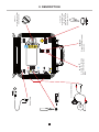
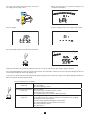
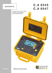
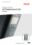
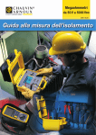
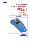
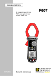
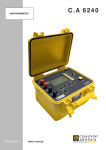
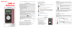
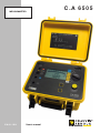
MEGOHMMETER ENGLISH User’s manual C.A 6505 Thank you for purchasing a C.A. 6505 megohmmeter. To obtain the best service from your instrument: read this user manual carefully, comply with the precautions for use. WARNING, risk of DANGER! The operator must refer to this user’s manual whenever this danger symbol appears. Equipment protected by double insulation. WARNING! Risk of electric shock. The voltage of the parts identified by this symbol may be ≥ 120 Vdc. For safety reasons, this symbol is displayed when such a voltage is generated. Earth. The CE marking indicates conformity with European directives, in particular LVD and EMC. The rubbish bin with a line through it indicates that, in the European Union, the product must undergo selective disposal in compliance with Directive WEEE 2002/96/EC. This equipment must not be treated as household waste. Definition of measurement categories: Measurement category IV corresponds to measurements taken at the source of low-voltage installations. Example: power feeders, counters and protection devices. Measurement category III corresponds to measurements on building installations. Example: distribution panel, circuit-breakers, machines or fixed industrial devices. Measurement category II corresponds to measurements taken on circuits directly connected to low-voltage installations. Example: power supply to electro-domestic devices and portable tools. PRECAUTIONS FOR USE This device is compliant with safety standard IEC 61010-2-030 and the leads are compliant with IEC 61010-031, for voltages up to 1000 V with respect to earth in category III. Failure to observe the safety instructions may result in electric shock, fire, explosion, and destruction of the instrument and of the installations. The operator and/or the responsible authority must carefully read and clearly understand the various precautions to be taken in use. Sound knowledge and a keen awareness of electrical hazards are essential when using this instrument. If you use this instrument other than as specified, the protection it provides may be compromised, thereby endangering you. Do not use the instrument on networks of which the voltage or category exceeds those mentioned. Do not use the instrument if it seems to be damaged, incomplete, or poorly closed. Before each use, check the condition of the insulation on the leads, housing, and accessories. Any item of which the insulation is deteriorated (even partially) must be set aside for repair or scrapping. Use personal protection equipment systematically. Use only the accessories delivered with the instrument. Respect the value and type of the fuse to avoid damaging the instrument and cancelling the warranty. Set the switch to OFF when the instrument is not in use. The battery must be charged before metrological tests. All troubleshooting and metrological checks must be performed by competent and accredited personnel. 2 CONTENTS 1. FIRST-TIME USE....................................................................................................................................................................... 4 1.1. Unpacking....................................................................................................................................................................... 4 1.2. Battery charge................................................................................................................................................................. 4 2. DESCRIPTION........................................................................................................................................................................... 5 2.1. Functions of the instrument............................................................................................................................................. 6 2.2. Switch.............................................................................................................................................................................. 6 2.3. Keys and button.............................................................................................................................................................. 6 2.4. Display............................................................................................................................................................................. 7 3. MEASUREMENT FUNCTIONS................................................................................................................................................. 8 3.1. Voltage measurement...................................................................................................................................................... 8 3.2. Insulation measurement ................................................................................................................................................. 8 3.3. Measurement of the PI.................................................................................................................................................. 10 3.4. Adjustment of the variable test voltage......................................................................................................................... 11 3.5. Adjustment of the maximum test voltage...................................................................................................................... 11 3.6. Error messages............................................................................................................................................................. 12 4. COMPLEMENTARY FUNCTIONS.......................................................................................................................................... 13 4.1. Adjustments of the PI.................................................................................................................................................... 13 4.2. Serial number................................................................................................................................................................ 13 4.3. Internal software version............................................................................................................................................... 14 5. SPECIFICATIONS.................................................................................................................................................................... 15 5.1. Reference conditions..................................................................................................................................................... 15 5.2. Characteristics per function ......................................................................................................................................... 15 5.3. Power supply................................................................................................................................................................. 18 5.4. Construction specifications........................................................................................................................................... 18 5.5. Environmental parameters............................................................................................................................................ 18 5.6. Compliance with international standards...................................................................................................................... 19 5.7. Variations in operating range......................................................................................................................................... 19 6. MAINTENANCE....................................................................................................................................................................... 20 6.1. Servicing........................................................................................................................................................................ 20 6.2. Calibration check........................................................................................................................................................... 20 6.3. Repair............................................................................................................................................................................ 20 7. WARRANTY............................................................................................................................................................................ 21 8. GLOSSARY.............................................................................................................................................................................. 22 9. TO ORDER............................................................................................................................................................................... 23 9.1. Accessories................................................................................................................................................................... 23 9.2. Replacement parts........................................................................................................................................................ 23 3 1. FIRST-TIME USE 1.1. UNPACKING ➀ ➃ ➆ ➅ ➂ ➄ ➀ ➁ ➂ ➃ ➄ ➅ ➆ ➁ One carrying bag. Two 2 m safety leads with a high-voltage plug at each end (one red and one blue). One 2 m guarded safety lead with a high-voltage plug at one end and a high-voltage plug with rear pick-up jack at the other end (black). One 0.35 m guarded safety lead with a high-voltage plug at one end and a high-voltage plug with rear pick-up jack at the other end (blue). Three alligator clips (red, blue, and black). One 1.80 m line power cord. One user manuals on CD-ROM (1 file per language). 1.2. BATTERY CHARGE Before first using, start by fully charging the battery. Charging must be done at between 20 and 30°C. > 110 Vac < 240 Vac 50 / 60 Hz Connect the instrument to line power using the power cord. Charging takes between 6 and 10 hours, depending on the battery’s initial charge. 4 5 M Connection terminals Protecting fuse Battery charge FF 0.1A 380V-10kA 5x20mm > 2500V and to modify the flashing values in the SET positions (blue). 1000V CAT III ( 2500V ) 110-230V 50/60 Hz 20 VA max OFF MEGOHMMETER C.A 6505 START/STOP (>2s:DAR-PI ) ( For calibration ) only DISPLAY Display of all measurement parameters. DISPLAY 500V 2T Ω 1000V 4T Ω 2500V 10T Ω 5000V 10T Ω Var 50-5000V SET Var SET V.LOCK START/STOP To start the measurements and commence the measurement of the DAR and of the PI. Choice of measurement voltage or SET positions. 2. DESCRIPTION 2.1. FUNCTIONS OF THE INSTRUMENT The C.A 6505 megohmmeter is a portable instrument housed in a rugged field case with lid and operates on either battery or line power. It makes voltage, insulation, and capacitance measurements. This instrument contributes to the safety of electrical installations and equipment. It has many advantages, for example: automatic voltage measurement, automatic detection of the presence of an external AC or DC voltage on the terminals, before or during the measurements, that disables or stops the measurements, the simplicity of the user interface, calculation of the PI and of the DAR, fuse protection of the instrument, with detection of a defective fuse, operator safety thanks to the automatic discharging of the device tested, automatic power-down of the instrument to extend battery life, an indication of the battery charge condition, a large backlit LCD display unit with many announciators for very easy reading. 2.2. SWITCH The rotary switch has 8 positions: OFF instrument powered down. 500 V - 2 TΩ insulation measurement at 500 V, up to 2 TΩ. 1000 V - 4 TΩ insulation measurement at 1000 V, up to 4 TΩ. 2500 V - 10 TΩ insulation measurement at 2500 V, up to 10 TΩ. 5000 V - 10 TΩ insulation measurement at 5000 V, up to 10 TΩ. Var. 50 - 5000 V insulation measurement with variable test voltage. SET Var sets the user definable test voltage for the Var. 50 - 5000 V position. SET V.LOCK sets the user definable maximum test voltage output irrespective of the insulation measurement positions. 2.3. KEYS AND BUTTON START/STOP DISPLAY This button is pressed to start then stop the measurement. A long press starts the measurement of the DAR and of the PI. Before, during or after the measurement, pressing this key displays the various measurement parameters. This function is available only in the SET positions of the switch. It increments the parameter displayed in flashing mode. This function is available only in the SET positions of the switch. It decrements the parameter displayed in flashing mode. Keeping the and keys pressed accelerates the rate at which the parameters change. 6 2.4. DISPLAY 0.1M 1M 10M 100M 1G 10G 100G 1T min sec DC VAC PI DAR µA nA µF 2.4.1. DIGITAL DISPLAY The main digital display indicates the values for insulation measurement: resistance, DAR PI, DD or capacity. The small digital display unit indicates the test voltage applied by the instrument or the voltage measured on the object tested. During the insulation measurement, it indicates the elapsed time or the test voltage. 2.4.2. BARGRAPH The bargraph is active during the insulation measurement (0.1 MΩ to 1 TΩ). It also serves to indicate the condition of the battery. 2.4.3. SYMBOLS DAR PI Indicates the result of these measurements. Indicates that the voltage generated is dangerous, U > 120 VDC. Indicates the presence of an external voltage. Indicates the duration of the measurement, or the time remaining in the case of a PI measurement. Indicates that the battery is low and must be recharged (see § 1.2). Indicates a flashing. 7 3. MEASUREMENT FUNCTIONS 3.1. VOLTAGE MEASUREMENT As soon as the switch is set to an insulation measurement position, the instrument automatically measures the presence of any AC/DC voltage. This voltage is measured at all times and indicated on the small display unit. The instrument automatically determines AC or DC: the AC measurement is an RMS value1. If an excessively high external voltage is present on the terminals (> 0.4 Un), pressing the START button has no effect and no measurements are made. Similarly, if an excessively high spurious voltage (> 0.4 Un) is detected during the measurement, the measurement is automatically stopped. 3.2. INSULATION MEASUREMENT Depending on the measurements to be made, there are three ways to connect the instrument. In all cases, disconnect the device to be tested from the source. Weak insulation Connect the red high-voltage lead between earth and the + terminal of the instrument. Connect the black high-voltage lead between one phase of the motor and the - terminal of the instrument. Strong insulation For a very high insulation value, connect the small blue highvoltage lead between the rear earth pick-up jack of the black lead and the G terminal of the instrument. This serves to reduce any external influence and obtain a more stable measurement. Cable Connect the red high-voltage lead between the braid and the + terminal of the instrument. Connect the black high-voltage lead between the core and the - terminal of the instrument. Connect the blue high-voltage lead between the insulation and the G terminal of the instrument. M - M - + + G G Exterior insulation The guard serves to eliminate the effect of surface leakage currents. Insulation Core + - Braid 1: RMS (Root Mean Square): root-mean-square value of the signal, determined by taking the square root of the mean value of the signal squared. 8 Once the connections have been made, choose the test voltage on the rotary switch. When powered up, the instrument displays the condition of the battery, V 1000V 4T Ω 1000V 4T Ω OFF then the voltage present on the object to be tested. the test voltage, V V Press the START/STOP key to start the measurement. 0.1M 1M 10M 100M 1G 10G 100G 1T V START/STOP During measurements the instrument will beep every 10 seconds to alert the user that a high voltage is present. Press the START/STOP key again to stop the measurement. The instrument continues to measure external voltages but the test result remains displayed on the main display unit. To ensure your safety, the instrument will automatically discharge the circuit under test, allow for the voltage displayed to fall back below 25 V before disconnecting the leads. Press the DISPLAY key to display: DISPLAY Before the measurement (2 presses) the voltage present on the device to be tested, the test voltage, the surface leakage current. During the measurement (2 presses) the test voltage, the instantaneous insulation resistance value, the duration of the measurement, the current flowing in the resistance being measured. After the measurement (5 presses) the voltage present on the device tested, the insulation resistance value just before the measurement was stopped, the duration of the measurement, the test voltage generated during the measurement, the current that flowed in the resistance measured, the surface leakage current, the capacitance. 9 3.3. MEASUREMENT OF THE PI Set the switch to one of the insulation measurement positions. 1000V 4T Ω Start the measurement by a long press on the START/ STOP key. The long press is acknowledged by an audible beep. > 2s 1000V 4T Ω OFF START/STOP The measurement starts for a duration of 10 min. A countdown displays the time remaining. 0.1M 1M 10M 100M 1G 10G 100G And the measurement stops automatically. 1T min sec V PI Press the DISPLAY key to display: DISPLAY Before the measurement (2 presses) the voltage present on the device to be tested, the test voltage, the leakage current present. During the measurement (4 presses) the measurement time remaining, the instantaneous insulation resistance value, the test voltage, the current flowing in the resistance being measured, the value of the PI (available at the end of 10 mn), the value of the DAR (available at the end of one minute). After the measurement (6 presses) the test voltage generated during the measurement, the PI, the DAR, the duration of the measurement, the insulation resistance value just before the measurement was stopped, the current that flowed in the resistance measured, the voltage present on the device being tested, the capacitance, the surface leakage current. The values of PI and DAR are calculated as follows: PI = R 10 min / R 1 min (2 values to be recorded during a measurement lasting 10 mn) 1 DAR = R 1 min / R 30 s (2 values to be recorded during a measurement lasting 1 mn) They are especially useful for monitoring the ageing of the insulation of revolving machines or of very long cables. On items of this type, the measurement is initially perturbed by spurious currents (capacitive charging current, dielectric absorption current) that gradually cancel out. To measure the leakage current representative of the insulation accurately, it is therefore necessary to make measurements of long duration. 2 : For the calculation of the PI, the times of 1 and 10 minutes can be modified by the user, if required, for a particular application. See § 4.1. 10 The quality of the insulation is a function of the results found. DAR PI Condition of the insulation < 1.25 <1 Inadequate or even dangerous <2 < 1.6 <4 Good > 1.6 >4 Excellent 3.4. ADJUSTMENT OF THE VARIABLE TEST VOLTAGE This function makes it possible to use test voltages other than the 4 available. Set the switch to SET Var. SET Var The test voltage flashes. SET Var V OFF Then set the switch to Var 50 - 5000 V to make the measurement. Change it using the and keys. Var 50-5000V Var 50-5000V V OFF This value is retained in a non-volatile memory. 3.5. ADJUSTMENT OF THE MAXIMUM TEST VOLTAGE The user can set a maximum generated voltage to prevent any accidental over-voltage tests being conducted in error. Set the switch to SET V.LOCK. SET V.LOCK The maximum test voltage flashes. SET V.LOCK V OFF Change it using the and keys. You can then turn the switch to an insulation measurement setting and make measurements. 11 The maximum test voltage value is retained in a non-volatile memory. It will be displayed for a few seconds on selection of an affected range. For example, if the maximum voltage is 750 V, it will be applied and displayed on all settings of the switch from 1000 V up. 3.6. ERROR MESSAGES 0.1M 1M 10M 100M 1G 10G 100G 1T The insulation resistance is too low. V 0.1M 1M 10M 100M 1G 10G Check your connections, the + and - terminals of the instrument may be short-circuited. 100G 1T The insulation resistance is outside the measurement range. V VAC Check your connections; one of the terminals of the instrument may be disconnected, or else the value measured is in fact > 4 TΩ. The spurious voltage present on the terminals is greater than 25 VAC or 35 Vpeak. The instrument alerts you but does not prevent making the measurements. The spurious voltage present on the terminals is too high for a measurement to be made: VAC peak spurious V > 0.4 Un The test voltage, Un, is indicated by the setting of the switch. Eliminate the spurious voltage and restart the measurement. Indicates that the protective fuse of the G terminal is defective. Replace the fuse as indicated in § 6.1.2. 12 4. COMPLEMENTARY FUNCTIONS 4.1. ADJUSTMENTS OF THE PI It is possible to modify the PI times to meet specific needs. This function is not readily accessible because it is not often used. Reminder: PI = R 10 min / R 1 min The first PI time is 1 mn. It can be set to values from 30 s to 30 mn in 30 s steps. Keep the DISPLAY key pressed and turn the switch to the SET Var position. SET Var You can change the first PI time (PI_1) using the and keys. SET Var min sec + DISPLAY OFF To save changes simply, turn the switch. The second PI time (PI_2) is 10 min. It can be set to values from PI_1 up to 59 mn in 1 mn steps. Keep the DISPLAY key pressed and turn the switch to the SET V.LOCK position. SET V.LOCK You can modify the second PI time using the and keys. SET V.LOCK min sec + DISPLAY OFF To save changes simply, turn the switch. 4.2. SERIAL NUMBER To view the serial number of the instrument, keep the DISPLAY key pressed and turn the switch to the 500 V position. DISPLAY + 500V 2T Ω 500V 2T Ω OFF 13 4.3. INTERNAL SOFTWARE VERSION To view the internal software version of the instrument, keep the DISPLAY key pressed and turn the switch to the 1000 V position. DISPLAY + 1000V 4T Ω 1000V 4T Ω OFF 14 5. SPECIFICATIONS 5.1. REFERENCE CONDITIONS Influence quantities Reference values Temperature 23 ± 3°C Relative humidity 45 to 55% RH Supply voltage 9 to 12 V Frequency range DC and 15.3...65 Hz Capacity in parallel on resistor 0 µF Electrical field nil Magnetic field < 40 A/m 5.2. CHARACTERISTICS PER FUNCTION 5.2.1. VOLTAGE Characteristics Measurement range Frequency range 1.0 - 99.9 V 100 - 999 V DC and 15 Hz - 500 Hz 3 Resolution 0.1 V Accuracy 1% ± 5 pt Input impedance 1000 - 2500 V 1000 - 5100 V 15 Hz - 500 Hz DC 2V 2V 1V 1% ± 1 pt 750 kΩ at 3 MΩ depending on measured voltage 3: Over 500 Hz, the small display indicates “- - - -” and the main display gives only an assessment of the peak value of the measured voltage. 5.2.2. CURRENT Current measurement before the insulation measurement: Measurement range 0.000 0.250 nA 0.250 9.999 nA 10.00 99.99 nA 100.0 999.9 nA 1000 9.999 µA 10.00 99.99 µA 100.0 999.9 µA 10 pA 100 pA 1 nA 10 nA 100 nA Resolution 1 pA 1 pA Accuracy 15% ± 10 pt 10% 5% 1000 3000 µA 1 µA 10% Current measurement during the insulation measurement: Measurement range 0.000 0.250 nA 0.250 9.999 nA 10.00 99.99 nA 100.0 999.9 nA 1.000 9.999 µA 10.00 99.99 µA 100.0 999.9 µA 1000 3000 µA Resolution 1 pA 1 pA 10 pA 100 pA 1 nA 10 nA 100 nA 1 µA Accuracy 15% ± 10 pt 10% 5% 3% The 0.250 nA and 3000 µA ranges are not used for the insulation resistance calculations. 5.2.3. INSULATION RESISTANCE Method: Voltage-current measurement as per IEC 61557-2 (Ed. 02/97) Nominal output voltage: 500, 1000, 2500, 5000 Vdc or adjustable from 40 V to 5100 V No-load voltage: 510, 1020, 2550 and 5100 V ± 2% and Un ± 2% in variable mode Variable voltage adjustment step: 10 V from 40 V to 1000 V 100 V from 1000 V to 5100 V Nominal current: ≥ 1 mAdc at the nominal voltage Short-circuit current: 1.6 mA ± 5% (3.1 mA max. when the measurement is started) Maximum acceptable spurious voltage during the measurement: Upeak = 0.4 Un 15 5% Accuracy Test voltage 500 V - 1000 V - 2500 V - 5000 V Specified measurement range 10 - 999 kΩ 1.000 - 3.999 MΩ 4.00 - 39.99 MΩ 40.0 - 399.9 MΩ 0.400 - 3.999 GΩ 1 kΩ 10 kΩ 100 kΩ 1 MΩ Resolution Accuracy ±5% + 3 pt Test voltage Specified measurement range Resolution 500 V - 1000 V - 2500 V - 5000 V 4.00 - 39.99 GΩ 40.0 - 399.9 GΩ 10 MΩ 100 MΩ Accuracy 0.400 - 1.999 TΩ 1000 V - 2500 V 5000 V 2500 V 5000 V 2.000 - 3.999 TΩ 4.00 - 9.99 TΩ 1 GΩ ± 5% + 3 pt 10 GΩ ±1 5% + 10 pt Accuracy in variable mode Rmeasured = Un / 250 pA Test voltage 40 - 160 V 170 - 510 V 520 - 1500 V 1600 - 5100 V Rmeasured min 10 kΩ 10 kΩ 10 kΩ 10 kΩ Rmeasured max 160.0 GΩ - 640.0 GΩ 640.0 GΩ - 2.040 TΩ 2.080 TΩ - 6.000 TΩ 6.400 TΩ - 10.00 TΩ To obtain the accuracy in variable voltage mode, calculate from the accuracies of the fixed voltages above. Measurement of DC voltage during insulation test Specified measurement range Resolution 40.0 - 99.9 V 100 - 1500 V 1501 - 5100 V 0.1 V 1V 2V Accuracy 1% ± 1 pt Measurement of the test voltage after a capacitive insulation measurement Specified measurement range 25 - 5000 V Resolution 0.2% Un or 1 pt Accuracy 5% ± 3 pt Calculation of terms DAR and PI Specified range 0.02 - 50.00 Resolution 0.01 Accuracy 5% ± 1 pt 16 Typical change curve for test voltages according to load Range 500 V V 600 500 400 300 200 100 MΩ 0 0,01 0,1 1 Range 1000 V V 1200 1000 800 600 400 200 0 0,01 0,1 1 10 MΩ Range 2500 V V 3000 2500 2000 1500 1000 500 0 0,01 0,1 1 10 1 10 MΩ Range 5000 V V 6000 5000 4000 3000 2000 1000 0 0,01 0,1 17 MΩ 5.2.4. CAPACITANCE This measurement is made at the end of each insulation measurement, while the circuit is being discharged. Specified measurement range 0.001 - 9.999 µF 10.00 - 49.99 µF Resolution 1 nF 10 nF Accuracy 10% ± 1 pt 10% 5.3. POWER SUPPLY The equipment power supply is obtained from: Rechargeable NiMh batteries - 8 x 1.2 V / 3.5 Ah Line voltage: 85 to 256 V / 50-60 Hz Consumption For insulation measurements at 5000 V and 1 mA: 11 W For voltage measurements: 0.9 W On standby: 0.01 W Minimum operating time (per IEC 61557) Test voltage 500 V 1000 V 2500 V 5000 V Nominal load 500 kΩ 1 MΩ 2.5 MΩ 5 MΩ 6500 5500 4000 1500 Number of measurements (with 25 s pause between each measurement) In voltage measurement mode, the battery life is 35 hours. Recharge time Charging must be done between 20 and 30°C. 6 hours to recover 100% capacity (10 hours if the battery is completely run down). 0.5 hours to recover 10% capacity (charge life: 2 days approximately) It is essential to charge the battery before calibration tests. Note: It is possible to recharge the batteries while performing insulation measurements provided that the values measured are higher than 20 MΩ. In this case, the recharging time is higher than 6 hours. Otherwise, the battery is discharged faster than it is charged. 5.4. CONSTRUCTION SPECIFICATIONS Overall dimensions of the unit (L x l x h): 270 x 250 x 180 mm Weight: approximately 4.3 kg 5.5. ENVIRONMENTAL PARAMETERS Range of use -10°C to 40°C, during battery recharging -10°C to 55°C, during measurement 20% to 80% RH Storage -40 at 70°C, from 10% to 90% RH Altitude: < 2000 m Use indoors or outdoors. 18 Diagram of climatic conditions: % RH 100 90 80 70 60 3 50 2 1 40 30 20 10 0 -50 -40 -30 -20 -10 0 °C 10 20 30 40 50 60 70 80 90 1: Reference range 2: Operating range 3: Storage range (without battery) 5.6. COMPLIANCE WITH INTERNATIONAL STANDARDS Electrical safety as per:IEC 61010-1 and IEC 61557 Double insulation Pollution level: 2 Measurement category: III Max. voltage relative to earth: 1000 V (2500 V in measurement category I) 5.6.1. ELECTROMAGNETIC COMPATIBILITY Emissions and immunity in an industrial setting compliant with EN 61326-1. 5.6.2. MECHANICAL PROTECTION IP 53 per IEC 60529 IK 04 per IEC 50102 5.7. VARIATIONS IN OPERATING RANGE Influential quantity Battery voltage Temperature Humidity Frequency AC voltage superimposed on the Test voltage Influence Quantity influenced 4 Typical Maximum V MΩ < 1 pt < 1 pt 2 pt 3 pt -10°C +55°C V MΩ 0.15% /10°C 0.20% /10°C 0.3% /10°C +1 pt 1% /10°C + 2 pt 20% - 80% HR V MΩ (10 kΩ to 40 GΩ) MΩ (40 GΩ to 10 TΩ) 0.2% 0.2% 0.3% 1% +2 pt 1% +5 pt 15% +5 pt 15 - 500 Hz V 3% 0.5% +1 pt 0% Un - 20% Un MΩ 0.1% / % Un 0.5% / % Un +5 pt Range of influence 9 V - 12 V 4: The terms DAR and PI and the capacitance and current leak measurements are included in the quantity “MΩ”. 19 6. MAINTENANCE Except for the fuse, the instrument contains no parts that can be replaced by personnel who have not been specially trained and accredited. Any unauthorized repair or replacement of a part by an “equivalent” may gravely impair safety. 6.1. SERVICING 6.1.1. BATTERY RECHARGE If the symbol is displayed, the battery must be recharged. Connect the instrument to line power using the mains lead; it starts charging automatically and the symbol flashes: bAt on the small display unit and chrG on the main display unit means fast charging in progress. bAt on the small display unit and chrG flashing on the main display unit means that slow charging is in progress bAt on the small display unit and FULL on the main display unit means that charging is over. The battery must be replaced by Manumesure or by a repairer approved by CHAUVIN ARNOUX. 6.1.2. REPLACEMENT OF THE FUSE If FUSE -G- appears on the display. Ensure the instrument is disconnected from any source (both test leads and mains lead) the instrument is switched off and replace the fuse located on the front panel. For your safety, replace a defective fuse with only a fuse having strictly identical characteristics: Exact type of fuse (entered on the label on the front panel): FF - 0.1 A - 380 V - 5 x 20 mm - 10 kA. Note: This fuse is in series with a 0.5 A / 3 kV internal fuse active only in case of major fault in the unit. If after changing the fuse on the front panel, the display still indicates FUSE - G -, the unit must be returned for servicing (see § 6.3) 6.1.3. CLEANING Disconnect the unit completely and turn the rotary switch to OFF. Use a soft cloth, dampened with soapy water. Rinse with a damp cloth and dry rapidly with a dry cloth or forced air. Do not use alcohol, solvents, or hydrocarbons. 6.1.4. STORAGE If the instrument has been left unused for an extended period (more than two months), fully charge the battery before using. 6.2. CALIBRATION CHECK Like all measuring or testing devices, regular instrument verification is necessary. This instrument should be checked at least once a year. For checks and calibrations, contact one of our accredited metrology laboratories (information and contact details available on request), at our Chauvin Arnoux subsidiary or the branch in your country. 6.3. REPAIR For all repairs before or after expiry of warranty, please return the device to your distributor. 20 7. WARRANTY Except as otherwise stated, our warranty is valid for twelve months starting from the date on which the equipment was sold. Extract from our General Conditions of Sale provided on request. The warranty does not apply in the following cases: inappropriate use of the equipment or use with incompatible equipment; modifications made to the equipment without the explicit permission of the manufacturer’s technical staff; work done on the device by a person not approved by the manufacturer; adaptation to a particular application not anticipated in the definition of the equipment or not indicated in the user manual; damage caused by shocks, falls, or floods. 21 8. GLOSSARY This glossary lists the terms and abbreviations used in this document and on the digital display unit of the instrument. bAt Battery charge condition DAR Dielectric Absorption Ratio. DAR = R 1 min / R 30 s LIM Maximum test voltage that will be applied during the measurement PI Polarisation Index. PI = R 10 min / R 1 min Pdn Power Down (standby) tESt Test voltage that will be applied during the measurement Un Nominal test voltage 22 9. TO ORDER C.A 6505 Megohmmeter ........................................................................................................................................... P01139704 Delivered with a carrying bag containing: Two 2 m safety leads with a HV plug at each end (one red and one blue). One 2 m guarded safety lead with a HV plug at one end and a HV plug with a rear pick-up jack at the other end (black). One 0.35 m guarded safety lead with a HV plug at one end and a HV plug with a rear pick-up jack at the other end (blue). Three alligator clips (red, blue and black) 1.80-m mains power lead One user manuals on CD-ROM (1 file per language). 9.1. ACCESSORIES 3 HV cable (red + blue + guarded black) 3 m long.......................................................................................................P01295220 Blue HV lead with alligator clip, 8 m long.....................................................................................................................P01295214 Red HV lead with alligator clip, 8 m long.....................................................................................................................P01295215 Black HV lead with alligator clip and earth pick-up jack, 8 m long..............................................................................P01295216 Blue HV lead with alligator clip, 15 m long...................................................................................................................P01295217 Red HV lead with alligator clip, 15 m long...................................................................................................................P01295218 Black HV lead with alligator clip and earth pick-up jack, 15 m long............................................................................P01295219 9.2. REPLACEMENT PARTS Set of 2 HV cables with safety connectors ∅ 4 mm (red/ guarded black) 3 m............................................................P01295231 HV cable with safety connector ∅ 4 mm (blue) 3 m + alligator clip (blue)...................................................................P01295232 Set of 2 alligator clips (red/black).................................................................................................................................P01102052Z Set of 2 test prods (red/black)......................................................................................................................................P01102051Z HV cable with safety connector ∅ 4 mm (blue) 3 m + alligator clip (blue)...................................................................P01295232 0.35 m rear pick up lead...............................................................................................................................................P01295221 Standard carrying bag..................................................................................................................................................P01298066 Fuse FF 0.1 A - 380 V - 5 x 20 mm - 10 kA (batch of 10).............................................................................................P03297514 Battery 9.6 V - 3.5 AH - NiMh......................................................................................................................................P01296021 Mains power supply cable 2P......................................................................................................................................P01295174 23 02 - 2015 Code 692056B02 - Ed. 2 DEUTSCHLAND - Chauvin Arnoux GmbH Ohmstraße1 - 77694 Kehl / Rhein Tel: (07851) 99 26-0 - Fax: (07851) 99 26-60 SCHWEIZ - Chauvin Arnoux AG Moosacherstrasse 15 - 8804 AU / ZH Tel: 044 727 75 55 - Fax: 044 727 75 56 UNITED KINGDOM - Chauvin Arnoux Ltd Unit 1 Nelson Ct - Flagship Sq - Shaw Cross Business Pk Dewsbury, West Yorkshire - WF12 7TH Tel: 01924 460 494 - Fax: 01924 455 328 中国 – 上海浦江埃纳迪斯仪表有限公司 上海市虹口区祥德路381号3号楼3楼 Tel: +86 21 65 21 51 96 - Fax: +86 21 65 21 61 07 ITALIA - Amra SpA Via Sant’Ambrogio, 23/25 - 20846 Macherio (MB) Tel: 039 245 75 45 - Fax: 039 481 561 ESPAÑA - Chauvin Arnoux Ibérica S.A. C/ Roger de Flor, 293 - 1a Planta - 08025 Barcelona Tel: 90 220 22 26 - Fax: 93 459 14 43 ÖSTERREICH - Chauvin Arnoux Ges.m.b.H Slamastrasse 29/2/4 - 1230 Wien Tel: 01 61 61 9 61-0 - Fax: 01 61 61 9 61-61 MIDDLE EAST - Chauvin Arnoux Middle East P.O. BOX 60-154 - 1241 2020 JAL EL DIB (Beirut) - LEBANON Tel: (01) 890 425 - Fax: (01) 890 424 SCANDINAVIA - CA Mätsystem AB Sjöflygvägen 35 - SE 18304 TÄBY Tel: +46 8 50 52 68 00 - Fax: +46 8 50 52 68 10 USA - Chauvin Arnoux Inc - d.b.a AEMC Instruments 200 Foxborough Blvd. - Foxborough - MA 02035 Tel: (508) 698-2115 - Fax: (508) 698-2118 http://www.chauvin-arnoux.com 190, rue Championnet - 75876 PARIS Cedex 18 - FRANCE Tél. : +33 1 44 85 44 85 - Fax : +33 1 46 27 73 89 - [email protected] Export : Tél. : +33 1 44 85 44 38 - Fax : +33 1 46 27 95 59 - [email protected]