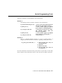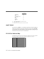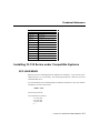
1
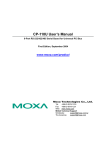
Industio CI-132 Series User’s Manual Industrial 2 Port RS-422/RS-485 Serial Board Feb. 1999 (1st Edition) The content of this manual is also available at Moxa Web Site. Moxa Technologies Co., Ltd. Tel: +866-2-8665-6373 Fax: +886-2-8665-6372 www.moxa.com [email protected] Industio CI-132 Series User’s Manual The product described in this manual is furnished under a license agreement and may be used only in accordance with the terms of the agreements. Copyright Notice Copyright 1999 Moxa Technologies Co., Ltd. All rights reserved. Reproduction in any form without permission is prohibited. Trademarks MOXA is a registered trademark of Moxa Technologies Co., Ltd. All other trademarks or registered marks in this manual belong to their respective manufacturers. Disclaimer Information in this document is subject to change without notice and does not represent a commitment on the part of Moxa. Moxa provides this document “as is”, without warranty of any kind, either expressed or implied, including, but not limited to, the particular purpose. Moxa may make improvements and/or changes in this manual or in the product(s) and/or the program(s) described in this manual at any time. Information provided in this manual is intended to be accurate and reliable. However, Moxa Technologies assumes no responsibility for its use, or for any infringements of rights of the fourth parties which may result from its use. This product could include technical or typographical errors. Changes are periodically made to the information herein; these changes may be incorporated in new editions of the publication. MOXA Internet Services Customer’s satisfaction is always our number one concern. To ensure that customers get the full benefit of our services, Moxa Internet Services have been built for technical support, product inquiry, new driver update, user’s manual update, etc. The followings are the services we provide. E-mail for technical support address: [email protected] FTP site for free driver update address: ftp.moxa.com or ftp.moxa.com.tw user ID: ftp password: your_email_address World Wide Web (WWW) Site for product info address: www.moxa.com or www.moxa.com.tw About this Manual This manual is composed of six chapters and one appendix. This manual is written for installers, system administrators and software programmers. If you are a first-time installer and system administrator, we recommend you to go through the whole manual except chapter 4. If you are a software programmer, you may refer to chapter 4, “Serial Programming Tools”. If you need cable wiring information, please see the “Connection Cable and Cable Wiring” chapter. If you encounter any problem during the installation, please refer to the “Troubleshooting” chapter. Chapter 1 Introduction Overview and features of the Industio CI-132 Series boards, list of items and overall installation guide. Chapter 2 Hardware Installation Hardware installation for the Industio CI-132 Series boards and connection cable. Hardware configuration utility, Io-irq.exe, is detailed. Chapter 3 Software Installation Software installation, configuration, driver loading/unloading, driver update and removal for various operating systems: Windows NT, Windows 95/98 and DOS. Chapter 4 Serial Programming Tools Short description of the programming tools, PComm, under Windows NT and Windows 95/98 and API-232 under DOS. Also RS-485 programming issue is covered. Chapter 5 Connection Cable and Cable Wiring Description of the RS-422 and RS-485 cable wiring for the connection cable. Chapter 6 Troubleshooting Common problems and possible answers for the Industio CI-132 Series boards. Appendix Specification details, UART, Installation under compatible systems and I/O port address map. Table of Contents Introduction ..................................................................... 1-1 Overview ................................ ................................ ................................ ........................... 1-1 Features ................................ ................................ ................................ ............................ 1-3 Check List................................ ................................ ................................ .......................... 1-4 Installation Guide................................ ................................ ................................ ............... 1-5 Hardware Installation ...................................................... 2-1 First Thing to Do: Interface Settings................................ ................................ ................... 2-2 Quick Hardware Installation................................ ................................ ............................... 2-3 How to Do Quick Hardware Installation ....................................................................................2-3 Hardware Installation with IO-IRQ Utility................................ ................................ ............2-4 IO-IRQ Utility and Hardware Configuration..............................................................................2-5 Software Installation ....................................................... 3-1 Windows NT................................ ................................ ................................ ...................... 3-1 Installing Driver ........................................................................................................................3-2 Configuring Board and Port ......................................................................................................3-7 Updating Driver ........................................................................................................................3-9 Removing Driver........................................................................................................................3-9 Windows 95/98................................ ................................ ................................ ................ 3-10 Installing Driver ...................................................................................................................... 3-10 Configuring Board and Port ....................................................................................................3-14 Updating Driver ...................................................................................................................... 3-15 Removing Driver...................................................................................................................... 3-16 DOS ................................ ................................ ................................ ................................ 3-17 Installing Driver ...................................................................................................................... 3-17 Driver Setup ............................................................................................................................ 3-18 Loading Driver ........................................................................................................................ 3-22 Unloading Driver..................................................................................................................... 3-23 Serial Programming Tools ................................................ 4-1 Windows NT and Windows 95/98................................ ................................ ...................... 4-1 PComm Installation .....................................................................................................................4-1 PComm Programming Library.....................................................................................................4-2 Utilities......................................................................................................................................4-2 DOS ................................ ................................ ................................ ................................ ..4-5 Installing API-232 .....................................................................................................................4-5 DOS API-232 Library ................................................................................................................4-5 Utilities......................................................................................................................................4-5 RS-485 Programming ................................ ................................ ................................ ........4-8 Automatic Data Direction Control Mode (Recommended)..........................................................4-8 By RTS Mode (For back-compatibility) ......................................................................................4-8 Connection Cable and Cable Wiring.................................. 5-1 RS-422 Cable Wiring................................ ................................ ................................ .........5-1 RS-485 Cable Wiring................................ ................................ ................................ .........5-3 Impedance Matching and Termination Resistors................................ ................................ 5-4 Troubleshooting ............................................................... 6-1 General Troubleshooting................................ ................................ ................................ ....6-1 Windows NT................................ ................................ ................................ ...................... 6-4 Windows 95/98................................ ................................ ................................ .................. 6-5 DOS ................................ ................................ ................................ ................................ ..6-6 Technical Reference ........................................................A-1 Specifications ................................ ................................ ................................ ................... A-1 UART TI550C................................ ................................ ................................ ................... A-2 PC I/O Port Address Map................................ ................................ ................................ .. A-2 Installing CI-132 Series under Compatible Systems................................ .......................... A-3 SCO UNIX/XENIX .................................................................................................................... A-3 1 1 Introduction Overview Industio - The Industrial Multiport Async Solution The term Industio stands for smart multiport serial I/O solution for industrial applications. The Industio CI-132 Series boards, including CI-132, CI-132I and CI-132IS, are designed for 16-bit ISA/EISA bus. They offer 2 independent RS422/RS-485 serial ports for connecting data acquisition equipment and many other serial devices to the PC and its compatible systems. It offers reliable communication link over a longer distance (4000ft). It is best suitable for industrial environment. Connections with point-to-point full-duplex or multidrop half-duplex are available to meet user’s needs. Automatic Data Direction Control for RS-485 With a well-designed and fine-tuned device driver, the Industio CI-132 boards make full use of the 32 byte Tx/Rx FIFO and on-chip H/W flow control, so that they can transfer data without loss even at high speed such as 921.6 Kbps. They offer a reliable and high performance solution for serial multiport communications. Termination Resistors Ready for RS-422/RS-485 Termination Resistors are already installed on the Industio CI-132 boards and no more headaches for finding proper resistors and connecting them for impedance matching problem. More details are in chapter, “Connection Cable and Cable Wiring”. Surge/Isolation Protection Industio CI-132 Series User’s Manual 1-1 To prevent the boards from damage caused by lighting or high potential voltage, TVSS (Transient Voltage Surge Suppressor) technology is introduced in some models to protect the board. This is critical to harsh environment such as factory. ASIC Design, Compact Size The CI-132 Series is equipped with MOXA customer-designed ASIC chip, which replaces lots of conventional IC and hence reduces the board to half-size, increase the operation performance, and lower the failure rate of the board. Full range of I/O addresses and IRQs are available. In addition, with on-board EEPROM for storing the configuration data, the family is designed without jumper or switch. These features make each port on the board truly independent to any other port and thus compatible with most existing non-intelligent boards. Because the family is so flexible in hardware configuration, it is compatible virtually with all kinds of other manufacturer's non-intelligent multiport boards using 16550 UART. CAP Jumper Interface Switch Data Mode Switch JP1 ON 1 Termination ResistorPort 2 Jumper Termination Resistor Port 1 Jumper ON 2 SW2 1 2 SW1 JP3 JP4 Industio CI-132 Series Board CAP Address Instead of using traditional jumper or switch for IRQ and I/O address settings, hardware configuration of each port is easily set by DOS utility, Io-irq.exe, which read and write the on-board EEPROM for configuration information through the CAP (Configuration Access Port) address. The CAP address is the only channel via which the configuration utility Io-irq.exe can access the board, which is identical to the first port's base I/O address. The jumper, JP1, is designed in case of that users forget the CAP address. Normally JP1 is left open. When JP1 is short, the CAP address is forced to a fixed I/O address, 0xA700. While doing quick hardware installation, JP1 is required to be shorted, 1-2 Industio CI-132 Series User’s Manual Introduction detailed in chapter, “Hardware Installation”. Quick Installation To ease the hardware configuration, users who install only one Industio CI-132 Series board under Windows NT and 95/98 are recommended to adopt quick installation described in chapter 2, “Hardware Installation”. Operating System Support The family is operational under most popular operating systems such as Windows NT, Windows 95/98, Windows 3.1, DOS, SCO UNIX/XENIX/OpenServer, Linux, QNX, FreeBSD, OS/2, etc. However, MOXA device drivers for Windows NT, Windows 95/98 and DOS are provided for better installation, configuration and performance. In this manual, chapter for MOXA Windows NT, Windows 95/98 and DOS device drivers and appendix for compatible OS are included. For those compatible systems not mentioned, please refer to system’s manual for how to install and configure the standard driver. MOXA Serial Comm Tools For application development, MOXA provides an easy-to-use serial communication library under Windows NT, Windows 95/98 (PComm) and DOS (API-232). Users can use this library to develop your own applications using Microsoft C, Turbo C, Assembly, QuickBASIC, Turbo Pascal, Clipper, Visual Basic, Visual C++, Borland Delphi, etc. Utilities, such as Data Scope, Monitor, Terminal Emulator, Diagnostics, etc., are included for debugging or monitoring the communication status or terminal emulation or even file transferring. Broad Applications The board is suitable for many industrial applications. Here are a few: l Industrial Automation l Factory Automation l Remote serial device control Features Industio CI-132 Series User’s Manual 1-3 The Industio CI-132 Series consists of members as follows, CI-132 2 RS-422/RS-485 ports, TI550C UART CI-132I 2 RS-422/RS-485 ports, isolation protection, TI550C UART CI-132IS 2 RS-422/RS-485 ports, surge and isolation protection, TI550C UART The following are the outstanding features of Industio CI-132 Series v v v v v v v v v v v v v v Support 2 independent RS-422 or RS-485 serial ports Standard COM port compatible High circuit integration with state-of-the-art ASIC design, compact half-size No I/O switch, no IRQ jumper, easily configured by software Independent I/O address, IRQ setting for each of 2 serial ports Switch for RS-422/RS-485 selection 2-wire RS-485 operation Switch for RS-485 data control¡Ð Automatic Data Direction Control Mode or By RTS Mode Jumper for Termination Resistors selection, no more headache for impedance matching Reliability ¡Ð High speed TI550C Communication Controllers with on-chip hardware flow control guarantees no data loss Support isolation or surge protection Powerful Serial Comm tools¡Ð PComm and API-232 Support popular industrial OS¡Ð Windows NT, Windows 95/98, DOS Compatible with many other OS¡Ð SCO UNIX/XENIX, QNX, Linux, FreeBSD, Windows 3.x, OS/2 CI-132 Series Windows NT Windows 95/98 DOS SCO UNIX/OpenServer SCO XENIX QNX Linux FreeBSD Windows 3.x OS/2 3 3 3 C C C C C C C 3: Driver supported by Moxa and shipped with product C : Driver supported by OS Note: Download the newest drivers from the MOXA FTP service 1-4 Industio CI-132 Series User’s Manual Introduction Check List Upon unpacking the Industio CI-132 Series package, you should find the following items: v v v Industio CI-132 Series 2 port serial board Device driver diskettes: l Windows NT and Windows 95/98¡Ñ 1 l PComm Lite¡Ñ 1 l DOS¡Ñ 1 Industio CI-132 Series User’s Manual (This manual) Installation Guide This section gives a brief summary of how to install the Industio CI-132 Series under each supported operating system. The installation is simple and involves the following stages: Configure CI-132 Series with Io-irq.exe Install the CI-132 Series board See chapter 2 Install the software from the diskette Configure the driver for the board and ports See respective O.S. Section in chapter 3 Connect the devices with the cable See chapter 5 for cable wiring Restart the system Check the driver initialization status If the system restart successfully, you may Develop your applications or Execute the desired applications See chapter 3 for board init. status checking for each O.S. See chapter 4, “Serial Programming Tools” Industio CI-132 Series User’s Manual 1-5 1-6 Industio CI-132 Series User’s Manual 2 Hardware Installation 2 The installation of the Industio CI-132 Series consists of hardware and software installation. The hardware installation is detailed in this chapter. The next chapter deals with the software installation for various operating systems. CAP Jumper Interface Switch Data Mode Switch JP1 ON 1 Termination ResistorPort 2 Jumper Termination Resistor Port 1 Jumper ON 2 SW2 1 2 SW1 JP3 JP4 Industio CI-132 Series Board The Industio CI-132 Series has the following default (factory) settings: I/O address : 0x180 (Port 1), 0x188 (Port 2) IRQ : 10 INT Vector : 0x1C0 CAP Jumper JP1: Open Interface Switch SW2: Port 1: ON (RS-485) Port 2: ON (RS-485) Data Mode Switch SW1: Port 1: ON (Automatic Data Direction Control Mode) Port 2: ON (Automatic Data Direction Control Mode) Termination Resistor Port 1 Jumper JP3: Open (not used) Termination Resistor Port 2 Jumper JP4: Open (not used) Industio CI-132 Series User’s Manual 2-1 If the default settings above are what you desired and good for the system without conflicts, you may simply install the board in the system and go directly to the next chapter, “Software Installation”. Otherwise, follow the instructions below. In addition to the normal hardware installation (detailed in the later section, “Hardware Installation with IO-IRQ Utility”), a quick hardware installation (detailed right in the next section, “Quick Hardware Installation without IO-IRQ Utility”) is provided for you to facilitate the hardware installation, only under the circumstances that: u u u Only one Industio CI-132 Series board is allowed to install in a system. Windows NT and 95/98 are the only operating systems supported. CAP Jumper JP1 is short and I/O address 0xA700 must be free. First Thing to Do: Interface Settings Before installing the board into the slot, you should set all the jumpers and switches to what you want. CAP Jumper JP1: Open Not forcing the CAP address to 0xA700. Short Force the CAP address to 0xA700. Set to this if you want to do quick hardware installation. Or forget the CAP address when you want to reconfigure the board with IOIRQ. Interface Switch SW2 for Port 1/Port 2: ON Set the port interface to RS-485. OFF Set the port interface to RS-422. Data Mode Switch SW1 for Port 1/Port 2: (Valid when SW2 is set to ON) ON Set the RS-485 port to Automatic Data Direction Control Mode. OFF Set the RS-485 port to By RTS Mode. Termination Resistor Port 1 Jumper JP3: (Valid when SW2 is set to ON) Open Not using Termination Resistor Short Using Termination Resistor Termination Resistor Port 1 Jumper JP4: (Valid when SW2 is set to ON) Open Not using Termination Resistor Short Using Termination Resistor 2-2 Industio CI-132 Series User’s Manual Hardware Installation Quick Hardware Installation To fully utilize the superior feature of flexible hardware configuration design of the Industio CI-132 Series, a quick and easy method of installation is designed, which absolutely saves you from hardware configuration effort, i.e., installation WITHOUT running configuration program: Io-irq.exe. Simply always short the jumper JP1. The software and hardware configuration will be completed at the same time while doing the software configuration, detailed in the next chapter. Of course, the method is valid only under the previously described circumstances. Besides, the speed range will be set to from 50 to 921.6K bps by default, which is called High Speed Spectrum and detailed in section "Hardware Installation with IO-IRQ Utility". How to Do Quick Hardware Installation 1. Short the jumper JP1 on the upper-left corner of the board. 2. Plug the board in PC with the desired system installed (Windows NT or 95/98), which is powered off in advance. 3. Do software (driver) installation, detailed in the next chapter. This is to specify the desired I/O address, IRQ and INT Vector in the software configuration panel, no matter what hardware settings are on the board. The software configuration program will automatically update the hardware settings. After this, users already complete the whole installation. 4. Shutdown the system (Windows NT or 95/98). 5. Do power off and then on (or Reset) the PC. (Please cold start.) 6. Restart System (Windows NT or 95/98). It is very important to keep the JP1 always short in this case. Without running the hardware configuration program, Io-irq.exe under DOS prompt, the software Industio CI-132 Series User’s Manual 2-3 configuration program will automatically update the hardware settings of the board while updating the software settings. This saves the trouble doing hardware configuration. However, remember to cold start the system every time the configuration changed. Hardware Installation with IO-IRQ Utility This section is for users in the following cases, who can not use quick hardware installation: u Install two or more Industio CI-132 Series boards in a system. u Fail to install, due to the I/O address 0xA700 is not available or has conflict in the system. u Use operating systems other than Windows NT and 95/98. Before proceeding to the software (driver) installation, detailed in the next chapter, “Software Installation”, do hardware configuration to setup the I/O and IRQ with “Io-irq.exe”, detailed in the next section. Remember to keep the hardware settings in mind for the software installation. The Industio CI-132 Series has the following default (factory) settings: I/O address : 0x180 (1st port), 0x188 (2nd port) IRQ : 10 INT Vector : 0x1C0 Because the ASIC-designed Industio CI-132 Series has no switch and no jumper for configuring manually the I/O address, IRQ, INT Vector, etc. of the boards, you must run the software utility, Io-irq.exe, in the driver diskette under DOS system to change the hardware configuration. 1. Choose a PC that has DOS system inside. 2. Power off the PC. 3. Make sure no hardware conflict and plug the board in a free 16-bit slot of the PC, one board at a time with JP1 open. 2-4 Industio CI-132 Series User’s Manual Hardware Installation + If you are installing multiple boards, insert one board at a time and configure it using the Io-irq program before inserting the next board. This is to prevent conflict between two boards with same default hardware settings. The Industio CI-132 Series has the following default (factory) settings, I/O address : 0x180 (1st port), 0x188 (2nd port) IRQ : 10 INT Vector : 0x1C0 Configuration Access Port (CAP) : 0x180 4. Power on the PC and enter into DOS system. 5. Run the utility “Io-irq.exe” contained in the driver diskette to set up I/O address, IRQ and INT vector of the board. Please refer to the next section, “IO-IRQ Utility and Hardware Configuration” for more details. Or follow the on-line help to configure the Industio CI-132 Series board. After completing the hardware configuration, the board is ready for use under operating systems, such as Windows NT and 95/98, DOS, etc. IO-IRQ Utility and Hardware Configuration Note that the CAP address, e.g. 0x180, is identical to the first port's I/O address except in one case that the JP1 jumper is installed before powering on the PC. In this case, the CAP address will be forced to 0xA700. The CAP address must be typed correctly. With the correct CAP address, the utility can find the configuration stored in the on-board EEPROM and display it on the configuration panel. The CAP address is the only channel via which the configuration utility Io-irq.exe can access the board. 1. Run the utility “Io-irq.exe” contained in the driver diskette to set up I/O address, IRQ and INT vector of the board. Industio CI-132 Series User’s Manual 2-5 2. Select “Smartio/Industio ISA Family” and press ENTER key. 2-6 Industio CI-132 Series User’s Manual Hardware Installation 3. Enter the CAP address of the Industio CI-132 Series board to be configured. 4. Configure the following parameters as necessary. Port Index Indicate the port index for each port. I/O address Enter the base I/O address for each port, either sequentially or not. Avoid to conflicting with any other devices. IRQ Enter the IRQ, 2, 3, 4, 5, 7, 10, 11, 12 or 15, for each port, independently or not. Speed This field specifies the use of normal or high speed capability. Normal speed ranges from 50 bps to 115.2 Kbps. High speed ranges from 50 bps to 921.6 Kbps. Industio CI-132 Series supported both normal and high speed spectra. Industio CI-132 Series User’s Manual 2-7 Note that, currently, port that uses MOXA Windows NT and 95/98 driver will run at the displayed speed. To be clear, when Industio CI-132 Series board is configured as High Speed Spectrum, any port driven by the Moxa-provided Windows NT and 95/98 driver will display the exact working speed. For example, the displayed speed 38.4 Kbps is equal to the working speed 38.4 Kbps. However, if the port is driven by NON Moxa-provided driver, such as standard serial driver, or Moxa drivers other than Windows NT and 95/98, such as DOS, the real working speed is equal to 8 times of the displayed speed. For example, a port, if set to Normal Speed Spectrum with 38.4 Kbps, will work at 38.4 Kbps for sure; while a port, if set to High Speed Spectrum with displayed speed 38.4 Kbps, will actually work at 307.2 Kbps (38.4 Kbps¡Ñ 8). 2-8 Industio CI-132 Series User’s Manual Hardware Installation The following is the 8 times speed mapping list for quick reference purpose, particularly for DOS driver. Normal Speed Spectrum 50 (bps) 75 110 134.5 150 300 600 1200 1800 2400 4800 7200 9600 19.2K 38.4K 57.6K 115.2K INT Vector High Speed Spectrum 400 (bps) 600 880 1076 1200 2400 4800 9600 14.4K 19.2K 38.4K 57.6K 76.8K 153.6K 307.2K 460.8K 921.6K Enter the interrupt vector I/O address for all ports. I/O address for interrupt vector is from 00000H to 0FFFFH. Interrupt vector is one byte of I/O address, in which each bit is used to indicate the occurrence of interrupt for corresponding port. To use interrupt vector, type in the hardware interrupt vector I/O address. If not using interrupt vector, type 0 or leave blank as the interrupt vector. There are two modes for the Industio CI-132 Series driver. One is using interrupt vector, the other is not using interrupt vector. Driver employing interrupt vector scheme is supposed to have better performance than employing polling scheme. 5. Press F10 to save the configuration and exit the utility. Industio CI-132 Series User’s Manual 2-9 2-10 Industio CI-132 Series User’s Manual 3 3 Software Installation In this chapter, the software driver installation, configuration and driver update/removal procedures are described for various operating systems, including Windows NT, Windows 95/98 and DOS. Before proceeding with the software installation, complete the hardware installation, detailed in previous chapter, “Hardware Installation”. If it is necessary for you to develop your own applications, please also refer to the next chapter, “Serial Programming Tools”, for programming issues. Windows NT Windows NT supports up to 256 serial ports, from COM1 to COM256. To fully integrate the advanced features of Windows NT, multi-process and multi-thread, pure 32-bit Windows NT device drivers are developed for the Industio CI-132 Series multiport boards. The driver conforms to Win32 COMM API standard. l To install the driver for the first time, please go directly to the next section, “Installing Driver”. l If you already have installed the driver and want to re-configure the board and port, add more boards or delete boards, please refer to the section “Configuring Board and Port”. l To update or remove the driver, please go to the section, “Updating Driver” or “Removing Driver”. Industio CI-132 Series User’s Manual 3-1 Installing Driver Following is the procedure for installing the Industio CI-132 Series driver for the first time under Windows NT 4.0. Note ! Make sure the board has already been plugged in the system slot if you are doing quick installation. 1. Please log in NT as Administrator. 2. Open the [Control Panel], click on the [Network] icon and select the [Adapters] tab. 3. Click on the [Add] button, then the [Have Disk...] button in “Select Network Adapter”. 4. Specify the exact path of the driver diskette, A:\WINDOWS.NT. Then click [OK]. 3-2 Industio CI-132 Series User’s Manual Software Installation 5. Select “MOXA Smartio/Industio Family multiport board” in the “Select OEM Option” dialog box, and then click [OK] to enter the “MOXA Configuration Panel” dialog box to start the installation. 6. In the “MOXA Configuration Panel” dialog box, click [Add] to enter “Property” dialog box to add the Industio CI-132 Series board. Select the “CI132 Series” in the “Board Type” field. If necessary, type the desired interrupt vector address in the “INT Vector” field, and the desired I/O port address in the "Base I/O Port Address" field. Then select the desired interrupt number in the Industio CI-132 Series User’s Manual 3-3 “Interrupt No.” field, which should match settings that are physically set on the board and conflict with no other devices. Note ! You may go directly to the step 8 if you need not change any setting. 7. In the “Property” dialog box, select the desired port in the port list and click [Port Setting] to enter the individual “Port #” setting dialog box to change the port COM number mappings or FIFO settings. 3-4 Industio CI-132 Series User’s Manual Software Installation l Port Number You have to set up all the ports of the board with the desired “COM number”, which should not conflict with other COM number in use. In this “Individual Port Setting” dialog box, you may have two ways to map the physical ports to COM numbers depending on the check box “Auto Enumerating COM Number”. If “Auto Enumerating COM Number” is checked and specify the COM number of the first port, subsequent ports are mapped to continuous COM numbers. For instance, if first port is mapped to COM3, then second port is mapped to COM4 sequentially. If “Auto Enumerating COM Number” is not checked, specify the COM number for individual port. For instance, the second port can be out of sequence, say COM10, while the first port is mapped to COM3. l Rx FIFO Trigger Rx FIFO trigger levels, at 1, 4, 8 or 14 bytes, are available, and the default value is 14 bytes. l Tx FIFO Size Tx FIFO sizes from 1 to 16 bytes are available, and the default value is 16 bytes. 8. Click [OK] in the “Port #” and the “Property” dialog boxes to go back to the “MOXA Configuration Panel” dialog box. Note ! If you need to install more than one board, click [Add] and repeat steps 6 to 8 to configure another board. Up to four Industio CI132 Series boards can be installed in a system. Click [OK] to finish the configuration. Industio CI-132 Series User’s Manual 3-5 9. When configuration is done, click on [Close] button in the “Network Settings” dialog box. 10. Restart Windows NT system. The latest configuration will not take effect unless the system restarts. Note ! The latest configuration will not take effect unless the system restarts. 11. Once the system restarts, you may check the event log issued by the MOXA driver to see if the ports of the board are initialized successfully. l Enter the [Administrative] group, click on the [Event Viewer] icon and select [System Event Log] to check a message similar to “MOXA CI132, with first serial port COM3, has been enabled” for each configured board. l If an error message similar to “Cannot find any configured MOXA CI132 board!” appears, refer to the “Troubleshooting” chapter for solutions. 3-6 Industio CI-132 Series User’s Manual Software Installation Note ! Once the board and the driver are installed and the driver restarts successfully, you can start to develop applications with the PComm library (See “Serial Programming Tools” chapter) or the Microsoft Win32 API. You can also execute any ready-made applications, such as PComm utility Terminal emulator (See “Serial Programming Tools” chapter) or HyperTerminal to transmit/receive data, as well as Remote Access Service to provide dial-up networking capabilities. Configuring Board and Port If you already have installed the driver and want to re-configure the ports, please follow this procedure. 1. In the [Control Panel], click on the [Network] icon and select the [Adapters] tab. 2. Select “MOXA Smartio/Industio Family Adapter” in “Network Adapters”. Industio CI-132 Series User’s Manual 3-7 3. Click on the [Property] button to open the “MOXA Configuration Panel” dialog box. Please see steps 6-10 in the previous section, “Installing Driver”, for more details. In this configuration panel, you may: l Click [Property] to enter “Property” dialog box to configure the selected board with the correct “COM Number”, “INT Vector”, “Interrupt No” and “Base I/O Port Address”. Please see steps 6 to 8 in the previous section, “Installing Driver”, for more details, except that the “Board Type” field is not supposed to be changed. l Click [Add] to add one more board that is not yet configured in the system. Please see steps 6 to 8 in the previous section, “Installing Driver”, for more details. l Click [Remove] to remove the board currently selected from the configured board list. l Click [OK] to confirm the configuration changes you made. l Click [Cancel] to leave the dialog with the configuration unchanged. 3-8 Industio CI-132 Series User’s Manual Software Installation Updating Driver To update the driver for the Industio CI-132 Series board, simply remove the driver, as described in the next section, and reinstall it as detailed in section, “Installing Driver”. Removing Driver To remove the driver for the Industio CI-132 Series board, 1. Open the [Control Panel], click on the [Network] icon, and select the [Adapters] tab. 2. Select “MOXA Smartio/Industio Family Adapter” in the adapter list, then click on the [Remove] button and the [OK] button to remove the driver. 3. Restart the system to activate the new configuration. Industio CI-132 Series User’s Manual 3-9 Windows 95/98 Windows 95/98 supports up to 128 serial ports, from COM1 to COM128. To fully integrate the advanced features of Windows 95/98, multi-process and multi-thread, pure 32-bit Windows 95/98 virtual device port drivers (VxD) compliant with communication drivers (VCOMM) are developed for the Industio CI-132 Series and other MOXA multiport boards. The drivers conform to the Win32 COMM API standard. l To install the driver for the first time driver, please go directly to the section “Installing Driver”. l If you already have installed the driver and want to re-configure the board and port, add more boards or delete boards, please refer to the section “Configuring Board and Port”. l To upgrade or remove driver, please go to the sections, “Updating Driver” and “Removing Driver”. Installing Driver Up to 4 Industio CI-132 Series boards can be installed together as long as the I/O addresses and IRQ number resources are sufficient and available in a system. The following is the procedure for installing Industio CI-132 Series for the first time under Windows 95/98: 1. Run Setup95.exe in the driver diskette. 2. Click on [Next>] button in the “Welcome ...” message dialog box. And then click on [Next>] button in the “Ready ...” message dialog. 3. Click on [Finish] button in the “Complete ...” message dialog to enter the configuration panel. 4. The “MOXA Configuration Panel” dialog will pop up for you to configure the board and ports. 3-10 Industio CI-132 Series User’s Manual Software Installation 5. In the “MOXA Configuration Panel” dialog box, click [Add] to enter “Property” dialog box to add the Industio CI-132 Series board. Select the “CI132 Series” in the “Board Type” field. If necessary, type the desired interrupt vector address in the “INT Vector” field, and the desired I/O port address in the "Base I/O Port Address" field. Then select the desired interrupt number in the “Interrupt No.” field, which should match settings that are physically set on the board and conflict with no other devices. Industio CI-132 Series User’s Manual 3-11 Note ! 6. You may go directly to the step 7 if you need not change any setting. In the “Property” dialog box, select the desired port in the port list and click [Port Setting] to enter the individual “Port #” setting dialog box to change the port COM number mappings or FIFO settings. l Port Number You have to set up all the ports of the board with the desired “COM number”, which should not conflict with other COM number in use. In this “Individual Port Setting” dialog box, you may have two ways to map the physical ports to COM numbers depending on the check box “Auto Enumerating COM Number”. If “Auto Enumerating COM Number” is checked and specify the COM number of the first port, subsequent ports are mapped to continuous COM numbers. For instance, if first port is mapped to COM3, then second port is mapped to COM4 sequentially. If “Auto Enumerating COM Number” is not checked, specify the COM number for individual port. For instance, the second port can be out of sequence, say COM10, while the first port is mapped to COM3. 3-12 Industio CI-132 Series User’s Manual Software Installation l Rx FIFO Trigger Rx FIFO trigger levels, at 1, 4, 8 or 14 bytes, are available, and the default value is 14 bytes. l Tx FIFO Size Tx FIFO sizes from 1 to 16 bytes are available, and the default value is 16 bytes. 7. Click [OK] in the “Port #” and the “Property” dialog boxes to go back to the “MOXA Configuration Panel” dialog box. Note ! If you need to install more than one board, click [Add] and repeat steps 5 to 7 to configure another board. Up to four Industio CI-132 Series boards can be installed in a system. Click [OK] to finish the configuration. 8. Restart Windows 95/98 system. Industio CI-132 Series User’s Manual 3-13 Note ! The latest configuration will not take effect unless the system restarts. 9. When system restarts, all the error conditions of the board will be popped up onto the screen if any. Otherwise, everything should be fine. If error message like “CI-132 Series (CAP=0x0180, port 1=COM3): Board is not found” appears, refer to chapter, “Troubleshooting”, for solutions. Note ! Once the board and the driver are installed and the driver restarts successfully, you can start to develop applications with the PComm library (See “Serial Programming Tools” chapter) or the Microsoft Win32 API. You can also execute any ready-made applications, such as PComm utility Terminal emulator (See “Serial Programming Tools” chapter) or HyperTerminal to transmit/receive data, as well as Remote Access Service to provide dial-up networking capabilities. Configuring Board and Port If you already have installed the driver and want to re-configure the Industio CI-132 Series board and ports, add more boards or delete boards under Windows 95/98, the following is the procedure for you. 1. Click on the Taskbar [Start] button, then select [Programs] menu, then [MOXA Utilities] menu and then [MOXA Configuration Panel] icon. 2. The configuration panel will be popped up. Please see steps 4-7 in the previous Section “Installing Driver” for more details. 3-14 Industio CI-132 Series User’s Manual Software Installation In this configuration panel, you may: l l l l l Click [Property] to enter “Property” dialog box to configure the selected board with the correct “COM Number”, “INT Vector”, “Interrupt No” and “Base I/O Port Address”. Please see steps 5 to 7 in the previous section, “Installing Driver”, for more details, except that the “Board Type” field is not supposed to be changed. Click [Add] to add one more board that is not yet configured in the system. Please see steps 5 to 7 in the previous section, “Installing Driver”, for more details. Click [Remove] to remove the board currently selected from the configured board list. Click [OK] to confirm the configuration changes you made. Click [Cancel] to leave the dialog with the configuration unchanged. Updating Driver Open [Control Panel] icon, and then [System] icon, and then select [Device Manager] tab. Then select and open the “MOXA Smartio/Industio Family” option and then select the “CI-132 Series”. Click on [Properties] button and then select [Device Driver] tab and then click on [Update Driver] button. Industio CI-132 Series User’s Manual 3-15 Removing Driver Open [Control Panel] icon, and then [Add/Remove Programs] icon, and then select [Install/Uninstall] tab. Then select and open the “MOXA Smartio/Industio Driver” option and then enter [OK] to remove the driver. 3-16 Industio CI-132 Series User’s Manual Software Installation DOS MOXA DOS API-232 is a software package that assists users to develop and/or debug programs for serial communications. This section will show you how to install the package, how to setup up the driver, and how to load or unload driver. For details of the serial programming (API-232 Library) and utilities, please refer to the next chapter, “Serial Programming Tools”. Installing Driver Run the installation program, DOSINST.EXE, in the DOS driver diskette. Specify the target API-232 directory (e.g. C:\MOXA) where software driver will be copied. Press F2 to start the installation. Industio CI-132 Series User’s Manual 3-17 After installation is complete, you will be prompted to proceed running setup program. It is strongly recommended to do so. Driver Setup The following are steps for setting up the Industio CI-132 Series driver. Note that it is not intended to illustrate all the convenient functions of the setup programs when configuring the boards. Please refer to the F1 on-line help instructions as running setup program. 1. Run the setup program, BIN\SETUP.EXE, in the API-232 directory. Select “Smartio/Industio ISA Family” in the “Driver Selection” dialog box. 3-18 Industio CI-132 Series User’s Manual Software Installation 2. Press Enter to pop up the SETUP dialog box. In the SETUP dialog box, Press F8 to specify the CAP Address and press ENTER and then type Y (YES) to load the configuration of the board to be setup. Industio CI-132 Series User’s Manual 3-19 3. Now the configuration of the desired Industio CI-132 Series board will be shown along with other default settings, such as port number, buffer size, etc. Note ! Up to now you have completed the setup for Industio CI-132 Series board. You may skip this step and go directly to the next step 5 if you need not change any setting or configure any board. 3-20 Industio CI-132 Series User’s Manual Software Installation You may now enter/modify each port’s configuration. These displayed values are the port initial values as driver is loaded. Legend: Some noticeable fields and functions are explained below. Port number: This is actually the port ID of each port. The application software will refer to the port by its port number (ID). Duplicated port number is not allowed. That is, each MOXA serial port is referred to as port number in terms of serial programming. You may map the port number range to the one you prefer between 0 and 255 as long as no port number overlapping condition or port number undefined condition occurs. Generally, you should take the convenience of programming into consideration when specifying the port numbers for the board. TxD buf size: The transmit (output) buffer allocated in the system for each port. RxD buf size: The receive (input) buffer allocated in the system for each port. F5: Group edit: This is a convenient function that helps you edit the configuration of several ports at one time as a group. Industio CI-132 Series User’s Manual 3-21 F6: INT vector: This is to set interrupt vector for each port. You can set this feature to “Yes” (default) and gain best performance for the board. 4. To setup more boards, please follow the same instructions 2 to 3 described above. 5. Press F10 to save the latest configuration and exit the SETUP program. Loading Driver Having completed the setup, you can load the driver, "BIN\SER-DRV.EXE", at the DOS prompt. The driver will detect the Industio CI-132 Series board automatically. If the board(s) is(are) detected, a message similar to below will show: API-232 Version 3.5 Universal 2/4/8 serial ports Communication Driver Setup driver … Device driver setup O.K. It means the Industio CI-132 Series driver is installed properly. At this point, you are ready to execute application that supports API-232 functions, or start developing applications using API-232 library. 3-22 Industio CI-132 Series User’s Manual Software Installation If something went wrong, for instance, the board does not match the configuration or the board is missing, the screen will show a message like: API-232 Version 3.5 Universal 2/4/8 serial ports Communication Driver Setup driver … None serial port found!! It means the Industio CI-132 Series driver is not installed properly. Please refer to chapter, “Troubleshooting”, for possible reasons and solutions. Unloading Driver To unload (release) the Industio CI-132 Series driver from memory, type "SER-DRV/Q" at the DOS prompt. Industio CI-132 Series User’s Manual 3-23 3-24 Industio CI-132 Series User’s Manual 4 4 Serial Programming Tools Moxa supports easy but powerful serial programming library and communication troubleshooting utilities under Windows NT, Windows 95/98 and DOS. You will save a lot of developing time with the MOXA Serial Programming Tools. The following sections will details the installation, the library and the utilities for various platforms. Windows NT and Windows 95/98 PComm, the professional serial comm tool for PC, is a software package under Windows NT and Windows 95/98, which consists of powerful serial communication library for easy programming in most popular languages, useful utilities such as diagnostic, monitor and terminal emulator, illustrative example programs and comprehensive on-line documents. The serial communication library is useful for developing a system for data communication, remote access, data acquisition or industrial control in the Windows NT and Windows 95/98 environment, which offers an easier solution compared with the more complex Windows Win32 COMM API. PComm Installation To install PComm, run \Setup.exe from the diskette. Note that the PComm diagnostic and monitor utilities are for MOXA boards only. MOXA Windows NT or Windows 95/98 device drivers, as well as MOXA boards are required. The drivers are installed separately and detailed in the “Software Installation” chapter. Industio CI-132 Series User’s Manual 4-1 PComm Programming Library The serial communication library helps you to develop programs for serial communications for any COM port complying with Microsoft Win32 API. It facilitates the implementation of multi-process and multi-thread serial communication programs and hence greatly reduces developing time. For a complete library function description and sample programs for Visual C++, Visual Basic and Delphi, please check the help file and the sample programs in the PComm directory. Utilities Following are short descriptions of each utility. For details, please see the on-line help on the diskette. Diagnostic (for MOXA boards only) A convenient diagnostic program that provides internal and external testing, such as IRQ, TxD/RxD, UART, CTS/RTS, DTR/DSR, DTR/DCD testing, etc., for the MOXA boards and ports to verify correct operations of both the software and hardware. 4-2 Industio CI-132 Series User’s Manual Serial Programming Tools Monitor (for MOXA boards under Windows NT Only) A useful port status monitoring program that allows you to watch the selected MOXA COM ports’ data transmitting/receiving throughput and communication line status which are updated and displayed on the screen at time intervals. You can also click on one of the specific displayed port in order to visualize the current communication parameters and status of that port. Industio CI-132 Series User’s Manual 4-3 Terminal Emulator The Terminal Emulator features multi-windows and supports terminal types of VT100 and ANSI. You can transfer data interactively, send pattern periodically or transfer file using ASCII, XMODEM, YMODEM, ZMODEM and KERMIT protocols. 4-4 Industio CI-132 Series User’s Manual Serial Programming Tools DOS Installing API-232 API-232 Library is the professional serial programming tool for DOS. It is installed automatically along with the MOXA DOS drivers. The installation is detailed in Chapter "Software Installation". DOS API-232 Library DOS API-232 library supports languages like Microsoft C, Turbo C, Macro Assembly, QuickBasic, Turbo Pascal, Clipper, etc. Sample programs for each supported language are included, and placed in the subdirectory, ..\EXAMPLE\language ,of the API-232 directory. In addition, for DOS C language only, there are also Modem Control and File Transfer library available, supporting Hayes compatible modem control as well as ASCII, KERMIT, XMODEM, YMODEM and ZMODEM file transfer protocol functions. For complete API-232 function description, please see file API-232.TXT in the API-232 directory for more details. Utilities There are two utilities available for DOS: Data Scope and Diagnose, which are detailed below. Data Scope The Data Scope, BIN\SCOPE.EXE, is a suite of utility programs that can help users with system troubleshooting and serial communication debugging. Industio CI-132 Series User’s Manual 4-5 There are three major functions in Data Scope utility: 1. The Data Scope utility offers transparent monitoring of serial communication lines and allows data to be streamed to disk storage for later analysis. 2. The TTY terminal emulation utility allows user to view the signal status and transfer data interactively or files using ASCII, XMODEM, YMODEM, ZMODEM and KERMIT protocols. 3. The Diagnostic test utility provides port connection test with two MOXA ports connected via a properly wired cable. Please see on-line help as running BIN\SCOPE.EXE for more usage and capability information. 4-6 Industio CI-132 Series User’s Manual Serial Programming Tools Diagnose The Diagnose, BIN\DIAGNOSE.EXE, is a utility that can help users to diagnose the hardware condition of each port of the selected board. See on-line help for more details. Industio CI-132 Series User’s Manual 4-7 RS-485 Programming If you intend to do RS-485 communication with Industio CI-132 Series, please follow the RS-485 programming guide below and also refer to the chapter, “Connection Cable and Cable Wiring”, for more RS-485 operation details. The Industio CI-132 Series supports only 2-wire half-duplex RS-485 communication. Data+/- pins are served for both data transmitting and receiving, depending on the mode selected: either Automatic Data Direction Control or By RTS. Automatic Data Direction Control Mode (Recommended) Automatic Data Direction Control scheme is the best solutions for RS-485 applications. The mode switch for the port should be set to ON position, to be able to use Automatic Data Direction Control Mode. Under this mode, no extra code is required to control the data transferring (data transmitting and receiving), which is automatically managed with the intelligent hardware mechanism. That is, RS-485 programming in this mode is just as simple as RS-232/RS-422 programming. By RTS Mode (For back-compatibility) If the mode switch for the port is set to OFF position, By RTS Mode is used. The port is ready for transmitting data if RTS signal is asserted and ready for receiving data if RTS signal is not asserted. RTS scheme is a traditional way and suitable for most system, including Windows NT, Windows 95/98 and DOS, or even UNIX, that permits RTS control from application programs. This mode should be compatible with most of the alreadymade RS-485 applications. How to transmit and receive data for Windows NT, 95/98 & DOS We recommend you to configure Industio CI-132 Series ports as follows in order to acquire precise timing control in RS-485 2-wire transmission. 4-8 Industio CI-132 Series User’s Manual Serial Programming Tools There are 2 solutions to control RS-485 2-wire transmission. Solution 1 The following model is common in RS-485 2-wire transmission. sio_SetWriteTimeouts(port, 0); sio_RTS(port, 1); sio_write(port, buff, 10); sio_RTS(port, 0); sio_read(port, buff, 10); /* Set sio_write() into block mode if for Windows NT and Windows 95/98 */ /* Turn on RTS signal. The RS-485 port is ready for transmitting data. */ /* Write 10 byte characters in "buff". The function blocks until last character transmitted */ /* Turn off RTS signal. The RS-485 port is ready for receiving data. */ /* Read 10 bytes */ Solution 2 There is a dedicated RS-485 function in PComm or API-232 library. It integrates the above functions of solution 1 regarding sending data as one. sio_putb_x(port, buff, tick ); /* 1. Turn on RTS and ready for transmitting data. 2. Send data. 3. Wait for tick time. 4. Turn off RTS and ready for receiving data. */ For more information on these functions, please refer to PComm library on-line Help file for Windows NT and Windows 95/98 or API-232.txt file for DOS, respectively. Industio CI-132 Series User’s Manual 4-9 4-10 Industio CI-132 Series User’s Manual 5 5 Connection Cable and Cable Wiring In serial data communications, the term DTE is for Data Terminal Equipment, like PC COM1/2, serial printers and terminals. The term DCE is for Data Communication Equipment, like modems. RS-422 Cable Wiring The RS-422 standard uses a balanced voltage digital interface to allow communications of 10M bps on cable length of 4000 feet. Ten receivers can be connected to any one driver for broadcasting systems. RS-422 pin outs for Industio CI-132 Series: CI-132 1 2 3 4 5 6 7 8 9 TxD-(A) TxD+(B) RxD+(B) RxD-(A) GND RTS-(A) RTS+(B) CTS+(B) CTS-(A) RTS-(A) RTS+(B) CTS+(B) CTS-(A) 6 7 8 9 1 2 3 4 5 TXD-(A) TXD+(B) RxD+(B) RxD-(A) GND Industio CI-132 Series User’s Manual 5-1 RS-422 Point-to-point CI-132 2 TxD+(B) 1 TxD-(A) 3 RxD+(B) 4 RxD-(A) 5 GND RS-422 Device RxD+(B) RxD-(A) TxD+(B) TxD-(A) GND RS-422 Broadcasting CI-132 2 TxD+(B) 3 RxD+(B) 1 TxD-(A) 4 RxD-(A) 5 GND RS-422 Device 1 RxD+(B) TxD+(B) RxD-(A) TxD-(A) GND RS-422 Device N RxD+(B) TxD+(B) RxD-(A) TxD-(A) GND CI-132 with Handshaking CI-132 2 TxD+(B) 1 TxD-(A) 3 RxD+(B) 4 RxD-(A) 5 GND 7 RTS+(B) 6 RTS-(A) 8 CTS+(B) 9 CTS-(A) 5-2 Industio CI-132 Series User’s Manual RS-422 Device RxD+(B) RxD-(A) TxD+(B) TxD-(A) GND CTS+(B) CTS-(A) RTS+(B) RTS-(A) Connection Cable and Cable Wiring RS-485 Cable Wiring The RS-485 standard is an enhanced version of the RS-422 balanced line standard. It allows multiple drivers and receivers in a multidrop systems. As many as 32 drivers and 32 receivers can be put on any multidrop system. The CI-132 Series supports only 2-wire half-duplex RS-485 communication. Data+/- pins are served for both data transmitting and receiving, depending on the RTS signal. RS-485 pin outs for CI-132: CI-132 1 2 5 1 Data-(A) 2 Data+(B) Data-(A) Data+(B) GND 5 GND Multidrop RS-485 Half-duplex CI-132 Master 2 Data+ 1 Data5 GND RS-485 Device 1 Slave Data+ DataGND RS-485 Device N Slave Data+ DataGND See the section “RS-485 Programming” of the chapter “Serial Programming Tools” for more RS-485 programming details. Industio CI-132 Series User’s Manual 5-3 Impedance Matching and Termination Resistors For RS-422/485 serial communications, when an electrical signal travels through two different resistance junctions in a transmission line, the impedance mismatch will sometimes cause signal reflection. Signal reflection causes signal distortion, which in turn will contribute communication errors. The solution to this problem is to establish the same impedance at the line ends as in the line itself by terminating them with resistors. Industio CI-132 already installs the resistors on board for your convenience, indicated as follows. The value of the termination resistor should equal the characteristic impedance of the transmission line. Resistors should be added near the receiving side. CI-132 2 1 3 4 7 6 8 9 RS-422/485 Device TxD+(B) TxD-(A) RxD+(B) RxD-(A) RTS+(B) RTS-(A) CTS+(B) CTS-(A) RxD+(B) RxD-(A) TxD+(B) TxD-(A) CTS+(B) CTS-(A) RTS+(B) RTS-(A) Note: Stands for termination resistor near the receiving side CAP Jumper Interface Switch Data Mode Switch JP1 ON 1 Termination ResistorPort 2 Jumper Termination Resistor Port 1 Jumper ON 2 SW2 1 2 SW1 JP3 JP4 Industio CI-132 Series Board 5-4 Industio CI-132 Series User’s Manual 6 6 Troubleshooting Common Industio CI-132 Series problems and possible solutions are listed below. If you still have problems, contact your dealer or Moxa for help. Or use the “Problem Report Form” at the end of this manual to report problems to your dealer at once for faster technical support. General Troubleshooting 1. The MOXA driver, while installing the driver, cannot detect the MOXA board. Hardware causes and solutions: a. The board is not installed or missing (absent). Please install it. b. The board is not properly plugged in the system. If that is the case, re-install the board and make sure that it fits well in a 32-bit slot this time. Sometimes the slot for plugging the board is bad. In this case, try other slots until you find a good one. 2. The MOXA board and driver are activated but cannot transfer (transmit/receive) data. Hardware Causes and Solutions: a. Check for wrong cable wiring. Refer to the “Connection Cable and Cable Wiring” chapter for precise pin outs of the connector type you are using. b. The cable or the board is defective. You may use other ports, cables or boards to verify. In addition, the PComm “Diagnostic” utility for Windows NT and Windows 95/98 is good for testing MOXA boards and port conditions. If Diagnostic reports error, replace the faulty components. Industio CI-132 Series User’s Manual 6-1 Software Causes and Solutions: a. For RS-422 mode, Industio CI-132 Series checks the line status (CTS) before it sends data out if the RTS/CTS flow control feature is set to “Enable” in the configuration or application program. Please refer to the “Connection Cable and Cable Wiring” chapter for proper wiring. b. Perhaps the application controlling the board is not correctly written according to the corresponding API of the operating system. To verify, please run an existing and known good application or the provided utilities by Moxa. For example, under Windows NT and Windows 95/98, Pcomm “Terminal emulator” or “HyperTerminal” utilities are good for testing the COM ports. 3. Why the DOS utility IQ-IRQ can not access Industio CI-132 to configure? There are several reasons that may lead to this trouble: a. The user forgets or does not know the Configuration Access Port (CAP) of the board. See next problem 4 for how to solve this problem. b. The CAP of the board conflicts with other add-on boards’ I/O address. Please change other add-on boards’ I/O address to avoid the conflict. c. The Industio CI-132 board is not plugged in a right or good slot. Please plug the board in a good 16-bit ISA slot. d. The Industio CI-132 board may malfunction. Please return for repair. If any existing board has the same I/O address as 0x180, the default CAP address, or the 1st port's I/O address, you must try to avoid the conflict by doing either one the following. a. Install a jumper (short) at position JP1 on the upper-left corner of the board. This will force the CAP address to 0xA700. b. Change or disable the existing board's I/O address. 4. What to do if user forgets or does not know the Configuration Access Port (CAP) address of Industio CI-132? The Industio CI-132 multiport boards are designed without jumper or switch, so the configuration is completed only by DOS utility Io-irq.exe. To configure the board, you need to know the board’s Configuration Access Port (CAP) address. Because the CAP address is the only channel, via which the Ioirq.exe can access to the board. 6-2 Industio CI-132 Series User’s Manual Troubleshooting The following procedure instructs user to recover once the CAP is unknown. Step 1. Power off the PC. OFF Step 2. Install jumper onto the JP1 of the board. Install jumper JP1 Step 3. Power on the PC. Now the CAP address of the board will be 0xA700. ON Step 4. Execute Io-irq under DOS environment. Step 5. A:> Io-irq Enter CAP address 0xA700 to access the board. Step 6. Enter the “Configuration Access Port” in HEX: A700 The previous hardware configuration will be shown. Step 7. Modify them if necessary. Remember the CAP address this time. Exit the IO-IRQ. Step 8. Power off the PC. OFF Industio CI-132 Series User’s Manual 6-3 Step 9. Remove the jumper on position JP1. Remove jumper JP1 Step 10. Power on the PC. ON Windows NT This section is specific for troubleshooting under Windows NT. For general problems and solutions, please see the previous section, “General Troubleshooting”. 1. After the system reboots, the error message “Another driver in the system, which did not report its resources, has already claimed the interrupt used by xxx.” appears in the Event Log. This indicates that the MOXA board is found, but the IRQ is conflicting with another adapter. Please make sure there is no conflict with other adapter’s IRQ. Check the BIOS IRQ settings first. Make sure that an IRQ is available. 2. After the system reboots, the error message “Cannot find any configured MOXA Smartio/Industio Series board!” appears in the Event Log. a. Some partial decoded network board may interfere with our board. Please avoid from using 0x300 as I/O address for those network boards. b. Check hardware configuration of Industio CI-132 Series board by IOIRQ.EXE. Then make sure the hardware configuration, including I/O addresses for each port, Interrupt Vector, IRQ, is identical to that of the driver. c. The I/O addresses may conflict with other devices, please change another set of I/O address such as I/O:0x280, Interrupt Vector:0x2C0. d. The board(s) is not plugged properly. Please make sure the board is seated 6-4 Industio CI-132 Series User’s Manual Troubleshooting firmly in the expansion slot. e. The slot for plugging the board is defective. In this case, please try other slots until you find a good one. f. The board might be defective. 3. The COM number of the Industio CI-132 Series conflicts with others. The COM numbers of different boards happen to be the same. Try to change the COM number mappings. 4. Windows NT system panic (blue screen). The possible reason is an IRQ or memory conflict with other ISA Bus adapters, like LAN and SCSI boards, or the system BIOS. Please refer to the corresponding problem in the previous section, “General Troubleshooting”, for solutions. Windows 95/98 This section is specific for troubleshooting under Windows 95/98. For general problems and solutions, please see the previous section, “General Troubleshooting”. 1. The system fails to find the Industio CI-132 Series board! After system reboot, error message "CI-132 Series (CAP=0x0180, port 1=COM3): Board is not found" appears. a. Some partial decoded network board may interfere with our board. Please avoid from using 0x300 as I/O address for those network boards. b. Check hardware configuration of CI-132 Series board by IO-IRQ.EXE. Then make sure the hardware configuration, including I/O addresses for each port, Interrupt Vector, IRQ, is identical to that of the driver. c. The I/O addresses may conflict with other devices, please change another set of I/O address such as I/O:0x280, Interrupt Vector:0x2C0. d. The board(s) is not plugged properly. Please make sure the board is seated firmly in the expansion slot. e. The slot for plugging the board is defective. In this case, please try other slots until you find a good one. f. The board might be defective. Industio CI-132 Series User’s Manual 6-5 DOS This section is specific for troubleshooting under DOS. For general problems and solutions, please see previous Section "General Troubleshooting". 1. After executing SER-DRV.EXE, error message "None serial port found!" appears. a. Make sure you’re using the right driver. b. Check if the board is properly plugged into ISA/EISA bus slot. c. Check if the I/O address and IRQ settings in SETUP program are same as the settings on board. 6-6 Industio CI-132 Series User’s Manual Appendix A Technical Reference Specifications v v v v v v v v v v v v v v v v v v v Bus interface: Number of ports: Max. boards: I/O addr.: IRQ: Comm. controller: Speed (bps): Data bits: Stop bits: Parity: Data signals: 16-bit ISA (EISA compatible) 2 4 0x0000 ~ 0xFFFF 2, 3, 4, 5, 7, 10, 11, 12, 15 TI550C 50 ~ 921.6K 5, 6, 7, 8 1, 1.5, 2 none, even, odd, space, mark RS-422¡Ð TxD+/-, RxD+/-, RTS+/-, CTS+/-, GND RS-485¡Ð Data+/-, GND Connectors: 2¡Ñ DB9 male (DTE) Opto-isolation: max. 2000V (CI-132I and CI-132IS) Surge protection: max. 2000V (CI-132IS) Termination resistor: 120 Ω Operating temp.: 0 ~ 55 ¢J Power requirement: CI-132¡Ð 240mA max. (+5V) CI-132I¡Ð 520mA max. (+5V) CI-132IS¡Ð 790mA max. (+5V) Dimensions: 15.7cm¡Ñ 8.3cm Operating Systems: See the driver support list below. Industio CI-132 Series User’s Manual A-1 CI-132 Series Windows NT Windows 95/98 DOS SCO UNIX/OpenServer SCO XENIX QNX Linux FreeBSD Windows 3.x OS/2 3 3 3 C C C C C C C 3: Driver supported by Moxa and shipped with product C : Driver supported by OS Note: MOXA FTP service is available for newest driver download UART TI550C The UART chip, TI550C, is an intelligent asynchronous controller capable of supporting one full duplex channel that simultaneously transfers data at 921.6 Kbps. To increase the overall data throughput, special features such as on-chip FIFO and on-chip hardware flow control are used to reduce the number of interrupts to the onboard CPU and to prevent any loss of valuable data. PC I/O Port Address Map The following is the list of the I/O port addresses commonly used, which is good for preventing I/O address conflict when configuring Industio CI-132 Series. IO/ Address Device 000-01F DMA controller 1 020-03F interrupt controller 040-05F Timer 060-06F Keyboard 070-07F Real-time clock 080-09F DMA page register 0A0-0BF Interrupt controller 2 0C0-0DF DMA controller A-2 Industio CI-132 Series User’s Manual Technical Reference 0F0-0FF Math coprocessor 100-1EF not usable 1F0-1F8 Fixed disk 200-207 Game I/O 278-27F Parallel printer port 2 ( LP2: ) 2F8-2FF Serial Port 2 ( COM2: ) 300-31F Prototype card 360-36F Reserved 378-37F Parallel printer port 1 ( LP1: ) 3B0-3BF Monochrome display 3C0-3CF Reserved 3D0-3DF Color graphics display 3F0-3F7 Diskette controller 3F8-3FF Serial port 1 ( COM 1: ) Installing CI-132 Series under Compatible Systems SCO UNIX/XENIX Because the SCO UNIX/OpenServer/XENIX has bundled a 2 port board driver, additional driver is not necessary. The following description is based on the SCO UNIX/XENIX driver. Use the following SCO UNIX/OpenServer/XENIX command to start the software installation of a new serial board: # mkdev serial The screen will show: You would like to install a: 1. 1 port card 2. 2 port card 3. 4 port card 4. ...... Industio CI-132 Series User’s Manual A-3 Enter number 2 to choose "2 port card". The screen then shows: The card is configured as: 1. COM1 2. COM2 3. COM3 4. COM4 Choose either 1 (COM1 with IRQ 4) or 2 (COM2 with IRQ 3). Then the screen shows: Which card do you have? 1. Arnet base address 0xaaa 2. Arnet base address 0xbbb 3. Hostess base address 0xccc 4. ...... Select the compatible such as Arnet or Digi. However, Hostess, AST and CTC are designed to use the eighth byte of the UART as the interrupt vector and those are not compatible with MOXA. For example, if the CI-132 is configured as COM1, one possible configuration would be: IRQ = 4 (i.e. COM1) I/O base address = 0x280 (Arnet compatible) Vector = 0x2C2 (0x280 + offset 0x42) If the CI-132 is configured as COM2, one possible configuration would be: IRQ = 3 (i.e. COM2) I/O base address = 0x300 (Arnet compatible) Vector = 0x342 (0x300 + offset 0x42) Once the installation is successfully completed, the following serial devices along with their modem devices (upper-case) will be added to the system. tty1a tty1b (first CI-132) tty2a tty2b (second CI-132) Be sure to activate the device by using SCO command: # enable ttyxx A-4 Industio CI-132 Series User’s Manual Problem Report Form Industio CI-132 Series Customer name: Company: Tel: Email: Fax: Date: 1. Moxa Product: CI-132 Series Model : oCI-132 oCI-132I oCI-132IS Serial Number: ____________ 2. Moxa Driver Version: ________________ 3. Moxa hardware settings: 3.1 Please check the hardware configuration by IO-IRQ.EXE from DOS or Windows 95/98 DOS Prompt. PORT I/O IRQ 1 2 3 4 5 6 7 8 Interrupt Vector: ________ Speed: ________________(High/Normal) 3.2 Jumper JP1 on the board: o open o short 3.3 Serial Protocol: o RS-422 o RS-485 3.4 RS-485 Mode: o Automatic Data Direction Control Mode o By RTS 4. Operating System: o Windows 95 o Windows 98 o Windows NT 3.51 o Windows NT 4.0 o DOS o Others 5. PC Host: Make _________ Model _________ 6. CPU: Speed _____MHz Make ______ Model ______ 7. BIOS: Make __________________ Version _______ 8. Problem Description: Please describes the problem as clearly as possible, including the error message you see. We may have to follow your description to reproduce the problem. o Board not found. o Board found, but can’t transfer data. o Can transfer data, but lose data. o Can transfer data, but with garbled data. o Others. Detailed error message description is recommended: Return Procedure For product repair, exchange or refund, you must: v Provide evidence of original purchase. v Fill out the Problem Report Form (PRF) as detailed as possible for shorter product repair time. v Obtain a Return Merchandise Authorization (RMA) number from the sales representative or dealer. v Carefully pack the product in an anti-static package, and send it, pre-paid, to the dealer. The RMA number should be visible on the outside of the package, and include a description of the problem along with the return address and telephone number of a technical contact.