1
Motors | Automation | Energy | Transmission & Distribution | Coatings
Frequency Inverter
CFW-11 500...690 V
User's Manual
FREQUENCY
INVERTER
MANUAL
Series: CFW-11
Language: English
Document: 10001473218 / 02
Models: 2.9...44 A / 500...600 V
2.9...804 A / 500...690 V
Models with Special DC Hardware: 170...804 A / 500...690 V
07/2014
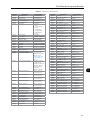
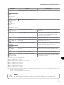
Summary of Revisions
Revision
2
Description
Chapter
1
First edition
-
2
General revision
-
Index
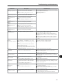
1 SAFETY INSTRUCTIONS................................................................... 1-1
1.1 SAFETY WARNINGS IN THE MANUAL.......................................................... 1-1
1.2 SAFETY WARNINGS IN THE PRODUCT......................................................... 1-1
1.3 PRELIMINARY RECOMMENDATIONS............................................................ 1-2
2 GENERAL INSTRUCTIONS............................................................... 2-1
2.1
2.2
2.3
2.4
2.5
ABOUT THE MANUAL.................................................................................. 2-1
TERMS AND DEFINITIONS........................................................................... 2-1
ABOUT THE CFW-11.................................................................................... 2-4
IDENTIFICATION LABELS FOR THE CFW-11............................................... 2-15
RECEIVING AND STORAGE........................................................................ 2-17
3 INSTALLATION AND CONNECTION................................................ 3-1
3.1 MECHANICAL INSTALLATION...................................................................... 3-1
3.1.1 Installation Environment..................................................................... 3-1
3.1.2 Mounting Considerations.................................................................... 3-2
3.1.3 Cabinet Mounting............................................................................... 3-9
3.1.4 Installation of the Inverter Hoisting Eyes - Frame Size E.................... 3-12
3.1.5 Installation of the Inverter with Nema1 Kit (Option, CFW11....T...ON1...)
on a Wall - Frame Size E .......................................................................................3-13
3.1.6 Access to the Control and Power Terminal Strips............................... 3-13
3.1.7 Removal of the Cable Passage Plate - Frame Size E........................... 3-15
3.1.8 HMI Installation at the Cabinet Door or Command Panel
(Remote HMI)............................................................................................. 3-16
3.2 ELECTRICAL INSTALLATION....................................................................... 3-16
3.2.1 Identification of the Power and Grounding Terminals........................ 3-17
3.2.2 Power / Grounding Wiring and Fuses............................................... 3-22
3.2.3 Power Connections............................................................................ 3-33
3.2.3.1 Input Connections............................................................... 3-36
3.2.3.1.1 IT Networks.......................................................... 3-37
3.2.3.1.2 Command Fuses of Pre-charge Circuit.................. 3-39
3.2.3.2 Dynamic Braking................................................................. 3-40
3.2.3.2.1 Sizing the Braking Resistor................................... 3-40
3.2.3.2.2 Installation of the Braking Resistor - Frame Sizes
B, C, D and E....................................................................... 3-43
3.2.3.3 Output Connections............................................................. 3-44
3.2.4 Grounding Connections.................................................................... 3-46
3.2.5 Control Connections.......................................................................... 3-47
3.2.6 Typical Control Connections.............................................................. 3-53
3.3 SAFETY STOP FUNCTION........................................................................... 3-56
3.3.1 Installation........................................................................................ 3-58
3.3.2 Operation......................................................................................... 3-58
3.3.2.1 Truth Table.......................................................................... 3-58
3.3.2.2 State of Inverter, Fault and Alarm Related to Safety
Stop Function.................................................................................. 3-59
3.3.2.3 STO Status Indication.......................................................... 3-59
3.3.2.4 Periodic Test......................................................................... 3-60
Index
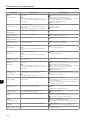
3.3.3 Examples of Wiring Diagrams of Inverter Control Signal.................. 3-60
3.3.4 Technical Specifications..................................................................... 3-61
3.3.4.1 Electrical Control Characteristics......................................... 3-61
3.3.4.2 Operational Safety Characteristics....................................... 3-61
3.3.4.3 Certification......................................................................... 3-62
3.4 INSTALLATION ACCORDING TO THE EUROPEAN DIRECTIVE OF
ELECTROMAGNETIC COMPATIBILITY............................................................... 3-63
3.4.1 Conformal Installation...................................................................... 3-63
3.4.2 Standard Definitions......................................................................... 3-63
3.4.3 Emission and Immunity Levels........................................................... 3-64
4 KEYPAD AND DISPLAY..................................................................... 4-1
4.1 INTEGRAL KEYPAD - HMI-CFW11................................................................ 4-1
4.2 PARAMETERS ORGANIZATION..................................................................... 4-4
5 FIRST TIME POWER-UP AND START-UP............................................ 5-1
5.1 PREPARE FOR START-UP............................................................................... 5-1
5.2 START-UP..................................................................................................... 5-2
5.2.1 Password Setting in P0000.................................................................. 5-2
5.2.2 Oriented Start-Up................................................................................ 5-3
5.2.3 Setting Basic Application Parameters................................................... 5-4
5.3 SETTING DATE AND TIME............................................................................ 5-8
5.4 BLOCKING PARAMETERS MODIFICATION.................................................... 5-9
5.5 HOW TO CONNECT A PC............................................................................ 5-9
5.6 FLASH MEMORY MODULE............................................................................ 5-9
6 TROUBLESHOOTING AND MAINTENANCE..................................... 6-1
6.1
6.2
6.3
6.4
6.5
OPERATION OF THE FAULTS AND ALARMS.................................................. 6-1
FAULTS, ALARMS AND POSSIBLE CAUSES.................................................... 6-2
SOLUTIONS FOR THE MOST FREQUENT PROBLEMS.................................... 6-8
INFORMATION NECESSARY FOR CONTACTING TECHNICAL SUPPORT....... 6-8
PREVENTIVE MAINTENANCE....................................................................... 6-9
6.5.1 Cleaning Instructions........................................................................ 6-10
7 OPTION KITS AND ACCESSORIES .................................................. 7-1
7.1 OPTION KITS............................................................................................... 7-1
7.1.1 Nema 1 Protection Degree - Frame Sizes B, C and E........................... 7-1
7.1.2 Safety Stop Function............................................................................ 7-1
7.1.3 24 Vdc External Control Power Supply................................................ 7-1
7.2 ACCESSORIES.............................................................................................. 7-2
7.2.1 Use of External Dynamic Braking Module DBW03............................... 7-4
Index
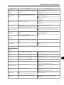
8 TECHNICAL SPECIFICATIONS ......................................................... 8-1
8.1 POWER DATA............................................................................................... 8-1
8.2 ELECTRONICS/GENERAL DATA.................................................................... 8-7
8.2.1 Codes and Standards.......................................................................... 8-8
8.3 MECHANICAL DATA..................................................................................... 8-9
8.4 NEMA 1 KITS.............................................................................................. 8-16
Index
Safety Instructions
1 SAFETY INSTRUCTIONS
This manual provides information for the proper installation and
operation of the CFW-11 frequency inverter.
Only trained and qualified personnel should attempt to install,
start-up, and troubleshoot this type of equipment.
1
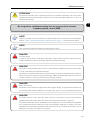
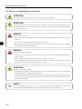
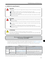
1.1 SAFETY WARNINGS IN THE MANUAL
The following safety warnings are used in this manual:
DANGER!
The procedures recommended in this warning have the purpose of protecting the user against death,
serious injuries and considerable material damage.
DANGER!
Les procédures concernées par cet avertissement sont destinées à protéger l'utilisateur contre des
dangers mortels, des blessures et des détériorations matérielles importantes.
ATTENTION!
The procedures recommended in this warning have the purpose of avoiding material damage.
NOTE!
The information mentioned in this warning is important for the proper understanding and good
operation of the product.
1.2 SAFETY WARNINGS IN THE PRODUCT
The following symbols are attached to the product and require special attention:
Indicates a high voltage warning.
Electrostatic discharge sensitive components.
Do not touch them.
Indicates that a ground (PE) must be connected securely.
Indicates that the cable shield must be grounded.
Indicates a hot surface warning.
1-1
Safety Instructions
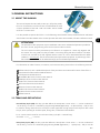
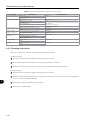
1.3 PRELIMINARY RECOMMENDATIONS
DANGER!
Only trained personnel, with proper qualifications, and familiar with the CFW-11 and associated
machinery shall plan and implent the installation, starting, operation, and maintenance of this
equipment.
The personnel shall follow all the safety instructions described in this manual and/or defined by the
local regulations.
Failure to comply with the safety instructions may result in death, serious injury, and equipment damage.
1
DANGER!
Seulement personnes avec la qualification adéquate et familiarisation avec le CFW-11 et équipements
associés doivent planifiquer ou implementer l'installation, mise en marche, operation et entretien
de cet équipement.
Cettes personnes doivent suivre toutes les instructions de sécurités indiquées dans ce manuel, et/ou
définies par normes locales.
L'inobservance des instructions de sécurité peut résulter en risque de vie et/ou dommages de cet
équipement.
NOTE!
For the purpose of this manual, qualified personnel are those trained and able to:
1. Install, ground, power-up, and operate the CFW-11 according to this manual and to the current
legal safety procedures.
2. Use the protection equipment according to the established regulations.
3. Provide first aid.
DANGER!
Always disconnect the main power supply before touching any electrical device associated with the
inverter.
Several components may remain charged with high voltage and/or in movement (fans), even after
the AC power supply has been disconnected or turned off.
Wait at least 10 minutes to guarantee the fully discharge of capacitors.
Always connect the equipment frame to the ground protection (PE).
DANGER!
Débranchez toujours l'alimentation principale avant d'entrer en contact avec un appareil électrique
associé au variateur. Plusieurs composants peuvent rester chargés à un potentiel électrique élevé et/
ou être en mouvement (ventilateurs), même après la déconnexion ou la coupure de l'alimentation
en courant alternatif.
Attendez au moins 10 minutes que les condensateurs se déchargent complètement.
Raccordez toujours la masse de l'appareil à une terre protectrice (PE).
1-2
Safety Instructions
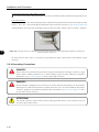
ATTENTION!
The electronic boards contain components sensitive to electrostatic discharges. Do not touch the
components and terminals directly. If needed, touch first the grounded metal frame or wear an
adequate ground strap.
1
Do not perform a withstand voltage test on any part of the inverter!
If needed, please, consult WEG.
NOTE!
Frequency inverters may cause interference in other electronic devices. Follow the recommendations
listed in chapter 3 INSTALLATION AND CONNECTION on page 3-1, to minimize these effects.
NOTE!
Fully read this manual before installing or operating the inverter.
DANGER!
Crushing Hazard
In order to ensure safety in load lifting applications, electric and/or mechanical devices must be
installed outside the inverter for protection against accidental fall of load.
DANGER!
This product was not designed to be used as a safety element. Additional measures must be taken
so as to avoid material and personal damages.
The product was manufactured under strict quality control, however, if installed in systems where its
failure causes risks of material or personal damages, additional external safety devices must ensure
a safety condition in case of a product failure, preventing accidents.
DANGER!
Risque d'écrasement
Afin d'assurer la sécurité dans les applications de levage de charges, les équipements électriques et/
ou mécaniques doivent être installés hors du variateur pour éviter une chute accidentelle des charges.
DANGER!
Ce produit n'est pas conçu pour être utilisé comme un élément de sécurité. Des précautions
supplémentaires doivent être prises afin d'éviter des dommages matériels ou corporels.
Ce produit a été fabriqué sous un contrôle de qualité conséquent, mais s'il est installé sur des systèmes
où son dysfonctionnement entraîne des risques de dommages matériels ou corporels, alors des
dispositifs de sécurité externes supplémentaires doivent assurer des conditions de sécurité en cas de
défaillance du produit, afin d'éviter des accidents.
1-3
Safety Instructions
1
1-4
General Instructions
2 GENERAL INSTRUCTIONS
2.1 ABOUT THE MANUAL
This manual exposes how to install, to start-up in V/f (scalar) mode,
the main characteristics and shows how to troubleshoot the most
common problems of the 500...600 V and 500...690 V models
of CFW-11 inverter series.
It is also possible to operate the CFW-11 in the following control modes: V V W, Sensorless Vector and Vector
with Encoder. For further details on the inverter operation with other control modes, refer to the software manual.
ATTENTION!
The operation of this equipment requires installation instructions and detailed operation provided in
the user's manual, programming manual and communication manuals.
The user's manual and the parameters quick reference are supplied in a hard copy together with
the inverter. The user guides are also provided in a hard copy along with the accessories. The other
manuals are included on the CD supplied with the inverter or can be downloaded from the WEG
website at - www.weg.net. The CD should always be kept with the equipment. A printed copy of the
files available on the CD can be ordered through your local WEG representative.
For information on other functions, accessories, and communication, please refer to the following manuals:
Software Manual, with a detailed description of the parameters and advanced functions of the CFW-11.
Incremental Encoder Interface Module Manual.
I/O Expansion Module Manual.
RS-232/RS-485 Serial Communication Manual.
CANopen Slave Communication Manual.
Anybus-CC Communication Manual.
DeviceNet Communication Manual.
Ethercat Communication Manual.
Profibus DP Communication Manual.
Symbinet Communication Manual.
SoftPLC Manual.
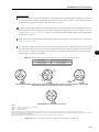
2.2 TERMS AND DEFINITIONS
Normal Duty Cycle (ND): the duty cycle that defines the steady state current value Inom-ND and an overload of
110 % during 1 minute. It is selected by programming P0298 (Application) = 0 (Normal Duty – ND). It must
be used for driving motors that are not subject in that application to high torques with respect to their rated
torque, when operating at constant speed, during start, acceleration or deceleration.
Inom-ND: inverter rated current for use with normal duty cycle (ND = Normal Duty).
Overload: 1.1 x Inom-ND / 1 minute.
Heavy Duty Cycle (HD): the duty cycle that defines the steady state current value Inom-HD and an overload of
150 % during 1 minute. It is selected by programming P0298 (Application) = 1 (Heavy Duty – HD). It must be
2-1
2
General Instructions
used for driving motors that are subject in that application to high torques with respect to their rated torque,
when operating at constant speed, during start, acceleration or deceleration.
Inom-HD: inverter rated current for use with heavy duty cycle (HD = Heavy Duty).
Overload: 1.5 x Inom-HD / 1 minute.
Rectifier: the input circuit of the inverters that converts the input AC voltage into DC; it is made of thyristors
and power diodes.
Pre-charge Circuit: it charges the DC link capacitors with a limited current, thus avoiding higher current peaks
when powering the inverter.
2
DC Link: inverter intermediate circuit; DC voltage obtained from the rectification of the AC input voltage or
from an external power supply. It feeds the inverter output IGBT bridge.
U, V, W Arms: set of two IGBTs forming the inverter output phases U, V, and W.
IGBT: Insulated Gate Bipolar Transistor; it is the output inverter bridge basic component, working as an electronic
switch either in the saturated (closed switch) or in the cut off mode (open switch).
Braking IGBT: works as a switch to activate the braking resistors; it is controlled by the DC bus voltage level.
Gate Driver: circuit used to turn-on and turn-off the IGBTs.
PWM: Pulse Width Modulation; a pulsed voltage that feeds the motor.
Switching Frequency: it is the inverter bridge IGBTs commutation frequency, normally specified in kHz. Also
known as carrier frequency.
Heatsink: It is a metal part designed for dissipating the heat generated by the power semiconductors.
MOV: Metal Oxide Varistor.
PE: Protective Earth.
RFI Filter: Radio-Frequency Interference Filter; a filter that avoids interference in the radiofrequency range.
PTC: it is a resistor, whose resistance value in ohms increases proportionally to the temperature increase, being
used as temperature sensor in motors.
NTC: it is a resistor, whose resistance value in ohms decreases proportionally to the temperature increase, being
used as temperature sensor in power modules.
HMI: Human-Machine Interface; it is the device that allows the control of the motor, the visualization and the
modification of the inverter parameters; it's also known as keypad. The CFW-11 HMI presents keys for
commanding the motor, navigation keys and a graphic LCD display.
FLASH Memory: it is the nonvolatile memory that can be electrically written and erased.
2-2
General Instructions
RAM Memory: Random Access Memory (volatile).
USB: Universal Serial Bus; it's a serial bus standard that allows devices to be connected using the Plug and
Play concept.
PE: Protective Earth.
General Enable: when activated, it accelerates the motor via acceleration ramp. When deactivated, this
function immediately blocks the PWM pulses. The general enable function can be controlled through a digital
input programmed for this function or via serial communication.
Run/Stop: inverter function that when activated (Run) accelerates the motor with the acceleration ramp until
reaching the speed reference, and when deactivated (Stop) decelerates the motor with the deceleration ramp
down to stop. It can be commanded through a digital input programmed for that function or via serial
communication. The HMI keys
(Run) and
(Stop) work in a similar manner.
STO: Safe Torque Off; functional safety function available as an option in CFW-11 inverter series; when STO
function is enabled the inverter guarantees that there is no movement of the motor shaft; it's also called safety
stop function in CFW-11 documentation.
PLC: Programmable Logic Controller.
TBD: value to be defined.
ac: alternated current.
dc: direct current.
Amp, A: ampere.
°C: Celsius degree.
CFM: Cubic Feet per Minute; unit of flow.
cm: centimeter.
°F: Fahrenheit degree.
ft: foot.
Hz: hertz.
hp: horse power = 746 watts; unit of power, used to indicate the mechanical power of electrical motors.
in: inch.
kg: kilogram = 1000 grams.
kHz: kilohertz = 1000 hertz.
2-3
2
General Instructions
l/s: liters per second.
lb: pound.
m: meter.
mA: miliampere = 0.001 ampere.
min: minute.
mm: millimeter.
2
ms: millisecond = 0.001 seconds.
N.m: newton meter; unit of torque.
rms: root mean square; effective value.
rpm: revolutions per minute; unit of speed.
s: second.
V: volts.
Ω: ohms.
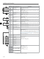
2.3 ABOUT THE CFW-11
The CFW-11 frequency inverter is a high performance product designed for speed and torque control of threephase induction motors. The main characteristic of this product is the “Vectrue” technology, which has the
following advantages:
Scalar control (V/f), V V W, or vector control programmable in the same product.
The vector control may be programmed as “sensorless” (which means standard motors without using
encoders) or as “vector control” with the use of an encoder.
The “sensorless” control allows high torque and fast response, even in very low speeds or at the starting.
The “vector with encoder” control allows high speed precision for the whole speed range (even with a
standstill motor).
"Optimal Braking" function for the vector control, allowing the controlled braking of the motor and avoiding
the use of the braking resistor in some applications.
“Self-Tuning” feature for vector control. It allows the automatic adjustment of the regulators and control
parameters from the identification (also automatic) of the motor parameters and load.
2-4
General Instructions
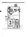
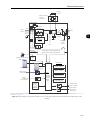
DC+ BR
= DC bus connection
DC- = Braking resistor connection
RFI Filter/MOVs (*)
R/L1
Mains power S/L2
supply
T/L3
Precharge
DC Link
chokes
U/T1
V/T2 Motor
W/T3
DC Link
capacitor bank
Three-phase
rectifier
RFI filter
PE
Inverter
with IGBT
transistors
PE
Feedback: - voltage
- current
2
POWER
CONTROL
PC
SuperDrive G2 software
WLP software
USB
Control power supply and interfaces
between power and control
Accessories
I/O expansion
(Slot 1 - white)
Keypad (remote)
Keypad
Digital
inputs
(DI1 to DI6)
Encoder interface
(Slot 2 - yellow)
CC11
Control
board with
a 32 bits
"RISC"
CPU
Analog
inputs
(AI1 and AI2)
COMM 1
(Slot 3 - green)
COMM 2
(anybus) (Slot 4 )
FLASH
Memory
Module
MMF-03
Analog outputs
(AO1 and AO2)
Digital outputs
DO1 (RL1) to
DO3 (RL3)
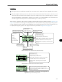
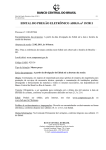
(*) The capacitor of RFI filter and MOV connected to the ground must be disconnected with IT and corner-grounded delta networks. Refer to item 3.2.3.1.1
IT Networks on page 3-37.
Figure 2.1 - Block diagram for the CFW -11 - frame sizes B, C, D and E
2-5
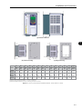
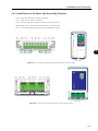
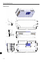
General Instructions
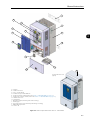
C
G
A
B
2
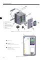
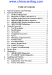
A – Mounting supports
(for through the wall mounting)
B – Heatsink
J
C –Top cover
D – Fan with mounting support
E – COMM 2 module (anybus)
F – Option board / accessory module
G –FLASH memory module MMF-03
H – Front cover
I – Keypad
J – SRB2A safety stop board
I
F
E
D
Figure 2.2 - Main components of the CFW-11 - frame sizes B, C and D
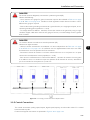
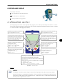
1
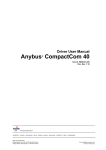
USB Connector
2
USB LED
Off: No USB connection
On/Flashing: USB communication is active
3
STATUS LED
Green: Normal operation with no fault or alarm
Yellow: Alarm condition
Flashing red: Fault condition
Figure 2.3 - LEDs and USB connector
2-6
H
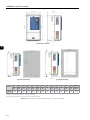
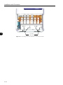
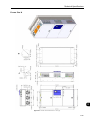
General Instructions
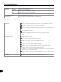
I
D
L
J
E
C
B
K
2
A
I
F
H
G
M
Inverter with Nema1 kit
(option)
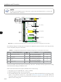
A – Keypad
B – Control rack cover
C – CC11 control board
D – FLASH memory module MMF-03
E – Control accessory module (refer to the section 7.2 ACCESSORIES on page 7-2)
F – Anybus-CC accessory module (refer to the section 7.2 ACCESSORIES on page 7-2)
G – Bottom front cover
H – Heatsink fan
I – Mounting supports (for through the wall mounting)
J – Hoisting eye
K – Rear part of the inverter (external part for flange mounting)
L – SRB4 safety stop board
M – Nema1 kit
Figure 2.4 - Main components of the CFW-11 - frame size E
2-7
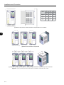
General Instructions
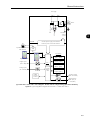
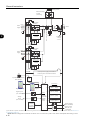
Braking
resistor
External braking
module
(Optional)
DC+
RFI filter/MOVs (*)
PC
SuperDrive G2 software
WLP software
POWER
CONTROL
Motor
IGBT
inverter
RFI filter
CPC 11
Pre-charge
control
PE
U/T1
V/T2
W/T3
DC link capacitor
bank
2
Three-phase
rectifier
R/L1
S/L2
T/L3
DC link
chokes
Power
supply
DC-
PE
Feedback:
- voltage
- current
Control power supply and interfaces
between power and control sections
USB
Accessories
I/O expansion
(Slot 1 - white)
Keypad (remote)
Keypad
Digital inputs
(DI1 to DI6)
CC11
Analog
inputs
(AI1 and AI2)
Control
board with
32-bit
“RISC”
CPU
FLASH
memory
module
Encoder interface
(Slot 2 - yellow)
COMM 1
(Slot 3 - green)
COMM 2
(anybus) (Slot 4)
Analog outputs
(AO1 and AO2)
Digital outputs
DO1 (RL1) to
DO3 (RL3)
(*) The RFI filter capacitor and MOV connected to the ground must be disconnected with IT and corner-grounded delta networks. Refer to item 3.2.3.1.1
IT Networks on page 3-37.
(a) Frame sizes F and G CFW-11 block diagram - Standard models with alternating current feeding
2-8
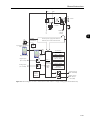
General Instructions
DC supply
DC+
DC-
POWER
CONTROL
PC
SuperDrive G2 software
WLP software
Motor
IGBT
inverter
PE
Feedback:
- voltage
- current
RFI filter
DC link capacitor
bank
U/T1
V/T2
W/T3
2
Control power supply and interfaces
between power and control sections
USB
Accessories
I/O expansion
(Slot 1 - white)
Keypad (remote)
Keypad
Digital inputs
(DI1 to DI6)
CC11
Analog inputs
(AI1 and AI2)
Control
Board with
32-bit
“RISC”
CPU
Encoder interface
(Slot 2 - yellow)
COMM 1
(Slot 3 - green)
COMM 2
(anybus) (Slot 4)
FLASH
memory
module
Analog outputs
(AO1 and AO2)
Digital outputs
DO1 (RL1) to
DO3 (RL3)
(b) Frame sizes F and G CFW-11 block diagram - Models with DC voltage feeding (Special DC Hardware)
Figure 2.5 - (a) and (b) Block diagram for the CFW-11 - frame size F and G
2-9
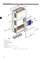
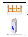
General Instructions
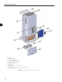
I
J
K
2
D
C
B
A
L
E
I
F
H
G
A - Keypad
B - Control rack cover
C - CC11 control board
D - FLASH memory module MMF-03
E - Control accessory module
F - Anybus-CC accessory module
G - Bottom front cover
H - Heatsink fan
I - Mounting supports (for surface mounting)
J - Hoisting eye
K - Rear part of the inverter (external part for flange mounting)
L - SRB3 safety stop board
Figure 2.6 - CFW-11 main components - frame sizes F, G
2-10
General Instructions
Braking
resistor
External braking
module
(Accessory)
DC+
DC-
RFI filter/MOVs (*)
Three-phase
Rectifier
R/L1
S/L2
T/L3
V/T2 Motor
W/T3
PE
PC
SuperDrive G2 software
WLP software
U/T1
CPC 11
Pre-charge
control
POWER
CONTROL
DC link capacitor bank
Power
supply
IGBT
inverter
RFI filter
2
PE
Feedback:
- voltage
- current
Control power supply and interfaces
between power and control sections
USB
Accessories
I/O Expansion
(Slot 1 - white)
Keypad (remote)
Keypad
Digital inputs
(DI1 to DI6)
Encoder Interface
(Slot 2 - yellow)
CC11
Control
board with
32-bit
“RISC”
CPU
Analog
inputs
(AI1 and AI2)
FLASH
memory
module
MMF-03
COMM 1
(Slot 3 - green)
COMM 2
(anybus) (Slot 4)
Analog outputs
(AO1 and AO2)
Digital outputs
DO1 (RL1) to
DO3 (RL3)
(*) The RFI filter capacitor and MOV connected to the ground must be disconnected with IT and corner-grounded delta networks. Refer to item 3.2.3.1.1
IT Networks on page 3-37.
Figure 2.7 - Block diagram of standard models of CFW-11 frame size H (584 A and 625 A Models) with alternating current
feeding
2-11
General Instructions
Braking resistor
External braking
module
(Accessory)
DC+
DC-
RFI filter/MOVs (*)
Three-phase
Rectifier
CPC 11-1
Pre-charge
control
PE
2
U/T1
V/T2 Motor
W/T3
DC link capacitor bank
R1/L1-1
Power S1/L2-1
supply
T1/L3-1
IGBT
inverter
PE
RFI filter
Feedback:
- voltage
- current
RFI filter/MOVs (*)
Three-phase
rectifier
R2/L1-2
Power S2/L2-2
supply T2/L3-2
PE
PC
SuperDrive G2 software
WLP software
CPC 11-2
Pre-charge
control
POWER
CONTROL
Control power supply and interfaces
between power and control sections
USB
Accessories
I/O expansion
(Slot 1 - white)
Keypad (remote)
Keypad
Digital inputs
(DI1 to DI6)
CC11
Analog
inputs
(AI1 and AI2)
Control
board with
32-bit
“RISC”
CPU
FLASH
memory
module
MMF-03
Encoder interface
(Slot 2 - yellow)
COMM 1
(Slot 3 - green)
COMM 2
(anybus) (Slot 4)
Analog outputs
(AO1 and AO2)
Digital outputs
DO1 (RL1) to
DO3 (RL3)
(*) The RFI filter capacitor and MOV connected to the ground must be disconnected with IT and corner-grounded delta networks. Refer to item 3.2.3.1.1
IT Networks on page 3-37.
Figure 2.8 - Block diagram of standard models of CFW-11 frame size H (758 A and 804 A models)with alternating current
2-12
General Instructions
DC power supply
DC+
DC-
U/T1
V/T2
Motor
DC link capacitor bank
W/T3
PC
SuperDrive G2 software
WLP software
POWER
CONTROL
IGBT
inverter
RFI filter
PE
Feedback:
- voltage
- current
2
Control power supply and interfaces
between power and control sections
USB
Accessories
I/O expansion
(Slot 1 - white)
Keypad (remote)
Keypad
Digital inputs
(DI1 to DI6)
CC11
Analog inputs
(AI1 and AI2)
Control
board with
32-bit
“RISC”
CPU
FLASH
memory
module
MMF-03
Encoder interface
(Slot 2 - yellow)
COMM 1
(Slot 3 - green)
COMM 2
(anybus) (Slot 4)
Analog outputs
(AO1 and AO2)
Digital outputs
DO1 (RL1) to
DO3 (RL3)
Figure 2.9 - Block diagram of CFW-11 frame size H models with DC voltage feeding (special hardware DC)
2-13
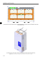
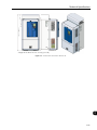
General Instructions
I
J
K
D
2
C
B
A
L
E
F
I
H
A - Keypad
B - Control rack cover
C - CC11 control board
D - FLASH memory module MMF-03
E - Control accessory module
F - Anybus-CC accessory module
G - Bottom front cover
H - Heatsink fan
I - Mounting supports (for surface mounting)
J - Hoisting eye
K - Rear part of the inverter (external part for flange mounting)
L - SRB3 safety stop board
Figure 2.10 - CFW-11 main components - frame size H
2-14
G
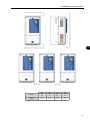
General Instructions
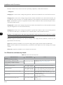
2.4 IDENTIFICATION LABELS FOR THE CFW-11
There are two nameplates on the CFW-11: one complete nameplate is affixed to the side of the inverter and
a simplified one is located under the keypad. The nameplate under the keypad allows the identification of the
most important characteristics of the inverter even if they are mounted side-by-side.
CFW-11 model
WEG part number
Manufacturing date (48 corresponds
to week and H to year)
Serial number
Maximum surrounding air temperature
Rated output data (voltage, number of phases,
rated currents for operation with ND and HD
overload cycles, overload currents for 1 min
and 3 s, frequency range)
Inverter net weight
Rated input data (voltage, number of phases,
rated currents for operation with ND and HD
overload cycles, frequency)
Current specifications for operation with
normal overload cycle (ND)
Current specifications for operation with
heavy overload cycle (HD)
(a) Nameplate affixed to the side of the inverter
CFW-11 model
WEG part number
BRCFW110044T6OYZ
48 H
11799018
SERIAL#: 1013933619
Manufacturing date
(48 corresponds to week and H to year)
Serial number
(b) Nameplate located under the keypad
Figure 2.11 - (a) and (b) Nameplates
1
Nameplate affixed to the
side of the heatsink
2
Nameplate under the keypad
1
2
Figure 2.12 - Location of the nameplates
2-15
2
2-16
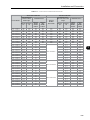
Market
identification
(defines
the manual
language and
the factory
settings)
2 characters
Field
description
Available
options
WEG
CFW-11
frequency
inverter
series
CFW11
T
T = threephase power
supply
Rated output Number of
power phases
current for
use with the
Normal Duty
(ND) cycle
0044
Option kit
S
5 = 500...600 V (8) S =
6 = 500...690 V (7) standard
product
O=
product with
option kit
Power supply
voltage
6
Blank =
standard (1)
N1 =
Nema1(6)
21 = IP21 (7)
Enclosure
type
__
Blank =
standard (2)
IC = no
keypad
(blind cover)
Keypad (HMI)
__
Blank =
standard (3)
NB =
without
braking
IGBT (4)
Braking
__
(5)
Blank =
standard
internal
RFI filter
NF =
without
RFI filter
RFI filter
__
Blank =
standard (safety
stop function is
not available)
Y = safety
stop according
to EN-954-1
category 3
Safety stop
__
Blank = standard
(not available)
W = 24 Vdc
external power
supply for control
24 Vdc external
power supply for
control
__
Blank=
standard
DC= feeding
with DC (only
valid for frame
sizes F and G)
E.g.: H1 =
special
hardware #1
Special
hardware
__
Blank =
standard
E.g.:
S1 =
special
software #1
Special
software
__
Refer to chapter 7 OPTION KITS AND ACCESSORIES on page 7-1, to check option kit availability for each inverter
model
Refer to chapter 8 TECHNICAL SPECIFICATIONS on page
8-1, for a list of models for the CFW-11 series and for a
complete inverter's technical specification
(1)Standard for frame size B: IP21.
Standard for frame sizes E, F and G: IP20.
Standard for frame sizes F and G with special hardware DC: IP00.
(2)Standard keypad (HMI-CFW11).
(3)
Braking transistor (IGBT) is incorporated in all models of frame sizes B, C, D, and E as standard.
(4) Only valid for frame sizes D and E.
(5) Only valid for frame sizes B and D.
(6) Only valid for frame sizes B, D and E.
(7) Only valid for frame sizes D, E, F and G.
(8) Only valid for frame size B.
BR
Example
AVAILABLE OPTION KITS (CAN BE INSTALLED IN THE PRODUCT FROM THE FACTORY)
2
INVERTER MODEL
HOW TO CODIFY THE CFW-11 MODEL (CODIFICATION)
Character
that
identifies
the code
end
Z
General Instructions
General Instructions
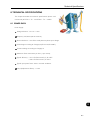
2.5 RECEIVING AND STORAGE
The CFW-11 inverters from the frame sizes F, G and H models are supplied packed in wooden boxes.
There is an identification label affixed to the outside of the package, identical to the one affixed to the side of
the inverter.
To open the package:
1. Remove the package front cover.
2. Take out the polystyrene foam protection.
2
Verify whether:
The CFW-11 nameplate corresponds to the purchased model.
Any damage occurred during transportation.
Report any damage immediately to the carrier that delivered your CFW-11 inverter.
If the CFW-11 is not installed soon, store it in a clean and dry location (temperature between -25 °C and 60 °C
(-13 °F and 140 °F)), with a cover to prevent dust accumulation inside it.
ATTENTION!
When the inverter is stored for a long period, it becomes necessary to perform the capacitor reforming.
Refer to the procedure in the section 6.5 PREVENTIVE MAINTENANCE on page 6-9, Table 6.3
on page 6-9.
2-17
General Instructions
2
2-18
Installation and Connection
3 INSTALLATION AND CONNECTION
This chapter provides information on installing and wiring the CFW-11.
The instructions and guidelines listed in this manual shall be followed
to guarantee personnel and equipment safety, as well as the proper
operation of the inverter.
3.1 MECHANICAL INSTALLATION
3.1.1 Installation Environment
NOTE!
The inverter are designed for indoor use only.
Avoid installing the inverter in an area with:
3
Direct exposure to sunlight, rain, high humidity, or sea-air.
Inflammable or corrosive gases or liquids.
Excessive vibration.
Dust, metallic particles, and oil mist.
Environment conditions for the operation of the inverter:
Temperature (standard conditions (surrounding the inverter), no frost allowed):
- 10 ºC to 50 ºC (14 ºF to 122 ºF) for frame sizes B, C and D models.
- 10 ºC to 45 ºC (14 ºF to 113 ºF) for frame sizes E, F and G models.
- 10 ºC to 40 ºC (14 ºF to 104 ºF) for frame size H.
From 40 ºC to 45 ºC (104 ºF to 113 ºF) for frame size H: 1 % of current derating for each celsius degree
above maximum temperature as specified in item above.
From 50 ºC to 60 ºC (122 °F to 140 °F) for frame sizes B, C and D models and from 45 ºC to 55 ºC
(113 ºF to 131 ºF) for frame sizes F, G and H models: 2 % of current derating for each Celsius degree above
maximum temperature as specified in item above.
Altitude: up to 1000 m (3.300 ft) above sea level - standard conditions (no derating required).
From 1000 m to 4000 m (3.300 ft to 13.200 ft) above sea level - 1 % of current derating for each 100 m
(330 ft) above 1000 m (3.300 ft) altitude.
From 2000 m to 4000 m (6.600 ft to 13.200 ft) above sea level - reduction of maximum voltage (600 V for
500...600 V models and 690 V for 500...690 V models) of 1.1 % for each 100 m (330 ft) above 2000 m
(6.600 ft).
Note that derating specified in items above applies also to dynamyc braking IGBT (columm effective braking
current (Ieffective) of Table 3.9 on page 3-42).
3-1
Installation and Connection
Humidity: from 5 % to 95 % non-condensing.
Pollution degree: 2 (according to EN50178 and UL508C) with non-conductive pollution. Condensation
shall not originate conduction through the accumulated residues.
3.1.2 Mounting Considerations
Consult the inverter weight at the Table 8.1 on page 8-2, Table 8.2 on page 8-3, Table 8.3 on page 8-4
and Table 8.4 on page 8-5.
Mount the inverter in the upright position on a flat and vertical surface.
External dimensions and fixing holes position according to the Figure 3.1 on page 3-3, Figure 3.2 on page
3-4 and Figure 3.3 on page 3-5. Refer to the section 8.3 MECHANICAL DATA on page 8-9, for more
details.
First mark the mounting points and drill the mouting holes. Then, position the inverter and firmly tighten the
screws in all four corners to secure the inverter.
3
Minimum mounting clearances requirements for proper cooling air circulation are specified in Figure 3.4 on page
3-6, Figure 3.5 on page 3-7 and Figure 3.6 on page 3-8.
Inverters of frame size B can be arranged side-by-side with no clearance required between them. In this case,
the top cover must be removed as shown in Figure 3.4 on page 3-6.
Do not install heat sensitive components right above the inverter.
ATTENTION!
When arranging two or more inverters vertically, respect the minimum clearance A + B (Figure 3.4 on
page 3-6, Figure 3.5 on page 3-7 and Figure 3.6 on page 3-8) and provide an air deflecting
plate so that the heat rising up from the bottom inverter does not affect the top inverter.
ATTENTION!
Provide conduit for physical separation of the signal, control, and power conductors (refer to section
3.2 ELECTRICAL INSTALLATION on page 3-16).
3-2
Installation and Connection
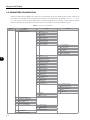
(a) Dimension External
3
Air flow
Air flow
Max. 3 mm
(0.12 in)
(b) Surface Mounting
(c) Flange Mounting
A1
B1
C1
D1
E1
a2
b2
c2
a3
b3
c3
d3
e3
Torque (*)
Model
mm
(in)
mm
(in)
mm
(in)
mm
(in)
mm
(in)
mm
(in)
mm
(in)
M
mm
(in)
mm
(in)
M
mm
(in)
mm
(in)
N.m
(lbf.in)
Frame
Size B
190
(7.48)
293
(11.53)
227
(8.94)
71
(2.79)
316
(12.44)
150
(5.91)
300
(11.81)
M5
175
(6.89)
285
(11.22)
M5
179
(7.05)
271
(10.66)
5.0
(44.2)
Frame
Size C
220
(8.67)
378
293
(14.88) (11.52)
136
(5.36)
405
(15.95)
150
(5.91)
375
(14.77)
M6
195
(7.68)
365
(14.38)
M6
205
(8.08)
345
(13.59)
8.5
(75.2)
Frame
Size D
300
504
305
(11.81) (19.84) (12.00)
135
(5.32)
550
(21.65)
200
(7.88)
525
(20.67)
M8
275
517
(10.83) (20.36)
M8
285
485
(11.22) (19.09)
20.0
(177.0)
Tolerances for dimensions d3 and e3: +1.0 mm (+0.039 in).
Tolerances for remaining dimensions: ±1.0 mm (±0.039 in).
(*) Recommended torque for the inverter mounting (valid for c2 and c3).
Figure 3.1 - (a) to (c) Mechanical installation details - frame sizes B, C and D
3-3
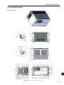
Installation and Connection
335 (13.2)
358 (14.1)
E1
620 (24.4)
B1
675 (26.6)
C1
168 (6.6)
D1
(a) Dimension External
3
275 (10.8)
a3
e3
635 (25)
b2
650 (25.6)
200 (7.8)
a2
d3
∅ c3
∅ c2
Air flow
Air flow
Max. 3 (0.12)
(b) Surface Mounting
(c) Flange Mounting
A1
B1
C1
D1
E1
a2
b2
c2
a3
b3
c3
d3
e3
Torque (*)
Model
mm
(in)
mm
(in)
mm
(in)
mm
(in)
mm
(in)
mm
(in)
mm
(in)
M
mm
(in)
mm
(in)
M
mm
(in)
mm
(in)
N.m
(ibf.in)
Frame
Size E
335
(13.2)
375
(26.6)
358
(14.1)
168
(6.6)
620
(24.4)
200
(7.8)
650
(25.6)
M8
275
(10.8)
635
(25)
M8
315
615
(24.21) (24.21)
Tolerances for dimensions d3 and e3: +1.0 mm (+0.039 in).
Tolerances for remaining dimensions: ±1.0 mm (±0.039 in).
(*) Recommended torque for the inverter mounting (valid for c2 and c3).
Figure 3.2 - (a) to (c) Mechanical installation details - mm (in) - frame size E
3-4
20.0
(177.0)
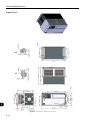
Installation and Connection
A1
A1
B1
B1
E1
E1
C1
C1
D1
D1
(a) Dimension External
a2
a3
e3
3
b3
b2
a2
d3
c2
Air flow
Fluxo
de Ar
Air de
flow
Fluxo
Ar
Max.
3 (0.12)
mm
Max. 3mm
(0.12 in)
(b) Surface mounting
Modelo
C1
(c) Flange mounting
A1
B1
C1
D1
E1
a2
b2
c2
a3
b3
c3
d3
e3
mm
(in)
mm
(in)
mm
(in)
mm
(in)
mm
(in)
mm
(in)
mm
(in)
M
mm
(in)
mm
(in)
M
mm
(in)
mm
(in)
A1
B1
Model
mm
(in)
mm
(in)
Frame
Size F
430
(16.93)
1156
(45.51)
Tolerância
d3 e e3: +1.0mm
(+0.039in) 150
360 das cotas169
1234
Tolerância das demais cotas: 1.0mm ( 0.039in)
(14.17) (6.65) (48.58) (5.91)
Frame
Size G
535
(21.06)
1190
(46.85)
426
(16.77)
202
(7.95)
1264
(49.76)
Frame
Size H
626.0
(27.01)
1319.7
(51.96)
420.8
(16.57)
171.7
(6.76)
1414.0
(55.67)
Mec F
mm
Mec G
(in)
c3
430 D1
1156
360 E1169
(16.93) (45.51) (14.17) (6.65)
mm
(in)
mm
(in)
1234a2 150
(48.58) (5.91)
mm
(in)
b2 M10
1200
(47.24)
mm
(in)
c2 1185
350
(13.78) (46.65)
a3
M10
391 b3
1146
(15.39) (45.12)
c3
d3
e3
mm
(in)
M
mm
(in)
mm
(in)
M
mm
(in)
1200
(47.24)
M10
350
(13.78)
1185
(46.65)
M10
391
(15.39)
1146
(45.12)
200
(7.87)
1225
(48.23)
M10
400
(15.75)
1220
(48.03)
M10
495
(19.49)
1182
(46.53)
175.0
(6.89)
1350.0
(53.15)
M10
595.0
(23.43)
1345.0
(52.95)
M10
647.0
(25.47)
1307.0
(51.46)
Tolerance for dimensions d3 and e3: +1.0 mm (+0.039 in).
Tolerance for the other dimensions: ±1.0 mm (±0.039 in).
Figure 3.3 - (a) to (c) Mechanical installation details - frame sizes F, G and H
3-5
Installation and Connection
A
B
C
Model
mm
(in)
mm
(in)
mm
(in)
Frame
Size B
40
(1.57)
45
(1.77)
10
(0.39)
Frame
Size C
110
(4.33)
130
(5.12)
10
(0.39)
Frame
Size D
110
(4.33)
130
(5.12)
10
(0.39)
Tolerance: ±1.0 mm (±0.039 in)
(a) Minimum top, bottom, and front clearance requirements for air circulation
≥ 30.0 [1.18]
≥ 30.0 [1.18]
3
* Dimensions in mm [in]
(b) Minimum side clearance requirements
(c) Frame size: side-by-side mounting - No clearance required between inverters if top cover is removed
Figure 3.4 - (a) to (c) Free spaces around inverter for ventilation - frame sizes B, C and D
3-6
Installation and Connection
3
A
B
C
D
Model
mm
(in)
mm
(in)
mm
(in)
mm
(in)
Frame
Size E
150
(5.91)
250
(9.84)
20
(0.78)
80
(3.15)
Figure 3.5 - Free spaces around inverter for ventilation - frame size E
3-7
A
Installation and Connection
3
B
C
D
D
A
B
C
D
Model
mm
(in)
mm
(in)
mm
(in)
mm
(in)
Frame Sizes
F, G and H
150
(5.91)
250
(9.84)
20
(0.78)
80
(3.15)
Tolerance: ±1.0 mm (±0.039 in).
Figure 3.6 - Free spaces around inverter for ventilation - frame sizes F, G and H
3-8
Installation and Connection
3.1.3 Cabinet Mounting
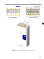
There are two possibilities for mounting the inverter: through the wall mounting or flange mounting (the heatsink
is mounted outside the cabinet and the cooling air of the power module is kept outside the enclosure). The
following information shall be considered in these cases:
Surface Assembly:
Provide adequate exhaustion so that the internal cabinet temperature is kept within the allowable operating
range of the inverter.
The power dissipated by the inverter at its rated condition, as specified in Table 8.1 on page 8-2 to Table
8.4 on page 8-5 "Dissipated power in Watts - Through the wall mounting".
The cooling air flow requirements, as shown in Table 3.1 on page 3-10.
The position and diameter of the mounting holes, according to Figure 3.1 on page 3-3, Figure 3.2 on
page 3-4 and Figure 3.3 on page 3-5.
Flange Assembly:
Frame Sizes B, C and D:
The losses specified in Table 8.1 on page 8-2 and Table 8.3 on page 8-4 "Dissipated power in Watts Flange mounting" will be dissipated inside the cabinet. The remaining losses (power module) will be dissipated
through the vents.
The mounting supports shall be removed and repositioned as illustrated in Figure 3.7 on page 3-11.
The portion of the inverter that is located outside the cabinet is rated IP54. Provide an adequate gasket for
the cabinet opening to ensure that the enclosure rating is maintained. Example: silicone gasket.
Mounting surface opening dimensions and position/diameter of the mounting holes, as shown in Figure 3.1
on page 3-3.
Frame Size E:
The losses specified in Table 8.1 on page 8-2 and Table 8.3 on page 8-4 "Dissipated power in Watts Flange mounting" will be dissipated inside the cabinet. The remaining losses (power module) will be dissipated
through the vents.
The inverter securing supports (position I of Figure 2.4 on page 2-7) and the hoisting eyes (position J of
Figure 2.4 on page 2-7) must be removed and repositioned according to the Figure 3.8 on page 3-12
and Figure 3.9 on page 3-12.
The portion of the inverter that is located outside the cabinet is rated IP54. Provide an adequate gasket for
the cabinet opening to ensure that the enclosure rating is maintained. Example: silicone gasket.
3-9
3
Installation and Connection
Mounting surface opening dimensions and position/diameter of the mounting holes, as shown in Figure 3.2
on page 3-4.
Frame Sizes F, G and H:
ATTENTION!
The part of the inverter that stays outside the cabinet is rated IP20.
The power specified in Table 8.1 on page 8-2 to Table 8.4 on page 8-5 under “Dissipated power in
Watts - Flange mounting” will be dissipated inside the cabinet. Use Table 8.1 on page 8-2 and Table 8.3
on page 8-4 for inverters with AC power supply and Table 8.2 on page 8-3 and Table 8.4 on page
8-5 for inverters with DC power supply. The other losses (power modules) will be dissipated at the external
ventilation duct.
The inverter mounting supports and the hoisting eyes must be removed. Refer to the Figure 3.10 on page
3-13, positions I and J.
3
Dimensions of the flange-mounting opening and the diameters of the securing holes must be according to
the Figure 3.3 on page 3-5.
Table 3.1 - Minimum required cabinet cooling air flow
Frame Size
B
C
D
E
F
G
H
3-10
CFM
42
96
132
265
460
680
1100
I/s
20
45
62
125
217
321
520
m³/min
1.2
2.7
3.7
7.5
13
19.3
31.2
Installation and Connection
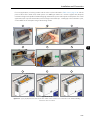
1
2
3
4
5
6
3
Figure 3.7 - Repositioning the mounting supports - frame sizes B, C and D
3-11
Installation and Connection
1
2
3
4
5
6
3
Figure 3.8 - Repositioning the mounting supports - frame size E
3.1.4 Installation of the Inverter Hoisting Eyes - Frame Size E
Two hoisting eyes for the inverter lifting, which are mounted at the inverter sides (rear part), are supplied. By
inverting their position, as shown in Figure 3.9 on page 3-12, two points for hoisting the inverter, which are
very useful during the mechanical installation of the inverter, are obtained.
Figure 3.9 - Installation of the inverter hoisting eyes frame size E
3-12
Installation and Connection
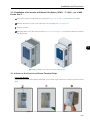
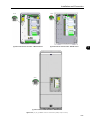
3.1.5 Installation of the Inverter with Nema1 Kit (Option, CFW11....T...ON1...) on a Wall Frame Size E
Fixing holes position and diameter according to the Figure 3.2 on page 3-4 for frame size E models.
External dimensions of the inverter with Nema1 kit according to 8.4 on page 8-16.
Fasten the inverter.
Install the Nema1 kit on the inverter as shown in Figure 3.10 on page 3-13 using the two M8 screws supplied
with the product.
3
Figure 3.10 - Installation of the Nema1 kit in frame size E model
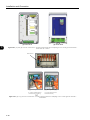
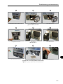
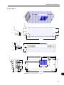
3.1.6 Access to the Control and Power Terminal Strips
Frame Size B and C:
It is necessary to remove the keypad and the front cover in order to get access to the control and power terminal
strips.
1
2
3
Figure 3.11 - Removal of keypad and front cover - frame size B and C
3-13
Installation and Connection
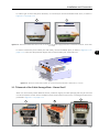
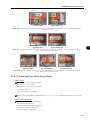
Frame Sizes D and E:
It is necessary to remove the keypad (HMI) and the control rack cover in order to get access to the control
terminal strip (see Figure 3.12 on page 3-14). In order to get access to the power terminal strip, remove the
bottom front cover (see Figure 3.13 on page 3-14).
1
3
2
3
Figure 3.12 - HMI and control rack cover removal - frame sizes D and E
1
2
Figure 3.13 - Bottom front cover removal - frame sizes D and E
Frame Sizes F, G and H:
In order to get access to the control terminals, it is necessary to remove the HMI and the control rack cover, as
showed in Figure 3.14 on page 3-14.
1
2
3
Figure 3.14 - Removal of the HMI and the control rack cover - frame sizes F, G and H
3-14
Installation and Connection
In order to get access to the power terminals, it is necessary to remove the bottom front cover, as shown in
Figure 3.15 on page 3-15.
1
2
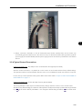
Figure 3.15 - Removal of the bottom front cover, to access to the power supply and motor connection terminals - frame sizes
F, G and H
In order to connect the power cables (line and motor), remove the bottom plate, as shown in Figure 3.16 on
page 3-15. In this case the protection degree of the inverter bottom part will be reduced.
Figure 3.16 - Removal of the bottom plate, to access the power terminals - frame sizes F, G and H
3.1.7 Removal of the Cable Passage Plate - Frame Size E
When it is not necessary neither IP20 nor Nema1 protection degree, the cable passage plate may be removed
in order to make the inverter electric installation easier. Remove the four M4 screws, according to the procedure
presented in Figure 3.17 on page 3-15.
3
1
2
Figure 3.17 - Removal of the cable passage plate - frame size E
3-15
3
Installation and Connection
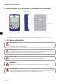
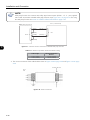
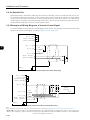
3.1.8 HMI Installation at the Cabinet Door or Command Panel (Remote HMI)
28.5 [1.12]
23.5 [0.93]
23.4 [0.92]
113.0 [4.45]
103.0 [4.06]
16.0 [0.63]
35.0 [1.38]
∅4.0 [0.16] (3X)
65.0 [2.56]
3
Figure 3.18 - Data for the HMI installation at the cabinet door or command panel – mm [in]
The keypad frame accessory can also be used to fix the HMI, as mentioned in Table 7.1 on page 7-3.
3.2 ELECTRICAL INSTALLATION
DANGER!
The following information is merely a guide for proper installation. Comply with applicable local
regulations for electrical installations.
DANGER!
Les informations suivantes constituent uniquement un guide pour une installation correcte. Respectez
les réglementations locales en vigueur pour les installations électriques.
DANGER!
Make sure the AC power supply is disconnected before starting the installation.
DANGER!
Vérifiez que l'alimentation secteur CA est débranchée avant de commencer l'installation.
ATTENTION!
Integral solid state short circuit protection does not provide branch circuit protection. Branch circuit
protection must be provided in accordance with applicable local codes.
3-16
Installation and Connection
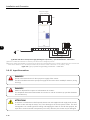
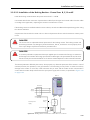
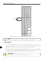
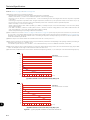
3.2.1 Identification of the Power and Grounding Terminals
R/L1, S/L2, T/L3: AC power supply connection.
U/T1, V/T2, W/T3: motor connection.
DC-: this is the negative potential terminal in the DC bus circuit.
BR: braking resistor connection (frame sizes B, C, D and E only).
DC+: this is the positive potential terminal in the DC bus circuit.
R/L1 S/L2T/L3
DC- BR DC+ U/T1 V/T2W/T3
3
Grounding
Figure 3.19 - Grounding and power terminals of frame size B and C models
R/L1 S/L2T/L3
DC- BRDC+
U/T1V/T2W/T3
Grounding
Figure 3.20 - Grounding and power terminals of frame size D models
3-17
Installation and Connection
3
Grounding
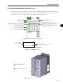
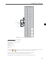
(4xM8, 4xM5)
Figure 3.21 - Grounding and power terminals of frame size E models
3-18
Installation and Connection
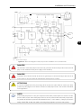
3
(a) Terminals for AC power supply and motor connection (terminals R/L1, S/L2 and T/L3 are not assembled in inverters with
special hardware DC)
DCDC+
(b) Terminals for DC power supply connection (only available in inverters with special hardware DC)
Figure 3.22 - (a) and (b) Grounding and power terminals of frame size F models
3-19
Installation and Connection
U/T1
V/T2
W/T3
R/L1
S/L2
T/L3
3
(a) Terminals for AC power supply and motor connection (terminals R/L1, S/L2 and T/L3 are not assembled in inverters with
special hardware DC)
DC-
DC+
(b) Terminals for DC power supply connection (only available in inverters with special hardware DC)
Figure 3.23 - (a) and (b) Grounding and power terminals of frame size G models
3-20
Installation and Connection
(a) Models 584 and 625 A
(b) Models 758 A and 804 A
DCDC+
3
(c) Frame size H
Figure 3.24 - (a) to (c) Grounding and power terminals of frame size H models
3-21
Installation and Connection
3.2.2 Power / Grounding Wiring and Fuses
ATTENTION!
Use proper cable lugs for the power and grounding connection cables.
ATTENTION!
Sensitive equipment such as PLCs, temperature controllers, and thermal couples shall be kept at a
minimum distance of 0.25 m (9.84 in) from the frequency inverter and from the cables that connect
the inverter to the motor.
DANGER!
Wrong cable connection:
- The inverter will be damaged if the power supply is connected to the output terminals (U/T1, V/T2,
or W/T3).
- Check all the connections before powering up the inverter.
- When replacing an existing inverter by a CFW-11, check if the installation and wiring is according
to the instructions listed in this manual.
3
DANGER!
Mauvaise connexion des câbles:
-Le variateur sera endommagé si l’alimentation d’entrée est connectée aux bornes de sortie (U/T1,
V/T2 ou W/T3).
-Vérifier toutes les connexions avant de mettre le variateur sous tension.
- En cas de remplacement d’un variateur existant par un CFW-11, vérifier si l’installation et le câblage
sont conformes aux instructions figurant dans ce manuel.
ATTENTION!
Residual Current Device (RCD):
- When installing an RCD to guard against electrical shock, only devices with a trip current of 300 mA
should be used on the supply side of the inverter.
- Depending on the installation (motor cable length, cable type, multimotor configuration, etc.), RCD
nuisance trips may occur. Contact the RCD manufacturer for selecting the most appropriate device
to be used with inverters.
NOTE!
The wire gauges listed in Table 3.2 on page 3-23 are orientative values. Installation conditions and
the maximum permitted voltage drop must be considered for the proper wiring sizing.
3-22
Installation and Connection
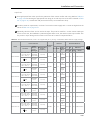
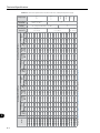
Input fuses:
Use High Speed Fuses at the input for the protection of the inverter rectifier and wiring. Refer to Table 3.2
on page 3-23 for selecting the appropriate fuse rating (I2t must be equal to or less than indicated in Table
3.2 on page 3-23, consider the cold (and not the fusion) current extinction value).
In order to meet UL requirements, use class J fuses at the inverter supply with a current not higher than the
values of Table 3.2 on page 3-23.
Optionally, slow blow fuses can be used at the input. They must be sized for 1.2 x the inverter rated input
current. In this case, the installation is protected against short-circuit, but not the inverter input rectifier. This
may result in major damage to the inverter in the event of an internal component failure.
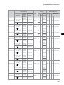
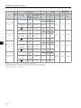
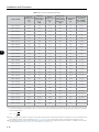
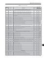
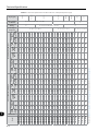
Table 3.2 - Recommended wire size / fuses – use copper wire (75 ºC (167 ºF)) – frame size B, 500 to 600 Vac supply voltage
Power Terminals
Model
Terminals
CFW110002T5
1.7 (15.0)
2.5
Ring
tongue
R/L1, S/L2, T/L3,
M4/Slotted
U/T1, V/T2, W/T3, and Phillips
DC+, DC- (1)
head (comb)
1.2 (10.8)
1.5
Pin
terminal
CFW110012T5
HD/ND
14
HD/ND
14
1.7 (15.0)
2.5
Ring
tongue
R/L1, S/L2, T/L3,
M4/Slotted
U/T1, V/T2, W/T3, and Phillips
DC+, DC- (1)
head (comb)
1.2 (10.8)
1.5
Pin
terminal
HD/ND
14
M4/Phillips
head
1.7 (15.0)
R/L1, S/L2, T/L3,
M4/Slotted
U/T1, V/T2, W/T3, and Phillips
DC+, DC- (1)
head (comb)
1.2 (10.8)
M4/Phillips
head
1.7 (15.0)
Ring
tongue
R/L1, S/L2, T/L3,
M4/Slotted
U/T1, V/T2, W/T3, and Phillips
DC+, DC- (1)
head (comb)
1.2 (10.8)
Pin
terminal
M4/Phillips
head
1.7 (15.0)
Ring
tongue
R/L1, S/L2, T/L3,
M4/Slotted
U/T1, V/T2, W/T3, and Phillips
DC+, DC- (1)
head (comb)
1.2 (10.8)
Pin
terminal
(PE)
CFW110017T5
Pin
terminal
1.5
M4/Phillips
head
(PE)
(PE)
M4/Phillips
head
1250 20
20
FNH00-20K-A
1250 20
20
FNH00-20K-A
1250 20
20
FNH00-20K-A
1250 20
20
FNH00-20K-A
1250 25
25
FNH00-25K-A
1250 40
40
FNH00-40K-A
Ring
tongue
2.5
Pin
terminal
HD/ND
HD/ND
HD/ND
1.7 (15.0)
Recommended Fuse
I²t
UL
WEG Fuse
Wire
mm2 AWG Terminal
Bype
[A²s] [A] In[A]
Model
M4/Phillips
head
(PE)
CFW110010T5
Overload
Class
1.2 (10.8)
(PE)
CFW110007T5
Recommended
Torque
N.m (lbf.in)
R/L1, S/L2, T/L3,
M4/Slotted
U/T1, V/T2, W/T3, and Phillips
DC+, DC- (1)
head (comb)
(PE)
CFW110004T5
Screw
Thread /
Screw
Head Type
Wire Size
2.5
2.5
4
14
12
10
Ring
tongue
3-23
3
Installation and Connection
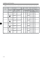
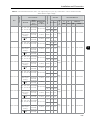
Table 3.3 - Recommended wire size / fuses – use copper wire (75 ºC (167 ºF)) – frame size C, 500 to 600 Vac supply voltage
Power Terminals
Model
Terminals
CFW110022T5
R/L1, S/L2, T/L3,
M5/Pozidriv
U/T1, V/T2, W/T3,
head
(1)
DC+, DC-
CFW110032T5
Pin
terminal
2.7 (24.0)
ND/HD
6
10
R/L1, S/L2, T/L3,
M5/Pozidriv
U/T1, V/T2, W/T3,
head
(1)
DC+, DC-
2.7 (24.0)
Pin
terminal
M5/Phillips
head
3.5 (31.0)
Ring
tongue
R/L1, S/L2, T/L3,
M5/Pozidriv
U/T1, V/T2, W/T3,
head
DC+, DC- (1)
2.7 (24.0)
Pin
terminal
ND/HD
ND/HD
10
10
8
8
M5/Phillips
head
3.5 (31.0)
Ring
tongue
R/L1, S/L2, T/L3,
M5/Pozidriv
U/T1, V/T2, W/T3,
head
(1)
DC+, DC-
2.7 (24.0)
Pin
terminal
(PE)
M5/Phillips
head
ND/HD
3.5 (31.0)
Recommended Fuse
I²t
UL
WEG Fuse
Wire
mm2 AWG Terminal
Bype
[A²s] [A] In[A]
Model
3.5 (31.0)
(PE)
CFW110044T5
Overload
Class
Ring
tongue
(PE)
3
Recommended
Torque
N.m (lbf.in)
M5/Phillips
head
(PE)
CFW110027T5
Screw
Thread /
Screw
Head Type
Wire Size
10
6
2100 40
40
FNH00-40K-A
2100 50
50
FNH00-50K-A
2100 60
63
FNH00-63K-A
2100 60
80
FNH00-80K-A
Ring
tongue
Note:
(1) There is a plastic cover in front of the DC- terminal at the frame size B inverters. It is necessary to break off that cover in order to get access to this terminal.
3-24
Installation and Connection
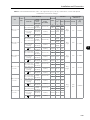
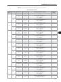
Table 3.4 - Recommended wire size / fuses – use copper wire (75 ºC (167 ºF)) – frame size D, 500 to 690 Vac supply voltage
Power Terminals
Model
Terminals
Wire Size
Screw
Recommended
Thread /
Torque
Screw
N.m (lbf.in)
Head Type
Overload
Class
I²t
UL
WEG Fuse
Wire
mm2 AWG Terminal
Type
[A²s] [A] In[A]
Model
M4/
R/L1, S/L2, T/L3,
Slotted and
U/T1, V/T2, W/T3,
Phillips head
DC+, DCCFW110002T6
(comb)
1.2 (10.8)
M5/Phillips
head
3.5 (31.0)
2.5
Ring
tongue
1.2 (10.8)
1.5
Pin
terminal
(PE)
R/L1, S/L2, T/L3, M4/ Slotted
U/T1, V/T2, W/T3, and Phillips
DC+, DC(comb)
CFW110004T6
M5/Phillips
(PE)
head
R/L1, S/L2, T/L3, M4/ Slotted
U/T1, V/T2, W/T3, and Phillips
DC+, DC(comb)
CFW110007T6
M5/Phillips
(PE)
head
CFW110010T6
R/L1, S/L2, T/L3, M4/ Slotted
U/T1, V/T2, W/T3, and Phillips
DC+, DC(comb)
14
3.5 (31.0)
2.5
Ring
tongue
1.2 (10.8)
1.5
Pin
terminal
HD/ND
14
2.5
HD/ND
2.5
14
Pin
terminal
HD/ND
2.5
12
3.5 (31.0)
Ring
tongue
1.2 (10.8)
Pin
terminal
HD/ND
4
10
3.5 (31.0)
Ring
tongue
1.2 (10.8)
Pin
terminal
HD/ND
6
10
M5/Phillips
head
3.5 (31.0)
Ring
tongue
R/L1, S/L2, T/L3, M4/ Slotted
U/T1, V/T2, W/T3, and Phillips
DC+, DC(comb)
1.2 (10.8)
Pin
terminal
(PE)
HD/ND
10
8
M5/Phillips
head
3.5 (31.0)
Ring
tongue
R/L1, S/L2, T/L3, M4/ Slotted
U/T1, V/T2, W/T3, and Phillips
DC+, DC(comb)
1.2 (10.8)
Pin
terminal
(PE)
HD/ND
10
8
M5/Phillips
head
3.5 (31.0)
Ring
tongue
R/L1, S/L2, T/L3, M4/ Slotted
U/T1, V/T2, W/T3, and Phillips
DC+, DC(comb)
1.2 (10.8)
Pin
terminal
(PE)
(PE)
M5/Phillips
head
HD/ND
3.5 (31.0)
20
FNH00-20K-A
7200 20
20
FNH00-20K-A
7200 20
20
FNH00-20K-A
7200 20
20
FNH00-20K-A
7200 25
25
FNH00-25K-A
7200 40
40
FNH00-40K-A
7200 50
50
FNH00-50K-A
7200 50
50
FNH00-50K-A
7200 60
63
FNH00-63K-A
7200 60
80
FNH00-80K-A
Pin
terminal
1.2 (10.8)
1.2 (10.8)
M5/Phillips
head
7200 20
Ring
tongue
R/L1, S/L2, T/L3, M4/ Slotted
U/T1, V/T2, W/T3, and Phillips
DC+, DC(comb)
R/L1, S/L2, T/L3, M4/ Slotted
U/T1, V/T2, W/T3, and Phillips
DC+, DC(comb)
CFW110022T6
CFW110044T6
HD/ND
3.5 (31.0)
R/L1, S/L2, T/L3, M4/ Slotted
U/T1, V/T2, W/T3, and Phillips
DC+, DC(comb)
CFW110017T6
M5/Phillips
(PE)
head
CFW110032T6
14
Ring
tongue
(PE)
CFW110027T6
HD/ND
Pin
terminal
M5/Phillips
head
(PE)
CFW110012T6
1.5
3.5 (31.0)
Recommended Fuse
10
6
Ring
tongue
3-25
3
Installation and Connection
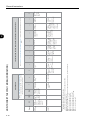
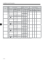
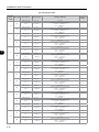
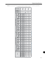
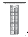
Table 3.5 - Recommended wire size / fuses – use copper wire (75 ºC (167 ºF)) – frame size E, 500 to 690 Vac supply voltage
Power Terminals
Model
Terminals
R/L1, S/L2, T/L3,
U/T1, V/T2, W/T3,
DC+, DCCFW110053T6
(PE)
R/L1, S/L2, T/L3,
U/T1, V/T2, W/T3,
DC+, DCCFW110063T6
3
(PE)
R/L1, S/L2, T/L3,
U/T1, V/T2, W/T3,
DC+, DCCFW110080T6
(PE)
R/L1, S/L2, T/L3,
U/T1, V/T2, W/T3,
DC+, DCCFW110107T6
(PE)
R/L1, S/L2, T/L3,
U/T1, V/T2, W/T3,
DC+, DCCFW110125T6
(PE)
R/L1, S/L2, T/L3,
U/T1, V/T2, W/T3,
DC+, DCCFW110150T6
(PE)
3-26
Wire Size
Screw
Recommended
Thread /
Torque
Screw
N.m (lbf.in)
Head Type
M8
(hexagonal
screw)
15 (132.75)
M5 and M8
(hexagonal
phillips
screw)
M5:
3.5 (31.0);
M8:
10 (88.5)
M8
(hexagonal
screw)
15 (132.75)
M5 and M8
(hexagonal
phillips
screw)
M5:
3.5 (31.0);
M8:
10 (88.5)
M8
(hexagonal
screw)
15 (132.75)
M5 and M8
(hexagonal
phillips
screw)
M5:
3.5 (31.0);
M8:
10 (88.5)
M8
(hexagonal
screw)
15 (132.75)
M5 and M8
(hexagonal
phillips
screw)
M5:
3.5 (31.0);
M8:
10 (88.5)
M8
(hexagonal
screw)
15 (132.75)
M5 and M8
(hexagonal
phillips
screw)
M5:
3.5 (31.0);
M8:
10 (88.5)
M8
(hexagonal
screw)
15 (132.75)
M5 and M8
(hexagonal
phillips
screw)
M5:
3.5 (31.0);
M8:
10 (88.5)
Overload
Class
Recommended Fuse
I²t
UL
WEG Fuse
mm2 AWG Terminals
[A²s]
HD
10
6
ND
25
4
HD/ND
25
4
HD
25
5
ND
35
2
HD/ND
25
4
HD
25
3
ND
35
2
HD/ND
25
4
HD
50
1
ND
50
1
HD/ND
35
2
HD
50
1
ND
50
1/0
HD/ND
35
2
HD
50
1/0
ND
70
2/0
HD/ND
50
1
[A] In[A]
Model
Ring
tongue
39200 100 100 FNH00-100K-A
Ring
tongue
39200 100 100 FNH00-100K-A
Ring
tongue
39200 125 125 FNH00-125K-A
Ring
tongue
39200 160 160 FNH00-160K-A
Ring
tongue
218000 200 200 FNH00-200K-A
Ring
tongue
218000 250 250 FNH00-250K-A
Installation and Connection
Terminals
Screw
Recommended
Thread /
Torque
Screw
N.m (lbf.in)
Head Type
R/L1, S/L2, T/L3, M12 (Phillips
U/T1, V/T2, W/T3 hex head)
CFW110170T6
DC+, DC- (use
them only for
braking)
(PE)
DC+, DC- (use
them only for
braking)
(PE)
DC+, DC- (use
them only for
braking)
(PE)
DC+, DC- (use
them only for
braking)
(PE)
M8 (Phillips
hex head)
10 (88.5)
HD/ND 50
1
DC+, DC- (use
them only for
braking)
(PE)
DC+, DC- (use
them only for
braking)
(PE)
120 4/0
(2x35) (2x2)
ND
150 300
(2x50) (2x1)
10 (88.5)
HD/ND 50
1/0
M8 (Phillips
hex head)
10 (88.5)
HD/ND 70
2/0
I²t
UL
WEG Fuse
[A²s]
[A]
In[A]
Model
Ring
320000
tongue
315
315
FNH1-315K-A
Ring
414000
tongue
400
400
FNH1-400K-A
HD
2x70 2x2/0
ND
2x70 2x2/0
Ring
414000
tongue
500
500
FNH2-500K-A
Ring
1051000
tongue
630
630
FNH2-630K-A
Ring
1445000
tongue
710
710
FNH2-630K-A
Ring
1445000
tongue
800
800
FNH3-800K-A
60 (531.00)
M8 (Phillips
hex head)
10 (88.5)
HD/ND 50
1/0
M8 (Phillips
hex head)
10 (88.5)
HD/ND 70
2/0
HD
2x70 2x2/0
ND
2x120 2x4/0
60 (531.00)
M8 (Phillips
hex head)
10 (88.5)
HD/ND 120
4/0
M8 (Phillips
hex head)
10 (88.5)
HD/ND 120
4/0
HD
2x120 2x4/0
ND
2x120 2x4/0
60 (531.00)
M8 (Phillips
hex head)
10 (88.5)
HD/ND 120
4/0
M8 (Phillips
hex head)
10 (88.5)
HD/ND 120
4/0
R/L1, S/L2, T/L3, M12 (Phillips
U/T1, V/T2, W/T3 hex head)
CFW110435T6
HD
M8 (Phillips
hex head)
R/L1, S/L2, T/L3, M12 (Phillips
U/T1, V/T2, W/T3 hex head)
CFW110365T6 G
120 4/0
(2x35) (2x2)
1/0
60 (531.00)
Recommended Fuse
2/0
HD/ND 50
R/L1, S/L2, T/L3, M12 (Phillips
U/T1, V/T2, W/T3 hex head)
CFW110315T6
70
10 (88.5)
R/L1, S/L2, T/L3, M12 (Phillips
U/T1, V/T2, W/T3 hex head)
CFW110289T6
ND
mm2 AWG
M8 (Phillips
hex head)
R/L1, S/L2, T/L3, M12 (Phillips
U/T1, V/T2, W/T3 hex head)
CFW110216T6 F
HD
60 (531.00)
Wire Size
Terminals
Power Terminals
Overload Class
Size
Frame Size
Table 3.6 - Recommended wire size / fuses – use copper wire (75 ºC (167 ºF)) – frame sizes F, G and H standard models,
500 to 690 Vac supply voltage
HD
2x120 2x4/0
ND
2x150 2x300
60 (531.00)
M8 (Phillips
hex head)
10 (88.5)
HD/ND 120
4/0
M8 (Phillips
hex head)
10 (88.5)
HD/ND 150
300
3-27
3
Terminals
ND
2x150 2x300
HD
2x120 2x250
60 (531.00)
M10 (Phillips
hex head)
30 (265.5)
ND/HD
M8 (Phillips
hex head)
10 (88.5)
ND/HD 150
DC+, DC(PE)
ND
4x70 4x2/0
HD
2x120 2x250
60 (531.00)
M10 (Phillips
hex head)
30 (265.5)
ND/HD
M8 (Phillips
hex head)
10 (88.5)
ND/HD 2x70 2x2/0
DC+, DC(PE)
ND
4x100 4x3/0
HD
4x70 4x1/0
M12
R/L1, S/L2, T/L3,
(Phillips hex
U/T1, V/T2, W/T3
head)
60 (531.00)
M10 (Phillips
hex head)
30 (265.5)
ND/HD
M8 (Phillips
hex head)
10 (88.5)
ND/HD 2x100 2x3/0
CFW110758T6
DC+, DC(PE)
ND
4x120 4x4/0
HD
4x100 4x3/0
M12
R/L1, S/L2, T/L3,
(Phillips hex
U/T1, V/T2, W/T3
head)
60 (531.00)
M10 (Phillips
hex head)
30 (265.5)
ND/HD
M8 (Phillips
hex head)
10 (88.5)
ND/HD 2x120 2x4/0
CFW110804T6
DC+, DC(PE)
Recommended Fuse
I²t
UL
[A²s]
[A]
In[A]
Model
Ring
1620000 1000(*) 1000(*) FNH3-1000K-A
tongue
Ring
1620000 2x630 2x630 FNH2-630K-A
tongue
Ring
1620000 2x710 2x710 FNH2-710K-A
tongue
Ring
1620000 2x800 2x800 FNH3-800K-A
tongue
Note:
(*) For this application, the fuse cannot be mounted on the FSW and RFW; only on the individual mounting base BNH.
3-28
WEG Fuse
300
M12
R/L1, S/L2, T/L3,
(Phillips hex
U/T1, V/T2, W/T3
head)
CFW110625T6
H
mm2 AWG
M12
R/L1, S/L2, T/L3,
(Phillips hex
U/T1, V/T2, W/T3
head)
CFW110584T6
3
Screw
Recommended
Thread /
Torque
Screw
N.m (lbf.in)
Head Type
Wire Size
Terminals
Power Terminals
Overload Class
Size
Frame Size
Installation and Connection
Installation and Connection
Table 3.7 - Recommended wire size / fuses – use copper wire (75 ºC (167 ºF)) – frame sizes F, G and H with Special
Hardware DC, fed from DC voltage
Power Terminals
Size
Frame
Size
CFW110170T6
O...DC...
CFW110216T6
O...DC...
F
CFW110289T6
O...DC...
CFW110315T6
O...DC...
CFW110365T6
O...DC...
CFW110435T6
O...DC...
G
Overload
Screw
Recommended
Class
Thread /
Terminals
Torque
mm2
Screw
N.m (lbf.in)
Head Type
HD
70
M12
R/L1, S/L2, T/L3,
(Phillips
60 (531.00)
120
U/T1, V/T2, W/T3
ND
hex head)
(2x35)
DC+, DC- (use
M8 (Phillips
120
them only for
10 (88.5)
HD/ND
hex head)
(2x35)
braking)
M8 (Phillips
10 (88.5)
HD/ND
50
(PE)
hex head)
120
HD
M12
(2x35)
R/L1, S/L2, T/L3,
(Phillips
60 (531.00)
U/T1, V/T2, W/T3
150
hex head)
ND
(2x50)
DC+, DC- (use
M8 (Phillips
150
them only for
10 (88.5)
HD/ND
hex head)
(2x50)
braking)
M8 (Phillips
10 (88.5)
HD/ND
70
(PE)
hex head)
M12
HD
2x70
R/L1, S/L2, T/L3,
(Phillips
60 (531.00)
U/T1, V/T2, W/T3
ND
2x70
hex head)
DC+, DC- (use
M8 (Phillips
them only for
10 (88.5)
HD/ND 2x70
hex head)
braking)
M8 (Phillips
10 (88.5)
HD/ND
70
(PE)
hex head)
M12
HD
2x70
R/L1, S/L2, T/L3,
(Phillips
60 (531.00)
U/T1, V/T2, W/T3
ND
2x120
hex head)
DC+, DC- (use
M8 (Phillips
them only for
10 (88.5)
HD/ND 2x120
hex head)
braking)
M8 (Phillips
10 (88.5)
HD/ND
120
(PE)
hex head)
M12
HD
2x120
R/L1, S/L2, T/L3,
(Phillips
60 (531.00)
U/T1, V/T2, W/T3
ND
2x120
hex head)
DC+, DC- (use
M8 (Phillips
them only for
10 (88.5)
HD/ND 2x120
hex head)
braking)
M8 (Phillips
10 (88.5)
HD/ND
120
(PE)
hex head)
M12
HD
2x120
R/L1, S/L2, T/L3,
(Phillips
60 (531.00)
U/T1, V/T2, W/T3
ND
2x150
hex head)
DC+, DC- (use
M8 (Phillips
them only for
10 (88.5)
HD/ND 2x150
hex head)
braking)
M8 (Phillips
10 (88.5)
HD/ND
150
(PE)
hex head)
Recommended
DC Fuses (1)
Wire Size
AWG Terminals Current
I 2t
[A²s]
2/0
4/0
(2x2)
4/0
(2x2)
Ring
tongue
315
320000
1
4/0
(2x2)
300
(2x1)
300
(2x1)
Ring
tongue
400
414000
3
2/0
2x2/0
2x2/0
2x2/0
Ring
tongue
500
414000
Ring
tongue
630
1051000
Ring
tongue
630
800
1445000
2/0
2x2/0
2x4/0
2x4/0
4/0
2x4/0
2x4/0
2x4/0
4/0
2x4/0
2x300
2x300
300
3-29
Installation and Connection
Power Terminals
Size
Frame
Size
Terminals
U/T1, V/T2, W/T3
CFW110584T6
O...DC...
DC+, DC- (use
them only for
braking)
(PE)
U/T1, V/T2, W/T3
CFW110625T6
O...DC...
DC+, DC- (use
them only for
braking)
H
3
(PE)
U/T1, V/T2, W/T3
CFW110758T6
O...DC...
DC+, DC- (use
them only for
braking)
(PE)
U/T1, V/T2, W/T3
CFW110804T6
O...DC...
DC+, DC- (use
them only for
braking)
(PE)
Overload
Screw
Recommended
Class
Thread /
Torque
mm2
Screw
N.m (lbf.in)
Head Type
M12
ND
2x150
(Phillips hex 60 (531.00)
HD
2x120
head)
M10
(Phillips hex
30 (265.5)
ND/HD
head)
M8 (Phillips
10 (88.5)
ND/HD
150
hex head)
M12
ND
4x70
(Phillips hex 60 (531.00)
HD
2x120
head)
M10
(Phillips hex
30 (265.5)
ND/HD
head)
M8 (Phillips
10 (88.5)
ND/HD 2x70
hex head)
M12
ND
4x100
(Phillips hex 60 (531.00)
HD
4x70
head)
M10
(Phillips hex
30 (265.5)
ND/HD
head)
M8 (Phillips
10 (88.5)
ND/HD 2x100
hex head)
M12
ND
4x120
(Phillips hex 60 (531.00)
HD
4x100
head)
M10
(Phillips hex
30 (265.5)
ND/HD
head)
M8 (Phillips
10 (88.5)
ND/HD 2x120
hex head)
Note:
(1) 2 fuses, one at + and other at – of supply cables is recommended.
These fuses combined must have interruption capacity for the following maximum DC voltage:
(a) 500 / 525 V (P0296 = 5); 550 / 575 V (P0296 = 6); 600 V (P0296 = 7): 1000 Vdc.
(b) 660 / 690 V (P0296 = 8): 1200 Vdc.
3-30
Recommended
DC Fuses (1)
Wire Size
AWG Terminals Current
I 2t
[A²s]
2x300
2x250
Ring
tongue
1086
1.620.000
Ring
tongue
1150
1.620.000
Ring
tongue
1306
1.620.000
Ring
tongue
1488
1.620.000
300
4x2/0
2x250
2x2/0
4x3/0
4x1/0
2x3/0
4x4/0
4x3/0
2x4/0
Installation and Connection
Table 3.8 - (a) and (b) Recommended cable lugs for power connections
(a) cable gauges in mm2
Wire Size
Stud Size
[mm2]
M5
10
M8
M5
25
M8
M5
35
M8
M12
M5
50
M8
M12
M5
70
M8
M12
M8
120
M12
150
M12
Manufacturer
Ring Lug, P/N
Crimping (Installation) Tool P/N
Hollingsworth
RM 10 -5
Tyco
710031-2
Hollingsworth
RM 10-8
Tyco
710031-6
Hollingsworth
RM 25 -5
Tyco
710026-1
Hollingsworth
RM 25-8
Tyco
710026-5
Hollingsworth
RM 35-5
Tyco
710027-1
Hollingsworth
RM 35-8
Tyco
710027-2
Hollingsworth
RM 35-12
Tyco
710036-4
Hollingsworth
RM 50-5
Tyco
710025-3
Hollingsworth
RM 50-8
Tyco
710025-2
Hollingsworth
RM 50-12
Tyco
710025-7
Hollingsworth
RM 70-5
Tyco
36921
Hollingsworth
RM 70-8
Tyco
710028-1
Hollingsworth
RM 70-12
Tyco
710028-5
Hollingsworth
RM 120-8
Tyco
709820-1
Hollingsworth
RM120-12
Tyco
709820-3
Hollingsworth
RM150-12
Tyco
709821-3
H 6.500
Manual Hydraulic Crimp Tooling
( TE p/n.: 1490749-1)
Die: 1583092-1
H 6.500
Manual Hydraulic Crimp Tooling
( TE p/n.: 1490749-1)
Die: 1583092-1
H 6.500
Manual Hydraulic Crimp Tooling
( TE p/n.: 1490749-1)
Die: 1583093-1
H 6.500
Manual Hydraulic Crimp Tooling
( TE p/n.: 1490749-1)
Die: 1583093-1
H 6.500
Manual Hydraulic Crimp Tooling
( TE p/n.: 1490749-1)
Die: 1583094-1
H 6.500
Manual Hydraulic Crimp Tooling
( TE p/n.: 1490749-1)
Die: 1583094-1
H 6.500
Manual Hydraulic Crimp Tooling
( TE p/n.: 1490749-1)
Die: 1583094-1
H 6.500
Manual Hydraulic Crimp Tooling
( TE p/n.: 1490749-1)
Die: 1583095-1
H 6.500
Manual Hydraulic Crimp Tooling
( TE p/n.: 1490749-1)
Die: 1583095-1
H 6.500
Manual Hydraulic Crimp Tooling
( TE p/n.: 1490749-1)
Die: 1583095-1
H 6.500
Manual Hydraulic Crimp Tooling
( TE p/n.: 1490749-1)
Die: 1583096-1
H 6.500
Manual Hydraulic Crimp Tooling
( TE p/n.: 1490749-1)
Die: 1583096-1
H 6.500
Manual Hydraulic Crimp Tooling
( TE p/n.: 1490749-1)
Die: 1583096-1
H 6.500
Manual Hydraulic Crimp Tooling
( TE p/n.: 1490749-1)
Die: 1583098-1
H 6.500
Manual Hydraulic Crimp Tooling
( TE p/n.: 1490749-1)
Die: 1583098-1
H 6.500
Manual Hydraulic Crimp Tooling
( TE p/n.: 1490749-1)
Die: 1752868-1 + 46751-2
Number of
Crimps
1
1
1
1
1
1
1
1
1
3
1
1
1
1
1
1
1
1
1
1
1
1
1
1
1
1
1
1
1
1
1
1
1
3-31
Installation and Connection
(b) cable gauges in AWG
Wire Size
[AWG/ Stud Size
kcmil]
M5
6
M8
M5
5
M8
M5
3
4
M8
M5
3
M8
M5
2
M8
M12
M5
1
M8
M12
M5
1/0
M8
3-32
Manufacturer
Ring Lug, P/N
Crimping Tool P/N
Hollingsworth
R 410
Tyco
710030-1
Hollingsworth
R 4516
Tyco
710030-5
Hollingsworth
R 410
Tyco
710030-1
Hollingsworth
R 4516
Tyco
710030-5
Hollingsworth
R 410
Tyco
710026-1
Hollingsworth
R 4516
Tyco
710026-5
Hollingsworth
R 410
Tyco
710026-1
Hollingsworth
R 4516
Tyco
710026-5
Hollingsworth
R 210
Tyco
710027-1
Hollingsworth
R 2516
Tyco
710027-2
Hollingsworth
R 2516
Tyco
710036-4
Hollingsworth
R 110
Tyco
710027-1
Hollingsworth
R 1516
Tyco
710027-2
Hollingsworth
R 138
Tyco
710036-4
Hollingsworth
R 10516
Tyco
710025-3
Hollingsworth
R 10516
Tyco
710025-2
H 6.500
Manual Hydraulic Crimp Tooling
( TE p/n.: 1490749-1)
Die: 1583092-1
H 6.500
Manual Hydraulic Crimp Tooling
( TE p/n.: 1490749-1)
Die: 1583092-1
H 6.500
Manual Hydraulic Crimp Tooling
( TE p/n.: 1490749-1)
Die: 1583092-1
H 6.500
Manual Hydraulic Crimp Tooling
( TE p/n.: 1490749-1)
Die: 1583092-1
H 6.500
Manual Hydraulic Crimp Tooling
( TE p/n.: 1490749-1)
Die: 1583093-1
H 6.500
Manual Hydraulic Crimp Tooling
( TE p/n.: 1490749-1)
Die: 1583093-1
H 6.500
Manual Hydraulic Crimp Tooling
( TE p/n.: 1490749-1)
Die: 1583093-1
H 6.500
Manual Hydraulic Crimp Tooling
( TE p/n.: 1490749-1)
Die: 1583093-1
H 6.500
Manual Hydraulic Crimp Tooling
( TE p/n.: 1490749-1)
Die: 1583094-1
H 6.500
Manual Hydraulic Crimp Tooling
( TE p/n.: 1490749-1)
Die: 1583094-1
H 6.500
Manual Hydraulic Crimp Tooling
( TE p/n.: 1490749-1)
Die: 1583094-1
H 6.500
Manual Hydraulic Crimp Tooling
( TE p/n.: 1490749-1)
Die: 1583094-1
H 6.500
Manual Hydraulic Crimp Tooling
( TE p/n.: 1490749-1)
Die: 1583094-1
H 6.500
Manual Hydraulic Crimp Tooling
( TE p/n.: 1490749-1)
Die: 1583094-1
H 6.500
Manual Hydraulic Crimp Tooling
( TE p/n.: 1490749-1)
Die: 1583095-1
H 6.500
Manual Hydraulic Crimp Tooling
( TE p/n.: 1490749-1)
Die: 1583095-1
Number of
Crimps
1
1
1
1
1
1
1
1
1
1
1
1
1
1
1
1
1
1
1
1
1
1
1
1
1
1
1
1
1
1
1
1
Installation and Connection
Wire Size
[AWG/ Stud Size
kcmil]
Ring Lug, P/N
Crimping Tool P/N
Hollingsworth
R 110
Tyco
------
Hollingsworth
R 1516
Tyco
710028-1
Hollingsworth
R 138
Tyco
710028-5
Hollingsworth
R 2038
Tyco
709820-1
Hollingsworth
R 4038
Tyco
709820-3
Hollingsworth
R 4038
Tyco
709821-3
H 6.500
Manual Hydraulic Crimp Tooling
( TE p/n.: 1490749-1)
Die: 1583096-1
H 6.500
Manual Hydraulic Crimp Tooling
( TE p/n.: 1490749-1)
Die: 1583096-1
H 6.500
Manual Hydraulic Crimp Tooling
( TE p/n.: 1490749-1)
Die: 1583096-1
H 6.500
Manual Hydraulic Crimp Tooling
( TE p/n.: 1490749-1)
Die: 1583098-1
H 6.500
Manual Hydraulic Crimp Tooling
( TE p/n.: 1490749-1)
Die: 1583098-1
H 6.500
Manual Hydraulic Crimp Tooling
( TE p/n.: 1490749-1)
Die: 1752868-1 + 46751-2
M5
2/0
M8
M12
M8
4/0
M12
300
Number of
Crimps
Manufacturer
M12
1
1
1
1
1
1
1
1
1
1
1
3
1
3.2.3 Power Connections
PE
PE
R
S
T
U
V
W PE
PE
W
V
U
R
S
T
Power
supply
Disconnect
switch
Fuses
Shielding
Figure 3.25 - Power and grounding connections - frame sizes B, C, D and E
3-33
Installation and Connection
Accessory
DC+
DC-
DC-
DC+
External
braking
module
Braking
resistor
DC+
BR
R
PE
3
S
T
U
V
W
PE
W
V
U
R
S
T
AC power
supply
Disconnect
switch
Shielding
Fuses
(a) Models with AC power supply (IP20 degree of protection) - frame sizes F and G
DC power supply:
574 to 1025 Vdc
Fuses
DC-
DC+
U
V
W
PE
W
V
U
PE
Shielding
(b) Models with direct current power supply (IP00 degree of protection) - special hardware DC - frame sizes F and G
Figure 3.26 - (a) to (b) Power and grounding connections - frame sizes F and G
3-34
Installation and Connection
Accessory
DC+
DC-
DC-
DC+
External
braking
module
Braking
resistor
DC+
BR
R
PE
S
T
U
V
W
PE
W
V
U
3
R
S
T
AC power
supply
Fuses
Disconnect
switch
Shielding
Line reactor (1)
(a) Models with AC power supply (IP20 degree of protection) - frame size H (models 584 A and 625 A)
Accessory
DC+
DC-
DC-
DC+
External
braking
module
Braking
resistor
DC+
BR
R1
PE
R2
S1
S2 T1
T2 U
V
W
PE
W
V
U
R
S
T
AC power
supply
Disconnect
switch
Fuses
Line reactor (2)
Fuses
Line reactor (2)
Shielding
(b) Models with AC power supply (IP20 degree of protection - frame size H (models 758 A and 804 A)
3-35
Installation and Connection
DC power supply:
574 to 1025 Vdc
Fuses
DC-
3
R1
R2
S1
DC+
S2 T1
T2 U
V
W
PE
W
V
U
PE
Shielding
(c) Models with direct current power supply (IP00 degree of protection) - special hardware DC - frame size H
(1) For frame H models 584 A and 625 A it's necessary a line reactor with 3 % voltage drop minimum.
(2) For frame H models 758 A and 804 A it's necessary two line reactors with 3 % voltage drop minimum. Consider a half of inverter input current for each
reactor and an unbalance of 15 %. For example in model 758 A, the maximum current in each reactor is 1.15 (758/2) = 436 A).
Figure 3.27 - (a) to (c) Power and grounding connections - frame size H
3.2.3.1 Input Connections
DANGER!
Provide a disconnect device for the input power supply of the inverter.
This device shall disconnect the input power supply for the inverter when needed (for instance, during
servicing).
DANGER!
Montez un dispositif de coupure sur l'alimentation du variateur.
Ce composant déconnecte l'alimentation du variateur si cela est nécessaire (ex. pendant l'entretien
et la maintenance).
ATTENTION!
A contactor or another device that frequently disconnects and reapplies the AC supply to the inverter,
in order to start and stop the motor, may cause damage to the inverter power section. The drive
is designed to use control signals for starting and stopping the motor. If used for that purpose, the
input device must not exceed one operation per minute; otherwise, the inverter may be damaged.
3-36
Installation and Connection
ATTENTION!
The power supply that feeds the inverter shall have a grounded neutral. In case of IT networks, follow
the instructions described in item 3.2.3.1.1 IT Networks on page 3-37.
NOTE!
The input power supply voltage shall be compatible with the inverter rated voltage.
NOTE!
Power factor correction capacitors are not needed at the inverter input (R, S, T) and shall not be
installed at the output of the inverter (U, V, W).
AC power supply considerations
Suitable for use on a circuit capable of delivering not more than 100.000 Arms symmetrical Ampères at 690 V
maximum, when protected by Class J fuses or special purpose fuses.
3.2.3.1.1 IT Networks
ATTENTION!
For using the inverter CFW11...T5 or T6 in IT networks (neutral conductor not grounded or grounded
via high ohmic value resistor) or in corner-grounded delta networks, the following modifications are
required in the connections of some internal components to ground:
Frame size B, C and D: remove the screw as indicated in Figure 3.28 on page 3-38.
Frame size E models: change the position of the J1 jumper on the PRT board from
(XE1) to
“NC” (XIT), according to Figure 3.29 on page 3-38.
Frame size F, G and H models: disconnect the cable with the ring tongue lug from the ground busbar
and connect it to the isolated point on the power terminal block as shown in the Figure 3.30 on page
3-39, Figure 3.31 on page 3-39 and Figure 3.32 on page 3-39 .
That is necessary to avoid damage to the inverter when operating with a line input shorted to ground.
NOTE!
The ground-fault protection (F074) is intended for IGBT protection and may not be activated when
inverter output is shorted to ground, when fed by IT networks.
External insulation monitoring devices should be used for system fault monitoring.
3-37
3
Installation and Connection
(a) Frame size B
3
(b) Frame size D
Figure 3.28 - (a) and (b) Ground connections – location and procedure for adapting to IT or corner-ground networks –
frame sizes B, C and D
PRT3 board
(a) Location of board
(b) Initial position
(c) Final position (IT)
(J1 jumper of PRT3 board
(XE1))
connected to
(J1 jumper of the board
connected to NC)
Figure 3.29 - (a) to (c) Ground connections - location and procedure for adapting to IT or corner-ground networks frame size E
3-38
Installation and Connection
Remove
(a) Initial position
Connect
(b) Final position (IT)
Figure 3.30 - (a) and (b) Ground connections - location and procedure for adapting to IT or corner-ground networks frame sizes F and G
Remove
(a) Initial position
Connect
(b) Final position (IT)
Figure 3.31 - (a) and (b) Ground connections - location and procedure for adapting to IT or corner-ground networks frame sizes H models 584 A and 625 A
Remove
(a) Initial position
Connect
(b) Final position (IT)
Connect
(c) Final position (IT)
Figure 3.32 - (a) to (c) Ground connections - location and procedure for adapting to IT or corner-ground networks frame sizes H models 784 A and 804 A
3.2.3.1.2 Command Fuses of Pre-charge Circuit
Frame size E:
Specifications of the used auxiliary fuse:
Slow blow fuse 1 A / 1000 V.
Manufacturer: Ferraz Shawmut/ Mersen.
Part number: DTC1-2.
WEG part number: 11123302.
Auxiliary fuse is assembled in PRT3 board. Figure 3.29 on page 3-38 shows its location on the inverter.
Frame sizes F, G and H:
Specifications of the used auxiliary fuse:
4 A / 690 V slow blow fuse.
Manufacturer: Ferraz Shawmut / Mersen.
Commercial reference: 17019-G.
WEG part number: 10411503.
3-39
3
Installation and Connection
3.2.3.2 Dynamic Braking
NOTE!
All frame size B and C models do have internal braking IGBT. Models of frame sizes D and E with
the codification CFW11...O...NB... and all models of frame sizes F, G and H do not have internal
braking IGBT.
NOTE!
For dynamic braking with frame sizes F, G and H models use external braking module (e.g. DBW03).
For installation refer to Figure 3.33 on page 3-41.
The braking torque that can be obtained from the frequency inverter without braking resistors varies from 10 %
to 35 % of the motor rated torque.
Braking resistors shall be used to obtain higher braking torques. In this case, the energy regenerated in excess
is dissipated in a resistor mounted externally to the inverter.
3
This type of braking is used in cases where short deceleration times are desired or when high inertia loads are
driven.
The “Optimal Braking” feature may be used with the vector control mode, which eliminates in most cases the
need of an external braking resistor.
NOTE!
Set P0151 and P0185 to their maximum values (1000 V for power supply voltages from 500 to 600 V;
1200 V for power supply voltage from 660 to 690 V) when using dynamic braking.
3.2.3.2.1 Sizing the Braking Resistor
The following application data shall be considered for the adequate sizing of the braking resistor:
- Desired deceleration time.
- Load inertia.
- Braking duty cycle.
In any case, the effective current value and the maximum braking current value presented in Table 3.8 on page
3-31 shall be respected.
The maximum braking current defines the minimum braking resistor value in ohms.
The DC bus voltage level for the activation of the dynamic braking function is defined by parameter P0153
(dynamic braking level).
The power of the braking resistor is a function of the deceleration time, the load inertia, and the load torque.
3-40
Installation and Connection
For most applications, a braking resistor with the value in ohms indicated in Table 3.9 on page 3-42 and the
power of 20 % of the rated driven motor power. Use WIRE type resistors in a ceramic support with adequate
insulation voltage and capable of withstanding high instantaneous power with respect to rated power. For critical
applications with very short deceleration times and high inertia loads (ex.: centrifuges) or short duration cycles,
consult WEG for the adequate sizing of the braking resistor.
1
2
3
4
5
6
3
(a) Frame size F and G
1
2
3
Remove Cover
(b) Frame size H
Figure 3.33 - (a) to (b) Sequence for the connection cables of DC+ and DC- for connection of an external braking
module to CFW-11 inverter
3-41
Installation and Connection
Table 3.9 - Dynamic braking specifications
Inverter Model
3
Maximum
Braking Power
Maximum
Effective
Braking Power
(mean value)
Braking Current
Braking Current
(peak value)
in the Braking
(1)
(Imax)
(I
)
effective
(Pmax) (2)
Resistor (PR) (2)
[A]
[A]
[kW]
[kW]
Recommended
Resistor
[W]
Power Wire Size
(terminals
DC+ and BR) (3)
[mm2 (AWG)]
CFW110002T5
36.4
43.6
31.9
33.5
33
6(8)
CFW110004T5
36.4
43.6
31.9
33.5
33
6(8)
CFW110007T5
36.4
43.6
31.9
33.5
33
6(8)
CFW110010T5
36.4
43.6
31.9
33.5
33
6(8)
CFW110012T5
36.4
43.6
31.9
33.5
33
6(8)
CFW110017T5
36.4
43.6
31.9
33.5
33
6(8)
CFW110022T5
45.5
42.7
31.7
15.1
22
10 (8)
CFW110027T5
45.5
42.7
31.7
15.1
22
10 (8)
CFW110032T5
45.5
42.7
31.7
15.1
22
10 (8)
CFW110044T5
45.5
42.7
31.7
15.1
22
10 (8)
CFW110002T6
45.5
54.5
45.5
54.5
26.4
10 ( 6 )
CFW110004T6
45.5
54.5
45.5
54.5
26.4
10 ( 6 )
CFW110007T6
45.5
54.5
45.5
54.5
26.4
10 ( 6 )
CFW110010T6
45.5
54.5
45.5
54.5
26.4
10 ( 6 )
CFW110012T6
45.5
54.5
45.5
54.5
26.4
10 ( 6 )
CFW110017T6
45.5
54.5
45.5
54.5
26.4
10 ( 6 )
CFW110022T6
45.5
54.5
45.5
54.5
26.4
10 ( 6 )
CFW110027T6
45.5
54.5
45.5
54.5
26.4
10 ( 6 )
CFW110032T6
45.5
54.5
45.5
54.5
26.4
10 ( 6 )
CFW110044T6
45.5
54.5
45.5
54.5
26.4
10 ( 6 )
CFW110053T6
181.8
218.2
152.0
152.5
6.6
95 ( 3/0 )
CFW110063T6
181.8
218.2
152.0
152.5
6.6
95 ( 3/0 )
CFW110080T6
181.8
218.2
152.0
152.5
6.6
95 ( 3/0 )
CFW110107T6
181.8
218.2
152.0
152.5
6.6
95 ( 3/0 )
CFW110125T6
272.7
327.3
152.0
101.7
4.4
2 x 50 ( 2 x 1/0 )
CFW110150T6
272.7
327.3
152.0
101.7
4.4
2 x 50 ( 2 x 1/0 )
(1) The effective braking current presented is just an indicative value, because it depends on the braking duty cycle. The effective braking current
can be obtained from the equation below, where tbr is given in minutes and corresponds to the sum of all braking times during the most severe
cycle of 5 (five) minutes.
Ieffective = Imax x
tbr
5
(2) The Pmax and PR values (maximum and mean power of the braking resistor respectively) presented are valid for the recommended resistors and
for the effective braking currents presented in Table 3.9 on page 3-42. The resistor power change according to the braking duty cycle.
(3) For specifications on the recommended terminal type for the connection of the braking resistor (terminals DC+ and BR), refer to the DC+
terminal specification on Table 3.4 on page 3-25 to Table 3.7 on page 3-29.
3-42
Installation and Connection
3.2.3.2.2 Installation of the Braking Resistor - Frame Sizes B, C, D and E
Install the braking resistor between the power terminals DC+ and BR.
Use twisted cable for the connection. Separate these cables from the signal and control cables. Size the cables
according to the application, respecting the maximum and effective currents.
If the braking resistor is installed inside the inverter cabinet, consider its additional dissipated energy when sizing
the cabinet ventilation.
Set parameter P0154 with the resistor value in ohms and parameter P0155 with the maximum resistor power
in kW.
DANGER!
The inverter has an adjustable thermal protection for the braking resistor. The braking resistor and
the braking transistor may damage if parameters P0153, P0154, and P0155 are not properly set or
if the input voltage surpasses the maximum permitted value.
DANGER!
Le variateur possède une protection thermique réglable pour la résistance de freinage. La résistance
de freinage et le transistor de freinage peuvent être endommagés si les paramètres P0153, P0154 et
P0155 ne sont pas correctement définis ou si la tension d’entrée dépasse la valeur maximale autorisée.
The thermal protection offered by the inverter, when properly set, allows the protection of the resistor in case of
overload; however, this protection is not guaranteed in case of braking circuitry failure. In order to avoid any
damage to the resistor or risk of fire, install a thermal relay in series with the resistor and/or a thermostat in
contact with the resistor body to disconnect the input power supply of the inverter, as presented in Figure 3.34
on page 3-43.
CFW-11
Contactor
R
S
T
Power
supply
BR
Control power
supply
DC+
Thermal
relay
Thermostat
Braking
resistor
Figure 3.34 - Braking resistor connection - frame sizes B, C, D and E
3-43
3
Installation and Connection
NOTE!
DC current flows through the thermal relay bimetal strip during braking.
3.2.3.3 Output Connections
ATTENTION!
The inverter has an electronic motor overload protection that shall be adjusted according to the
driven motor. When several motors are connected to the same inverter, install individual overload
relays for each motor.
ATTENTION!
The motor overload protection available in the CFW-11 is in accordance with the IEC60947-4-2
and UL508C standards. Note the following information:
Trip current equal to 1.25 times the motor rated current (P0401) adjusted in the oriented start-up
menu.
The maximum value for P0398 (Motor service factor) is 1.15.
Parameters P0156, P0157 and P0158 (Overload current at 100 %, 50 % and 5 % of the rated
speed, respectively) are automatically adjusted when parameters P0401 (Motor rated current)
and/or P0406 (Motor ventilation) are adjusted in the oriented start-up routine. If parameters
P0156, P0157 and P0158 are manually adjusted, the maximum allowed value is 1.05 x P0401.
3
ATTENTION!
If a disconnect switch or a contactor is installed between the inverter and the motor, never operate
them with a spinning motor or with voltage at the inverter output.
The characteristics of the cable used for the inverter and motor interconnection, as well as the physical location
are extremely important to avoid electromagnetic interference in other equipment and to not affect the life cycle
of motor windings and motor bearings controlled by inverters.
Recommendations for the motor cables:
Unshielded Cables:
Can be used when it is not necessary to meet the European directive of electromagnetic compatibility
(89/336/EEC).
Keep motor cables away from other cables (signal cables, sensor cables, control cables, etc.), according to
Table 3.10 on page 3-45.
The emission of the cables may be reduced by installing them inside a metal conduit, which shall be grounded
at both ends.
Connect a fourth cable between the motor ground and the inverter ground.
NOTE!
The magnetic field created by the current circulation in these cables may induce current in close metal
pieces, heat them, and cause additional electrical losses. Therefore, keep the three cables (U, V, W)
always together.
3-44
Installation and Connection
Shielded Cables:
They are mandatory when the electromagnetic compatibility directive (89/336/EEC) shall be met, as defined
by the standard EN 61800-3 “Adjustable Speed Electrical Power Drive Systems”. These cables act mainly
by reducing the irradiated emission in the radio-frequency range.
In reference to the type and details of installation, follow the recommendations of IEC 60034-25 “Guide for
Design and Performance of Cage Induction Motors Specifically Designed for Converter Supply” – refer to a
summary in Figure 3.35 on page 3-45. Refer to the standard for further details and eventual modifications
related to new revisions.
Keep motor cables away from other cables (signal cables, sensor cables, control cables, etc.), according to
Table 3.10 on page 3-45.
The grounding system shall be well interconnected among the several installation locations such as the
grounding points of the motor and the inverter. Voltage difference or impedance between the several points
may cause the circulation of leakage currents among the equipment connected to the ground, resulting in
electromagnetic interference problems.
Table 3.10 - Minimum separation distance between motor cables and all other cables
Cable Length
≤ 30 m (100 ft)
> 30 m (100 ft)
Minimum Separation Distance
≥ 10 cm (3.94 in)
≥ 25 cm (9.84 in)
ooooooooo
o
oo
U
W
PE
V
U
W
V
ooo ooooo
oo
PE
oooooooooo
oo
oooooooo
oo
PE
PEs
SCu
AFe
(a) Symmetrical shielded cables: three concentric conductors with or without a ground conductor, symmetrically
manufactured, with an external shield of copper or aluminum.
W
V
U
PE
SCu
(b) Alternatives for conductors up to 10 mm2
Notes:
(1) SCu = copper or aluminum external shielding.
(2) AFe = steel or galvanized iron.
(3) PE = ground conductor.
(4) Cable shielding shall be grounded at both ends (inverter and motor). Use 360º connections for a low impedance to high-frequencies.
(5) For using the shield as a protective ground, it shall have at least 50 % of the power cables conductivity. Otherwise, add an external ground conductor
and use the shield as an EMC protection.
(6) Shielding conductivity at high-frequencies shall be at least 10 % of the power cables conductivity.
Figure 3.35 - (a) and (b) Motor connection cables recommended by IEC 60034-25
3-45
3
Installation and Connection
Connection of the motor cable shield to ground:
Connection of the motor cable shield to ground: make a connection with low impedance for high frequencies.
Frame size B and C:
There is a kit for connection of the shielding of power cables that is supplied with the inverters (except for inverters
CFW11...T5O...NF...), which assembled on the bottom of the enclosure as shown in Figure 3.36 on page 3-46
and facilitates the connection of the shielding of motor and the line cable. That kit is also an acessory - PCSB-01.
3
Figure 3.36 - Detail of the motor cable shield connection with the power cables shielding kit (PCSB-01) provided with
inverters of frame size B and C
For frame sizes D and E, there is a provision for grounding the motor cable shield in the standard inverter
enclosure.
3.2.4 Grounding Connections
DANGER!
Do not share the grounding wiring with other equipment that operate with high currents (e.g. high
power motors, soldering machines, etc.). When installing several inverters, follow the procedures
presented in Figure 3.37 on page 3-47 for the grounding connection.
DANGER!
Ne pas partager le câblage de mise à la terre avec d’autres équipements opérant avec des intensités
élevées (par ex: moteurs haute puissance, postes de soudure, etc.). Lors de l’installation de plusieurs
variateurs, appliquer les procédures présentées dans l’illustration Figure 3.37 à la page 3-47 pour
la connexion de mise à la terre.
ATTENTION!
The neutral conductor of the network must be solidly grounded; however, this conductor must not
be used to ground the inverter.
3-46
Installation and Connection
DANGER!
The inverter must be obligatorily connected to a protective ground (PE).
Observe the following:
- Use a minimum wire gauge for ground connection equal to the indicated in Table 3.2 on page
3-23 to Table 3.6 on page 3-27. Conform to local regulations and/or electrical codes in case a
different wire gauge is required.
- Connect the inverter grounding connections to a ground bus bar, to a single ground point, or to a
common grounding point (impedance ≤ 10 Ω).
- To comply with IEC 61800-5-1 standard, connect the inverter to the ground by using a single
conductor copper cable with a minimum wire gauge of 10 mm2, since the leakage current is greater
than 3.5 mAac.
DANGER!
Le variateur doit être raccordé à une terre de protection (PE).
Observer les règles suivantes:
- Utilisez la section minimale de raccordement à la terre indiquée dans les Table 3.2 à la page
3-23 à Table 3.6 à la page 3-27. Se conformer aux à la règlementation locale et/ou aux codes
de l'électricité si une autre épaisseur de fil est nécessaire.
- Connectez la masse du variateur à une barre collectrice de terre en un seul point ou à un point
commun de raccordement à la terre (impédance ≤ 10 Ω).
- Pour assurer la conformité avec la norme CEI 61800-5-1, connecter le variateur à la terre grâce
à un câble en cuivre à un conducteur ayant une épaisseur de fil minimale de 10 mm², étant donné
que le courant de fuite est supérieur à 3,5 mA C.A.
CFW-11 nº1
CFW-11 nº2
CFW-11 nºN
CFW-11 nº1
CFW-11 nº2
Cabinet internal ground busbar
Figure 3.37 - Grounding connections with multiple inverters
3.2.5 Control Connections
The control connections (analog inputs/outputs, digital inputs/outputs), must be made at the CC11 control
board terminal strip XC1.
Functions and typical connections are presented in Figure 3.38 on page 3-49.
3-47
3
Installation and Connection
CW
≥5 kΩ
CCW
rpm
XC1
Terminal Strip
1
REF+
2
AI1+
3
AI1-
4
REF-
5
AI2+
6
AI2-
7
8
3
amp
9
AO1
Factory Setting Function
Positive reference for
potentiometer.
Output voltage: +5.4 V, ±5 %.
Maximum output current: 2 mA.
Analog input # 1:
Speed reference (remote).
Differential
Resolution: 12 bits.
Signal: 0 to 10 V (RIN = 400 kΩ) / 0 to 20 mA / 4 to 20 mA (RIN = 500 Ω).
Maximum voltage: ±30 V.
Negative reference for
potentiometer.
Output voltage: -4.7 V, ±5 %.
Maximum output current: 2 mA.
Analog input # 2:
No function.
Differential
Resolution: 11 bits + signal.
Signal: 0 to ±10 V (RIN = 400 kΩ) / 0 to 20 mA / 4 to 20 mA (RIN = 500 Ω).
Maximum voltage: ±30 V.
Analog output # 1:
Speed.
Galvanic Isolation
Resolution: 11 bits.
Signal: 0 to 10 V (RL ≥ 10 kΩ) / 0 to 20 mA / 4 to 20 mA (RL ≤ 500 Ω).
Protected against short-circuit.
AGND Reference (0 V) for the
(24 V) analog outputs.
AO2
Specifications
Analog output # 2:
Motor current.
10
AGND Reference (0 V) for the
(24 V) analog outputs.
11
DGND*
12
COM
Reference (0 V) for the 24
Vdc power supply.
Connected to the ground (frame) through an impedance: 940 Ω resistor
in parallel with a 22 nF capacitor.
Galvanic Isolation
Resolution: 11 bits.
Signal: 0 to 10 V (RL ≥ 10 kΩ) / 0 to 20 mA / 4 to 20 mA (RL ≤ 500 Ω).
Protected against short-circuit.
Connected to the ground (frame) through an impedance: 940 Ω resistor
in parallel with a 22 nF capacitor.
Connected to the ground (frame) through an impedance: 940 Ω resistor
in parallel with a 22 nF capacitor.
Common point of the digital
inputs.
24 Vdc power supply.
13
24 Vdc
14
COM
15
DI1
16
DI2
17
DI3
18
DI4
Digital input # 4:
No function.
19
DI5
Digital input # 5:
Jog (remote).
20
DI6
Digital input # 6:
2nd ramp.
21
22
23
24
25
26
27
28
29
NC1
C1
NO1
NC2
C2
NO2
NC3
C3
NO3
24 Vdc power supply, ±8 %.
Capacity: 500 mA.
Note: In the models with the 24 Vdc external control power supply
(CFW11...O...W...) the terminal 13 of XC1 becomes an input, i.e., the user
must connect a 24 Vdc power supply for the inverter (refer to the item 7.1.3
24 Vdc External Control Power Supply on page 7-1, for more details). In
all the other models this terminal is an output, i.e., the user has a 24 Vdc
power supply available there.
Common point of the digital
inputs.
Digital input # 1:
Start / Stop.
6 isolated digital inputs
High level ≥ 18 V.
Low level ≤ 3 V.
Digital input # 2:
Direction of rotation (remote). Maximum input voltage = 30 V.
Input current: 11 mA @ 24 Vdc.
Digital input # 3:
No function.
Digital output #1 DO1
(RL1): No fault.
Contact rating:
Maximum voltage: 240 Vac.
Maximum current: 1 A.
NC - Normally closed contact.
Digital output #2 DO2 (RL2): C - Common.
N > NX - Speed > P0288.
NO - Normally open contact.
Digital output #3 DO3 (RL3):
N* > NX - Speed reference
> P0288.
(a) - Digital inputs working as "Active High"
3-48
Installation and Connection
CW
≥5 kΩ
CCW
rpm
XC1
Terminal Strip
Specifications
1
REF+
Positive reference for
potentiometer.
Output voltage: +5.4 V, ±5 %.
Maximum output current: 2 mA.
2
AI1+
Analog input # 1:
Speed reference (remote).
3
AI1-
Differential
Resolution: 12 bits.
Signal: 0 to 10 V (RIN = 400 kΩ) / 0 to 20 mA / 4 to 20 mA (RIN = 500 Ω).
Maximum voltage: ±30 V.
4
REF-
Negative reference for
potentiometer.
Output voltage: -4.7 V, ±5 %.
Maximum output current: 2 mA.
5
AI2+
Analog input # 2:
No function.
6
AI2-
Differential
Resolution: 11 bits + signal.
Signal: 0 to ±10 V (RIN = 400 kΩ) / 0 to 20 mA / 4 to 20 mA (RIN = 500 Ω).
Maximum voltage: ±30 V.
Analog output # 1:
Speed.
Galvanic Isolation
Resolution: 11 bits.
Signal: 0 to 10 V (RL ≥ 10 kΩ) / 0 to 20 mA / 4 to 20 mA (RL ≤ 500 Ω).
Protected against short-circuit.
7
8
amp
Factory Setting Function
9
AO1
AGND Reference (0 V) for the
(24 V) analog outputs.
AO2
Analog output # 2:
Motor current.
Connected to the ground (frame) through an impedance: 940 Ω resistor
in parallel with a 22 nF capacitor.
Galvanic Isolation
Resolution: 11 bits.
Signal: 0 to 10 V (RL ≥ 10 kΩ) / 0 to 20 mA / 4 to 20 mA (RL ≤ 500 Ω).
Protected against short-circuit.
10
AGND Reference (0 V) for the
(24 V) analog outputs.
Connected to the ground (frame) through an impedance: 940 Ω resistor
in parallel with a 22 nF capacitor.
11
Reference (0 V) for the 24
DGND* Vdc power supply.
Connected to the ground (frame) through an impedance: 940 Ω resistor
in parallel with a 22 nF capacitor.
12
COM
Common point of the digital
inputs.
24 Vdc power supply.
13
24 Vdc
14
COM
15
DI1
16
DI2
17
DI3
Digital input # 2:
Direction of rotation
(remote).
Digital input # 3:
No function.
18
DI4
Digital input # 4:
No function.
19
DI5
Digital input # 5:
Jog (remote).
20
DI6
Digital input # 6:
2nd ramp.
21
22
23
24
25
26
27
28
29
NC1
C1
NO1
NC2
C2
NO2
NC3
C3
NO3
24 Vdc power supply, ±8 %.
Capacity: 500 mA.
Note: In the models with the 24 Vdc external control power supply
(CFW11...O...W...) the terminal 13 of XC1 becomes an input, i.e., the user
must connect a 24 Vdc power supply for the inverter (refer to the item 7.1.3
24 Vdc External Control Power Supply on page 7-1, for more details). In
all the other models this terminal is an output, i.e., the user has a 24 Vdc
power supply available there.
Common point of the digital
inputs.
Digital input # 1:
Start / Stop.
6 isolated digital inputs
High level ≥ 18 V.
Low level ≤ 3 V.
Input voltage ≤ 30 V.
Input current: 11 mA @ 24 Vdc.
Digital output #1 DO1
(RL1): No fault.
Contact rating:
Maximum voltage: 240 Vac.
Maximum current: 1 A.
NC - Normally closed contact.
Digital output #2 DO2 (RL2):
C - Common.
N > NX - Speed > P0288.
NO - Normally open contact.
Digital output #3 DO3 (RL3):
N* > NX - Speed reference
> P0288.
(b) Digital inputs working as "Active Low"
Figure 3.38 - (a) and (b) Signals at connector XC1
3-49
3
Installation and Connection
NOTE!
In order to use the digital inputs as "Active Low", remove the jumper between XC1:11 and 12 and
install it between XC1:12 and 13.
Slot 5
Slot 1 (white)
Slot 2 (yellow)
3
Slot 3 (green)
Slot 4
Figure 3.39 - XC1 terminal strip and DIP-switches for selecting the signal type of analog inputs and outputs
As the factory setting, the analog inputs and outputs are adjusted to operate in the 0 to 10 V range, but they
can be changed by using the S1 DIP-switch.
Table 3.11 - Configuration of DIP-switches for selecting the signal type of analog inputs and outputs
Signal
Factory Setting Function
DIPSwitch
Selection
Factory Setting
AI1
Speed reference (remote)
S1.4
OFF: 0 to 10 V (factory setting)
ON: 4 to 20 mA / 0 to 20 mA
OFF
AI2
No function
S1.3
OFF: 0 to ±10 V (factory setting)
ON: 4 to 20 mA / 0 to 20 mA
OFF
AO1
Speed
S1.1
OFF: 4 to 20 mA / 0 to 20 mA
ON: 0 to 10 V (factory setting)
ON
AO2
Motor current
S1.2
OFF: 4 to 20 mA / 0 to 20 mA
ON: 0 to 10 V (factory setting)
ON
Parameters related to the analog inputs and outputs (AI1, AI2, AO1, and AO2) must be programmed according
to the DIP-switches settings and desired values.
Follow instructions below for the proper installation of the control wiring:
1. Wire gauge: 0.5 mm² (20 AWG) to 1.5 mm² (14 AWG).
2. Maximum tightening torque: 0.5 N.m (4.50 lbf.in).
3. Use shielded cables for the connections at XC1 and run the cables separated from the remaining circuits
(power, 110 V / 220 Vac control, etc.), as presented in Table 3.12 on page 3-52. If control cables must
cross other cables, it must be done perpendicularly among them, keeping a minimum of 5 cm (1.9 in)
distance at the crossing point.
3-50
Installation and Connection
XC25
XC25
(a) Frame sizes B and C inverters – SRB2A.00 board
(b) Frame sizes D and E inverters– SRB4.00 board
3
XC25
1
4
(c) Frame sizes F, G and H inverters - SRB3.00 board
Figure 3.40 - (a) to (c) SRBXX board connections (safety stop function)
3-51
Installation and Connection
NOTE!
Safety stop function: the inverters with safety stop function option (CFW11...O...Y...) are supplied
with control connections to disable safety stop function as per Figure 3.41 on page 3-52. For using
the safety stop function see section 3.3 SAFETY STOP FUNCTION on page 3-56.
CC11 (control board)
SRBXX (safety stop board)
XC25
1 (STO1)
(24 Vdc) 13
3 (STO2)
2 (GND1)
(DGND*) 11
XC1
4 (GND2)
3
Figure 3.41 - Internal control connections to disable safety stop function
Table 3.12 - Minimum separation distances between wiring
Cable Length
Minimum Separation
Distance
≤ 30 m (100 ft)
> 30 m (100 ft)
≥ 10 cm (3.94 in)
≥ 25 cm (9.84 in)
4. The correct connection of the cable shield is shown in Figure 3.42 on page 3-52 and Figure 3.43 on page
3-53.
Insulate with tape
Inverter
side
Do not ground
Figure 3.42 - Shield connection
3-52
Installation and Connection
3
Figure 3.43 - Example of control wiring shield connection
5.Relays, contactors, solenoids or coils of electromechanical brakes installed close to the inverter may
occasionally generate interferences in the control circuitry. To eliminate this effect, RC suppressors (with AC
power supply) or freewheel diodes (with DC power supply) must be connected in parallel to the coils of these
devices.
3.2.6 Typical Control Connections
Control connection # 1 - Run/Stop function controlled from the keypad (Local Mode).
With this control connection, it is possible to run the inverter in local mode with the factory default settings.
This operation mode is recommended for first-time users, since no additional control connections are required.
For the start-up in this operation mode, please follow instructions listed in chapter 5 FIRST TIME POWER-UP
AND START-UP on page 5-1.
Control connection # 2 - 2-Wire Run/Stop function (Remote Mode).
This wiring example is valid only for the default factory settings and if the inverter is set to remote mode.
With the factory default settings, the selection of the operation mode (local/remote) is performed through the HMI
LOC
LOC
key REM (local mode is default). Set P0220 = 3 to change the default setting of HMI key REM
to remote mode.
3-53
Installation and Connection
H
≥5 kΩ
AH
Run/Stop
Forward/Reverse (FWD/REV)
3
Jog
XC1 Terminal Strip
1
+ REF
2
AI1+
3
AI1-
4
- REF
5
AI2+
6
AI2-
7
AO1
8
AGND (24 V)
9
AO2
10
AGND (24 V)
11
DGND*
12
COM
13
24 Vdc
14
COM
15
DI1
16
DI2
17
DI3
18
DI4
19
DI5
20
DI6
21
NC1
22
C1
23
NO1
24
NC2
25
C2
26
NO2
27
NC3
28
C3
29
NO3
DO1
(RL1)
DO2
(RL2)
DO3
(RL3)
Figure 3.44 - XC1 wiring for control connection # 2
Control connection # 3 - 3-Wire Start/Stop function.
Enabling the Run/Stop function with 3-wire control.
Parameters to set:
Set DI3 to START
P0265 = 6
Set DI4 to STOP
P0266 = 7
Set P0224 = 1 (DIx) for 3-wire control in Local mode.
Set P0227 = 1 (DIx) for 3-wire control in Remote mode.
Set the Forward/Reverse selection by using digital input # 2 (DI2).
Set P0223 = 4 for Local Mode or P0226 = 4 for Remote Mode.
S1 and S2 are Start (NO contact) and Stop (NC contact) pushbuttons respectively.
The speed reference can be provided through the analog input (as in control connection # 2), through the
keypad (as in control connection # 1) or through other available source.
3-54
Installation and Connection
XC1 Terminal Strip
Forward/Reverse S3
(FWD/REV)
Start S1
Stop S2
1
+ REF
2
AI1+
3
AI1-
4
- REF
5
AI2+
6
AI2-
7
AO1
8
AGND (24 V)
9
AO2
10
AGND (24 V)
11
DGND*
12
COM
13
24 Vdc
14
COM
15
DI1
16
DI2
17
DI3
18
DI4
19
DI5
20
3
DI6
21
NC1
22
C1
23
NO1
24
NC2
25
C2
26
NO2
27
NC3
28
C3
29
NO3
DO1
(RL1)
DO2
(RL2)
DO3
(RL3)
Figure 3.45 - XC1 wiring for control connection # 3
Control connection # 4 - Forward/Reverse.
Enabling the Forward/Reverse function.
Parameters to set:
Set DI3 to Forward run
P0265 = 4
Set DI4 to Reverse run
P0266 = 5
When the Forward/Reverse function is set, it will be active either in Local or Remote mode. At the same time,
the HMI keys
and
will remain always inactive (even if P0224 = 0 or P0227 = 0).
The direction of rotation is determined by the Forward run and Reverse run inputs.
Clockwise direction for Forward run and counterclockwise for Reverse run.
The speed reference can be provided by any source (as in the control connection # 3).
3-55
Installation and Connection
XC1 Terminal Strip
3
Stop/Forward S1
Stop/Reverse S2
1
+ REF
2
AI1+
3
AI1-
4
- REF
5
AI2+
6
AI2-
7
AO1
8
AGND (24 V)
9
AO2
10
AGND (24 V)
11
DGND*
12
COM
13
24 Vdc
14
COM
15
DI1
16
DI2
17
DI3
18
DI4
19
DI5
20
DI6
21
NC1
22
C1
23
NO1
24
NC2
25
C2
26
NO2
27
NC3
28
C3
29
NO3
DO1
(RL1)
DO2
(RL2)
DO3
(RL3)
Figure 3.46 - XC1 wiring for control connection # 4
3.3 SAFETY STOP FUNCTION
The inverters CFW11...O...Y... have the board SRBXX that implements safety stop function. Through this board it
is possible to control two safety relays (K1 and K2) that actuate directly on the power circuit, more specifically on
the IGBT gate drivers power supply. The basic functional block diagram is shown in Figure 3.47 on page 3-57.
The safety relays guarantee that the IGBTs remain switched off when safety stop function is activated, even in
case of an internal single failure. The position of SRBXX board and XC25 terminals (safety stop control terminals)
on the inverter is shown in Figure 3.40 on page 3-51.
The safety stop function prevents the motor starting accidentally.
3-56
Installation and Connection
2
XC1
SR2
Digital (Relay)
outputs
K1
+5 V
PWM6
PWM4
PWM2
Control circuit (Microcontroller+EPLD)
PWM5
SR1
S1
PWM3
V1
PWM1
XC25:1
Gate
driver
circuit
S2
Gate
driver
circuit
Gate
driver
circuit
X1:
DC+
X1:
R/L1
S/L2
T/L3
DC Link
capacitors
Rectifier
X1
U/T1
V/T2
W/T3
Motor
3
X1:
DC+5 V
Gate
driver
circuit
S1
Gate
driver
circuit
Gate
driver
circuit
K2
V1
S2
XC25:3 4
Note:
V1 = inverter internal voltage.
Figure 3.47 - Basic block diagram of safety stop function available in CFW-11 inverter series
DANGER!
The activation of the safety stop function does not guarantee electrical safety of the motor terminals
(they are not isolated from the power supply in this condition).
DANGER!
L'activation de la fonction d'arrêt de sécurité ne garantit pas la sécurité électrique des bornes du
moteur (elles ne sont pas isolées de l'alimentation électrique dans cet état).
ATTENTION!
In case of a multiple fault in the power stage of the inverter, the motor shaft can rotate up to 360/
(number of poles) degrees even with the activation of safety stop function. That must be considered
in the application.
NOTE!
Inverter safety stop function is only one component of the safety control system of a machine and/or
process. When inverter and its safety stop function is correctly used and with other safety components,
it’s possible to fulfill the requirements of standard EN 954-1 / ISO 13849-1, Category 3 (machine
safety) and IEC/EN 61508, SIL2 (safety control/signaling applied to processes and systems).
3-57
Installation and Connection
The parameter P0029 shows if the inverter has identified correctly SRBXX board. See Bit 9 in Table 3.13 on
page 3-58 for details.
Table 3.13 - Content of P0029 parameter
15
1
14
1
13
12
11
10
0 0 = with
0 0 = control circuit
braking IGBT
is supplied from an
1 = without
external +24 Vdc
braking IGBT
power supply
1 = control circuit
is fed by the
inverter SMPS
Hexadecimal
digit #4
Bits
9
0 = inverter
without safety
stop option
1 = inverter
with safety stop
option
8
0 = inverter
without RFI
filter
1= inverter
with RFI filter
7
6
5 4 3 2 1 0
Voltage rating of
Inverter output rated
the inverter:
current
00 = 200...240 V
01 = 380...480 V
10 = 500...600 V
11 = 500...690 V
or 660/690 V
Hexadecimal
digit #3
Hexadecimal
digit #2
Hexadecimal
digit #1
3.3.1 Installation
NOTE!
If the degree of protection of the used inverter is lower than IP54, it must be installed inside an IP54
(minimum) cabinet.
3
Table 3.14 - XC25 terminals (safety stop terminals) signals
XC25 Terminals
1
STO1
2
GND1
3
STO2
4
GND2
Function
Terminal 1 of
safety relay K1 coil
Terminal 2 of
safety relay K1 coil
Terminal 1 of
safety relay K2 coil
Terminal 2 of
safety relay K2 coil
Specifications
Coil rated voltage: 24 V, range: 20…30 Vdc
Coil resistance: 960 Ω ± 10 % @ 20 °C (68 ºF)
Coil rated voltage: 24 V, range: 20…30 Vdc
Coil resistance: 960 Ω ± 10 % @ 20 °C (68 ºF)
For XC25 control cabling considers the following:
Use wire gauge from 0.5 mm2 (20 AWG) to 1.5 mm2 (14 AWG) and maximum tightening torque of maximum
0.50 N.m (4.50 lbf.in).
Use shielded cables connected to ground only on inverter side. Use the provided metallic pieces as shown
on Figure 3.43 on page 3-53.
Run the cables separated from the remaining circuits (power, 110 V / 220 Vac control, etc.).
3.3.2 Operation
3.3.2.1 Truth Table
Table 3.15 - Safety stop function operation
3-58
STO1 Logic Level
(Voltage Between
XC25:1-2
Terminals)
STO2 Logic Level
(Voltage Between
XC25:3-4
Terminals)
Safety
Stop
Function
Inverter Behavior
0 (0 V)
0 (0 V)
Activated
(enabled)
Inverter remains in STO state and does not accept commands. In order
to escape this condition, it’s required to have STO1 = 1 and STO2 = 1
simultaneously.
0 (0 V)
1 (24 V)
1 (24 V)
1 (24 V)
0 (0 V)
1 (24 V)
Fault
Inverter is tripped by F160 fault (safety stop function related fault). To
escape this condition, it’s required to reset the inverter.
Disabled
Inverter accepts commands normally.
Installation and Connection
NOTE!
Maximum delay between STO1 and STO2 signals: 100 ms (otherwise inverter will be tripped by
F160 fault).
Safety stop function takes priority over all other functions of the inverter.
This function should not be used as a control for starting and/or stopping the inverter.
3.3.2.2 State of Inverter, Fault and Alarm Related to Safety Stop Function
Table 3.16 - State of inverter, fault and alarm related to safety stop function
State / Fault / Alarm
Description
STO state
Safety stop activated
Voltage between terminals 1 and 2 (relay K1 coil) and between terminals 3 and 4
(relay K2 coil) of XC25 lower than 17 V.
Cause
F160 fault
Safety stop function
fault
It’s applied voltage to relay K1 coil (STO1) but it’s not applied voltage to relay K2
coil (STO2) or vice-versa or there is a delay of more than 100 ms between one signal
and the other. To solve it, correct the external circuit that generates STO1 and STO2
signals.
3
3.3.2.3 STO Status Indication
State of the inverter is shown on the left upper side of the display and in parameter P0006.
Possible states of the inverter: ready, run (inverter enabled), undervoltage, fault, self-tuning, configuration, DC
braking and STO (safety stop function activated).
It’s possible to set one or more digital and relay outputs of the inverter to indicate that safety stop function is
activated (state of the inverter = STO), if the inverter is or not on a fault state and more specifically if the inverter
was tripped by F160 fault (safety stop function fault). For that use the parameters P0275 (DO1), P0276 (DO2),
P0277 (DO3), P0278 (DO4) and P0279 (DO5) according to Table 3.17 on page 3-59.
Table 3.17 - P0275...P0279 options for indication of state of inverter or faults on DOx digital outputs
DOx Digital Output Function
Value to Be Set on
P0275...P0279
Comment
State of the inverter = STO
(safety stop function activated)
33
Safety stop function disabled:
relay/transistor OFF
Safety stop function activated:
relay/transistor ON
F160 fault
(inverter tripped by safety stop function fault
actuation)
34
Without F160 fault: relay/transistor OFF
With fault F160: relay/transistor ON
Fault (inverter tripped by
actuation of any fault)
13
Without fault: relay/transistor OFF
With fault: relay/transistor ON
Without fault
(state of the inverter is not fault)
26
With fault: relay/transistor OFF
Without fault: relay/transistor ON
Refer to inverter programming manual for a complete list of options for parameters P0275...P0279.
3-59
Installation and Connection
3.3.2.4 Periodic Test
Safety stop function, alternatively safety stop inputs (STO1 and STO2), must be activated at least once a year
for preventive maintenance purposes. Inverter power supply must be switched off and then on again before
carrying out this preventive maintenance. If during testing the power supply to the motor is not switched off,
safety integrity is no longer assured for the safety stop function. The drive must therefore be replaced to ensure
the operational safety of the machine or of the system process.
3.3.3 Examples of Wiring Diagrams of Inverter Control Signal
It is recommended to use inverter DI1 and DI2 digital inputs set as 3-wire start/stop commands and the wiring
diagrams of inverter control signal according to Figure 3.48 on page 3-60.
XC1:1 - DGND*
XC1:12 - COM
XC25:2 - GND (R1-)
XC25:4 - GND (R2-)
XC1:13 - +24 V
3
Start
XC1:15 - DI1
Stop
XC1:16 - DI2
XC25:1 - STO1 (R1+)
XC25:3 - STO2 (R2+)
CFW-11
(a) STO or SS0 safety function (without an external safety relay)
XC1:11 - DGND*
XC1:12 - COM
XC25:2 - GND (R1-)
XC25:4 - GND (R2-)
XC1:13 - +24 V
1323 4757
External
safety relay
XC1:15 - DI1
XC1:16 - DI2
XC25:1 - STO1 (R1+)
XC25:3 - STO2 (R2+)
Start
1424 4858
A1 A2
Stop
CFW-11
(b) SS1 safety function with an external safety relay (*)
Note:
(*) For specifications of external safety relay, which is required to realize SS1 (stop category 1), refer to item 3.3.4 Technical Specifications on page 3-61.
Figure 3.48 - (a) to (b) Inverter control wiring examples (XC1 and XC25 terminals) to realize STO (or SS0, i.e., stop category 0)
and SS1 (stop category 1) safety functions according to IEC/EN 61800-5-2 and IEC/EN 60204-1 standards – DI1 and DI2 inputs
set as 3-wire start/stop commands
3-60
Installation and Connection
Circuit operation of SS1 function from Figure 3.48 on page 3-60:
In this case, when the activation command is given to the external safety relay, safety relay opens inverter DI2
signal (via terminals 23 to 24) and motor is decelerated first by the inverter (via deceleration ramp). When
the time delay set at the external safety relay expires (this delay must be higher than required time to stop the
motor, taking into account deceleration time set on the inverter and inertia of the motor load), the safety relay
delayed contacts (terminals 47 to 48 and 57 to 58) opens inverter STO1 and STO2 signals and the inverter
safety stop function is activated. The motor stops according to category 1 (SS1) of standard IEC/EN 60204-1.
In order to drive the motor again, it is required to apply STO1 and STO2 signals again (to close terminals 13
to 23 and 23 to 24) and apply a pulse on inverter DI1 input (START).
3.3.4 Technical Specifications
3.3.4.1 Electrical Control Characteristics
Safety stop function inputs
XC25:1-2, XC25:3-4
External
General requirements
safety relay specifications (only
Output requirements
when SS1 function is required
according to IEC/EN 61800-5-2
and IEC/EN 60204-1 standards)
refer to Figure 3.48 on page
Example
3-60
2 independent inputs for safety stop function
Power supply: 24 Vdc (max. 30 V)
Impedance: 960 Ω
State 0 if < 2 V, state 1 if > 17 V
3
IEC 61508 and/or EN 954-1 and/or ISO 13849-1
Number of current paths: 2 independent paths (one for each STO path)
Switching voltage capability: 30 Vdc per contact
Switching current capability: 100 mA per contact
Maximum switching delay between contacts: 100 ms
Type/manufacturer: WEG/ Instrutech CPt-D
3.3.4.2 Operational Safety Characteristics
Protection
Of the machine
Safety stop function which forces stopping and/or prevents the motor from
restarting unintentionally, conforming to EN 954-1 / ISO 13849-1 category 3,
IEC/EN 61800-5-2 and IEC/EN 60204-1
Of the system process Safety stop function which forces stopping and/or prevents the motor from restarting
unintentionally, conforming to IEC/EN 61508 level SIL2 and IEC/EN 61800-5-2
3-61
Installation and Connection
3.3.4.3 Certification
3
This certificate is valid only for CFW11 line 200 V all models (CFW11 ... S2 … , CFW11 … B2 … , CFW11 … T2 …),
CFW11 line 400 V all models (CFW11 … T4 …), CFW11 line 600 V frame size B (CFW11 … T5 …), CFW11
line 690 V frames D, E, F and G (CFW11 … T6 …), CFW70x line 200 V all models (CFW70x … T2 …), CFW70x
400 V all models (CFW70x … T4 …), CFW70x line 600 V frames B, D and E (CFW70x … T5 …) and CFW11M
all models.
3-62
Installation and Connection
3.4 INSTALLATION ACCORDING TO THE EUROPEAN DIRECTIVE OF ELECTROMAGNETIC
COMPATIBILITY
The inverters CFW11...T5... and CFW11...T6... (except the ones with NF option - CFW11...O...NF...) have
internal RFI filter for the reduction of the electromagnetic interference.
These inverters, when properly installed, meet the requirements of the electromagnetic compatibility directive
‘’EMC Directive 2004/108/EC’’.
The CFW-11 inverter series has been designed only for industrial applications. Therefore, the emission limits
of harmonic currents defined by the standards EN 61000-3-2 and EN 61000-3-2/A14 are not applicable.
ATTENTION!
For using models with internal RFI filters in IT networks follow the instructions on item 3.2.3.1.1 IT
Networks on page 3-37.
3.4.1 Conformal Installation
3
For the conformal installation use:
1. Shielded output cables (motor cables) with the shield connected at both ends, motor and inverter, by means
of a low impedance to high frequencies connection.
Use the clamps supplied with the product, making sure there is a good contact between the shield and that
clamp.
Keep the separation distance to the other cables according to the Table 3.10 on page 3-45 indication.
Refer to the item 3.2.3 Power Connections on page 3-33, for more information.
Maximum motor cable length and conduced and radiated emission levels according to the Table 3.18 on
page 3-64.
If a lower conducted emission level category is wished, then an external RFI filter must be used at the inverter
input. For more information (RFI filter commercial reference, motor cable length and emission levels) refer
to the Table 3.19 on page 3-65.
2. Shielded control cables, keeping the separation distance to other cables according to the item 3.2.5 Control
Connections on page 3-47.
3. Inverter grounding according to the item 3.2.4 Grounding Connections on page 3-46.
3.4.2 Standard Definitions
IEC/EN 61800-3: “Adjustable Speed Electrical Power Drives Systems”
- Environment:
First Environment: includes domestic premises. It also includes establishments directly connected without
intermediate transformer to a low-voltage power supply network which supplies buildings used for domestic
purposes.
Example: houses, apartments, commercial installations, or offices located in residential buildings.
Second Environment: includes all establishments other than those directly connected to a low-voltage power
supply network which supplies buildings used for domestic purposes.
3-63
Installation and Connection
Example: industrial area, technical area of any building supplied by a dedicated transformer.
- Categories:
Category C1: inverters with a voltage rating less than 1000 V and intended for use in the First Environment.
Category C2: inverters with a voltage rating less than 1000 V, intended for use in the First Environment, not
provided with a plug connector or a movable installations, and installed and commissioned by a professional.
Note: a professional is a person or organization familiar with the installation and/or commissioning of inverters,
including the EMC aspects.
Category C3: inverters with a voltage rating less than 1000 V and intended for use in the Second Environment
only (not designed for use in the First Environment).
Category C4: inverters with a voltage rating equal to or greater than 1000 V, or with a current rating equal to
or greater than 400 Amps, or intended for use in complex systems in the Second Environment.
3
EN 55011: Threshold values and measuring methods for radio interference from industrial, scientific
and medical (ISM) high-frequency equipment standard.
Class B: equipment intended for use in the low-voltage power supply network (residential, commercial, and
light-industrial environments).
Class A1: equipment intended for use in the low-voltage power supply network. Restricted distribution.
Note: must be installed and commissioned by a professional when applied in the low-voltage power supply
network.
Class A2: equipment intended for use in industrial environments.
3.4.3 Emission and Immunity Levels
Table 3.18 - Emission and immunity levels
EMC Phenomenon
Basic Standard
Level
IEC/EN61800-3 (2004)
It depends on the inverter model and on the motor cable
lenght. Refer to Table 3.19 on page 3-65.
Emission:
Mains Terminal Disturbance Voltage
Frequency Range: 150 kHz to 30 MHz
Electromagnetic Radiation Disturbance
Frequency Range: 30 MHz to 1000 MHz
Immunity:
Electrostatic Discharge (ESD)
IEC 61000-4-2 (1995)
+A1 (1998) + A2 (2011)
4 kV for contact discharge and 8 kV for air discharge.
Fast Transient-Burst
IEC 61000-4-4 (1995)
+A1 (2000) +A2 (2001)
2 kV / 5 kHz (coupling capacitor) power input cables.
1 kV / 5 kHz control cables, and remote keypad cables.
2 kV / 5 kHz (coupling capacitor) motor output cables.
Conducted Radio-Frequency Common Mode
IEC 61000-4-6 (2003)
0.15 to 80 MHz; 10 V; 80 % AM (1 kHz).
Motor cables, control cables, and remote keypad cables.
Surge Immunity
IEC 61000-4-5 (1995)
1.2/50 μs, 8/20 μs.
1 kV line-to-line coupling.
2 kV line-to-ground coupling.
Radio-Frequency Electromagnetic Field
IEC 61000-4-3 (2002)
80 to 1000 MHz.
10 V/m.
80 % AM (1 kHz).
3-64
Installation and Connection
Table 3.19 - Conducted and radiated emission levels
Without External RFI Filter
Inverter Model
Conducted Emission
– Maximum Motor
Cable Length
Category Category
C3
C2
CFW110002T5
CFW110004T5
CFW110007T5
CFW110010T5
CFW110012T5
CFW110017T5
CFW110022T5
CFW110027T5
CFW110032T5
CFW110044T5
CFW110002T6
CFW110004T6
CFW110007T6
CFW110010T6
CFW110012T6
CFW110017T6
CFW110022T6
CFW110027T6
CFW110032T6
CFW110044T6
CFW110053T6
CFW110063T6
CFW110080T6
CFW110107T6
CFW110125T6
CFW110150T6
CFW110170T6
CFW110216T6
CFW110289T6
CFW110315T6
CFW110365T6
CFW110435T6
CFW110555T6
CFW110625T6
CFW110720T6
CFW110790T6
TBD
TBD
TBD
TBD
TBD
TBD
TBD
TBD
TBD
TBD
25 m
25 m
25 m
25 m
25 m
25 m
25 m
25 m
25 m
25 m
100 m
100 m
100 m
100 m
100 m
100 m
50 m
50 m
50 m
50 m
50 m
50 m
50 m
50 m
50 m
50 m
TBD
TBD
TBD
TBD
TBD
TBD
TBD
TBD
TBD
TBD
-
With External RFI Filter
Radiated Emission
Category
Without
Metallic
Cabinet
Category
With
Metallic
Cabinet
TBD
TBD
TBD
TBD
TBD
TBD
TBD
TBD
TBD
TBD
C3
C3
C3
C3
C3
C3
C3
C3
C3
C3
C3
C3
C3
C3
C3
C3
C3
C3
C3
C3
C3
C3
C3
C3
C3
C3
TBD
TBD
TBD
TBD
TBD
TBD
TBD
TBD
TBD
TBD
-
External
RFI Filter
Part Number
TBD
TBD
TBD
TBD
TBD
TBD
TBD
TBD
TBD
TBD
B84143A80R21
B84143B180S081
B84143B0320S21
Conducted Emission –
Maximum Motor Cable
Length
Radiated Emission
Category
C3
Category
C2
Category
Without
Metallic
Cabinet
Category
With
Metallic
Cabinet
TBD
TBD
TBD
TBD
TBD
TBD
TBD
TBD
TBD
TBD
-
TBD
TBD
TBD
TBD
TBD
TBD
TBD
TBD
TBD
TBD
75 m
75 m
75 m
75 m
75 m
75 m
75 m
75 m
75 m
75 m
50 m
50 m
50 m
50 m
50 m
50 m
25 m
25 m
25 m
25 m
25 m
25 m
25 m
25 m
25 m
25 m
TBD
TBD
TBD
TBD
TBD
TBD
TBD
TBD
TBD
TBD
C2
C2
C2
C2
C2
C2
-
TBD
TBD
TBD
TBD
TBD
TBD
TBD
TBD
TBD
TBD
C2
C2
C2
C2
C2
C2
C2
C2
C2
C2
C1
C1
C1
C1
C1
C1
C2
C2
C2
C2
C2
C2
C2
C2
C2
C2
3-65
3
Installation and Connection
3
3-66
Keypad and Display
4 KEYPAD AND DISPLAY
This chapter describes:
The operator keys and their functions.
The indications on the display.
How parameters are organized.
4.1 INTEGRAL KEYPAD - HMI-CFW11
The integral keypad can be used to operate and program (view / edit all parameters) of the CFW-11 inverter.
The inverter keypad navigation is similar to the one used in cell phones and the parameters can be accessed
in numerical order or through groups (Menu).
Left soft key: press this key to select the
above highlighted menu feature.
Right soft key: press this key to select the
above highlighted menu feature.
1. Press this key to advance to the next
parameter or to increase a parameter value.
2. Press this key to increase the speed.
3. Press this key to select the previous
group in the Parameter Groups.
1. Press this key to move back to the previous
parameter or to decrease a parameter value.
2. Press this key to decrease speed.
3. Press this key to select the next group in
the Parameter Groups.
Press this key to define the direction of
rotation for the motor.
This option is active when:
P0223 = 2 or 3 in LOC and/or
P0226 = 2 or 3 in REM.
Press this key to accelerate the motor in the
time set for the acceleration ramp.
This option is active when:
P0224 = 0 in LOC or
P0227 = 0 in REM.
Press this key to switch between LOCAL
or REMOTE modes.
This option is active when:
P0220 = 2 or 3.
Press this key to stop the motor in the time
set for the deceleration ramp.
This option is active when:
P0224 = 0 in LOC or
P0227 = 0 in REM.
Press this key to accelerate the motor to the speed set in
P0122 in the time set for the acceleration ramp.
The motor speed is kept while this key is pressed.
Once this key is released, the motor will stop by following the
deceleration ramp.
This function is active when all conditions below are satisfied:
1. Start/Stop = Stop.
2. General Enable = Active.
3. P0225 = 1 in LOC and/or P0228 = 1 in REM.
Figure 4.1 - Operator keys
Battery:
NOTE!
The battery is necessary only to keep the internal clock operation when the inverter stays without
power. If the battery is completely discharged or if it is not installed in the keypad, the displayed clock
time will be invalid and an alarm condition "A181 - Invalid clock time", will be indicated whenever
the AC power is applied to the inverter.
4-1
4
Keypad and Display
The battery life expectancy is of approximately 10 years. When necessary, replace the battery by another of the
CR2032 type.
1
2
3
Cover for battery access
Press the cover and rotate it
counterclockwise
Remove the cover
4
5
6
Remove the battery with the
help of a screwdriver positioned
in the right side
HMI without the battery
Install the new battery positioning it first at
the left side
Cover
4
7
8
Press the battery for its insertion
Put the cover back and rotate it clockwise
Figure 4.2 - HMI battery replacement
NOTE!
At the end of the battery useful life, please do not discard batteries in your waste container, but use
a battery disposal site.
4-2
Keypad and Display
Installation:
The keypad can be installed or removed from the inverter with or without AC power applied to the inverter.
The HMI supplied with the product can also be used for remote command of the inverter. In this case, use a
cable with male and female D-Sub9 (DB-9) connectors wired pin to pin (mouse extension type) or a market
standard Null‑Modem cable Maximum length of 10 m (33 ft). It is recommended the use of the M3 x 5.8
standoffs supplied with the product. Recommended torque: 0.5 Nm (4.5 lbf in).
When power is applied to the inverter, the display automatically enters the monitoring mode. Figure 4.3 on
page 4-3 presents the monitoring screen displayed for the factory default settings. By properly setting specific
inverter parameters, other variables can be displayed in the monitoring mode or the value of a parameter can
be displayed using bar graphs or with larger characters as presented in Figure 4.3 on page 4-3.
Indication of the
control mode:
- LOC: local mode.
- REM: remote mode.
Indication of the direction
of rotation of the motor.
Inverter status:
- Run
- Ready
- Config
- Self-tuning
- Last fault: FXXX
- Last alarm: AXXX
- etc.
Run
LOC
1800
1.0
60.0
12:35
1800rpm
rpm
A
Hz
Menu
Indication of the motor
speed in rpm.
Monitoring parameters:
- Motor speed in rpm.
- Motor current in Amps.
- Output frequency in Hz (default).
P0205, P0206, and P0207: selection of parameters
that will be displayed in the monitoring mode.
4
P0208 to P0212: engineering unit for the speed
indication.
Right soft key feature.
Left soft key feature.
Clock.
Settings via:
P0197, P0198, and P0199.
(a) Monitoring screen with the factory default settings
Run
rpm
1800rpm
LOC
100%
10%
A
Hz
100%
12:35
Menu
Monitoring parameters:
- Motor speed in rpm.
- Motor current in Amps.
- Output frequency in Hz (default).
P0205, P0206, and P0207: selection of parameters
that will be displayed in the monitoring mode.
P0208 to P0212: engineering unit for the speed
indication.
(b) Example of a monitoring screen with bar ghaphs
Run
LOC
1800rpm
1800
rpm
12:35
Menu
Value of one of the parameters defined in P0205,
P0206 or P0207 displayed with a larger font size.
Set parameters P0205, P0206 or P0207 to 0 if it is not
desirable to display them.
(c) Example of a monitoring screen displaying a parameter with a larger font size
Figure 4.3 - Keypad monitoring modes
4-3
Keypad and Display
4.2 PARAMETERS ORGANIZATION
When the right soft key ("MENU") is pressed in the monitoring mode, the display shows the first 4 groups of
parameters. An example of how the groups of parameters are organized is presented in Table 4.1 on page
4-4. The number and name of the groups may change depending on the firmware version used. For further
details on the existent groups for the firmware version used, please refer to the software manual.
Table 4.1 - Groups of parameters
Level 0
Monitoring
00
01
Level 1
ALL PARAMETERS
PARAMETER GROUPS
4
4-4
02
03
04
05
06
07
ORIENTED START-UP
CHANGED PARAMETERS
BASIC APPLICATION
SELF-TUNING
BACKUP PARAMETERS
I/O CONFIGURATION
08
09
FAULT HISTORY
READ ONLY PARAMS.
Level 2
20
21
22
23
24
25
26
27
28
29
Level 3
Ramps
Speed References
Speed Limits
V/f Control
Adjust. V/f Curve
V V W Co n t r o l
V/f Current Limit.
V/f DC Volt.Limit.
Dynamic Braking
Vector Control
30
31
32
33
34
35
36
37
38
39
40
41
42
43
44
45
46
47
48
49
HMI
Local Command
Remote Command
3-Wire Command
FWD/REV Run Comm.
Zero Speed Logic
Multispeed
50
51
52
SoftPLC
PLC
Trace Function
38
39
40
41
Analog Inputs
Analog Outputs
Digital Inputs
Digital Outputs
90
91
92
93
94
95
96
Speed Regulator
Current Regulator
Flux Regulator
I/F Control
Self-Tuning
Torque Curr.Limit.
DC Link Regulator
110
111
112
113
114
115
Local/Rem Config.
Status/Commands
CANopen/DeviceNet
Serial RS232/485
Anybus
Profibus DP
Electr. Potentiom.
Analog Inputs
Analog Outputs
Digital Inputs
Digital Outputs
Inverter Data
Motor Data
FlyStart/RideThru
Protections
PID Regulator
DC Braking
Skip Speed
Communication
First Time Power-Up and Start-Up
5 FIRST TIME POWER-UP AND START-UP
This chapter describes how to:
- Check and prepare the inverter before power-up.
- Power-up the inverter and check the result.
- Set the inverter for the operation in the V/f mode based on the
power supply and motor information by using the Oriented Start-up
routine and the Basic Application group.
NOTE!
For a detailed description of the V V W or Vector control modes and for other available functions,
please refer to the CFW-11 programming manual.
5.1 PREPARE FOR START-UP
The inverter shall have been already installed according to the recommendations listed in chapter 3 INSTALLATION
AND CONNECTION on page 3-1. The following recommendations are applicable even if the application
design is different from the suggested control connections.
DANGER!
Always disconnect the main power supply before performing any inverter connection.
DANGER!
Débranchez toujours l'alimentation principale avant d'effectuer une connexion sur le variateur.
5
1. Check if power, grounding, and control connections are correct and firmly secured.
2. Remove from the inside of the inverter all installation material left behind.
3. Verify the motor connections and if the motor voltage and current is within the rated value of the inverter.
4. Mechanically uncouple the motor from the load:
If the motor cannot be uncoupled, make sure that the chosen direction of rotation (forward or reverse) will
not result in personnel injury and/or equipment damage.
5. Return the inverter covers.
6.Measure the power supply voltage and verify if it is within the range listed in chapter 8 TECHNICAL
SPECIFICATIONS on page 8-1.
7. Apply power to the input:
Close the input disconnect switch.
8. Check the result of the first time power-up:
The keypad should display the standard monitoring mode (Figure 4.3 on page 4-3) and the status LED
should be steady green.
5-1
First Time Power-Up and Start-Up
5.2 START-UP
The start-up procedure for the V/f is described in three simple steps by using the Oriented Start-up routine
and the Basic Application group.
Steps:
1. Set the password for parameter modification.
2. Execute the Oriented Start-up routine.
3. Set the parameters of the Basic Application group.
5.2.1 Password Setting in P0000
Step
Action/Result
Display indication
Ready
1
- Monitoring Mode.
- Press “Menu”
(rigth soft key).
rpm
A
Hz
15:45
Ready
2
- Group “00 ALL
PARAMETERS” is already
selected.
- Press “Select”.
00
01
02
03
3
5
4
Return
5
6
Return
- Press ”Return”.
Select
0rpm
Access to Parameters
0
Return
15:45
Save
0rpm
LOC
P0000
Access to Parameters
5
Ready
15:45
Save
0rpm
LOC
Access to Parameters
P0000:
5
Speed Reference
P0001:
90 rpm
Return
00
01
02
03
15:45
Select
0rpm
LOC
ALL PARAMETERS
PARAMETER GROUPS
ORIENTED START-UP
CHANGED PARAMETERS
Ready
- The display returns to the
Monitoring Mode.
15:45
P0000
Return
8
0rpm
LOC
Ready
7
Select
LOC
Return
- If the setting has been
properly performed, the
keypad should display
“Access to Parameters
P0000: 5”.
- Press “Return”
(left soft key).
15:45
Access to Parameters
P0000:
0
Speed Reference
P0001:
90 rpm
Ready
- When number 5 is
displayed in the keypad,
press “Save”.
0rpm
LOC
Ready
- To set the password,
press the Up Arrow
until number 5 is
displayed in the keypad.
Menu
ALL PARAMETERS
PARAMETER GROUPS
ORIENTED START-UP
CHANGED PARAMETERS
Ready
- Parameter “Access to
Parameters P0000: 0” is
already selected.
- Press “Select”.
0rpm
LOC
0
0.0
0.0
15:45
Select
0rpm
LOC
0
0.0
0.0
rpm
A
Hz
15:45
Menu
Figure 5.1 - Steps for allowing parameters modification via P0000
5-2
First Time Power-Up and Start-Up
5.2.2 Oriented Start-Up
There is a group of parameters named ”Oriented Start-up” that makes the inverter settings easier. Inside this
group, there is a parameter – P0317 – that shall be set to enter into the Oriented Start-up routine.
The Oriented Start-up routine allows you to quickly set up the inverter for operation with the line and motor
used. This routine prompts you for the most commonly used parameters in a logic sequence.
In order to enter into the Oriented Start-up routine, follow the steps presented in Figure 5.2 on page 5-4, first
modifying parameter P0317 to 1 and then, setting all remaining parameters as they are prompted in the display.
The use of the Oriented Start-up routine for setting the inverter parameters may lead to the automatic modification
of other internal parameters and/or variables of the inverter.
During the Oriented Start-up routine, the message “Config” will be displayed at the left top corner of the keypad.
Step
Action/Result
Display indication
Ready
1
rpm
A
Hz
13:48
3
- Group “01
PARAMETER GROUPS” is
selected.
Ready
00
01
02
03
Ready
5
7
- The parameter value is
modified to “P0317 = [001]
Yes”.
- Press “Save”.
2
Ready
13:48
13:48
- Group “02 ORIENTED
START-UP” is then selected.
- Press “Select”.
00
01
02
03
- The value of
“P0317 = [000] No” is
displayed.
8
- At this point the Oriented
Start-up routine starts and the
“Config” status is displayed
at the top left corner of the
keypad.
- The parameter “Language
P0201: English” is already
selected.
- If needed, change the
language by pressing
“Select”. Then, press
Save
or
0rpm
LOC
ALL PARAMETERS
PARAMETER GROUPS
ORIENTED START-UP
CHANGED PARAMETERS
13:48
Select
0rpm
LOC
ALL PARAMETERS
PARAMETER GROUPS
ORIENTED START-UP
CHANGED PARAMETERS
Ready
13:48
Select
0rpm
LOC
P0317
Oriented Start-up
[000] No
Return
0rpm
Oriented Start-up
[001] Yes
00
01
02
03
Return
6
P0317
Return
4
Select
LOC
Ready
Ready
0rpm
LOC
Display indication
Return
Select
Oriented Start-Up
P0317: No
Return
- Group “00 ALL
PARAMETERS” has been
already selected.
0rpm
LOC
13:48
Action/Result
Menu
ALL PARAMETERS
PARAMETER GROUPS
ORIENTED START-UP
CHANGED PARAMETERS
Return
- Parameter “Oriented StartUp P0317: No” has been
already selected.
- Press “Select”.
0rpm
LOC
0
0.0
0.0
- Monitoring Mode.
- Press “Menu” (right soft
key).
Step
Config
13:48
5
Save
0rpm
LOC
Language
P0201: English
Type of Control
P0202: V/F 60 HZ
Reset
13:48
Select
to scroll through the available
options and press “Save” to
select a different language.
9
- If needed, change the value
of P0202 according to the
type of control. To do so,
press "Select".
- The settings listed here are
valid only for P0202 = 0
(V/f 60 Hz) or P0202 = 1
(V/f 50 Hz). For other options
(Adjustable V/f, V V W, or
Vector modes), please refer to
the programming manual.
Config
LOC
0rpm
Language
P0201: English
Type of Control
P0202: V/F 60 HZ
Reset
13:48
10
Select
- If needed, change the
value of P0296 according
to the line rated voltage.
To do so, press "Select".
This modification will
affect P0151, P0153,
P0185, P0321, P0322,
P0323, and P0400.
Config
0rpm
LOC
Type of Control
P0202: V/F 50 HZ
Line Rated Voltage
P0296: 500 - 525 V
Reset
13:48
Select
5-3
First Time Power-Up and Start-Up
Step
11
13
15
17
5
Action/Result
- If needed, change the
value of P0298 according to
the inverter application. To
do so, press "Select". This
modification will affect P0156,
P0157, P0158, P0401,
P0404 and P0410 (this last
one only if P0202 = 0, 1,
or 2 – V/f control). The time
and the activation level of the
overload protection will be
affected as well.
- If needed, change the
value of P0400 according
to the motor rated voltage.
To do so, press “Select”.
This modification adjusts the
output voltage by a factor x =
P0400/P0296.
- If needed, set P0402
according to the motor
rated speed. To do so, press
“Select”. This modification
affects P0122 to P0131,
P0133, P0134, P0135,
P0182, P0208, P0288, and
P0289.
- If needed, change the
value of P0404 according to
the motor rated power.
To do so, press “Select”.
This modification affects
P0410.
Display indication
Config
Config
19
13:48
LOC
12
Select
0rpm
Motor Service Factor
P0398:
1.15
Motor Rated Voltage
P0400:
525 V
Reset
Config
13:48
LOC
Reset
Config
13:48
LOC
Config
LOC
13:48
- If needed, change the
value of P0401 according to
the motor rated current. To
do so, press “Select”. This
modification will affect P0156,
P0157, P0158, and P0410.
16
- If needed, set P0403
according to the motor
rated frequency. To do
so, press “Select”. This
modification affects
P0402.
Select
Config
18
Select
- This parameter will only be
visible if the encoder board
ENC1 is installed in the
inverter.
- If there is an encoder
connected to the motor, set
P0405 according to the
encoder pulses number. To do
so, press “Select”.
Reset
Config
20
- After few seconds, the
display returns to the
Monitoring Mode.
Select
13:48
Select
0rpm
LOC
Motor Rated Voltage
P0400:
440V
Motor Rated Current
P0401:
30.2 A
Config
13:48
Select
0rpm
LOC
Motor Rated Speed
P0402:
1750 rpm
Motor Rated Frequency
P0403: 50 Hz
Config
13:48
Select
0rpm
LOC
Motor Rated Power
P0404:
30hp 22kW
Encoder Pulses Number
P0405:
1024 ppr
Reset
Ready
0rpm
0rpm
LOC
Application
P0298: Heavy Duty
Motor Service Factor
P0398:
1.15
Reset
0rpm
Encoder Pulses Number
P0405:
1024 ppr
Motor Ventilation
P0406: Self-Vent.
Reset
- If needed, change the
value of P0398 according
to the motor service factor.
To do so, press “Select”.
This modification will affect
the current value and the
activation time of the motor
overload function.
Display indication
Reset
0rpm
Motor Rated Frequency
P0403: 50 Hz
Motor Rated Power
P0404: 30hp 22kW
13:48
14
Action/Result
Select
Motor Rated Current
P0401:
30.2 A
Motor Rated Speed
P0402:
1750 rpm
Reset
- If needed, set P0406
according to the motor
ventilation. To do so, press
“Select”.
- To complete the Oriented
Start-up routine, press “Reset”
(left soft key) or
.
0rpm
LOC
Line Rated Voltage
P0296: 500 - 525 V
Application
P0298: Heavy Duty
Reset
Step
13:48
Select
0rpm
LOC
0
0.0
0.0
rpm
A
Hz
13:48
Menu
Figure 5.2 - Oriented Start-up
5.2.3 Setting Basic Application Parameters
After running the Oriented Start-up routine and properly setting the parameters, the inverter is ready to operate
in the V/f mode.
The inverter has a number of other parameters that allow its adaptation to the most different applications.
This manual presents some basic parameters that shall be set in most cases. There is a group named “Basic
Application” to make this task easier. A summary of the parameters inside this group is listed in Table 5.1 on
page 5-6. There is also a group of read only parameters that shows the value of the most important inverter
variables such as voltage, current, etc. The main parameters comprised in this group are listed in Table 5.2 on
page 5-7. For further details, please refer to the CFW-11 programming manual.
5-4
First Time Power-Up and Start-Up
Follow steps outlined in Figure 5.3 on page 5-5 to set the parameters of the Basic Application group.
The procedure for start-up in the V/f operation mode is finished after setting these parameters.
Step
Action/Result
Display indication
Ready
1
0
0.0
0.0
- Monitoring Mode.
- Press “Menu” (right soft
key).
rpm
A
Hz
15:45
3
- Group “01 PARAMETER
GROUPS” is then selected.
Ready
00
01
02
03
5
- Group “03
CHANGED PARAMETERS”
is selected.
7
Ready
Ready
9
- The display returns to the
Monitoring Mode and the
inverter is ready to run.
15:45
6
01
02
03
04
8
- Press “Return”.
Select
15:45
LOC
Select
0rpm
15:45
LOC
Select
0rpm
PARAMETER GROUPS
ORIENTED START-UP
CHANGED PARAMETERS
BASIC APPLICATION
Ready
01
02
03
04
0rpm
ALL PARAMETERS
PARAMETER GROUPS
ORIENTED START-UP
CHANGED PARAMETERS
Return
0rpm
15:45
LOC
Select
0rpm
PARAMETER GROUPS
ORIENTED START-UP
CHANGED PARAMETERS
BASIC APPLICATION
Return
15:45
Select
0rpm
LOC
0
0.0
0.0
Ready
00
01
02
03
LOC
ALL PARAMETERS
PARAMETER GROUPS
ORIENTED START-UP
CHANGED PARAMETERS
Ready
- Group “04 BASIC
APPLICATION” is selected.
- Press “Select”.
Select
LOC
00
01
02
03
Return
0rpm
Acceleration Time
P0100:
20.0s
Deceleration Time
P0101:
20.0s
Return
4
- Group “02
ORIENTED START-UP” is
then selected.
Select
LOC
15:45
- Group “00
ALL PARAMETERS” has been
already selected.
Display indication
Ready
Return
0rpm
ALL PARAMETERS
PARAMETER GROUPS
ORIENTED START-UP
CHANGED PARAMETERS
Return
- Parameter “Acceleration
Time P0100: 20.0 s” has
been already selected.
- If needed, set P0100
according to the desired
acceleration time. To do so,
press “Select”.
- Proceed similarly until all
parameters of group “04
BASIC APPLICATION” have
been set. When finished,
press “Return” (left soft key).
15:45
Action/Result
Menu
LOC
Ready
00
01
02
03
2
ALL PARAMETERS
PARAMETER GROUPS
ORIENTED START-UP
CHANGED PARAMETERS
Return
Step
0rpm
LOC
rpm
A
Hz
15:45
5
Menu
Figure 5.3 - Setting parameters of the Basic Application group
5-5
First Time Power-Up and Start-Up
Table 5.1 - Parameters comprised in the basic application group
P0100
Acceleration
Time
- Defines the time to linearly accelerate from 0 up to the maximum
speed (P0134).
- If set to 0.0 s, it means no acceleration ramp.
0.0 to 999.0 s
Factory
Setting
20.0 s
P0101
Deceleration
Time
- Defines the time to linearly decelerate from the maximum speed
(P0134) up to 0.
- If set to 0.0 s, it means no deceleration ramp.
0.0 to 999.0 s
20.0 s
P0133
Minimum
Speed
- Defines the minimum and maximum values of the speed referen- 0 to 18000 rpm
90 rpm
ce when the drive is enabled.
(60 Hz motor)
- These values are valid for any reference source.
75 rpm
(50 Hz motor)
P0134
Maximum
Speed
Parameter
Name
Description
Setting Range
Reference
1800 rpm
(60 Hz motor)
1500 rpm
(50 Hz motor)
P0134
P0133
0
Alx Signal
0................................. 10 V
0................................20 mA
4 mA.............................20 mA
10 V...................................0
20 mA................................0
20 mA.............................4 mA
P0135
Max. Output
Current
- Avoids motor stall under torque overload condition during the
acceleration or deceleration.
- The factory default setting is for “Ramp Hold”: if the motor current exceeds the value set at P0135 during the acceleration or
deceleration, the motor speed will not be increased (acceleration)
or decreased (deceleration) anymore. When the motor current reaches a value below the programmed in P0135, the motor speed
is again increased or decreased.
- Other options for the current limitation are available. Refer to the
CFW-11 programming manual.
Motor current
0.2 x Inom-HD to
2 x Inom-HD
1.5 x Inom-HD
0 to 9
1
Motor current
P0135
P0135
5
Time
Speed
Ramp
deceleration
(P0101)
Ramp
acceleration
(P0100)
During
acceleration
P0136
Manual Torque
Boost
Time
Speed
Time
During
deceleration
- Operates in low speeds, modifying the output voltage x frequency
curve to keep the torque constant.
- Compensates the voltage drop at the motor stator resistance. This
function operates in low speeds increasing the inverter output voltage
to keep the torque constant in the V/f mode.
- The optimal setting is the smallest value of P0136 that allows the
motor to start satisfactorily. An excessive value will considerably increase the motor current in low speeds, and may result in a fault (F048,
F051, F071, F072, F078 or F183) or alarm (A046, A047, A050 or
A110) condition.
Output voltage
Rated
P0136=9
0.5x Rated
P0136=0
0
5-6
Time
Nrat/2
Nrat
Speed
User
Setting
First Time Power-Up and Start-Up
Table 5.2 - Main read only parameters
Parameter
P0001
P0002
P0003
P0004
P0005
P0006
Description
Speed Reference
Motor Speed
Motor Current
DC Link Voltage (Ud)
Motor Frequency
VFD Status
Setting Range
0 to 18000 rpm
0 to 18000 rpm
0.0 to 4500.0 A
0 to 2000 V
0.0 to 300.0 Hz
0 = Ready
1 = Run
2 = Undervoltage
3 = Fault
4 = Self-tuning
5 = Configuration
6 = DC-Braking
7 = STO
0 to 2000 V
-1000.0 to 1000.0 %
0.0 to 6553.5 kW
0000h to 00FFh
0000h to 001Fh
-100.00 to 100.00 %
-100.00 to 100.00 %
-100.00 to 100.00 %
-100.00 to 100.00 %
0.00 to 655.35
Hexadecimal code
representing the
identified accessories.
Refer to chapter 7
OPTION KITS AND
ACCESSORIES on
page 7-1.
Hexadecimal code
according to the
available models and
option kits. Refer to
the programming
manual for a
complete code list.
P0007
P0009
P0010
P0012
P0013
P0018
P0019
P0020
P0021
P0023
P0027
P0028
Motor Voltage
Motor Torque
Output Power
DI8 to DI1 Status
DO5 to DO1 Status
AI1 Value
AI2 Value
AI3 Value
AI4 Value
Software Version
Accessories Config. 1
Accessories Config. 2
P0029
Power Hardware Config.
P0030
IGBTs Temperature U
-20.0 to 150.0 °C
(-4 °F to 302 °F)
P0031
IGBTs Temperature V
-20.0 to 150.0 °C
(-4 °F to 302 °F)
P0032
IGBTs Temperature W
-20.0 to 150.0 °C
(-4 °F to 302 °F)
P0033
Rectifier Temperature
-20.0 to 150.0 °C
(-4 °F to 302 °F)
P0034
Internal Air Temp.
-20.0 to 150.0 °C
(-4 °F to 302 °F)
P0036
P0037
P0038
P0040
P0041
P0042
P0043
P0044
P0045
P0048
P0049
Fan Heatsink Speed
Motor Overload Status
Encoder Speed
PID Process Variable
PID Setpoint Value
Time Powered
Time Enabled
kWh Output Energy
Fan Enabled Time
Present Alarm
Present Fault
0 to 15000 rpm
0 to 100 %
0 to 65535 rpm
0.0 to 100.0 %
0.0 to 100.0 %
0 to 65535h
0.0 to 6553.5h
0 to 65535 kWh
0 to 65535h
0 to 999
0 to 999
Parameter
P0050
P0051
P0052
P0053
P0054
P0055
P0056
P0057
P0058
P0059
P0060
P0061
P0062
P0063
P0064
P0065
P0066
P0067
P0068
P0069
P0070
P0071
P0072
P0073
P0074
P0075
P0076
P0077
P0078
P0079
P0080
P0081
P0082
P0083
P0084
P0085
P0086
P0087
P0088
P0089
P0090
P0091
P0092
P0093
P0094
P0095
P0096
P0097
Description
Last Fault
Last Fault Day/Month
Last Fault Year
Last Fault Time
Second Fault
Second Flt. Day/Month
Second Fault Year
Second Fault Time
Third Fault
Third Fault Day/Month
Third Fault Year
Third Fault Time
Fourth Fault
Fourth Flt. Day/Month
Fourth Fault Year
Fourth Fault Time
Fifth Fault
Fifth Fault Day/Month
Fifth Fault Year
Fifth Fault Time
Sixth Fault
Sixth Fault Day/Month
Sixth Fault Year
Sixth Fault Time
Seventh Fault
Seventh Flt.Day/Month
Seventh Fault Year
Seventh Fault Time
Eighth Fault
Eighth Flt. Day/Month
Eighth Fault Year
Eighth Fault Time
Ninth Fault
Ninth Fault Day/Month
Ninth Fault Year
Ninth Fault Time
Tenth Fault
Tenth Fault Day/Month
Tenth Fault Year
Tenth Fault Time
Current At Last Fault
DC Link At Last Fault
Speed At Last Fault
Reference Last Fault
Frequency Last Fault
Motor Volt.Last Fault
DIx Status Last Fault
DOx Status Last Fault
Setting Range
0 to 999
00/00 to 31/12
00 to 99
00:00 to 23:59
0 to 999
00/00 to 31/12
00 to 99
00:00 to 23:59
0 to 999
00/00 to 31/12
00 to 99
00:00 to 23:59
0 to 999
00/00 to 31/12
00 to 99
00:00 to 23:59
0 to 999
00/00 to 31/12
00 to 99
00:00 to 23:59
0 to 999
00/00 to 31/12
00 to 99
00:00 to 23:59
0 to 999
00/00 to 31/12
00 to 99
00:00 to 23:59
0 to 999
00/00 to 31/12
00 to 99
00:00 to 23:59
0 to 999
00/00 to 31/12
00 to 99
00:00 to 23:59
0 to 999
00/00 to 31/12
00 to 99
00:00 to 23:59
0.0 to 4000.0 A
0 to 2000 V
0 to 18000 rpm
0 to 18000 rpm
0.0 to 300.0 Hz
0 to 2000 V
0000h to 00FFh
0000h to 001Fh
5
5-7
First Time Power-Up and Start-Up
5.3 SETTING DATE AND TIME
Step
Action/Result
Display indication
Ready
1
Monitoring Mode.
- Press “Menu” (right soft
key).
rpm
A
Hz
16:10
2
- Group “00 ALL
PARAMETERS” is already
selected.
Ready
00
01
02
03
3
4
- Press
until you
reach group "30 HMI".
5
- Group “30 HMI” is
selected.
- Press “Select”.
6
5
7
8
then,
or
to
change P0194 value.
- Follow the same steps to set
parameters "Month P0195”
to “Seconds P0199”.
- Once the setting of P0199
is over, the Real Time Clock is
now updated.
- Press “Return”
(left soft key).
- Press “Return”.
Return
Ready
16:10
Select
Select
0rpm
Ready
06
10
16:10
Select
0rpm
LOC
Minutes
P0198:
Seconds
P0199:
Return
11
34
18:11
Select
Ready
0rpm
LOC
27 V/F DC Volt. Limit.
28 Dynamic Braking
29 Vector Control
30 HMI
00
01
02
03
18:11
Select
0rpm
LOC
ALL PARAMETERS
PARAMETER GROUPS
ORIENTED START-UP
CHANGED PARAMETERS
18:11
Select
0rpm
LOC
0
0.0
0.0
rpm
A
Hz
18:11
Figure 5.4 - Setting date and time
5-8
0rpm
LOC
Return
Ready
- The display is back to the
Monitoring Mode.
16:10
Day
P0194:
Month
P0195:
Return
10
Select
Ready
0rpm
LOC
27 V/F DC Volt. Limit.
28 Dynamic Braking
29 Vector Control
30 HMI
Ready
- Press “Return”.
16:10
LOC
Return
9
0rpm
Ramps
Speed References
Speed Limits
V/F Control
Return
- Parameter “Day P0194” is
already selected.
- If needed, set P0194
according to the actual day.
To do so, press “Select” and
Select
LOC
Ready
20
21
22
23
16:10
ALL PARAMETERS
PARAMETER GROUPS
ORIENTED START-UP
CHANGED PARAMETERS
Return
- A new list of groups is
displayed and group “20
Ramps” is selected.
0rpm
LOC
Ready
00
01
02
03
Menu
ALL PARAMETERS
PARAMETER GROUPS
ORIENTED START-UP
CHANGED PARAMETERS
Return
- Group “01PARAMETER
GROUPS" is selected.
- Press “Select”
0rpm
LOC
0
0.0
0.0
Menu
First Time Power-Up and Start-Up
5.4 BLOCKING PARAMETERS MODIFICATION
To prevent unauthorized or unintended parameters modification, parameter P0000 should be set to a value
different from 5. Follow the same procedures described in item 5.2.1 Password Setting in P0000 on page 5-2.
5.5 HOW TO CONNECT A PC
NOTES!
- Always use a standard host/device shielded USB cable. Unshielded cables may lead to communication
errors.
- Recommended cables: Samtec:
USBC-AM-MB-B-B-S-1 (1 meter).
USBC-AM-MB-B-B-S-2 (2 meters).
USBC-AM-MB-B-B-S-3 (3 meters).
- The USB connection is galvanically isolated from the mains power supply and from other high
voltages internal to the inverter. However, the USB connection is not isolated from the Protective
Ground (PE). Use an isolated notebook for the USB connection or a desktop connected to the same
Protective Ground (PE) of the inverter.
Install the SuperDrive G2 software to control motor speed, view, or edit inverter parameters through a personal
computer (PC).
Basic procedures for transferring data from the PC to the inverter:
1. Install the SuperDrive G2 software in the PC.
2. Connect the PC to the inverter through a USB cable.
3. Start SuperDrive G2.
4. Choose “Open” and the files stored in the PC will be displayed.
5. Select the file.
6. Use the command “Write Parameters to the Drive”.
- All parameters are now transferred to the inverter.
5
For further information on SuperDrive G2 software, please refer SuperDrive manual.
5.6 FLASH MEMORY MODULE
Location as presented in Figure 2.2 on page 2-6, Figure 2.4 on page 2-7 and Figure 2.6 on page 2-10.
Features:
- Store a copy of the inverter parameters.
- Transfer parameters stored in the FLASH memory to the inverter.
- Transfer firmware stored in the FLASH memory to the inverter.
- Store programs created by the SoftPLC.
Whenever the inverter is powered up, this program is transferred to the RAM memory located in the inverter
control board and executed.
Refer to the CFW-11 programming manual and to SoftPLC manual for further details.
5-9
First Time Power-Up and Start-Up
ATTENTION!
Before installing or removing the FLASH memory module, disconnect the inverter power supply and
wait for the complete discharge of the capacitors.
5
5-10
Troubleshooting and Maintenance
6 TROUBLESHOOTING AND MAINTENANCE
This chapter:
- Lists all faults and alarms that may occur.
- Indicates the possible causes of each fault and alarm.
- Lists most frequent problems and corrective actions.
- Presents instructions for periodic inspections and preventive
maintenance in the equipment.
6.1 OPERATION OF THE FAULTS AND ALARMS
When a fault is detected (“FAULT” (F X X X )):
The PWM pulses are blocked.
The keypad displays the "FAULT" code and description.
The “STATUS” LED starts flashing red.
The output relay set to "NO FAULT" opens.
Some control circuitry data is saved in the EEPROM memory:
- Keypad and EP (Electronic Pot) speed references, in case the function “Reference backup” is enabled in
P0120.
- The "FAULT" or alarm potentiometer code that occurred (shifts the last nine previous faults and alarms).
- The state of the motor overload function integrator.
- The state of the operating hours counter (P0043) and the powered-up hours counter (P0042).
Reset the inverter to return the drive to a “READY” condition in the event of a “FAULT”. The following reset
options are available:
Removing the power supply and reapplying it (power-on reset).
Pressing the operator key
(manual reset).
Through the "Reset" soft key.
Automatically by setting P0340 (auto-reset).
Through a digital input: DIx = 20 (P0263 to P0270).
6
When an alarm situation ("ALARM" (A X X X )) is detected:
The keypad displays the "ALARM" code and description.
The “STATUS” LED changes to yellow.
The PWM pulses are not blocked (the inverter is still operating).
6-1
Troubleshooting and Maintenance
6.2 FAULTS, ALARMS AND POSSIBLE CAUSES
Table 6.1 - Faults, alarms and possible causes
Fault/Alarm
F006:
Imbalance or
Input Phase Loss
6
Description
Mains voltage imbalance too high or phase missing
in the input power supply.
Note:
- If the motor is unloaded or operating with reduced
load this fault may not occur.
- Fault delay is set at parameter P0357.
P0357 = 0 disables the fault.
Possible Causes
Phase missing at the inverter's input power supply.
Input voltage imbalance >5 %.
For the frame size E:
Phase loss at L3/R or L3/S may cause F021 or F185.
Phase loss at L3/T will cause F006.
For frame sizes F and G:
Pre-charge circuit fault.
F020: (10)
Undervoltage fault in the 24 Vdc power supply.
Undervoltage in the 24 Vdc
power supply
Voltage of the 24 Vdc control power supply below the
minimum value of 22.8 Vdc.
F021:
DC Bus Undervoltage
DC bus undervoltage condition occurred.
The input voltage is too low and the DC bus voltage
dropped below the minimum permitted value (monitor the
value at parameter P0004):
Ud < 530 V - Supply voltage 500 / 525 V (P0296 = 5).
Ud < 580 V - Supply voltage 500 / 575 V (P0296 = 6).
Ud < 605 V - Supply voltage 600 V (P0296 = 7).
Ud < 696 V - Supply voltage 660 / 690 V (P0296 = 8).
Phase loss in the input power supply.
Pre-charge circuit failure.
Parameter P0296 was set to a value above of the power
supply rated voltage.
F022:
DC Bus Overvoltage
DC bus overvoltage condition occurred.
The input voltage is too high and the DC bus voltage
surpassed the maximum permitted value:
Ud > 1000 V - For P0296 = 5, 6 or 7.
Ud > 1200 V - For P0296 = 8.
Inertia of the driven-load is too high or deceleration time
is too short.
Wrong settings for parameters P0151, or P0153, or P0185.
F030: (10)
Power Module U Fault
Desaturation of IGBT occured in Power Module U.
Short-circuit between motor phases U and V or U and W.
F034: (10)
Power Module V Fault
Desaturation of IGBT occured in Power Module V.
Short-circuit between motor phases V and U or V and W.
F038: (10)
Power Module W Fault
Desaturation of IGBT occured in Power Module W.
Short-circuit between motor phases W and U or W and V.
F042: (1)
DB IGBT Fault
Desaturation of Dynamic Braking IGBT occured.
Short-circuit between the connection cables of the
dynamic braking resistor.
A046:
High Load on Motor
Load is too high for the used motor.
Note:
It may be disabled by setting P0348 = 0 or 2.
Settings of P0156, P0157, and P0158 are too low for the
used motor.
Motor shaft load is excessive.
A047:
IGBT Overload Alarm
An IGBTs overload alarm occurred.
Note:
It may be disabled by setting P0350 = 0 or 2.
Inverter output current is too high.
F048:
IGBT Overload Fault
An IGBTs overload fault occurred.
Inverter output current is too high.
6-2
Troubleshooting and Maintenance
Fault/Alarm
Description
A050:
A high temperature alarm was detected by the NTC
IGBT High Temperature U temperature sensors located on the IGBTs.
Note:
It may be disabled by setting P0353 = 2 or 3.
Possible Causes
Surrounding air temperature is too high (>50 °C (122 °F))
and output current is too high.
Blocked or defective fan.
Very dirty heatsink.
F051:
IGBT Overtemperature U
A high temperature fault was detected by the NTC
temperature sensors located on the IGBTs.
A053: (9)
High Temperature on
IGBTs V
Alarm of high temperature measured at the
temperature sensors (NTC) of the IGBTs.
Note:
It can be disabled by setting P0353 = 2 or 3.
F054: (9)
Overtemperature on
IGBTs V
Fault of overtemperature measured at the
temperature sensors (NTC) of the IGBTs.
A056: (9)
High Temperature on
IGBTs W
Alarm of high temperature measured at the
temperature sensors (NTC) of the IGBTs.
Note:
It can be disabled by setting P0353 = 2 or 3.
F057: (9)
Overtemperature on
IGBTs W
Fault of overtemperature measured at the
temperature sensors (NTC) of the IGBTs.
F062: (12)
Thermal Imbalance
Fault of power module temperature imbalance
The temperature difference between IGBT modules of the
same phase (U, V, W) was above 10 °C.
The temperature difference between IGBT modules of
different phases (U and V, U and W, V and W) was above
20 °C.
The temperature difference between rectifier modules of
different phases (R and S, R and T, S and T) was above
10 °C.
F067:
Encoder /
Motor Wiring is Inverted
Fault related to the phase relation of the encoder
signals if P0202 = 4 and P0408 = 0, 2, 3 or 4.
Note:
- It is not possible to reset this fault during the selftuning.
- In this case, power down the inverter, solve the
problem and then power up.
- When P0408 = 0, this fault can be deactivated
by means of parameter P0358. In this case, it is not
possible to reset the fault.
U, V, W wiring to the motor is inverted.
Encoder channels A and B are inverted.
Error in the encoder assembly position.
F070: (2)
Overcurrent /
Short-circuit
Overcurrent or short-circuit detected at the output,
in the DC bus, or at the braking resistor.
Short-circuit between two motor phases.
Short-circuit between the connection cables of the
dynamic braking resistor.
IGBT modules are shorted.
F071:
Output Overcurrent
The inverter output current was too high for too long.
Excessive load inertia or acceleration time too short.
Settings of P0135 or P0169, P0170, P0171, and P0172
are too high.
F072:
Motor Overload
The motor overload protection operated.
Note:
It may be disabled by setting P0348 = 0 or 3.
Settings of P0156, P0157, and P0158 are too low for the
used motor.
Motor shaft load is excessive.
F074:
Ground Fault
A ground fault occured either in the cable between
the inverter and the motor or in the motor itself.
Note:
It may be disabled by setting P0343 = 0.
Shorted wiring in one or more of the output phases.
Motor cable capacitance is too large, resulting in current
peaks at the output. (11)
F076:
Motor Current
Imbalance
Fault of motor current unbalance.
Note:
It may be disabled by setting P0342 = 0.
Loose connection or broken wiring between the motor
and inverter connection.
Vector control with wrong orientation.
Vector control with encoder, encoder wiring or encoder
motor connection inverted.
F077:
DB Resistor Overload
The dynamic braking resistor overload protection
operated.
Excessive load inertia or desacceleration time too short.
Motor shaft load is excessive.
Wrong setttings for parameters P0154 and P0155.
6-3
6
Troubleshooting and Maintenance
Fault/Alarm
6
Description
Possible Causes
F078:
Motor
Overtemperature
Fault related to the PTC temperature sensor installed
in the motor.
Note:
- It may be disabled by setting P0351 = 0 or 3.
- It is required to set the analog input / output to the
PTC function.
F079:
Encoder Signal Fault
Lack of encoder signals.
By Hw – fault can be disable with switch of ENC1,
ENC2 board.
By Sw – fault can be disable at parameter P0358.
Broken wiring between motor encoder and option kit for
encoder interface.
Defective encoder.
F080:
CPU Watchdog
Microcontroller watchdog fault.
Electrical noise.
F082:
Copy Function Fault
Fault while copying parameters.
An attempt to copy the keypad parameters to an inverter
with a different firmware version.
F084:
Auto-diagnosis Fault
Auto-diagnosis fault.
Defect in the inverter internal circuitry.
A088:
Communication Lost
Indicates a problem between the keypad and control
board communication.
Loose keypad cable connection.
Electrical noise in the installation.
A090:
External Alarm
External alarm via digital input.
Note:
It is required to set a digital input to "No external
alarm".
Wiring was not connected to the digital input (DI1 to DI8)
set to “No external alarm”.
F091:
External Fault
External fault via digital input.
Note:
It is required to set a digital input to "No external
fault".
Wiring was not connected to the digital input (DI1 to DI8)
set to “No external fault”.
F099:
Invalid Current Offset
Current measurement circuit is measuring a wrong
value for null current.
Defect in the inverter internal circuitry.
A110:
High Motor
Temperature
Alarm related to the PTC temperature sensor installed
in the motor.
Note:
- It may be disabled by setting P0351 = 0 or 2.
- It is required to set the analog input / output to the
PTC function.
A128:
Timeout for Serial
Communication
Indicates that the inverter stopped receiving valid
messages within a certain time interval.
Note:
It may be disabled by setting P0314 = 0.0 s.
Check the wiring and grounding installation.
Make sure the inverter has sent a new message within the
time interval set at P0314.
A129:
Anybus is Offline
Alarm that indicates interruption of the Anybus-CC
communication.
PLC entered into the idle state.
Programming error. Master and slave set with a different
number of I/O words.
Communication with master has been lost (broken cable,
unplugged connector, etc.).
A130:
Anybus Access Error
Alarm that indicates an access error to the
Anybus-CC communication module.
Defective, unrecognized, or improperly installed Anybus-CC
module.
Conflict with a WEG option board.
A133:
CAN Not Powered
Alarm indicating that the power supply was not
connected to the CAN controller.
Broken or loose cable.
Power supply is off.
A134:
Bus Off
Inverter CAN interface has entered into the bus-off
state.
Incorrect communication baud-rate.
Two nodes configured with the same address in the network.
Wrong cable connection (inverted signals).
A135:
CANopen
Communication Error
Alarm that indicates a communication error.
Communication problems.
Wrong master configuration/settings.
Incorrect configuration of the communication objects.
A136:
Idle Master
Network master has entered into the idle state.
PLC in IDLE mode.
Bit of the PLC command register set to zero (0).
A137:
I/O connection timeout - DeviceNet communication
DNet Connection Timeout alarm.
6-4
Excessive load at the motor shaft.
Excessive duty cycle (too many starts / stops per minute).
Surrounding air temperature too high.
Loose connection or short-circuit (resistance < 100 Ω) in
the wiring connected to the motor termistor.
Motor termistor is not installed.
Blocked motor shaft.
Excessive load at the motor shaft.
Excessive duty cycle (too many starts / stops per minute).
Surrounding air temperature too high.
Loose connection or short-circuit (resistance < 100 Ω) in
the wiring connected to the motor termistor.
Motor termistor is not installed.
Blocked motor shaft.
One or more allocated I/O connections have entered
into the timeout state.
Troubleshooting and Maintenance
Fault/Alarm
Description
Possible Causes
A138: (3)
Profibus DP Interface in
Clear Mode
It indicates that the inverter received a command
from the Profibus DP network master to enter the
clear mode.
Verify the network master status, making sure it is in
execution mode (Run).
Refer to the Profibus DP communication manual for more
information.
A139: (3)
Offline Profibus DP
Interface
It indicates an interruption in the communication
between the Profibus DP network master and the
inverter.
Verify whether the network master is correctly configured
and operating normally.
Verify the network installation in a general manner - cable
routing, grounding.
Refer to the Profibus DP communication manual for more
information.
A140: (3)
It indicates an error in the access to the Profibus DP
Profibus DP Module Access communication module data.
Error
Verify whether the Profibus DP module is correctly fit into
the slot 3.
Refer to the Profibus DP communication manual for more
information.
F150:
Motor Overspeed
Overspeed fault.
It is activated when the real speed exceeds the value
of P0134 x (100 % + P0132) for more than 20 ms.
Wrong settings of P0161 and/or P0162.
Problem with the hoist-type load.
F151:
FLASH Memory Module
Fault
FLASH Memory Module fault (MMF-03).
Defective FLASH memory module.
Check the connection of the FLASH memory module.
A152:
Internal Air High
Temperature
Alarm indicating that the internal air temperature is
too high.
Note:
It may be disabled by setting P0353 = 1 or 3.
Surrounding air temperature too high (>50 °C (122 °F))
and excessive output current.
Defective internal fan.
High temperature (> 45 ºC (113 °F)) inside the cabinet.
F153:
Internal Air
Overtemperature
Internal air overtemperature fault.
F156:
Undertemperature
Undertemperature fault (below -30 °C (-22 °F)) in
the IGBTs or rectifier measured by the temperature
sensors.
Surrounding air temperature ≤ -30 °C (-22 °F).
F160:
Safety Stop Relays
Safety Stop relay fault.
It was only applied +24 Vdc to one STO input (STO1 or
STO2).
One of the relays is defective.
F161:
Timeout PLC11CFW-11
Refer to the PLC11-01 module programming manual.
A162:
Incompatible PLC
Firmware
A163
Break Detect AI1
It indicates that the AI1 current (4-20 mA or 20-4 mA)
reference is out of the 4 to 20 mA range.
Broken AI1 cable.
Bad contact at the signal connection to the terminal strip.
A164
Break Detect AI2
It indicates that the AI2 current (4-20 mA or 20-4 mA)
reference is out of the 4 to 20 mA range.
Broken AI2 cable.
Bad contact at the signal connection to the terminal strip.
A165
Break Detect AI3
It indicates that the AI3 current (4-20 mA or 20-4 mA)
reference is out of the 4 to 20 mA range.
Broken AI3 cable.
Bad contact at the signal connection to the terminal strip.
A166
Break Detect AI4
It indicates that the AI4 current (4-20 mA or 20-4 mA)
reference is out of the 4 to 20 mA range.
Broken AI4 cable.
Bad contact at the signal connection to the terminal strip.
F174: (4)
Left Fan Speed Fault
Heatsink left fan speed fault.
Dirt on the blades and in the bearings of the fan.
Defective fan.
Defective fan power supply connection.
F175: (5)
Center Fan Speed Fault
Heatsink center fan speed fault.
Dirty on the blades and in the bearings of the fan.
Defective fan.
Defective fan power supply connection.
F176: (4)
Right Fan Speed Fault
Heatsink right fan speed fault.
Dirt on the blades and in the bearings of the fan.
Defective fan.
Defective fan power supply connection.
A177:
Fan Replacement
Fan replacement alarm (P0045 > 50000 hours).
Note:
This function may be disabled by setting P0354 = 0.
Maximum number of operating hours for the heatsink fan
has been reached.
A178:
Fan Speed Alarm
Alarm referring to the fan speed of the heatsink.
Dirt on the blades and rolling bearings of the fan.
Defective fan.
Defective connection of the fan power supply.
6-5
6
Troubleshooting and Maintenance
Fault/Alarm
F179:
Heatsink Fan Speed Fault
Description
This fault indicates a problem with the heatsink fan.
Note:
This function may be disabled by setting P0354 = 0.
Possible Causes
Dirt on the blades and in the bearings of the fan.
Defective fan.
Defective fan power supply connection.
A181:
Invalid Clock Value
Invalid clock value alarm.
It is necessary to set date and time at parameters P0194
to P0199.
Keypad battery is discharged, defective, or not installed.
F182:
Pulse Feedback Fault
Indicates a fault on the output pulses feedback.
Please contact WEG Service.
F183:
IGBT Overload +
Temperature
Overtemperature related to the IGBTs overload
protection.
Surrounding air temperature too high.
Operation with frequencies < 10 Hz under overload.
F185: (6)
It indicates fault at the pre-charge Contactor.
Pre-charge Contactor Fault
F186: (7)
It indicates a temperature fault at the sensor 1.
Sensor 1 Temperature Fault
6
Pre-charge contactor defect.
Inverter CFW11 frame size E powered by DC link: P0355
should be programd to 0.
Motor high temperature.
F187: (7)
It indicates a temperature fault at the sensor 2.
Sensor 2 Temperature Fault
Motor high temperature.
F188: (7)
It indicates a temperature fault at the sensor 3.
Sensor 3 Temperature Fault
Motor high temperature.
F189: (7)
It indicates a temperature fault at the sensor 4.
Sensor 4 Temperature Fault
Motor high temperature.
F190: (7)
It indicates a temperature fault at the sensor 5.
Sensor 5 Temperature Fault
Motor high temperature.
A191: (7)
Sensor 1 Temperature
Alarm
It indicates a temperature alarm at the sensor 1.
Motor high temperature.
A problem in the wiring connecting the sensor to the IOE
01 (02 or 03).
A192: (7)
Sensor 2 Temperature
Alarm
It indicates a temperature alarm at the sensor 2.
Motor high temperature.
A problem in the wiring connecting the sensor to the IOE
01 (02 or 03).
A193: (7)
Sensor 3 Temperature
Alarm
It indicates a temperature alarm at the sensor 3.
Motor high temperature.
A problem in the wiring connecting the sensor to the IOE
01 (02 or 03).
A194: (7)
Sensor 4 Temperature
Alarm
It indicates a temperature alarm at the sensor 4.
Motor high temperature.
A problem in the wiring connecting the sensor to the IOE
01 (02 or 03).
A195: (7)
Sensor 5 Temperature
Alarm
It indicates a temperature alarm at the sensor 5.
Motor high temperature.
A problem in the wiring connecting the sensor to the IOE
01 (02 or 03).
A196: (7)
Sensor 1 Cable Alarm
Sensor 1 cable alarm.
Shorted temperature sensor.
A197: (7)
Sensor 2 Cable Alarm
Sensor 2 cable alarm.
Shorted temperature sensor.
A198: (7)
Sensor 3 Cable Alarm
Sensor 3 cable alarm.
Shorted temperature sensor.
A199: (7)
Sensor 4 Cable Alarm
Sensor 4 cable alarm.
Shorted temperature sensor.
A200: (7)
Sensor 5 Cable Alarm
Sensor 5 cable alarm.
Shorted temperature sensor.
F228:
Serial Communication
Timeout
Refer to the RS-232 / RS-485 Serial communication manual.
F229:
Anybus Offline
Refer to the Anybus-CC communication manual.
F230:
Anybus Access Error
F233:
CAN Bus Power Failure
F234:
Bus Off
6-6
Refer to the CANopen communication manual and/or the DeviceNet communication manual.
Troubleshooting and Maintenance
Fault/Alarm
Description
F235:
CANopen Communication
Error
Refer to the CANopen communication manual.
Possible Causes
F236:
Master Idle
F237:
DeviceNet Connect
Timeout
F238: (3)
Profibus DP Interface in
Clear Mode
Refer to the Profibus DP communication manual.
F239: (3)
Offline Profibus DP
Interface
F240: (3)
Profibus DP Module Access
Error
F416: (12)
IGBT Curr. Imb. Fault
Fault of current imbalance on the IGBTs.
IGBTs of the same phase presented a current imbalance
above 15 %.
F417: (12)
Thermal Imbalance
The temperature difference between IGBT modules of
the same phase (U, V, W) was above 10 °C (50 ° F).
The temperature difference between IGBT modules of
different phases (U and V, U and W, V and W) was above
10 °C (50 ° F). The temperature difference between
rectifier modules of different phases (R and S, R and T, S
and T) was above 10 °C (50 °F).
F418: (12)
Air Control Overtemp
Fault of overtemperature of the internal air on the
control board.
Temperature of the internal air of the control board is
above 85 °C (185 ° F).
F419: (12)
Control Air Temperature
High Alarm
Alarm of overtemperature of the internal air on the
control board.
When the temperature of the internal air of the control
board is above 70 °C (158 °F).
A700: (8)
Detached HMI
Alarm or fault related to the HMI disconnection.
RTC function block has been activated in the applicative
and the HMI is disconnected from the inverter.
A702: (8)
Inverter Disabled
Alarm indicating that the General Enable command
is not active.
The SoftPLC Run/Stop command is equal to Run or a
movement block has been enable while the inverter is
general disabled.
A704: (8)
Two Movements Enabled
Two movements have been enabled.
It occurs when two or more movement blocks are
enabled simultaneously.
A706: (8)
Speed Reference Not
Programmed for SoftPLC
Speed reference not programmed for SoftPLC .
It occurs when a movement block has been enabled and
the speed reference has not been configured for SoftPLC
(check P0221 and P0222).
F701: (8)
Detached HMI
Models where they can occur and additional notes:
(1) All the models of frame sizes D and E.
(2) All the models of frame sizes B and C.
(3) With a Profibus DB module connected into the slot 3 (XC43).
(4) Frame sizes F, G and H.
(5) All the models of the frame size G and H.
(6) All the models of the frame size E and H.
(7) With IOE-01 (02 or 03) modules connected into the slot 1 (XC41).
(8) All the models with a SoftPLC applicative.
(9) All the models of frame sizes F, G and H.
(10) All the models of frame sizes D, E, F, G and H.
(11) Long motor cables (with more than 100 meters) (328.08 ft) will have a high leakage capacitance to the ground. The circulation of leakage currents
through these capacitances may activate the ground fault protection after the inverter is enabled, and consequently, the occurrence of fault F074.
- Decrease the carrier frequency (P0297).
- Install an output reactor between the inverter and the motor.
(12) All models of frame size H.
NOTE!
The range from P0750 to P0799 is destined to the SoftPLC applicative user faults and alarms.
6-7
6
Troubleshooting and Maintenance
6.3 SOLUTIONS FOR THE MOST FREQUENT PROBLEMS
Table 6.2 - Solutions for the most frequent problems
Problem
Motor does not start
Corrective Action
1. Check all power and control connections. For instance, the digital inputs set to
start/stop, general enable, or no external error must be connected to the 24 Vdc
or to DGND* terminals (refer to Figure 3.38 on page 3-49).
Analog reference (if used)
1. Check if the external signal is properly connected.
2. Check the status of the control potentiometer (if used).
Incorrect settings
1. Check if the parameter values are correct for the application.
Fault
1. Check whether the inverter is disabled due to a fault condition.
2. Make sure that the terminals XC1:13 and XC1:11 are not shorted (short-circuit at
the 24 Vdc power supply).
Stalled motor
1. Decrease the motor overload.
2. Increase P0136, P0137 (V/f), or P0169/P0170 (vector control).
Loose connections
1. Stop the inverter, turn off the power supply, check and tighten all the power
connections.
2. Check all the internal connections of the inverter.
Defective speed reference
potentiometer
1. Replace the potentiometer.
Oscillation of the external
analog reference
1. Identify the cause of the oscillation. If it is caused by electrical noise, use shielded
cables or separate them from the power and control wiring.
Incorrect settings
(vector control)
1. Check parameters P0410, P0412, P0161, P0162, P0175, and P0176.
2. Refer to the programming manual.
Incorrect settings
(reference limits)
1. Check whether the values of P0133 (minimum speed) and P0134 (maximum speed)
are properly set for the used motor and application.
Control signal from the
analog reference (if used)
1. Check the level of the reference control signal.
2. Check the settings (gain and offset) of parameters P0232 to P0249.
Motor nameplate
1. Check whether the used motor matches the application.
Motor does not reach the
rated speed, or motor
speed starts oscillating
around the rated speed
(Vector Control)
Settings
1. Decrease P0180.
2. Check P0410.
Display is off
Keypad connections
1. Check the inverter keypad connection.
Power supply voltage
1. Rated values must be within the limits specified below:
- Minimum: 425 V
- Maximum: 759 V
Motor speed oscillates
Too high or too low motor
speed
6
Point to be Verified
Incorrect wiring
Mains supply fuses open
1. Replace the fuses.
Motor does not operate in
the field weakening region
(Vector Control)
Settings
1. Decrease P0180.
Low motor speed and
P0009 = P0169 or
P0170 (motor operating
with torque limitation), for
P0202 = 4 - vector with
encoder
Encoder signals are
inverted or power
connections are inverted
1. Check signals A – A, B – B , refer to the incremental encoder interface manual. If
signals are properly wired, invert two of the output phases. For instance U and V.
6.4 INFORMATION NECESSARY FOR CONTACTING TECHNICAL SUPPORT
NOTE!
For technical support and servicing, it is important to have the following information in hand:
Inverter model.
Serial number, manufacturing date, and hardware revision that are listed in the product nameplate
(refer to the section 2.4 IDENTIFICATION LABELS FOR THE CFW-11 on page 2-15).
Installed software version (check parameter P0023).
Application data and inverter settings.
6-8
Troubleshooting and Maintenance
6.5 PREVENTIVE MAINTENANCE
DANGER!
Always turn off the mains power supply before touching any electrical component associated to
the inverter.
High voltage may still be present even after disconnecting the power supply.
To prevent electric shock, wait at least 10 minutes after turning off the input power for the complete
discharge of the power capacitors.
Always connect the equipment frame to the protective ground (PE). Use the adequate connection
terminal at the inverter.
DANGER!
Débranchez toujours l'alimentation principale avant d'entrer en contact avec un appareil électrique
associé au variateur.
Des tensions élevées peuvent encore être présentes, même après déconnexion de l’alimentation.
Pour éviter les risques d’électrocution, attendre au moins 10 minutes après avoir coupé
l’alimentation
d’entrée pour que les condensateurs de puissance soient totalement déchargées.
Raccordez toujours la masse de l'appareil à une terre protectrice (PE). Utiliser la borne de connexion
adéquate du variateur.
ATTENTION!
The electronic boards have electrostatic discharge sensitive components.
Do not touch the components or connectors directly. If necessary, first touch the grounded metallic
frame or wear a ground strap.
Do not perform any withstand voltage test!
If necessary, consult WEG.
The inverters require low maintenance when properly installed and operated. The Table 6.3 on page 6-9
presents the main procedures and time intervals for preventive maintenance. The Table 6.4 on page 6-10
provides recommended periodic inspections to be performed every 6 months after the inverter start-up.
Table 6.3 - Preventive maintenance
Maintenance
Fan replacement
Interval
After 50000 operating hours. (1)
Instructions
Replacement procedure shown in Figure 6.1 on page 6-11.
Keypad battery replacement
Every 10 years.
Refer to the chapter 4 KEYPAD AND DISPLAY on page 4-1.
If the inverter is stocked
(not being used):
“Reforming”
Every year from the manufacturing date
printed on the inverter identification label
(refer to the section 2.4 IDENTIFICATION
LABELS FOR THE CFW-11 on page 2-15).
Apply power to the inverter (voltage between 300 and 330 Vac,
single-phase or three-phase, 50 or 60 Hz) for at least one
hour. Then, disconnect the power supply and wait at least
24 hours before using the inverter (reapply power).
Inverter is being used:
replace
Every 10 years.
Contact WEG technical support.
Electrolytic
capacitors
(1) The inverters are set at the factory for automatic fan control (P0352 = 2), which means that they will be turned on only when the heatsink
temperature exceeds a reference value. Therefore, the operating hours of the fan will depend on the inverter usage conditions (motor current,
output frequency, cooling air temperature, etc.). The inverter stores the number of fan operating hours in the parameter P0045. When this
parameter reaches 50000 operating hours, the keypad display shows the alarm A177.
6-9
6
Troubleshooting and Maintenance
Table 6.4 - Recommended periodic inspections - Every 6 months
Component
Terminals, connectors
Fans / Cooling system
Printed circuit boards
Power module /
Power connections
DC bus capacitors
(DC link)
Power resistors
Heatsink
Abnormality
Loose screws
Loose connectors
Dirty fans
Abnormal acoustic noise
Blocked fan
Abnormal vibration
Dust in the cabinet air filter
Accumulation of dust, oil, humidity, etc.
Odor
Accumulation of dust, oil, humidity, etc.
Loose connection screws
Discoloration / odor / electrolyte leakage
Expanded or broken safety valve
Frame expansion
Discoloration
Odor
Dust accumulation
Dirty
Corrective Action
Tighten
Cleaning
Replace the fan. Refer to the Figure 6.1 on page 6-11 for the
removal of the fan. Install the new fan in the reverse sequence of
the removal.
Check the fan connections.
Cleaning or replacement
Cleaning
Replacement
Cleaning
Tighten
Replacement
Replacement
Cleaning
6.5.1 Cleaning Instructions
When it is necessary to clean the inverter, follow the instructions below:
Ventilation system:
Disconnect the inverter power supply and wait at least 10 minutes.
Remove the dust from the cooling air inlet by using a soft brush or a flannel.
Remove the dust from the heatsink fins and from the fan blades by using compressed air.
Electronic boards:
Disconnect the inverter power supply and wait at least 10 minutes.
Remove the dust from the electronic board by using an anti-static brush or an ion air gun (Charges Burtes
Ion Gun - reference A6030-6DESCO).
6
If necessary, remove the boards from the inverter.
Always wear a ground strap.
6-10
Troubleshooting and Maintenance
1
2
3
Releasing the latches of the fan cover
Fan removal
(a) Frame sizes B, C and D
Cable disconnection
1
2
3
Fan grill screws removal
Fan removal
(b) Frame size E
Cable disconnection
1
2
3
6
Fan securing screws removal
Fan removal
(c) Frame sizes F, G and H (example on frame size F)
Cable disconnection
Figure 6.1 - (a) to (c) Removal of the heatsink fans
6-11
Troubleshooting and Maintenance
6
6-12
Option Kits and Accessories
7 OPTION KITS AND ACCESSORIES
This chapter presents:
The option kits that can be integrated to the inverter from the
factory:
- External 24 Vdc power supply for control and keypad.
- Nema 1 Protection degree (Frame size E).
Instructions for the proper use of the option kits.
The accessories that can be integrated to the inverters.
Instructions for the installation, operation, and programming of the accessories are described in their own
manuals and are not present in this chapter.
7.1 OPTION KITS
7.1.1 Nema 1 Protection Degree - Frame Sizes B, C and E
Inverters with the following codification: CFW11...O...N1.
Refer to item 3.1.5 Installation of the Inverter with Nema1 Kit (Option, CFW11....T...ON1...) on a Wall - Frame
Size E on page 3-13, and section 8.4 NEMA 1 KITs on page 8-16.
7.1.2 Safety Stop Function
Inverters with the following codification CFW11...O...Y.... Refer to section 3.3 SAFETY STOP FUNCTION on
page 3-56.
7.1.3 24 Vdc External Control Power Supply
Inverters with the following codification: CFW11...O...W...
The use of this option kit is recommended with communication networks (Profibus, DeviceNet, etc.), since the
control circuit and the network communication interface are kept active (with power supply and responding to
the network communication commands) even in the event of main power supply interruption.
Inverters with this option have a built-in DC/DC converter with a 24 Vdc input that provides adequate outputs
for the control circuit. Therefore, the control circuit power supply will be redundant, i.e., it can be provided
either by a 24 Vdc external power supply (connection as shown in Figure 7.1 on page 7-2) or by the standard
internal switched mode power supply of the inverter.
Observe that the inverters with the external 24 Vdc power supply option use terminals XC1:11 and 13 as the
input for the external power supply and no longer as the output like in the standard inverter.
In case of interruption of the external 24 Vdc power supply, the digital inputs/outputs and analog outputs will
no longer be fed, even if the mains power is on. Therefore, it is recommended to keep the 24 Vdc power supply
always connected to the terminals XC1:11 and 13.
The keypad displays warnings indicating the inverter status: whether the 24 Vdc power source is connected,
whether the mains power source is connected, etc.
7-1
7
Option Kits and Accessories
XC1 Terminal Strip
24 Vdc
±10 %
@1.5 A
1
+ REF
2
AI1+
3
AI1-
4
- REF
5
AI2+
6
AI2-
7
AO1
8
AGND (24 V)
9
AO2
10
AGND (24 V)
11
DGND*
12
COM
13
24 Vdc
14
COM
15
DI1
16
DI2
17
DI3
18
DI4
19
DI5
20
DI6
21
NC1
22
C1
23
NO1
24
NC2
25
C2
26
NO2
27
NC3
28
C3
29
NO3
DO1
(RL1)
DO2
(RL2)
DO3
(RL3)
Figure 7.1 - External 24 Vdc power supply capacity and connection terminals
NOTE!
A class 2 power supply must be used in order to comply with the UL508C standard.
7.2 ACCESSORIES
The accessories are installed in the inverter easily and quickly using the "Plug and Play" concept. Once the
accessory is inserted into the slot, the control circuitry identifies its model and displays the installed accessory
code in P0027 or P0028. The accessory must be installed with the inverter power supply off.
7
Part number and model of each available accessory are presented in Table 7.1 on page 7-3. The accessories
can be ordered separately and will be shipped in individual packages containing the components and the
manual with detailed instructions for the product installation, operation, and programming.
ATTENTION!
Only one module at a time can be fitted into each slot (1, 2, 3, 4 or 5).
7-2
Option Kits and Accessories
Table 7.1 - Accessory models
WEG Part
Number
Name
Description
Slot
Identification
Parameters
P0027 P0028
Control accessories for installation in the Slots 1, 2 and 3
11008162
IOA-01
IOA module: 1 voltage/current analog input (14 bits); 2 digital inputs;
2 voltage/current analog outputs (14 bits); 2 open-collector digital outputs.
1
FD--
----
11008099
IOB-01
1
FA--
----
11126674
IOC-01
IOB module: 2 isolated analog inputs (voltage/current); 2 digital inputs;
2 isolated analog outputs (voltage/current) (the programming of the outputs
is identical as in the standard CFW-11); 2 open-collector digital outputs.
IOC module with 8 digital inputs and 4 relay outputs (use with SoftPLC).
1
C1
----
11126730
IOC-02
IOC module with 8 digital inputs and 8 NPN open collector digital outputs
(use with SoftPLC).
1
C5
----
11820111
IOC-03
IOC module with 8 digital inputs and 7 PNP open collector digital outputs.
1
C6
----
11126732
IOE-01
Input module with 5 PTC type sensors.
1
25--
----
11126735
IOE-02
Input module with 5 PT100 type sensors.
1
23--
----
11126750
IOE-03
Input module with 5 KTY84 type sensors.
1
27--
----
11008100
ENC-01
5 to 12 Vdc incremental encoder module, 100 kHz, with an encoder signal repeater.
2
--C2
----
11008101
ENC-02
5 to 12 Vdc incremental encoder module, 100 kHz.
2
--C2
----
11008102
RS485-01
RS-485 serial communication module (Modbus).
3
----
CE--
11008103
RS232-01
RS-232C serial communication module (Modbus).
3
----
CC--
11008104
RS232-02
RS-232C serial communication module with DIP-switches for programming the
microcontroller FLASH memory.
3
----
CC--
11008105 CAN/RS485-01 CAN and RS-485 interface module (CANopen / DeviceNet / Modbus).
3
----
CA--
11008106
3
----
CD--
3
----
C9
1, 2 and 3
----
--xx(1)(3)
DeviceNet interface module.
4
----
--xx(2)(3)
10933688 ETHERNET/IP-05 Ethernet/IP interface module.
4
----
--xx(2)(3)
11550476 MODBUSTCP-05 Modbus TCP interface module.
4
----
--xx(2)(3)
11550548
PROFINETIP-05
PROFINET IO interface module.
4
----
--xx(2)(3)
11008107
PROFDP-05
Profibus DP interface module.
4
----
--xx(2)(3)
11008161
RS485-05
RS-485 (passive) interface module (Modbus).
4
----
--xx(2)(3)
11008160
RS232-05
RS-232 (passive) interface module (Modbus).
4
----
--xx(2)(3)
5
----
--xx(3)
CAN-01
CAN interface module (CANopen / DeviceNet).
11045488 PROFIBUS DP-01 Profibus DP communication module.
11008911
PLC11-01
PLC module.
11094251
PLC11-02
PLC module.
11008158
DEVICENET-05
Anybus-CC accessories for installation in the Slot 4
Flash Memory Module for installation in the Slot 5 – Factory Settings Included
11719952
MMF-03
FLASH memory module.
11008913
HMI-01
Stand-alone HMI. (4)
HMI
-
-
11010521
RHMIF-01
Remote HMI frame kit (IP56).
-
-
-
11010298
HMID-01
Blank cover for the HMI slot.
HMI
-
-
10950192 HMI CAB-RS-1M 1 m serial remote keypad cable set.
-
-
-
10951226 HMI CAB-RS-2M 2 m serial remote keypad cable set.
-
-
-
10951223 HMI CAB-RS-3M 3 m serial remote keypad cable set.
-
-
-
10951227 HMI CAB-RS-5M 5 m serial remote keypad cable set.
-
-
-
10951240 HMI CAB-RS-7.5M 7.5 m serial remote keypad cable set.
-
-
-
10951239 HMI CAB-RS-10M 10 m serial remote keypad cable set.
-
-
-
Control rack (containing the CC11 control board).
-
-
-
Stand-alone HMI, blank cover, and frame for remote mounted HMI
Miscellaneous
10960846
CONRA-01
10960847
CCS-01
Control cable shielding kit (supplied with the product).
-
-
-
11010266
PCSB-01
Kit for power cables shielding - frame size B (standard for option FA).
-
-
-
11010267
PCSC-01
Kit for power cables shielding - frame size C (standard for option FA).
-
-
-
7-3
7
Option Kits and Accessories
Identification
Parameters
WEG Part
Number
Name
11119781
PCSD-01
Kit for power cables shielding - frame size D (included in the standard product).
-
-
-
10960844
PCSE-01
Kit for power cables shielding - frame size E (included in the standard product).
-
-
-
11010800
KN1B-01
Conduit kit for frame size B (standard for option N1)
(5)
-
-
-
11010802
KN1C-01
Conduit kit for frame size C (standard for option N1) (5)
-
-
-
11947858
KN1D-01
Conduit kit for frame size D (standard for option N1)
-
-
-
10960842
KN1E-01
Nema1 kit for the frame size E. (5)
-
-
-
11417558
KN1F-01
Nema1 kit for the frame size F.
-
-
-
11417559
KN1G-01
Nema1 kit for the frame size G. (5)
-
-
-
11010264
KIP21D-01
IP21 kit for frame size D (standard for option 21).
-
-
-
11337710
KME-01
Frame size E movement kit.
-
-
-
11337634
KMF-01
Frame size F movement kit.
-
-
-
11337714
KMG-01
Frame size G movement kit.
-
-
-
10794631
DBW030250
D5069SZ
Dynamic braking module DBW03.
-
-
-
Description
Slot
P0027 P0028
(5)
(5)
Notes:
(1) Refer to the PLC module manual.
(2) Refer to the Anybus-CC communication manual.
(3) Refer to the programming manual.
(4) Use DB-9 pin, male-to-female, straight-through cable (serial mouse extension type) for connecting the keypad to the inverter or Null-Modem standard
cable. Maximum cable length: 10 m (33 ft).
Examples:
- Mouse extension cable - 1.80 m (6 ft); Manufacturer: Clone.
- Belkin pro series DB9 serial extension cable 5 m (17 ft); Manufacturer: Belkin.
- Cables Unlimited PCM195006 cable, 6 ft DB9 m/f; Manufacturer: Cables Unlimited.
(5) Refer to the section 8.4 NEMA 1 KITs on page 8-16, for more details.
7.2.1 Use of External Dynamic Braking Module DBW03
The module DBW030250D5069SZ can be added externaly to any model, and particularly to frame size F and
G models, which do not have built-in braking IGBT.
This module is connected to the DC link terminals and the braking resistor must be connected to the braking
module terminals.
See electrical diagram example for the frame sizes F, G and H in Figure 3.26 on page 3-34 and Figure 3.27
on page 3-36.
See also DBW03 instructions manual for detailed information.
NOTE!
7
Dynamic braking in models from frame sizes F, G and H:
- For accessing the DC link connections it's necessary to remove top cover. See Figure 3.33 on page
3-41.
- The maximum rms braking currents on DC link terminals of standard models in frame sizes F and
G are the following:
Frame size F: 95 Amps-rms
Frame size G: 144 Amps-rms
Frame size H: rated DC current according Table 8.2 on page 8-3 and Table 8.4 on page 8-5
7-4
Technical Specifications
8 TECHNICAL SPECIFICATIONS
This chapter describes the technical specifications (electric and
mechanical) of CFW11...T5... and CFW11...T6... models.
8.1 POWER DATA
Power Supply:
Voltage tolerance: -15 % to +10 %.
Frequency: 50/60 Hz (48 Hz to 62 Hz).
Phase imbalance: ≤3 % of the rated phase-to-phase input voltage.
Overvoltage according to Category III (EN 61010/UL 508C).
Transient voltage according to Category III.
Maximum of 60 connections per hour (1 per minute).
Typical efficiency: ≥ 97 % for frame sizes B, C, D and E.
≥ 98 % for frame sizes F, G and H.
Typical input power factor: 0.94 in nominal conditions.
cos φ (displacement factor): > 0.98.
8
8-1
8-2
Use with Heavy Duty (HD) Cycle
17
22
27
32
B
B
B
B
CFW110007T5
CFW110010T5
CFW110012T5
CFW110017T5
CFW110022T5 C
CFW110027T5 C
CFW110032T5 C
2.9
7.7
44
53
289
315
365
435
584
625
758
804
CFW110044T6 D
E
E
E
E
E
E
F
F
F
CFW110053T6
CFW110063T6
CFW110080T6
CFW110107T6
CFW110125T6
CFW110150T6
CFW110170T6
CFW110216T6
CFW110289T6
CFW110315T6 G
CFW110365T6 G
CFW110435T6 G
CFW110584T6 H
CFW110625T6 H
CFW110758T6 H
CFW110804T6 H
88.0
884
834
688
642
478.5
401.5
346.5
317.9
237.6
187.0
165.0
137.5
117.7
1205
1137
938
876
652.5
547.5
472.5
433.5
324.0
255.0
225.0
187.5
160.5
120.0
94.5
79.5
66.0
48.0
40.5
33.0
25.5
18.0
2
2
2
2
2
2
2
2
2
2
2
2
2
2
2
2
5
5
5
5
5
5
5
5
5/3.7
900/690
800/590
700/515
600/440
400/300
350/260
300/220
250/185
200/150
175/132
150/110
125/90
100/75
75/55
60/45
50/37
40/30
30/22
25/18.5
20/15
15/11
10/7.5
7.5/5.5
804
758
625
584
435
365
315
289
216
170
150
125
107
80
63
53
44
32
27
22
17
12
10
7
4.2
2.9
44
32
27
22
17
12
12812
12079
9959
9306
6828
5762
5000
4554
3441
2740
2356
1975
1700
1289
1030
878
918
681
582
484
385
287
247
188
133
107
1080
790
670
550
385
287
247
188
59
4740
4469
3685
3443
2520
2147
1880
1691
1302
1037
413
356
315
253
214
191
180
145
130
115
100
85
80
71
62
59
350
250
215
170
100
85
80
71
62
2.7
682
614
540
504
357
315
289
240
180
150
122
107
90
66
53
44
36
27
22
19
17
10
9.0
6.5
3.8
2.7
36
27
22
19
17
10
9.0
6.5
3.8
4.1
1023
921
810
756
535.5
472.5
433.5
360.0
270.0
225.0
183.0
160.5
135.0
99.0
79.5
66.0
54.0
40.5
33.0
28.5
22.5
15.0
13.5
9.8
5.7
4.1
54
40,5
33
28,5
25.5
15.0
13.5
9.8
5.7
5.4
5
2
2
2
2
2
958
(5s) (3)
1026
(5s) (3)
1167
(5s) (3)
1296
(5s) (3)
2
2
2
2
2
2
2
2
2
2
2
5
5
5
5
5
5
5
5
5
5
5
5
5
5
5
5
5
5
5
714.0
630.0
578.0
480.0
360.0
300.0
244.0
214.0
180.0
132.0
106.0
88.0
72.0
54.0
44.0
38.0
30.0
20.0
18.0
13.0
7.6
5.4
72
54
44
38
34.0
20.0
18.0
13.0
7.6
700/515
600/440
550/400
500/370
350/260
300/220
250/185
200/150
150/110
150/110
125/90
100/75
75/55
60/45
50/37
40/30
30/22
25/18.5
20/15
15/11
10/7.5
7.5/5.5
5/3.7
3/2.2
2/1.5
1.5/1.1
30/22
25/18.5
20/15
15/11
10/7.5
7.5/5.5
5/3.7
3/2.2
2/1.5
1.5/1.1
2.7
682
614
540
504
357
315
289
240
180
150
122
107
90
66
53
44
36
27
22
19
15
10
9
6.5
3.8
2.7
36
27
22
19
17
10
9
6.5
3.8
103
10868
9784
8605
8031
5640
5000
4604
3807
2893
2436
1929
1700
1441
1076
878
740
760
582
484
425
346
247
227
178
125
103
790
670
550
500
385
247
227
178
125
58
4021
3620
3184
2972
2104
1880
1741
1430
1110
950
349
315
276
221
191
171
156
130
115
106
94
80
77
69
61
58
250
215
170
120
100
80
77
69
61
Yes
No
-10...45 °C (14...113 °F)
-10...40 °C (14...104 °F)
No
Yes
Yes, except in models CFW11...O...NB...
The notes for Table 8.1 on page 8-2 to Table 8.4 on page 8-5 are located after the Table 8.4 on page 8-5.
216
170
150
125
107
69.3
58.3
48.4
35.2
29.7
24.2
18.7
13.2
15.0
10.5
3/2.2
2/1.5
40/30
30/22
25/18.5
20/15
15/11
10/7.5
7
10
107
133
-10...50 °C (14...122 °F)
80
63
32
CFW110032T6 D
17
CFW110017T6 D
22
12
CFW110012T6 D
11.0
5/3.7
7.5/5.5
4.2
2.90
Built-in Dynamic
Braking
27
10
5
5
5
5
5
5
5
5
5
5
2/1.5
3/2.2
Yes, except in models CFW11...O...NF...
CFW110022T6 D
7.7
7.0
CFW110007T6 D
CFW110010T6 D
6.3
4.4
66
48
40.5
33
25.5
18.0
15.0
10.5
5
5
Built-in Category
C3 RFI Filter
CFW110027T6 D
4.6
4.2
CFW110004T6 D
3.2
48.4
44
2.9
CFW110002T6 D
35.2
29.7
24.2
18.7
13.2
11.0
4.4
6.3
Surrounding Air
Temperature
CFW110044T5 C
12
10
3.2
4.6
213
200
258/569
168/371
64/141
34/75
19.6/43.2
9.1/20
Weight [kg/lb]
7.0
4.2
B
B
CFW110002T5
Frame sizes
CFW110004T5
Dissipated Power
Dissipated Power
Rated Overload Current
Rated
Rated Overload Current
Rated
Switching Maximum
Switching Maximum
[W] (5)
[W] (5)
[Arms] (2)
[Arms] (2) (6)
Output
Input
Output
Input
Frequency
Motor
Frequency
Motor
Current
Current Surface
Current
Current Surface
Flange
Flange
[kHz] (1)(3) [HP/kW] (4)
[kHz] (1)(3) [HP/kW] (4)
3s
3s
[Arms] (1) 1 min
[Arms] Mounting Mounting [Arms] (1) 1 min
[Arms] Mounting Mounting
8
Model
Use with Normal Duty (ND) Cycle
Technical Specifications
Table 8.1 - Technical specification for 500 to 600 Vac, three-phase power supply
170
216
289
315
365
435
584
625
758
804
F
F
CFW110315T60...DC... G
CFW110365T60...DC... G
CFW110435T60...DC... G
H
H
H
H
884
834
1206
1137
938
2
2
2
2
2
2
2
2
900/690
800/590
700/515
600/440
400/300
350/260
300/220
250/185
925
872
719
672
500
420
362
332
248
196
11290
10644
8777
8201
6049
5107
4435
4036
3054
2436
950
4290
4045
3335
3116
2247
1918
1682
1510
1166
The notes for Table 8.1 on page 8-2 to Table 8.4 on page 8-5 are located after the Table 8.4 on page 8-5.
CFW110804T6
CFW110758T6
688
876
652.5
547.5
472.5
433.5
200/150
175/132
682
614
540
504
357
315
289
240
180
150
1023
921
810
756
535.5
472.5
433.5
360.0
270.0
225.0
2
2
2
2
2
958
(5s) (3)
1026
(5s) (3)
1167
(5s) (3)
1296
(5s) (3)
2
2
2
2
2
714.0
630.0
578.0
480.0
360.0
300.0
700/515
600/440
550/400
500/370
350/260
300/220
250/185
200/150
150/110
150/110
784
706
621
580
411
362
332
276
207
173
9577
8622
7583
7077
5000
4435
4086
3377
2570
2167
3639
3276
2882
2689
1880
1682
1560
1279
997
856
-10...45 °C
(14...113 °F)
CFW110625T6
642
478.5
401.5
346.5
317.9
2
2
No
Built-in Dynamic
Braking
CFW110584T6
CFW110289T60...DC...
324.0
255.0
Surrounding Air
Temperature
237.6
187.0
192
186
155/342
105/231
Weight [kg/lb]
CFW110216T60...DC...
Use with Heavy Duty (HD) Cycle
Rated Overload Current
Rated Overload Current
Dissipated Power
Dissipated Power
Rated
Rated
output
Switching Maximum
Output
Switching Maximum
[W] (5)
[W] (5)
[Arms] (2) (6)
[Arms] (2) (6)
DC
DC
Current
Frequency
Motor
Current
Frequency
Motor
Current
(1)(3)
(4) Current
(1)(3)
(4)
Surface
Flange
Surface
Flange
[Arms]
[Arms]
[kHz]
[HP/kW]
[kHz]
[HP/kW]
1 min
3s
1 min
3s
[Arms] Mounting Mounting
[Arms] Mounting Mounting
(1) (7)
(1) (7)
F
Frame size
CFW110170T60...DC...
Model
Use with Normal Duty (ND) Cycle
Technical Specifications
Table 8.2 - Technical specification for models with Special Hardware DC, fed from 675 to 850 Vdc (equivalent to
a rectified 500 to 600 Vac three-phase voltage)
- 10...40 °C
(14...104 °F)
8
8-3
8-4
Use with Heavy Duty (HD) Cycle
46
259
259
312
365
E
E
E
E
E
E
F
F
F
CFW110053T6
CFW110063T6
CFW110080T6
CFW110107T6
CFW110125T6
CFW110150T6
CFW110170T6
CFW110216T6
CFW110289T6
CFW110315T6 G
CFW110365T6 G
CFW110435T6 G
628
703
CFW110758T6 H
CFW110804T6 H
526
773
690.8
570
717
1055
942
777
2
2
2
2
2
2
2
2
2
2
2
2
2
2
2
2
30/22
900/690
800/590
650/480
600/440
400/315
350/250
300/220
250/200
200/160
175/132
150/110
125/90
125/90
75/55
60/45
50/37
40/30
30
703
628
518
478
365
312
259
259
195
147
130
108
100
73
54
46
35
13443
12009
9905
9140
6874
5905
4936
4886
3716
2838
2447
2045
1899
1405
1057
911
878
760
89
4974
4443
3665
3382
2536
2197
1858
594
518
447
410
312
259
225
225
165
1398
1808
127
108
95
85
61
46
39
30
24
20
17
13
9.0
1091
427
366
344
270
218
196
174
156
135
121
103
The notes for Table 8.1 on page 8-2 to Table 8.4 on page 8-5 are located after the Table 8.4 on page 8-5.
478
518
547.5
468.0
388.5
388.5
292.5
220.5
195.0
162.0
150.0
109.5
81.0
69.0
5
5
618
523
405
310
6.5
7.0
4.1
891
777
671
615
468.0
388.5
337.5
337.5
247.5
190.5
162.0
142.5
127.5
91.5
69.0
58.5
45.0
36.0
30.0
25.5
19.5
13.5
10.5
9.8
5.7
5.4
1188
1036
894
820
624.0
518.0
450.0
450.0
330.0
254.0
216.0
190.0
170.0
122.0
92.0
78.0
60.0
48.0
40.0
34.0
26.0
18.0
14.0
13.0
7.6
5
2
2
2
2
2
2
2
2
2
2
2
2
2
2
2
2
5
5
5
5
5
5
5
5
5
750/560
650/480
600/440
500/370
350/250
300/220
250/200
200/160
150/132
150/110
125/90
125/90
100/75
75/55
50/37
40/30
30/22
25/18.5
20/15
15/11
10/7.5
7.5/5.5
5/3.7
3/2.2
2/1.5
1.5/1.1
2.7
594
518
447
410
312
259
225
225
165
127
108
95
85
61
46
39
30
24
20
17
13
9
7
6.5
3.8
114
11358
9905
8547
7840
5905
4936
4314
4264
3167
2472
2045
1807
1624
1185
911
783
760
618
523
452
358
263
216
204
140
60
4203
3665
3163
2901
2197
1858
1640
1590
1206
963
366
331
303
237
196
177
156
135
121
110
96
82
75
73
63
-10...45 °C
(13...104 °F)
CFW110584T6 H
401.5
343.2
284.9
284.9
214.5
161.7
143.0
118.8
110.0
80.3
59.4
50.6
52.5
45.0
24
20
15
11
75
80
2.7
3.8
No
Yes , except in models CFW11...O...NB...
CFW110625T6 H
195
147
130
33.0
38.5
25/18.5
20/15
15/11
10/7.5
216
251
60
65
-10...50 °C
(14...122 °F)
108
100
73
54
30
5
5
5
5
7
8.5
119
149
Yes
213
200
258/569
168/371
64/141
34/75
Yes, except in models
CFW11...O...NF...
35
36.0
30.0
22.5
16.5
5/3.7
7.5/5.5
2.9
4.2
Built-in Category
C3 RFI Filter
CFW110032T6 D
26.4
22.0
16.5
12.1
5
5
2/1.5
3/2.2
Weight [kg/lb]
CFW110044T6 D
20
24
CFW110022T6 D
15
CFW110017T6 D
CFW110027T6 D
11
CFW110012T6 D
10.5
12.8
5
5
Surrounding Air
Temperature
9.4
7.7
7.0
8.5
CFW110007T6 D
4.4
6.3
Built-in Dynamic
Braking
CFW110010T6 D
3.2
4.6
2.9
4.2
Frame size
CFW110002T6 D
Dissipated Power
Dissipated Power
Rated Overload Current
Rated
Rated Overload Current
Rated
Switching Maximum
Switching Maximum
[W] (5)
[W] (5)
[Arms] (2) (6)
[Arms] (2) (6)
Output
Input
Output
Input
Frequency
Motor
Frequency
Motor
Current
Current
Current
(1)(3)
(4) Current
(1)(3)
(4)
Surface
Flange
Surface
Flange
[kHz]
[hp/kW]
[kHz]
[hp/kW]
3s
3s
[Arms] (1) 1 min
[Arms] Mounting Mounting [Arms] (1) 1 min
[Arms] Mounting Mounting
8
CFW110004T6 D
Model
Use with Normal Duty (ND) Cycle
Technical Specifications
Table 8.3 - Technical specification for 660 to 690 Vac, three-phase power supply
-10...40 °C
(14...104 °F)
Use with Heavy Duty (HD) Cycle
195
259
259
312
365
478
518
628
703
CFW110289T6 O...DC... F
CFW110315T6 O...DC... G
CFW110365T6 O...DC... G
CFW110435T6 O...DC... G
CFW110584T6 O...DC... H
CFW110625T6 O...DC... H
CFW110758T6 O...DC... H
CFW110804T6 O...DC... H
942
777
717
773.3 1054.5
690.8
570
547.5
2
2
2
2
2
2
2
2
900/690
800/590
650/480
600/440
400/315
350/250
300/220
250/200
200/160
175/132
808
722
596
550
420
359
298
298
224
169
11846
10583
8729
8055
6874
5905
4936
4886
3716
2838
4502
4021
3317
3061
2536
2197
1858
1808
1398
1091
594
518
447
410
312
259
225
225
165
127
891
777
671
615
468.0
388.5
337.5
337.5
247.5
190.5
1188
1036
894
820
624.0
518.0
450.0
450.0
330.0
254.0
2
2
2
2
2
2
2
2
2
2
700/515
600/440
500/370
450/330
350/250
300/220
250/200
200/160
150/132
150/110
683
596
514
472
359
298
259
259
190
146
10010
8729
7532
6909
5905
4936
4314
4264
3167
2472
963
3804
3317
2862
2625
2197
1858
1640
1590
1206
-10...45 °C
(13...104 °F)
526
401.5
468.0
388.5
388.5
2
2
No
Built-in Dynamic
Braking
343.2
284.9
284.9
292.5
220.5
Surrounding Air
Temperature
214.5
161.7
192
186
155/342
105/231
Weight [kg/lb]
The notes for Table 8.1 on page 8-2 to Table 8.4 on page 8-5 are located after the Table 8.4 on page 8-5.
147
Rated Overload Current
Rated Overload Current
Dissipated Power
Dissipated Power
Rated
Rated
Switching Maximum
Output
Switching Maximum
Output
[W] (5)
[W] (5)
[Arms] (2) (7)
[Arms] (2) (6)
DC
DC
Frequency
Motor
Current
Frequency
Motor
Current
Current
Current
Surface
Flange
Surface
Flange
[kHz] (1)(3) [hp/kW] (4)
[Arms] 1 min
[kHz] (1)(3) [hp/kW] (4)
[Arms] 1 min
3s
3s
[Arms] Mounting Mounting
[Arms] Mounting Mounting
(1) (6)
(1) (7)
CFW110216T6 O...DC... F
Frame Size
CFW110170T6 O...DC... F
Model
Use with Normal Duty (ND) Cycle
Technical Specifications
Table 8.4 - Technical specification for Special Hardware DC, fed from 696 to 976 Vdc (equivalent to a rectified
660 to 690 Vac three-phase voltage)
-10...40 °C
(14...104 °F)
8
8-5
Technical Specifications
Notes for Table 8.1 on page 8-2 to Table 8.4 on page 8-5:
(1)Steady state rated current in the following conditions:
- Indicated switching frequencies or lower. For higher switching frequency consult WEG.
- Models on frame sizes E, F, G and H are not allowed to operate at 10 kHz switching frequency.
- From 40 ºC to 45 ºC (104 ºF to 113 ºF) for frame size H: 1 % of current derating for each celsius degree above maximum temperature as specified
in item above.
- Surrounding air temperature as specified in tables. For higher temperatures, limited to 60 ºC (140 ºF) for frame sizes B, C and D and 55 ºC (131 °F)
for frame sizes E, F, G and H, the output current must be derated by 2 % for each ºC above the maximum specified temperature.
- Relative air humidity: 5 % to 95 % non-condensing.
- Altitude: 1000 m (3.300 ft). Above 1000 m (3.300 ft) up to 4000 m (13.200 ft) the output current must be derated by 1 % for each 100 m (330 ft)
above 1000 m (3.300 ft).
- From 2000 m to 4000 m (6.600 ft to 13.200 ft) above sea level - reduction of maximum voltage (600 V for 500...600 V models and 690 V for
500...690 V models) of 1.1 % for each 100 m (330 ft) above 2000 m (6.600 ft).
- Ambient with pollution degree 2 (according to EN50178 and UL508C).
(2)One overload each 10 minutes. Table 8.1 on page 8-2 to Table 8.4 on page 8-5 present only two points of the overload curve (activation time
of 1 min and 3 s). The complete IGBT overload curves for Normal Duty (ND) and Heavy Duty (HD) cycles are presented in Figure 8.1 on page 8-6.
Depending on the inverter operational conditions such as surrounding air temperature and output frequency, the maximum time for operation of the
inverter with overload may be reduced.
(3) Maximum output current of these models. The overload time for frame size H in heavy cicles is 5 s.
(4)Only for frame sizes B and D: the switching frequency may be automatically reduced to 2.5 kHz depending on the operating conditions (surrounding air
temperature, output current, etc.) - if P0350 = 0 or 1.
If it is desired to operate always in 5 kHz, set P0350 = 2 or 3 and derate the output current. For additional information, consult WEG.
(5) Motor power ratings are merely a guide considering 575 V, 60 Hz for 500 to 600 Vac supply, or 690 V, 50 Hz for 660 to 690 Vac supply, IV pole WEG
motors. The adequate inverter sizing must be based on the used motor rated current.
(6) The information provided about the inverter losses are valid for the rated operating condition, i.e., for rated output current and rated switching frequency.
Io
Inom ND
2.0
Attention!
One overload each 10 minutes.
1.9
1.8
1.7
1.6
1.5
1.4
1.3
1.2
1.1
1.0
0.9
∆ t (s)
0 102030405060708090100
110
120
(a) IGBTs overload curve for the Normal Duty (ND) cycle
Io
Inom HD
2.0
Attention!
One overload each 10 minutes.
1.9
1.8
1.7
1.6
1.5
1.4
1.3
1.2
1.1
8
1.0
∆ t (s)
0 10203040506070 8090100
110
120
(b) IGBTs overload curve for the Heavy Duty (HD) cycle
Figure 8.1 - (a) and (b) IGBT overload curves for ND and HD use
8-6
Technical Specifications
(7) For operation with DC link voltage higher than 810 Vdc for P0297 = 5, 6 and 7 (500 / 525, 550 / 575 and 600 V) and higher than 940 Vdc for
P0297 = 8 (660 / 690 V) it’s required to apply a derating at output current. The derating value is proportional to the difference between actual DC
link voltage and this voltage limit (810 or 940 V depending on the value of P0296). Derating is 10 % for DC link voltage of 1000 Vdc for P0296 = 5,
6 and 7 (500 / 525, 550 / 575 and 600 V) and of 1200 Vdc for P0296 = 8 (660 / 690 V).
8.2 ELECTRONICS/GENERAL DATA
CONTROL
METHOD
OUTPUT
FREQUENCY
PERFORMANCE
SPEED
CONTROL
Voltage source.
Type of control:
- V/f (Scalar).
- V V W: Voltage Vector Control.
- Vector control with encoder.
- Sensorless vector control (without encoder).
PWM SVM (Space Vector Modulation).
Full digital (software) current, flux, and speed regulators.
Execution rate:
- current regulators: 0.2 ms (switching frequency of 2.5 kHz and 5 kHz), 0.25 ms (switching frequency = 2 kHz).
- flux regulator: 0.4 ms (switching frequency of 2.5 kHz and 5 kHz), 0.5 ms (switching frequency = 2 kHz).
- speed regulator / speed measurement: 1.2 ms.
0 to 3.4 x rated motor frequency (P0403). The rated frequency is programmable from 0 Hz to 300 Hz
in the scalar mode and from 30 Hz to 120 Hz in the vector mode.
Output frequency limits as a function of the switching frequency:
125 Hz (switching frequency = 1.25 kHz).
200 Hz (switching frequency = 2.0 kHz).
250 Hz (switching frequency = 2.5 kHz).
500 Hz (switching frequency = 5 kHz).
V/f (Scalar):
Regulation (with slip compensation): 1 % of the rated speed.
Speed variation range: 1:20.
V V W:
Regulation: 1 % of the rated speed.
Speed variation range: 1:30.
Sensorless (P0202 = 3 asynchronous motor):
Regulation: 0.5 % of the rated speed.
Speed variation range: 1:100.
INPUTS
(CC11 Board)
TORQUE
CONTROL
ANALOG
DIGITAL
OUTPUTS
(CC11 Board)
SAFETY
INTEGRAL
KEYPAD
(HMI)
ANALOG
RELAY
PROTECTION
STANDARD
KEYPAD
Vector with Encoder (P0202=4 asynchronous motor or P0202 = 6 permanent magnet):
Regulation:
±0.01 % of the rated speed with a 14-bits analog input (IOA).
±0.01 % of the rated speed with a digital reference (Keypad, Serial, Fieldbus,
Electronic Potentiometer, Multispeed).
±0.05 % of the rated speed with a 12-bits analog input (CC11).
Speed variation range: 1:1000.
Range: 10 to 180 %, regulation: ±5 % of the rated torque (P0202 = 4, 6 or 7).
Range: 20 to 180 %, regulation: ±10 % of the rated torque (P0202 = 3, above 3 Hz).
2 isolated differential inputs; resolution of AI1: 12 bits, resolution of AI2: 11bits + signal, (0 to 10) V,
(0 to 20) mA or (4 to 20) mA, Impedance: 400 kΩ for (0 to 10) V, 500 Ω for (0 to 20) mA or
(4 to 20) mA, programmable functions.
6 isolated digital inputs, 24 Vdc, programmable functions.
2 isolated analog outputs, (0 to 10) V, RL ≥ 10 kΩ (maximum load), 0 to 20 mA / 4 to 20 mA (RL ≤ 500 Ω)
resolution: 11 bits, programmable functions.
3 relay outputs with NO/NC contacts, 240 Vac, 1 A, programmable functions.
Output overcurrent/short-circuit.
Under/Overvoltage.
Phase loss.
Overtemperature.
Braking resistor overload.
IGBTs overload.
Motor overload.
External fault/alarm.
CPU or memory fault.
Output phase-ground short-circuit.
9 operator keys: Start/Stop, Up arrow, Down arrow, Direction of rotation, Jog, Local/Remote, Right
soft key and Left soft key.
Graphical LCD display.
View/edition of parameters.
Indication accuracy:
- current: 5 % of the rated current.
- dc link voltage: 3 % for frame sizes B, D and E; 5 % for frame sizes F and G.
- speed resolution: 1 rpm.
Possibility of remote mounting.
8-7
8
Technical Specifications
DEGREE OF
PROTECTION
IP21
IP20/NEMA1
IP20
NEMA1
IP21
IP00
PC CONNECTION USB
FOR INVERTER
CONNECTOR
PROGRAMMING
Frame sizes B and C (standard models)
Frame size D (standard models)
Frame sizes E, F, G and H (standard models)
Frame sizes B, C and E (with option N1)
Frame sizes D, E, F, G and H (with option 21)
Frame sizes F, G and H (with special hardware DC)
USB standard Rev. 2.0 (basic speed).
Type B (device) USB plug.
Interconnection cable: standard host/device shielded USB cable.
8.2.1 Codes and Standards
SAFETY
STANDARDS
UL 508C - Power conversion equipment.
UL 840 - Insulation coordination including clearances and creepage distances for electrical
equipment.
EN61800-5-1 - Safety requirements electrical, thermal and energy.
EN 50178 - Electronic equipment for use in power installations.
EN 60204-1 - Safety of machinery. Electrical equipment of machines. Part 1: General requirements.
Note: The final assembler of the machine is responsible for installing an safety stop device
and a supply disconnecting device.
EN 60146 (IEC 146) - Semiconductor converters.
EN 61800-2 - Adjustable speed electrical power drive systems - Part 2: General
requirements - Rating specifications for low voltage adjustable frequency AC power drive
systems.
ELECTROMAGNETIC
COMPATIBILITY (EMC)
EN 61800-3 - Adjustable speed electrical power drive systems - Part 3: EMC product standard
including specific test methods.
EN 55011 - Limits and methods of measurement of radio disturbance characteristics of industrial,
scientific and medical (ISM) radio-frequency equipment.
CISPR 11 - Industrial, scientific and medical (ISM) radio-frequency equipment. - Electromagnetic
disturbance characteristics - Limits and methods of measurement.
EN 61000-4-2 - Electromagnetic compatibility (EMC) - Part 4: Testing and measurement
techniques - Section 2: Electrostatic discharge immunity test.
EN 61000-4-3 - Electromagnetic compatibility (EMC) - Part 4: Testing and measurement
techniques - Section 3: Radiated, radio-frequency, electromagnetic field immunity test.
EN 61000-4-4 - Electromagnetic compatibility (EMC) - Part 4: Testing and measurement
techniques - Section 4: Electrical fast transient/burst immunity test.
EN 61000-4-5 - Electromagnetic compatibility (EMC) - Part 4: Testing and measurement
techniques - Section 5: Surge immunity test.
EN 61000-4-6 - Electromagnetic compatibility (EMC)- Part 4: Testing and measurement
techniques - Section 6: Immunity to conducted disturbances, induced by radio-frequency
fields.
MECHANICAL
STANDARDS
8
8-8
EN 60529 - Degrees of protection provided by enclosures (IP code).
UL 50 - Enclosures for electrical equipment.
9.5 [0.37]
10.0 [0.39]
189.3 [7.45]
56.0 [2.20]
90.0 [3.54]
130.0 [5.12]
136.5 [5.37]
87.9 [3.46]
63.2 [2.49]
196.1 [7.72]
M4 (6x)
292.5 [11.51]
35.4 [1.39] 10.8 [0.43]
315.5 [12.42]
98.3 [3.87]
214.9 [8.46]
135.8 [5.35]
9.0 [0.35]
70.5 [2.77]
12.75 [0.50]
156.6 [6.16]
227.0 [8.94]
R5.8 [0.23]
R3.0 [0.12]
12.75 [0.50]
300.0 [11.81]
10.25 [0.40]
63.2 [2.49]
150.0 [5.91]
150.0 [5.91]
M5 (4x)
R3.0 [0.12]
Technical Specifications
8.3 MECHANICAL DATA
Frame Size B
8
* Dimensions in mm [in]
Figure 8.2 - Frame size B dimensions - mm [in]
8-9
5.3[0.21]
Technical Specifications
Frame Size C
8
Figure 8.3 - Frame size C dimensions - mm [in]
8-10
176.8 [96]
229.8 [9.05]
549.8 [21.65]
67.3 [2.65]
11.8 [0.47]
11.8 [0.47]
300.0 [11.81]
213.1 [8.39]
207.4 [8.17]
285.0 [11.22]
142.5 [5.61]
313.0 [12.32]
ø51.0 [2.01] (3x)
503.3 [19.82]
119.0 [4.69]
370.6 [14.59]
14.0 [0.55]
134.9 [5.31]
169.5 [6.67]
304.6 [11.99]
40.0 [1.57]
R4.6 [0.18]
R10.0 [0.39]
15.0 [0.59]
ø28.5 [1.12] (4x)
200.0 [7.87]
200.0 [7.87]
40.0 [1.57]
R4.6 [0.18]
M8 (4x)
Technical Specifications
Frame Size D
8
Figure 8.4 - Frame size D dimensions - mm [in]
8-11
10.0 [0.39]
525.0 [20.67]
314.0 [12.36]
Figure 8.5 - Frame size E dimensions - mm [in]
334.4 [13.16]
212.5 [8.37]
242.4 [9.55]
312.7 [12.31]
274.5 [10.81]
675.0 [26.57]
220.5 [8.7]
15.1 [0.59]
15.1 [0.59]
157.0 [6.18]
216.0 [8.50]
205.4 [8.09]
14.0 [0.55]
190.3 [7.49]
358.3 [14.1]
52.5 [2.07]
168.0 [6.61]
∅64.0 [2.52] (2X)
∅28.5 [1.12] (2X)
619.8 [24.40]
8-12
488.1 [19.22]
8
R4.60 [0.18]
R10.0 [0.39]
15.0 [0.59]
∅51.3 [2.02] (3X) Knockout
200.0 [7.87]
200.0 [7.87]
M8 (4x)
52.5 [2.07]
R4.6 [0.18]
Technical Specifications
Frame Size E
10.0 [0.39]
650.0 [25.59]
67.8 [2.67]
280.0 [11.02]
286.9 [11.30]
11.30
286.9
1233.7 [48.57]
48.57
1233.7
430.0 [16.93]
16.93
430.0
212.8
212.8 [8.38]
8.38
337.6 [13.29]
13.29
337.6
388.0 [15.28]
15.28
388.0
192.0 [7.56]
7.56
192.0
312.7
[12.31]
312.7 12.31
88.0[3.46]
3.46
88.0
0.94
23.823.8
[0.94]
24.0 0.94
24.0
[0.94]
ø28.5
[1.12]
28.5 1.12
(4x) (4x)
1.11
ø28.228.2
[1.11]
16.0
0.63[0.63]
16.0
169.4 [6.67]
6.67
169.4
R5.6 0.22
R5.6
[0.22]
19.1
19.1[0.57]
0.75
R10.0
0.39[0.39]
R10.0
190.9 [7.51]
7.51
190.9
360.3 [14.18]
14.18
360.3
38.8[1.53]
1.53
38.8
A
B
A
15.0 0.59
15.0
[0.59]
150.0 5.91
R5.6 0.22
R5.6
[0.22]
150.0 5.91
150.0 5.91
150.0 [5.91] 150.0 [5.91]
150.0 5.91
150.0 [5.91] 150.0 [5.91]
38.0[1.50]
1.50
38.0
B
M10
(6x)(6x)
M10
Technical Specifications
Frame Size F
Figure 8.6 - Frame size F dimensions - mm [in]
8
8-13
1200.0
[47.24]
1200.0 47.24
572.6 [22.54]
22.54
572.6
1155.8 [45.51]
45.51
1155.8
290.3[11.43]
11.43
290.3
103.0
4.06
103.0
[4.06]
24.724.7
[0.97]
0.97
442.8 [17.43]
17.43
442.8
Figure 8.7 - Frame size G dimensions - mm [in]
535.0 [21.06]
21.06
535.0
212.8 [8.38]
8.38
212.8
492.0 19.37
492.0
[19.37]
312.7 12.31
312.7
[12.31]
352.0 13.86
352.0
[13.86]
1264.3 [49.78]
49.78
1264.3
163.0
163.0
163.0 [6.42]
6.42
163.0 [6.42]
6.42
ø38.038.0
[1.50]
1.50
1189.8[46.84]
46.84
1189.8
316.8 [12.47]
12.47
316.8
8-14
590.1[23.23]
23.23
590.1
8
24.7 0.97
24.7
[0.97]
28.5 1.12[1.12]
(4x) (4x)
ø28.5
16.0 0.63
16.0
[0.63]
201.7 [7.94]
7.94
201.7
223.9 [8.81]
8.81
223.9
425.6
425.6 [16.75]
16.75
41.0[1.61]
1.61
41.0
0.99
25.125.1
[0.99]
R10.0
0.39[0.39]
R10.0
R5.6 0.22
R5.6
[0.22]
A
B
A
15.0
[0.59]
15.0 0.59
200.0 7.87
200.0
[7.87]
200.0 7.87
200.0
[7.87]
40.0[1.57]
1.57
40.0
200.0 7.87
200.0
[7.87]
200.0 7.87
200.0
[7.87]
B
M10
(6x)(6x)
M10
R5.6 0.22
R5.6
[0.22]
Technical Specifications
Frame Size G
1225.0 [48.23]
48.23
1225.0
Technical Specifications
Frame Size H
8
Figure 8.8 - Frame size H dimensions - mm [in]
8-15
Technical Specifications
351.0 mm [13.82 in]
8.4 NEMA 1 KITS
- Weight of the conduit kit for frame size B: 0.9/2.0 kg/lb
Figure 8.9 - Frame size B with Nema 1 kit KN1B-01
KN1C-01
- Peso do kit eletroduto para mecânica C: 0.9/2.0 kg/lb
Figure 8.10 - Frame C with the conduit kit KN1C-01
8
8-16
735.0 mm [28.94 in]
82.0 mm [3.23 in]
Technical Specifications
- Weight of the KN1E-01 kit: 2.12 kg (4.67 lb)
Figure 8.11 - Frame size E with Nema1 kit KN1E-01
8
8-17