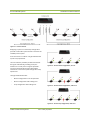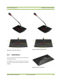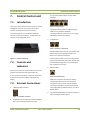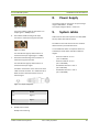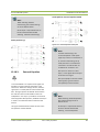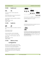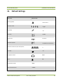
1
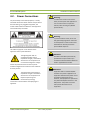
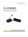
D-CERNO
Wired Conference System
Installation and User Manual
D-Cerno Wired System
Installation and User Manual
Table of Contents
Table of Contents ......................................................................................................................... 3
Section 1 – General Information ................................................................................................... 7
1.
Copyright Statement...................................................................................................... 9
2.
Trademarks ..................................................................................................................10
3.
Conformity info ............................................................................................................10
4.
Safety Instructions ........................................................................................................10
4.1.
4.2.
Important safety instructions ........................................................................................10
Power Connections .......................................................................................................13
5.
D-Cerno System Architecture ........................................................................................14
5.1.
5.2.
System components .....................................................................................................14
Network structure ........................................................................................................14
Section 2 – System Components ..................................................................................................17
6.
Table Top Delegate units ..............................................................................................19
6.1.
6.2.
6.3.
6.4.
6.4.1.
6.4.2.
Introduction .................................................................................................................19
Controls and indicators .................................................................................................19
Installation ...................................................................................................................21
Microphones ................................................................................................................22
Introduction ...................................................................................................................... 22
Electrical and acoustic properties ..................................................................................... 22
6.5.
6.5.1.
6.5.2.
Maintenance ................................................................................................................23
General ............................................................................................................................. 23
Cleaning ............................................................................................................................ 23
7.
Central Control unit ......................................................................................................24
7.1.
7.2.
7.3.
Introduction .................................................................................................................24
Controls and indicators .................................................................................................24
External Connections ....................................................................................................24
8.
Power Supply ...............................................................................................................25
Televic Conference Systems
V2.0 - May 16, 2012
3
D-Cerno Wired System
9.
Installation and User Manual
System cables ...............................................................................................................25
Section 3 – Configuring the system ..............................................................................................27
10.
Menu Navigation ..........................................................................................................29
11.
Menu overview ............................................................................................................29
Section 4 – The Menu explained ..................................................................................................34
12.
Main Menu...................................................................................................................35
12.1.
12.2.
12.2.1.
12.2.2.
12.2.3.
Loudspeaker volume.....................................................................................................35
Conference modes ........................................................................................................35
Direct Access ..................................................................................................................... 35
Override (1-8) .................................................................................................................... 35
With request ..................................................................................................................... 36
12.3.
12.3.1.
12.3.2.
12.3.3.
Vox setting ...................................................................................................................36
Pencil drop ........................................................................................................................ 36
Sensitivity .......................................................................................................................... 36
Release time ...................................................................................................................... 37
12.4.
12.5.
12.6.
12.7.
12.7.1.
12.7.2.
Microphone preset .......................................................................................................37
Microphone Limit .........................................................................................................37
Eco mode .....................................................................................................................38
Settings menu ..............................................................................................................38
Factory settings ................................................................................................................. 38
System info........................................................................................................................ 38
12.8.
Headphone volume ......................................................................................................38
12.9.
Chime...........................................................................................................................38
12.10. External processing .......................................................................................................38
12.10.1. Independent aux settings .................................................................................................. 38
12.10.2. Remote Conferencing ........................................................................................................ 38
12.10.3. External Equalizer .............................................................................................................. 39
12.11.
12.12.
12.13.
Audio out .....................................................................................................................40
Audio In .......................................................................................................................40
Master-slave configuration ...........................................................................................40
Section 5 – Appendix ...................................................................................................................41
13.
Default Settings ............................................................................................................42
14.
Technical Data ..............................................................................................................44
Televic Conference Systems
V2.0 - May 16, 2012
4
D-Cerno Wired System
14.1.
14.2.
14.3.
14.4.
Installation and User Manual
Electrical and Electro Acoustical Characteristics .............................................................44
Mechanical Characteristics............................................................................................44
Environmental Characteristics .......................................................................................44
System limits ................................................................................................................44
Televic Conference Systems
V2.0 - May 16, 2012
5
D-Cerno Wired System
Installation and User Manual
Section 1 – General Information
Televic Conference Systems
V2.0 - May 16, 2012
7
D-Cerno Wired System
1.
Installation and User Manual
Copyright Statement
No part of this publication or documentation
accompanying this product may be reproduced in
any form or by any means or used to make any
derivative such as translation, transformation, or
adaptation without the prior written permission of
the publisher, except in case of brief quotations
embodied in critical articles or reviews. Contents are
subject to change without prior notice.
Copyright© 2011 by Televic Conference NV. All rights
reserved.
The authors of this manual have made every effort in
the preparation of this book to ensure the accuracy
of the information. However, the information in this
manual is supplied without warranty, either express
or implied. Neither the authors, Televic Conference
NV, nor its dealers or distributors will be held liable
for any damages caused or alleged to be caused
either directly or indirectly by this book.
Televic Conference Systems
V2.0 - May 16, 2012
9
D-Cerno Wired System
2.
Installation and User Manual
1.
Trademarks
All terms mentioned in this manual that are known
to be trademarks or service marks have been
appropriately capitalized. Televic Conference NV
cannot attest to the accuracy of this information. Use
of a term in this book should not be regarded as
affecting the validity of any trademark or service
mark.
3.
The safety and operating instructions should be
retained for future reference.
2.
All warnings on the product and the operating
instructions should be adhered to.
3.
4.
The D-Cerno Wired Conference system is compliant
with following standards:
4.
Heed Warnings
Follow Instructions
All instructions for installation or operating / use
should be followed.
Conformity info
•
•
•
Retain Instructions
EN60065
EN55103-1/-2
IEC60914
Unplug this product from the wall outlet before
cleaning. Do not use liquid cleaners or aerosol
cleaners. Use a damp cloth for cleaning.
5.
Safety Instructions
The D-Cerno Conference system is state of the art
and has been designed to meet quality.
Nevertheless, the individual components of the
conference system can cause danger for persons and
material assets if
Cleaning
Ventilation
Slots and openings in the cabinet are provided for
ventilation and to ensure reliable operation of the
product and to protect it from overheating. These
openings must not be blocked or covered. The
openings should never be blocked by placing the
product on a bed, sofa, rug, or other similar surface.
This product should not be placed in a built-in
installation such as a bookcase or rack unless proper
ventilation is provided or the manufacturer's
instructions have been adhered to.
−
the conference system is not used as intended,
−
the conference system is set up by personnel not
familiar with the safety regulations,
−
the conference system is converted or altered
incorrectly,
The product should be situated away from heat
sources such as radiators, heat registers, stoves, or
other products (including amplifiers) that produce
heat.
−
the safety instructions are not observed.
7.
6.
Heat
Attachments
4.1. Important safety
instructions
Do not use attachments not recommended by the
product manufacturer as they may cause hazards.
1.
Do not use this product near water or in a moistures
environment - for example, near a bath tub, wash
bowl, kitchen sink, or laundry tub; in a wet
8.
Read Instructions
All the safety and operating instructions should be
read before the product is operated.
Televic Conference Systems
Water and Moisture
V2.0 - May 16, 2012
10
D-Cerno Wired System
Installation and User Manual
basement; or near a swimming pool, in an
unprotected outdoor installation; and the like.
9.
Accessories
Only use attachments/accessories specified by the
manufacturer. Do not place this product on an
unstable cart, stand, tripod, bracket, or table. The
product may fall, causing serious injury to a child or
adult, and serious damage to the product. Use only
with a cart, stand, tripod, bracket, or table
recommended by the manufacturer, or sold with the
product. Any mounting of the product should follow
the manufacturer's instructions, and should use a
mounting accessory recommended by the
manufacturer.
10. Moving
A product and cart combination should be moved
with care. Quick stops, excessive force, and uneven
surfaces may cause the product and cart
combination to overturn.
14. Power-Cord Protection
Power-supply cords should be routed to that they
are not likely to be walked on or pinched by items
placed upon or against them, paying particular
attention to cords at plug, convenience receptacles,
and the point where they exit from the product.
15. Lightning
For added protection for this product during a
lightning storm, or when it is left unattended and
unused for long periods of time, unplug it from the
wall outlet. This will prevent damage to the product
due to lightning and power-line surges.
Not applicable when special functions are to be
maintained, such as evacuation systems
11. Power Sources
This product should be operated only from the type
of power source indicated on the marking label. If
you are not sure of the type of power supply to your
home, consult your product dealer or local power
company. For products intended to operate from
battery power, or other sources, refer to the
operating instructions.
12. Power Lines
An outdoor system should not be located in the
vicinity of overhead power lines or other electric light
or power circuits, or where it can fall into such power
lines or circuits. When installing an outdoor system,
extreme care should be taken to keep from touching
such power lines or circuits, as contact with them
might be fatal. U.S.A. models only - refer to the
National Electrical Code Article 820 regarding
installation of CATV systems.
13. Grounding or Polarization
Do not defeat the safety purpose of the polarized or
ground-type plug. A polarized plug has two blades
Televic Conference Systems
with one wider than the other. A grounding type plug
has two blades and a third grounding prong. The
wider blade or the third prong are provided for your
safety. If the provided plug does not fit into your
outlet, consult an electrician for replacement of the
obsolete outlet.
16. Overloading
Do not overload wall outlets, extension cords or
integral convenience receptacles as this can result in
a risk of fire or electric shock.
17. Object and Liquid Entry
Never push objects of any kind into this product
through openings as they may touch dangerous
voltage points or short-out parts that could result in
a fire or electric shock. Never spill liquid of any kind
on the product.
18. Inflammable and Explosive Substance
Avoid using this product where there are gases, and
also where there are inflammable and explosive
substances in the immediate vicinity.
19. Heavy Shock or Vibration
When carrying this product around, do not subject
the product to heavy shock or vibration.
V2.0 - May 16, 2012
11
D-Cerno Wired System
Installation and User Manual
20. Servicing
Do not attempt to service this product yourself as
opening or removing covers may expose you to
dangerous voltage or other hazards. Refer all
servicing to qualified service personnel.
21. Damage Requiring Service
Unplug this product from the wall outlet and refer
servicing to qualified service personnel under the
following conditions:
a.
When the power-supply cord or plug is
damaged.
b.
if liquid has been spilled, or objects
have fallen into the product.
c.
If the product has been exposed to rain
or water.
d.
If the product does not operate
normally by following the operating
instructions. Adjust only those controls
that are covered by the operating
instructions as an improper adjustment
of other controls may result in damage
and will often require extensive work by
a qualified technician to restore the
product to its normal operation.
e.
If the product has been dropped or
damaged in any way.
f.
When the product exhibits a distinct
change in performance-this indicates a
need for service.
Upon completion of any service or repairs to this
product, ask the service technician to perform safety
checks to determine that the product is in proper
operating condition.
24. Coax Grounding
If an outside cable system is connected to the
apparatus, be sure the cable system is grounded.
U.S.A. models only: Section 810 of the National
Electrical Code, ANSI/NFPA No.70-1981, provides
information with respect to proper grounding of the
mount and supporting structure, grounding of the
coax to a discharge apparatus, size of grounding
conductors, location of discharge unit, connection to
grounding electrodes, and requirements for the
grounding electrode.
22. Replacement Parts
When replacement parts are required, be sure the
service technician has used replacement parts
specified by the manufacturer or have the same
characteristics as the original part. Unauthorized
substitutions may result in fire, electric shock, or
other hazards.
23. Safety Check
Televic Conference Systems
V2.0 - May 16, 2012
12
D-Cerno Wired System
Installation and User Manual
4.2. Power Connections
Warning:
For permanently connected equipment, a readily
accessible disconnect device shall be incorporated in
the fixed wiring; For pluggable equipment, the
socket-outlet shall be installed near the equipment
and shall be easily accessible.
To reduce the risk of fire or electric
shock, do not expose this appliance to
rain or moisture. Do not open the
cabinet; refer servicing to qualified
personnel only.
Warning:
To prevent electric shock, do not use
this (polarized) plug with an extension
cord receptacle or other outlet unless
the blades can be fully inserted to
prevent blade exposure.
This label may appear on the bottom of the
apparatus due to space limitations.
The lightning flash with an
arrowhead symbol, with an
equilateral triangle, is intended to
alert the user to the presence of
un-insulated ‘dangerous voltage’
within the products enclosure that may be of
sufficient magnitude to constitute a risk of electric
shock to persons.
The exclamation mark within an
equilateral triangle is intended to
alert the user to the presence of
important operating and
maintenance (servicing)
instructions in the literature accompanying the
appliance.
Televic Conference Systems
V2.0 - May 16, 2012
Attention:
Installation should be performed by
qualified service personnel only in
accordance with the National Electrical
Code or applicable local codes.
Attention:
Equipment with or without ON/OFF
switches have power supplied to the
equipment whenever the power cord is
inserted into the power source;
however, the equipment is operational
only when the ON/OFF switch is in the
ON position. The power cord is the
main power disconnect for all
equipment.
13
D-Cerno Wired System
5.
Installation and User Manual
−
D-Cerno System
Architecture
Delegate unit
o D-Cerno D
o Conference system cable (2m)
−
Chairman unit
The D-Cerno system is a digital discussion system for
small to medium size conference rooms.
The main characteristics of the system are:
−
Cristal clear audio reproduction: digital signal
processing, high quality GSM interference free
microphone and loudspeaker, resulting in
excellent intelligibility.
−
Attractive, stylish design: contemporary,
unobtrusive and low profile, fitting into
modern and traditional style conference rooms
−
Plug and Play: easy installation, up and running
in no time, ideal for frequently changing
environments
−
High reliability: built-in redundancy feature –
touch sensor technology, hygienic, easy to
clean, equal performance over the entire
lifespan of the product.
5.1. System components
Central unit
o
o
o
o
o
−
o
o
o
o
o
(Art. 71.98.0320)
D-Cerno CU
D-Cerno PS
Mains cable
Conference system cable (2m)
Quick guide
Central unit-R
o D-Cerno C
o Conference system cable (2m)
−
Spare power supply
−
o D-Cerno PS
o Mains cable
System cables, available in different lengths
(Art. 71.98.0340)
o DCC2 2m cable set: 4 x 2 m
(Art. 71.98.0345)
o DCC5 5m cable set: 4 x 5 m
(Art. 71.98.0346)
o DCC10 10m cable set: 4 x 10 m
(Art. 71.98.0347)
o DCC20 20m cable set: 2 x 20 m
(Art. 71.98.0348)
Detailed info about the different components can be
found in Section 2 of this manual.
5.2. Network structure
The network can be structured in two way:
−
Branch configuration
−
Closed loop configuration
Each branch, loop can handle a maximum of 25 units
if the total cable length is respected.
(Art. 71.98.0321)
D-Cerno CU-R
D-Cerno PS
Mains cable
Conference system cable (2m)
Quick guide
(Art. 71.98.0302)
The central unit can control and power a total of 50
units over the four available conference ports.
A D-Cerno system consists out of the following
components:
−
(Art. 71.98.0301)
The total cable length of a branch / loop cannot
exceed the maximum of 400 m.
The max cable length between units or between
units and central unit is 80 m.
The maximum power consumption of a unit is 2W.
Televic Conference Systems
V2.0 - May 16, 2012
14
D-Cerno Wired System
Installation and User Manual
Below a graphical representation of a D-Cerno
configuration.
At the left side a branch configuration connected to
port 1.
At the right a closed loop configuration between port
3 and 4.
Televic Conference Systems
V2.0 - May 16, 2012
15
D-Cerno Wired System
Installation and User Manual
Figure 5.1 : D-Cerno network
Designing a system in a closed loop configuration
provides a redundant system and thus increases the
reliability of the system.
If for some reason a cable or unit gets defective the
system stays operational.
The units have the possibility to detect the flow of
the signal automatically providing a free port
selection. If at some point no signal is provided
anymore, automatically the signal flow will be
reversed. As a result the system configuration stays
operational.
Figure 5.2 : D-Cerno branch configuration, no error
The figures below illustrates:
−
Branch configuration in normal operation
−
Branch configuration with cabling error
−
Loop configuration with cabling error
Figure 5.3 : D-Cerno branch configuration, cable error
Figure 5.4 : D-Cerno loop configuration, cable error
Televic Conference Systems
V2.0 - May 16, 2012
16
D-Cerno Wired System
Installation and User Manual
Section 2 – System Components
Televic Conference Systems
V2.0 - May 16, 2012
17
D-Cerno Wired System
6.
Installation and User Manual
Table Top Delegate
units
6.1. Introduction
7.
NEXT button: (chairman unit only)
Grants the floor to the next delegate in the
waiting list.
8.
PRIOR button: (chairman unit only)
permanently deactivates the microphone of all
active units.
The contribution units consist out of delegate and
chairman units. Both are used for speech
reinforcement in a conference room. The chairman
units are used to guide and control an ongoing
discussion.
6.2. Controls and
indicators
The D-Cerno delegate units have the following
features:
1.
Microphone touch sensor button:
Activation/deactivation of the microphone.
Indication LEDs show the status of the
microphone. (red : active, green : request)
2.
Loudspeaker:
Distributes the floor channel. Mutes in case
microphone is active.
3.
Headphone connector:
Connection of headphone to the unit. Monoand stereo headphones can be used.
4.
Volume touch sensor buttons:
Change the volume level of the headphones.
Remark: volume change is only possible when a
headphone is connected
5.
Microphone
6.
Led bar
Indicates the status of the unit.
Red : unit is active
Green : unit is in request mode
Pressing the Next-in-line or PRIOR button on a
chairman unit is indicated by illuminating the
corresponding part of the led bar.
Televic Conference Systems
V2.0 - May 16, 2012
19
D-Cerno Wired System
Installation and User Manual
Figure 6.2.2: D-Cerno Chairman Unit
Figure 6.2.1: D-Cerno Discussion Unit
6.3. Installation
D-Cerno units offer free input/output connectivity to
allow flexible cabling.
The delegate units can be connected as a daisy chain
branch or in loop to ensure redundancy and increase
reliability.
Figure 6.3: D-Cerno connectivity
Televic Conference Systems
V2.0 - May 16, 2012
21
D-Cerno Wired System
Installation and User Manual
Make sure that the units are not positioned too close
to each other. It is recommended to keep a distance
of 1m between the units to prevent howling.
6.4. Microphones
6.4.1. Introduction
The recommended speaking distance for people to
speak to the microphone is between 20 to 40 cm.
The D-Cerno microphone has a uni-directional
response for optimum performance even in noisy
conditions, and has a very low susceptibility to
interference from mobile phones.
6.4.2. Electrical and
acoustic properties
Table 6.4.2: Microphone characteristics
Transducer type
Back electret (condenser)
Operating principle
Pressure gradient
Polar pattern
Uni-directional,
cardioid
Frequency response
130 Hz – 150000 Hz
Nominal impedance
Televic Conference Systems
1kOhm (at 1 kHz, drop resistance =
1k2, Vdd = 3.3VDC )
Load impedance
> 5kOhm
Max.SPL at 1 kHz
120 dB SPL
Free field sensitivity
7mV/Pa, +/- 3 dB at 1 kHz or
(-43dB, 0dB=1V/Pa at 1kHz)
Power supply
3.3V DC, 0.5 mA
Consumption
0.5 mA (without LED ring);
max. 25 mA (with illuminated ring)
V2.0 - May 16, 2012
22
D-Cerno Wired System
Installation and User Manual
6.5. Maintenance
6.5.1. General
Caution:
Do not put any objects on top of the
units. Object falling through the holes of
the unit can cause damage.
Caution:
Do not install the units in a location near
heat sources as radiators, air ducts or
direct sunlight.
Caution:
Make sure the units are not exposed to
excessive dust, humidity, mechanical
vibration or shock.
6.5.2. Cleaning
Caution:
Do not use alcohol, ammonia or
petroleum solvents or abrasive cleaners
to clean the units.
To keep its original condition it is advised to
periodically clean the unit:
•
Use a clean soft cloth that is not fully moist.
•
Make sure the device is completely dry
before usage.
Televic Conference Systems
V2.0 - May 16, 2012
23
D-Cerno Wired System
7.
Installation and User Manual
For more information please use the power
calculator
Central Control unit
7.1. Introduction
The D-Cerno CU is the heart of the system. It controls
all delegate units and can interconnect to other
systems via the external audio connections.
Figure 7.3 : System ports
The green indicator points to detected signal,
without errors (devices detected).
The yellow indicator points to error or no signal
detected (no devices connected)
The system operates in a standalone mode and
controls a maximum of 50 units. Configuration can
be done via the integrated menu.
3.
2 x RJ45 ports
Figure 7.4 : Master – Slave ports
2 RJ-45 shielded connectors for a connection with
2 slave central units when the central unit is
master in a coupled environment.
In Case a larger number of units are required the
system can be extended with 2 extra central units
in master/slave configuration. The maximum of
units is 150 (3 central units).
Figure 7.1 : D-Cerno connectivity
7.2. Controls and
indicators
4.
LAN connector
All controls are done via touch panel by means of an
intuitive user interface menu (see chapter 11)
A user can activate or select a control or menu item
by touching one of the symbols underneath the
display.
Figure 7.5 : LAN connector
Webserver connection (D-Cerno CU-R only)
Through the LAN connector it is possible to
connect the central unit to the local network.
This makes it possible to control the recording
and configuration by web browser on your PC or
mobile device.
7.3. External Connections
1.
+48V DC power connector
5.
Two unbalanced RCA audio output connectors to
extract analog audio floor signal
Figure 7.2 : DC power connector
2.
4 x RJ45 ports to connect up to max 50 delegate
units. (max. 25 units per branch or loop).
Televic Conference Systems
V2.0 - May 16, 2012
24
D-Cerno Wired System
Installation and User Manual
8.
6.
Power Supply
Figure 7.6 : Aux Out
The power supply can operate on an input voltage
range of 100-240Vac , 47-63Hz.
The output voltage is 48V dc – 3.15A max
The green indicators light up when there is an
output signal > -40dBV present
9.
One unbalanced RCA analog audio input
connector to add external signal to the floor
System cables
Cables used in the D-Cerno system are Cat5e (AWG
24 FTP) cables with RJ45 connectors.
Contribution units and central units are standard
delivered with a premade cable of 2m.
Figure 7.7 : Aux in
The red indicators light up when there is an
overload of the input signal (signal > +9dBV)
In case additional cables are required Televic has
standard pre-made cables available in different
lengths.
-
7.
One balanced XLR analog audio connector to
add external signal to the floor
The red indicators light up when there is an
overload of the input signal.
The AUX In connections on the central unit have
a XLR 3 Female connector. So a cable with XLR 3
Male connector should be used to insert an
external signal.
-
DCC2 2m cable set: 4 x 2 m
(Art. 71.98.0345)
DCC5 5m cable set: 4 x 5 m
(Art. 71.98.0346)
DCC10 10m cable set: 4 x 10 m
(Art.71.98.0347)
DCC20 20m cable set: 2 x 20 m
(Art. 71.98.0348)
Figure 7.8 : XLR pin assignment
Pin 1
Shield
Pin 2
Signal +
Pin 3
Signal -
8.
Headphone connector
Headphone monitoring.
Televic Conference Systems
V2.0 - May 16, 2012
25
D-Cerno Wired System
Installation and User Manual
Section 3 – Configuring the system
Televic Conference Systems
V2.0 - May 16, 2012
27
D-Cerno Wired System
Installation and User Manual
The main system volume can be adapted with the < >
keys or via the dedicated volume buttons.
10. Menu Navigation
The menu consists out of several levels. Each level
functions as a ring structure navigating from the last
to first item or vice versa.
Enter the configuration menu
Enter the next menu level
The D-cerno CU-R has 3 extra record buttons. With
this buttons it is possible to start/stop or pause a
recording.
start recording
^
Return to previous menu level
<
Select previous menu item
>
Select next menu item
Stop recording
Highlight of selected item
Listen/ pause recording
After start-up of the system, the main menu shows
up.
The loudspeaker volume settings can be done
directly on the central unit.
11. Menu overview
The main menu consists of a system volume section
and a configuration menu entrance.
Televic Conference Systems
The menu structure on the next pages can be used as
a quick reference guide to configure the conference
systems.
V2.0 - May 16, 2012
29
D-Cerno Wired System
Televic Conference Systems
Installation and User Manual
V2.0 - May 16, 2012
30
D-Cerno Wired System
Installation and User Manual
Level
L1
L2
Description
L3
Microphone mode
Direct Speak
Toggle
Push to talk
Override
Toggle
VOX
Request
Vox settings
Pencil drop
Pencil drop on
Pencil drop off
Sensitivity
Sensitivity adjustment
Release time
Release time adjustment
Microphone sensitivity preset
Preset Far
Preset Average
Preset Close
Number of active speakers allowed
Representation of speaker, maximum 8
Eco Power
Eco Power on
Televic Conference Systems
V2.0 - May 16, 2012
31
D-Cerno Wired System
Installation and User Manual
Eco power off
Settings menu
Factory settings
Factory settings OFF
Activate factory settings
System information
Information about software and hardware versions of the central unit
Headphone volume
Headphone volume adjustment
Chime
Chime on
Chime off
External processing
Independent aux settings
External Processing
Remote Conferencing
Auxiliary OUT settings
Aux OUT 1
Aux OUT 1 volume adjustment
Aux OUT 2
Aux OUT 2 volume adjustment
Auxiliary IN settings
Aux IN 1
Aux IN 1 volume adjustment
Aux IN 2
Aux IN 2 volume adjustment
Televic Conference Systems
V2.0 - May 16, 2012
32
D-Cerno Wired System
Installation and User Manual
Master/slave configuration
Slave configuration
Master conifguration
Televic Conference Systems
V2.0 - May 16, 2012
33
D-Cerno Wired System
Installation and User Manual
Section 4 – The Menu explained
Televic Conference Systems
V2.0 - May 16, 2012
34
D-Cerno Wired System
Installation and User Manual
12. Main Menu
Config menu selection
allows entering the
different settings as described below
All selected settings are activated immediately
except for “restore factory settings” which needs
additional confirmation.
12.1. Loudspeaker volume
The chairman can cancel all the active microphones
by short pressing the PRIOR icon. This can cause a
chime audio signal ( If this setting is active see
chapter 12.9)
Holding the PRIOR button will temporarily mute all
active microphones. Releasing the button will return
the state of the microphone before the PRIOR button
was pressed.
Activation mode
Adjust the loudspeaker volume of the system.
The loudspeakers setting are the same as for a
delegate as for a chairman.
Loudspeaker volume is adjustable between 0dB and 46dB + “OFF”
12.2. Conference modes
Toggle
Represented by animation sequence
In order to guide a conference several conference
modes are available.
Chairman microphones are not affected by any
conference mode and can be activated at any time
with a maximum of 8 chairman units.
The microphone icon needs to be pressed to activate
the unit and once more to deactivate the unit.
Push to talk
Represented by animation sequence
12.2.1. Direct Access
Enables the participant to turn on his microphone at
any time by pressing the MIC icon on his conference
unit.
Several participants can be active simultaneously
until the microphone limit setting (see chapter 12.5)
is reached.
Televic Conference Systems
In the direct access mode there is an additional
setting to define the way a delegate is granted the
floor.
The microphone is only active as long as the MIC icon
is pressed.
12.2.2. Override (1-8)
Makes it possible to activate 1 to 8 delegates
simultaneously depending on microphone limit
setting (see chapter 12.5)
V2.0 - May 16, 2012
35
D-Cerno Wired System
Installation and User Manual
Whenever the microphone limit is reached, and a
delegate presses the microphone icon, the longest
active microphone will be deactivated.
The chairman can cancel all the active microphones
by short pressing the PRIOR icon.
A unit in request is visualized via the green light bar
on the delegate unit and by blinking the microphone
led ring.
The chairman can activate delegate unit that are in
request state by pressing the NEXT icon on his unit.
Holding the PRIOR button will temporarily mute all
active microphones. Releasing the button will return
the state of the microphone before the PRIOR button
was pressed.
Activation mode
The light bar of first delegate unit in the queue list
will become red and the microphone will be
activated.
The chairman can cancel all the active microphones
by short pressing the PRIOR icon.
In the override mode there is an additional setting to
define the way a delegate is granted the floor.
Toggle
Holding the PRIOR button will temporarily mute all
active microphones. Releasing the PRIOR button will
return the status of the microphones as before the
PRIOR button was pressed.
Represented by animation sequence
The microphone icon needs to be pressed to activate
the unit and once more to deactivate the unit.
12.3. Vox setting
VOX
12.3.1. Pencil drop
The microphone of the delegates will be activated
based on the fact that they start to talk. Once they
stop talking the microphone will automatically be
switched off when the release time has expired (see
chapter 0).
12.2.3. With request
This setting allows the elimination of the activation
of microphones by short sounds. For example when a
pencil is dropped on a desk
The Pencil drop setting can be set on or off.
12.3.2. Sensitivity
Whenever the microphone limit is reached pressing
the MIC icon will add the delegate in a waiting list.
The unit will enter into request state.
Televic Conference Systems
V2.0 - May 16, 2012
36
D-Cerno Wired System
Installation and User Manual
Each room has a different acoustic. With this setting
it is possible to adjust the sensitivity of the VOX
mode.
The voice activation of a microphone is triggered by
a sound level , adjustable between 0 and -24 dBFs.
12.3.3. Release time
A voice activated microphone will be switched off
when, during a certain time ,no sound was detected .
This time is adjustable between 1 and 10 seconds.
Change in distance between speaker and
microphone to obtain the same output
level
Close
distance reference
Average
distance reference x 2
Far
distance reference x 4
There is also a fixed automatic gain reduction setting
that reduces the volume per active microphone
depending on the total number of active
microphones. See graph below:
12.4. Microphone preset
There are 3 limiter gain presets to choose from. The
choice between these 3 will depend on the distance
between the speaker and the microphone.
This setting influences the sensitivity and the
dynamic range of the microphones.
auto gain reduction (dB)
Auto gain reduction
0
-2
-4
-6
-8
-10
-12
0
Each step (far, average and close) causes a halving or
doubling off the distance from the speaker to the
microphone to have the same output level
5
10
#Mic ON
12.5. Microphone Limit
Below you can find the relation between microphone
sensitivity preset, used distances between
microphone and speaker and output level.
Relative output level at fixed distance
between microphone and speaker
Close
Level reference
Average
Level reference + 6dB
Far
Level reference + 12dB
The maximum open microphones at the same time
can be chosen between 1 and 8.
The value of this menu item is represented by a
number of delegate icons.
e.g. 4 open microphones
On top of the maximum number of active delegates
it is possible to activate a maximum of 8 chairman
units.
Televic Conference Systems
V2.0 - May 16, 2012
37
D-Cerno Wired System
Installation and User Manual
12.6. Eco mode
12.9. Chime
The central unit has an ECO function that is going
into low power mode after the system has not been
used for a certain period.
Whenever the chairman uses the prior button, a
chime tone will be audible
The chime mode can be set on or off.
The eco mode can be set on or off.
12.10.
12.7. Settings menu
External processing
12.10.1.
Independent aux
settings
12.7.1. Factory settings
Auxiliary input and output settings are independent
form each other and allow external signal to be
added to the floor and to extract the total floor signal
Audio path for Independent Aux settings.
When the factory settings reset is selected and
confirmed, the CU will reboot with its default
settings. (See chapter 13)
12.7.2. System info
Displays general system info as shown in example
below
Serial number and software version
SN
V
10552685
v 010C
Figure 12.1 : Normal audio path
12.10.2.
Remote Conferencing
12.8. Headphone volume
Adjust the headphone volume of the CU
The headphone volume of the central unit can be
adjusted via the central unit menu.
Televic Conference Systems
Remote conferencing option gives the possibility to
connect a central unit to e.g. a video conferencing
system or telephone coupler. To prevent echoing,
the remote conferencing option needs to be set.
V2.0 - May 16, 2012
38
D-Cerno Wired System
Installation and User Manual
Audio path for external equalizer Mode
Note:
When selecting “Remote
conferencing, Aux volume settings
are set to default values!
So Aux input – output levels have to
be set to desired values AFTER
selecting “Remote conferencing”
Audio path for N_1
Figure 12.3 : External equalizer audio path
Note:
“Remote conferencing” and
“External Equalizer” audio paths
apply only to Aux In 1 and Aux Out 1.
In “remote conferencing” setup
mode, Aux Out 1 is considered as
“local floor” out and Aux Out 2 is
considered as “total floor” out.
Figure 12.2 : Remote conferencing audio path
12.10.3.
Aux Input 1 is used as “Far End
input”, so this signal will not be part
of the Aux Out 1 signal.
External Equalizer
To avoid feedback or to equalize audio signals it is
possible to connect external equipment to the
central unit. When this setting is chosen, the floor
signal (mics + Aux IN2) will be routed to both AUX
OUT. The signal present at AUX IN1 will be used as
the new floor channel and audible on the units
loudspeakers. This way it is possible to use external
audio equipment like equalizers, feedback destroyers
or mixers. The schematic below summarizes this
feature.
The signal at both AUX OUT will be the sum of the
microphones and the AUX IN2.
Televic Conference Systems
V2.0 - May 16, 2012
Aux Input 2 (XLR) can also be used to
add a signal (e.g. from external
microphones) to the local floor.
Note:
When selecting “External equalizer”,
Aux volume settings are set to
default values!
So Aux input – output levels have to
be set to desired values AFTER
selecting “External Equalizer”
39
D-Cerno Wired System
12.11.
Installation and User Manual
Audio out
The D-Cerno CU has 2 auxiliary output RCA
connectors.
On each output there is also an activity indication.
(Led is on when level > -40dBV)
The output gain is adjustable between +24dB and 51dB + “OFF”
Default gain value = 0dB
10dBV (=0dBFS)
12.12.
If the icon like picture below is selected, the D-cerno
central unit will then act as a master.
Audio In
If the icon like picture below is selected, the D-cerno
central unit will then act as a slave.
Two auxiliary line inputs are available on the central
unit.
Aux IN1: RCA connector
Aux IN2: XLR connector
On each input there is also an overload led
indication. (Led is on when input level > 9dBV)
The input gain is adjustable between +24dB and 51dB + “OFF”
Default gain value = 0dB
10dBV (=0dBFS)
The menu of a slave central unit cannot be accessed.
That means that all settings need to be done on the
master central unit. For example: initialization of the
units, volume settings…
The external audio in and output cannot be used on
the slave central unit(s).
12.13. Master-slave
configuration
Whenever an installation requires more than 50
units the system can be extended using 1 or 2 extra
central units in a master/slave configuration.
The system can be extended to a maximum of 150
units. One D-cerno central unit acts like a master
whereas the other central units are configured as
slave units.
Televic Conference Systems
V2.0 - May 16, 2012
40
D-Cerno Wired System
Installation and User Manual
Section 5 – Appendix
Televic Conference Systems
V2.0 - May 16, 2012
41
D-Cerno Wired System
Installation and User Manual
13. Default Settings
Menu Item
Default Value
Operating Mode
Direct Access
Activation mode
Toggle
Pencil drop
On
Sensitivity
-24 dBFs
Release time
4 seconds
Microphone preset
Far (Maximum sensitivity)
Maximum number of open microphones
4
Eco mode
On
Headphone Volume
-6dBFs
Chime
Off
Loudspeaker Volume
-6dBFS
Output level Aux Out 1
-10 dBFS
Televic Conference Systems
V2.0 - May 16, 2012
42
D-Cerno Wired System
Installation and User Manual
Output level Aux Out 2
-10 dBFS
Input level Aux In 1
OFF
Input level Aux In 2
OFF
Aux-In/Out Mode
Televic Conference Systems
Independent
V2.0 - May 16, 2012
43
D-Cerno Wired System
Installation and User Manual
14. Technical Data
Power supply:
170 x 70 x 35
Including Packing:
215 x 160 x 50
14.1. Electrical and Electro
Acoustical
Characteristics
Weight (g)
Central unit:
1300
Frequency response
25Hz to 15KHz (+/-3dB)
Including packing
(CU + PS + Cable)
2660
Harmonic distortion
≤ 0.02%
Delegate / Chairman unit:
660
Including packing
(unit + cable)
1100
Power supply:
920
Input sensitivity
0dBV= -10dBFS
Input gain adjustment
+24dB to -51dB + “OFF”
Input impedance Aux 1
≥ 7 KΩ (asymm.)
Input impedance Aux2
≥ 20 KΩ (symm.)
Output level
0dBV= -10dBFS
Output gain adjustment
+24dB to -51dB + “OFF”
Output impedance
≤ 600 Ω
Volume control
0dB to -46dB + “OFF”
Headphone output level
14.3. Environmental
Characteristics
Temperature
5°C to 50°C
Humidity
Protection class EP10
Compliant to IEC 60068_2.14
Max 70mW in 32 Ω
Headphone volume control
0dB to -72dB + “OFF”
Headphone impedance =
14.4. System limits
16 Ω to 150 Ω
14.2. Mechanical
Characteristics
Max units on CU
50
Max units on one port
25
Max chairman-units
8
Maximum cable length
(branch or loop)
400 m
Dimensions W x H x D (mm)
Central unit:
300 x 135 x 50
Including Packing :
345 x 250 x 155
Maximum cable length between units
or between CU and first unit
80m
Delegate / Chairman unit: 210 x135 x 50
Including Packing:
335 x 250 x 120
Televic Conference Systems
V2.0 - May 16, 2012
44
For more information visit:
www.televic-conference.com
Data subject to change without notice
Televic Conference Systems
V1.0 - May. 16, 12
46