1
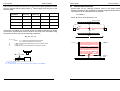
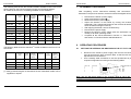
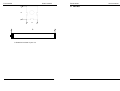
Focus series
User’s manual
Focus series
User’s manual
FOCUS
INFRARED SAFETY BARRIERS
Focus 4 series
Type 4
Focus 2 series
Type 2
The FOCUS Safety barrier complies with CE provisions according to the
following directives:
-98/37/EC Machinery Directive
-73/23/EEC Low-Voltage directive resp. 93/68/EEC
-EN 61496-1:1997
-prEN 61496-2:1997
-DIN V VDE 0801:1990 and amendment A1:1994
-EN 50081-2:1993
-EN 55022:1998
-EN 60204-1:1997 (as applicable)
The barrier is certified by TUV to safety standard EN 61496-1/2 Type 2/4
USER´S MANUAL
MANUFACTURER:
JOKAB SAFETY AB
Boplatsgatan 3
213 76 Malmö
SWEDEN
Tel.
+46 (0)40 143630
FAX.
+46 (0)40 229288
E-Mail
[email protected]
USER’S MANUAL:
Version 1.3 dated 28-04-2003
Focus series
User’s manual
Focus series
User’s manual
11 FINAL CHECKS............................................................................... 31
INDEX
12 ROUTINE CHECKS AND MAINTENANCE..................................... 31
Section
Page
13 GENERAL INFORMATION AND USEFUL DATA .......................... 32
1
BEFORE USE .................................................................................... 5
14 TECHNICAL SPECIFICATIONS FOR FOCUS ............................... 33
2
GENERAL DATA AND MAIN APPLICATIONS................................ 6
15 MF-T AND MF-L MECHANICAL DATA .......................................... 34
3
OPERATION ...................................................................................... 7
16 DIMENSIONS ................................................................................... 34
PRECAUTIONS AND CRITERIA FOR INSTALLATION .................. 8
17 NOTES: ............................................................................................ 36
4
4.1
CALCULATION OF THE MINIMUM DISTANCE FOR INSTALLATION ................. 8
4.2
REFLECTING SURFACES ................................................................................... 10
5
MECHANICAL ASSEMBLY ............................................................ 11
6
CONNECTIONS............................................................................... 12
6.1
CABLE REFERENCES: ........................................................................................ 12
6.2
CONNECTIONS WITH SAFETY RELAY:............................................................. 13
6.3
NOTES ON CONNECTIONS ................................................................................ 15
6.4
CODES AND SPECIFICATIONS OF AVAILABLE MODELS ............................... 16
7
ALIGNMENT PROCEDURE............................................................ 18
8
OPERATING PROCEDURES ......................................................... 18
8.1
SETTING THE INTERNAL DIP-SWITCHES IN THE RECEIVER UNIT............... 18
8.1.1
SELECTION OF RESET MODE. .................................................................. 19
9
MUTING, OVERRIDE AND FLOATING BLANKING FUNCTIONS 20
9.1
GENERAL INFORMATION ON THE THREE FUNCTIONS ................................. 20
9.2
MUTING FUNCTION ............................................................................................ 20
9.3
DESCRIPTION OF SINGLE MODULE MUTING AND MODULAR MUTING ....... 21
9.3.1
DEFINITION OF MODULE............................................................................ 21
9.3.2
SINGLE MODULE MUTING AND MODULAR MUTING. ............................. 22
9.3.3
SELECTION OF MODULAR MUTING MODE ............................................. 22
9.3.4
SELECTION OF SINGLE MODULE MUTING.............................................. 22
9.4
CRITERIA FOR INSTALLATION .......................................................................... 23
9.4.1
MUTING ACTUATOR UNITS MF-T AND MF-L............................................. 26
9.5
TIMING CONSTRAINTS (muting function) ........................................................... 26
9.6
OVERRIDE............................................................................................................ 27
9.6.1
ENABLING THE OVERRIDE FUNCTION .................................................... 27
9.7
FLOATING BLANKING ......................................................................................... 27
9.7.1
DEFINITION OF FLOATING BLANKING .................................................... 27
9.7.2
MEMORISATION PROCEDURE FOR FLOATING BLANKING .................. 28
10 LED DIAGNOSTICS ........................................................................ 29
10.1
WHAT THE LEDS MEAN...................................................................................... 29
10.2
ERRORS SIGNALLED BY LED INDICATION ...................................................... 30
3
While every effort has been taken to ensure the accuracy of the information contained in this manual JOKAB SAFETY cannot accept responsibility for errors or omissions and
reserves the right to make changes and improvements without notice. It is the users responsibility to ensure that this equipment is correctly designed, specified , installed, cared
for and operated to meet all applicable local, national and international codes/regulations. Technical data given in this manual is correct to the level of accuracy of JOKAB
SAFETY’s test procedures as verified by various international approved bodies. Other information (such as application examples, wiring diagrams, operation or use) is intended
solely to illustrate the various uses of our products. JOKAB SAFETY does not guarantee or imply that the product when used in accordance with such examples in a particular
environment will fulfil and particular safety requirement and does not assume any responsibility or liability for actual use of the product based on the examples given. Printed
in Sweden.
4
Focus series
1
User’s manual
BEFORE USE
Focus series
2
• GENERAL INFORMATION
Before using the Focus barriers all personnel responsible for the
installation and operation of this equipment must ensure that they have
read and are conversant with the information contained in this manual.
It is essential that the Safety Barriers are operated and installed in
accordance with the instructions in this manual. All relevant standards
and regulations regarding the use of this type of device must also be
strictly adhered to.
The barrier does not contain any parts that are subject to maintenance. In
all cases however, the power supply must be disconnected before
proceeding with any internal examination/intervention.
In case of malfunction, the barrier must be sent to our laboratories with a
description of the anomaly found and the length of time the unit has been
in service.
• REGULAR MAINTENANCE
Except for the cleaning of the polycarbonate front covers that protect the
optical elements, the barrier does not contain any parts that are subject to
maintenance. The system however should be regularly checked and
inspection results recorded.
Do not use woollen cloths or solvents or any material that could scratch
or attack the front cover polycarbonate surface.
The interval between cleaning will depend upon the local environmental
conditions in which the barrier is operating.
Note. Any deterioration in the protection covers e.g. by dirt etc. will not
compromise the system’s safety in any way but may cause the barrier to
stop operating.
User’s manual
GENERAL DATA AND MAIN APPLICATIONS
Focus units are safety barriers for use in environments where it is essential
to safeguard the safety of the operator using machinery, robots or other
dangerous automated systems, and where casual and/or unauthorised
access may be gained to hazardous parts.
The barriers provide coverage of the protected area by the generation of
infrared beams, which are able to detect an object located within their field of
operation.
The barriers comply with the requisites for Type 2 (Focus 2 series), and
Type 4 (Focus 4 series) safety devices according to the provisions of the
latest international regulations and IEC 61496 1-2 in particular.
Models are available that provide protection heights of between 150 mm and
1650mm.
All the control and command function electronics are contained within the
profile housing; external connections being made via a M12 connector
situated at the end of the barrier. There are no connections between the
transmitter and the receiver, as synchronisation between the two units is
achieved optically. Control and management of the beams transmitted and
received is achieved by two microprocessors that also provide information
on the status of the barrier via several led indicators. There are two
alignment leds to aid installation.
The muting and override functions are available on all the Focus barrier
models and are enabled by simply connecting the LMS warning light, which
is available separately.
Versions are also available with the floating blanking function: this function
offers the possibility to partially exclude a predetermined ‘floating’ portion of
the barrier.
Note.
Muting, override and floating blanking all effectively override the system and
therefore certain precautions must be put in place to limit the degradation of
the level of safety when these functions are operational.
Jokab Safety AB does not accept any liability for damage or injury due to
incorrect use of the protection barriers or associated components.
5
6
Focus series
3
User’s manual
Focus series
User’s manual
Please remember that by enabling/disabling the muting function the
override function is automatically enabled/disabled.
OPERATION
The barrier consists of two units, one with transmitting optical elements
(Transmitter) and one with receiving optical elements (Receiver). All the
photosensitive elements are regularly scanned in sequence so that any
objects placed between the transmitter and the receiver are detected. Upon
detection the operation of the equipment being controlled is interrupted by
means of the switching of the safety barrier outputs. Barrier response times
vary from 14 to 45ms according to the model. Led indicators display the
operating status of the machinery as well as any anomalies in the reset, test
and muting inputs (for the models with this option).
The operator has a multifunction pushbutton, which is used for the following:
• TEST: If pressed during normal operation, it checks that all the
system, comprising the barrier and the machinery interface, is
operating correctly. Pressing the button (opening contact) basically
simulates the interruption of one or more of the safety barriers beams
making it possible to check that the machinery stops in the time and
way set.
• RESTART: If pressed after the barrier has detected an object,
(manual reset condition) the system will be reset providing there is no
obstruction of the barrier beams
• ALIGNMENT: If the button is pressed when there is no power supply
to the barrier and then power is restored, (whilst the button is being
pressed), the barrier enters alignment mode, i.e. it provides an
indication of the centring of the top and bottom optical beams by
means of two yellow leds.
• OVERRIDE: (only present if the muting function is operational) If the
button is pressed within 5 seconds of switching on the barrier and is
kept pressed for at least 5 seconds, the barrier’s outputs will switch
only if the beams are interrupted. This condition stops as soon as the
button is released or automatically after 120 seconds.
1. Automatic reset: After the barrier has detected an object, it will return to
normal operation as soon as the object is removed.
2. Manual reset: Normal operating mode is only restored after the object has
been removed and the reset button has been pressed.
To enable the muting function, the LMS muting indicator must be connected
when the barrier is not connected to the power supply, as shown in
section 6, and then the barrier’s power supply must be restored. To disable
the muting function, the LMS muting indicator must be disconnected when
the barrier is not connected to the power supply, and then the barrier’s
power supply restored.
7
The outputs of the safety barrier are PNP transistors. Should the load to be
controlled have alternating current or require more than 500mA
consumption, a safety relay is necessary, this converts the transistor
outputs into relay contact outputs whose operation is directly tested and
controlled by the safety relay module itself.
4
PRECAUTIONS AND CRITERIA FOR INSTALLATION
The area where the barrier is to be installed must be compatible with the
device technical specifications. The temperature of the environment,
interference caused by electromagnetic disturbance and sources of light etc,
should be assessed prior to the installation of the barrier.
4.1
CALCULATION OF THE MINIMUM DISTANCE FOR INSTALLATION
The safety distance ‘S’ is the minimum distance that must be maintained
between the safety barrier and the dangerous area/position of the machine.
The safety distance must guarantee that the operator cannot reach the
danger zone before the machines moving parts have stopped. The formula
to calculate the safety distance for multi-beam barriers is as follows:
S=(K*T)+C
S
T
= Safety distance.
= T1 + T2
where T1 = machinery’s response time in seconds.
T2 = barrier’s response time in seconds.
= approach speed of the body to the danger zone:
2000 mm/s for Fx-14 or 35 models, 1600mm/s for Fx-K models
=8*(d-14)mm for Fx-14 or 35 models, 850 mm for Fx-K models where d is the
minimum object that can be detected (35mm for Fx-35 and 14mm for Fx-14)
K
C
S
H2
H1
S = safety distance.
H1 = the bottom beam must not have a height above 300 mm .
H2 = the top beam must not be below 900 mm .
8
Focus series
User’s manual
The Focus Fx-K series has beams set to meet the accepted standards. Please
note the required bottom beam height (1st beam height) from the floor in the
following table.
4 Beams
Beam height
(900 unit)
from floor
1st Beam height 300 mm
4 Beams
(1200 unit)
300 mm
3 Beams
2 Beams
300 mm
400 mm
2nd Beam height 600 mm
700 mm
700 mm
900 mm
3rd Beam height 900 mm
1100 mm
1100 mm
4th Beam height 1200 mm
1500 mm
Focus series
User’s manual
4.2 REFLECTING SURFACES
Should there be any reflecting surfaces close to the safety barrier, the
clearance distance must be sufficient to safeguard against passive reflections.
The distance can be calculated with the formula:
A = 0.04366 * L
where ‘A’ and ‘L’ are expressed in mm
Reflecting material
FR unit
FT unit
A
2,5°
2,5
If the barrier is installed in a horizontal position the distance between the danger
zone and the furthest beam must be equal to the result of the calculation using
the previous formula, but with the following parameters:
Object
A
Reflecting surface
S=(K*T)+C
L
T= T1 + T2
where
K
C
H
T1 = machinery’s response time in seconds.
T2 = barrier’s response time in seconds.
= 1600 mm/s (approach speed of the body to the danger zone).
= 1200 - 0.4 * H.
= height (in mm) of the optical beams compared to the floor.
RX
FRbarunit
FT
TX unit
bar
L
object
S
2,5°
A
Reflecting
surface
H
S = safety distance.
H = the optical beam must have a height between 225 mm and 1000mm.
9
10
Focus series
User’s manual
If several barriers are used, care must be taken that each transmitter does
not interfere with the receiver of a nearby barrier. Barriers should be installed
as below:
TRANSMITTER
FT unit
5
RECEIVER
FR unit
RECEIVER
FR unit
Focus series
6
6.1
User’s manual
CONNECTIONS
CABLE REFERENCES:
TRANSMITTER
FT unit
MECHANICAL ASSEMBLY
Use the appropriate brackets provided to complete the mechanical
assembly.
The fixing brackets for the transmitter/receiver units slide in the profile slots
so that they can be placed at an equal distance from each other.
OK
NO
NO
Note. A N/C. voltage free contact from a button or an automatic device, such
as a PLC, must be connected across the Test/Restart input 1.
11
12
Focus series
6.2
User’s manual
Focus series
User’s manual
Connection scheme if a safety relay is connected to the muting activator unit
MF-L or MF-T which is added to the safety barrier.
CONNECTIONS WITH SAFETY RELAY:
Note. Do not make the connections shown in bold type if the muting
function is not required.
Test/Restart pushbutton no 1. has a multifunction (see Section 3 Operation
Page 7). Normally this is the button to use and button no 2 is bypassed.
The safety relay is connected for (*) automatic reset.
Test/Reset pushbutton no 2. Safety Relay Manual reset. This button can be
used if the barrier is set internally for automatic restart and button 1. Is
bypassed or connected and used for alignment only.
Test/Restart pushbutton no 1. has a multifunction (see Section 3 Operation
Page 7). Normally this is the button to use and button no 2 is bypassed.
The safety relay is connected for (*) automatic reset.
Test/Reset pushbutton no 2. – Safety Relay Manual reset. This button can be
used if the barrier is set internally for automatic restart and button 1. Is
bypassed or connected and used for alignment only.
Notice: both buttons can not be used at the same time.
Notice: both buttons can not be used at the same time.
13
14
Focus series
6.3
User’s manual
Focus series
User’s manual
NOTES ON CONNECTIONS
6.4
•
The columns “Number of modules” and “Number of optical beams per
module” refer to muting operation management (see section 9.3).
•
•
•
•
•
Power to the system must be by a 24V DC supply which
complies with standard EN 60742 (dual isolation), or with
equivalent isolation, e.g. VDE 0551.
The light barrier must be protected with an external fuse having a
rated breaking current of 1A normal
The TEST/RESTART button must be located so that the operator
can see the protected area when restarting, testing or overriding.
The external illuminated indicator for ‘muting override’ enabled
must be located so that it can be seen from all sides of the
machine operation.
Read Section 9 on the muting function and its use before locating
the sensors for the activation of this function.
Check that the load to be switched by the barrier’s PNP transistor
outputs does not exceed 500 mA. A protection device will
automatically limit output current to 500 mA. If loads with currents
in excess of 500mA and up to 6A, and/or alternating current are
to be switched, a safety relay must be connected to the outputs
as shown in Section 6.2
15
CODES AND SPECIFICATIONS OF AVAILABLE MODELS
The following table shows the standard models available in the Focus Fx-14
series, based on the barriers protection length and operating features.
All the models in the Focus Fx-14 series guarantee 14 mm resolution.
Models
Protection
length
(mm)
Total
length
(mm)
L
Total
number
of optical
beams
Response
time (ms)
Number
of
modules
Number of
optical
beams per
module
Fx-14-150
150
247
21
15
7
3
Fx-14-300
300
350
42
18
7
6
Fx-14-450
450
497
63
22
7
9
Fx-14-600
600
644
84
24
6
14
Fx-14-750
750
791
105
27
7
15
Fx-14-900
900
938
126
30
6
21
Fx-14-1200
1200
1232
168
36
8
21
Fx-14-1500
1500
1526
210
42
10
21
Fx-14-1650
1650
1673
231
45
11
21
16
Focus series
User’s manual
The following table shows the standard models available in the Focus Fx-35
series, based on the barriers protection length and operating features:
All models in the Focus Fx-35 series guarantee 35 mm resolution.
Models
Protection
length
(mm)
Total
length
(mm)
Response
time (ms)
Number
of
modules
L
Total
number
of optical
beams
Number of
optical
beams per
module
Fx-35-150
150
247
8
14
4
2
Fx-35-300
300
350
16
14
4
4
Fx-35-450
450
497
24
16
4
6
Fx-35-600
600
644
32
16
4
8
Fx-35-750
750
791
40
18
5
8
Fx-35-900
900
938
48
20
6
8
Fx-35-1200
1200
1232
64
22
4
16
Fx-35-1500
1500
1526
80
24
5
16
Fx-35-1650
1650
1673
88
26
4
22
Focus series
7
The following table shows the standard
Grid series:
Models
Protection
length
(mm)
Total
height
(mm)
L
ALIGNMENT PROCEDURE
After completing correct mechanical assembly and connections, as
described in the previous sections, the barrier should be aligned as follows:
•
•
•
•
•
•
•
•
8
(1)
User’s manual
Disconnect the barrier’s power supply.
Open the test/restart contact 1 .
Restore the barrier’s power supply.
Adjust the direction of the barrier by moving the receiver or
transmitter. The 2 yellow leds located on the receiver will both be lit
when the barrier is aligned correctly.
After aligning the barrier, secure the bolts firmly.
Disconnect the power supply.
Restore the barrier’s power supply (with the test/restart contact
closed); it will enter operating mode.
Complete all the checks described in Section 11 “Final Checks”
and Section 12 “Routine Checks and Maintenance”.
OPERATING PROCEDURES
models available in the Focus Fx-K
8.1
Total
number
of optical
beams
Response
time (ms)
Number
of
modules
Number of
optical
beams per
module
Fx-K2-500
500
599
2
14
2
1
Fx-K3-800
800
899
3
14
3
1
Fx-K4-900
900
999
4
14
4
1
Fx-K4-1200
1200
1299
4
14
4
1
(1) Many protected lengths not included in the list of standard models can be
supplied on request.
SETTING THE INTERNAL DIP-SWITCHES IN THE RECEIVER UNIT
•
•
Disconnect the barrier’s power supply and remove the Receiver’s
end cap that has the M12 connector fitted, so that the two banks of
dip-switches can be reached.
Use a suitably sized screwdriver to set the dip-switches as per the
required configuration according to the following tables.
OFF ON
1
2
3
4
OFF ON
1
2
3
4
The switches are:
1
2
3
4
OFF
OFF
OFF
ON
Note. The two dip-switch banks in the receiver must be set in the same
configuration. Switch default settings set by the factory are : Switches
No’s.1, 2 and 3 OFF, Switch No.4 ON.
17
18
Focus series
8.1.1
User’s manual
SELECTION OF RESET MODE.
Switch No. 4
Reset
OFF
ON
Manual
Automatic
Focus series
User’s manual
9 MUTING, OVERRIDE AND FLOATING BLANKING
FUNCTIONS
9.1
GENERAL INFORMATION ON THE THREE FUNCTIONS
The muting, override and floating blanking functions enable the barrier
(or a part of it) to be bypassed for operational requirements. As
required by current standards, the barrier is provided with the
necessary inputs for the activation of these functions. It should
however be remembered that these functions basically override the
system and they should therefore be used with due care.
9.2
MUTING FUNCTION
As previously mentioned, the muting function can be enabled on any barrier by
simply connecting the LMS muting indicator when the barrier is switched off, as
described in section 6.
The presence of the LMS indicator is recognised when the barrier is switched
on. If its presence is detected, the barrier will enable the muting function, if its
presence is not detected the barrier will ignore any request for muting. It is
important to note that if the muting indicator is connected when the
barrier is already connected to the power supply, it will not be recognised
and the muting function will not be enabled. Once enabled, if the indicator
develops a fault or is removed without first disconnecting the barrier’s power
supply, it will signal an error with the muting light, as described in section 10.
To disenable the muting function, therefore, the barrier’s power supply must be
turned on without the LMS muting indicator being connected.
In brief, this function, present on all barriers, is enabled and disenabled by
means of the following simple procedures:
To enable the muting function :- Disconnect the barrier’s power supply.
- Connect the LMS indicator and the muting sensors (see Section. 6 )
- Restore the barrier’s power supply.
To disable the muting function:Disconnect the barrier’s power supply.
- Disconnect the LMS indicator and the muting sensors ( see Section. 6 )
- Restore the barrier’s power supply.
19
20
Focus series
9.3
User’s manual
DESCRIPTION OF SINGLE MODULE MUTING AND MODULAR
MUTING
With this series of barriers it is possible to specify single module muting or
modular muting (Switch No.3 Receiver).
9.3.1
DEFINITION OF MODULE.
A Module is a section of the barrier whose size contains the amount of optical
beams defined in the table in section 6.
For example, a Focus Fx-35-600 should be considered as 4 adjacent modules,
each containing 8 optical beams giving a total of 32 optical beams, whereas a
Focus Fx-14-300 should be considered as 7 adjacent modules, each containing
6 optical beams giving a total of 42 optical beams.
Various configurations can be achieved on request, according to requirements.
Focus series
User’s manual
9.3.2
SINGLE MODULE MUTING AND MODULAR MUTING.
Single module muting enables only one module at a time to be made
transparent, whereas modular muting makes it possible to make two or more
modules transparent, until even the whole barrier has been bypassed.
Should a muting request be made for modules that do not exist when in single
module muting mode (for example bypassing of the 4th module with a barrier
that only has three), the barrier will remain operational.
Please note that in single module muting it is not possible to select the
module containing the synchronisation optical beam which is situated at
the opposite end of the barrier to the M12 connector. In this case the
muting function will not work.
Should a modular muting request also involve modules that do not exist (for
example muting of modules 1+2+3+4 with a barrier that only has three), the
barrier will enter total muting mode
Switch settings for the various muting modes are as follows:
9.3.3
SELECTION OF MODULAR MUTING MODE
Switches in Receiver unit
Modular muting
The layout of the modules is illustrated below:
No.1
OFF
OFF
ON
ON
Nth module
4th module
No.2
OFF
ON
OFF
ON
No.3
OFF
OFF
OFF
OFF
Muting of all modules (standard setting)
Muting of modules 1+2+3+4
Muting of modules 1+2+3
Muting of modules 1+2
9.3.4
SELECTION OF SINGLE MODULE MUTING
Switches in Receiver unit
Muting of single module
3rd module
No.1
OFF
OFF
ON
ON
2nd module
No.2
OFF
ON
OFF
ON
No.3
ON
ON
ON
ON
Muting of module 1
Muting of module 2
Muting of module 3
Muting of module 4
WARNING
1st module
There are two different dip-switch banks in the Receiver unit, both of
these must be set in the same way.
Connector
Connector
•
21
The modular muting function, with all modules activated ( Switches
1,2 and 3 set in the OFF position ) is the factory default setting.
22
Focus series
9.4
User’s manual
Focus series
User’s manual
1. Application with two sensors:
CRITERIA FOR INSTALLATION
Connection of the muting sensors:
Direction allowed
All the muting sensors must be connected correctly in order to prevent their incorrect
placement from causing undesired requests for muting.
1. The muting sensors must recognise the whole length of the material (i.e.
pallets, vehicles, etc).
2. The sensors must be arranged so that the material is always recognised
throughout its transit through the protection barrier (grid/curtain).
3. The effect of various material transportation speeds during the duration of
muting must be taken into account.
4. The safety barrier (grid/curtain) and muting sensors must be arranged so
that the previous material clears the last muting sensor before the new
material reaches the first sensors.
24 VDC
MUTE A IN
Contact with A
B
MUTE B IN
A
S
to the Focus cable
d1 = D
Contact with B
2. Application with four sensors and single direction for introduction of material:
Connection of the muting sensors:
24 VDC
Direction allowed
to the Focus
cable
Contact with A1
L
v
S
B2 A2
B1 A1
S
Contact with A2
MUTE A IN
Contact with B1
MUTE B IN
d1
D
Contact with B2
B2
A2
B1
A1
3. Application with four sensors and dual direction for introduction of material:
Connection of the muting sensors:
Installation example of barrier protection across a conveyor, which must allow a box to
pass through, but not a person. The protection barrier S is connected to the control
panel, and A1, A2, B1 and B2 sensors detect the passage of the box and enable the
muting function. The contacts from these sensors are connected to the protection barrier
receiver unit.
Sensors A and B can be optical, mechanical, proximity sensors, etc., having closed
voltage free contact when an object is detected.
The following pages show several examples of configurations using the muting
function:
Directions allowed
24 VDC
Contact with A1
L
A2 B2
S
B1 A1
to the Focus
cable
Contact with A2
MUTE A IN
Contact with B1
MUTE B IN
d1
D
Contact with B2
23
24
Focus series
User’s manual
Where:
D=
d1 =
minimum distance for the muting sensors to keep the
request operational; depends on the length of the box:
D < L.
maximum distance required for the muting request to be
accepted; depends on the speed of the box:
dmax [cm]= v[m/s] * 3[s] * 100
It is essential that this distance does not allow both
sensors to be activated (at the same time) and thus muting
if a person passes through by accident.
Muting
lamp
Start & Test
buttons
Cable to lamp
Supply Cable
Muting cable
Protect
cables
FR cable
FT cable
Focus series
9.4.1 MUTING ACTUATOR UNITS MF-T AND MF-L
The MF-T and MF-L Muting adaptor units have been designed to be used
with the Focus barriers when it is required to mute the protection barrier as
shown in the previous examples.
No extra sensors are required as the Muting adaptor units have all
necessary components integrated and connected within the aluminium
profile housing. All that is required is to physically fix the device to the barrier
and make the electrical connections via the M12 connector.
The MF-T version contains four photocells, A1, B1, B2 and A2 and is
designed for applications where the material travels through the protection
barrier either ‘in’ or ‘out’, or ‘in and out’ in both directions. These conditions
are the default operations when the MF-T is used with ‘standard order’
protection barriers. See example 3 on page 24.
The MF-L version contains two photocells, A1 and B1 which are physically
positioned in front of the protection barrier ‘entrance’. This device is
preliminary designed for muting in the ‘out’ direction but can be used in the
‘in’ direction if suitable precautions are taken. This version is available
upon request together with the muted barrier.
9.5
•
•
•
•
The TEST/RESTART button must be located so that the operator
can see the protected area when restarting, testing or overriding the
barrier.
The external illuminated indicator for muting override enabled must
be located so that it can be seen from all sides of the operation.
If photoelectric muting sensors are installed very close to the barrier,
care must be taken that the receivers of the sensors are mounted on
the transmitter side of the barrier in order to avoid interference.
The system is protected against the possibility of faults occurring
due to damage to the receiver/transmitter connection cables; it is
however recommended that all cables are physically protected to
minimise any such damage.
User’s manual
TIMING CONSTRAINTS (muting function)
a) The muting request must take place with the correct timing sequence;
the Muting A input must be enabled first and then the Muting B input.
The request for the latter must be made within a maximum of 3
seconds and not before 30 ms after the enabling of the Muting A
input. Unless the A and B Muting inputs are operated in the correct
sequence and time constraints the muting function will not be enabled.
b) Muting status can be maintained for an unlimited time according to
requirements, provided the request is maintained.
Muting A
30 ms min
Muting B
3 s max
ON
Muting Status
OFF
OFF
A muting request cannot be made if the barrier outputs are deenergised, (when the barrier beams have been interrupted).
25
26
Focus series
9.6
User’s manual
OVERRIDE
This function makes it possible to select a condition of total bypass,
should it be necessary to start up the machinery even if one or more
beams have been interrupted by material. The objective is to be able to
free the protected area from any material that has accumulated in front of
the barrier, e.g. after a fault in the machines cycle.
If a pallet has stopped in front of the protected area, it will not be possible
to restart the conveyor belt because the barrier detects one or more
beams have been interrupted and therefore will not energise its outputs;
the area controlled therefore cannot be liberated.
The area can however be liberated if the override function is enabled.
This function is active for all barriers when the LMS muting indicator is
connected, as described in section 3.
9.6.1
ENABLING THE OVERRIDE FUNCTION
• Switch the barrier off.
• Switch it on again and press the test/restart 1 button within 5
seconds, keeping the button pressed for at least 5 seconds.
• The override function is now enabled. The LMS indicator flashes to
signal that barrier is being over-ridden.
• The maximum duration of the override function is 120 seconds,
after which the barrier is restored, even if the button is kept
continually pressed. If the button is released before 120 seconds,
the override function will terminate immediately.
9.7 FLOATING BLANKING
To order this facility add “FB” to the order/model number of the barrier.
9.7.1
DEFINITION OF FLOATING BLANKING
Floating Blanking means the permanent masking of a selected number of
optical beams in a defined part of the sensitive area of the barrier. The
maximum number of optical beams that can be masked depends on the
total number of the optical beams in the system.
This cannot be more than 30% of the total number, if however 30%
corresponds to more than 20 optical beams, the system will limit the
number of optical beams at its maximum number of 20.
Examples are as follows:
Example 1:
Total number of optical beams:
Focus series
User’s manual
Number of optical beams that can be blanked:
= 31
The barrier can have more than 20 optical beams but only 20 can be
masked.
Example 2:
Total number of optical beams:
Number of optical beams that can be blanked
The maximum maskable zone is 7 beams.
=24
=7
9.7.2
MEMORISATION PROCEDURE FOR FLOATING BLANKING
The object is memorised as follows:
1. Switch the barrier off.
2. Put the object to be detected for floating-blanking purposes into place.
3. Connect the MUTING A (green) input to 24Vdc. The test/reset 1 contact
must be closed.
4. Restore the barrier’s power supply.
5. Now supply the MUTING B (yellow) input with 24Vdc.
6. The barrier signals successful memorisation of the object by the
flashing of the LOWER (yellow) led which confirms acceptance of
floating-blanking. If the led does not flash at this point, it means that the
object takes up an amount of optical beams which is above 30% of
those physically present; it should be remembered that the maximum
limit is 20 optical beams.
7. Now disconnect the two MUTING A and MUTING B wires from +24Vdc.
8. The barrier works normally and signals the floating-blanking operation
by the flashing of the LOWER (yellow) led on the receiver.
PLEASE NOTE:
The last optical beam opposite to the connector side cannot be used with the
floating-blanking function, as it is the optical beam for the synchronisation
between the barrier transmitter and receiver units.
If floating-blanking memorisation is completed without the object, and thus with
the beams free, the LOWER (yellow) led will not flash at the end of the process
as the entire barrier is operational: this is a simple way to reset the floatingblanking function.
If the object memorised, is for any reason removed or occupies a lesser number
of optical beams than in the memorisation process, the barrier will signal the
anomaly and the outputs will be de-energized. The LOWER (yellow) and
BREAK (red) leds will flash to indicate this particular status. It is possible to exit
this error status by pressing the TEST/RESTART button provided the object has
been replaced.
= 102
27
28
Focus series
User’s manual
Focus series
User’s manual
10.2 ERRORS SIGNALLED BY LED INDICATION
10 LED DIAGNOSTICS
10.1 WHAT THE LEDS MEAN
The operator is able to observe the operating status of the barrier by
means of five leds located on the receiver and two leds on the
transmitter.
The status of the leds on the receiver indicate the following:
(looking at the front of the receiver from right to left)
• UP. ALIGN (Yellow):
When the barrier is in alignment mode; when lit, this indicates the
alignment of the optical beam located in the top section of the barrier.
In normal working conditions the led is not lit and will only light up after
the barrier has intervened with free beams in manual reset mode.
• BREAK (Red):
When lit, this indicates that the barrier has intercepted an object; the
outputs are de-energised in this condition.
• GUARD (Green):
When lit, this indicates that there are no objects placed between the
barrier transmitter and receiver units.
• LO. ALIGN (Yellow):
When lit, this indicates alignment of the optical beam located in the
bottom section of the barrier (connector end) when the barrier is in
alignment mode. If this led lights up during normal working conditions,
this indicates that dust is present on the front of the barrier. If it
flashes, there is a short circuit on the outputs.
• POWER (Green):
When lit, this indicates that the receiver is powered.
If critical errors are detected by tests (automatically carried out or initiated
externally) run by the barriers processors, the leds provide indication of
faults/conditions found. The faults/conditions indicated are as follows:
RECEIVER
•
•
•
•
•
Only the POWER(green) power led lit: -system power supply is too low.
POWER(green) led lit and LO.ALIGN (yellow) led flashing: optical system
fault.
POWER(green) led lit and UP. and LO.ALIGN (yellow) leds flashing: micro
controller fault.
POWER (green) led, UP. and LO.ALIGN (yellow) leds and BREAK (red) led
flashing: output system fault.
POWER (green) led, UP. and LO. ALIGN (yellow) leds and GUARD (green)
led flashing: muting lamp connection fault.
TRANSMITTER
•
•
Only the POWER(green) led is lit: system power supply is too low.
POWER(green) led lit and STATUS OK (yellow) led flashing: optical system
fault or micro controller fault.
The leds placed on the transmitter indicate the following:
•
POWER (Green):
when lit, this indicates that the transmitter is powered
•
STATUS OK (Yellow):
when lit but not flashing, this indicates that the transmitter is working
correctly; if it flashes or if it is off, this indicates a transmitter fault.
29
30
Focus series
User’s manual
11 FINAL CHECKS
Focus series
User’s manual
13 GENERAL INFORMATION AND USEFUL DATA
Check that the area protected by the barrier is free of obstacles. Check that
when the protection beams are interrupted the barrier safety outputs operate
correctly, the BREAK led is lit and the machinery under control stops.
12 ROUTINE CHECKS AND MAINTENANCE
The following is a list of recommended checks/control procedures that
should be carried out on a regular basis by qualified personnel:
• Check that the barrier switches correctly by inserting a suitably sized
object that intercepts the beams along the entire protection length;
for hand protection use a Ø35mm object, for a finger protection use
a Ø14mm object
• Check via the opening of the TEST/RESTART contact 1, that the
safety relay outputs open (red led lit and controlled machinery
stopped).
• Check that it is not possible to access the danger areas of the
machinery from any area that is not protected by the barrier and that
the minimum distance between the dangerous areas and the barrier
is no less than that calculated as per formulas 4.1 and 4.2.)
• Check that it is not possible for a person to get between the barrier
and the dangerous parts of the machinery.
• Check that there is no external damage to the barrier and/or to the
external electrical connections.
Note
The interval between the above actions depends on the individual
application and the environmental conditions where the barrier is being
used. All relevant local and national regulations should be consulted for the
appropriate required frequency of checks for any specific application. If in
any doubt local/national safety inspectorate/bodies should be contacted for
advice.
For FOCUS F2 (level 2) series Jokab safety suggest once a day in normal
environmental conditions.
31
Everyone MUST be aware of the issues regarding safety.
It is essential that safety devices are installed correctly according to the
recommendations set down by regulations.
If you are not sure that you are able to install safety devices correctly, you
should contact our service department or have them installed by a qualified
engineer.
This FOCUS barriers are provided with a 12 months warranty from the date
of delivery.
Faults that are clearly caused by damage due to incorrect use, accidental
circumstances or catastrophic events are not covered by the company’s
warranty.
For all warranty claims and repairs, please return the barrier to you local
JOKAB SAFETY distributor/dealer together with a description of the fault
found and the period of use.
32
Focus series
User’s manual
14 TECHNICAL SPECIFICATIONS FOR FOCUS
•
•
•
•
•
•
•
•
•
•
•
•
•
•
•
•
•
•
•
•
•
•
•
•
•
•
Focus series
User’s manual
15 MF-T AND MF-L MECHANICAL DATA
Power supply: 24 Vdc ± 20%.
Consumption: 10W max (with both FT and FR connected).
Beam Emission: Infrared Leds.
Beam Reception: Photodiodes.
Number of emitters/receivers: according to model (see table in section
6.4).
Wavelength of emitters: 950 nm.
FR indicators: - 2 green leds
- 2 yellow leds
- 1 red led
FT indicators: - 1 green led
- 1 yellow led
Response time: according to model (see table in section 6.4).
Resolution: 14 mm for Fx-14 models.
35 mm for Fx-35.models.
Variable for Fx-K models according to number of beams
and protection length.
Operating temperature: -10 to + 55 °C.
Humidity: 15% to 95% (non condensing).
Safety outputs: Two 500mA PNP transistor outputs with short circuit
protection.
Max. ON-state voltage: 22V
Max. OFF-state voltage: 0.5V
Max. Leakage current: 40µA
Max. capacitive load: 0.5µF
Min.cross section of cable on output: 0.25 mm2 (AWG 30)
Operating distance: Fx-14: 0.2-6m, Fx-35: 0.2-15m, F2-Kx: 0.5-50m,
F4-Kx: 0.5-25m or 4-50m, Fx-K1C: 0.2-6m.
External controls: start/test/override button, muting inputs
FR connector: M12 8-pin + screen
FT connector: M12 5-pin + screen
Metal housing (aluminium) painted yellow (RAL 1303 F14).
Mechanical housing dimensions: 35 *45 mm
Enclosure Protection Class: IP 65.
Muting indicator lamp LMS: max 3 W
•
•
•
•
MF-T length: 675mm
MF-L length: 367mm
MF-T distance between A1-B1 A2-B2: 150mm
MF-T distance between A1-A2: 485mm
16 DIMENSIONS
All dimensions are shown in millimetres
For inductive load be sure that the resistance of the coil do not require a
current higher than 500mA.
33
34
Focus series
User’s manual
Focus series
User’s manual
17 NOTES:
45
35
L
L dimension is shown in par. 6.4
35
36


![CDNXL_60_RETAIL_SALES [MetaTexis] [Final version]](http://vs1.manualzilla.com/store/data/005704456_1-17a983fab827ed2fd4ed28ca910215ca-150x150.png)