1
SP-POS88Ⅳ
Line Thermal Printer
User’s Manual
Beijing Spirit Technology
Development Co, Ltd.
Content
Introduction ............................................................................................... 3
Chapter 1 Feature and Performance........................................................... 4
1.1 Print Performance........................................................................... 4
1.2 Print Paper...................................................................................... 4
1.3 Print Font........................................................................................ 4
1.4 Interface ......................................................................................... 4
1.5 Print control commands ................................................................. 5
1.6 Power Supply ................................................................................. 5
1.7 Operation Environment .................................................................. 5
1.8 Outline Dimension ......................................................................... 5
1.9 Model classification ....................................................................... 5
Chapter 2 Operation Specification............................................................. 6
2.1 Printer Appearance ......................................................................... 6
2.2 Paper Installation............................................................................ 6
2.2.1 Paper Loading........................................................................ 6
2.2.2 Solution to Paper Jam ............................................................ 7
2.3 Interface ......................................................................................... 7
2.3.1 Serial Interface....................................................................... 7
2.3.2 Parallel Interface.................................................................... 8
2.3.3 Cash Drawer Interface ....................................................... 11
2.3.4 Power Connection.............................................................. 11
2.4 Buttons and Indicators .......................................................... 11
2.5 Self-test................................................................................. 12
2.6 Printer Setting ....................................................................... 12
Chapter 3 Command List....................................................................... 14
Appendix Index of Print Characters ................................................... 17
2
Introduction
SP-POS88Ⅳ printer is a new type line thermal printer, it features in
fast speed print, low print noise, high reliability, perfect print quality and
ribbon needless, avoiding the vexation of regular maintenance.
SP-POS88Ⅳ printer: small in outline dimension, simple operation,
and extensive application, especially suitable for commercial cash register,
PC-POS, bank POS and all kinds of receipts print.
3
Chapter 1 Feature and Performance
1.1 Print Performance
●
●
●
●
●
Print method: direct thermal
Print paper width: 79.5±0.5mm
Print density: 8 dots/mm, 576 dots/line
Print speed: approx.250mm/sec.
Reliability
Print head life: 100km
Using condition:
*Print 12 × 24 ASCII characters, print 50 lines each time, intermittent
print repeatedly
*Each dot-line printing at the same time should not exceed 25%, each
character line and one dot vertical printing repeatedly should
not exceed 11 times
*Use specified thermal paper
Cutter life: 500,000 cuts
Using condition: less than 30 cuts/minute
● Valid print width: 72mm
● Feeding speed: approx.250mm/sec.
1.2 Print Paper
● Thermal paper roll model: TF50KS-E(Japan paper co.ltd)
AF50KS-E (JUJO THERMAL)
● Thermal paper roll : Width--- 79.5±0.5mm
Outer Diameter --- 80mm(max.)
Inner Diameter--- 13mm(min.)
2
Thickness --- 53~60g/m
1.3 Print Font
● IBM Character set II (ANK):
12×24 dots,1.25(W)×3.00(H)mm;
● GB GB2312-80(Chinese):
24×24 dots,3.00(W)×3.00(H)mm.
1.4 Interface
4
● Serial interface
DB-25 socket (female), supports XON/XOFF and RTS/CTS protocols.
Baud rate: 12000~115200bps adjustable.
Data structure: 1start bit + (7 or 8) data bits + 1 stop bit.
Parity checking: no parity or odd, even parity optional.
● Parallel interface
DB-25 socket (male) or 36-pin is optional, 8-bit parallel interface,
BUSY/ACK handshaking protocol, TTL signal level.
● Cash drawer control
DC24V,1A,6-pin RJ-11 socket.
1.5 Print control commands
● Character print commands: support double-width, double height print of
ANK characters, user-defined characters and Chinese characters, the
character line spacing is adjustable.
● Graphics print commands: support the print of bit-map graphics and
download bit-map graphics with different density
● GS bar code print commands: support UPC-A,UPC-C,EAN-13,
EAN-8,CODE39,ITF,CODEBAR,CODE93,CODE128 bar code print.
1.6 Power Supply
● DC24V±10%,2A,A-1009-3P power socket.
1.7 Operation Environment
● Operation temperature: 5~50℃; Relative humidity: 10~80%
● Storage temperature: -20~60℃; Relative humidity: 10~90℃
1.8 Outline Dimension
● 150(W)×192(L)×150(H)mm
1.9 Model classification
Model
Cutter
SP-POS88Ⅳ-AS
SP-POS88Ⅳ-AP1
SP-POS88Ⅳ-AP2
Partial-cutting
Partial -cutting
Partial -cutting
Interface
Serial( DB25 female)
Parallel(36-pin standard print)
Parallel(DB25 male)
5
Partial -cutting
Partial -cutting
SP-POS88Ⅳ-AU
SP-POS88Ⅳ-AE
USB
Ethernet
Chapter 2 Operation Specification
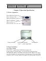
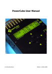
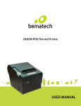
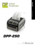
2.1 Printer Appearance
Power Indicator (green)
Status Indicator (red)
Paper-end Indicator (red)
Paper Feed Button(feed)
Paper-out Slot
Power Switch
Printer interface
Cash drawer interface
Power socket
Fig.2-1 printer appearance
2.2 Paper Installation
2.2.1 Paper Loading
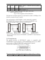
SP-POS88Ⅳ adopts 80mm width thermal paper roll.
If you prepare to load the paper, you can do as the following steps.
Hold down the upper cover button, open the movable upper cover, move
away the old paper roll, and put the new thermal paper in the paper holder
of printer, draw a certain length of the paper roll, put the paper end on the
6
print head, close the upper cover and press it downwards lightly until it
restore to original position, and the paper end appears from the paper-out
slot which is on the upper cover, then print paper installation is finished.
Caution!
1. When there is no paper in the print head, don’t press 【FEED】
button, avoiding to shorten the print head life;
2. Please don’t feed or draw the paper forwards or backwards with
hands. When returning paper, please cut the extra paper, and press
【LF】button, paper will go forwards.
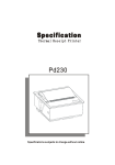
2.2.2 Solution to Paper Jam
Turn power off, open the upper cover, hold down the black rubber cutter
lever, at the same time move the cutter forwards slowly, can separate the
cutter from the print head. Then lift the print head lever forwards to
maximum position, draw out the paper slowly with hand.
2.3 Interface
2.3.1 Serial Interface
The serial interface of SP-POS88Ⅳ printer is compatible with RS-232C,
supports RTS/CTS and XON/XOFF handshaking protocols, uses DB25
socket (female). The pin order of the serial port is as Fig.2-2 shows:
13
25
1
14
Fig.2-2 Pin Order of Serial Port
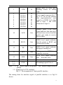
The pin assignment of serial interface is shown in Fig. 2-3:
Pin Signal Source
Description
No. Name
2
RXD
Host Printer receives data from host
3
TXD Printer Printer transmits control code X-ON/X-OFF
and data to host
5
CTS
Printer Signal “MARK” indicates that the printer is
“BUSY” and unable to receive data; “SPACE”
indicates that the printer is “READY” for
receiving data.
7
6
DSR
Printer Signal “SPACE” indicates that the printer is
“ONLINE”
7
GND
—
Signal Ground
8
DCD Printer Same to signal CTS
Note: ①“Source” denotes the source that signal come from;
② Logical signal level is EIA.
Fig.2-3 Pin Assignment of Serial Interface
The baud rate and data structure in serial interface mode is 9600bps, 8-bit
data bits, no parity bit and 1 stop bit.
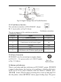
The serial interface of SP-POS88Ⅳ can be connected to standard
RS-232CRS-232C interface. When it is connected to IBM PC or its
compatible machine, connection can accord to Fig.2-4.
DSR 6
GND 7
RTS 5
6 DSR
DSR 6
6 DSR
5 GND
G ND 7
R TS 5
7 GND
T XD 3
R XD 2
8 DCD
8 CTS
TXD 3
RXD 2
1 DCD
2 RXD
3 TXD
5 CTS
3 RXD
2 TXD
Printer
IBM PC Serial Printer
IBM PC Serial
25PIN Socket Interface DB-9
25PIN Socket
Interface DB-25
Fig.2-4 Connection between SP-POS88Ⅳ and IBM PC Serial Interface
Sketch Map
2.3.2 Parallel Interface
The parallel interface of SP-POS88 Ⅳ printer is compatible with
CENTRONICS, supports BUSY or ACK handshaking protocol, uses DB25
socket (male) or 36pin CENIRONICS socket (female) optional.
The pin order of parallel port is as Fig. 2-5 shows:
Fig.2-5 Pin Order of Parallel Port
The pin assignment of DB25 parallel interface is shown in Fig. 2-6 shows:
Pin No.
Signal
Direction
Description
8
1
/STB
In
2
3
4
5
6
7
8
9
DATA1
DATA2
DATA3
DATA4
DATA5
DATA6
DATA7
DATA8
In
In
In
In
In
In
In
In
10
/ACK
Strobe pulse to latch data,
Reading occurs at falling edge.
These signals represent the 1st
bit to 8th bit of the parallel data
representatively, each signal is
at HIGH level when data is
logic 1, and LOW when data is
logic 0.
Out
Answer pulse, LOW level
signal indicates that data have
already been received and the
printer gets ready to receive the
next data.
11
BUSY
Out
HIGH level signal indicates that
the printer is BUSY and can not
receive data.
12
PE
Out
HIGH level signal indicates that
paper is end.
13
SEL
Out
Pulling up to HIGH level signal
by a resistor
15
/ERR
Out
LOW level signal indicates that
there has error.
14,16,17
NC
---
No connection
18-25
GND
---
Grounding logical 0 level
Note: (1)“In” denotes input to the printer,“Out” denotes output from the
printer.
(2)Signal level is TTL standard.
Fig.2-6 Pin assignment of DB-25 parallel interface
The pin assignment of 36pin parallel interface is as Fig.2-7 shows:
pin No.
Signal
Direction
Description
9
1
/STB
In
2
3
4
5
6
7
8
9
DATA1
DATA2
DATA3
DATA4
DATA5
DATA6
DATA7
DATA8
In
In
In
In
In
In
In
In
10
/ACK
Strobe pulse to latch data,
Reading occurs at falling
edge.
These signals represent the 1st
bit to 8th bit of the parallel
data representatively, each
signal is at HIGH level when
data is logic 1, and LOW
when data is logic 0.
Out
Answer pulse, LOW level
signal indicates that data have
already been received and the
printer gets ready to receive
the next data.
11
BUSY
Out
HIGH level signal indicates
that the printer is BUSY and
can not receive data.
12
PE
Out
HIGH level signal indicates
that paper running out.
13
SEL
Out
Pulling up to HIGH level
signal by a resistor
32
/ERR
Out
LOW level signal indicates
that there has error.
14, 15, 17, 18, 34, 36
NC
--No connection
16, 19~
GND
--Grounding logical 0 level
30, 33
Note: (1)“In” denotes input to the printer,“Out” denotes output from the
printer.
(2)Signal level is TTL standard.
Fig. 2-7 Pin assignment of 36pin parallel interface
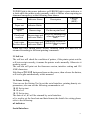
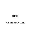
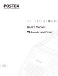
The timing chart for interface signal of parallel interface is as Fig.2-8
shows:
10
BU SY
/A CK
DA TA
/S TB
0. 5μS
0. 5μS
0. 5μS
0. 5μS
0. 5μS
Fig.2-8 Signal Timing Chart of Parallel Interface
2.3.3 Cash Drawer Interface
The cash drawer interface of POS-POS88Ⅳ adopts
RJ-11 6-pin socket, as Fig.2-9 shows:
Fig. 2-9
Cash drawer interface
The pin assignment of the cash drawer interface
is defined as follows:
Pin No.
Signal
Direction
1
Chassis Ground
--2
Cash drawer driver signal
Out
3
Cash drawer on/off status signal
In
4
5
+24VDC
N.C
Out
---
6
Cash drawer on/off status signal ground
---
2.3.4 Power Connection
SP-POS88Ⅳ uses the external power supply adopter
as 24V±10%、2A, power socket is A-1009-3P model,
as Fig. 2-10 shows:
2
3 1
Fig.2-10
Power Socket
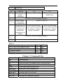
2.4 Buttons and Indicators
There is one button and three indicators on SP-POS88Ⅳ printer. 【FEED】
is paper feeding button, the function of its enabling or disabling the button
on/off can be set by print command, when the button is enabled, press
【FEED】 button, then the paper presenting driver starts up and paper fed
into the printer; release【FEED】 button, paper feeding stops. The green
11
POWER light is the power indicator, red ERROR light is status indicator, it
is dark when the printer works normally, while it flashes when reporting an
abnormal emergency, as the following form shows:
ERROR
Error
Indicator Status
Description
Code
(HEX)
Paper out
Indicator blinks
Print head
uplift
Buzzer rings
Print head
overheat
Put down print head
automatically
Buzzer rings and Recovers
when
the
print head
indicator blinks
cools.
Auto cutter Buzzer rings and
Position Error indicator blinks
Impossible to recover,
check if there is paper
jam.
When any error shown above occurs, different status and data will be
returned according to different printing commands.
2.5 Self-test
The self-test will check the condition of printer, if the printer prints out the
self-test receipt correctly, it means the printer works normally. Otherwise it
needs to repair.
The self-test will print out the firmware version, interface setting and 128
ANK characters.
Hold down【FEED】button and turn on the power, then release the button,
self-test begins automatically at this moment.
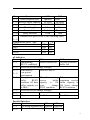
2.6 Printer Setting
User can use the Setting Tool to set the serial interface, printing density etc.
parameters, also can use the following commands to set:
1B 09 Set to start
1B 10 n1 n2
1B 15 Set to stop
The data of n1, n2 will be returned by serial interface.
n1 is used to set the baud rate and data format, the details for setting please
refer to the following:
n1 indicates:
Serial Interface:
12
Bit
Function
ON
OFF
Ignored
1-1 Data reception error
Print “?”
45 bytes
4K bytes
1-2 Receive buffer capacity
Handshaking
XON/XOFF DTR/DSR
1-3
Word length
7 bits
8 bits
1-4
Parity check
Enabled
Disabled
1-5
Parity selection
Even
Odd
1-6
1-7 Transmission speed (refer to the following table)
1-8
Transmission speed(bps)
1-7 1-8
38400
ON ON
4800
OFF ON
9600
ON OFF
19200
OFF OFF
n2 indicates:
Bit
Function
ON
Receive buffer full
2-1 Handshaking
(BUSY condition)
2-2 Reserved (Do not change settings)
Refer to Table A
2-3 Print density /
2-4 Low power
consumption
receive When the remaining
2-5 Change
buffer
BUSY receive
buffer
condition (If data capacity is 138
buffer capacity set bytes,
change
to 4KB.)
BUSY condition.
2-6 Reserved (Do not change settings)
2-7
Enabled
2-8 0D print
OFF
Off line or receive
buffer full
When
the
remaining receive
buffer capacity is
256 bytes, change
BUSY condition.
Disabled
Parallel Interface
Bit
Function
ON
OFF
Go along automatically Enabled Disabled
1-1
Receive buffer capacity 45 bytes 4K bytes
1-2
13
1-3~1-8 Undefined
Bit
2-1
Function
Handshaking
(BUSY
condition)
ON
Receive buffer full
OFF
Off line or receive
buffer full
Reserved (Do not change settings)
Print density /
Refer to Table A
Low power
consumption
When the remaining
2-5 Change receive When the remaining
buffer BUSY receive buffer capacity receive buffer capacity
condition (If
is 138 bytes, change
is 256 bytes, change
data buffer
BUSY condition.
BUSY condition.
capacity set to
4KB.)
Reserved (Do not change settings)
2-6~
2-7
On, 0x0d enabled
2-8
2-2
2-3
2-4
Table A
Print density / Low power consumption
- Low power consumption mode
1 Normal density
2 Medium density
3 High density
SW 2-3
ON
OFF
ON
OFF
SW 2-4
ON
OFF
OFF
ON
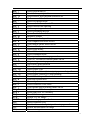
Chapter 3 Command List
Command
HT
LF
FF
CR
CAN
DLE EOT
DLE ENQ
DLE DC4
ESC FF
ESC SP
Name
Horizontal tab
Print and line feed
Print and return to standard mode (in page mode)
Print and carriage return
Cancel print data in page mode
Real-time status transmission
Real-time request to printer
Generate pulse at real-time
Print data in page mode
Set right-side character spacing
14
ESC !
ESC $
ESC %
ESC &
ESC *
ESC ESC 2
ESC 3
ESC =
ESC ?
ESC @
ESC D
ESC E
ESC G
ESC J
ESC L
ESC M
ESC S
ESC T
ESC V
ESC W
ESC \
ESC a
ESC c 0
ESC c 3
ESC c 4
ESC c 5
ESC d
ESC p
ESC t
ESC {
FS g 1
FS g 2
FS p
FS q
GS FF
GS !
GS $
GS *
GS (
Select print mode(s)
Set absolute print position
Select/cancel user-defined character set
Define user-defined characters
Select bit-image mode
Turn underline mode on/off
Select default line spacing
Set line spacing
Select peripheral device
Cancel user-defined characters
Initialize printer
Set horizontal tab positions
Turn emphasized mode on/off
Turn double-strike mode on/off
Print and feed paper
Select page mode
Select character font
Select standard mode
Select print direction in page mode
Turn 90° clockwise rotation mode on/off
Set printing area in page mode
Set relative print position
Select justification
Select paper type
Select paper sensor(s) to output paper-end signals
Select paper sensor(s) to stop printing
Enable/disable panel buttons
Print and feed n lines
General pulse
Select character code table
Turn upside-down printing mode on/off
Write to user NV memory
Read from user NV memory
Print NV bit image
Define NV bit image
Black mark paper localization
Select character size
Set absolute vertical print position in page mode
Define downloaded bit image
Execute test print
15
Print downloaded bit image
Start/end macro definition
Turn white/black reverse printing mode on/off
Select printing position of HRI characters
Transmit printer ID
Set left margin
Set horizontal and vertical motion units
Cut paper
Set printing area width
Set relative vertical print position in page mode
Ignored
Execute macro
GS ^
Enable/disable Automatic Status Back (ASB)
GS a
Turn smoothing mode on/off
GS b
Select font for HRI characters
GS f
Set bar code height
GS h
Print bar code
GS k
Transmit status
GS r
Print raster bit image
GS v 0
Set bar code width
GS w
Set print mode(s) for Chinese characters
FS !
Select Chinese character mode
FS &
Turn underline mode on/off for Chinese characters
FS –
Cancel Chinese character mode
FS .
Define user-defined Chinese characters
FS 2
Set left- and right-side Chinese character spacing
FS S
Turn quadruple-size mode on/off for Chinese
FS W
characters
Detailed command description please refer to 《SP-POS88IV Control
Commands》.
GS /
GS :
GS B
GS H
GS I
GS L
GS P
GS V
GS W
GS \
16
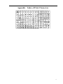
Appendix
Index of Print Characters
17