1
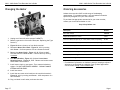
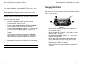
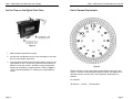
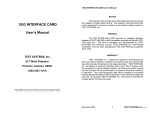
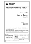
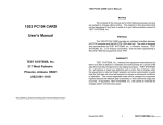
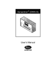
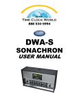
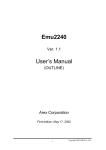
r
2000 - 4000 Series
User’s Guide
Printed in USA
P/N: OMOV0605A
2000 – 4000 Series Time Recorder User’s Guide
Warranty
Contents
Here’s all the information you need for setting and operating your new
Lathem time recorder. Service information is also included in this
manual, in case any problems ever arise.
One-Year Limited Warranty
Lathem warrants the hardware products described in this guide against defects in
material and workmanship for a period of one year from date of original purchase from
Lathem or from an authorized Lathem reseller. The conditions of this warranty and the
extent of the responsibility of Lathem Time Corporation (“Lathem”) under this warranty
are listed below.
Thank you for choosing a Lathem time recorder. Should you ever need
assistance, please let us know.
1.
Ordering Accessories ........................................................1
Setting the Time................................................................2
Changing the Ribbon.........................................................9
Replacing the Type Section...........................................10
Install / Replace Batteries in BATT .............................11
Changing the Motor.........................................................12
Warranty ...........................................................................13
3.
2.
4.
5.
6.
7.
8.
9.
This warranty will become void when service performed by anyone other than
an approved Lathem warranty service dealer results in damage to the product.
This warranty does not apply to any product which has been subject to abuse,
neglect, or accident, or which has had the serial number altered or removed,
or which has been connected, installed, adjusted, or repaired other than in
accordance with instructions furnished by Lathem.
This warranty does not cover dealer labor cost for removing and reinstalling the
machine for repair, or any expendable parts that are readily replaced due to
normal use.
The sole responsibility of Lathem under this warranty shall be limited to repair
of this product, or replacement thereof, at the sole discretion of Lathem.
If it becomes necessary to send the product or any defective part to Lathem or
any authorized service dealer, the product must be shipped in its original
carton or equivalent, fully insured with shipping charges prepaid. Lathem will
not assume any responsibility for any loss or damage incurred in shipping.
WARRANTY DISCLAIMER AND LIMITATION OF LIABILITY: Except only the limited
express warranty set forth above, the products are sold with no expressed or
implied warranties of any kind, and the implied warranties of merchantability
and fitness for a particular purpose are hereby expressly disclaimed. No
warranties are given with respect to products purchased other than from
Lathem or an authorized Lathem reseller and any such products are purchased
“as is, with all faults.” In no event will Lathem be liable for any direct, special,
or consequential damages arising out of or in connection with the delivery, use
or inability to use, or performance of this product. In any event any limited
remedy given herein shall be deemed to have failed of its essential purpose,
Lathem’s maximum liability shall be to refund the purchase price upon return
of the product.
Proof of date of purchase from Lathem or an authorized Lathem reseller is
required for warranty service on this product.
This Warranty grants specific legal rights. Additional legal rights, which may
vary by locale, may also apply.
Should any difficulties arise with the performance of this product during
warranty, or with any Lathem authorized service centers, contact Lathem Time
at the address below.
Lathem Time Inc
200 Selig Drive, SW, Atlanta, GA 30336
404-691-0405
www.lathem.com
Page 13
2000 – 4000 Series Time Recorder User’s Guide
Changing the Motor
2000 – 4000 Series Time Recorder User’s Guide
Ordering Accessories
Lathem time recorders fulfill a wide range of timekeeping
requirements. For maximum results, only use Lathem accessories
specifically designed to fit your time recorder.
To purchase the appropriate accessories for your time recorder,
contact your local Lathem dealer or visit:
http://shop.lathem.com
Description
Part
Number
Extra Pair of Keys
VSM0976
Replacement Ribbon, 2-Colors
7-2CN
Time Card Rack, 25 Capacity, 9” Card, Black, Plastic, Expanding
25-9EX
Time Card Rack, 12 Capacity, 9” Card, Black, Plastic, Expanding
12-9EX
3. Figure 10 shows a close-up of cam block terminal.
Time Cards, Weekly (Box of 1,000)
1900L-C
4. Disconnect Motor Wire Leads – Figure 10, 10.1 by turning
each Screw – 10.2 one-quarter of a turn counterclockwise.
Time Cards, Bi-Weekly (Box of 1,000)
L-31-1D
5. Remove the Motor Clutch – Figure 10, 10.3 from its shaft.
The shaft has LEFT HAND threads – remove clutch by turning
clockwise.
Time Cards, Semi-Monthly / Monthly (Box of 1,000)
1790
Time Cards, Job Costing (Box of 1,000)
350
6. Hold Motor Bracket – Figure 10, 10.4 and loosen Motor
Mounting Screws – Figure 10, 10.5. Remove and retain screws
and bracket from old motor.
Replacement Timing Motor, 110V/60Hz
K342
Figure 10
1. Unplug cord from wall outlet (except 2100BATT).
2. Remove type section from main frame (see “Replacing the Type
Section”).
7. Install motor clutch on new motor. Turn counterclockwise to
tighten. DO NOT OVERTIGHTEN OR BEND – YOU MAY DAMAGE
INTERNAL MOTOR GEARS.
* For additional information on Lathem’s powerful employer software
solutions or to download an evaluation copy of these applications
visit us online at http://www.lathem.com.
8. Install new motor.
9. Install the new motor wire leads into the cam block terminal –
Figure 10, 10.1 by turning each Screw – 10.2 one-quarter of a
turn clockwise.
10. Plug cord back in wall outlet, and reset the time.
Page 12
Page 1
2000 – 4000 Series Time Recorder User’s Guide
Setting the Time
2000 – 4000 Series Time Recorder User’s Guide
Install / Replace Batteries in BATT
Figure 1
Determine Your Model
Before proceeding, it is important to know the exact model of your
clock so it can be set properly. The fourth digit in the model number
indicates the print format.
Description
Figure 9
The 2000-BATT requires four “D” size batteries and should operate
for six months before replacement. An internal beeper sounds
momentarily each minute when the battery supply discharges
below 4.5 volts. Replace batteries as follows when this occurs:
Model
Print Hours
Print Units
xxx1
1 – 12 , 1 – 12
00 – 59
12 Hour & Minutes
xxx2
1 – 12 , 1 – 12
.0 – .9
12 Hour & Tenths
xxx3
1 – 12 , 1 – 12
.00 – .98
xxx4
00 – 23
00 – 59
24 Hour & Minutes
1. Pull and remove the front two rubber feet underneath the unit.
xxx5
00 – 23
.0 – .9
24 Hour & Tenths
xxx6
00 – 23
.00 – .98
2. Loosen, 1 to 2 turns, the two phillips-head screws located 1.5
inches directly inside the rubber feet mounting holes.
12 Hour & Hundredths
24 Hour & Hundredths
3. Slide the bottom battery compartment outward (to front) and
down, to get to the batteries. (See Figure 9.)
Example: Since the fourth digit in the model number 2104 is a “4”, it
will print with 00-59 minutes and 00-23 hours (see table above). The
model number is located on the Label 1.1 positioned as shown in
Figure 1.
Page 2
4. Replace the four “D” size batteries. Be sure the batteries are
installed with proper polarity (+/-) as marked on battery holder.
5. Re-install the battery compartment on the bottom of the
recorder, aligning the holes with the screws.
Press the
compartment firmly to the back (inward), tighten the two
Phillips-head screws, and re-insert the two rubber feet.
Page 11
2000 – 4000 Series Time Recorder User’s Guide
Replacing the Type Section
2000 – 4000 Series Time Recorder User’s Guide
Raise the Type Section
1. Unlock the case cover and pull it forward to remove it.
If your type section needs servicing, you can easily remove and replace
it without sending the entire machine for service.
2. Note the position of the Release Latch and Face Setting Wheel
used later in this process.
3. Wait until you hear the clock “click”.
4. Press either side of the Type Section Headlock – Figure 1, 1.2
and pull upward on the lower part of the Clock Face until the
Type Section locks in the up position as shown in Figure 1.
Note position of the Overthrow Lever and the Setting Wheel.
5. Press the red Overthrow Lever – Figure 1, 1.3 away from you
until it clicks. This releases the wheels allowing them to turn.
Set the Time on the Type Wheels
Figure 8
1. Remove the top cover.
2. Remove Type Section Retaining Ring and Washer– Figure 8,
8.1.
3. If the type section has digital time display, unplug connectors
(not shown).
4. Lift type section slightly and move it to the right to release
Hinge Pins – Figure 8, 8.2 from their sockets. The Type
Section will lift out.
Figure 2
1. Locate the Center Line where all the wheels line up as shown in
Figure 2.
2. Rotate the wheels using a pointed object. Rotate each wheel
until the correct date and time are aligned at the Center
Position, as shown in Figure 2. Hint: Start at the top wheel
and work down when setting.
Page 10
Page 3
2000 – 4000 Series Time Recorder User’s Guide
If your model prints Tenths, (models with the 4th digit of 2 or 5), go to
the section “Setting Decimal Wheel with Tenths”.
If your model prints Hundredths or 00-23 hours, refer to the Dial of
Decimal Equivalents in Figure 3 (page 6) to determine the correct
setting.
2000 – 4000 Series Time Recorder User’s Guide
Changing the Ribbon
Lathem time recorders have self-reversing ribbons. With normal use, a
ribbon should last for many months or even years….and when the time
comes, it is easy to change.
Note: if your machine records in 1-12 hours, the PM hours are
underlined. AM hours are not underlined. Set time to the proper hour
of the day to avoid errors such as setting the day wheel to the next
day at noon rather than midnight.
3. Rotate the Minute Wheels to show the current minute.
4. Set the Hour Wheel to the current hour
5. Rotate the Clock Face Setting Wheel – Figure 5.1 on page 8,
to set the hands to match the time set on the wheels.
6. Rotate the Main Setting Wheel – Figure 2, 2.1 to advance both
the Clock Face and Print Wheels together. Rotate until you
pass the actual time by one minute (each “click” indicates one
minute.)
7. Hold the corner of the Clock Face and release the Release
Latch – Figure 2, 2.2 by pushing it to the left. Slowly let the
Type Section down and press it firmly into the Type Section
Headlock.
8. Make a sample registration and verify the time and date or day
is correct.
9. Replace and lock the case cover.
Note: The month wheel and the date wheel must be reset manually at
the beginning of each month.
Page 4
Figure 7
1. Remove the top cover and raise type section (see “Raise the
type section” on page 4.)
2. Remove the cotter pins – Figure 7, 7.1 that retain the ribbon
spools and slide off old spools.
3. Lift ribbon hold-down guide – Figure 7, 7.2 – use a pencil to
support it in an up position.
4. Remove ribbon and replace with new Lathem ribbon. Make
sure the ribbon feeds from bottom of the spools and runs
BETWEEN reversing fingers – Figure 7, 7.3, the red side should
be aligned with the date or day wheel(s).
5. Install cotter pins; remove pencil, and lower the type section
into place.
Page 9
2000 – 4000 Series Time Recorder User’s Guide
Set the Time on the Digital Clock Face
2000 – 4000 Series Time Recorder User’s Guide
Dial of Decimal Equivalents
Figure 6
1. Make a sample registration on paper.
2. Use the Hour and Minute buttons to set the display to the time
shown on the sample registration.
3. To synchronize the display with the type wheels, listen for the
type wheels to click. At the click, press the minute button to
advance to the next minute. Seconds are now synchronized.
Always set the display to regular minutes. Refer to Figure 3,
“dial of decimal equivalent” if wheels print in hundredths or
tenths.
Figure 3
The dial in Figure 3 shows the tenths and hundredths setting for each
minute. The inner circle represents regular minutes, the middle circle
represents tenths, and the outer circle represents hundredths of a
minutes.
For example:
45 minutes = .7 tenths = .75 hundredths
Page 8
Page 5
2000 – 4000 Series Time Recorder User’s Guide
Setting Decimal Wheel with Tenths
2000 – 4000 Series Time Recorder User’s Guide
Set the Time on the Analog Clock Face
Figure 4
Use only for recorders printing in tenths
(models with a 4th digit of “2” or “5”)
1
Rotate Tenths Wheel (0.9)–
Figure 4, 4.1 until it is set at
“9” Rotate the Main Setting
- Figure 4, 4.3 until the
Tenths Wheel moves to a “0”.
(This is the zero minute.)
2. Set the Hour Wheel – Figure 4,
4.2 to the current Hour.
3. Rotate the Clock Face Setting
Wheel – Figure 5, 5.1 to set the
hands to match the time set on
the wheels.
Figure 5
1. Make a sample registration on paper.
2. Rotate Clock Face Setting Wheel 5.1 until the clock face
displays the same time as shown on the sample registration.
DO NOT TURN THECLOCK HANDS EXCEPT BY USING THE
SETTING WHEEL – Figure 5, 5.1.
4. Rotate the Main Setting Wheel – Figure 4, 4.3 to advance both
the Clock Face and Print Wheels together. Rotate until you
pass the actual time by one minute (each “click” indicates one
minute.)
For example, at 10:05, rotate 5 times = 5 clicks = 5 minutes
past ten o’clock.
5. Hold the corner of the Clock Face and release the Release
Latch by pushing it to the left. Slowly let the Type Section
down and press it firmly into the Type Section Headlock.
6. Make a sample registration and verify the time and date or day
is correct.
7. Replace and lock the case cover
Page 6
Page 7