1
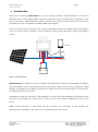
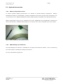
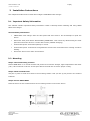
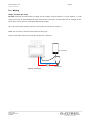
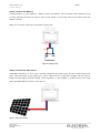
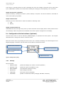
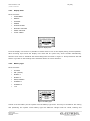
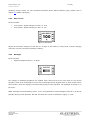
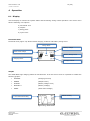
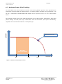
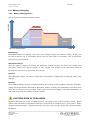
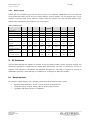
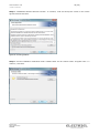
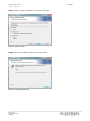
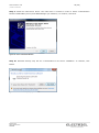
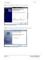
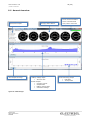
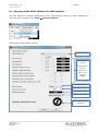
UKKO MPPT-10 /USER MANUAL Document Version 1.1 Electriel Ltd © All Rights Reserved Finland UKKO MPPT-10 1 (29) /USER MANUAL Table of Contents 1 Introduction ......................................................................................................................... 2 2 Product Features .................................................................................................................. 3 3 4 5 6 2.1 Product Overview ......................................................................................................... 3 2.2 Technical Specifications................................................................................................. 4 2.3 Optional Accessories ..................................................................................................... 5 Remote Temperature Sensor .......................................................................... 5 2.3.2 UKKO Manager (PC Software) ......................................................................... 5 Installation Instructions ......................................................................................................... 6 3.1 Important Safety Information ........................................................................................ 6 3.2 Mounting ..................................................................................................................... 6 3.3 Wiring ......................................................................................................................... 7 3.4 Configuration Via Device Menu (Optional)........................................................................ 9 3.4.1 Settings ....................................................................................................... 9 3.4.2 Display View............................................................................................... 10 3.4.3 Battery Type .............................................................................................. 10 3.4.4 Max Current ............................................................................................... 11 3.4.5 Backlight.................................................................................................... 11 3.4.6 Language ................................................................................................... 12 3.4.7 Charging .................................................................................................... 12 Operation .......................................................................................................................... 13 4.1 Display ..................................................................................................................... 13 4.2 Maximum Power Point Tracking .................................................................................... 15 4.3 Battery Charging ........................................................................................................ 16 4.3.1 Battery Charging Modes ............................................................................... 16 4.3.2 Battery types.............................................................................................. 17 PC Software ....................................................................................................................... 17 5.1 Requirements ............................................................................................................ 17 5.2 Installing the UKKO Manager ....................................................................................... 18 5.3 Launching the UKKO Manager ...................................................................................... 24 5.4 Connecting UKKO MPPT to the Computer ....................................................................... 24 5.5 General Overview ....................................................................................................... 25 5.6 Changing UKKO MPPT Settings via UKKO Manager.......................................................... 26 Troubleshooting.................................................................................................................. 27 6.1 7 2.3.1 Protections ................................................................................................................ 28 Warranty ........................................................................................................................... 29 Electriel Ltd www.electriel.com FINLAND UKKO MPPT-10 2 (29) /USER MANUAL 1 Introduction Thank you for choosing UKKO MPPT for your solar charge controller! The UKKO MPPT is an advanced Maximum Power Point Tracking (MPPT) technology using solar charge controller that is designed for easy plug n’ play usage. MPPT technology helps to maximize the energy production and it can increase the production up to 25 % compared to standard PWM solar chargers. Large touch screen user panel gives easy access to information about the installed solar energy system. Use it to monitor battery condition, energy production, battery and solar panel voltage and charging current. USB CHARGING SOLAR PANEL DC INPUT FUSE DC OUTPUT FUSE BATTERY Figure 1. System Overview UKKO Manager PC Software is used to configure and customize the settings of UKKO MPPT. It features visual presentation of the system data and gives you further control over the energy production. UKKO Manager is available free of charge from Electriel’s website and can be used with any PC via USB cable. No additional accessories required UKKO MPPT is made for easy plug n’ play installation. To have clear understanding of the benefits of the controller we encourage you to take time to read this user manual before installation and use of the device. NOTE: Product warranty is void should you fail to follow the instructions of this manual! The manufacturer is not liable for any harm or lose caused by misuse of the device. Electriel Ltd www.electriel.com FINLAND UKKO MPPT-10 3 (29) /USER MANUAL 2 Product Features 2.1 Product Overview 5 4 1 3 2 Figure 2. UKKO MPPT Main Parts 1. Power Screw Terminal Power terminations for solar, battery and load. 2. USB Connector for Mobile Charging Mobile devices can be charger directly via this USB connector. 3. Temperature Sensor Connector Connection for optional remote battery temperature sensor. 4. USB Connector for PC This USB connector provides connection to PC. UKKO Manager PC software can be downloaded from Electriel’s website for more careful monitoring of your solar system. 5. Touch Screen In operation mode the display shows graphs of energy production, battery voltage, solar panel voltage, current, power and battery charge state. Touch the display briefly to turn on the backlight. Backlight will turn off automatically after one minute. Touch the screen for 5 seconds to enter the menu. Electriel Ltd www.electriel.com FINLAND UKKO MPPT-10 4 (29) /USER MANUAL 2.2 Technical Specifications ELECTRICAL Nominal battery Voltage: Max. Battery Voltage: Nominal Charging Current: Max. Solar Panel Voltage: Nominal Max. PV input: Peak Efficiency: USB Output Max. Current: Load Output Max. Current: 12 / 24 Volts (Auto Detect) 16 / 32 Volts 10 / 5 Amps 75 Volts 200 W 97 % 500 mA 20 A ENVIRONMENT Operating Temperature: Storage Temperature: Humidity: –15 °C to +60 °C –20 °C to +70 °C 90 % non-condensing ELECTRONIC PROTECTION Solar Panel Over Load Solar Panel Over Voltage Battery Reverse Polarity Battery Over Voltage High Heat Sink Temperature High Battery Temperature Lightning and other transients Reverse Current at Night PHYSICAL Dimensions: Weight: Mounting: Materials: Protection Standard: Screw Terminals: USB Connectors: 115 mm x 126mm 370 g 4 x 5 mm mounting holes Plastic /die cast aluminium IP20 Max. 20 mm2 / 6 AWG Type A and Type B BATTERY CHARGING Battery Types: Charging Modes: Temperature Compensation: Compensation Range: Gel, Sealed, AGM, Flooded, Custom Bulk/Boost, Absorption, Float, Equalize (optional) -5mV/°C/Cell (or adjustable) -30 °C to +60 °C CONFORMANCE This device Meets requirements for CE marking. Conform the following directives EMC Directive: 2004/108/EC RoHS Directive: 2002/95/EC WEEE Directive: 2002/96/EC LVD Directive: 2006/95/EC According to following relevant standards Immunity: IEC61000-6-2:2005 Emissions: IEC61000-6-2:2006 Safety: EN60335-1 and EN60335-2-29 Electriel Ltd www.electriel.com FINLAND UKKO MPPT-10 5 (29) /USER MANUAL 2.3 Optional Accessories 2.3.1 Remote Temperature Sensor To achieve optimal charging performance it is advised to measure battery temperature. Battery temperature should be compensated, if battery temperature varies from normal room temperature (20 °C) more than ±5 °C. Battery temperature sensor (model: BTS10) is available as an optional accessory. Battery temperature sensor can be installed at any time. UKKO MPPT will automatically recognize the sensor and activate it. Standard cable length is 5 m (16.7 ft) but it can be extended up to 30 m (100 ft). Figure 3. Battery Temperature Sensor (Model: BTS10) 2.3.2 UKKO Manager (PC Software) The UKKO Manager PC software is available free of charge from Electriel’s website. Use it to monitoring your solar system or modify the settings of the device. For more information see page 18. Electriel Ltd www.electriel.com FINLAND UKKO MPPT-10 6 (29) /USER MANUAL 3 Installation Instructions This chapter describes how to install and configure UKKO MPPT solar charger. 3.1 Important Safety Information This manual contains important safety information. Read it carefully before installing and using UKKO MPPT solar charger. General Safety Information UKKO MPPT solar charger does not have parts that need service. Do not attempt to repair the device. Disconnect solar panel before disassembling UKKO MPPT. This is done by disconnecting the solar panel wires from the device or via the device menu (Disable Charging). Confirm that power connections polarity is correct. Confirm that power connections are tightened to avoid loose connections from causing excessive heating. Protect the device from water and moisture. 3.2 Mounting Step 1: Choose Mounting Location Install UKKO MPPT on a vertical surface and protect it from direct sunlight, high temperatures and water (rain). Have minimum of 20 cm of free space above the heat sink to ensure proper cooling. Step 2: Mark and Drill holes Use pen or pencil to mark four holes to the mounting surface. Drill 2,5 mm (3/32”) holes in the marked locations. Step 3: Secure UKKO MPPT Place the device on the surface and use four mounting screws to secure the device. Figure 4. Mounting the UKKO MPPT Electriel Ltd www.electriel.com FINLAND UKKO MPPT-10 7 (29) /USER MANUAL 3.3 Wiring Step 1: Connect the Load DC OUT connector provides battery voltage for the system. Connect positive (+) and negative (-) load wires to the load or load distribution panel and DC OUT connector. An USB load can be plugged at this point and it can be used as a standard USB charger output. An in-line fuse holder should be wired in series with load as shown in figure 5. NOTE: Do not insert a fuse into fuse holder at this point! Load current draw cannot exceed 20 A from DC OUT connector. USB CHARGING FUSE 25 A Figure 5. Load Circuit Electriel Ltd www.electriel.com FINLAND DC OUTPUT UKKO MPPT-10 8 (29) /USER MANUAL Step 2: Connect the Battery Connect positive (+) and negative (-) battery wires to the battery. An in-line fuse holder should be wired in series with load as shown in figure 6. Wire a fuse holder no more than 150 mm (6 inches) from the battery terminal. NOTE: Do not insert a fuse into fuse holder at this point! FUSE 25 A BATTERY Figure 6. Battery Circuit Step 3: Connect the Solar Panel UKKO MPPT accepts 12 V, 24 V or 36 V nominal voltage off-grid solar arrays. If grid-tie solar modules are used, solar panel open circuit voltage (Voc) can be maximum 75 V. Solar panel voltage must be equal or bigger than the battery nominal voltage. Connect positive (+) and negative (-) battery wires to the solar panel and UKKO MPPT as shown in the figure 6. SOLAR PANEL DC INPUT Figure 7. Solar Panel Circuit Electriel Ltd www.electriel.com FINLAND UKKO MPPT-10 9 (29) /USER MANUAL If the device is already turned on after connecting the wires and voltage is detected in the solar panel input, UKKO MPPT will wait 30 seconds before starting the charging to avoid sparking in the connector. Step 4: Accessories (optional) Install the Battery Temperature Sensor (model: BTS10) if required. The sensor should be mounted as close to the battery as possible. Step 5: Install Fuses Install 25…30 A DC rated fuses in each fuse holders in following order: 1. Load 2. Battery Step 6: Confirm Power-up UKKO MPPT should now begin the power-up. Check from the device display that is shows product name on the display. After the splash screen statistics of the solar system will appear on the display. 3.4 Configuration Via Device Menu (Optional) Use the device menu or the PC software (UKKO Manager) to optimize the solar system. This chapter describes how to configure the device via device menu. Enter the device menu by pressing the touch screen for 5 seconds. Following view should appear when English language is selected. Use the touch screen buttons to browse the menu. Previous menu / Exit menu Scroll menu up and down Enter to selected menu / Accept settings Location in the menu Figure 8. Settings Menu (Root) 3.4.1 Settings Menu selections DISPLAY VIEW (Select the display view mode in normal operation) BATTERY TYPE (Select the type of the battery in use) MAX CURRENT (The Maximum charging current) BACKLIGHT (Set backlight intensity) LANGUAGE (Choose the device language) CHARGING (Enable or Disable the battery charging and MPPT controller) Electriel Ltd www.electriel.com FINLAND UKKO MPPT-10 10 (29) /USER MANUAL 3.4.2 Display View Menu selections FUNCTIONAL ENERGY CURRENT POWER CHARGE STAGE BATTERY VOLTAGE PANEL VOLTAGE CYCLE VIEWS Figure 9. Display View From the display view menu it is possible to choose what to view on the display during normal operation. When choosing Cycle Views the display view mode will be cycled every three seconds automatically. Selected view mode is indicated with black background as shown in figure 9. Accept selection with OK button or go back to the Settings menu with back button on cancel selection. 3.4.3 Battery Type Menu selections CUSTOM GEL (default) SEALED 1 SEALED 2 AGM/FLOODED FLOODED 1 FLOODED 2 L-16 Figure 10. Battery type Choose a correct battery for the system from the battery type menu. This may be needed for fine tuning and optimizing the system. Each battery type has different voltage limits for boost, floating and Electriel Ltd www.electriel.com FINLAND UKKO MPPT-10 11 (29) /USER MANUAL equalizing charge modes. For more detailed information about different battery types, please refer to chapter 4.3 (Battery Charging). 3.4.4 Max Current Menu selections 12 V System: Adjust Charging current 0.5…10 A 24 V System: Adjust Charging current 0.5…5 A Figure 11. Max Current Adjust the maximum charging current with 0.1 A steps. If the battery is really small, consider charging with lower current to avoid any damage to battery. 3.4.5 Backlight Menu selections Adjust backlight intensity 0…12 steps Figure 12. Backlight The changes in backlight brightness are applied when returning from the menu back to the normal operation mode. Even if backlight is turned off, the backlight will be brightened for a short period of time (60 seconds), when the display is touched briefly during normal operation. The backlight is always on in the menu. NOTE: backlight consumes battery power, so it is recommended to keep backlight turned off or as dim as possible during normal operation. One bar increases the current consumption roughly 1…2 mA. Electriel Ltd www.electriel.com FINLAND UKKO MPPT-10 12 (29) /USER MANUAL 3.4.6 Language Menu selections ENGLISH (default) FINNISH Figure 13. Language Choose UKKO MPPT language. 3.4.7 Charging Menu selections ENABLED (default) DISABLED Figure 14. Charging Turn the battery charging on (Enabled) or off (Disabled) in the Charging menu. The charging is turned off (Disabled) until it is enabled via this menu. Disabling the charging is required during maintenance of the system. Disabling the charging allows disconnecting solar panel(s) safely even if rest of the system is running. After enabling the charging and when voltage is detected in the solar panel input, UKKO MPPT will wait 30 seconds before starting the charging. Electriel Ltd www.electriel.com FINLAND UKKO MPPT-10 13 (29) /USER MANUAL 4 Operation 4.1 Display Use the display to monitor the system status and functioning during normal operation. The device menu has the following view options: a) Functional view b) Graphs c) Energy bars d) Cycle views Functional View Functional view (Figure 14) shows instant charging condition and battery charge level. Charge Mode Battery Voltage Solar Panel Voltage Battery Charge Level Charging Power Figure 15. Functional View Charging Current Graphs The UKKO MPPT logs charging data from last 48 hours. From the device menu it is possible to enable the following graphs: CURRENT (Charging Current) POWER (Output Power) CHARGE (Battery Charge Level) BATTERY V. (Battery Voltage) PANEL (Solar Panel Voltage) Instant Reading Y-axel Automatic Scaling Figure 16. E.g. Power Trend Electriel Ltd www.electriel.com FINLAND UKKO MPPT-10 14 (29) /USER MANUAL Energy Bars The UKKO MPPT logs produced energy per day from last 30 days. Daily energy bars can be viewed as shown in the figure 16. Figure 17. Daily Energy Bars Cycle Views Cycle display view mode cycles all seven display views in 3 second intervals. 3 seconds Figure 18. Cycle All Seven Views Electriel Ltd www.electriel.com FINLAND UKKO MPPT-10 15 (29) /USER MANUAL 4.2 Maximum Power Point Tracking The UKKO MPPT uses advanced Maximum Power Point Tracking (MPPT) algorithm, which guarantees the solar panel is always loaded with optimal power. The tracking feature increases energy production up to 15…40 % compared to standard PWM solar charger. See a typical I-V curve of a 12 V solar module below. The maximum power point of the solar panel depends on sun light intensity, temperature, solar panel partial shading and solar panel type. UKKO MPPT tracks the maximum power point automatically, CURRENT regardless of environmental conditions or solar panel type. Maximum Power Point BATTERY VOLTAGE RANGE 10V Figure 19. Nominal 12 V Solar Panel I-V Curve Electriel Ltd www.electriel.com FINLAND 15V 17V VOLTAGE UKKO MPPT-10 16 (29) /USER MANUAL 4.3 Battery Charging 4.3.1 Battery Charging Modes VOLTAGE The device has four different charging modes. EQUALIZE ABSOPTION BULK NIGHT Figure 20. Charging Modes FLOATING NIGHT TIME Bulk Charge UKKO MPPT starts bulk charging, when solar panel voltage is higher than battery voltage. At this point the device delivers 100 % of available power from the solar panel to the battery. This is sometimes referred to as “boost charge”. Absorption Charge When the battery voltage has reached the absorption voltage set-point, the device will maintain the absorption voltage level until the battery is fully charged. The duration of the absorption charge is typically two hours and it is carried out once per day. Floating After absorption charge, the battery voltage will be decreased to floating level to keep the battery fully charged. Equalize When equalize battery function is enabled (possible with flooded or custom battery settings), the battery voltage will be periodically raised above absorption voltage. Typically, the equalization cycle takes three hours and is carried out every 28 days. This is done to prevent the battery electrolyte stratification. It also helps to equalize cell voltages inside the battery. CAUTION! RISK OF EXPLOSION Equalizing batteries may produce explosive gasses. The battery bank must be properly vented. Please confirm with the battery manufacturer what the requirements for batteries are in your system, before using the equalizing feature. Equalizing that lasts too long or has too high voltage may seriously damage the battery. Electriel Ltd www.electriel.com FINLAND UKKO MPPT-10 17 (29) /USER MANUAL 4.3.2 Battery types Choose the correct battery type from the device menu or PC software. UKKO MPPT has seven different pre-programmed battery types and one custom battery. Custom battery can be adjusted only via PC software. Following table shows different voltage limits and settings for each individual battery type. Multiply table voltages by two to apply it into 24 V system. Table 1. Battery Types Custom Gel Sealed 1 Sealed 2 Bulk Connect 12,2 12,2 12,2 12,2 Bulk Maximum 14,2 14 14,15 Float Voltage 13,8 13,7 12,2 AGM/ Flooded 1 Flooded 2 L-16 12,2 12,2 12,2 12,2 14,3 14,4 14,6 14,7 15,4 13,7 13,7 13,7 13,5 13,5 13,5 0 12,2 12,2 12,2 12,2 12,2 12,2 15 0 14,4 14,6 15,1 15,3 15,4 15,6 150 150 150 150 180 180 180 180 0 0 60 60 120 120 180 180 0 0 28 28 28 28 28 14 Flooded Equalization Voltage Connect Equalization Voltage Maximum Absorption Duration (minutes) Equalization Duration (minutes) Equalization Interval (0 = never) (days) 5 PC Software Use the UKKO Manager PC software to monitor energy production, battery status and other logging and measuring information. Configuring the UKKO MPPT parameters can also be performed via the PC software. The software is compatible with standard Windows PC. USB cable is required to connect to UKKO MPPT converter. UKKO Manager is available free of charge from Electriel’s website. 5.1 Requirements For using the UKKO Manager your computer should meet these system requirements. Windows Vista, Windows 7, 8 or 8.1 (does not work on Windows RT) 1 gigahertz (GHz) or faster 32-bit (x86) or 64-bit (x64) processor 1 gigabyte (GB) RAM (32-bit) or 2 GB RAM Electriel Ltd www.electriel.com FINLAND UKKO MPPT-10 18 (29) /USER MANUAL 5.2 Installing the UKKO Manager UKKO Manager can be installed after downloading the latest setup file from Electriel’s website. Step 1: Launch the executable setup file. Step 2: Install Microsoft .NET Framework. At first installation program will ask to install Microsoft .NET Framework. If Framework already exists on the computer this step is automatically skipped. To continue, click Install. Figure 21. Install Microsoft .NET Framework Figure 22. Installing the Micoroft .NET Framework Electriel Ltd www.electriel.com FINLAND UKKO MPPT-10 /USER MANUAL Step 3: Install UKKO Manager. To continue, click Next. Figure 23. The UKKO Manager Installation Step 4: InstallShield Wizard Welcome window. To continue, click Next. Figure 24. Ready to Install Electriel Ltd www.electriel.com FINLAND 19 (29) UKKO MPPT-10 20 (29) /USER MANUAL Step 5: InstallShield Wizard Welcome window. To continue, read and accept the terms in the license agreement and click Next. Figure 25. License Agreement Step 6: Choose installation destination folder. Default folder will be created under “Program Files”. To continue, click Next. Figure 26. Destination Folder Electriel Ltd www.electriel.com FINLAND UKKO MPPT-10 /USER MANUAL Step 7: Ready to begin installation. To continue, click Next. Figure 27. Ready to Install Step 8: Wait until installation status bar has completed. Figure 28. Installing Program Files Electriel Ltd www.electriel.com FINLAND 21 (29) UKKO MPPT-10 22 (29) /USER MANUAL Step 9: Install an USB Device Driver. The USB driver is needed in order to utilize communication between UKKO MPPT (device) and UKKO Manager (PC software). To continue, click Next. Figure 29. Driver Installation Wizard Step 10: Windows Security may ask for a confirmation for the driver installation. To continue, click Install. Figure 30. Windows Security Pop-up Electriel Ltd www.electriel.com FINLAND UKKO MPPT-10 /USER MANUAL Step 11: Driver installation is completed. To continue, click Finish. Figure 31. Driver Installation Completed Step 12: The UKKO Manager installation is completed. To continue, click Finish. Figure 32. UKKO Manager Installation Completed Electriel Ltd www.electriel.com FINLAND 23 (29) UKKO MPPT-10 24 (29) /USER MANUAL 5.3 Launching the UKKO Manager The installation creates shortcuts for UKKO Manager to the desktop and in the Start Menu. In the Start Menu the shortcut can be found at Programs Menu Electriel UKKO Manager. When launching the UKKO Manager for the first time, it will ask to choose a language. After choosing the language, the UKKO Manager installation is complete and the software is ready for use. Language can be changed later via the UKKO Manager menu. Figure 33. Select Language 5.4 Connecting UKKO MPPT to the Computer UKKO MPPT can be connected with a USB cable to a computer at any time. UKKO Manager recognizes automatically when UKKO MPPT is connected and available, and starts synchronizing. The “Loading..” pop-up window indicates when synchronizing is completed. Wait until the “Loading..” window disappears. Figure 34. Synchronizing Data with UKKO MPPT Electriel Ltd www.electriel.com FINLAND UKKO MPPT-10 25 (29) /USER MANUAL 5.5 General Overview Device Connected Status Green: Connection OK Charging Status Meters Open/Close Graphs Save Graphs as Image Battery Voltage Graph 48 hours data Similar Graphs: Figure 35. UKKO Manager Electriel Ltd www.electriel.com FINLAND Charging Current Output Power Battery Charge State Solar Panel Voltage Gray: Device not found Produced Energy Graph Daily Bars 30 Days data UKKO MPPT-10 26 (29) /USER MANUAL 5.6 Changing UKKO MPPT Settings via UKKO Manager Use Ukko Manager to configure UKKO MPPT. Access UKKO Manager setup menu after UKKO MPPT is connected to the computer. Go to Setup Device Parameters. Figure 36. Open Device Settings Dialog Now following dialog window will open. Select Battery Type Current Battery Settings Customizing these settings is possible only if battery type is selected to Custom. Device Language Charging Current Limit Total Produced Energy Reset Energy Counter Upload parameters to the UKKO MPPT Figure 37. UKKO MPPT Settings Dialog Electriel Ltd www.electriel.com FINLAND UKKO MPPT-10 27 (29) /USER MANUAL After changing the settings remember always to upload settings to UKKO MPPT by clicking the “Synchronize settings with the device” –button. Figure 38. Synchronizing Data with UKKO MPPT Wait until Loading pop-up window disappears in order to continue using the UKKO Manager. Don’t disconnect USB cable during synchronizing! CAUTION! When using custom battery settings, please note that incorrect battery parameters and voltage limits may cause serious damage or even exploding of the battery! Before using custom settings, confirm with the battery manufacturer what are the correct parameters for the particular batteries in your system. Only advanced users, should use this feature. Use custom settings only at your own risk. 6 Troubleshooting UKKO MPPT is designed to protect against damage to the controller or the system. Electriel Ltd www.electriel.com FINLAND UKKO MPPT-10 28 (29) /USER MANUAL 6.1 Protections Over temperature If the heat sink temperature exceeds 80 °C it starts decreasing charging current until charging stops completely at 90 °C. Charging starts again when the heat sink is cooled down. Battery overvoltage If the battery voltage exceeds its maximum limit (that is, 16 V in 12 V system) charging will be stopped until voltage has decreased back to its normal level. Nominal Voltage If battery voltage goes too low or too high to unknown state which doesn’t represent 12 V nor 24 V nominal system voltage the UKKO MPPT stops charging. Battery Over temperature If battery temperature rises over 80 °C UKKO MPPT stops charging until it has cooled down back to normal level. This works only if a battery temperature sensor (BTS10) is enabled. Solar Panel Overvoltage If solar panel voltage rises too high (more than 75 V) UKKO MPPT stops charging and warning will be shown on the display. Solar Panel Overload If solar panel produces more power than the maximum output power of the UKKO MPPT is, it will limit the output current to maximum. (No indication on the display). Solar Panel Short Circuit If solar panel wires are short circuited charging is stopped. Clear short to continue charging. (No indication on the display). Battery Reverse Polarity UKKO MPPT is completely protected against reverse polarity. If battery is wired incorrectly no harm will be done to UKKO MPPT. Correct incorrect wiring to return to normal operation. (No indication on the display). High Voltage Transients Solar panel, battery and load power connections are protected against high voltage transients. Transients are typical for instance during lightning. (No indication on the display). Damaged Temperature Sensors If either internal (heat sink) or external battery temperature sensor is damaged the device stops charging. Display will show high temperature warning but if the device doesn’t resume normal operation even when it’s cooled down, temperature sensor is damaged and needs to be changed. Electriel Ltd www.electriel.com FINLAND UKKO MPPT-10 29 (29) /USER MANUAL 7 Warranty The UKKO MPPT has a 24-month material and manufacturing warranty. The warranty is considered to start from the date of shipment to the end user. If a defect material in raw materials or a production flaw is found, the seller is obligated, when the product is sent to the seller without delay or before expiration of the warranty, to amend the mistake at his/her discretion either by repairing the defective product or by delivering free of charge to the buyer a new flawless product and sending it to the byer. Delivery costs for the repair under warranty will be paid by the buyer. Proof of date and place of purchase must be provided. Seller will pay the return delivery cost if the repairs are covered by the warranty. To help rapid disposition of your warranty claim returned must include detailed reason of the failure, the model name, type of battery and system load. Warranty Exclusions This warranty does not comprise Damages caused by accidents. Improper or abnormal use. Flood and other natural phenomenon. Improper or careless handling. Damage occurred during shipment. Improper storage. PV or load currents exceeding the ratings of the product. Unauthorized product modification or attempted repair. THE WARRANTIES SET FORTH HEREIN ARE EXCLUSIVE AND IN LIEU OF ALL OTHER WARRANTIES, REMEDIES AND CONDITIONS, WHETHER ORAL OR WRITTEN, EXPRESS OR IMPLIED. ELECTRIEL DISCLAIMS ALL OTHER WARRANTIES, WHETHER EXPRESS, IMPLIED OR STATUTORY, INCLUDING, WITHOUT LIMITATION, ANY WARRANTY OF MERCHANTABILITY, FITNESS FOR A PARTICULAR PURPOSE, OR NON-INFRINGEMENT, AND ANY WARRANTY THAT MAY ARISE FROM COURSE OF DEALING, COURSE OF PERFORMANCE, OR USAGE OF TRADE. IF ELECTRIEL CANNOT LAWFULLY DISCLAIM IMPLIED WARRANTIES UNDER THIS LIMITED PRODUCT WARRANTY, ALL SUCH IMPLIED WARRANTIES, INCLUDING WARRANTIES OF MERCHANTABILITY AND FITNESS FOR A PARTICULAR PURPOSE, ARE LIMITED IN DURATION TO THE WARRANTY PERIOD (AS DEFINED ABOVE). YOUR SOLE REMEDY WITH RESPECT TO ANY BREACH OF THE LIMITED PRODUCT WARRANTY SHALL BE THE REPAIR OR REPLACEMENT OF THE DEVICE AS SPECIFIED IN THE LIMITED PRODUCT WARRANTY. ELECTRIEL IS NOT RESPONSIBLE FOR DIRECT, SPECIAL, INCIDENTAL, OR CONSEQUENTIAL DAMAGES RESULTING FROM ANY BREACH OF WARRANTY OR UNDER ANY OTHER LEGAL THEORY INCLUDING, BUT NOT LIMITED TO, LOST PROFITS, DOWNTIME, GOODWILL, DAMAGE TO OR REPLACEMENT OF EQUIPMENT AND PROPERTY, AND ANY COSTS OF RECOVERING, REPROGRAMMING, OR REPRODUCING ANY PROGRAM OR DATA STORED IN OR USED WITH A SYSTEM CONTAINING ELECTRIEL PRODUCTS. Electriel Ltd www.electriel.com FINLAND