1
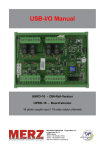
Operations Manual
USB Industry Control Board
Operations Manual
USB Industry Control Board
SMARTLAB
USB INDUSTRY CONTROL BOARD
CHAPTERS
OPERATION MANUAL
1. Introduction…………………………………..……
2. Hardware Configuration…………………..……....
3. Diagnostic under Windows/XP ………………..…
4. Software Programming under Windows/XP and
Linux……………………………………………..……
1
4
14
15
APPENDICES
A. Warranty Information…………………………….. 16
Decision Group Inc.
DECISION Group Inc.
- i -
i
ii DECISION Group Inc.
- ii -
Operations Manual
USB Industry Control Board
Operations Manual
CHAPTER 1
INTRODUCTION
•
The USB industry control board provides 8 ports digital
input/output channels, each port contains 8 digital input/output
channels, which allows to connect 8 channel relay output/photo
isolator input board, 8 channel SSR relay output/photo isolator
input board, 16 channel relay output board, 16 channel photo
isolator input board, and industrial DIN rail mountable terminal
block adapter.
The USB industry control board provides Plug and Play (PnP)
features, it is a programmable I/O interface card for PC/486,
Pentium, or compatibles. The on board high speed 8051 uC
provides USB functions run at 12Mbps full speed or 1.5Mbps
low speed.
The USB industry control board can be connected to computer
by using USB or RS232, RS422/RS485 communication links.
The features of USB industry control board are:
•
•
•
•
•
•
•
•
•
•
•
USB Industry Control Board
channel relay output board, 16 channel photo isolator
input board, and industrial DIN rail mountable terminal
block adapter.
Allow to connect RS232 or RS422/RS485 extension
board with DB9 connector.
Power supplied from external DC +12V/1.5A.
Each digital I/O voltage range from 0V to 3.5V.
0 to 0.4V inactive
2.8 to 3.4V active
Suitable for Linux, MS/WINDOWS, ... etc.
Operating temperature range from 0 to 33C.
Relative humidity rage from 0 to 90%.
PACKAGE CONTENTS:
• USB industry control board.
• USB cable.
• Optional extension board with DB9 connector, select
one of the following:
1. RS232 KIT DCI09031800_A
2. RS422/485 KIT DCI09031800_B
• User’s manual.
• Decision Studio CD for USB LAB KITS software.
• Warranty form.
USB 2.0with Plug and Play (PnP) features.
High speed 8051 uC core.
Support USB ID selection to identify USB device.
Support 8 ports 8 digital input/output channels, total 64
digital input/output channels.
Support extra 8 digital input/output channels, which are
direct driven by 8051 chip.
Allows to connect DECISION industry products: 8
channel relay output/photo isolator input board, 8
channel SSR relay output/photo isolator input board, 16
DECISION Group Inc.
- 1 -
1
2
DECISION Group Inc.
- 2 -
Operations Manual
USB Industry Control Board
Operations Manual
USB Industry Control Board
CHAPTER 2
HARDWARE CONFIGURATION
Before you use the USB industry control board, please ensure
that the jumpers and switches setting. The proper jumper and
switches settings for the USB industry control board are
described in the following.
2.1 Switch Settings
1. S1 Reset
The S1 switch is used to reset 8051, the signal assignments are
shown in the following.
Pin
3,4
1,2
Signals
Reset SW+
Reset SW-
2. S2 USB ID
The S2 switch is used to identify USB card ID. Please set
different card ID to each card (do not duplicate card ID setting).
DECISION Group Inc.
- 3 -
3
4
DECISION Group Inc.
- 4 -
Operations Manual
USB Industry Control Board
Operations Manual
USB Industry Control Board
2.2 Jumper Settings
1
ON
OFF
ON
OFF
ON
OFF
ON
OFF
ON
OFF
ON
OFF
ON
OFF
ON
OFF
2
ON
ON
OFF
OFF
ON
ON
OFF
OFF
ON
ON
OFF
OFF
ON
ON
OFF
OFF
3
ON
ON
ON
ON
OFF
OFF
OFF
OFF
ON
ON
ON
ON
OFF
OFF
OFF
OFF
4
ON
ON
ON
ON
ON
ON
ON
ON
OFF
OFF
OFF
OFF
OFF
OFF
OFF
OFF
Card ID
-14
13
12
11
10
9
8
7
6
5
4
3
2
1
0
1. External Power Input (J1)
SGND
+12V
. .
The power of USB industry control board can be supplied from
USB, however, if USB can not supply enough power, the
external power is need. To input external power, please use the
pin 1 and pin 2 connectors of J1. Be careful to input DC +12V
power.
2.3 USB Connector
1. USB Connector
3. Down load revised firmware
When the S2 switch is set to ON ON ON ON status, means
down load revised firmware. please follow the steps shown in
the following:
1. Set S2 to ON ON ON ON.
2. Run USBBootloader program to down load revised firmware.
The USB connector is connected to computer USB port by
using USB cable.
2.4 Connector and Jumper for Serial Communication
1. The connctor of serial communication(J2)
To use RS422/RS485/RS232, please connect J2 to extension
board by 10 pins flat cable.
DECISION Group Inc.
- 5 -
5
6
DECISION Group Inc.
- 6 -
Operations Manual
USB Industry Control Board
2. Enable Serial Port (J3)
1
Operations Manual
USB Industry Control Board
2
. .
J3 is used enable serial port communication, when short the J3,
means enable serial port, otherwise, when open the J3, the
serial port communication is disable.
2.5 Extension Board for Serial Communication
Extension boards with DB9 connector for RS232 or
RS422/RS485 are optional products, user can connect USB
industry control board to computer by using serial
communiction. Please follow the steps in belows:
1. By using 10 pins flat cable to connect J2 of USB industry
control board and CP1(RS232)/CP2(RS422/RS485) on the
extension board.
2. Connect J1(RS232)/J2(TS422/RS485) of extension board
to computer RS232 or RS422/RS485 port.
The diagram of these extension boards are shown in the
following:
DECISION Group Inc.
- 7 -
7
8
DECISION Group Inc.
- 8 -
Operations Manual
USB Industry Control Board
1. RS422/RS485 Selection (MS1)
1 2 3
. . .
The MS1 is located at RS422/RS485 extension board. MS1 is
used to set RS422/RS485 communication, when short pin 1 and
pin 2, means set RS422. When short pin 2 and pin 3, means set
RS485.
2. Long Distance Communication (MS2)
Operations Manual
JP1
Pin
1
2
3
4
5
6
7
8
9
10
Signal
DIO0
DIO1
DIO2
DIO3
DIO4
DIO5
DIO6
DIO7
SGND
SGND
USB Industry Control Board
Description
Port DIO/Line 0
Port DIO/Line 1
Port DIO/Line 2
Port DIO/Line 3
Port DIO/Line 4
Port DIO/Line 5
Port DIO/Line 6
Port DIO/Line 7
Signal Ground
Signal Ground
The MS2 is located at RS422/RS485 extension board. MS2 is
used to set long distance communication, when short the MS2,
means long distance communication. Ohterwise, open the MS2,
means normal distance communication.
2.6 Connector Assignments
The input/output signals of USB industry control board are
assigned in the JP2 to JP5 connector and an extra DIO port JP1
connector, its pin assignments are show in the below.
DECISION Group Inc.
- 9 -
9
10 DECISION Group Inc.
- 10 -
Operations Manual
JP2
Pin
1
2
3
4
5
6
7
8
9
10
11
12
13
14
15
16
17
18
19
20
21
22
23
24
25
26
Signal
+12V
SGND
+12V
SGND
P0D00
P0D01
P0D02
P0D03
P0D04
P0D05
P0D06
P0D07
P1D00
P1D01
P1D02
P1D03
P1D04
P1D05
P1D06
P1D07
SGND
SGND
+5V
SGND
-12V
SGND
USB Industry Control Board
JP3
Pin
1
2
3
4
5
6
7
8
9
10
11
12
13
14
15
16
17
18
19
20
21
22
23
24
25
26
Description
Internal DC +12V Power
Signal Ground
nternal DC +12V Power
Signal Ground
Port 0/Line 0
Port 0/Line 1
Port 0/Line 2
Port 0/Line 3
Port 0/Line 4
Port 0/Line 5
Port 0/Line 6
Port 0/Line 7
Port 1/Line 0
Port 1/Line 1
Port 1/Line 2
Port 1/Line 3
Port 1/Line 4
Port 1/Line 5
Port 1/Line 6
Port 1/Line 7
Signal Ground
Signal Ground
+5V Power
Signal Ground
Internal DC -12V Power
Signal Ground
DECISION Group Inc.
- 11 -
Operations Manual
11
Signal
+12V
SGND
+12V
SGND
P2D00
P2D01
P2D02
P2D03
P2D04
P2D05
P2D06
P2D07
P3D00
P3D01
P3D02
P3D03
P3D04
P3D05
P3D06
P3D07
SGND
SGND
+5V
SGND
-12V
SGND
USB Industry Control Board
Description
Internal DC +12V Power
Signal Ground
nternal DC +12V Power
Signal Ground
Port 2/Line 0
Port 2/Line 1
Port 2/Line 2
Port 2/Line 3
Port 2/Line 4
Port 2/Line 5
Port 2/Line 6
Port 2/Line 7
Port 3/Line 0
Port 3/Line 1
Port 3/Line 2
Port 3/Line 3
Port 3/Line 4
Port 3/Line 5
Port 3/Line 6
Port 3/Line 7
Signal Ground
Signal Ground
+5V Power
Signal Ground
Internal DC -12V Power
Signal Ground
12 DECISION Group Inc.
- 12 -
Operations Manual
JP4
Pin
1
2
3
4
5
6
7
8
9
10
11
12
13
14
15
16
17
18
19
20
21
22
23
24
25
26
Signal
+12V
SGND
+12V
SGND
P4D00
P4D01
P4D02
P4D03
P4D04
P4D05
P4D06
P4D07
P5D00
P5D01
P5D02
P5D03
P5D04
P5D05
P5D06
P5D07
SGND
SGND
+5V
SGND
-12V
SGND
USB Industry Control Board
JP5
Pin
1
2
3
4
5
6
7
8
9
10
11
12
13
14
15
16
17
18
19
20
21
22
23
24
25
26
Description
Internal DC +12V Power
Signal Ground
nternal DC +12V Power
Signal Ground
Port 4/Line 0
Port 4/Line 1
Port 4/Line 2
Port 4/Line 3
Port 4/Line 4
Port 4/Line 5
Port 4/Line 6
Port 4/Line 7
Port 5/Line 0
Port 5/Line 1
Port 5/Line 2
Port 5/Line 3
Port 5/Line 4
Port 5/Line 5
Port 5/Line 6
Port 5/Line 7
Signal Ground
Signal Ground
+5V Power
Signal Ground
Internal DC -12V Power
Signal Ground
DECISION Group Inc.
- 13 -
Operations Manual
13
Signal
+12V
SGND
+12V
SGND
P6D00
P6D01
P6D02
P6D03
P6D04
P6D05
P6D06
P6D07
P7D00
P7D01
P7D02
P7D03
P7D04
P7D05
P7D06
P7D07
SGND
SGND
+5V
SGND
-12V
SGND
USB Industry Control Board
Description
Internal DC +12V Power
Signal Ground
nternal DC +12V Power
Signal Ground
Port 6/Line 0
Port 6/Line 1
Port 6/Line 2
Port 6/Line 3
Port 6/Line 4
Port 6/Line 5
Port 6/Line 6
Port 6/Line 7
Port 7/Line 0
Port 7/Line 1
Port 7/Line 2
Port 7/Line 3
Port 7/Line 4
Port 7/Line 5
Port 7/Line 6
Port 7/Line 7
Signal Ground
Signal Ground
+5V Power
Signal Ground
Internal DC -12V Power
Signal Ground
14 DECISION Group Inc.
- 14 -
Operations Manual
USB Industry Control Board
CHAPTER 3
The USB industry control board can be install to Windows/XP
via USB plug and play function, please follow the steps shown
in the following:.
1. For optimum PnP functionality, please install one board at a
time.
2. Windows/XP will detect the new USB industry control
board that is installed in your computer, and will prompt
you for a proper driver.
3. Install Virtual COM port (VCP) drivers which is in Drivers
\ Virtual COM \ Vertual_COM.inf.. Virtual COM port
(VCP) drivers cause the USB device to appear as an
additional COM port available to the PC. Application
software can access the USB device in the same way as it
would access a standard COM port.
4. After Windows/XP has detected and configured all ports,
you may begin using the USB industry control board. To
verify that the installation process completed successfully,
please proceed into the Control Panel / System / Device
Manager.
5. Locate the additional COM ports in the ports section, and
Digital I/O and analog to digital device from HID device..
- 15 -
USB Industry Control Board
CHAPTER 4
WINDOWS/XP CONFIGURATION
DECISION Group Inc.
Operations Manual
15
SOFTWARE PROGRAMMING UNDER
WINDOWS/XP AND LINUX
The LABKIT_host is a diagnostic program to test your USB
industry control board under Windows/XP.User can get
LABKIT_host programs from Decision Studio CD.
The USB industry control board can be installed in the Linux
by using serial device driver supported by Linux. For more
details, please refer to 'setserial' man-pages. After the Linux
recognizes the serial port, it will assign device name as
/dev/ttyACM0 for the first serial port, and /dev/ttyACM1 for
the second serial port, …etc.
To input/output data from USB industry control board, please
use Hid API functions. User can get Hid API functions from
Decision Studio package.
16 DECISION Group Inc.
- 16 -
Operations Manual
USB Industry Control Board
Operations Manual
USB Industry Control Board
materials and workmanship and be fully functional under
normal usage.
APPENDIX A
WARRANTY INFORMATION
A.1 Copyright
Copyright DECISION COMPUTER INTERNATIONAL CO.,
LTD. All rights reserved. No part of SmartLab software and
manual may be produced, transmitted, transcribed, or translated
into any language or computer language, in any form or by any
means, electronic, mechanical, magnetic, optical, chemical,
manual, or otherwise, without the prior written permission of
DECISION COMPUTER INTERNATIONAL CO., LTD.
Each piece of SmartLab package permits user to use SmartLab
only on a single computer, a registered user may use he
program on a different computer, but may not use the program
on more than one computer at the same time.
Corporate licensing agreements allow duplication and
distribution of specific number of copies within the licensed
institution. Duplication of multiple copies is not allowed
except through execution of a licensing agreement. Welcome
call for details.
In the event of the failure of a SmartLab product within
the specified warranty period, SmartLab will, at its option,
replace or repair the item at no additional charge. This
limited warranty does not cover damage resulting from
incorrect use, electrical interference, accident, or modification
of the product.
All goods returned for warranty repair must have the serial
number intact. Goods without serial numbers attached will not
be covered by the warranty.
The purchaser must pay transportation costs for goods returned.
Repaired goods will be dispatched at the expense of SmartLab.
To ensure that your SmartLab product is covered by the
warranty provisions, it is necessary that you return the
Warranty card.
Under this Limited Warranty, SmartLab's obligations will be
limited to repair or replacement only, of goods found to be
defective a specified above during the warranty period.
SmartLab is not liable to the purchaser for any damages or
losses of any kind, through the use of, or inability to use, the
SmartLab product.
A.2 Warranty Information
SmartLab warrants that for a period of one year from the date
of purchase (unless otherwise specified in the warranty card)
that the goods supplied will perform according to the
specifications defined in the user manual. Furthermore that
the SmartLab product will be supplied free from defects in
DECISION Group Inc.
- 17 -
17
SmartLab reserves the right to determine what constitutes
warranty repair or replacement.
Return Authorization: It is necessary that any returned goods
are clearly marked with an RA number that has been issued by
18 DECISION Group Inc.
- 18 -
Operations Manual
USB Industry Control Board
SmartLab. Goods returned without this authorization will not
be attended to.
DECISION Group Inc.
- 19 -
19