1
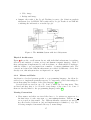
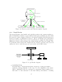
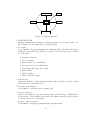
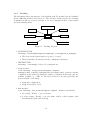
The University of Reading
Department of Computer Science
Technical Report number RUCS/2002/TR/11/001/A
Reading People Tracker
Version 1.12
Reference Manual
Tugdual Le Bouffant1
Nils T Siebel1
Stephen Cook2
Steve Maybank1
1
2
Computational Vision Group
Applied Software Engineering Research Group
Department of Computer Science
The University of Reading
November 2002
1
Funding provided by the European Union, grant ADVISOR (IST-1999-11287).
2
Funding provided by the EPSRC, grant DESEL (GR/N01859).
Tugdual Le Bouffant1 , Nils T Siebel1,∗,† , Stephen Cook2 , Steve Maybank1
Reading People Tracker version 1.12
Reference Manual
Abstract
The Reading People Tracker has been maintained at the Department’s
Computational Vision Group for the past 3 years. During this time,
it has undergone major changes. The software has been completely
restructured, adapted for multiple cameras and multiple trackers per
camera, and integrated into the automated surveillance system ADVISOR.
Part of this process has been the creation of extensive documentation
from the source code, of which this manual is the most important part.
The manual is mostly written for programmers and covers a range of
issues, from architectural descriptions up to detailed documentation on
the software process now to be followed for all maintenance work on the
tracker.
Keywords. Software Process Documentation, Design Patterns, Software Architecture, Reference Manual, People Tracking.
1
Computational Vision Group, 2 Applied Software Engineering Research Group
Department of Computer Science, The University of Reading
∗
Correspondence to: Nils T Siebel, Computational Vision Group, Department of
Computer Science, The University of Reading, PO Box 225, Whiteknights, Reading
RG6 6AY, United Kingdom.
†
E-Mail: [email protected]
2
Contents
Contents
4
1 Introduction
1.1 History . . . . . . . . . . . . . . . . . . . . . . . . . . . . . . . . . . .
1.2 The Need to Redesign the Code . . . . . . . . . . . . . . . . . . . . .
1.3 Contributions . . . . . . . . . . . . . . . . . . . . . . . . . . . . . . .
6
6
6
8
2 System Architecture: Overview
2.1 Static Organisation . . . . . . . . . . .
2.1.1 Domain Model . . . . . . . . .
2.1.2 Class Diagram . . . . . . . . . .
2.2 Dynamic Organisation . . . . . . . . .
2.2.1 Use Case Figure 2: Standalone
2.2.2 Use Case Figure 3: ADVISOR .
2.2.3 Robustness Diagram . . . . . .
2.2.4 Sequence Diagram . . . . . . .
.
.
.
.
.
.
.
.
.
.
.
.
.
.
.
.
.
.
.
.
.
.
.
.
.
.
.
.
.
.
.
.
.
.
.
.
.
.
.
.
.
.
.
.
.
.
.
.
.
.
.
.
.
.
.
.
.
.
.
.
.
.
.
.
.
.
.
.
.
.
.
.
.
.
.
.
.
.
.
.
.
.
.
.
.
.
.
.
.
.
.
.
.
.
.
.
.
.
.
.
.
.
.
.
.
.
.
.
.
.
.
.
.
.
.
.
.
.
.
.
.
.
.
.
.
.
.
.
.
.
.
.
.
.
.
.
9
9
9
10
10
10
12
14
15
3 Design Patterns
3.1 Requirements for the People Tracker
3.2 The way to use Classes . . . . . . . .
3.2.1 Architectural Pattern . . . . .
3.2.2 Idioms and Rules . . . . . . .
3.3 Patterns Implementation . . . . . . .
3.3.1 Inputs . . . . . . . . . . . . .
3.3.2 ReadingPeopleTracker . . . .
3.3.3 PeopleTracker . . . . . . . . .
3.3.4 Camera . . . . . . . . . . . .
3.3.5 Tracking . . . . . . . . . . . .
3.3.6 Results . . . . . . . . . . . . .
.
.
.
.
.
.
.
.
.
.
.
.
.
.
.
.
.
.
.
.
.
.
.
.
.
.
.
.
.
.
.
.
.
.
.
.
.
.
.
.
.
.
.
.
.
.
.
.
.
.
.
.
.
.
.
.
.
.
.
.
.
.
.
.
.
.
.
.
.
.
.
.
.
.
.
.
.
.
.
.
.
.
.
.
.
.
.
.
.
.
.
.
.
.
.
.
.
.
.
.
.
.
.
.
.
.
.
.
.
.
.
.
.
.
.
.
.
.
.
.
.
.
.
.
.
.
.
.
.
.
.
.
.
.
.
.
.
.
.
.
.
.
.
.
.
.
.
.
.
.
.
.
.
.
.
.
.
.
.
.
.
.
.
.
.
.
.
.
.
.
.
.
.
.
.
.
.
.
.
.
.
.
.
.
.
.
.
15
15
16
16
17
22
22
24
25
26
28
29
.
.
.
.
.
.
.
.
.
30
30
31
31
31
32
32
33
33
33
.
.
.
.
.
.
.
.
.
.
.
4 How to Create or Design and Implement...
4.1 A New Shape Model . . . . . . . . . . . . .
4.2 A New ImageSource . . . . . . . . . . . . .
4.3 A New Tracker or Detector Module . . . . .
4.3.1 Inputs and Results . . . . . . . . . .
4.3.2 Frame Processing . . . . . . . . . . .
4.3.3 Detection . . . . . . . . . . . . . . .
4.3.4 Tracking . . . . . . . . . . . . . . . .
4.3.5 Base Tracker . . . . . . . . . . . . .
4.4 Actual Configuration And Algorithm Of The
. . . . . . . . .
. . . . . . . . .
. . . . . . . . .
. . . . . . . . .
. . . . . . . . .
. . . . . . . . .
. . . . . . . . .
. . . . . . . . .
Tracking Task
.
.
.
.
.
.
.
.
.
.
.
.
.
.
.
.
.
.
.
.
.
.
.
.
.
.
.
.
.
.
.
.
.
.
.
.
5 Configuration Files Organisation
34
6 Libraries Description
35
4
7 Reverse engineering of the RPT code using Rational Rose’s C++
Analyser Module
40
7.1 Rational Rose C++ Analyser . . . . . . . . . . . . . . . . . . . . . . . 40
7.2 Error Messages . . . . . . . . . . . . . . . . . . . . . . . . . . . . . . 43
References
46
5
1
Introduction
This document gives an overview of the Reading People Tracker in the Computational Vision Group, Department of Computer Science, at the University of Reading.
The aim of this documentation is to provide information in order to help future development of the People Tracker. Most of the material presented in this section and
section 2 was taken from [1].
1.1
History
The original People Tracker was written by Adam Baumberg at the University of
Leeds in 1993–1995 using C++ running under IRIX on an sgicomputer. It was a
research and development system within the VIEWS project and a proof of concept
for a PhD thesis [2]. The main focus during development was on functionality and
experimental features which represented the state-of-the-art in people tracking at
that time. Only a few software design techniques were deployed during the initial
code development. The only documentation generated was a short manual on how
to write a program using the People Tracking module.
In 1995–1998 the People Tracker was used in a collaboration between the Universities of Leeds and Reading in the IMV project. The software was changed at
the University of Reading to inter-operate with a vehicle tracker which ran on a
Sun/Solaris platform [3]. Only little functionality was changed and added during
this time and no new documentation was created.
Starting in 2000, the People Tracker has been changed for its use within the
ADVISOR system shown in Figure 8. This new application required a number of
major changes on different levels.
1.2
The Need to Redesign the Code
The planned use of the People Tracker within the ADVISOR System carried many
requirements that could not be met by the original implementation. Most of the
new requirements arose from the fact that the People Tracker would now have to be
part of an integrated system, while earlier it was standalone. The use of the People
Tracker within the ADVISOR system also meant moving it “from the lab to the real
world” which necessitated many changes. Figure 8 shows how the People Tracking
module is connected to the other components of the ADVISOR system.
The new requirements for the People Tracker were:
• The People Tracker has to be fully integrated within the ADVISOR system.
• It has to run multiple trackers, for video input from multiple cameras (original
software: one tracker, one camera input).
• The ADVISOR system requires the People Tracker to operate in realtime. Previously, the People Tracker read video images from hard disk which meant there
were no realtime requirements.
6
• Within ADVISOR, the People Tracker has to run autonomously once it has been
set up, without requiring input from an operator and without the possibility
to write any message to screen or display any image.
• The software has to be ported from sgi to a standard PC running GNU/Linux
to make economical system integration feasible.
The status of the existing People Tracker was evaluated in relation to the new requirements. It was observed that the system had significant deficiencies which hindered
the implementation of the required new functionality:
• The heavy use of global variables and functions meant that multiple cameras
could not be used.
• Except a few pages of operating manual, no other documentation was available. As a result, changing the software to add functionality, etc. required
disproportionate amount of effort.
• There were very little comments in the source code which made it difficult to
read and understand.
• The names of some of the classes and methods were misleading.
In the years 2000 and 2001, the People Tracker was reverse-engineered and reengineered. The aim of the reverse engineering/re-engineering step was:
• to understand the program and the design,
• to find and correct design flaws and
• to recover all the software engineering artefacts like the requirements and the
design documents.
From the source code, the class diagram was obtained by using the tool Rational Rose
2000e [4]. The analysis of the class diagram revealed that many class names did not
reflect the inheritance hierarchy, a number of classes were found to be redundant,
and many classes had duplicated functionality. The following correctional steps were
performed:
• Redundant classes were removed.
• Global variables and functions were eliminated and their functionality distributed into both existing and new classes. Exceptions were global helper
functions like min(), max() etc which were extracted and moved into one C++
module.
• Many refactoring techniques [5] were applied, such as:
7
– Filtering out functionality duplicated in similar classes and moving it into
newly created base classes.
– Re-distribution of functionality between classes and logical modules.
– Re-distribution of functionality between methods.
• Consistent renaming of file names to reflect classes defined in them.
• Meaningful names were given to classes and methods.
• The previous version of the code contained many class implementations in the
header files; they were moved to the implementation (.cc) files.
• Assertions[6, chap. 6] were introduced at strategic points in the existing code
and in all of the new code.
• From both static analysis and dynamic analysis [7], a requirement document
and the UML artefacts like the Use Case, component, and package level sequence diagrams [8] were obtained. The UML diagrams have been shown in
Figures 3 through 7 respectively.
In the final step, the remaining part of the required new functionality was incorporated into the re-engineered People Tracker. This includes the addition of separate
processing threads for each video input, addressing the synchronisation and timing requirements etc. A newly created master scheduler manages all processing,
in order to guarantee realtime performance with multiple video inputs. This version of the People Tracker incorporates most of the functionality needed for its use
within ADVISOR and improvements to the people tracking algorithms which make
it appropriate for the application [9]. The module has been validated against test
data. Currently, the final stage of system integration is being undertaken, and this
document, together with a User Manual to be written, completes the documentation.
1.3
Contributions
The following people have contributed to the Reading People Tracker up to the
current version 1.12 of the software (dated Mar 11 2002).
1. Design / Coding
• Adam Baumberg (AMB), The University of Leeds.
• Nils T Siebel (NTS), The University of Reading.
• Tony Heap (AJH), The University of Leeds.
• Tom Grove (TDG), The University of Reading.
2. Coding
• Daniel Ponsa Mussarra (DPM), Universidad Autónoma de Barcelona.
8
• Philip Elliott (PTE), The University of Reading.
• Rémi Belin (RB), Université de Toulon et du Var.
• Tugdual Le Bouffant (TLB), The University of Reading.
3. Documentation
• Tugdual Le Bouffant (TLB), The University of Reading
• Nils T Siebel (NTS), The University of Reading
• Daniel Rodrı́guez Garcı́a (DRG), The University of Reading
• Stephen Cook, The University of Reading
2
System Architecture: Overview
2.1
Static Organisation
The static organisation describes the organisation of the different parts of the code
such as libraries and the links between them. This organisation is important to
understand the code architecture and the use of each library in the program.
2.1.1
Domain Model
The domain model, shown in Figure 1, is the representation of the libraries used
and developed for the Reading People Tracker program. The yellow blocks represent
the parts which are libraries of our own source code. The other parts are standard
libraries and include files. This diagram shows the relationship between each library,
the arrows means that the library pointed is used by the the one which point: PCA
library will use some function from the the matrix library.
• PCA: Principal Component Analysis and shape modelling, used by the Active
Shape Tracker. PCA is used to generate the space of pedestrian outlines from
training examples.
• matrix: library of tools for matrix calculations.
• data: set of standard data features (skeleton, profiles, human features, etc).
• utils: this library is the variable configuration manager.
• tracking: this library contains all the tracker, detector and camera classes.
• imgsrc: this library deals with images format and sources.
• xml: this library deals with XML files.
9
Figure 1: Software Packages of the People Tracker
2.1.2
2.2
Class Diagram
Dynamic Organisation
This section describes the dynamic organisation of the Reading People Tracker in 3
subsections:
• Use Case Model: deals with the actions performed by the system under the
actors’ interactions. Who are the users of the system (the actors), and what
are they trying to do?
• Robustness Diagram: defines the types of object from the use case model.
What object are needed for each use case?
• Sequence Diagram: represents the object flow. How do the objects collaborate
within each use case?
2.2.1
Use Case Figure 2: Standalone
Use Case Diagram
This use case shows the action sequence that actors:
• Video Database and
10
• Developer,
perform with the system in Standalone mode to achieve a particular goal which is
the result of the Track New People Position use case.
Figure 2: Use Cases for the People Tracker (in Standalone/Development Mode)
High Level Use Case
Use Case: Decompress JPEG Image.
Actor: Video Database, Internal Motion Detection, Track New People Position.
Description: JPEG images are decompressed form the database of images which
will be used by the Motion Detection module and the Track New People Position
module. This will be replicated per each video sequence from each cameras.
Use Case: Internal Motion Detector.
Actor: JPEG image decompressed, Track New People Position.
Description: The motion detection is done using the difference of the image with
people moving and the background image, this will be used by the Track New People Position module to track the motion detected. This will be replicated per camera.
Use Case: Determine Tracking Parameters.
Actor: Developer, Track New People Position.
Description: The developer enters some variable configuration needed by the system
to run, this will configure the variables for the Track New People Position module.
This is replicated per cameras and per tracker used.
Use Case: Predict Old People Position.
Actor: Track New People Position.
Description: On each frame processing a prediction is done on the next position of
a person tracked, this prediction is then checked and validate if correct. This will
be replicate per camera.
11
Use Case: Track New People Position.
Actors: Decompress JPEG Image, Internal Motion Detector, Predict Old Object
Position, Determine Tracking Parameters and Generate Tracking Result.
Description: This the Central task of the system, it generates the result of the
tracking of a new person’s position. Non replicated.
Use Case: Fuse Data from Cameras.
Actor: Generate Tracking Result.
Description: This use case shows that all the result of each cameras are fused and
sent to the Generate Tracking Results module. Non replicated.
Use Case: Generate Tracking output.
Actors: Track New People Position, Output Tracking Results to Screen and Fuse
Data from Cameras.
Description: Generates the Tracking result form all the cameras. Non replicated.
Use Case: Output Tracking Result to Screen.
Actor: Generate Tracking Result, Developer.
Description: This use case will use the result generated by the tacking to display
the result on screen to the Developer. Non replicated.
2.2.2
Use Case Figure 3: ADVISOR
Use Case Diagram
this use case is a sequence of actions that the following actors perform with the
People Tracking subsystem of ADVISOR:
• the Video Capture Module (from Thales),
• the External Motion Detection Module (from INRIA) and
• the Behaviour Analysis Module (to INRIA),
The goal is to Track New People Position with Video and Motion Detection as inputs
and the result as output sent to the Behaviour Analysis.
12
Figure 3: Use Cases for the People Tracker (as a Subsystem of ADVISOR)
High Level Use Case
Use Case: Decode Motion Detection Data
Actor: External Motion Detection Module, Track New People Position.
Description: Decode the XML data into data usable in the PeopleTracker program.
Replicated per camera.
Use Case: Predict Old People Position.
Actor: Track New People Position.
Description: On each frame processing a prediction is done on the next position of
a people tracked, this prediction is then checked and validate if correct. This will be
replicate per camera.
Use Case: Track New People Position.
Actors: Video Capture Module, Predict Old People Position and Decode Motion
Detection Data.
Description: This the Central task of the system, it generates the result of the
tracking of a new people position. This will be replicated per camera.
Use Case: Fuse Data from Cameras.
Actor: Generate Tracking Results.
Description: This use case shows that all the result of each cameras are fused and
sent to the Generate Tracking Result module. Non replicated.
Use Case: Generate Tracking output.
Actors: Track New People Position, Encode Tracking Results into XML and Fuse
Data from Cameras outputs.
Description: This use case generate the Tracking result form all the cameras.
Replicated per camera.
Use Case: Encode Tracking Result into XML
13
Actor: Behaviour Analysis Module, Generate Tracking Results
Description: Result generated are encode into XML format to be transported via
Ethernet to an other module which will use these result to perform the behaviour
analysis.
2.2.3
Robustness Diagram
The Robustness Analysis involves analysing each of the use cases and identifying a
set of objects that will participate in the use case, then classifying those into three
types of objects:
• Boundary object, which actors use in communicating with the system.
• Entity object, which represent a result and which will be used for external
tasks.
• Control objects, which is the action performed by the system.
Figure 4: Standalone Robustness Diagram
Figure 5: ADVISOR Robustness Diagram
14
2.2.4
Sequence Diagram
This diagram is also named interaction diagram. It shows the flow of requests between objects. Interaction modelling is the phase in which the threads that weave
objects together are built. At this stage it is possible to see how the system performs
useful behaviour. The sequence diagrams for the People Tracker have been shown in
Figures 6 and 7.
Figure 6: Standalone Sequence Diagram (at a Higher Level)
3
Design Patterns
Design patterns systematically describe names, motivate, and explain a general design that addresses a recurring design problem in all object-oriented systems. They
describe the problem, the solution, when to apply the solution, and its consequences.
They also give implementation hints and examples. The solution is a general arrangement of objects and classes that solve the problem in a particular context.
3.1
Requirements for the People Tracker
The People Tracker has to support two modes of operation:
• Standalone mode see figure 2 section 2.2.1,
• Subsystem of ADVISOR see figure 3 section 2.2.2.
15
Figure 7: ADVISOR Sequence Diagram (at a Higher Level)
This two mode of operation are controlled at compile time using preprocessor
#defines. The ADVISOR mode is enabled if and only if THALES_WRAPPER is defined.
Image output is disabled if NO_DISPLAY is defined, and it has to be define in ADVISOR
mode.
3.2
The way to use Classes
Design patterns are divided in 2 categories: Architectural pattern, Idioms and Rules.
3.2.1
Architectural Pattern
An architectural pattern expresses a fundamental structural organisation schema for
software systems. It provides a set of predefined subsystems, specifies their responsibilities, and includes rules and guidelines for organising the relationships between
them [10, p. 12].
Conceptual / Logical Architecture
People Tracking is one the six subsystem of ADVISOR. The Reading People Tracker
module has to communicate with two others, receiving information and generate the
result to be sent to an other module.
• Input: The video capture and motion detection subsystems are done by respectively Thales and INRIA. These subsystems send to the People Tracker XML
files containing the images:
1. Motion image (foreground with blob)
16
2. Video image
3. Background image
• Output: the result of the People Tracking is sent to the behaviour analysis
subsystem done by INRIA. The result sent by People Tracker is an XML file
containing the information on tracked people.
Figure 8: The ADVISOR System with its 6 Subsystems
Physical Architecture
Figure 8 shows the overall system layout, with individual subsystems for tracking,
detection and analysis of events, storage and human-computer interface. Each of
these subsystems is implemented to run in realtime on off-the-shelf PC hardware,
with the ability to process input from a number of cameras simultaneously. The
connections between the different subsystems are realised by Ethernet. As we have
already seen, this subsystem has one input and one output.
3.2.2
Idioms and Rules
An idiom is a low-level pattern specific to a programming language. An idiom describes how to implement particular aspects of components or the relationships between them using the features of the given language [10, p 14].
Several idioms are used in our code. Some of which are very important. They
are listed and they have to be followed for any change of the source code. Some of
them are directly linked to the programming language rules [11].
Naming Conventions
• Class names and their associated files have to be written as uppercase for
the first letter of each component, e.g. ActiveShapeTracker. Underscores ’ ’
are not used in class names. Two different filename extensions are used for
C++ files header declaration (.h) and implementation definition (.cc). The
following examples demonstrate the way to name things:
17
– ClassName
– associated files ClassName.h for the class declaration and ClassName.cc
for its implementation.
– method_name() (within a class)
– a_local_variable (global variables are forbidden)
– get_a_variable(), “Accessor”
– set_a_variable(), “Modifier”
• All comments are to be written in plain British English.
• Use the C++-style // for comments, not the C-style /* */.
• Standard use of 8 character tabulation.
• All main() programs and test cases have to be situated in the progs/ subdirectory.
Include Files
• Use the directive #include "filename.h" for user-prepared include files
(i.e. those which are part of our own code).
• Use the directive #include <filename.h> for include files from system libraries.
• Every include file must contain a mechanism that prevents multiple inclusions
of the file. The defined “guard definition” has to be written in uppercase
letters, it has to begin and finish with 2 underscores, and each term has to
be separated by one underscore. For example, at beginning of the include file
called |ActiveShapeTracker.h— you will see
#ifndef __ACTIVE_SHAPE_TRACKER_H__
#define __ACTIVE_SHAPE_TRACKER_H__
This exact format has to be adopted.
Functions and Variables
• Global variables and functions must be avoided; they almost always violate the
principle of encapsulation. Instead use static member functions of classes, e.g.
there is a PeopleTracker::create_new_id() static member function to create
a new, globally unique id from any thread.
18
• Minimal use of #define macros, use inline functions instead. The normal reason for declaring a function inline is to improve performance. Small functions,
such as access functions, which return the value of a member of the class and
so-called forwarding functions which invoke another function should normally
be inline.
• The difference between int &a (or int *a) and int& a is that the first one
seems to associate the & or (or *, for that matter) with the type, and the second
one with the variable. From the compiler point of view there is no difference
between them. Associating the & or * with the type name reflects the desire
of some programmers for C++ to contain a separate pointer type. However,
neither the & nor the * is distributive over a list of variables. See for example
int *a,b; Here b is declared as an integer (not a pointer to an integer), only
a is a pointer to an integer.
For these reasons, never write int& a, only int &a.
• Assertions, using the assert(expression) macro (defined by the ISO C include file <assert.h>), should be used in order to find programming errors
at an early stage. Assertions are generally used to help verify that a program is operating correctly, with expression being devised in such a way that
it evaluates to true only when there is no error in the program. For example, the constructor to the Image class has a parameter for the image width.
assert (the_width > 0); is used to make sure that the given width is valid,
because if it is not, something else has gone wrong in the past. Instead of
trying to continue, the error should be found. This is done with the help of
the mentioned assertion. See [6, chap. 6] for further reading.
• The inline function:
– Access functions are to be inline,
– Forwarding functions are to be inline,
The normal reason for declaring a function inline is to improve the performance of your program. Correct use of inline functions may also lead to
reduced size of code.
• A virtual function is a member function that is declared within a base class
and redefined by a derived class. In essence, virtual function implement the
“one interface, multiple methods” philosophy that underlies polymorphism.
The virtual function within the base class defines the form of the interface to
that function.
• The use of unsigned type: the unsigned type is used to avoid inconsistency an
error generation. It is widely use in the matrix library (e.g., you cannot specify
a negative number of columns for a matrix calculation). Always use unsigned
for variables which cannot reasonably have negative values.
19
• The use of const: this identifier has to be used when you want to keep the value
of a variable. It makes it impossible to overwrite its value. A member function
that does not affect the state of the an object is to be declared const. All
trackers or detectors have to be derived from BaseTracker using pure virtual
methods.
• All types used by more than one class have to be defined in
tracker_defines_type_and_helpers, for instance: the image source type.
Classes
• Definitions of classes that are only accessed via pointers (*) or references (&)
shall not be included as include files. Instead, use forward declarations, for
example, in ActiveShapeTracker.h one can find:
class Image;
class ActiveModel;
...
in ActiveShapeTracker.cc these forward declared classes are defined by including the respective header files:
#include "Image.h"
#include "ActiveModel.h"
...
• Use base classes where useful and possible. A base class is a class from which
no object is created; it is only used as a base class for the derivation of other
classes. For example see BaseTracker class
• public, protected, private sections of a class are to be declared in that
order. By placing the public section first, everything that is of interest to a
user is gathered in the beginning of the class definition. The protected section
may be of interest to designers when considering inheriting from the class. The
private section contains details that should have the least general interest.
– public members of a class are member data and functions which are
everywhere accessible by specifying an instance of the class and the name.
– protected members are variables or functions which are accessible by
specifying the name within member functions of derived classes.
– private members are variables or functions which are only accessible
inside the class.
• A friend function has access to all private and protected members of the
class for which it is a friend.
20
Use and Update the Source Code
The Reading People Tracker source code is shared between several developers. To
access the source code it is necessary to use CVS (Concurrent Version System) which
permits to a group of people to work at the same time on the same code. There is a
Master Repository of the Source code you can use it in three ways:
• CVS checkout source_name: this command creates a source/ directory in
the current one containing a personal version of the source code.
• CVS update source_name: this command gives the updated source code .
• CVS commit source_name: this command applies the changes made in the
code to the Master Repository of the Source code.
These command lines are entered in a shell.
When changes in the source code are committed an explanation of the changes
must be put in the CHANGES file in the source directory.
Example Source Code
This example from the PeopleTracker.cc file shows how the code has to be formatted.
• The Comment first describes the method created and the return or parameter
values.
• The indentation: after if expression with comment, carriage return, opening
bracket, carriage return, the inside of the block, carriage return, closing bracket,
carriage return, else...
• Do not use i or j; all variables have a meaning, like the variable
number_of_active_cameras. We are not afraid of the variable name’s length.
• Any implementation which is more than a very few lines of code has to be
written in the .cc file, not in the .h file.
///////////////////////////////////////////////////////////////////////////////
//
//
// int PeopleTracker::get_state() check whether there is an error
//
//
//
// returns the number of active cameras (>= 0) if no error can be detected //
//
< 0 (value of state variable, qv) if there is a known error
//
//
//
///////////////////////////////////////////////////////////////////////////////
int PeopleTracker::get_state()
{
if (state == 0)
// everything OK?
{
21
// count number of active cameras (ie. existing and enabled ‘Camera’s)
unsigned int number_of_active_cameras = 0;
unsigned int index;
for (index = 0; index < number_of_cameras; index++)
if ((cameras[index] != NULL) && (cameras[index]->camera_enabled))
number_of_active_cameras++;
return number_of_active_cameras;
}
else
{
assert (state < 0); // (state != 0) means error and this should be < 0
return state;
// this will hold an error value < 0
}
}
3.3
Patterns Implementation
In this subsection we are dealing with the patterns and their implementation in
the Reading People Tracker. The system patterns are extracted from the Dynamic
Organisation 2.2 and the main classes described are those from the tracking library.
The patterns extracted are:
• The way the Inputs are treated: the Inputs class,
• The Tracking task: the ReadingPeopleTracker main class and the
PeopleTracker, Camera, Tracking classes,
• The Results produced: the Results class.
We can easily understand that the most important part here is the tracking pattern,
for this reason we will not present details about the fused results and output; they
are:
• in Standalone mode: User Interface,
• in ADVISOR mode: usage of XML standard Library.
3.3.1
Inputs
The Inputs class, shown in Figure 9, sets up video input, external motion input and
camera calibration. This class collect all input to given frame and returns actual and
new frame id.
1. CONSTRUCTOR:
Inputs::Inputs(ConfigurationManager *configuration_manager)
ates new configuration manger, Input configuration.
22
Cre-
Configuration Manager
JPEG Source
Calibration
Inputs
Pnm Source
Buffered Slave Image Source
Figure 9: Inputs diagram
2. DESTRUCTOR:
Inputs::~Inputs() delete old sources.
3. Setup Inputs:
void Inputs::setup_inputs()
• Setup video input,
• Setup input for external motion detector:
– Motion image,
– XML regions,
– Background images.
• Setup camera Calibration.
4. Setup Buffered Slave:
bool Inputs::setup_image_source_input(...) returns whether some valid
input has been set up for the specified filename.
• Check for special filename “slave”. Use buffered slave input but fed from
a file source. In order to do that, we determine and create file source first,
to get the image dimensions. Then we open the slave source.
• Open input_source which reads images from hard disk. The following
image formats are recognised: JPEG, PPM, PGM (PNM formats may be
‘compress’ed or ‘gzip’ed).
• Create slave source if we need it. Open slave source to be fed from
\input_source. This feed contains the image dimensions necessary to
instantiate the BufferedSlaveImageSource class.
5. Setup Buffer and XML Files:
bool Inputs::setup_xml_region_source_input(...) Set up buffered slave
and file input XML region source as specified by the filename returns whether
some valid input has been set up.
23
• Check for special filename “slave”. Use buffered slave input which is fed
with input by Thales’ Wrapper. Get the image dimensions.
• Create a NumberedFileSource which reads XML data from hard disk.
Set up file source for the slave. This is a NumberedFileSource.
6. Proceed Inputs:
frame_id_t Inputs::proceed_to_frame(...)
First
proceed
the
video_image_source to the next frame id with an id >= the given
one. Proceed all inputs to frame given frame_id_t next_frame_id, if
possible and return actual new frame id. Then we use video_image_source
as the definitive source for the frame id, proceeding other inputs to it. The
rationale here is that if there is no video image for a given frame, no other
source needs to provide data for that frame.
• Get next video image, check for frame number wraparound, wrap around
input sources, e.g.. frame_id 999999 → 000000 within ADVISOR.
• Choose latest background image: if input from slave, until buffer is empty.
3.3.2
ReadingPeopleTracker
The main() program for the Reading People Tracker. The diagram below shows the
flow of actions performed in the tracking task. When the ReadingPeopleTracker is
launched, it instantiates a PeopleTracker object which will starts the camera treatment threads.
1. The program starts PeopleTracker class:
PeopleTracker *people_tracker = new PeopleTracker(config_filename)
setup new PeopleTracker class,
2. Then The PeopleTracker adds cameras:
people_tracker->add_cameras(number_of_cameras, camera_names) add
cameras to the PeopleTracker,
3. Finally the PeopleTracker starts a processing thread:
pthread_t people_tracker_thread = people_tracker->start_thread()
starts a processing thread in PeopleTracker.
24
ReadingPeopleTracker
thread
1 thread in Main starts
PeopleTracker
thread
Create new objects
Camera
PeopleTracker
Camera 1
1 thread in PT starts
n thread for n Cameras starts
Camera 2
Camera 3
Figure 10: Objects creation and Threads sequence diagram
3.3.3
PeopleTracker
The PeopleTracker class handles and schedules trackers and outputs tracking results. It instantiates Camera objects which in turn hold everything associated with
the respective camera: Inputs, Calibration, the actual Tracking class which generates
and stores results, a Configuration class etc. The PeopleTracker lets each Camera
class start a thread. These wait for the PeopleTracker to supply the input (images,
XML motion data). After tracking, they signal us that they have new results. The
PeopleTracker then extracts the results from the Camera and fuses data from all
cameras in order to write the person/object tracks out in XML format.
ConfigurationManager
INPUTS (XML)
Video Images
Background Images
Motion Images
Blob Data
PeopleTracker
Camera
Inputs
Calibration
OUTPUTS (XML)
Figure 11: PeopleTracker diagram
• CONSTRUCTOR:
PeopleTracker::PeopleTracker(char *toplevel_config_filename)
toplevel_config_filename is the base for all configuration file names.
Other configuration files are generated by appending camera number (e.g.,
LUL-conf1 -> LUL-conf1-01 for the first camera) and initials of tracking
25
modules (e.g., LUL-conf1-01-RT for the RegionTracker of the first camera).
The constructor sets a state variable to the number of active cameras if there
is no error during set-up. Otherwise the state is set to a value < 0. Use
get_state() to query this state.
• Setup configuration manager:
configuration_manager = new ConfigurationManager
• Add new cameras:
int PeopleTracker::add_cameras(unsigned int num_cameras,
char *camera_names[]) Add a set of num_cameras cameras to the set of cameras known to the tracker. This will create a thread within each Camera,
waiting for the arrival of data to be processed. The method returns < 0 on
error, otherwise number of new cameras added Within the ADVISOR system,
this will only be called once. However, the method handles the possibility to
add cameras at any time by calling it again.
• Start a thread for processing data:
pthread_t PeopleTracker::start_thread() start a thread which
does all processing as data arrives and returns thread id.
void *PeopleTracker::do_processing(void *unused) for each frame,
wait until all cameras have new tracking data available then merge it and
write it out in XML.
• Get the actual state of each cameras:
int PeopleTracker::get_state() check whether there is an error returns
the number of active cameras (>= 0) if no error can be detected < 0 (value of
state variable, q.v.) if there is a known error.
• Write the results in XML format:
unsigned char *PeopleTracker::write_results_in_XML_to_buffer(...)
write out tracking results in XML to a given buffer (memory region) up to
maximum given length (give the buffer size) if no or NULL buffer is given it will
be allocated. returns a pointer to the first char in the buffer with XML data.
void PeopleTracker::write_results_in_XML_to_stream(ostream &out)
write out tracking results in XML to a given ostream.
3.3.4
Camera
The Camera object holds everything associated with a camera: Inputs, Calibration,
the actual Tracking class which generates and stores results, a ConfigurationManager class etc. The PeopleTracker class can start a thread for each Camera class
instantiated and waits for input to be fed by the parent. Results from Tracking are
generated by the thread and the availability of new Results is signalled.
26
Results
Configuration Manager
New Tracking
Camera
New Inputs
New Screen Output
Figure 12: Camera diagram
1. CONSTRUCTOR:
Camera::Camera(char *camera_config_filename, bool quiet_mode) set
up all inputs, set up output movie, set up trackers.
2. Processing:
void *Camera::do_processing(void *unused) This is the threaded method
waiting for data and doing all the processing. The following steps are taken
for each frame.
• Calculate frame id,
• Proceed inputs,
• Mark results: not yet finished,
• Get new data set from RegionSet,
• Put background image into result,
• Run trackers,
• Update display,
• Draw result into image.
3. Start thread:
pthread_t Camera::start_thread() Start a thread which does all processing
as data arrives. returns thread id.
4. Calculate next frame id:
void Camera::calculate_next_frame_id().
5. Get new data set:
inline void Camera::get_new_data_sets() get next image / XML RegionSet from each of the 4 inputs as necessary the Inputs class will set the pointers
to NULL if they are not available.
6. Register config parameter:
void Camera::register_configuration_parameters().
27
3.3.5
Tracking
The Tracking class is the nucleus of the tracking task. From this class are launched
all the different trackers and detectors. The trackers enabled in the the tracking
Configuration File are created: generation of a new configuration file for each tracker
and start running them.
Configuration Manager
Motion Detection
Region Tracker
Human Feature Tracker
Tracking
Skeleton Tracker
Occlusion Image
Active Shape Tracker
Figure 13: Tracking diagram
1. CONSTRUCTOR:
Tracking::Tracking(ConfigurationManager *configuration_manager)
• The class checks which tracker is going to be used,
• Then it initialise all variables in the configuration manager.
2. DESTRUCTOR:
Tracking::~Tracking() deletes old configurations.
3. Setup trackers:
void Tracking::setup_trackers(Inputs *inputs,
unsigned char *camera_configuration_filename_base) generates tracker
configuration file names by using the camera configuration file name and appending a suffix, e.g. “-MD” for the Motion Detector module (generally, uppercase initials of modules)
• Setup file configuration,
• Setup new tracker object.
4. Run trackers:
void Tracking::run_trackers(Inputs *inputs, Results *results)
• Processing: Tracker → process frame,
• Post processing: Tracker → process frame, this is a check against other
measurements again and clean up.
28
3.3.6
Results
The Results class is used as Storage class for tracking results. The results from
tracking will be added by the individual trackers This class is an Accessor and Modifier to all the tracking results:
inline TrackedObjectSet *get_tracked_objects()
{
return tracked_objects;
}
inline void set_tracked_objects(TrackedObjectSet *new_tracked_objects)
{
tracked_objects = new_tracked_objects;
}
inline Image *get_motion_image()
{
return motion_image;
}
inline void set_motion_image(Image *new_image)
{
motion_image = new_image;
}
inline Image *get_background_image()
{
return background_image;
}
inline void set_background_image(Image *new_image)
{
background_image = new_image;
}
inline Image *get_difference_image()
{
return difference_image;
}
inline void set_difference_image(Image *new_image)
{
difference_image = new_image;
}
inline Image *get_thresholded_difference_image()
{
return thresholded_difference_image;
}
inline void set_thresholded_difference_image(Image *new_image)
{
thresholded_difference_image = new_image;
}
inline Image *get_filtered_difference_image()
{
return filtered_difference_image;
29
}
inline void set_filtered_difference_image(Image *new_image)
{
filtered_difference_image = new_image;
}
4
How to Create or Design and Implement...
A new module for the PeopleTracker should be carefully designed using Rational
Rose to draw the diagrams needed. Then implement the new module using the Class
Diagram and localise the changes required by the new module, following the rules
given in section 3.2.2. This section deals with the design aspect of creating a new
Image Source, a new Tracker and a new Detector modules.
4.1
A New Shape Model
To build a new linear shape model for people tracking. The model provided was
optimised using a technique published in [12]. The basic components are segmented
training images and the tracker classes. Basically the idea is to build the initial
model and then use the tracker to fit the deformable model to the original segmented
training images. A new linear model is generated with this new training data and
the process repeated. The models obtained are more compact (i.e. fewer shape
parameters are required).
It required a short sequence of steps for the implementation1 .
1. Generate training images - segmented binary images with a single training
shape in each,
2. Extract training shapes as B-splines,
3. Align splines (using process_sequence),
4. Build PCA shape model (using process_squence) and output to current model
file,
5. Add small amount of noise to shape model (use PCAclass::add_noise),
6. Run the tracker with current model on segmented training images. We consider
each training image as a sub-sequence of “n” identical images. The tracker is
run on each sub-sequence so that the final shape has had a chance to converge
onto the precise training image shape.
7. Output all the “tracked” training shapes (as B-splines).
8. goto 3.
1
The given algorithm was kindly provided by Adam Baumberg in a personal communication on
Wed Jun 5 2002
30
Step 5 is needed to ensure the fit to the training shapes does not degrade over time.
However for a large training set and a couple of iterations it is not critical. There
used to be a short program called add noise.cc that did this, however, this program
is not a part of the current distribution.
4.2
A New ImageSource
This section provides the standard approach for creating a new image source. The
rules given in section 3.2.2 have to be followed.
All image input should be through an ImageSource class. The basic structure of
an Image Source class is as follow:
• The Constructor initialises or opens the input and makes sure that images
can be read. The variable concerning the source type are also set up. Calling
the Constructor has to return valid values concerning the image settings: e.g.
the image dimensions (xdim, ydim), and if it is a grey scale image, frame time
(in ms) and frame id.
• The Image *current points to the current image if there is one.
• The get_current method defined in ImageSource class, gets the current image
or frame.
• The get_next method gets the next image or frame. If it is the first image
the method returns the first image and get_current may not be called. The
get_next method will modify the value of the current pointer.
• The get_xdim() and get_ydim() have to be implemented as const and have
to return unsigned int representing the image dimensions.
For Example for the actual state of the code: JPEGSource and PNMSource derived
from ImageSource class.
4.3
A New Tracker or Detector Module
This section provides the standard approach for creating a new tracker or detector.
First of all, it is important to understand the Inputs and Outputs or Results expected
and used or generated by these modules. Then we will look more precisely at the
basic methods which have to be used for the frame processing.
4.3.1
Inputs and Results
Inputs
The Inputs to ReadingPeopleTracker are:
• external for the ADVISOR subsystem see section 3.2.1
• internal for Standalone: they are files stored in the hard drive (video images),
31
• Calibration inputs if there are some.
Results
All data are exchanged via a central class Results. The results are the outputs of
the ReadingPeopleTracker. This results contain:
• Images: motion image, background image, difference image and threshold image.
• TrackedObjectSet:
– Can contain invisible (not detected) hypotheses or predictions
– Tracking result/output:
∗ only Profile,
∗ only older result,
∗ only visible.
– Observation class: for each region or profile detected is associated an new
Observation object which will date the frames of the region or profile.
For Example:
class Profile → class ProfileSet : Observation,
class Region → class RegionSet : Observation,
class NewX → class NewXSet : Observation.
4.3.2
Frame Processing
Each tracker or detector use two methods to do the frame processing.
• process_frame(Inputs *inputs, Results *results,
unsigned int max_objects): use inputs and current/previous results to obtain and store new results. This method call three other ones:
– predict_old_objects(Results *previous_results),
– track_old_objects(Inputs *inputs, Results *results),
– detect_new_objects(Inputs *inputs, Results *results).
• post_process_frame(Inputs *inputs, Results *results):
tracks etc in results.
4.3.3
clean
up
Detection
• Measurements: each picture is compared to the original or updated background.
• No “memory”: blob is simply detected (just detected) at the instant t.
For these reasons there is no need for a post_process_frame(), as there is nothing
to clean.
32
4.3.4
Tracking
The tracking module includes the detection module.
• Over the time: the aim is to follow one or many blobs, used of
track_old_objects()
• Measurements: the measurements are done in a loop which predicts the position
of an object for the next frame. The previous results are stored in current. It
is checked if the prediction was right.
– yourself (AST):,
– other modules (RT).
4.3.5
Base Tracker
The BaseTracker class is the base class for the detection and tracking modules. The
methods used in the tracker or detector are declared in BaseTracker.h as public
and as virtual.
4.4
Actual Configuration And Algorithm Of The Tracking
Task
The actual tracking is done via 4 modules:
• MotionDetector,
• RegionTracker,
• ActiveShapeTracker,
• HeadDetector.
Figure 14 shows the organisation of the tracking and detection modules and how
these modules interact with each other from the input to the output. The video
input is taken by the MotionDetector module. This module applies some filtering
to the image and obtains detected regions:
• Median Filtering on the background image,
• Background Subtraction with the image with moving people.
• After filtering and thresholding the Motion Image is obtained,
• The moving blobs are extracted.
The detected regions are used as input for the RegionTracker module:
• The first task here is the splitting and merging regions,
33
Video image
Motion Detector
me[di]an filtering
Background Image
incorporation
Head Detector
filtering and differencing
head detection
Detected
Head Positions
outline tracing
or mean shape
Hypothesised
Profiles
local search
for edges
shape fitting
Difference Image
filtering and thresholding
mean shape
Motion Image
extracting moving blobs
Predicted
Profiles
Detected
Regions
prediction and
filtering by age
Region splitting and merging
Identified and
New Profiles
Processed
Regions
Predicted
Regions
matching
matching and
removing doubles
Static
Regions
prediction
Revised
Tracked Profiles
removal if
moving again
Identified and
New Regions
Unmatched
Pred. Regions
prediction and
Unmatched
Pred. Profiles
Active Shape Tracker
matching
filtering by age
Still Unmatched
Pred. Regions
Tracking
Output
Revised
Tracked Regions
prediction
Region Tracker
Figure 14: Tracking Algorithm (taken from [13])
• Then the program tries to match these region with the human features data.
• When a static region is detected, the program adds the region to the background image.
The HeadDetector module takes its input from the identified region from
RegionTracker module. The Image difference obtained in the MotionDetector is
use as input in ActiveShapeTracker module. The region identified result from
RegionTracker module is used by HeadDetector and ActiveShapeTracker modules. Then the HeadDetector module provides information about the mean profile
to ActiveShapeTracker module:
• First the module make some hypothesis on the profile of the region detected
using data from RT and HD,
• Then the module try to fit a shape onto this region,
• When the new profile is identify the output confirm the others on the Tracking
output.
5
Configuration Files Organisation
The diagram below shows the architecture organisation of the Configuration files.
The Top Level Configuration file contains informations about the cameras enabled
34
and their configuration file names. For example the name of the top level configuration file is TLC-00 and this file contains the name of the camera(s) configuration
file(s) TLC-00.PTLF0n.C0n (n is the camera number 1 to 4). Each camera configuration file contains information on the trackers used and their configuration file names
for example the Region tracker file name will be TLC-00.PTLF0n.C0n-RT.
TOP LEVEL CONFIGURATION FILE
TLC file name TLC−00
CAMERA_n_NAME PTLF0n.C0n
REGION TRACKER
RT file name TLC−00−PTLF0n.C0n−RT
CAMERA
SKELETON TRACKER
CAMERA file name TLC−00−PTLF0n.C0n
ST file name TLC−00−PTLF0n.C0n−ST
ACTIVE SHAPE TRACKER
MOTION DETECTOR
AST file name TLC−00−PTLF0n.C0n−AST
MD file name TLC−00−PTLF0n.C0n−MD
HUMAN FEATURE TRACKER
HFT file name TLC−00−PTLF0n.C0n−HFT
Figure 15: Configuration File Organisation diagram
6
Libraries Description
This subsection deals with the 7 libraries and the most prominent classes of the Reading People Tracker. It contains information about class definitions and description
of their behaviour.
• The PCA library:
– PCAclass.cc: defines the PCAclass which is a class for carrying out Principal Component Analysis on arbitrary data.
– MeanProfile.cc: defines the MeanProfile which is a class for calculating
an updated mean profile.
– HMetric.cc: define the HMetric class.
– ProfileSequence.cc: define the ProfileSequence which is a class which
allows a number of manipulations to ProfileSet stored in file. Only used
by the process sequence program to generate and manipulate PCA models.
• The matrix library:
– KalmanFilter.cc:
defines
the
DynamicKalmanOneD,
DynamicKalmanTwoD, StaticKalmanOneD and StaticKalmanTwoD
and the VibrationFilter classes.
35
– NagMatrix.cc: defines the NagMatrix which is a class for manipulating
(2D) matrices (uses either NAG or BLAS/LAPACK library).
– NagVector.cc: defines the NagVector which is a class for manipulating
realno n-vectors.
• The utils library:
– ConfigurationManager.cc (formerly GlobalsManager.cc):
defines
ConfigurationManager plus help classes for String and handy variables
configuration (derived from a base class ConfigurationVariable).
– NumberedFiles.cc: defines NumbreredFiles which is a helper (base)
class to read or write numbered files. Derive a class from this one. Give
first filename (e.g., video017.jpg) as parameter to this base class’s constructor.
– Profiling.cc: defines Profiling class which do some very basic routines
for timing events.
• The data library:
– BoundaryPoints.cc: defines BoundaryPoints class which ordered set of
points on the boundary of an object.
– HumanFeatureSet.cc: defines HumanFeatureSet class which provides a
list of tracked objects with detected human features such as head positions
etc.
– HumanFeatures.cc: defines HumanFeatures class which provides some
definitions and structures for human features such as head positions etc.
– Observation.cc: defines Observation class which is a base storage class
for an observation: a Region, Profile etc.
– PointVector.cc: defines PointVector which is a class for manipulating
a N point vector.
– Profile.cc: defines Profile which is a record class for storing the Profile
data of an object.
– ProfileSet.cc: defines ProfileSet which is a class consisting of a list
of Profiles.
– Region.cc: defines Region class which is a Region is a rectangular sub
image and will in general contain one connected blob.
– RegionSet.cc: defines RegionSet class which contains functions for
RegionSet class (declared in Region.h).
– Skeleton.cc: defines Skeleton class which provides some definitions and
structures for a human “skeleton”.
– SkeletonSet.cc: defines SkeletonSet class which provides a list of
tracked objects with detected Skeleton.
36
– SplineMatrix.cc: defines SplineMatrix class with methods to convert
a Region Boundary to spline form.
– SplineWeights.cc: defines SplineWeights class.
• The imgsrc library:
– BufferedSlaveImageSource.cc:
class, an ImageSource which
pthread_cond_wait.
defines BufferedSlaveImageSource
waits for external images using
– Grey8Image.cc: defines Grey8Image.cc image class for 8-bit grey level
images.
– GreyMap.cc: defines GammaCorrectMap class.
– HSV32Image.cc (most of this was copied from RGB32Image.cc): defines
HSV32Image class, HSV image class derived from RGB32Image class.
– Image.cc: defines Image class.
– ImagePyramid.cc: defines ImagePyramid class.
– ImageSource.cc: defines ImageSource class.
– JPEGSource.cc (structure copied from MpegStream.cc by Adam Baumberg) (based on our new (JPEG) MovieStore and IJG’s example.c): defines JPEGSource class which reads individual, numbered JPEG files as
an ImageSource. This code is written with full colour images in mind
(24/32-bit).
– Kernel.cc: defines Kernel class for image processing.
– MedianFilterSource.cc: defines MedianFilterSource class for a
median-filtered background image median filter (over time) to extract
background defined as a PipeSource.
– MovieStore.cc (structure copied from moviestore.cc.amb by Adam
Baumberg): defines MovieStore class which stores a sequence of images
in a number of formats (future). Currently, only individual JPEG images can be written. This code is written with full colour images in mind
(24/32-bit).
– MultiBackgroundSource.h:
defines MultiBackgroundSource class
which is a background generation class which lets you incorporate static
objects into the background and remove them when they start moving
again. Written with cars (ie unidentified, large ‘Region’s) in mind. This
file is not directly included. We are included by PipeSource.h.
– PipeSource.h: defines PipeSource class.
– PipeSourceFilters.h:
defines
BlendSource,
BlurSource,
ColourFilterSource,
ConcatSource,
ConvolveSource,
ConstantSource,
DifferenceSource,
FMedSource,
GammaCorrectSource, HSV32Source, HalfBlurSource, MaximumSource,
37
MinimumSource, MiddleSource, NoisySource, NeighbourSource,
RepeatSource,
RotateSource,
ResampleSource,
VFlipSource,
ThresholdSource, ThresholdedDifferenceSource, SobelEdgeSource,
SobelSource, SubImageSource, SimpleDiffSource, SkipSource classes.
This file is not directly included. We are included by PipeSource.h.
– PnmSource.cc: defines PnmSource class which is an utility function to
read a PNM file header; returns 5 for P5 etc, 0 for error. NOTE: does not
open or close file. Leaves file pointer at first data byte.
– PnmStream.h: defines PnmStream which passes a Unix command that will
generate a stream of PNM images to stdout OR simply an input stream
containing PNM images. This class connects to the stream to generate images accessed using the get_next() function note the get_next()
method is implemented in PgmSource.cc.
– RGB32Image.cc: defines RGB32Image class which 24-bit (plus alpha) colour image class derived from generic.
Image class in
Image.h/Image.cc.
– XanimStream.h: defines XanimStream class.
• The tracking library:
– ActiveModel.cc: defines ActiveModel class.
– ActiveShapeTracker.cc: defines ActiveShapeTracker class which is a
high level people tracker without ground plane info.
– BaseTracker.cc: defines BaseTracker class.
– Calibration.cc: defines Calibration class which reads a calibration
(4x3 projection) matrix from file and provides methods to use this calibration data for image measurements. The matrix file must be in NAG
format, image addressing mode is expected to be IA_TOP_TO_BOTTOM, and
using the unit [cm] for world coordinates.
– Camera.cc: defines Camera class which holds everything connected with
a camera. A Camera object holds everything associated with a camera: Inputs, Calibration, the actual Tracking class which generates and
stores results, a CameraConfiguration class etc. The Camera class starts
a thread for each Camera class and waits for input to be fed by the parent.
Results from Tracking, are generated and the availability of new Results
is signalled.
– CameraConfiguration.h: defines CameraConfiguration class.
– EdgeDetector.cc: defines NormForeColourDetect class which uses a
combination of *normalised *colour subtraction and inside normalised
colour (from previous frames), ColouredForegroundEdgeDetector class
which use a combination of colour image subtraction and inside colour (from previous frames), ColouredEdgeDetector class,
38
ForegroundEdgeDetector class, MovingEdgeDetector class which is
looking at spatial and temporal derivative but do not assume background image is available, SimpleEdgeDetector class, SobelDetector
class, GenericEdgeDetector class.
– HumanFeatureTracker.cc (structure copied from ActiveShapeTracker.cc): defines HumanFeatureTracker class which is a tracker
class which tracks human features such as head etc.
– Inputs.cc: defines Inputs class.
– MotionDetector.cc: defines MotionDetector class which support for
external motion image source. Concept for creation of motion image,
colour filtering techniques, pre-calculated difference image, dilation for
motion image.
– OcclusionHandler.h: defines OcclusionHandler base class to handle
occlusion.
– OcclusionImage.cc: defines OcclusionImage class.
– PeopleTracker.cc: defines PeopleTracker class handles and schedules
trackers and outputs tracking results.
– RegionTracker.cc: defines RegionTracker class which tracks regions
from frame to frame.
– ScreenOutput.cc
– SkeletonTracker.cc (structure copied from HumanFeatureTracker.h):
defines SkeletonTracker class which tracks a humans “skeleton”.
– TrackedObject.cc: storage class for tracked objects (person, group, car,
other) holding all data from all trackers.
– TrackedObjectSet.cc: defines TrackedObjectSet class which lists to
hold ‘TrackedObject’s.
– Tracking.cc
• The XML library:
– BufferedSlaveXMLRegionSource.cc:
in this file we define the
BufferedSlaveXMLRegionSource class which defines an interface to
XML Region data as defined by the XML Schema namespace
http://www.cvg.cs.reading.ac.uk/ADVISOR (the current name). An
instance of this class will read and buffer XML data given through
handle_new_blob_data(...) until it is queried by get_next().
get_next() will parse the XML data, return a RegionSet and delete
the XML buffer.
– XMLRegionHandler.cc: defines XMLRegionHandler class which defines an
interface to XML Region data as defined by the XML Schema namespace
http://www.cvg.cs.reading.ac.uk/ADVISOR (the current name). Similar in design to our ImageSource classes, some methods are pure virtual
39
and the class should therefore not be instantiated directly. The XMLRegionHandler class is derived from the XML SAX2 DefaultHandler class
which is designed to ignore all requests. We only redefine the methods
that we need such that there is little overhead.
– XMLRegionSource.cc (abstract): this class defines an interface to
XML Region data as defined by the XML Schema namespace
“http://www.cvg.cs.reading.ac.uk/ADVISOR” (the current name). Similar in design to our ImageSource classes, some methods are pure virtual
and the class should therefore not be instantiated directly. The XMLRegionSource class uses the XMLRegionHandler class to extract data from
the XML structures.
7
Reverse engineering of the RPT code using Rational Rose’s C++ Analyser Module
This section explains how to do the analyse of the RPT code in order to obtain
the class diagram structure. The first stage of the analysis is to use Rational Rose
C++Analyser and launch the analysis tool. When this analysis is successful the project
is exported under the Rational Rose Professional C++ Edition which will generate
class diagrams of the code.
7.1
Rational Rose C++ Analyser
Open a new project, then add all the source files (*.cc) and the libraries files (*.h,
*.hpp). Include all the libraries, not only the one created for the software (ie:
#include<standard_library.h> and #include ‘‘personal_library’’). Finally
define some variables used by the libraries. If tick have been added to the (R) in
front of the libraries path the files will be analysed ( the analyser will generate lots
of mistakes if the standard libraries are analysed).
Environment Configuration: By default the C++ Analyser is configured as File
Name Case Sensitivity set to “insensitive”. So, in order to be able to make the
analysis correctly the parameter must be changed to “sensitive”.
40
Figure 16: File Name Case Sensitivity configuration Edit/Preferences...
The next step is to set the map path of the files locations in order to indicate
to the C++ Analyser where the files to be analysed are situated on the hard
drive.
Figure 17: Map path data configuration Edit/Path Map...
41
Figure 18: Map path user data configuration Edit/Path Map...
Create a new project: when the analyser is configured properly create a new
project File/New. Add to this project all the files to analyse.
Include all files (source code and libraries): this step is an important one, add
to the project all the files to be analysed, this includes all the libraries
(#include <...> and #include "...").
Figure 19: Open and include data sources Edit/File List...
Define variables: as the program uses some global variables, you have to define
them in the analyser.
42
Figure 20: Global variables definition Edit/Defined Symbols...
launch the analysis process: when you have included all the files and defining all
variables you can run the analyse: Action/Analyse
Export to Rational Rose
7.2
Error Messages
If you obtain error messages like:
• Cannot include <library.h> or ‘‘library.h’’: you probably forget to include this file in the project file,
• Cannot find anything named: you probably haven’t included all the libraries.
• The inclusion of this library introduces a circular dependency: declare the file
as Type 2 and go to Edit then Type 2 Contexts and edit it including the file
which generates the error.
43
Figure 21: Edition of the type2 inclusions Edit/Type 2 Contexts...
44
References
[1] M. Satpathy, N. T. Siebel, and D. Rodrı́guez, “Maintenance of object oriented
systems through re-engineering: A case study,” in Proceedings of the IEEE International Conference on Software Maintenance (ICSM 2002), Montréal, Canada,
pp. 540–549, October 2002.
[2] A. M. Baumberg, Learning Deformable Models for Tracking Human Motion.
PhD thesis, School of Computer Studies, University of Leeds, Leeds, UK, October 1995. ftp://ftp.comp.leeds.ac.uk/comp/doc/theses/baumberg.ps.gz.
[3] P. Remagnino, A. M. Baumberg, T. Grove, T. Tan, D. Hogg, K. Baker, and
A. Worrall, “An integrated traffic and pedestrian model-based vision system,”
in Proceedings of the Eighth British Machine Vision Conference (BMVC97)
(A. Clark, ed.), pp. 380–389, BMVA Press, 1997.
[4] Rational Software Corporation, Cupertino, USA, Rational Rose 2000e, 2000.
[5] S. Demeyer, S. Ducasse, and O. Nierstrasz, “Finding refactorings via change
metrics,” in Proceedings of the 2000 ACM SIGPLAN Conference on ObjectOriented Programming, Systems, Languages and Applications (OOPSLA 2000),
pp. 166–177, October 2000.
[6] D. Gries, The Science of Programming. New York, USA: Springer-Verlag, 1981.
[7] T. Richner and S. Ducasse, “Recovering high-level views of object-oriented applications from static and dynamic information,” in Proceedings of the 1999
International Conference of Software Maintenance (ICSM ’99), pp. 13–22, August 1999.
[8] J. Rumbaugh, I. Jacobson, and G. Booch, The Unified Modeling Language Reference Manual. Reading, USA: Addison-Wesley, 1999.
[9] N. T. Siebel and S. Maybank, “Fusion of multiple tracking algorithms for robust
people tracking,” in Proceedings of the 7th European Conference on Computer
Vision (ECCV 2002), K obenhavn, Denmark (A. Heyden, G. Sparr, M. Nielsen,
and P. Johansen, eds.), vol. IV, pp. 373–387, May 2002.
[10] F. Buschmann, R. Meunier, H. Rohnert, P. Sommerlad, and M. Stal, PatternOriented Software Architecture. Wiley, 2000.
[11] M. Henricson and E. Nyquist, Programming in C++ Rules and Recommendations. Ellemtel Telecomminucation System Laboratories, Älvsjö, Sweden, 1992.
[12] A. M. Baumberg and D. Hogg,
“An adaptive eigenshape
model,”
in
Proceedings
of
the
Sixth
British
Machine
Vision
Conference
(BMVC95),
vol.
1,
pp.
87–96,
1995.
http://www.scs.leeds.ac.uk/vision/proj/amb/Postscript/bmvc2.ps.Z.
45
[13] N. T. Siebel, Designing and Implementing People Tracking Applications for Automated Visual Surveillance. PhD thesis, Department of Computer Science, The
University of Reading, Reading, UK, January 2003. To appear.
46