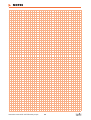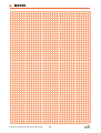
1
Pump models
TR9
T100
TR20
T200
T50
T400
PE & PTFE series
English
Instruction manual
Air operated diaphragm pumps
Edition 3/2004
C:\arbetsfiler\instruktioner\tapflo\pumpar\pe & ptfe eng\instruction peptfe series english.pmd
Pumps in polyethylene or PTFE
Instructions for installation, start up, operation,
maintenance and repair
Spare parts
STOP
Read this instruction manual carefully, before
you install and operate the pump
CONTENTS
CE CERTIFICATE
3
0
GENERAL
4
0.1
0.2
Introduction
The waring symbols
4
4
1
INSTALLATION
5
1.1
1.2
1.3
1.4
1.4.1
1.4.2
1.4.3
1.5
1.5.1
1.6
1.7
1.7.1
1.7.2
1.7.3
Receiving inspection
Storage
Foundation
Suction and discharge pipings
Turnable connections
Connection of suction pipe
Connection of discharge pipe
Air connection
Air treatment system
Example of installation
Recommended installations
Flooded
Selfpriming
Submerged
5
5
5
5
5
5
5
5
6
6
7
7
7
7
2
OPERATION
8
2.1
2.1.1
2.1.2
2.1.3
2.1.4
2.1.5
2.2
2.3
2.3.1
2.3.2
2.4
Health and safety
Protection
Environments in danger of explosion
Air pressure
Noise level
Temperature hazards
Before starting the pump
Starting and operating
Dry running
Optimizing the pump lifetime
Pump stopping
8
8
8
8
8
8
8
9
9
9
9
3
MAINTENANCE
3.1
3.1.1
3.2
3.3
3.4
3.5
3.5.1
3.5.2
When the pump is new or reassembled
Performance test
Routine inspection
Complete inspection
Location of faults
Dismantling the pump
Before the dismantling procedure
Mainparts
Instruction manual PE & PTFE series pumps
10
10
10
10
10
10
11
11
11
2
3.5.3
3.5.4
3.6
3.6.1
3.6.2
3.6.3
3.6.4
Housing
Center block
Assembly of the pump
Center block
Suction and discharge connections
Assembling of the main units
Test run
4
SPARE PARTS
4.1
4.2
4.3
4.4
4.5
4.6
Spare parts TR9 and TR20
Spare parts T50 and T100
Spare parts T200 and T400
Stocking recommendation
How to order parts
Pump code
5
DATA
5.1
5.2
5.3
5.4
5.5
Capacity curves
Capacity changes
Dimensions
Technical data
Tightening torques
6
WARRANTY & REPAIR
6.1
6.2
6.3
Returning parts
Warranty
Warranty form
11
11
12
12
12
12
12
13
13
14
15
16
16
16
17
17
17
18
19
19
20
20
20
21
CE CERTIFICATE
Declaration of conformity
Machinery directive 98/37/EC, Annex 2A
Tapflo AB declares that:
Product name:
Models:
Air operated diaphragm pumps
T…
Is in conformity with the essential health and safety requirements and technical
construction file requirements of the EC Machinery directive 98/37/EC with amendments.
Manufacturer:
Tapflo AB
Address:
Filaregatan 4
S-442 34 Kungälv
Sweden
Tapflo AB, september 1st 1999
Börje Johansson
Managing director
Instruction manual PE & PTFE series pumps
3
0. GENERAL
0.1
Introduction
The Tapflo Air Operated Diaphragm Pump range is a complete serie of pumps for industrial
applications. The pumps are designed to be safe simple and easy to use and maintain. The
construction is sealless and without rotating parts. The pumps are suitable for almost all different
chemicals used by the industry today..
With proper attention to maintenace, Tapflo Pumps will give efficient and trouble free operation.
This instruction manual will familiarise operators with detailed information about installing, operating and maintaining the pump.
0.2
The warning symbols
The following warning symbols are present in this instruction manual. This is what they say.
STOP
!
This symbol stands next to all safety instructions in this instruction manual where danger
to life and limb may occur. Observe these instructions and proceed with utmost caution
in these situations. Inform also other users of all safety instructions. In addition to the
instructions in this instruction manual, the general safety and accident prevention
regulations must be observed.
This signal stands at points in this instruction manual of particular importance for
compliance with regulations and directives, for correct work flow and for the prevention
of damage to and destruction of the complete pump or its subassemblies.
Instruction manual PE & PTFE series pumps
4
1. INSTALLATION
1.1
Receiving inspection
Although precaution is taken by us when packing and shipping, we urge you to carefully check the
shipment on receipt. Make sure that all parts and accesories listed on the packing list are accounted
for. Immediately report any damage or shortage to the transport company and to us.
1.2
!
1.3
!
1.4
Storage
If the equipment is to be stored prior to installation, place it in a clean location. Do not remove the
protective covers from the suction, discharge and air connections which have been fastened to
keep pump internals free of debris. Clean the pump thoroughly before installation.
Foundation
The pump is furnished with vibration absorbing rubber feet. The pump will operate properly without
being fixed to a foundation. If fixation is needed for an installation, make sure the foundation is able
to absorb vibrations. It is essential for the operation of the pump to mount the pump with the feet in
a downward direction (see sketch).
Suction and discharge pipings
Suction and discharge piping should be fully supported and anchored near to but independent of
the pump. The piping to the pump should be a hose, to prevent undue stress and strain on the
pump connections and the pipings.
1.4.1
Turnable connections
The suction and discharge connections are turnable 180°. This simplifies the assembling and
installation considerably. If you wish to turn the connections, screw a threaded nipple into the
connection and turn. On the larger models T200 and T400 it will simplify if the housing nuts are
slightly released while turning the connections.
1.4.2
Connection of suction pipe
Remember that the suction pipe/connection is the most critical point, especially if the pump is
priming. Just a small leakage will dramatically reduce the suction capability of the pump. When
connecting the suction pipe, following is recommended.
1) For satisfactory operation, use reinforced hose or corresponding (the suction power may
otherwise shrink the hose). The internal diameter of the hose should be the same as on the
suction connection (at the bottom of the pump) to have best suction capability.
2) Make sure that the connection hose - pump is completely tight, otherwise the suction capability
will be reduced.
3) Always use as short suction pipe as possible. Avoid air pockets which can arise with long
pipings.
1.4.3
STOP
Connection of discharge pipe
For this connection it is only recommended a simple and positive flow connection. Use a hose or
flexible piping (minimum one meter) between the discharge connection and any rigid fixed piping.
Coil the hose at least one turn. All components (hose, pipe, valves etc) on the discharge piping
must be designed for minimum PN 10.
1.5
Air connection
Screw the air hose into the air intake on the center block of the pump with for example a bayonet
coupling. For best efficiency, use the same hose diameter as the internal diameter of the connection
on the air intake.
Instruction manual PE & PTFE series pumps
5
1. INSTALLATION
1.5.1
!
Air treatment system
The air valve is constructed for oilfree air. Lubrication of the air is not allowed. However, if the air
is very dry (laboratory air), the air may be lubricated with water. Maximum air pressure is 8 bar. As
prevention purpose, a filtration of the air by means of a 5 micron filter or finer is recommended. Dirt
in the air can under unfortunate circumstances be the cause of breakdown.
To facilitate the operation of the pump we recommend an air treatment system connected to the air
supply. These components should be included:
1)
2)
3)
4)
Regulator to adjust the air pressure
Manometer to read the actual pressure
Needle valve to adjust the air flow
Filter
These components are included in Tapflos Air treatment system which can be ordered from us.
1.6
Example of installation
1)
2)
3)
4)
5)
6)
7)
8)
9)
Gate valve compressed air
Filter and pressure regulator
Flexible hose
Needle valve
Flexible piping
Gate valve suction
Gate valve discharge
Coiled flexible piping
Flow gauge
Instruction manual PE & PTFE series pumps
6
1. INSTALLATION
1.7
Recommended installations
The Tapflo pump is flexible in the way you are able to install it. The in- and outlet ports are infinitely
turnable more than 180° to fit various piping systems.
1.7.1
!
Flooded
The piping system is designed with a positive
suction head. This is the best way of installtion
where it is necessary to completely evacuate
all liquid from the container, or where viscous
(thick) products are transfered.
Important
Do not exceed 0,7 bar suction pressure. Higher
pressure may cause premature diaphragm
failure and irregular pump operation.
1.7.2
Selfpriming
The Tapflo pump is designed to pull a high
vacuum. It is able to evacuate an empty suction
pipe without any damage to the pump. The
suction lift is up to 5 meter (16.4 ’) from an
empty suction pipe and up to 8 meter (26.2’)
from a wetted pipe. The suction capability
depends on the pump size (see chapter 5.4)
1.7.3
Submerged
All Tapflo pumps may be submerged into the
liquid. It is important to make sure that all
components which are in contact with the liquid
are chemically compatible. The air exhaust
must be led to the athmosphere by means of a
hose.
Air exhaust port dimension
Pump size
Air exhaust port
TR9, TR20 and T50
T100, T200 and T400
1/2" BSP
1" BSP
Instruction manual PE & PTFE series pumps
7
2. OPERATION
2.1
Health and safety
The pump must be installed according to local and national safety rules.
STOP
2.1.1
STOP
2.1.2
STOP
The pumps are constructed for particular applications. Do not use the pump on applications
different from that for which it was sold without consulting us to ascertain its suitability.
Protection
In the interest of health and safety it is essential to wear protective clothing and safety goggles
when operating, and/or working in the vicinity of Tapflo pumps.
Environments in danger of explosion
The standard PE or PTFE series pumps are not allowed to operate in environments in danger of
explosion. Static electricity may occur in the pump under operation, which may cause explosion
and injury. Special conductive pumps TX are available for such applications. If you have purchased a
TX pump, also carefully read the ATEX instruction appendix. Consult us for further information. Follow
the explosion safety rules applicable at the location for the pump.
2.1.3
Air pressure
The maximum air pressure for Tapflo pumps is 8 bar. Higher air pressure than 8 bar can damage
the pump and may cause injury to personel in vicinity of the pump. If you intend to apply a higher air
pressure than 8 bar, please consult us.
2.1.4
Noise level
At tests, the noise level from a Tapflo pump has not exceeded 80 dB(A). Under some circumstances,
for example if the pump is operating under high air pressure at low discharge head, the noise can
be inconvenient or hazardous for personel staying for long periods in vicinity of the pump. This
hazard can be prevented by:
STOP
- using suitable ear protection
- lower the air pressure and/or raise the discharge head
- lead the outcomming air from the place by connecting a hose from the muffler connection of the
pump. You will find the air exhaust dimension in chapter 1.7.3.
- use elastomer valve balls (EPDM, NBR or polyurethane) instead of PTFE, ceramic or stainless
steel, provided that the elastomer is compatible with the pumped liquid.
2.1.5
Temperature hazards
Raised temperature can cause damage on the pump and/or pipings and may also be hazardous
for personel in the vicinity of the pump/pipings. Avoid quick temperature changes and do not exceed
the maximum temperature specified when the pump was ordered. See also general max temperatures based on water in chapter 5 "Data".
2.2
Before starting the pump
-
Make sure the pump is installed accordning to the installation instruction (section 1).
-
Filling of the pump with liquid before start is not necessary.
-
When installation is new or reinstalled, a test run of the pump with water should be conducted to
make sure the pump operates normally and does not leak.
STOP
Instruction manual PE & PTFE series pumps
8
2. OPERATION
2.3
Starting and operating
-
Open the discharge valve.
-
Note! Considering the suction capacity when air is still in the suction pipe, it is
recommended to start with low air pressure/flow in the beginning. This is not necessary
if the pump is filled with liquid before start.
-
When the pump has been filled with liquid, the air pressure/flow may be raised to increase the
suction capacity of the pump.
-
The performance of the pump can be adjusted through the air supply by using a needle valve
and a pressure regulator. The performance can also be adjusted by normal flow control on the
discharge side of the system.
2.3.1
Dry running
The pump may run dry without any problem.
2.3.2
Optimizing the pump lifetime
Running at full frequenzy (maximum air pressure/flow) continiously will cause premature wear of
the components. As a general rule, we recommend to run at half of the maximum capacity of the
pump. For instance, a T100 pump should run continious maximum at 50 l/min.
2.4
Pump stopping
The pump can be stopped in two ways:
1) Close the discharge valve. The pressure from the system will stop the pump automatically. This
will not do any damage to the pump. The pump restarts easy when the valve is opened again.
2) Stop the air supply.
Instruction manual PE & PTFE series pumps
9
3. MAINTENANCE
3.1
!
3.1.1
3.2
!
3.3
!
When the pump is new or reassembled
If the pump is new or reassembled after maintenance it is important to retighten the pump housing
nuts (pos 37) after a few days of operation. Make sure to use the right torque, see chapter 5.5.
Performance test
When installation is new, a test run of the pump should be conducted. Gauge the capacity at specific
air pressure/flow. This information is for use in checking performance as wear takes place. You will
be able to set schedules for maintenance of the pump and to select spare parts to be kept on stock.
Routine inspection
Frequent observation of the pump operation is recommended to detect problems. A change in sound
of the running pump can be an indication of weared parts (see below "location of faults"). Leaking
liquid from the pump and changes of performance may also be detected. Routine inspections should
be conducted frequently.
Complete inspection
The intervals for a complete inspection depend upon the operation conditions for the pump. The
characteristics of the liquid, temperature, materials used in the pump and running time decide how
often a complete inspection is necessary.
If a problem has occured, or if the pump is in need of a complete inspection, see later this chapter
"location of faults" and "dismantling of the pump". You are of course warmly welcome to consult us
for further help.
Worn parts should be carried in stock, see our recommendation in chapter 4.4.
3.4
Location of faults
Problem
Possible fault
The pump does not run
The air pressure is to low
The air connection is blocked
Muffler is blocked
Air valve is defect
Dirt in the pump chamber
Diaphragm breakdown
The suction is bad
Suction connection is not tight
Suction connection is blocked
Muffler is blocked
Valve balls are blocked
Valve balls are damaged
The pump runs irregularly
Valve balls are blocked
Sealings are defect in air valve or center block
Diaphragm breakdown
Bad flow/pressure
Pressurefall in incomming air
Suction or air connection blocked
Muffler is blocked
Air valve is defect
Valve balls worn out/broken
Air in liquid
Diaphragm breakdown
Liquid leaks from the pump
Screws on the housing not properly fastened
Liquid comes out of the muffler
Diaphragm breakdown
Instruction manual PE & PTFE series pumps
10
3. MAINTENANCE
3.5
Dismantling the pump
The numbers put in brackets, refer to the part numbers in the spare part drawings and spare part
lists in chapter 4.
3.5.1
STOP
Before the dismantling procedure
Be sure to drain all liquid from the pump. Cleanse or neutralize the pump thoroughly. Disconnect
the air connection and then the suction and discharge connections.
3.5.2
Mainparts
1) Unscrew the nuts (37) on one side of the housing (11).
2) Place the pump on the side that still has the nuts (the pump lays on the nuts) on a stable
ground, for example a table.
3) Carefully remove the "loose housing" (11).
4) Carefully lift up the suction and discharge connections (13). You have the center block (12) and
one of the housings with pin screws (14) left.
5) Upend the pump and carefully pull out the pin screws (14). Be careful with the diaphragms (15)
that easily can be damaged by the threads of the pin screws.
The mainparts of the pump are now dismantled. The following is for dismantling the housing and
center block in detail.
3.5.3
Housing
1) Put the house wall with the flat side down on a plane surface that will not damage the housing,
for example a table covered with cardboard.
2) Remove the spacer sleeve (19), by turning it 180°. To do that, put a piece of plastic towards one
side of the spacer sleeve - knock on it so that the spacer sleeve is turning. Then put one of the
pin screws in the hole on the spacer sleeve and turn it as far as it is possible, until it lays upside
down (180°) compared to the starting position. Pull the spacer sleeve carefully against the
lower valve seat (21) until it is free and can be put out. Please note that force never shall be
used for dismantling.
3) Stick something not pointed (for example a pin screw with one of the nuts on) into the hole for
the discharge connection and press gently out the upper valve seat (20).
4) Place one of the pin screws on the inside (behind) the valve ball stopper on the lower valve seat
(21). Carefully pull out the valve seat in the housing.
5) In order to remove the valve ball (23) from the valve seat, use a pin screw and press carefully
out the valve ball stopper (22) and the valve ball will be free.
3.5.3.1
For TR9 and TR20
Dismantling of the spacer sleeve:
Screw a pin screw into the spacer sleeve, pull it up and then out from the housing.
3.5.4
Center block
1) Press the diaphragms (15) to their neutral position (both have the same distance to the center
block).
2) Hold one of the diaphragms (15) and unscrew the other. Then pull out the remaining diaphragm
with the diaphragm shaft (16).
Instruction manual PE & PTFE series pumps
11
3. MAINTENANCE
3) Dismantle the circlips (27) which keep the air valve (61) on it's place, press out the air valve with
for instance a wood shaft of a hammer or by means of a pressing device. Always be careful, so
that you do not damage the sealing edges towards the diaphragm or the air valve.
4) If the shaft sealings (36) seem to be worn out (by internal leakage of air), carefully remove them
with a pointed tool. During this operation, the sealing (36) and backup o-ring (47) usually get
destroyed, so make sure to have replacement spares available.
The pump is now completely dismantled. Check all components for wear or damage and replace if
necessary.
3.6
Assembly of the pump
3.6.1
Center block
1) Mount the circlip (27) on one side. Put some soft soap solution on the air valve o-rings (30) and
then carefully push the air valve (61) into the housing. On the bigger pumps, it is necessary to
use a pressing device for this operation. Make sure that the o-rings (30) remain in the right
position. Put the circlip (27) on the other side.
2) Put the diaphragm (15) with shaft (16) into the center block. Screw the next diaphragm (15) onto
the shaft (16) and fix the holes. Sometimes you have to turn the diaphragms a little back to get
the holes fixed.
3.6.2
Suction/discharge connections
Always make sure that the o-rings (18) are placed on the in/outlet (13) before all assembling of
pump.
Special for pump with PTFE diaphragms:
U-rings (18) are placed on the pump housing. Put u-ring with open side up so you carefully can put
the o-ring in the groove. Make sure you do not fold the inner edge of the u-ring.
3.6.3
Assembling of the main units
1) Turn the housing (11) with the flat side up.
2) Make sure all pin screws (14) have one nut (37) and one washer (38) each. Nut should only be
put on one or two threads.
3) Put all the pin screws through the housing and then turn the housing so it rests on the nuts.
4) Let the center block (12) gently be put to the housing with screws through center block. Be
careful that threads on screws do not damage the diaphragms when assembling.
5) Place suction and discharge connections (13) in their positions in the housing. Be careful not to
damage the u-ring (PTFE model) and o-rings (18).
6) Put the second housing (11) onto the pin screws (14). Make sure that suction/discharge
connections are in right direction and again be careful with the u-ring/o-rings.
7) Fasten the nuts (37) alternatingly by hand, with or without washers depending on how much of
the thread comes out. When all nuts are fastened, turn them gently with a tool so that the pump
gets closed. If some of the nuts were fastened without washer, unscrew thoose and put washers
underneath. See recommended tightening torques in chapter 5. After a few weeks operation a
follow up draft of the nuts is recommended.
3.6.4
Test run
We recommend you to conduct a test run of the pump before installing it to the system so no liquid
gets wasted if the pump leaks or perhaps does not start according to wrong assembling of the
pump.
Instruction manual PE & PTFE series pumps
12
4. SPARE PARTS
4.1
Spare parts TR9 and TR20
Pos
Description
11
12
13
14
15
17
18
19
20
21
22
Housing
Center block
In/Outlet
Pin screw
Diaphragm
Rubber foot
O-ring set (in/outlet)
Spacer sleeve
Lower rod
Upper rod
Pin
Qty/pump
Instruction manual PE & PTFE series pumps
2
1
2
4
2
4
4
2
2
2
2
13
Pos
Description
25
27
30
33
37
38
57
61
63
64
65
Muffler
Circlip
O-ring
Plug
Nut
Washer
Nut cover
Air valve complete
Drum inlet
Pump tube
Handle
Qty/pump
1
2
6
2
8
8
8
1
1
1
1
4. SPARE PARTS
4.2
Spare parts T50 and T100
Pos
Description
11
12
13
14
15
16
17
18
19
20
21
22
23
25
Housing
Center block
In/Outlet
Pin screw
Diaphragm
Diaphragm shaft
Rubber foot
O-ring set (in/outlet)
Spacer sleeve
Upper valve seat
Lower valve seat
Valve ball stop
Valve ball
Muffler
Qty
2
1
2
6
2
1
4
4
2
2
2
4
4
1
Pos
Description
26
27
30
33
36
37
38
43
47
57
61
63
64
65
Air intake adapter
Circlip
O-ring
Plug
Center block sealing
Nut
Washer
O-ring (valve seat)
O-ring (back up for 36)
Nut cover
Air valve complete
Drum inlet
Pump tube
Handle
* = on T50, ** = on T100
Instruction manual PE & PTFE series pumps
14
Qty
1
2
6
2
2
12
12
4
2*/4**
12
1
1
1
1
4. SPARE PARTS
4.3
Spare parts T200 and T400
Pos
Description
11
12
13
14
15
16
17
18
19
20
21
22
23
Housing
Center block
In/Outlet
Pin screw
Diaphragm
Diaphragm shaft
Rubber foot
O-ring set (in/outlet)
Spacer sleeve
Upper valve seat
Lower valve seat
Valve ball stop
Valve ball
Instruction manual PE & PTFE series pumps
Qty
2
1
2
8
2
1
4
4
2
2
2
4
4
15
Pos
Description
Qty
25
26
27
30
33
36
37
38
43
47
57
61
Muffler
Air intake adapter
Circlip
O-ring
Plug
Center block sealing
Nut
Washer
O-ring (valve seat)
O-ring (back up for 36)
Nut cover
Air valve complete
1
1
2
6
2
2
16
16
4
2
16
1
4. SPARE PARTS
4.4
Stocking recommendation
Even at normal operation some details in the pump will be subject to wear. In order to avoid
expensive breakdowns we recommend having a few spare parts in stock.
Depending on the severity of the operation and the importance of not having a breakdown we offer
two different spare part sets.
Set No 2
Set No 1
Qty
2
4*
2+2**
1
4
Description
Diaphragm
Valve ball
Rod valve
Muffler
O-ringset
Pos
Qty
15
23
20, 21
25
18
1
1*
2*
2*
2
2**/4*
2
2*
4*
2*/4***
1
* = Only T50 up to T400
** = Only TR9 and TR20
*** = Only T100
4.5
Description
Pos
Spare part set No 1
Diaphragm shaft
Upper valve seat
Lower valve seat
Spacer sleeve
Pin
Circlip
Center block seal
O-ring valve seat
O-ring
Air valve complete
16
20
21
19
22
27
36
43
47
61
How to order parts
When ordering spare parts for Tapflo Pumps, please let us know the model number from the
nameplate of the pump. Then just indicate the part numbers (refered to the spare part list) and
quantity of each item.
4.6
Pump code
The model number on the pump tells the pump size and material of the pump components.
Tapflo diaphragm pump
Max capacity (l/min)
T
RD
Special execution:
A = Aluminium centerblock
B = Backup diaphragm system
D = Drum pump
E = Valve seat insert (PU, PTFE or
AISI 316)
F = Filterpress pump
G = Cast iron centerblock
H = Pump with housing
reinforcement plates
K = Short shaft version
L = Draining system
M = Optional connection type
N = FEP o-rings (pos 18)
Q = Special sealed pump
R = Rod valves
S = AISI 316/FKM air valve
T = Twin pump
V = AISI 316L valve seat / spacer
X = ATEX approved, group II, cat 2
Z = Semiconductor industry pump
Instruction manual PE & PTFE series pumps
20
Material of wetted thermoplastic
parts:
P = PE (polyethylene)
T = PTFE
P
T
Material of diaphragms:
E = EPDM
N = NBR (nitrile rubber)
T = PTFE
V = FKM (TR9 only)
16
P
Material of valve balls:
E = EPDM
N = NBR (nitrile rubber)
T = PTFE
S = AISI 316 stainless steel
P = PU (polyurethane)
K = Ceramic
Material of rod valves
(TR9 and TR20 only)
P = PE (polyethylene)
T = PTFE
5. DATA
5.1
Capacity curves
The performance curves are based on water at 20°C.Other circumstances might change the
performance.See below how the capacity will change at different viscosities and suction lifts.
Example (see the orange coloured line):
A flow of 6 liter/minute is desired. The discharge pressure is calculated to 4 bar. We choose a TR9.
It requires an air pressure of 6 bar and will consume approximately 0.085 m3 air per minute.
5.2
TR9
TR20
T50
T100
T200
T400
Capacity changes
Capacity changes at different viscosities
Capacity changes at different suction lifts
Instruction manual PE & PTFE series pumps
17
5. DATA
5.3
Dimensions
Standard pumps T
Dimensions in mm (where other is not indicated)
Dimensions in inch (where other is not indicated)
Dim
A
A2
B
B2
B3
C
D
D2
D3
D4
E
E2
E3
F
F2
G
H
H2
I
J
J2
K
L
M
N
P
R
S
ØT
U
V
Pump size
9
20
50
100
200
400
70
105
150
200
270
350
2.76
4.13
5.91
7.87
10.63 13.78
150
300
300
404
5.91
11.81 11.81 15.91
94
112
160
214
310
380
3.70
4.41
6.30
8.43
12.20 14.96
168
221
320
390
6.61
8.70
12.60 15.35
277
391
490
598
10.91 15.39 19.29 23.54
115
135
190
250
345
425
4.53
5.31
7.48
9.84
13.58 16.73
123
168
243
320
450
563
4.84
6.61
9.57
12.60 17.72 22.17
175
250
325
6.89
9.84
12.80
385
550
700
770
15.16 21.65 27.56 30.31
343
477
630
690
13.50 18.78 24.80 27.17
92
132
190
252
345
440
3.62
5.20
7.48
9.92
13.58 17.32
147
210
280
5.79
8.27
11.02
250
333
467
588
9.84
13.11 18.39 23.15
8
8
15
15
30
30
0.31
0.31
0.59
0.59
1.18
1.18
15
21
21
0.59
0.83
0.83
9
15
17
30
30
30
0.35
0.59
0.67
1.18
1.18
1.18
10
15
16
30
30
30
0.39
0.59
0.63
1.18
1.18
1.18
19
33
35
35
0.75
1.30
1.38
1.38
12
15
20
28
38
48
0.47
0.59
0.79
1.10
1.50
1.89
1/4”
3/8”
1/2”
1”
1 1/2”
2”
1/4
3/8
1/2
1
1 1/2
2
1/4”
3/8”
1/2”
3/4”
1”
1 1/2”
1/4
3/8
1/2
3/4
1
1 1/2
M4x20 M4x20 M8x25 M8x25 M8x25 M8x25
M4
M4
M8
M8
M8
M8
1/8”
1/8”
1/4”
1/4”
1/2”
1/2”
1/8
1/8
1/4
1/4
1/2
1/2
15
17
25
38
54
70
0.59
0.67
0.98
1.50
2.13
2.76
58
81
115
154
211
268
2.28
3.19
4.53
6.06
8.31
10.55
35
52
80
105
143
183
1.38
2.05
3.15
4.13
5.63
7.20
0°
0°
15°
15°
0°
0°
0°
0°
15°
15°
0°
0°
13
15
21
27
35
42
0.51
0.59
0.83
1.06
1.38
1.65
20
33
33
0.79
1.30
1.30
1270* 1270* 1270*
50.0* 50.0*
50.0*
285
360
400
11.22 14.17 15.75
* = Any length up to 2000 mm upon request
* = Any length up to 79” upon request
Instruction manual PE & PTFE series pumps
18
Drum pumps TD
Twin pumps TT
Filterpress pumps TF
5. DATA
5.4
Technical data
Data
Pump size
50
100
9
20
General characteristics
*Max capacity (l/min) / (US gpm)
**Volume per stroke (ml) / (cu in)
Max discharge pressure (bar) / (psi)
Max air pressure (bar) / (psi)
Max suction lift dry (m) / (Ft)
Max suction lift wet (m) / (Ft)
Max size of solids (ø in mm) / (in)
Max temp, pump in PE (°C) / (°F)
Max temp, pump in PTFE (°C) / (°F)
Min temperature (°C) / (°F)
9 / 2.4
7 / 0.43
8 / 116
8 / 116
1/3
8 / 26
2 / 0.08
70 / 158
100 / 212
-20 / -4
20 / 5.3
25 / 1.53
8 / 116
8 / 116
1.5 / 5
8 / 26
3 / 0.12
70 / 158
100 / 212
-20 / -4
50 / 13.2
120 / 7.32
8 / 116
8 / 116
3/9
8 / 26
4 / 0.16
70 / 158
100 / 212
-20 / -4
100 / 26
280 / 17.1
8 / 116
8 / 116
4 / 13
8 / 26
6 / 0.24
70 / 158
100 / 212
-20 / -4
Weight
Standard pump T in PE (kg) / (Ib)
Standard pump T in PTFE (kg) / (Ib)
Drum pump TD in PE (kg) / (Ib)
Drum pump TD in PTFE (kg) / (Ib)
Filterpress pump TF in PE (kg) / (Ib)
1 / 2.2
1.5 / 3.3
-
1,5 / 3.3
2.5 / 5.5
2 / 4.4
3.5 / 7
-
5 / 11
7 / 15
6 / 13
9 / 19
8 / 17
10 / 22
17 / 38
11 / 24
18 / 40
Material of components
Pump housing and all wetted
thermoplastic details
Centre block (not wetted)
Diaphragms
Valve balls
Rod valves (TR9 and TR20)
Air valve
O-rings (wetted)
Housing pin screws
Diaphragm shaft
Drum handle (TD pumps)
Reinforcement plates (TF pumps)
200
400
200 / 53
400 / 106
1100 / 67.1 3200 / 195.3
8 / 116
8 / 116
8 / 116
8 / 116
5 / 16
5 / 16
8 / 26
8 / 26
10 / 0.39
15 / 0.59
70 / 158
70 / 158
100 / 212
100 / 212
-20 / -4
-20 / -4
24 / 53
44 / 97
37 / 82
44 / 97
90 / 199
66 / 146
PE or PTFE
PP
PTFE
PTFE, EPDM or NBR
PTFE, EPDM, NBR, AISI 316, PU, Ceramic
PE or PTFE
Brass / NBR or optional AISI 316L / FKM
EPDM, PTFE or FKM
Stainless steel AISI 304
Stainless steel AISI 304
Stainless steel AISI 316L
Stainless steel AISI 316L
* = Recommended flow is half of the the max flow, i.e. recommended flow for a T100 is 50 l/min (13.2 US gpm).
** = The value is based on pumps with EPDM diaphragms. Pumps with PTFE diaphragms have about 15% less volume.
5.5
Tightening torques
The following tightening torques are recommended.
Pump size
TR20
T50
T100
T200
T400
Mounting torque (Nm)
5,5
8
16
20
23
Instruction manual PE & PTFE series pumps
19
6. WARRANTY & REPAIR
6.1
Returning parts
When returning parts to Tapflo AB please follow this procedure:
-
Consult Tapflo AB for shipping instructions.
-
Cleanse or neutralize and rinse the part/pump. Make sure the part/pump is completely empty
from liquid.
-
Pack the return articles carefully to prevent any damage under transport.
Goods will not be accepted unless the above procedure has been complied with.
6.2
Warranty
Tapflo AB warrants products* of it's own manufacture will be free from defects in raw material and
manufacture under normal use and service for a period of not more than one year. Tapflo's obligation under this warranty being limited to repair or replacement of its products which shall be returned to Tapflo AB. Follow the procedures above "returning parts". If a pump or part is received
defected, report to Tapflo AB immediately. Parts returned to our company must have written
authorisation from Tapflo AB. This warranty will not apply to any of our products which shall have
been used other than for their intended use.
* Even when products such as diaphragm pumps operate under normal conditions, some parts are subject to
wear and may have to be replaced within one year. Examples of such parts in Tapflo diaphragm pumps are;
diaphragms, valve balls, o-rings and gaskets etc. This warranty will not apply to these parts being subject to
wear.
Instruction manual PE & PTFE series pumps
20
6. WARRANTY & REPAIR
6.3
Warranty form
Company:
Telephone:
Fax:
Address:
Country:
Contact name:
E-mail:
Delivery date:
Pump was installed (date):
Pump type:
Serial No (stamped on the pump housing):
Description of the fault:
The installation
Liquid:
Temperature (°C):
Contents of particles:
Flow (l/min):
%, of max size (mm):
Duty (h/day):
Discharge head (mwc):
Air pressure (bar):
Spec. grav. (kg/m3):
Viscosity (cPs):
No of starts per day:
Suction head/lift (m):
Quality of the air (filter, micron?, lubrication?):
Other:
Place for sketch of the installation
Instruction manual PE & PTFE series pumps
21
pH-value:
NOTES
Instruction manual PE & PTFE series pumps
22
NOTES
Instruction manual PE & PTFE series pumps
23
Tapflo AB · Filaregatan 4 · S-442 34 Kungälv · Sweden
Tel (46) 303 63390 · Fax (46) 303 19916 · E-mail: [email protected] · www.tapflo.com
DISTRIBUTOR:
All data in this instruction manual are based on the latest product information available at the time of publication. Changes reserved without notice.