1
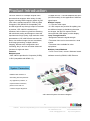
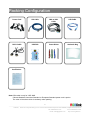
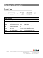
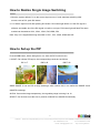
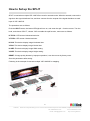
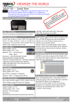
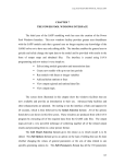
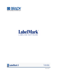
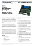
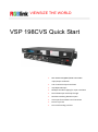
VIEWSIZE THE WORLD VSP 198CVS Quick Start Max 2048×1152@60Hz/2560×1152×50Hz input/output resolution User customize output resolution 3G/HD/SD-SDI input Multiple cascade mapping for super resolution DVI and SDI input with loop through Seamless switching between inputs Auto input format detect and conversion Picture in picture Two install sending card slot CONTENT Packing Configuration ............................................................................................................................ 3 Hardware Orientation .............................................................................................................................. 4 Front Panel ......................................................................................................................................... 4 Back Panel ......................................................................................................................................... 5 Operating Instruction .............................................................................................................................. 6 Content ............................................................................................................................................... 6 How to Realize Single Image Switching ..................................................................................... 7 How to Set up the PIP................................................................................................................. 7 How to Set up the SPLIT ............................................................................................................ 8 How to Set up the Size and Position of the Single Image .......................................................... 9 How to Do Customized Output Resolution ................................................................................. 9 How to Realize the Screen Size and Full Size Switching......................................................... 10 How to Set up Image Zoom ...................................................................................................... 11 How to Realize the Text Overlay Setting .................................................................................. 11 How to Realize Test Pattern Output and Settings .................................................................... 12 How to Set up the Playlist ......................................................................................................... 13 How to Realize LAN Remote Control Settings ......................................................................... 16 How to Save the Parameter ...................................................................................................... 18 How to Load the Saved Parameter........................................................................................... 19 Product Application............................................................................................................................... 20 Multiple Mosaic................................................................................................................................. 20 Contact Information............................................................................................................................... 21 1 Address:S603-604 Weiye Building Torch Hi-Tech Industrial Development Zone Xiamen, Fujian Province, P.R.C Tel: 00865925771197 Fax: 00865925771202 Email: [email protected] http://www.rgblink.cn Product Introduction 1x HDMI,2xVGA, 1 x3G self-adaptive SDI input (3G SDI module), for the application if different signal inputs. Multiple outputs: • 1 x Preview VGA output • 2 X DVI outputs are provided for splitting into two different images or distributing the same two images, the two DVI outputs can be connected with LED display or other display. Loop Through Interface • Designed to boost the signal strength • The same video can be connected to a local monitor • The same video available for other equipments Multiple Control Methods The VSP 198CVS is a multiple outputs video processor that accepts a wide variety of video signals, including RGB computer graphic by DVI, VGA video, standard and HDTV video by HDM. Composite, SDI (SD/HD/3G Compatible), DVI and SDI supports loop through output for cascade or preview. VSP 198CVS combines truly seamless, fade in fade out, glitch-free switching with advanced scaling technologies to meet the requirements of high quality, high resolution video presentations. VSP 198CVS also launches the latest, user defined image size and coordinate, dual image processing, multiple cascade mapping, different user configurations and controlling, Key in and out and other advanced functions for high-end show. Features: Multiple inputs • VSP 198CVS provides 2x Composite (CVBS), 1x DVI (compatible with HDMI 1.3), • Local Front Panel, remote Windows based software control by RS232, USB, Ethernet. System Connection RGBlink offers solutions to demanding technical problems. Any application questions, or required further information, please contact with our customer Support Engineers. VSP 198CVS System Connection Diagram 2 Address:S603-604 Weiye Building Torch Hi-Tech Industrial Development Zone Xiamen, Fujian Province, P.R.C Tel: 00865925771197 Fax: 00865925771202 Email: [email protected] http://www.rgblink.cn Packing Configuration Power Cord SDI Cable DB9 to RJ11 Cable USB Cable DVI-D Cable USB Disk Screw Driver Antistatic Bag Certification Note: SDI cable is only for VSP 198S. Chinese Standard, American Standard or European Standard power cord is option. The color of the screw driver is randomly when packing. 3 Address:S603-604 Weiye Building Torch Hi-Tech Industrial Development Zone Xiamen, Fujian Province, P.R.C Tel: 00865925771197 Fax: 00865925771202 Email: [email protected] http://www.rgblink.cn Hardware Orientation Front Panel Button Instruction CV1, CV2 CVBS signal source button LOAD Load button VGA1,VGA2 VGA signal source button PIP Single and double picture switch button DVI DVI signal source button SPLIT Split button HDMI HDMI signal source button SCALE Scale button SDI SDI signal source button 0~9 Number button, use for scale and custom setting BLACK Black button LCD Panel Show operation menu items MENU Menu and back button Knob Confirm and adjust LCD menu SAVE Save button 4 Address:S603-604 Weiye Building Torch Hi-Tech Industrial Development Zone Xiamen, Fujian Province, P.R.C Tel: 00865925771197 Fax: 00865925771202 Email: [email protected] http://www.rgblink.cn Back Panel Input Interface Other Interface 1. 3 CVBS Input BNC port 7 Dial switch 2. 4 VGA Input DSUB15 port 8 10/100M Interface 5 3G SDI input BNC port 9 USB Interface USB-B port 13 HDMI Input HDMI-A port 10 RS232 Interface 14 DVI Input DVII-I port 11. 19 Sending card interface 12 Power Switch 20 Power IEC-3 Output Interface 6 SDI Loop Out BNC port 15 DVI Loop Out DVI-I port 16. 17 DVI Output DVI-I port 18 VGA Output DSUB15 port 5 Address:S603-604 Weiye Building Torch Hi-Tech Industrial Development Zone Xiamen, Fujian Province, P.R.C Tel: 00865925771197 Fax: 00865925771202 Email: [email protected] http://www.rgblink.cn Operating Instruction Content How to Realize Single Image Switching How to Set up the PIP How to Set up the SPLIT How to Set up the Size and Position of the Single Image How to Do Customized Output Resolution How to Realize the Screen Size and Full Size Switching How to Set up Image Zoom How to Realize the Text Overlay Setting How to Realize Test Pattern Output and Settings How to Set up the Playlist How to Realize LAN Remote Control Settings How to Save the Parameter How to Load the Saved Parameter 6 Address:S603-604 Weiye Building Torch Hi-Tech Industrial Development Zone Xiamen, Fujian Province, P.R.C Tel: 00865925771197 Fax: 00865925771202 Email: [email protected] http://www.rgblink.cn How to Realize Single Image Switching 1. Boot the system default CV1 to the current input source, if need seamless switching other source such as DVI, push DVI button. 2. CV1 button light turns off after pushing DVI button. DVI button light will be on if the DVI signal is effective and stable. And if the DVI signal is invalid or no input, DVI button light will flash.The same method can be switched CV2, VGA1, VGA2, DVI,HDMI, SDI. Note: Only cut is supported among the switch of CV1, CV2, VGA2, HDMI and SDI. How to Set up the PIP Push the PIP button, button led light turn on, enter the PIP function menu. LAYOUT: Can choose PIP layout, the corresponding results are as follows: PIP L+T PBP L+R PBP T+B SWAP IMAGE: It can set PIP to swap exchange, when choose ON, it can realize the IMAGE A and IMAGE B exchange. ALPHA: Can set the image transparency, the regulating range is among 0 to 16. SELECT: Can choose to set the size or position of IMAGE A or IMAGE B individually. 7 Address:S603-604 Weiye Building Torch Hi-Tech Industrial Development Zone Xiamen, Fujian Province, P.R.C Tel: 00865925771197 Fax: 00865925771202 Email: [email protected] http://www.rgblink.cn How to Set up the SPLIT SPLIT is used when multiple VSP 198CVS are used in cascade mode. When do cascade, connect the signals to the signal distributor first, and then connect from the outputs of the signal distributor to each input of VSP 198CVS. The operations are as follows: Push the SPLIT button, the button LED light will turn on, and enter the split function menus. Turn the knob, and choose “SPLIT”, choose “ON” to enable the split function, menus are as follows: H TOTAL: LED screen Horizontal total size. V TOTAL: LED screen Vertical total size. H POS: This device display image Horizontal size. V POS: This device display image Vertical size. H SIZE: This device display image Width setting. V SIZE: This device display image Height setting. RESET: If image quality distorts by improper operation, it can be recover by factory reset. Save the parameters after setting. Following is the example of cascade multiple VSP 198CVS for mapping. 8 Address:S603-604 Weiye Building Torch Hi-Tech Industrial Development Zone Xiamen, Fujian Province, P.R.C Tel: 00865925771197 Fax: 00865925771202 Email: [email protected] http://www.rgblink.cn How to Set up the Size and Position of the Single Image Push the SCALE button, and enter the scale function menus, the OLED module show as follows, user can adjust the following items by knob or number buttons. H SIZE: Width setting. V SIZE: Height setting. H POS: Horizontal phase setting. V POS: Vertical phase setting. RESET: If image quality distorts by improper operation, it can be recover by factory reset. How to Do Customized Output Resolution Push [MENU] button to open the main menu, turn knob and go to <OUTPUT FORMAT>, push knob and confirm to go into the <OUTPUT FORMAT> menu, as following: STANDARD--Standard resolution. CUSTOMIZED--Used defined resolution setting. Push knob and go into <CUSTOMIZED> menu: 1. Turn knob on each digital position, and change the value of the digital by the digital buttons on the front panel. 2. After the digital, push the Knob will add *, means before * is the horizontal size. Same operation for vertical size: 3. After the digital, push the Knob will add @, means before the @ is the vertical size, and after the @ is the refresh rate. Only digital 50 or digital 60 supports for the refresh rate. Use the digital buttons to finish the settings. 4. After input all the values, push knob to enable VSP 198CVS to output this resolution. VSP 198CVS will take 5-10 seconds to enable this output resolution. 9 Address:S603-604 Weiye Building Torch Hi-Tech Industrial Development Zone Xiamen, Fujian Province, P.R.C Tel: 00865925771197 Fax: 00865925771202 Email: [email protected] http://www.rgblink.cn How to Realize the Screen Size and Full Size Switching VSP 198CVS supports the screen parameters to meet the requirement where user want to switch between scale screen size and full display size (like monitor). This is only enable for a single display window. Following is an example of a screen size is1408 x 832. Operator can defined the VSP 198CVS output resolution from standard output resolution list or customized the output resolution which is higher than1408 x 832. For this application 1440x900 is an example: Push the MENU button to go into the main menu, and turn knob goes to <SCREEM PARAMETERS>, push knob and goes into the <SCREEN PARAMETERS> menus as following: H SIZE--Horizontal pixels, turn knob or use the digital button to input the value1408. V SIZE--Vertical pixels, turn knob or use the digital button to input the value 832. H POS--Horizontal position, default value is 0, set the value as the way of H SIZE and V SIZE. V POS--Vertical position, default value is 0, set the value as the way of H SIZE and V SIZE. MODE-- Mode option, choose SCREEN SIZE. 10 Address:S603-604 Weiye Building Torch Hi-Tech Industrial Development Zone Xiamen, Fujian Province, P.R.C Tel: 00865925771197 Fax: 00865925771202 Email: [email protected] http://www.rgblink.cn How to Set up Image Zoom The image can be zoom in horizontal or vertical separately, to meet the special effects required. Push the MENU button to go into the menu items, turn the knob and choose [PICTURE], push the knob to confirm. Turn the knob, and choose “ZOOM”, show the menus as following: V UP--Zoom in vertical and the image will be zoom in to the top direction from its bottom. V DOWN--Zoom in vertical and the image will be zoom in to the down direction from its top. V UP/DOWN--Zoom in vertical but in both top and down direction from its middle. H LEFT--Zoom in horizontal and the image will be zoom in to the left direction from its right. H RIGHT--Zoom in horizontal and the image will be zoom in to the right direction from its left. H LIFT/RIGHT--Zoom in horizontal but in both left and right direction from its middle. CENTER--Zoom in 4 corner direction from center. How to Realize the Text Overlay Setting 1. Push MENU button, rotate the knob, choose [TEXT OVERLAY] and Enter [TEXT OVERLAY], push the knob to confirm. 2. Rotate the knob, choose TEXT OVERLAY mode, choose ON, TEXT OVERLAY function open. 3. Push MENU, return to [TEXT OVERLAY], rotate the knob, OLED screen displays menu options, select 13 modes in PRESET, or select BLEND, which includes two modes: Mode 1: Graphic content locate at the top and is non-transparent, background transparency is controlled by double-image transparency. Mode 2: Graphic content is controlled by double-image transparency, the background is completely transparent. Rotate the knob and choose the mode. 4. Push MENU, return to [TEXT OVERLAY], rotate the knob, choose ABOVE/BELOW to select the layer position for IMAGE B. 5. Push MENU, return to [TEXT OVERLAY], rotate the knob, choose BLEND LEVEL, and set the image 11 Address:S603-604 Weiye Building Torch Hi-Tech Industrial Development Zone Xiamen, Fujian Province, P.R.C Tel: 00865925771197 Fax: 00865925771202 Email: [email protected] http://www.rgblink.cn display transparency, regulating range between 0 - 16. 6. Push MENU, return to [TEXT OVERLAY], rotate the knob, choose the color value: RED: The value range of color RED that to be set, regulating range between 0~255. GREEN: The value range of color GREEN that to be set, regulating range between 0~255. BLUE: The value range of color BLUE that to be set, regulating range between 0~255. 7. At the same time, you can view the effect through the screen, to get a better setting. Note: All the above settings are available only for IMAGE B. How to Realize Test Pattern Output and Settings Test Pattern is used to calibrate the screen or system, especially when there is not standard input measure instrument. There are 66 kinds of test patterns for VSP 198CVS. Push the MENU button and go into the menu items, turn the knob and go to <SYSTEM> menu. Push knob and go into the <SYSTEM> menu. Turn knob and go to <DISPLAY MODE> menu. Push knob and go into the <DISPLAY MODE> menu. Turn knob and go to <FLAT COLOR> or <TEST PATTERN> option. FLAT COLOR: push knob and go into the menu, RED color range is from 0-255, GREEN is from 0-255, and BLUE is from 0-255. TEST PATTERN: Push knob and go into the menu items, there are 66 kinds of test patterns. If choose AUTO SWITCH, VSP 198CVS will output all the test patterns one by one, and the interval between is 1 to10S. 12 Address:S603-604 Weiye Building Torch Hi-Tech Industrial Development Zone Xiamen, Fujian Province, P.R.C Tel: 00865925771197 Fax: 00865925771202 Email: [email protected] http://www.rgblink.cn How to Set up the Playlist Users can set up VSP 198CVS in “Device Schedule” in PC software to play the appointed input video automatically in appointed time and operation of single or dual channels, also can set up the ratio and position. Users can setup up to 10 timing operation in the schedule. 1. First, make sure the VSP 198CVS has been connected to the PC software. 2. Double click the VSP 198CVS software, software interface is shown as follows: 3. Click the [VP Processor] option on the top left, then show the drop-down menu as follows: 4. Choose “Device Schedule” option in the drop-down menu: 13 Address:S603-604 Weiye Building Torch Hi-Tech Industrial Development Zone Xiamen, Fujian Province, P.R.C Tel: 00865925771197 Fax: 00865925771202 Email: [email protected] http://www.rgblink.cn Timer Index: Timer index, currently, users can setup up to 10 timing operation in the schedule. Date Settings: The date timing play appoint. Time: The time timing play appoint. Operating Mode: User can choose single or dual channels. Scale: User can set the image ratio and position for Image 1 and Image 2 (Dual channels). : Automatic play signal source selection. 5. Click set icon to save after setting. 6. If need to get certain timing content, input the timer index, and click the get icon to see the specific content. For example: choose timer index 2, show the interface as follows: 14 Address:S603-604 Weiye Building Torch Hi-Tech Industrial Development Zone Xiamen, Fujian Province, P.R.C Tel: 00865925771197 Fax: 00865925771202 Email: [email protected] http://www.rgblink.cn 7. The software default "Device Schedule" function close, user should click on icon to realize automatically play. 15 Address:S603-604 Weiye Building Torch Hi-Tech Industrial Development Zone Xiamen, Fujian Province, P.R.C Tel: 00865925771197 Fax: 00865925771202 Email: [email protected] http://www.rgblink.cn How to Realize LAN Remote Control Settings Firstly, To realize LAN remote control need to build up a LAN platform including: ①One computer (Laptop or computer, used to do remote control which installed windows control software in the computer, please refer to software installing part for installation software).②One router (Better to have wireless function which may realize WEB control cross different platform, without wireless function is available but only realize cable remote control. No limitation for router’s model and brand, such as VPN router model: Netcore 255 or 266; Volans VE 760W or 982W). ③One VSP 198CVS processor (as long as the router’s network ports can connect to, user can place multi pieces of VSP 198CVS). Step one: LAN physical connection. Connect VSP 198CVS and router with network cable, then connect computer and router with network cable also, use the LAN port of router, LAN port is used for connecting to outer net. Sketch map as below: Step two: IP address setting (processor’s default IP address is 192.168.0.100) Firstly change computer’s local connection to “automatically getting the IP”, showed as below: 16 Address:S603-604 Weiye Building Torch Hi-Tech Industrial Development Zone Xiamen, Fujian Province, P.R.C Tel: 00865925771197 Fax: 00865925771202 Email: [email protected] http://www.rgblink.cn Secondly refer to router’s instruction (user manual specification), and find out router’s default network segment. If router’s default network segment is 192.168.0.1, then it is same to processor IP address segment, open up windows control software and user can directly control on VSP 198CVS. If router’s default network segment is 192.168.1.1, then user need to change router’s default gateway or change processor’s IP, both methods are available, but we suggest to change processor’s IP. Method one: Change processor’s IP. Press MENU on front panel and go into items as below image shows. Change processor’s IP to be 192.168.1.100, confirm and restart the processor, then user can directly control on VSP 198CVS via windows control software. Method two: Change router’s gateway. Type in 192.168.1.1 on the browser and go into router setting. Type in default account and code (please refer to the router user manual for the information); Go to router setting part and find out “LAN port setting”, change the default value “192.168.1.1” to be “192.168.0.1”. Save the setting and restart the router, then user can directly control on VSP 198CVS via windows control software. 17 Address:S603-604 Weiye Building Torch Hi-Tech Industrial Development Zone Xiamen, Fujian Province, P.R.C Tel: 00865925771197 Fax: 00865925771202 Email: [email protected] http://www.rgblink.cn How to Save the Parameter Save user mode to the customer for different scene directly call, leave out the edit operation inconvenience, VSP 198CVS provides ten save preferences. 1. Push the MENU button, the button light is on, and enable the SAVE function. SAVE TO —>SAVE 1 Button is on can be saved Button flashes will be overwrite 2. Turn the knob, and choose the position that will save, push the knob to confirm. 3. The figure: 1, 2, 3, 4, 5, 6, 7, 8, 9, 0 down of the buttons means SAVE1~10, user can push any button on to save. For example, save to SAVE 2, push button 2, the OLED panel will show as follows after saving. SAVE TO —>SAVE 2 FINISHED! Button is on can be saved Button flashes will be overwrite 4. Again push the MENU button, the button light is off, and disable the SAVE function. 18 Address:S603-604 Weiye Building Torch Hi-Tech Industrial Development Zone Xiamen, Fujian Province, P.R.C Tel: 00865925771197 Fax: 00865925771202 Email: [email protected] http://www.rgblink.cn How to Load the Saved Parameter Save user mode to the customer for different scene directly call, leave out the edit operation inconvenience, VSP 198CVS provides ten save preferences. 1. Push the LOAD button, the button light is on, and enable the LOAD function. RECALL SAVE —>SAVE 1 Button on is ready for recall Button flashes means just recall 2. Turn the knob, and choose the position that will load, push the knob to confirm. 3. Again push the LOAD button, the button light if off, and disable the LOAD function. 19 Address:S603-604 Weiye Building Torch Hi-Tech Industrial Development Zone Xiamen, Fujian Province, P.R.C Tel: 00865925771197 Fax: 00865925771202 Email: [email protected] http://www.rgblink.cn Product Application Multiple Mosaic Project 1: Set VSP 198CVS/1# as PIP mode, and output signal to VSP 198CVS/2#, then VSP 198CVS/2# output signal to VSP 198CVS/3# by DVI LOOP OUT, VSP 198CVS/3# output signal to VSP 198CVS/4# by DVI LOOP OUT, VSP 198CVS/4# output signal to VSP 198CVS/5# by DVI LOOP OUT. The split modes, including “FIELD GLYPH”, “HORIZONTAL 1/4”, “VERTICAL 1/4” and “IRREGULAR” can be achieved. Project 2: VSP 198CVS/1# output signal to VSP 198CVS/2#, then VSP 198CVS/2# output signal to VSP 198CVS/3# by DVI LOOP OUT, VSP 198CVS/3# output signal to VSP 198CVS/4# by DVI LOOP OUT, VSP 198CVS/4# output signal to VSP 198CVS/5# by DVI LOOP OUT for cascade. 20 Address:S603-604 Weiye Building Torch Hi-Tech Industrial Development Zone Xiamen, Fujian Province, P.R.C Tel: 00865925771197 Fax: 00865925771202 Email: [email protected] http://www.rgblink.cn Contact Information Warranty: All video products are designed and tested to the highest quality standard and backed by full 3 years parts and labor warranty. Warranties are effective upon delivery date to customer and are non-transferable. RGBlink warranties are only valid to the original purchase/owner. Warranty related repairs include parts and labor, but do not include faults resulting from user negligence, special modification, lighting strikes, abuse(drop/crush), and/or other unusual damages. The customer shall pay shipping charges when unit is returned for repair. Headquarter: S603~604 Weiye Building Torch Hi-Tech Industrial Development Zone Xiamen, Fujian Province, P.R.C ● ● ● ● Tel: +86-592-5771197 Fax: +86-592-5771202 Customer Hotline: 4008-592-315 Web: ~ http://www.rgblink.com ~ http://www.rgblink.cn ● E-mail: [email protected] 21 Address:S603-604 Weiye Building Torch Hi-Tech Industrial Development Zone Xiamen, Fujian Province, P.R.C Tel: 00865925771197 Fax: 00865925771202 Email: [email protected] http://www.rgblink.cn