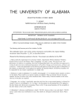
1
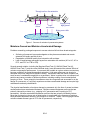
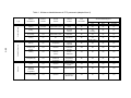
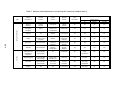
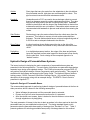
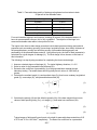
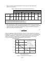
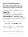
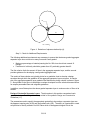
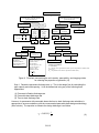
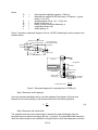
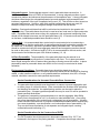
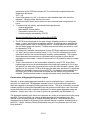
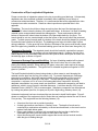
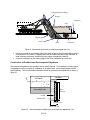
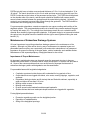
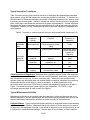
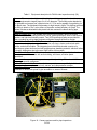
Copy No.
Guide for Mechanistic-Empirical Design
OF NEW AND REHABILITATED PAVEMENT
STRUCTURES
FINAL DOCUMENT
APPENDIX SS:
HYDRAULIC DESIGN, MAINTENANCE, AND
CONSTRUCTION DETAILS OF SUBSURFACE DRAINAGE
SYSTEMS
NCHRP
Prepared for
National Cooperative Highway Research Program
Transportation Research Board
National Research Council
Submitted by
ARA, Inc., ERES Division
505 West University Avenue
Champaign, Illinois 61820
February 2001
SS-i
Acknowledgment of Sponsorship
This work was sponsored by the American Association of State Highway and Transportation
Officials (AASHTO) in cooperation with the Federal Highway Administration and was
conducted in the National Cooperative Highway Research Program which is administered by the
Transportation Research Board of the National Research Council.
Disclaimer
This is the final draft as submitted by the research agency. The opinions and conclusions
expressed or implied in this report are those of the research agency. They are not necessarily
those of the Transportation Research Board, the National Research Council, the Federal
Highway Administration, AASHTO, or the individual States participating in the National
Cooperative Highway Research program.
Acknowledgements
The research team for NCHRP Project 1-37A: Development of the 2002 Guide for the Design of
New and Rehabilitated Pavement Structures consisted of Applied Research Associates, Inc.,
ERES Consultants Division (ARA-ERES) as the prime contractor with Arizona State University
(ASU) as the primary subcontractor. Fugro-BRE, Inc., the University of Maryland, and
Advanced Asphalt Technologies, LLC served as subcontractors to either ARA-ERES or ASU
along with several independent consultants.
Research into the subject area covered in this Appendix was conducted at ARA-ERES. The
authors of this Appendix are Mr. Jagannath Mallela, Leslie Titus-Glover, and Dr. Michael I.
Darter.
Foreword
This appendix is a supporting reference to the subdrainage guidance presented in PART 3,
Chapter 1 of the Design Guide. Some sections of the referenced chapter are repeated here for
emphasis and continuity. Of particular interest are sections on hydraulic design of the drainage
components—permeable bases, separator layers, edgedrains, and outlets—drainage construction,
and maintenance.
SS-ii
APPENDIX SS
HYDRAULIC DESIGN, MAINTENANCE, AND CONSTRUCTION
DETAILS OF SUBSURFACE DRAINAGE SYSTEMS
Introduction
As early as 1820, John McAdam noted that, regardless of the thickness of the structure, many
roads in Great Britain deteriorated rapidly when the subgrade was saturated (1). It is
recognized today that excess moisture in pavement layers, when combined with heavy truck
traffic and moisture-susceptible materials, can reduce service life. Below-freezing temperatures
can contribute to durability problems of saturated materials. Failures related to moistureaccelerated damage continue to take place to this day. In recognition of the impact moisture
can have on pavement performance, the AASHTO Design Guide incorporated an empirical
drainage coefficient into the 1986 design equations. This coefficient increased awareness and
encouraged design of pavements with permeable drainage layers.
The M-E procedures consider the effects of excess moisture on unbound granular and
subgrade layers through reductions in layer moduli. The incremental damage accumulation
approach makes it possible to consider seasonal changes in unbound layers directly. This
approach also makes it possible to consider changes in layer properties over time. These
include the erosion of layers with subsequent loss of support conditions for PCC pavements and
increased infiltration of moisture into AC pavements from cracking over time. However, the
practical considerations of subsurface drainage design are important because not all of these
effects can be considered in the M-E design procedure.
Sources of Moisture in Pavements
It is important to identify the sources of moisture in pavements before devising ways to combat
it. Moisture in the subgrade and the pavement structure can come from many different sources
(see figure 1). Water may seep upward from a high groundwater table due to capillary suction
or vapor movements (2), or it may flow laterally from the pavement edges and side ditches.
Another important source of water in pavements is surface infiltration of rainwater through joints,
cracks, shoulder edges, and various other defects, especially in older deteriorated pavements.
A study by the Minnesota Department of Transportation indicated that 40 percent of rainfall
enters the pavement structure (3). In fact, Demonstration Project 87, Drainable Pavement
Systems, states that surface infiltration is the single largest source of moisture-related problems
in PCC pavements (4). Although AC pavements do not contain joints, they develop cracks,
longitudinal cold joints that crack, and pavement edges that provide ample opportunity for water
to infiltrate the pavement structure and cause damage.
This chapter addresses moisture infiltrating the pavement structure through the surface.
Groundwater seepage is usually considered a geotechnical problem which needs to be
addressed during embankment design and will not be discussed in this Guide.
SS-1
Through surface discontinuities
From edge
Capillary
action
Vapor
movements
Seepage from
high ground
Rising water table
Water table
Figure 1. Sources of moisture in pavement systems.
Moisture-Caused and Moisture-Accelerated Damage
Problems caused by prolonged exposure to excess moisture fall into three broad categories:
•
•
•
Softening of pavement layers and subgrade as they become saturated and remain
saturated for lengthy periods of time.
Degradation of material quality from interaction with moisture.
Loss of bond between pavement layers from saturation with moisture (AC to AC, AC to
PCC, and PCC to CTB or ATB).
Several research studies, including the Maryland Road Test (5), WASHO Road Test (6),
AASHO Road Test (7), and the recent MnRoad study, have documented the adverse effects of
moisture on pavement performance. A pavement that is stable at a given moisture content may
become unstable if the materials approach saturation. High water pressures can develop in
saturated soils when subjected to dynamic loading. Subsurface water can freeze, expand, and
exert forces of considerable magnitude on a pavement. Water in rapid motion can transport soil
particles and cause a number of different problems, including eroding of most materials and
pumping of fines. These potential circumstances must be recognized and accounted for in the
design of a pavement, or it will likely experience moisture-accelerated damage and require high
maintenance and early rehabilitation.
The physical manifestation of moisture damage in pavements is in the form of several moisturecaused and moisture-accelerated distresses. Moisture-caused distresses are those that are
primarily induced by moisture (e.g., stripping in AC pavements and D-cracking in PCC
pavements). Moisture-accelerated distresses are those that are primarily initiated by factors
other than moisture but whose rate of deterioration is accelerated in the presence of moisture.
Most pavement distresses worsen in the presence of moisture. Tables 1 and 2 highlight various
moisture-related distress types in PCC and AC pavements, respectively.
SS-2
Table 1. Moisture-related distresses in PCC pavements (adapted from 8).
Type
Distress
Manifestation
Cracking
SS-3
Surface Deformation
Surface Defects
Spalling
Moisture
Problem
Possible
Yes
Climatic
Problem
Freeze-thaw Cycles
Freeze-thaw Cycles
Scaling
Material
Problem
Structural Defect Begins in
LoadAssociated?
PCC
Base
Subgrade
Mortar
No
Yes
No
No
No
Yes
Finishing
No
No
No
Yes
No
No
D-Cracking
Yes
Freeze-thaw Cycles
Chemical
Influence
Aggregate
Expansion
Crazing
No
No
Rich Mortar
No
Yes
Weak Surface
No
No
Blow-up
No
Temperature
Thermal
Properties
No
Yes
No
No
Pumping and
Erosion
Yes
Moisture
Inadequate
Strength
Yes
No
Yes
Yes
Faulting
Yes
MoistureSuction
ErosionSettlement
Yes
No
Yes
Yes
Curling/Warping
Yes
Moisture &
Temperature
Moisture and
Temperature
Differentials
No
Yes
No
No
Corner
Yes
Moisture
Cracking follows
Erosion
Yes
No
Yes
Yes
Diagonal
Transverse
Longitudinal
Yes
Moisture
Follows Erosion
Yes
No
Yes
Yes
Punchout (CRCP)
Yes
Moisture
High deflections
follow erosion
Yes
No
Yes
Yes
Table 2. Moisture-related distresses in conventional AC pavements (adapted from 8).
Structural Defect Begins in
Surface Deformation
Type
SS-4
Cracking
Distress
Manifestation
Moisture
Problem
Climatic
Problem
Material
Problem
LoadAssociated?
AC
Base/Unbound
Subbase
Subgrade
Bump or
Distortion
Excess
Moisture
Frost Heave
Volume
Increase
No
No
No
Yes
Corrugation
or Rippling
Slight
Moisture and
Temperature
Unstable Mix
Yes
Yes
Yes
No
Stripping
Yes
Moisture
Loss of Bond
No
Yes
No
No
Rutting
Excess in
Granular Layers or
Subgrade
Moisture
Plastic
Deformation,
Stripping
Yes
Yes
Yes
Yes
Depression
Excess Moisture
Suction &
Materials
Settlement, Fill
Material
No
No
No
Yes
Potholes
Excess Moisture
Moisture,
Temperature
StrengthMoisture
Yes
Yes
Yes
Yes
Longitudinal not-inwheel-path and
longitudinal inwheel-path
No (accelerates
crack severity)
No
Construction
No
Faulty
Construction
No
No
Alligator (fatigue)
Yes (accelerates
crack severity)
Spring-Thaw
Strength Loss
Thickness
Yes
Yes, Mix
Yes
Yes
Transverse
No (accelerates
crack severity)
Low Temp,
F-T Cycles
Thermal
Properties
No
Yes, Temp.
Susceptible
No
No
Slippage
Yes
No
Loss of Bond
Yes
Yes, Bond
No
No
Approaches to Address Moisture in Pavements
A major objective in pavement design should be to keep the base, subbase, subgrade, and
other susceptible paving materials from becoming saturated or even being exposed to constant
high moisture levels over time. Four approaches commonly employed to control or reduce
moisture problems are listed below:
•
•
•
•
Prevent moisture from entering the pavement system.
Use materials that are insensitive to the effects of moisture.
Incorporate design features to minimize moisture damage.
Quickly remove moisture that enters the pavement system.
It is important to recognize that no single approach can completely negate the effects of
moisture on the pavement system under heavy traffic loading over many years. Thus, it is often
necessary to employ all approaches in combination, particularly for heavy traffic loading
conditions.
Basic Subsurface Drainage Terminology
This section introduces some of the subdrainage components referred to throughout this
chapter, along with short discussions of their functions and salient characteristics. Detailed
design considerations are addressed later in this chapter.
Permeable Base:
An open-graded drainage layer with a minimum laboratory permeability
value of 1000 ft/day. This layer could be asphalt-treated, cement-treated,
or untreated, depending on structural requirements. The primary function
of this layer is to collect water infiltrating the pavement and to move it to
the edgedrains within an acceptable timeframe. The aggregate used for
the permeable base should be crushed (with at least two mechanically
fractured faces) and wear resistant. Asphalt-treated drainage layers must
be treated with a stiff AC binder to prevent draindown. Additional
specifications on treated open-graded materials can be found in PART I,
Chapter 2 of the Guide. Guide specifications are also available through
the FHWA.
Separator Layer:
An impermeable layer of aggregate material (treated or untreated) or
geotextile or a combination thereof placed between the permeable base
and the subgrade. The separator layer has three main functions: (a) to
maintain separation between permeable base and subgrade and prevent
them from intermixing, (b) to form an impermeable barrier that deflects
water from the permeable base horizontally toward the pavement edge,
and (c) to support construction traffic.
Edgedrains:
Longitudinal pipes that run along the pavement length. They are placed 2
inches from the bottom of a trench dug on the side of the pavement
adjacent to the lane–shoulder joint. They collect water discharged from
the pavement structure and transfer it to the outlets. Pipe edgedrains and
prefabricated geocomposite edgedrains (PGEDs) are the two types of
commonly available edgedrains. Smooth-walled pipes having adequate
strength to withstand loads placed on them are recommended for use as
pipe edgedrains. Pipes should conform to the appropriate State or
AASHTO specification.
SS-5
Outlets:
Short pipes that carry the water from the edgedrains to the side ditches.
Non-perforated smooth, rigid pipes are recommended for outlets. This
pipe must resist construction and maintenance traffic.
Headwall:
Headwalls made of PCC are used to house drainage outlets to prevent
them from damage caused by routine maintenance activities. They also
help prevent slope erosion and aid in locating outlet pipes. Headwalls
should be placed flush with the slope of the embankment so that routine
maintenance activities are not impaired. Removable rodent screens are
recommended with headwalls to prevent small animals from entering the
outlets.
Side Ditches:
Ditches dug to carry the water collected from the outlets away from the
pavement. This feature is common to both surface and subsurface
drainage. The side ditches should have a minimum longitudinal grade of
0.005 m/m and an adequate freeboard to be effective.
Storm Drains:
In urban locations where ditches cannot be dug on the side of the
highway, storm drains are installed to carry the surface and subsurface
runoff.
Daylighting:
In a daylighted pavement section, the edges of the base and subbase
layers are exposed to allow water trapped in these layers to flow directly
into the side ditch. Such a design is the conceptual opposite of a
“bathtub” section.
Hydraulic Design of Permeable Base Systems
The issues involved in designing the main components of a permeable base system are
presented in the following sections. The main topics of discussion are permeable base design,
separator layer design, and edgedrain design. The FHWA microcomputer program DRIP (9)
can perform the hydraulic design of these components rapidly and accurately. This program is
available with the software accompanying the Design Guide. The National Highway Institute
training course 131026, Pavement Subsurface Drainage Design, (10) provides a summary
description of the program, along with an example design. The DRIP 2.0 User’s Guide is
presented in Appendix TT.
Hydraulic Design of Permeable Bases
The recommended approach for performing hydraulic design of permeable bases is the time-todrain procedure, which is based on the following assumptions:
•
•
•
Water infiltrates the pavement until the permeable base is saturated.
Excess runoff will not enter the pavement section after it is saturated.
After the rainfall event ceases, water is drained to the side ditches or storm drains
through edgedrains or by daylighting.
The main parameter of interest in the time-to-drain procedure is the time required to drain the
permeable base to a pre-established moisture level. The design standard based on this
parameter rates the permeable base quality of drainage from “Excellent” to “Poor.” Table 3
presents guidance for selecting permeable base quality of drainage based on this method.
SS-6
Table 3. Permeable base quality of drainage rating based on time taken to drain
50 percent of the drainable water.
Quality of Drainage
Time to Drain
Excellent
Good
2 hours
1 day
Fair
Poor
7 days
1 month
Very Poor
Does not drain
For most Interstate highways and freeways, draining 50 percent of the drainable water in 2
hours is recommended; however, this is only a guideline. The objective of drainage is to
remove all drainable water within a short period of time.
The inputs to the time-to-drain design procedure include basic pavement design and material
properties such as roadway geometry (cross-slope, longitudinal slope, lane width), thickness of
the permeable base, porosity and effective porosity of permeable base aggregate, and
permeability of the permeable base material. Using these inputs, the time-to-drain parameter is
calculated for a given degree of drainage (U). The final design is then chosen on the basis of
this information.
The following is a step-by-step procedure for completing the time-to-drain design.
1. Assume a desired degree of drainage (U). For typical highway situations, U = 0.5.
2. Select a value for the permeable base thickness (H).
3. Determine the coefficient of permeability (k) of the proposed base material through
laboratory testing. Permeable bases should typically have k values of 1000 ft/day or
greater.
4. Calculate the resultant length (LR) and resultant slope (SR) from known roadway longitudinal
grade (S), cross-slope (Sx), and permeable base width (W).
⎡
L R = W ⎢1 +
⎢⎣
2
⎛ S ⎞ ⎤
⎜⎜
⎟⎟ ⎥
⎝ S x ⎠ ⎥⎦
(
S R = S x2 + S 2
1/ 2
)
1/ 2
(1)
(2)
5. Calculate the porosity (N) and the effective porosity (Ne) of the base material from known
values of bulk specific gravity (Gsb), unit weight (γd), and water loss coefficient (WL).
6.
⎞
⎛
γd
⎟⎟
N = ⎜⎜1 −
⎝ 9.81* Gsb ⎠
(3)
Ne = N x WL
(4)
Typical ranges of bulk specific gravity and unit weight for permeable base material are 2.65
to 2.70 and 15.5 to 19.0 kN/m3, respectively. The water loss coefficient for a permeable
SS-7
base is a function of the type and amount of fines present in the base and can be
determined from table 4.
Table 4. Water loss values as a percentage of total water (4).
Material
Type
Type and Amount of Fines
Silt
2.5%
5%
10%
2.5%
2.5%
Filler
5%
10%
Gravel
70
60
40
60
40
20
Sand
57
50
35
50
35
15
Clay
5%
10%
40
30
10
25
18
8
Notes:
Fines are defined as material passing the No. 200 sieve.
For gravel with 0 percent fines, water loss is equal to 80 percent.
For sand with 0 percent fines, water loss is equal to 65 percent.
6. Use either equation 5 or DRIP (9) to determine the time required to remove 50 percent of
the drainable water from the saturated permeable base (U = 0.5). Compare this value to the
target time-to-drain. If the design is unsatisfactory, continue iterations by changing the
inputs until the desired solution is obtained.
N e L2R
t50 =
2k ( S R LR + H )
(5)
Equation 5 represents a single point calculation of the time-to-drain parameter at a degree of
drainage of 0.5. DRIP can be used to compute the time required to drain to any desired degree
of drainage or saturation (S). When DRIP is used to compute the time to drain, time-history
plots from an initial fully saturated state to a completely drained state can be obtained.
Figure 3 is a sample plot of time to drain against the percent drained.
Percent Drained
0
H = 0.15 m
N = 0.3
N e = 0.25
L R = 7.6 m
S R = 0.02 m/m
k = 305 m/day
20
40
60
80
100
0
1
3
Time to Drain, hours
5
Figure 3. Percent drained versus time.
SS-8
7
Sensitivity of the Time-to-Drain Procedure and Permeable Base Design
Recommendations. Of all the inputs that go into the calculations, permeability has the greatest
influence and permeable base thickness the least influence on the time-to-drain parameter. The
time required to drain a permeable base decreases exponentially with an increase in
permeability. Therefore, to reduce the time to drain cost-effectively, it is recommended that the
permeability be increased by a reduction in fines (a minimum of 1000 ft/day is required for
permeable bases). However, care must be taken to maintain adequate stability in the
permeable base while effecting a reduction in fines. To guarantee reasonable stability, a
minimum coefficient of uniformity value, CU, of 3.5 is required for an untreated permeable base.
If this cannot be achieved, the base should be treated with either asphalt or portland cement.
Since the thickness does not have a significant effect on the time-to-drain parameter, a value 4
inches is recommended for permeable bases. This thickness should provide an adequate
hydraulic conduit and lend itself to compaction without segregation.
Separator Layer Design
The issues involved in designing the two types of separator layers—dense-aggregate and
geotextile—will be discussed in this section. If a combination of these layers is to be used due
to adverse site conditions (see table 3 to determine when this might be necessary), it is
recommended that the geotextile be placed on top of the separator layer.
Design of Aggregate Separator Layer. The aggregate separator layer must satisfy the
uniformity and separation requirements at both the separator layer/subgrade interface and the
separator layer/permeable base interface. The separator layer should serve as an impermeable
barrier to prevent the water in the permeable base from entering the subgrade (permeability less
than 15 ft/day is desired). The aggregate separator layer design is a three-step process.
Step 1: Check for Aggregate Separator Layer/Subgrade Interface Requirements
The gradation of the aggregate separator layer must meet the requirements for the aggregate
separator layer/subgrade interface listed below:
Separation requirement:
Uniformity requirement:
D15 (Separator Layer) < 5 D85 (Subgrade)
D50 (Separator Layer) < 25 D50 (Subgrade)
DX represents the particle size that x percent of the material is small than by weight.
Theoretically, a spherical particle will be retained until the diameter of the retaining spheres is
6.46 times greater than the sphere to be retained. This relationship is shown in figure 4. By
limiting the D15 size of the aggregate separator layer to less than 5 times the D85 size of the
subgrade, the larger soil particles of the subgrade will be retained, allowing the soil bridging
action to start. By limiting the D50 size of the aggregate separator layer to less than 25 times the
D50 size of the subgrade, the gradation curves will be kept in balance.
Step 2: Check for Aggregate Separator Layer/Permeable Base Interface Requirements
Similar requirements must be applied to the permeable base/aggregate separator layer
interface, as listed below:
Separation requirement: D15 (Permeable Base) < 5 D85 (Separator Layer)
Uniformity requirement: D50 (Permeable Base) < 25 D50 (Separator Layer)
SS-9
DS
D
D = 6.46 DS
Figure 4. Retention of spheres relationship (4).
Step 3: Check for Additional Requirements
The following additional requirements are necessary to ensure that the dense-graded aggregate
separator layer does not have too many fines and is well-graded:
•
•
Maximum percentage of material passing the No. 200 sieve should not exceed 12
percent.
Coefficient of uniformity should be greater than 20, preferably greater than 40.
The first criterion limits the amount of fines in the aggregate separator layer, and the second
provides guidance for developing a well-graded aggregate base.
The results of these checks are typically plotted on a gradation chart to develop a design
envelope through which the gradation of the aggregate separator layer must pass. A sample
plot of an aggregate separator layer gradation that satisfies the design checks is shown in figure
5. Also plotted on the figure is the design envelope developed from the criteria discussed above
for sample permeable base and subgrade gradations.
In addition, some States prime the dense-graded separator layer to reduce erosion of fines at its
surface.
Design of Geotextile Separator Layers. The discussion in this section summarizes basic
geotextile design. Detailed guidance is provided in Geosynthetic Design and Construction
Guidelines (11).
The parameters used to specify the appropriate geotextile to be used as a separator layer are
the apparent opening size (AOS) and the gradient ratio (GR). The ability of a geotextile to retain
soil particles is directly related to its AOS value which is the apparent largest hole in the
SS-10
Percent Passing
100
80
Permeable
base
Subgrade
60
Selected
separator layer
gradation
40
Design
envelope
20
0
0.01
0.05
0.1
0.5
1
5
10
50
100
Grain Size - mm
Figure 5. Plot of design envelope superimposed on base, subgrade, and the densegraded aggregate gradations (10).
geotextile. The AOS value is equal to the size of the largest particle that can effectively pass
through the geotextile in a dry sieving test (11). The gradient ratio is a measure of the
soil/geotextile clogging potential. ASTM D-4751, Determining Apparent Opening Size of a
Geotextile, and ASTM D-5101, Measuring the Soil-Geotextile System Clogging Potential by the
Gradient Ratio, are standard tests normally employed to measure AOS and GR, respectively.
The important design criteria to be considered in specifying the properties of geotextile as a
separator layer are divided into four categories, namely:
•
•
•
•
Soil retention.
Permeability.
Clogging.
Survivability and endurance.
The design guidelines for the soil retention, permeability, and clogging criteria are summarized
in the flowchart in figure 6. In addition to these criteria, to ensure that the geotextile will survive
the construction process, certain strength and endurance properties are required. AASHTOAGC-ARTBA Task Force No. 25 provides general guidelines for the selection of the minimum
physical requirements of the geotextile (12, 13). This ensures that the geotextile has adequate
strength and durability to survive both construction and long-term use. A relatively heavy
(weight-to-area ratio of 0.03 kg/m2), non-woven geotextile is recommended for separator layer
applications.
Edgedrain Design
The hydraulic design of edgedrains is basically a four-step process. Each step is explained
below.
SS-11
Soil Retention Criteria
Less than 50% of subgrade material
passes 0.06-mm sieve
Steady State Flow
O95 < BD85
B = 1 Cu < 2 or > 8
B = 0.5 2 < Cu < 8
B = 8/Cu 4< Cu < 8
Greater than 50% of subgrade material
passes 0.06-mm sieve
Non-Steady State Flow
Subgrade
soil can
move
beneath
geotextile
Woven
geotextile
Subgrade
soil cannot
move
beneath
geotextile
O95 < D15
Non-Steady State Flow
Steady State Flow
O95 < D85
Non-woven
geotextile
O50 < 0.5D85
O95 < 1.8D85
O50 < 0.5D85
O95 < 0.3 mm
CloggingCriteria
Critical/Severe
Select geotextile meeting
soil retention,
permeability and less
critical clogging criteria
gradient ratio < 3
Permeability Criteria
Less
Critical/Severe
Use material with maximum
opening size from the soil
retention criteria.
Woven fabrics:
percent open area > 4%
Non-woven fabrics:
porosity > 30%
Additional criteria:
O95 > 3 D15
O15 > 3 D15
Critical/Severe
kgeotextile > 10 ksoil
Less Critical/Severe
kgeotextile > ksoil
Symbol representations:
k = permeability
Ox = opening size in geotextile for which x percent of particles are smaller (mm)
AOS = O95.
Dx = soil particle size for which x percent are smaller (mm).
Figure 6. Flowchart summarizing the soil retention, permeability, and clogging criteria
for selecting the properties of geotextile (10).
Step 1. Determine pavement discharge rate, qd. This is the design flow for calculating the
pipe capacity and outlet spacing. It can be determined using any of the following three
approaches:
(1) Pavement infiltration discharge rate
(2) Permeable base discharge rate
(3) Time to drain discharge rate.
However, for pavements with permeable bases the time to drain discharge rate calculation is
appropriate to ensure consistency with the recommended permeable base design methodology
(time to drain). The equation to estimate the design discharge is as follows:
qd = 24WHNeU
SS-12
1
tD
(6)
where:
qd
W
H
Ne
U
td
=
=
=
=
=
=
Design pavement discharge rate, ft3/day/m.
Width of permeable base, m.
Base thickness, m.
Effective porosity.
Percent drained in decimal (50 percent is used most often).
Time to drain, hr.
For pavements with nonerodible bases, discharge can be computed as follows:
q d = q iW
(7)
where:
qi
=
W
=
Design pavement infiltration rate, m3/day/m2
Width of permeable base, m
Pavement infiltration, qi, can be estimated using the crack infiltration equation:
⎡N +1
1 ⎤
+
qi = I c ⎢
⎥
Cs ⎦
⎣ W
(8)
where:
Ic
=
N
W
Cs
=
=
=
=
Crack infiltration rate, m3/day/m2 of pavement surface, typically
0.223 m3/day/m2
Number of lanes
Pavement width, m
Transverse crack spacing, m
Joint spacing for JCP; 10 to 30 m for CRC; 5 to 20 m for AC
pavements
Step 2. Determine edgedrain flow capacity, Q
For pipe edgedrains, the flow capacity of circular pipes can be determined from Manning’s
equation:
Q =
0 . 2693 * 10
n
−3
8
D 3S
1
2
(9)
where:
Q
n
D
S
=
=
=
=
=
Pipe capacity, m3/day
Manning’s roughness coefficient
0.012 for smooth pipes and 0.024 for corrugated pipes (4)
Pipe diameter, mm
Longitudinal slope, m/m
For prefabricated geocomposite edgedrains, the flow capacity is given by the following equation:
D − D2 ⎞
⎛
Q = CD ⎜ S + 1
⎟
L
⎝
⎠
SS-13
1/ 2
(10)
where:
Q
C
=
=
D
D1
D2
S
L
=
=
=
=
=
Geocomposite edgedrain capacity, m3/day/m
Manufacturer supplied PGED flow factor, m3/day/mm. (typical
range = 0.5 to 2.5)
Averaged depth of flow = (D1 + D2)/2, mm
Depth of flow zone, m
Depth of outlet (outlet pipe diameter), m
Longitudinal slope, m/m
Outlet spacing, m
Figure 7 presents a schematic diagram of flow in a PGED, illustrating the various inputs to the
equation above.
A
Upstream end of geocomposite
Assumed water surfaced
Freeboard
Flowzone
Possible water surface
D1
Down stream end of
geocomposite (outlet)
Outlet pipe
D
D2
X
A
Trench bottom
Outlet spacing
100 mm
Pavement
Shoulder
Geocomposite edgedrain
Aggregate Base
Freeboard
Flowzone (D 1)
Sand backfill
Depth of flow
(varies)
Depth of water at
outlet pipe (D 2)
Outlet pipe
Average depth of flow =
Water level
(at outlet)
D 1+ D2
2
Figure 7. Schematic diagram for computing flow of PGEDs (9).
Step 3. Determine outlet spacing, L
Once the pavement discharge rate (qd) and the edgedrain flow capacity (Q) have been
determined, the outlet spacing (L) can be determined from the following equation:
L≤
Q
qd
(11)
Step 4. Determine the trench width
The edgedrain trench must be wide enough to transmit the water discharging from the
pavement structure without interrupting the flow. In general, if a permeable backfill material is
used, the width needed for the installation of the pipe drain is more than adequate to meet the
SS-14
hydraulic requirement. The following equation can be used to ensure that the trench width is
adequate to meet the hydraulic requirement:
WT =
qd
* 1, 000
k
(12)
where:
WT
qd
k
=
=
=
Required minimum trench width, mm
Pavement discharge rate, m3/day/m
Permeability of the backfill material, m/day
Edgedrain Maintenance Requirements. Pipes with a minimum diameter of 4 inches are
required for longitudinal pipe edgedrains and outlets (6 inch pipes are commonly used in
practice). This allows easy access of monitoring and maintenance equipment to the pipe
interiors. Further, a maximum outlet spacing of 75 m is recommended. Dual outlets with
headwalls are also recommended. The details of the recommended pipe edgedrain layout in a
pavement are presented in figure 8.
The maintenance requirements for pipe diameter and outlet spacing often satisfy the hydraulic
design requirements.
Figure 8. Sketch of pipe layout, dual inlet/outlet systems, and headwalls (14).
Construction of Permeable Base Systems
Permeable Base Construction Considerations
There is no specific procedure for constructing permeable bases. The standard procedures and
specifications for placing AC or portland cement stabilized materials on roadways will be
adequate, and most SHAs use procedures that seem best for their environs. The major
objective is to make sure that the material is placed in a manner that provides a uniform, stable,
non-erodible, and non-stripping supporting layer. The presence of qualified personnel aware of
drainable base construction is recommended.
SS-15
Subgrade Support. Good subgrade support is vital in permeable base construction. A
minimum resilient modulus of 63 MPa is recommended. A strong subgrade provides a good
construction platform and enhances the performance of the separator layer. A strong subgrade
minimizes intermixing at the subgrade/separator layer and separator layer/permeable base
interfaces, regardless of the type of separator being used (15). This will have a direct impact on
pavement performance. However, when thick granular embankment layers are used (for
example in deep frost areas), the subgrade strength requirement can be relaxed.
Hauling. Good practice dictates that traffic be minimized and restricted to low speeds with
minimal turning. Permeable bases should not be used as a haul road even for light construction
traffic. Equipment that could cause rutting, dirty equipment, and equipment transporting fines
should not be allowed to traverse over the permeable base (16). If concrete trucks are allowed
on the base, a stabilized permeable base should be used (4).
Control Strip. It is recommended that a control strip be constructed prior to constructing a
permeable base so that the combination of aggregate materials and construction practices can
be tested and, if necessary, adjusted to produce a stable permeable base. The test section
should be constructed using the same aggregate materials and compaction practices that will
be used on the project. A minimum length of 150 m is recommended for the test section, and
the test section should become part of the finished roadway (10, 14).
In-Place Permeability. The permeability of the permeable base can be reduced to an
unacceptable level by overcompaction or contamination with fines. The in-place permeable
base should accept the inflow of water without ponding or flowing across the surface. In-place
permeability tests for permeable bases are difficult to run but may be conducted to obtain
estimates.
Environmental Conditions. Permeable base layers should be placed when the air
temperature is above 5 oC. Areas of completed permeable bases that are damaged by freezing,
rainfall, or other weather conditions, or are contaminated from sediments, dust, dirt, or foreign
material, should be corrected to meet specified requirements.
Special Considerations for Untreated Permeable Base Construction
•
•
The permeable base materials must be placed in a manner to prevent segregation and
to obtain a layer of uniform thickness. Extra care should also be taken while stockpiling
and handling the materials. An asphalt paving machine can be used to place the
permeable base. A hopper-type base spreader box may be used if it can be operated to
obtain specified thicknesses.
The purpose of compacting a permeable base is to seat the aggregate. Most SHAs
specify one to three passes of a 4.5- to 9-metric ton steel-wheeled roller. Over-rolling
can cause degradation of the material and a subsequent loss of permeability. Vibratory
rollers should be used with care to compact unstabilized permeable bases, because they
can cause degradation, over-densification, and a subsequent loss of permeability (14).
They can also cause liquefaction of wet separator and subgrade layers, causing
contamination and intermixing (17).
Special Considerations for the Construction of PATB
•
The PATB material should be spread at a temperature between 90 to 120 oC as
measured in the hopper of the paving machine. Compaction should begin when the
SS-16
•
•
•
temperature of the PATB has cooled to 65 oC and should be completed before the
temperature falls below
38 oC (14).
One to three passes of a 4.5- to 9-metric ton steel-wheeled static roller should be
adequate. Vibratory rollers should not be used.
Construction traffic should not be allowed on the completed base during the next 24
hours.
To ensure initial mix stability, experienced State agencies use:
− Crushed aggregates.
− Stiffer asphalt cement grades.
− Temperature control prior to rolling.
− Consider stripping susceptibility of PATB.
Special Considerations for the Construction of PCTB
•
•
•
The PCTB should be placed on the grade using a spreading machine or a subgrade
planer. A paver should follow the spreader machine. A subgrade planer attached with
vibrating pans can be used for compacting the mix. Vibratory plates and screeds can
also be used to place and compact. Tandem steel-wheeled rollers should not be used
for compacting PCTB.
It is difficult for a standard concrete paver to place PCTB with high cement contents (>
167 kg/m3) and low water-to-cement ratios (< 0.4). The PCC requirement should be
optimized to achieve the required strength, durability, and permeability. The engineer
should determine the exact amount of portland cement required to ensure that all
aggregates are well coated. A water-to-cement ratio of 0.45 should be used to increase
workability.
There is no consensus on the most suitable method for curing PCTB. Some State
highway agencies cover the permeable base with polyethylene sheeting for 3 to 5 days
and apply a fine water mist cure several times on the day after the base is placed. Other
agencies do not cure their PCTB at all because test data show that there is no significant
difference in strength of cured and uncured PCTB. It is therefore recommended that a
test strip of the PCTB be constructed and tested with the different curing methods
available. The best method based on strength and performance should then be selected.
Construction of Aggregate Separator Layers
Generally, a dense-graded aggregate material is used as a separator layer. It should be a
minimum of 4 inches thick. The aggregate separator layer is as important as the permeable
base and subgrade in developing a strong pavement section. This layer is necessary to provide
a stable platform for placing the permeable base and pavement surface layer, and it should be
constructed using the normal construction techniques for dense-graded aggregate bases and
subbases. On poor soils, up to 12 inches of gravel over a geotextile may be needed (17).
The aggregate separator layer should not experience any rutting or movement during the paving
operation. Since most SHAs use a dense-graded aggregate for the separator layer, this
material should be strong enough to support the paving operation. The material should be
compacted until a density of 95 percent of the maximum density is reached, as determined by
AASHTO T 180-90, “Moisture Density Relationship Using a 4.54 kg Rammer and a 457 mm
Drop, Method D.”
SS-17
Construction of Pipe Longitudinal Edgedrains
Proper construction of edgedrain systems is the key to providing good drainage. Unfortunately,
edgedrains are often rendered unusable immediately after installation from a variety of
construction-related accidents. Therefore, it is recommended that all the edgedrains be video
inspected soon after construction. Details on video inspection are provided later in this
appendix.
Trenching. The trench should be cut deep enough to place the top of the drainage pipe a
minimum of 2 inches below the bottom of the permeable base. A minimum 2-in layer of bedding
material is also recommended beneath the drainage pipe. These requirements place the
bottom of the trench 8 inches below the bottom of the permeable base for 4-in pipes. The
trench should be cut at a constant depth so that the bottom of the trench follows the pavement
grade. To obtain proper line and grade, the bottom of the trench should be shaped (or grooved)
to cradle the lower one-third of the pipe. The bedding groove helps to hold the pipe in place
during installation. For the grooving to be effective, the shape of the groove must closely match
that of the pipe being installed; an oversized bedding groove can do more harm than good (18).
Placement of Geotextile. The edgedrain trench should be lined with a geotextile to prevent
migration of fines from the surrounding soil into the drainage trench. However, the top of the
trench adjacent to the permeable base should be left open to allow a direct path for water into
the drainage pipe, as shown in figure 3.
Placement of Drainage Pipes and Backfilling. If a layer of bedding material will be placed
prior to placing the drainage pipes, the grooving of the trench bottom has to be done after
placing the bedding material. When placing CPE pipes, extra care is also required to prevent
overstretching during installation. The typical limit for tolerable longitudinal elongation of CPE
pipes is 5 percent.
The backfill material should be placed using chutes or other means to avoid dumping the
material onto the pipe from the top of the trench (18). To prevent displacement of drainage
pipes during compaction, the backfill material should not be compacted until the trench is
backfilled above the level of the top of the pipes. To avoid damage to the pipes during
compaction, a minimum of 6-in of cover is recommended before compaction. Achieving
adequate consolidation in a narrow trench can be difficult. Inadequate compaction can lead to
settlement, which in turn will result in shoulder distresses. A minimum density of 95 percent
Standard Proctor (AASHTO T-99) is recommended. Satisfactory compaction can be achieved
by running two passes (two lifts, one pass per lift) with a high-energy vibratory wheel (19).
Automated equipment has been developed that can be used to install flexible pipes. Figure 9
shows an example of the equipment used in Illinois that can install pipe drains at a rate of about
5 km per day. This equipment has the following features (18):
•
•
•
•
A tractor at the front end to provide locomotion.
A chain-type trencher mounted on a “floating” boom. The depth of trench can be
controlled by a mechanism activated by a remote laser benchmark, or the trench can be
made a fixed depth below grade.
Either a spiral screw or conveyor belt mounted below the trencher to deflect the
excavated spoil falling from the scoops to each side of the trench.
A boot functioning as a trench shield to support the trench wall and exclude crumbs
while the pipe is feeding through.
SS-18
Corrugated plastic tubing
Hopper
Compactor
Gate
Digging chain
Groover
Compactor
Boot
Figure 9. Automated equipment to install pipe edgedrains (18).
•
•
A groover located on the leading edge of the boot to form a semicircular bedding groove
in the bottom of the trench. A hopper that holds and distributes the backfill material. A
small vibrating compactor located within the hopper compacts the backfill.
A second compactor on the trailing edge of the boom compacts the trench top.
Construction of Prefabricated Geocomposite Edgedrains
Geocomposite edgedrains are typically used in retrofit projects. The installation of these types
of edgedrains involves trenching, installation of the panel drain, connecting drainage outlets,
and backfilling. The recommended installation detail for geocomposite edgedrains is shown in
figure 10.
CL
Pavement
Shoulder
300 to
450 mm
Nonerodible base
PGED
Sand backfill
13 to 25 mm
100 to 150 mm
Figure 10. Recommended installation for geocomposite edgedrains (20).
SS-19
PGEDs typically have an inside cross-sectional thickness of 0.5 to 1 inch and a depth of 12 to
18 inches. The trench should be cut 4 to 6 inch wide and deep enough to place the top of the
PGED 2 inches above the bottom of the pavement surface layer. The PGED should be placed
on the shoulder side of the trench, and the trench should be backfilled with coarse sand to
ensure intimate contact between the geotextile and the material being drained. Achieving this
contact is very important to prevent loss of fines through the geotextile. The PGED should be
connected to the outlet pipes prior to backfilling.
For geocomposite edgedrains, excessive compaction can cause crushing and buckling of the
edgedrain panels. The recommended procedure is to backfill using coarse sand and compact
by flushing with water (20). The cuttings from the drainage trench are not a suitable backfill
material when installing a geocomposite edgedrain. If the panel design is not symmetrical about
the vertical axis, the panel should be installed with the rigid or semi-rigid back facing the sand
backfill (21).
Maintenance of Subsurface Drainage Systems
Of equal importance to providing subsurface drainage systems is the maintenance of the
systems. Although very little can be done by way of maintenance to separator layers and
permeable bases once they are constructed, post-construction maintenance is of paramount
importance for proper functioning of the pipe drains, outlets, headwalls, and roadside ditches.
Maintenance of the exposed periphery of daylighted bases is also critical.
Importance of Proper Maintenance
An improperly maintained system can clog and cause the pavement structure to become
flooded with excess water—a condition that is usually worse than if no system was provided at
all. Some of the common problems that occur as the result of improper maintenance of
subsurface drainage systems with edgedrains are discussed below.
For permeable bases with longitudinal edgedrains:
•
•
•
•
•
•
•
Crushed or punctured outlets that are left unattended for long periods of time.
Outlet drains that are clogged with debris, mice nests, mowing clippings, vegetation, and
sediment.
Edgedrains (both pipe drains and fin drains) that are filled with sediment, especially at
sags and slopes of less than 0.01 m/m.
Missing rodent screens at the outlets.
Missing outlet markers.
Erosion around outlet headwalls and damaged headwalls.
Shallow ditches that have inadequate slopes and that are clogged with vegetation.
For daylighted permeable bases:
•
•
•
Excessive vegetative growth over the daylighted portion.
Deposition of roadside debris.
Silting of the daylighted openings.
SS-20
Typical Inspection Techniques
Table 5 presents some typical inspection activities for daylighted and edgedrained permeable
base systems, along with the frequencies at which they should be performed. To maintain the
effectiveness of a subsurface drainage system with a daylighted permeable base, annual visual
inspections are recommended. However, internal and external visual inspection of longitudinal
pipes, outlet pipes, and ditches are essential for a system with edgedrains. Several inspection
techniques and types of equipment can be used effectively for internal and external evaluation
of edgedrain systems (22–26). Notable among these is the video inspection of edgedrain and
outlet systems.
Table 5. Summary of various inspection activities and recommended frequencies (10).
Recommended
Inspection
Activity
Daylighted
Permeable
Base
Visual inspection
Site information
Permeable
Base with
Edgedrains
Purpose
Frequency of
Inspection
Check vegetative growth,
silting
Inventory data collection
Yearly
Once at the start of
project inspection
(update as
required)
Roadway
Detect moisture-related
Once every two
condition
distress
years
Visual external Check slopes, outlet markers, One to two times a
inspection
vegetation, etc.
year
Video monitoring Check internal pipe condition One to two times a
year
Information
Record data and assess
logging
maintenance needs
As needed
Video Inspection of Edgedrains. Equipment that is typically required for the video inspection
process includes a closed-circuit video camera, portable generator, weed eater, metal detector,
and miscellaneous tools (e.g., shovels, crow bars, tape). Where there are questions about
whether outlets can effectively drain into shallow ditches or medians, equipment for measuring
ditch depths and the vertical drop to outlets is necessary. A detailed description of the
equipment used in the recent FHWA study to inspect pipe edgedrains is presented in table 6.
Figure 11 illustrates the camera system used for pipe inspections. For PGEDs, a rigid
borescope camera system is used to check for clogging.
Typical Maintenance Activities
Maintenance activities can be grouped under two categories: routine maintenance and needbased maintenance. Routine maintenance activities need to be performed at least once a year,
whereas need-based maintenance activities are performed only as the need arises.
Daylighted Bases. Typical routine maintenance activities on daylighted bases include weeding
and manual removal of debris. Moderate flushing with a water jet can be performed to remove
silt deposits in the daylighted openings. Care should be taken not to use a high-pressure jet, as
it could result in permeable base damage. After the base is free of debris, a visual inspection
SS-21
Table 6. Equipment description for FHWA video inspection study (26).
Camera - The camera is a high-resolution, high-sensitivity, waterproof color video
camera engineered to inspect pipes 3 to 6-in in diameter. The flexible probe attached to
the lighthead and camera has a physical size of 2.75 in and is capable of negotiating 4 x
4 in plastic tees. The lighthead incorporates six high-intensity lights. This lighting provides
the ability to obtain a “true” color picture of the entire surface periphery of a pipe. The
camera includes a detachable hard plastic ball that centers the camera during pipe
inspections.
Camera Control Unit – The portable color control unit includes a built-in 8-in color
monitor and controls including remote iris, focus, video input/output, audio in with built-in
speaker, and light level intensity control. Two VCR input/output jacks are provided for
video recording as well as tape playback verification through the built-in monitor.
Metal Coiler and Push Rod With Counter – The portable coiler contains 150 m of
integrated semi-rigid push rod, gold and rhodium slip rings, electro-mechanical cable
counter, and electrical cable. The integrated push rod/electrical cable consists of a
special epoxy glass reinforced rod with polypropylene sheathing material, which will allow
for lengthy inspections due to the semi-rigid nature of this system.
Video Cassette Recorder - The video cassette recorder is a high-quality four-head
industrial grade VHS recorder with audio dubbing, still frame, and slow speed
capabilities.
Generator - A compact portable generator capable of providing 650 watts at 115 V to
power the inspection equipment.
Molded Transportation Case - A molded transportation case, specifically built for air
transportation, encases the control unit, camera, and videocassette recorder.
Color Video Printer - A video printer is incorporated into the system to allow the
technician to obtain color prints of pipe anomalies or areas of interest.
Figure 10. Camera system used for pipe inspections.
SS-22
should be conducted right after a rainfall event or by dumping water on the pavement from a
water truck to assess the impact of the maintenance activities on base drainability.
Permeable Bases with Edgedrains. Common routine maintenance activities include the
replacement of damaged drains and outlets, replacement of headwalls, and removal of
vegetation from around the drain outlets. Another key parameter to effective drainage system
maintenance is the clear identification of outlet locations. If maintenance crews cannot locate
the outlets, they cannot clean and maintain them. In addition to these tasks, it is also
recommended that the drainage systems be flushed and rodded at least once every 2 years as
a preventive measure.
If clogged drains pose a severe problem, flushing using high-pressure water is recommended
(26, 27). A high-pressure rodding system called a jetter has been used successfully in many
States for clearing clogged edgedrains and outlets.
SS-23
REFERENCES
1. McAdam, J.L. Report to the London Board of Agriculture, London, England, 1820.
2. Hindermann, W. L. The Swing to Full-Depth. Information Series No. 146. Lexington, KY: The
Asphalt Institute, 1968.
3. Hagen, M. G., and G. R. Cochran. Comparison of Pavement Drainage Systems. Report
Number MN/RD-95/28. Maplewood, MN: Minnesota Department of Transportation, 1995.
4. Federal Highway Administration. Drainable Pavement Systems — Participant Notebook.
(Demonstration Project 87). Publication No. FHWA-SA-92-008. Office of Technology
Applications and Office of Engineering, 1994.
5. Highway Research Board. Final Report on Road Test One—MD, Special Report 4.
Washington, DC: Highway Research Board, 1952.
6. Highway Research Board. The WASHO Road Test. Special Reports 18 and 22.
Washington, DC: Highway Research Board, 1955.
7. Highway Research Board. The AASHO Road Test—Report 5, Pavement Research. Special
Report 61E. Washington, DC: Highway Research Board, 1962.
8. Carpenter, S. H., M. I. Darter, and B. J. Dempsey. “Evaluation of Pavement Systems for
Moisture-Accelerated Distress,” Transportation Research Board. Record No. 705.
Washington, DC: Transportation Research Board, 1979.
9. Wyatt, T., W. Barker, and J. Hall. Drainage Requirements in Pavements User Manual.
Report No. FHWA-SA-96-070. Washington, DC: Federal Highway Administration, 1998.
10. ERES Consultants, Inc. Pavement Subsurface Drainage Design—Reference Manual.
Washington DC: Federal Highway Administration, 1999.
11. Holtz, R.D., B.R. Christopher, and R.R. Berg. Geosynthetic Design and Construction
Guidelines, Participants Notebook. Publication No. FHWA-HI-95-038, Washington, DC,
1998.
12. AASHTO. Task Force 25 Report—Guide Specifications and Test Procedures for
Geotextiles. Washington, DC: AASHTO, 1990.
13. AASHTO. “Standard Specifications for Geotextiles—M 288.” Standard Specifications for
Transportation Materials and Methods of Sampling and Testing, 18th ed. Washington, DC:
AASHTO, 1997.
14. Signore, J.M., and B.J. Dempsey. Accelerated Testing of Separation Layers for OpenGraded Drainage Layers. Project C960014. Illinois Transportation Research Center, Illinois
Department of Transportation, 1998.
15. Christopher, B. R., and V. C. McGuffey. NCHRP Synthesis 239. “Pavement Subsurface
Drainage Systems.” Washington, DC: TRB, National Research Council, 1997.
16. Baumgardner, R. H. “Overview of Pavement Drainage Systems for Concrete Pavements.”
Proceedings of the International Symposium on Subdrainage in Roadway Pavements and
Subdrains. Grenada, Spain, 1998.
17. Laguros J., G. Miller. Stabilization of Existing Subgrades During Interstate Pavement
Rehabilitation to Improve Constructability. NCHRP Synthesis 247. Washington, DC:
Transportation Research Board, 1998.
18. Chambers, R.E., T.J. McGrath, and F.J. Heger. Plastic Pipe for Subsurface Drainage of
Transportation Facilities. NCHRP Report 225. Washington, DC: Transportation Research
Board, 1980.
19. Ford, G.R., and B.E. Eliason. “Comparison of Compaction Methods in Narrow Subsurface
Drainage Trenches.” Transportation Research Record 1425. Washington, DC:
Transportation Research Board, 1993.
20. Koerner, R.M., G.R. Koerner, A.K. Fahim, and R.F. Wilson-Fahmy, Long-Term Performance
of Geosynthetics in Drainage Applications. NCHRP Report 367. Washington, DC:
Transportation Research Board, 1994.
SS-24
21. Fleckenstein, L.J., D.L. Allen, and J.A. Harison. Evaluation of Pavement Edge Drains and
the Effect on Pavement Performance. Report KTC-94-20. Frankfort, KY: Kentucky
Transportation Cabinet, 1994.
22. Steffes, R.F., V.J. Marks, and K.L. Dirks. “Video Evaluation of Highway Drainage Systems,”
Transportation Research Record 1329. Washington, DC: Transportation Research Board,
1991.
23. Ahmed, Z. and T.D. White. “Methodology for Inspection of Collector Systems,”
Transportation Research Record 1425. Washington, DC: Transportation Research Board,
1993.
24. Sawyer, S., and C.J. Hayes. Establishment of Underdrain Maintenance Procedures,
Oklahoma City: Oklahoma Department of Transportation, 1995.
25. Hassan, F.H., T.D. White, R. McDaneil, and D. Andrewski. “Indiana Subdrainage Experience
and Application,” Transportation Research Record 1519. Washington, DC: Transportation
Research Board, 1996.
26. Daleiden, J.F. Video Inspection of Highway Edgedrain Systems. Report FHWA-SA-98-044.
Washington, DC: Federal Highway Administration, 1998.
27. Cancela, M.D., J.R. Graciani, J.J. Vaquero. “Performance of Concrete Pavement Drainage
Systems in Spain,” 7th International Symposium on Concrete Roads. Vienna, Austria,
October 3-5, 1994.
SS-25