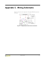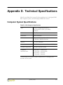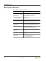
1
SprayVIEW NSx User’s Guide
Image Therm Engineering
142 North Road
Sudbury, MA 01776
(USA)
Part Number: 000261-05
January 2003
SprayVIEW ® is a registered trademark of Image Therm Engineering, Inc.
Microsoft® is a registered trademark of Microsoft Corp.
Windows NT and Windows 2000 are trademarks of Microsoft Corp.
LabVIEW® Copyright 2001 National Instruments Corporation.
All Rights Reserved. United States Patent Nos. 4,901,221; 4,914,568; 5,291,587;
5,301,366; and 5,475,951. Other patents pending.
All other products and company names are the property of their respective
owners.
Copyright 1998, 1999, 2002, 2003 Image Therm Engineering, Inc.
All rights reserved.
Notice
Image Therm Engineering believes the information in its user manuals to be
accurate as of the date of publication. In the event of technical or typographical
errors, Image Therm Engineering may revise its user manuals without notice.
Please consult Image Therm Engineering if you suspect a user manual contains
serious errors.
Image Therm Engineering’s user manuals may not be reproduced or transmitted
in any form, electronic or mechanical, including photocopying, recording,
storing in an information retrieval system, or translating, in whole or in part,
without the prior written consent of Image Therm Engineering, Inc.
The SprayVIEW NSx Automated Nasal Spray Pump Actuation System and all
related developments thereto, including the mechanical and software design and
implementation thereof, are patent pending.
Use of the Image Therm Engineering SprayVIEW NSx Automated Nasal Spray
Pump Actuation System (the “SprayVIEW NSx System”) is subject to the terms
and conditions, including without limitation those with respect to restrictions of
use, limited warranties, and limitations of liability, set forth in the SprayVIEW
NSx License Agreement.
Image Therm Engineering wants to receive your comments on our products and
manuals. We are interested in the applications you use with our products, and we
want to help you if you have problems with them. Feel free to contact us:
Corporate Headquarters
ii
Tel:
(978) 371-8822 Monday through Friday, 8:00 AM – 5:00 PM EST
Fax:
(978) 371-8942
E-mail:
[email protected]
Internet:
www.imagetherm.com
January 2003
Contents
Preface ............................................................................................................................................................. ix
Structure of This Manual ........................................................................................................................................ ix
Document Conventions ........................................................................................................................................... x
Notes, Cautions, and Warnings .............................................................................................................................. x
Related Documentation ........................................................................................................................................... x
Chapter 1 Overview
Chapter 2 Calibration and Self-Tests
Hardware Test..........................................................................................................................................................2-1
Calibration ................................................................................................................................................................2-3
Load Cell Calibration.......................................................................................................................................2-5
Safety Collar ......................................................................................................................................................2-9
Position Measurement Verification ................................................................................................................... 2-14
Chapter 3 Operation
Device Setup ............................................................................................................................................................3-1
Insert the Device..............................................................................................................................................3-2
Characterize the Device ..................................................................................................................................3-5
Profile Design ....................................................................................................................................................... 3-13
How To Design a Profile ............................................................................................................................. 3-16
Save and Load a Profile................................................................................................................................ 3-17
Invalid Profiles............................................................................................................................................... 3-18
Actuation ............................................................................................................................................................... 3-19
Triggering Options........................................................................................................................................ 3-20
Output Options............................................................................................................................................. 3-20
Conduct an Experiment............................................................................................................................... 3-21
External Triggering ....................................................................................................................................... 3-22
Operating Limits ........................................................................................................................................... 3-22
Force and Distance Data.............................................................................................................................. 3-23
Experiment Information..................................................................................................................................... 3-24
Test Reports .......................................................................................................................................................... 3-28
Chapter 4 Troubleshooting
January 2003
iii
Appendix A
SprayVIEW NSx Theory
Appendix B
Glossary
Appendix C
Wiring Schematic
Appendix D
Technical Specifications
Computer System Specifications......................................................................................................................... D-1
Physical Specifications .......................................................................................................................................... D-2
Appendix E
Certifications
Declaration of Conformity ...................................................................................................................................E-1
Electromagnetic Compatibility......................................................................................................................E-2
Low Voltage Safety..........................................................................................................................................E-3
Machinery Safety .............................................................................................................................................E-3
CE Certification......................................................................................................................................................E-3
Authorization ..........................................................................................................................................................E-3
When and Where Issued ................................................................................................................................E-3
Signature ...........................................................................................................................................................E-3
iv
January 2003
Figures
Figure 1.1
Figure 2.1
Figure 2.2
Figure 2.3
Figure 2.5
Figure 2.6
Figure 2.7
Figure 2.8
Figure 2.9
Figure 2.10
Figure 2.11
Figure 2.12
Figure 2.13
Figure 2.14
Figure 2.15
Figure 2.16
Figure 2.17
Figure 2.18
Figure 2.19
Figure 2.20
Figure 2.21
Figure 3.1
Figure 3.2
Figure 3.3
Figure 3.4
Figure 3.5
Figure 3.6
Figure 3.7
Figure 3.8
Figure 3.9
Figure 3.10
Figure 3.11
Figure 3.12
Figure 3.13
Figure 3.14
SprayVIEW NSx Actuator...................................................................................................... 1-1
Hardware Test........................................................................................................................... 2-1
Power Loss – Re-establish Home Position .......................................................................... 2-2
SprayVIEW NSx Actuator with Calibration Masses........................................................... 2-3
Calibration Setup ...................................................................................................................... 2-5
Calibration Step 1: Pedestal Only........................................................................................... 2-6
Calibration Step 2: 1 Kg Mass ................................................................................................ 2-6
Calibration Step 3: 3 Kg Mass ................................................................................................ 2-7
Calibration Results.................................................................................................................... 2-8
Calibration Completion ........................................................................................................... 2-8
Go to the Top Position to Remove Collar........................................................................... 2-9
Remove the Collar.................................................................................................................. 2-10
Remove the Collar from the Rear Post of the Actuator................................................... 2-10
Go to the Base ........................................................................................................................ 2-11
Go to the Top Position to Insert the Collar....................................................................... 2-12
Insert the Collar ...................................................................................................................... 2-12
Secure the Collar to the Rear Post of the Actuator........................................................... 2-13
Position Measurements Warning ......................................................................................... 2-14
Position Measurements Testing ........................................................................................... 2-14
Position Measurements – Verification Passed ................................................................... 2-15
Position Measurements – Verification Failed .................................................................... 2-15
Device Setup.............................................................................................................................. 3-2
Assemble the Pump and the Pump Clamp........................................................................... 3-3
Insert the Assembled Clamp and Pump in the Actuator ................................................... 3-4
Home Position .......................................................................................................................... 3-5
Contact Position ....................................................................................................................... 3-6
End of Stroke Position ............................................................................................................ 3-7
Abort Operation ....................................................................................................................... 3-8
Pump Characterization Data (Automatic Mode)................................................................. 3-9
Warning for Manual Mode.................................................................................................... 3-10
Device Setup Ready to Characterize in Manual Mode ..................................................... 3-11
Pump Characterization in Manual Mode ............................................................................ 3-12
Default Profile in Profile Design.......................................................................................... 3-13
Nine Parts of an Actuation Profile ...................................................................................... 3-15
Profile Design – Default Profile........................................................................................... 3-16
January 2003
v
Figure 3.15
Figure 3.16
Figure 3.17
Figure 3.18
Figure 3.19
Figure 3.20
Figure 3.21
Figure 3.22
Figure 3.23
Figure 3.24
Figure 3.25
Figure C.1
Invalid Profile Error Message............................................................................................... 3-18
Actuation.................................................................................................................................. 3-19
Actuation Progress Dialog Box............................................................................................ 3-21
Actuator Outside of Operating Limits ................................................................................ 3-22
VCR Controls to View Force and Distance Data ............................................................. 3-23
Experiment Information ....................................................................................................... 3-24
Experiment Information with Required Fields Filled....................................................... 3-27
Post-Test Options .................................................................................................................. 3-27
HTML Report Generated from SprayVIEW NSx............................................................ 3-28
Experiment Path in Windows Explorer.............................................................................. 3-29
Text Report Generated from SprayVIEW NSx ................................................................ 3-29
SprayVIEW NSx Interconnection Schematic ......................................................................C-1
January 2003
vi
Tables
Table 3.1
Table 3.2
Table 3.3
Table 3.4
Table 3.5
Table 3.6
Table 4.1
Table D.1
Table D.2
Table E.1
Default Settings in Profile Design ........................................................................................... 3-14
Actuation Statistics in Profile Design ..................................................................................... 3-14
Nine Phases of an Actuation Stroke ....................................................................................... 3-15
Triggering Options ..................................................................................................................... 3-20
Output Options .......................................................................................................................... 3-20
Required Fields in Experiment Information ......................................................................... 3-25
Troubleshooting ............................................................................................................................4-1
NSx Computer Specifications .................................................................................................. D-1
NSx Physical Specifications ...................................................................................................... D-2
Applicable Standards ..................................................................................................................E-2
January 2003
vii
viii
January 2003
Preface
This manual describes the use of the SprayVIEW® NSx standalone
system to test and evaluate the performance of mechanical nasal spray
pumps commonly used in the pharmaceutical industry.
Structure of This Manual
This manual consists of four chapters and five appendices:
Chapter 1, Overview
Introduces you to the purpose and use of the
SprayVIEW NSx standalone system.
Chapter 2, Calibration and Self-Tests
Explains how to calibrate the load cell in the NSx
actuator, and explains the hardware self-tests the
actuator conducts.
Chapter 3, Operation
Explains how to characterize a nasal spray pump,
design an actuation profile, conduct a test, and store
test data.
Chapter 4, Troubleshooting
Describes some common issues that develop during
NSx use and how to resolve them.
Appendix A, SprayVIEW NSx Theory
Gives a brief background on NSx theory and the
purpose for automated testing of nasal spray pumps.
Appendix B, Glossary
Defines some terminology common to NSx
operation.
Appendix C, Wiring Schematic
Shows how the components of the SprayVIEW NSx
system are connected.
Appendix D, Technical Specifications
Lists the environmental, physical and operating
specifications for the unit.
Appendix E, Certifications
Gives the conformity and compliance statements for
the manual and the NSx standalone equipment.
January 2003
ix
Document Conventions
The text in clickable buttons is in ARIAL BOLD SMALL CAPS.
Labels in the user interface appear in Optima italics.
Notes, Cautions, and Warnings
Note, Caution, and Warning icons denote information of special
interest. The icons appear in the column to the left of the text and are
reproduced below with explanations of their meanings. Failure to
observe a Caution or Warning could cause a dangerous condition.
W ARNING
The WARNING icon points to a potentially hazardous situation that, if not
avoided, can result in serious injury.
CAUTION
The CAUTION icon denotes a situation that can result in loss of data or
damage to the instrument.
NOTE
The NOTE icon signifies an operating tip or maintenance suggestion.
Related Documentation
For additional information about SprayVIEW NSx installation and
operation, please refer to the SprayVIEW NSx Installation and
Operational Qualification.
x
January 2003
1. Overview
The SprayVIEW NSx automatically actuates nasal spray pumps in order
to evaluate their performance. Appendix A, SprayVIEW NSx Theory, explains
why automatic actuation improves the reliability of data gathered during the
testing of nasal spray pumps. The NSx system incorporates these
components:
• Actuator
• Computer and monitor
• Keyboard and mouse
• Calibration (weights) masses
• Software CD
• Safety collar and installation tool
• Power supply, cables and connectors
Figure 1.1 illustrates key parts of the SprayVIEW NSx actuator: the triangular
compression plate, the pedestal, and the motor housing. To see a drawing of
the entire SprayVIEW NSx system, see Figure C.1 on page C-1 in Appendix
C, Wiring Schematic.
Figure 1.1 SprayVIEW NSx Actuator
January 2003
1-1
The SprayVIEW NSx software:
Image Therm Engineering sets up and tests the entire SprayVIEW NSx
system at your site. Before you use it, however, check these items:
• Place the actuator on a solid table or other surface capable of
supporting the SprayVIEW NSx system with minimal vibration.
• Perform a visual inspection of the unit to ensure that all electrical
connections are made, and that all mechanical components are
clean, secure and operating properly.
• Inspect the triangular compression plate and ensure that it is free
of any obstacles that may interfere with its movement or
operation.
• Turn on the computer and start the SprayVIEW NSx software.
• Ensure that the load cell calibration is current relative to your
company’s standard instrument calibration interval. Check the
Calibration date in the Hardware Test window.
1-2
January 2003
2. Calibration and Self-Tests
The SprayVIEW NSx software includes self-tests to diagnose problems
and a wizard to calibrate the instrument. This chapter explains the
self-tests and the calibration process. It contains these sections:
• Hardware Test on page 2-1
• Calibration on page 2-3
• Position Measurement Verification on page 2-14
Hardware Test
Hardware Test is the first window that opens when you launch the
SprayVIEW NSx software (Figure 2.1).
Figure 2.1 Hardware Test
January 2003
2-1
Hardware Test
The first three indicators in Hardware Test show the status of these
components:
• Data acquisition board
• Load cell
• Actuator motor
If the indicator for any of these components is red, refer to Chapter 4,
Troubleshooting.
The fourth status indicator in Hardware Test shows whether or not you
must calibrate the load cell in the actuator. The load cell must be
calibrated at least every 30 days.
NOTE
To proceed to any of the windows available from Hardware Test, all four
status indicators must be green.
If the actuator has lost power since you last used it, the dialog box in
Figure 2.2 appears. Click PROCEED to re-establish the triangular compression
plate’s home position.
Figure 2.2 Power Loss – Re-establish Home Position
2-2
January 2003
SprayVIEW NSx User’s Guide
Calibration
If the Calibration indicator in Hardware Test is red, you must calibrate
the load cell underneath the pedestal in order to collect valid data. Click
CALIBRATE LOAD CELL in Hardware Test to launch the calibration wizard.
Figure 2.3 shows the SprayVIEW NSx actuator and the masses needed to
calibrate the load cell.
Pedestal
Triangular
Compression Plate
Figure 2.3 SprayVIEW NSx Actuator with Calibration Masses
The SprayVIEW NSx actuator uses a wizard to guide you through the
calibration process.Figure 2.4 on page 2-4 shows the sequence of steps in the
wizard.
January 2003
2-3
Calibration
Load Cell Calibration
1
2
Safety Collar Removal
5
3
6
7
4
10
Safety Collar Insertion
8
11
12
9
Figure 2.4 Steps in the Calibration Wizard
2-4
January 2003
SprayVIEW NSx User’s Guide
Load Cell Calibration
Calibrate the actuator’s load cell every 30 days or according to company
policy. The procedure in this section focuses only on the calibration
process. It assumes the actuator does not have a safety collar installed.
Refer to Safety Collar on page 2-9 for instructions about how to install and
reinsert the safety collar.
Check the status indicators in Hardware Test to make sure the actuator
has passed its hardware self-tests. If the actuator has failed one or more
self-tests, the CALIBRATE LOAD CELL button is not available. Refer to
Chapter 4, Troubleshooting to resolve a hardware problem.
CAUTION
Do not adjust the pedestal tightness. Tightening or loosening the
pedestal invalidates the load cell calibration and may cause erroneous
measurements.
To calibrate the load cell:
1. Click CALIBRATE LOAD CELL in Hardware Test.
The Setup window appears (Figure 2.5).
Figure 2.5 Calibration Setup
January 2003
2-5
Calibration
2. Click NEXT.
Step 1: Pedestal only opens (Figure 2.6). Follow the instructions that
appear on the left side of the window.
Figure 2.6 Calibration Step 1: Pedestal Only
3. When the green light indicates a valid measurement, click NEXT.
Step 2: 1kg mass opens (Figure 2.7).
Figure 2.7 Calibration Step 2: 1 Kg Mass
2-6
January 2003
SprayVIEW NSx User’s Guide
4. Place the 1 kg mass in the center of the pedestal.
5. When the green light indicates a valid measurement, click NEXT.
Step 3: 3kg mass opens (Figure 2.8).
Figure 2.8 Calibration Step 3: 3 Kg Mass
6. Remove the 1 kg mass and place the 3 kg mass on the center of the
pedestal.
NOTE
Center the 3 kg mass on the pedestal so it does not touch the post
behind the triangular compression plate. Note that the 3 kg mass does
not fit on the pedestal if the safety collar is installed. To remove the
safety collar for calibration, see Safety Collar on page 2-9.
7. When the green light indicates a valid measurement, click NEXT.
January 2003
2-7
Calibration
8. Remove the 3 kg Mass.
The Results window opens (Figure 2.9). The Results window shows
calibration statistics, and a graph compares the measured force at three
points with the theoretical force (shown as a red line).
Figure 2.9 Calibration Results
9. Click NEXT.
The Completion window opens (Figure 2.10).
Figure 2.10 Calibration Completion
10. Click FINISH to exit the calibration wizard.
2-8
January 2003
SprayVIEW NSx User’s Guide
Safety Collar
The safety collar prevents the triangular compression plate from crushing
objects underneath it when it moves to the home position. When the safety
collar is installed, the clearance between the pedestal and the top of the
actuator is not high enough for the 3 kg mass. To place the 3 kg mass on the
pedestal, you must remove the safety collar. The instructions below explain
how to remove the safety collar at the beginning of the calibration process,
and how to reinstall the collar at the end of the procedure.
Begin the calibration process as before:
1. Click CALIBRATE LOAD CELL.
The Setup window opens (Figure 2.5 on page 2-5).
2. Click REMOVE COLLAR in the Setup window.
Go to the top position appears (Figure 2.11).
Figure 2.11 Go to the Top Position to Remove Collar
January 2003
2-9
Calibration
3. Click NEXT.
The triangular compression plate travels to the top position. Remove
the collar appears (Figure 2.12).
Figure 2.12 Remove the Collar
4. Use the tool supplied with the SprayVIEW NSx actuator to remove
the collar from the rear post of the actuator (Figure 2.13).
Figure 2.13 Remove the Collar from the Rear Post of the Actuator
2-10
January 2003
SprayVIEW NSx User’s Guide
5. Click NEXT.
Go to the base opens (Figure 2.14).
Figure 2.14 Go to the Base
6. Click FINISH.
The safety collar wizard closes and Step 1: Pedestal only opens
(Figure 2.6 on page 2-6). Follow the instructions in the calibration wizard
to perform:
•
•
•
Step 1: Pedestal only
Step 2: 1 kg mass
Step 3: 3 kg mass
When all three steps are complete, the Results window opens
(Figure 2.9 on page 2-8).
7. Click NEXT.
The Completion window opens (Figure 2.10 on page 2-8).
January 2003
2-11
Calibration
8. Click INSERT COLLAR.
Go to the top position opens (Figure 2.15).
Figure 2.15 Go to the Top Position to Insert the Collar
9. Check that nothing blocks movement of the triangular compression
plate and click NEXT.
The triangular compression plate travels to the top position and
Insert the collar opens (Figure 2.16).
Figure 2.16 Insert the Collar
2-12
January 2003
SprayVIEW NSx User’s Guide
10. Use the tool supplied with the SprayVIEW NSx actuator to secure
the safety collar to the rear post of the actuator. (Figure 2.17).
Figure 2.17 Secure the Collar to the Rear Post of the Actuator
11. Click NEXT.
Go to the base opens.
12. Click FINISH.
The triangular compression plate travels to the base and the
Completion window opens (Figure 2.10 on page 2-8).
13. Click FINISH to exit the calibration wizard.
January 2003
2-13
Position Measurement Verification
Position Measurement Verification
The last self-test verifies the actuator’s position measurements. To gather
accurate data, the actuator and the SprayVIEW NSx software must be
able to measure the distance between the triangular compression plate
and the actuator’s base. The instructions below explain how to conduct
this test.
1. Click VERIFY POSITION MEASUREMENTS in Hardware Test.
A Warning dialog box appears (Figure 2.18).
Figure 2.18 Position Measurements Warning
2. Remove obstructions as instructed and click NEXT.
The Testing... dialog box appears (Figure 2.19).
Target
Distance
Distance
Travelled
Figure 2.19 Position Measurements Testing
2-14
January 2003
SprayVIEW NSx User’s Guide
•
Figure 2.20 shows the Results window when the actuator passes the
test. Click FINISH to close the Results window and return to Hardware
Test.
Figure 2.20 Position Measurements – Verification Passed
•
Figure 2.21 shows the Results window when the actuator fails the
test. Click FINISH to close the window and return to Hardware Test.
Figure 2.21 Position Measurements – Verification Failed
Click VERIFY POSITION MEASUREMENTS in Hardware Test to run the test a
second time. If the actuator fails the test again, leave the Results window
open and call Image Therm Engineering.
If the actuator passes its hardware tests and the load cell is calibrated, it is
ready to test nasal spray pumps. Click NEXT in Hardware Test to open
Device Setup.
January 2003
2-15
2-16
January 2003
3. Operation
The SprayVIEW NSx actuator uses a Windows-based wizard helps you
prepare for and conduct a test:
• Characterize the device under test (see Device Setup below).
• Design an actuation profile for the test (see Profile Design on
page 3-13).
• Conduct the test itself (see Actuation on page 3-19).
• Save test data and document the test (see Experiment Information on
page 3-24).
During the course of an experiment, the SprayVIEW NSx software:
• Controls the movements of the triangular compression plate.
• Measures the distance of the triangular compression plate from
the actuator base.
• Measures the force that the pedestal exerts on the bottom of the
nasal spray bottle.
Device Setup
To operate the SprayVIEW NSx actuator, first insert the nasal spray
pump in the actuator. Then characterize the device to enable the control
software to take accurate measurements.
Figure 3.1 on page 3-2 shows Device Setup when it opens.
January 2003
3-1
Device Setup
Click the Detection
indicator light to select
Automatic or Manual mode.
Figure 3.1 Device Setup
Insert the Device
A clamp holds the nasal spray pump in place during testing. To assemble
the clamp and to insert the nasal spray pump in the actuator:
1. Click GO TO HOME in Device Setup to return the pedestal to its home
position.
2. Assemble the nasal spray pump and the components of the pump
clamp as shown in Figure 3.2.
a. Select a rubber insert that fits loosely around the pump
nozzle and place it in the top of the Teflon clamp.
b. Insert the pump nozzle into the hole in the bottom of the
Teflon clamp. The flanges of the pump tip should be flush
with the bottom of the Teflon clamp.
c. Place the black screw top over the Teflon clamp and tighten
it until the nozzle is snug.
3-2
January 2003
SprayVIEW NSx User’s Guide
NOTE
To align the screw top with the Teflon clamp, turn the screw top
counter-clockwise until it clicks. Then turn it clockwise to tighten. You
can strip the threads on the screw top if you tighten it too much. Tighten
it only enough to secure the nasal spray pump in the Teflon clamp.
Screw Top
Rubber Insert
Teflon Clamp
Nasal Spray
Pump Flange
Figure 3.2 Assemble the Pump and the Pump Clamp
Now you are ready to insert the spray bottle and clamp into the
actuator.
January 2003
3-3
Device Setup
NOTE
If the pedestal is not positioned as shown in Figure 3.3, click GO TO
HOME in the Device Setup window.
3. Slide the assembled clamp and pump into the slot at the top of the
actuator (Figure 3.3).
Pedestal
Figure 3.3 Insert the Assembled Clamp and Pump in the Actuator
3-4
January 2003
SprayVIEW NSx User’s Guide
Characterize the Device
The actuator must take some simple measurements before it can test the
device. These measurements are based on the following pedestal
positions:
• Home position – The home position is the point of reference for
other measurements. Distance equals zero at the home position
(Figure 3.4).
Home Position
Figure 3.4 Home Position
January 2003
3-5
Device Setup
•
Contact position – The pedestal reaches the contact position
when it just touches the bottom of the spray bottle. The distance
from the home position to the contact position depends on the
size of the spray pump and bottle (Figure 3.5).
Stroke Length
Contact Position
Figure 3.5 Contact Position
Figure 3.5 also shows the stroke length. For purposes of
measurement, the stroke length is the distance the pedestal travels
between the contact position and the end of stroke position
(Figure 3.6 on page 3-7).
3-6
January 2003
SprayVIEW NSx User’s Guide
•
End of stroke position – The top of the actuation stroke is the
farthest distance the pedestal travels from the home position for a
particular device (Figure 3.6).
Bottle at Top of
Actuation Stroke
End of Stroke
Position
Figure 3.6 End of Stroke Position
You can characterize the device in Automatic mode or in Manual mode:
• Automatic mode – The Detection indicator light is green.
SprayVIEW actuates the pump and calculates the stroke length.
• Manual mode – The Detection indicator light flashes red and
yellow. Use Manual mode whenever you need to enter the stroke
length manually.
January 2003
3-7
Device Setup
Automatic Mode
NOTE
Automatic mode determines the contact position and the stroke length
for any nasal spray pump under test. To take these measurements, click
CHARACTERIZE in Device Setup. Observe these operations:
• The pedestal moves to the home position if it is not already
there.
• The pedestal moves upward slowly to find the contact position,
then actuates the pump once.
• The graph in Device Setup plots the force on the pedestal against
the pedestal position over the length of the stroke.
• Measurements for the contact position, the end of stroke
position, and the stroke length appear in the corresponding
indicators to the left of the graph.
To stop the actuator when the pedestal is in motion, click ABORT in the
Abort dialog box (Figure 3.7).
Figure 3.7 Abort Operation
3-8
January 2003
SprayVIEW NSx User’s Guide
After the actuator characterizes a device, the Device Setting graph
displays Force vs. Position data for the stroke just completed. The Stroke
length, End of stroke pos., and Contact pos. fields display the
measurements taken during characterization of the pump. Figure 3.8
illustrates the Device Setup window after characterization is complete.
Contact Position
40.66 mm
End of Stroke Pos.
52.76 mm
Figure 3.8 Pump Characterization Data (Automatic Mode)
January 2003
3-9
Device Setup
Manual Mode
Use Manual mode when you want to enter the stroke length in Device
Setup manually. In Manual mode, Device Setup determines only the
contact position. It does not actuate the pump. To characterize a pump
in Manual mode:
1. Click the Detection indicator light to change to Manual mode.
The dialog box in Figure 3.9 appears.
Figure 3.9 Warning for Manual Mode
CAUTION
3-10
Be careful not to enter a stroke length longer than the actual stroke
length of the pump. If the stroke length is too long, the actuator could
apply excessive force to the pump and may damage it.
January 2003
SprayVIEW NSx User’s Guide
2. Click OK to close the dialog box and proceed.
The Detection indicator light flashes red and yellow. The FIND
button and the data fields below it become active.
Device Setup is ready to characterize the device in Manual mode
(Figure 3.10).
CONTACT POSITION
Figure 3.10 Device Setup Ready to Characterize in Manual Mode
January 2003
3-11
Device Setup
3. Click FIND CONTACT POSITION in Device Setup.
• The pedestal moves to the home position if it is not already
there.
• The pedestal moves upward slowly until it makes contact with
the bottom of the pump.
• The graph in Device Setup plots the force on the pedestal against
the pedestal position (Figure 3.11).
Contact Position
49.35 mm
Figure 3.11 Pump Characterization in Manual Mode
4. Enter the stroke length for the device in Stroke length. To determine
the stroke length:
• Consult the documentation supplied by the pump manufacturer,
or
• Characterize a pump in Automatic mode to measure the pump’s
stroke length.
When you enter the stroke length, the software adds the stroke length to
the contact position and updates the End of stroke pos. indicator.
When characterization of the pump is complete, click NEXT to open
Profile Design.
3-12
January 2003
SprayVIEW NSx User’s Guide
Profile Design
The actuation profile determines the pedestal’s velocity and acceleration
throughout the actuation stroke. In a symmetric profile, velocity and
acceleration during the actuation and the return strokes are equal. To
design a symmetric profile, set these parameters:
• Velocity of the pedestal during the actuation and return strokes
• Acceleration of the pedestal during the actuation and return strokes
• Initial delay
• Hold time
• Final delay
The default profile in Figure 3.12 illustrates a symmetric profile.
Actuation and return
stroke settings for a
symmetric profile
Return stroke
settings for an
asymmetric profile
Figure 3.12 Default Profile in Profile Design
In an asymmetric profile, velocity and acceleration during the actuation
and return strokes are not equal. Set the return stroke velocity and
acceleration ( Velocity rs and Accel. rs) separately from the actuation
stroke velocity and acceleration. The initial delay, hold time, and final
delay are also adjustable in an asymmetric profile.
January 2003
3-13
Profile Design
Table 3.1 lists the default settings for the profile that appears when you first
open Profile Design.
Table 3.1 Default Settings in Profile Design
Parameter Label
Setting Description
Velocity [mm/s]
30.00
Maximum velocity during the actuation stroke
Accel. [mm/s^2]
500
Acceleration during the actuation stroke
Velocity rs [mm/s]
30.00
Maximum velocity during the return stroke
Accel. rs [mm/s^2]
200
Acceleration during the return stroke
Initial delay [ms]
100
Delay before the actuation stroke begins
Hold time [ms]
50
Time the pedestal remains still at the top of the actuation stroke
Final delay [ms]
100
Delay after the return stroke ends
NOTE
As you adjust the default settings for your experiment, consult with the
pump manufacturer, or use trial and error to determine the values most
appropriate for your pump.
Statistics for both the actuation stroke and the return stroke appear
below the parameter settings. Table 3.2 defines these statistics.
Table 3.2 Actuation Statistics in Profile Design
Statistic Label
Description
D accelerating (mm)
Distance required to reach maximum velocity
D at maxV (mm)
Distance traveled at maximum velocity
D decelerating (mm) Distance required to decelerate from maximum velocity
T accelerating (ms)
Time required to reach maximum velocity
T at maxV (ms)
Time spent at maximum velocity
T decelerating (ms)
Time required to decelerate from maximum velocity
T top (ms)
Time required to reach the top of the stroke
T total (ms)
Total time required for the entire actuation, including the initial delay,
actuation, hold time, return time, and final delay
3-14
January 2003
SprayVIEW NSx User’s Guide
Figure 3.13 shows the nine phases of an actuation stroke.
1
2
3
4 5
6
7
8
9
Figure 3.13 Nine Parts of an Actuation Profile
Table 3.3 describes the nine phases shown in Figure 3.13.
Table 3.3 Nine Phases of an Actuation Stroke
Phase
Description
Phase 1
Initial delay
Phase 2
Accelerating to maximum velocity on the actuation stroke
Phase 3
Moving at maximum velocity (actuation stroke)
Phase 4
Decelerating to zero (actuation stroke)
Phase 5
Hold time
Phase 6
Accelerating to maximum velocity (return stroke)
Phase 7
Moving at maximum velocity (return stroke)
Phase 8
Decelerating to zero (return stroke)
Phase 9
Final delay
January 2003
3-15
Profile Design
How To Design a Profile
The profile in the Profile Design graph updates automatically as you
adjust the parameters to the left of the graph. Follow these steps as you
modify the default profile in Figure 3.14.
Figure 3.14 Profile Design – Default Profile
1. Click the check box under Symmetric to design a symmetric profile,
or clear the check box to design an asymmetric profile.
2. Adjust the Velocity setting for the actuation stroke.
Use the up and down arrows, or type the new value directly in the
data field. If the profile is asymmetrical, adjust the return stroke
velocity (Velocity rs) as well.
3. Adjust the Accel. setting for the actuation stroke.
Use the up and down arrows, or type the new value directly in the
data field. If the profile is asymmetrical, adjust the return stroke
acceleration ( Accel. rs) as well.
4. Adjust the settings for the Initial delay, Hold time, and Final delay.
Use the up and down arrows, or type the new value directly in the
data field.
3-16
January 2003
SprayVIEW NSx User’s Guide
Save and Load a Profile
Whenever you design a profile, you can save it for future use.
To save a profile:
1. Click SAVE PROFILE under the Actuation Statistics in Profile Design
(Figure 3.14).
A Save As dialog box appears.
2.
3.
4.
To
1.
Select the profiles folder, D:\SprayVIEW\Profiles.
Enter a file name.
Click SAVE to save the file and close the dialog box.
load a previously saved profile:
Click LOAD PROFILE under the Actuation Statistics in Profile Design
(Figure 3.14).
An Open dialog box appears.
2. Navigate to the profiles folder, D:\SprayVIEW\Profiles.
3. Select the desired profile name and click OPEN.
Data from the saved profile populates the fields in Profile Design.
January 2003
3-17
Profile Design
Invalid Profiles
During a typical actuation stroke, the pedestal accelerates, travels at
constant velocity, then decelerates to a stop. If the distance required to
accelerate and decelerate is greater than the stroke length, the software
flags the profile as invalid. In an invalid profile, the actuator cannot
reach the designated velocity.
Figure 3.15 shows the error message that appears in the Profile Design graph
when you enter velocity and acceleration settings that make the profile
invalid. To create a valid profile, follow the instructions in the error message.
Increase the acceleration or decrease the velocity in the fields to the left of
the Profile Design graph.
Figure 3.15 Invalid Profile Error Message
After you save the profile, click NEXT in Profile Design to open
Actuation.
3-18
January 2003
SprayVIEW NSx User’s Guide
Actuation
Accomplish these tasks from the Actuation window (Figure 3.16):
• Select a triggering option.
• Select an output option.
• Conduct an experiment.
• Trigger the actuator externally.
• Drive an external device.
• View force and distance data for each actuation repetition.
Figure 3.16 Actuation
Use the Actuation step to set these parameters and options:
• Repetitions – Enter the number of repetitions the actuator
completes.
• Delay (s) – Enter the delay between repetitions in seconds. This
setting is available only if the Repetitions setting is greater than
one.
• Triggering option – Select whether the software or an external
device triggers the actuator.
• Output option – Select whether the actuator sends a digital pulse
to a synchronized device or not.
January 2003
3-19
Actuation
Triggering Options
Operation of the actuator depends on the triggering option you select.
Table 3.4 lists the three triggering options available. Select the second or
third option to use a manual trigger or some other device to trigger the
actuator.
Table 3.4 Triggering Options
Option Label
Description
Software triggering The software initiates all repetitions automatically
when you click ACTUATE.
Trigger the first
actuation only
The label in the ACTUATE button changes to ARM.
Use an external triggering device to initiate all of
the requested repetitions.
Trigger each
actuation
The label in the ACTUATE button changes to ARM.
Use an external triggering device to initiate each
actuation.
Output Options
Some tests require that other equipment be synchronized with the
actuator. Select one of the TTL output options to synchronize operation of
an external device with the operation of the SprayVIEW NSx actuator
(Table 3.5).
Table 3.5 Output Options
Option Label
Description
No TTL output
No digital output is sent.
TTL output on
The actuator sends a single digital signal when you
first actuation only trigger the first actuation. Subsequent actuations, if
any, do not initiate a digital signal.
TTL output on
each actuation
3-20
The actuator sends a digital signal for each
actuation you trigger.
January 2003
SprayVIEW NSx User’s Guide
Conduct an Experiment
To set actuation parameters and options when you plan to use software
triggering and a synchronized external device:
1. Enter the number of Repetitions to perform during the test.
2. Enter the Delay in seconds between each repetition.
3. Use the up and down arrows to select Software triggering, if it is not
already selected.
4. Use the up and down arrows to select TTL output on each actuation.
5. Click ACTUATE.
These events follow:
•
•
•
•
The Actuation Progress dialog box appears (Figure 3.17).
The actuator performs the requested number of repetitions.
The actuator sends a digital pulse for each repetition.
The graph displays force and distance data for each actuation.
Figure 3.17 Actuation Progress Dialog Box
NOTE
Click ABORT OPERATION in the Actuation Progress dialog box to interrupt
the test and stop the actuator. When you abort a test, the system does
not record data for the repetitions the actuator has completed.
January 2003
3-21
Actuation
External Triggering
You must arm the actuator before you operate it when you use an
external triggering device. If you selected Trigger the first actuation only or
Trigger each actuation, follow these steps:
1. Click ARM.
The Actuation Progress dialog box appears (Figure 3.17 on page 3-21).
The equipment is armed and you can use an external device to operate
the actuator.
2. Use an external device to trigger the first actuation.
• The progress bar in the dialog box advances and the rest of the
repetitions follow if you selected Trigger the first repetition only.
• The progress bar in the dialog box advances and stops if you
selected Trigger each actuation. Use the external triggering device
to initiate each repetition.
The dialog box closes automatically when the repetitions are
complete.
Operating Limits
The SprayVIEW NSx actuator has built-in safety procedures and settings
intended to prevent application of excessive force to the pump or the
motor. If such a condition arises during actuation, the motor stops
moving, the actuation is aborted and the error message in Figure 3.18
appears.
Figure 3.18 Actuator Outside of Operating Limits
The message indicates that the SprayVIEW NSx motor cannot operate safely.
To clear the error:
1. Click CHANGE SETTINGS in the dialog box.
SprayVIEW returns you to Profile Design, where you can modify
the acceleration and velocity settings.
2. Change the velocity and acceleration settings in Profile Design.
3-22
January 2003
SprayVIEW NSx User’s Guide
3. Click NEXT in Profile Design.
The Actuation step reappears.
4. Operate the actuator with the new settings.
If the new settings do not resolve the problem, check the actuator to make
sure:
• Nothing blocks movement of the triangular compression plate.
• The nasal spray pump is not stuck in its current position.
Force and Distance Data
Go
to
be
gi
Ba
ckw nning
ard
Ste
s
pB
ack
Re
ver
se
Pa
use
Pla
y
Ste
pF
orw
Fa
st F ard
orw
Go
ard
to
En
d
When you execute multiple repetitions, the Actuation graph plots force and
distance against time for each actuation. The data fields in the lower left-hand
portion of the Actuation window display these values:
• Max. force – The maximum force exerted on the pedestal during the
actuation stroke.
• Max. force location – Distance the pedestal has traveled from the
contact position at the time the maximum force is exerted.
Use the VCR controls underneath the graph to view force and distance data
for each actuation (Figure 3.19).
Figure 3.19 VCR Controls to View Force and Distance Data
Click NEXT to open Experiment Information.
January 2003
3-23
Experiment Information
Experiment Information
Use the Experiment Information step to document the test and to save test
data (Figure 3.20).
The software
uses these
required entries
to construct the
Experiment Path.
The Base Path
plus the required
entries compose
the Experiment Path.
Click here to select
the Base Path.
These characters
make a required
entry invalid.
Figure 3.20 Experiment Information
The required fields in Experiment Information are designated with a red
asterisk. The field name turns from red to black when you fill the field with a
valid entry. The software cannot construct a valid Experiment Path if a
required entry contains a space or one of the other characters listed at the
bottom of the window. You must fill each required field with a valid entry
before you can save experimental data.
NOTE
3-24
When you use the SprayVIEW NSx actuator as a standalone unit, do not
check Used with SprayVIEW NSP.
January 2003
SprayVIEW NSx User’s Guide
Table 3.6 lists the required fields in Experiment Information. The software
constructs an Experiment Path from the entries in these fields. The data for
each actuation must have a unique path and filename, so you cannot
overwrite a data file accidentally.
Table 3.6 Required Fields in Experiment Information
Field Label
Description
Manufacturer
Manufacturer of the product tested.
Drug name
Name of the drug tested.
Lot / Device ID
Identification data for the nasal spray pump.
Experiment type
The type of experiment conducted.
Actuation #
The number of the dose for the current
experiment. Refer to your laboratory records for
this information. For example, if you have actuated
a pump 9 times in previous experiments, the
actuation number is 10.
Actuation Rating
The rated number of actuations for a particular
pump. Refer to the manufacturer’s documentation.
Base Path
The folder on the local drive used to build the
Experiment Path. The default Base Path is
D:\SprayVIEW\Data.
January 2003
3-25
Experiment Information
Complete the required entries in Experiment Information and save the
test data as follows:
1. Enter data in these required fields to construct an Experiment Path:
• Manufacturer
• Drug name
• Lot / Device ID
• Experiment type
• Actuation #
• Actuation Rating
Do not duplicate the Experiment Path used for a previous experiment.
2. Click the folder icon in the Base Path field.
A Save As dialog box appears.
3. Navigate to the desired directory and click SELECT CUR DIR.
The selected directory appears in Base Path.
4. Use Custom 1, Custom 2, Custom 3, and Custom 4 to create custom
data entries as needed. Type additional remarks in the Comments
field.
5. Click SAVE DATA.
The Data saved? indicator light changes from red to green, and the
SAVE DATA button becomes unavailable.
The SAVE DATA button becomes available when two conditions hold:
•
•
The Base Path and the required fields all contain valid entries.
The entries make up a unique Experiment Path, so as not to
overwrite previously saved data.
Figure 3.21 shows Experiment Information with all data entered properly
and the SAVE DATA button available. Click SAVE DATA to save an HTML
report and a text report to the directory designated in Experiment Path.
3-26
January 2003
SprayVIEW NSx User’s Guide
Figure 3.21 Experiment Information with Required Fields Filled
Click FINISH in Experiment Information to finish the current test. The dialog
box in Figure 3.22 appears. Click one of the first three options to continue
testing or click the fourth option to QUIT THE PROGRAM.
Return to
Device Setup
to characterize
a new pump.
Return to Profile Design
to modify the actuation profile.
Return to Actuation
to retest the pump.
Opens a dialog box
to prompt you to return the
pedestal to its home position
before the program closes.
Figure 3.22 Post-Test Options
January 2003
3-27
Test Reports
Test Reports
Test data are saved in two separate folders as HTML and as tab-delimited
text. Figure 3.23 shows a sample HTML report open in a browser. To open
an HTML report, refer to the Experiment Path and navigate to the correct
folder, then open the NSx-Report.html file.
Figure 3.23 HTML Report Generated from SprayVIEW NSx
NOTE
3-28
The HTML report formats the test data for viewing. To analyze the data
with third party software, open the plain text report.
January 2003
SprayVIEW NSx User’s Guide
Figure 3.24 shows the Experiment Path in Windows Explorer. Both the
HTML report, NSx-Report.html, and the text report, NSx-Report.txt, reside
in D:\SprayVIEW\Data\...\1of100.
Figure 3.24 Experiment Path in Windows Explorer
Figure 3.25 shows a sample text report open in Notepad. To open a plain text
report, refer to the Experiment Path and navigate to the correct folder, then
open the NSx-Report.txt file.
Figure 3.25 Text Report Generated from SprayVIEW NSx
January 2003
3-29
3-30
January 2003
4. Troubleshooting
Table 4.1 describes symptoms and solutions for problems that can occur
during operation of the NSx actuator.
Table 4.1 Troubleshooting
Symptom
Solution
The load cell calibration results fall
outside the valid ranges.
Do the following:
• Rerun calibration.
• If calibration fails again, contact Image Therm
Engineering.
Data acquisition board indicator
remains red.
If the data acquisition board test fails twice, contact Image
Therm Engineering.
Load cell status indicator remains
red.
Make sure that:
• All cables are properly connected.
• The I/O cable is properly connected to the DAQ
board, serial port (COM1), and the actuation system.
• Power supply is turned ON.
Motor status indicator remains red.
Make sure that:
• All cables are properly connected.
• The I/O cable is properly connected to the DAQ
board, serial port (COM1) and the actuation system.
• Power supply is turned ON.
Verify position measurements test
fails and the dialog box with a table
of values appears.
Do the following:
• Check the I/O cable and rerun the test.
• Check around the system for other equipment
generating electrical noise.
• Install a power conditioner on the AC power line.
• If the position measurements test fails again,
leave the dialog box open and contact Image Therm
Engineering.
The pump fails to characterize.
There may be too much noise on the power supply:
• Make sure the calibration is recent. Re-calibrate.
• Install a power conditioner on the AC power line.
The torque limit is reached.
Decrease the velocity and acceleration settings in Profile
Design.
January 2003
4-1
4-2
January 2003
Appendix A. SprayVIEW NSx Theory
Automated testing of nasal spray pumps yields test data that are more
reliable than the data that result from manual methods. That is because
spray patterns depend so heavily on actuation velocity and acceleration.
For example:
• High actuation velocity and acceleration produce smaller
droplets in a more atomized cloud.
• Low actuation velocity and acceleration levels produce larger
droplets in more stream-like sprays.
The FDA requires these measurements in submissions for approval of
drugs delivered by nasal spray pumps:
• Cross-sectional uniformity, or spray pattern.
• Divergence angle, or plume geometry.
• Evolution of the spray pattern over time.
• Particle size distribution.
The FDA recommends that test labs use automated actuation systems to
reduce variability in these measurements due to operator factors.
Automated actuation also increases measurement sensitivity, in order to
detect differences among products.
During product development, analysts can use these measurements to
design a delivery system that accounts for the properties of the fluid that
carries the drug. Automated testing also helps to find acceptable
tolerances for variables of interest during stability testing. Lastly, quality
control of release grade products requires highly consistent test methods
and sensitive measurement technologies.
January 2003
A-1
A-2
January 2003
Appendix B. Glossary
The glossary below defines common NSx terms.
Actuation force
The amount of force the pedestal measures when
actuating the nasal spray pump.
Actuation profile
The velocity, acceleration, and delay times used to define
the actuation and return strokes.
Actuation stroke
The movement of the pedestal from the contact position
to the end of stroke position.
Contact position
The position of the triangular compression plate when
the pedestal first contacts the device.
Distance
The distance the pedestal has travelled from the home
position.
End of stroke position
The position of the triangular compression plate when
the nasal spray pump is fully actuated.
Home position
The pedestal’s position at the bottom of its range.
NIST
National Institute of Standards and Technology.
NSP
Nasal Spray Pump.
Return stroke
The movement of the pedestal from the end of stroke
position to the contact position.
Stroke length
The distance between the contact position and the end
of stroke position.
January 2003
B-1
B-2
January 2003
Appendix C. Wiring Schematic
Figure C.1 shows how the components of the SprayVIEW NSx system are
connected.
Figure C.1 SprayVIEW NSx Interconnection Schematic
January 2003
C-1
C-2
January 2003
Appendix D. Technical Specifications
Table D.1 and Table D.2 on page D-2 list specifications for the SprayVIEW
NSx computer system, and for the SprayVIEW NSx actuator.
Computer System Specifications
Table D.1 NSx Computer Specifications
Type
Factory configured workstation,
Intel Pentium III CPU @ 500 MHz,
minimum
RAM
256 MB, minimum
Hard Drive
20 GB, minimum
OS
Microsoft Windows NT 4.0 Workstation
or Windows 2000 Professional
Monitor
17" color, minimum
Accessories
CD-RW drive, network interface card (NIC)
Installed components
PCI data acquisition board
Usernames
and Passwords*
Username1:
Password:
Username2:
Password:
administrator
sprayviewadm
sprayview
sprayview
* Consult with your network systems administrator for managing user
accounts on the system.
January 2003
D-1
Physical Specifications
Physical Specifications
Table D.2 NSx Physical Specifications
D-2
Dimensions (WxHxD)
146 x 198 x 210 mm (5.8 x 7.8 x 8.3 in)
Weight
3.8 kg (8.5 lb)
Construction
Anodized aluminum, stainless steel
Total Travel Distance
90 mm (3.5 in)
Position Resolution
1.27 micrometer (5.00 microinch), nominal
Velocity Range
1–200 mm/s (0.04–7.87 in/s),
achievable velocity depends on acceleration
Acceleration/
Deceleration
100–100,000 mm/s2 (4–4000 in/s2),achievable
acceleration/deceleration depends on velocity
Resistive Force Range
0–110 Newtons (0–25 lbs),
depends on velocity and acceleration
Force Sensor
Calibration
NIST traceable, precision mass set included
(1 kg, 3 kg)
Electrical Power
100–120 V~ / 200–240 V~ 3.2 A Max.
47–63 Hz
Certifications
CE Compliance, IQ/OQ and
Service/Support Options
January 2003
Appendix E. Certifications
Declaration of Conformity
Manufacturer
Image Therm Engineering, Inc.
Manufacturer’s Address
142 North Road
Sudbury, MA 01776 USA
The manufacturer hereby declares the following:
Product Name
SprayVIEW NSx
Model Numbers
All
Product Options
All
Product Category
The automated NSx actuation system conforms to
the directives, standards and other normative
documents listed below.
January 2003
E-1
Declaration of Conformity
Electromagnetic Compatibility
Council Directive 89/336/EEC, Electromagnetic Compatibility,
EN 61326-1:1997+A1 and the following:
.
Table E.1 Applicable Standards
E-2
Standard Number
Description
EN61000-4-2:1995
Electrostatic Discharge (ESD) Immunity:
4 kV Contact Discharge; 4kV Air Discharge.
EN61000-4-3:1995
Radiated Electromagnetic Field Immunity:
10 V/m, Vertical and Horizontal
Polarization;
80-1000 MHz, 1 kHz, 80% AM; 900 MHz,
200 Hz, 50% PM.
EN61000-4-4:1995
Electrical Fast Transient / Burst Immunity:
1 kV, 5/50 ns, 5 kHz on AC mains; 0.5 kV,
5/50 ns, 5 kHz on I/O lines.
EN61000-4-5:1995
Surge Immunity: 1 kV Common mode;
0.5 kV Differential mode.
EN61000-4-6:1996
Common Mode Conducted Immunity:
3 V, 0.15-80 MHz, 1 kHz 80% AM applied to
AC mains and to LAN.
EN61000-4-8:1993
Radiated Power Frequency Magnetic Field:
No magnetic sensitive components; complies
without testing.
EN61000-4-11:1993
Voltage Interruption: 100% 1 cycle (20 ms).
EN55011:1998
FCC 15.109(g)
FCC 15.107(e)
Radiated and Conducted Emissions: Class A,
Group 1.
EN61000-3-2:1995
Power Harmonic Current: Class A.
EN61000-3-3:1995
Voltage Fluctuation (Flicker): Section 5.
January 2003
SprayVIEW NSx User’s Guide
Low Voltage Safety
Council Directive 73/23/EEC, Low Voltage Safety, EN61010-1:1993+A2.
Machinery Safety
Council Directive 98/37/EC, Machinery Safety, EN61010-1:1993+A2.
CE Certification
The product described in this manual complies with all
applicable European Union (CE) directives. Image Therm
Engineering, Inc. will not retest or re-certify systems or
components that have been reconfigured after sale.
Authorization
Technical documentation required to demonstrate that the above
products meet the requirements of the EMC, Low Voltage Safety, and
Machinery Safety Directives has been compiled by Image Therm
Engineering, Inc. and is available for inspection by the relevant
enforcement authorities.
When and Where Issued
This certification issued May 1, 2002, Sudbury, Massachusetts USA.
Signature
Name: Dino J. Farina
Position: President
January 2003
E-3
E-4
January 2003