1
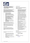
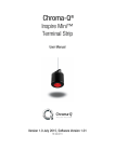
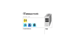
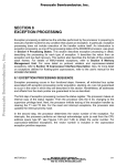
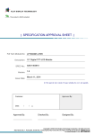
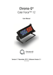
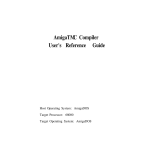
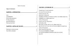
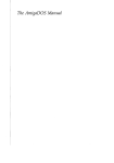
ACCELERATOR CARD
User’s Guide
Copyright © 1989 by Commodore Amiga, Inc. All Rights Reserved. This document may
not, in whole or in part, be copied, photocopied, reproduced, translated, or reduced to any
electronic medium or machine readable form, without prior consent, in writing, from
Commodore-Amiga, Inc.
With this document, Commodore makes no warranties or guarantees, either express or
implied, with respect to the products described, their functionality, compatibility, or availability. Further, Commodore assumes no responsibility or liability for statements or representations made by itself or by third party vendors or in the publications reproduced herein.
IN NO EVENT WILL COMMODORE BE LIABLE FOR DIRECT, INDIRECT, INCIDENTAL,
OR CONSEQUENTIAL DAMAGES RESULTING FROM ANY CLAIM ARISING OUT OF
THE REPRESENTATIONS MADE HEREIN, EVEN IF IT HAS BEEN ADVISED OF THE
POSSIBILITIES OF SUCH DAMAGES. SOME STATES DO NOT ALLOW THE EXCLUSION OR LIMITATION OF SUCH WARRANTIES OR DAMAGES, SO THE. ABOVE EXCLUSIONS OR LIMITATIONS MAY NOT APPLY.
Information in this document is subject to change without notice and does not represent a
commitment on the part of Commodore. Commodore and the Commodore logo are registered trademarks or Commodore Electronics Ltd. Amiga is a registered trademark of
Commodore-Amiga, Inc. Motorola is a registered trademark of Motorola, Inc. UNIX is a
registered trademark of AT&T.
F.C.C. ID
BR98YVA2630
User’s Manual Statement
WARNING: This equipment has been certified to comply with the limits for a Class B
computing device, pursuant to subpart J of Part 15 of the Federal Communications Commissions rules. It also complies with Standard C108.8-M1983 of the Canadian Standards
Association’s regulations. These rules and regulations are designed to provide reasonable
protection against radio and television interference in a residential installation. If not
installed properly, in strict accordance with the manufacturer’s instructions, it may cause
interference. If you suspect interference, you can test this equipment by turning it off and
on. If this equipment does cause interference, correct it by doing any of the following:
• Reorient the receiving antenna or AC plug.
• Change the relative positions of the computer and the receiver.
• Plug the computer into a different outlet so that the computer and receiver are on
different circuits.
CAUTION: Only computers and peripherals with shield-grounded cables (computer inputoutput devices, terminals, printers, etc.), certified to comply with Class B limits, can be
attached to this device. Operation with non-certified equipment may result in communications interference.
Your house AC wall receptacle must be a three-pronged type (AC ground). If not, contact an
electrician to install the proper receptacle. If a multi-connector box is used to connect the
computer and peripherals to AC, the ground must be common to all units.
If necessary, contact your dealer or an experienced radio-television technician for additional
suggestions. You may find the following FCC booklet helpful: “How to Identify and Resolve
Radio-TV Interference Problems.”’ The booklet is available from the U.S. Government
Printing Office, Washington, DC 20402, stock no. 004 000-00345-4.
Table of Contents
1. Introduction. . . . . . . . . . . . . . . . . . . . . . . . . . . . . . . . . . . . . . . . . . . 1
2. How to Install The A2630 Accelerator Card. . . . . . . . . . . . . . . . . . . . 3
Removing the Amiga’s Cover. . . . . . . . . . . . . . . . . . . . . . . . . . . 3
Installing the A2630. . . . . . . . . . . . . . . . . . . . . . . . . . . . . . . . . . 6
3. Operation. . . . . . . . . . . . . . . . . . . . . . . . . . . . . . . . . . . . . . . . . . . . . 9
Compatibility and Testing. . . . . . . . . . . . . . . . . . . . . . . . . . . . . 10
Notes to Software Developers. . . . . . . . . . . . . . . . . . . . . . . . . . 11
Appendix A: Description of the A2630 Board. . . . . . . . . . . . . . . . . . 13
Appendix B: Installing a Faster Math Chip. . . . . . . . . . . . . . . . . . . . 17
Appendix C: Installing An Additional 2 MB of Memory. . . . . . . . . . . 19
Appendix D: Technical Specifications and Schematics. . . . . . . . . . . . 21
1. Introduction
The Amiga computer system was designed so that it can be
easily upgraded for use with other members of the Motorola®
68000 CPU family. By installing the A2630 accelerator card, your
A2000 is upgraded to a 68030 CPU. This 32-bit 68030 CPU vastly
increases processing speed over the 68000 CPU in several important ways:
• It reads and writes data in 32-bit chunks instead of 16 bit.
• Its on-chip cache memory allows faster performance,
even with slower memory systems.
• It eliminates the need for a 68851 Memory Management
Unit because it performs these functions directly on the
chip.
• It can directly use a 68881 or 68882 Floating Point Unit for
very fast math calculations.
The A2630 is a 68030 based accelerator card that plugs into the
coprocessor slot of the Amiga? 2000. The card contains the 68030
CPU and a 68882 Floating Point Unit. The 68030 is clocked at
approximately 25 MHz, nearly four times the clock speed of the
Amiga’s 68000 CPU. The A2630 also contains fast, 32-bit wide
memory to complement the 32-bit Motorola chips. It comes with
2 or 4 megabytes of 32-bit wide on-card RAM which runs at the
68030’s speed. With this fast memory installed, the A2630 may
deliver a 400% - 600% speed increase in most integer based
operations. The card also has 64 K of ROM (expandable to 128K)
which is used for diagnostics, boot-up options, and some initializations used by alternate software configurations (such as the
UNIX® operating system).
1
2. How to Install The A2630
Accelerator Card
WARNING: Unplug the Amiga 2000 before installing the
A2630. Installing the A2630 with the power on could cause
injury to the installer and damage to the equipment. Commodore will not be responsible for any damages caused by improper installation of the A2630. Such improper installation
may void the warranties on both the Amiga 2000 and the A2630.
Before beginning, disconnect the mouse and keyboard from the
front of the Amiga, and remove the power cord and any peripherals attached to the back of the machine.
A Phillips-head screwdriver is needed.
Removing the Amiga’s Cover
On the lower left side of the Amiga, remove the two screws that
hold the metal cover to its base. Remove the two screws on the
lower right side of the Amiga.
Figure 1
Screws on the lower left side of the Amiga
3
Remove the center screw from the rear of the Amiga. Be careful
to remove the correct screw as shown.
Center Screw
Figure 2
Center screw on the rear of the Amiga
Turn the Amiga so that you are facing the front of the machine.
Grasp the cover on both sides, slide it towards you, and lift
upward. If the cover gets stuck, do not force it. Look under the
top of the cover towards the middle. Check to see if any wires or
cables are caught under the small projection where the middle
screw had been attached. If anything is caught, gently untangle
it, and continue to slide the cover off.
4
Figure 3
Cover removal — side view
Before installing the A2630, you must first determine whether
your Amiga 2000 has a 2-layer or 4-layer motherboard. Some
machines assembled in West Germany have 4-layer motherboards which must have the 68000 CPU chip removed before the
A2630 can be installed. To determine the type of board you
have, look at the lower left-hand corner of the motherboard
as you face the machine. If you see a large label which says
COMMODORE AMIGA 2000, the assembly number, and
MADE IN GERMANY (BSW), you have a 4-layer motherboard.
In this case, consult an authorized service center to have your
A2630 installed. If your label is different, you have a 2-layer
motherboard, and you can continue on with the installation.
Figure 4
4 layer board
5
Installing the A2630
The A2630 accelerator card fits into the 86-pin CPU slot next to
the existing 68000 CPU. To locate this slot, turn the Amiga so
that the front of the machine faces you. To your right will be the
disk drive plate and power supply. To your left are a number of
expansion slots. The existing 68000 CPU is underneath the left
edge of the disk drive plate. The 86-pin CPU slot is to the left of
the CPU, as shown in the picture. Locate the rear metal plate
that aligns with the slot. Loosen the screws and remove the
metal plate from the machine.
POWER SUPPLY
86 PIN CPU SLOT
DISK DRIVE
68000 CPU
Figure 5
A2000 — Right side view (looking down)
6
The A2630 slides into this 86-pin slot. Carefully line up the edge
of the card with the plastic groove at the front of the machine.
Slide the card down so it fits into the 86-pin slot. Make sure that
the card slides free of all cables and obstacles at the back of the
machine. Once the card is in the slot, push down on top of the
card until you feel it snap into place. Make sure to apply firm
pressure on top of the card, and use your free hand as a guide.
Also make sure that the back plate of the card fits properly at the
rear of the machine.
A2630 Card
(back side)
Figure 6
A2630 installation (side view)
Fasten the A2630 back plate to the rear of the machine with the
screws provided.
Now that your A2630 has been installed, re-install any removed
equipment or boards, carefully cover the Amiga, fasten the
screws, and reattach your peripherals.
7
3. Operation
Plug in your A2000 and peripherals and turn the power on.
Hold down both mouse buttons. The A2630 will present you
with a screen of boot-up options.
AmigaDOS on 68000
AmigaDOS on 68030
Amiga UX
Release both mouse buttons. Move the cursor to the box next to
your selection and click either mouse button to make the
selection.
If you choose AmigaDOS on 68000, the accelerator card is disabled,
and the system runs off the 68000 CPU. This option is not
applicable for machines with a 4-layer motherboard since the
68000 CPU must be removed in order to install the A2630. If you
choose this option with the 68000 CPU removed, you will experience system failure.
Some software may not run properly on the A2630 accelerator
card. If your system crashes when using this software, reboot
the system as described above, and choose AmigaDOS on 68000
from the menu. Contact the software developer for information
on possible upgrades that will be compatible with the A2630.
If you choose AmigaDOS on 68030, the system runs off the accelerator card’s 68030 CPU. This is the default option when you
power on or reset the Amiga with the A2630 accelerator card
installed.
If you choose Amiga UX, a UNIX operating system is invoked
(provided you have the proper hardware/software installed and
have set a jumper on J304).
9
Compatibility and Testing
As soon as the Amiga is turned on or comes out of reset, the
A2630 takes over from the 68000. The 32-bit on-card memory
will show up as normally auto-configured memory, and it will
always be the first memory to be auto-configured by the operating system.
You may want to run the FastMemFirst program early in the
startup sequence. This will insure that the 32-bit memory on the
A2630 card is the first FAST memory to be used by any application.
The A2630 card, in addition to increasing the speed in a 32-bit
environment, must also access the 16-bit hardware bus system
of the Amiga 2000. The 68030 CPU has a built-in dynamic bus
sizing feature which adjusts memory cycles to any system resource that it addresses. On the A2630 card, logic tells the 68030
chip that its on-board memory is 32 bits wide, while any normal
system resources like CHIP RAM, CHIP registers, or expansion
devices, are 16 bits wide.
While the 68030 is running at 25 MHz for internal and 32-bit
wide operations, A2000 resources can only be accessed at their
normal 7.2 MHz. Part of the A2630 logic compensates by adding
enough wait states to a normal 25 MHz cycle to span a full 68000
cycle at 7.2 MHz.
The Amiga Operating System supports the A2630’s on-board
32-bit wide memory as standard auto-configured expansion bus
memory. The A2630 hardware makes sure that its on-board
memory will be the first auto-configured memory seen by the
Operating System to ensure that software uses it first. (Note:
Any C00000 memory ($C00000 - $D7ffff) will be seen by the
operating system before any of the auto-configured memory.)
Since this fast memory does auto-configure it does not require
that you employ any configuration program to make the memory available to the system.
10
The A2630 memory is located in the normal expansion address
range and is part of the standard system limit of 8 megabytes of
expansion bus memory. If your A2630 has 2MB of RAM, your
system will only support an additional 6MB (for instance, a
Bridgeboard and a 4MB RAM board). If the amount of expansion RAM exceeds the 8MB limit, you may experience problems
with your Amiga.
Notes to Software Developers
You should have little difficulty in developing programs that are
compatible with both the 68000 CPU and the 68030 CPU. Because there are differences between the two CPUs (mainly that
the 68030 is a fast, full 32-bit CPU), you should follow some
guidelines when creating programs.
Below is a list of some things to keep in mind when working on
your programs:
• DON’T use the upper 8 bits of 68000 addresses for tables
if you want your program to be compatible with 68030
CPUs.
• DON’T use signed math on addresses. DO make sure
that all your address arithmetic is 32 bits long to prevent
things like sign extensions from creeping in and changing the address.
• DON’T write self-modifying code. This can break on the
accelerator card since it is normally running out of its onchip instruction cache.
• DON’T run code on the CPU stack.
Also, here are some points to consider regarding the compatibility of 68000 programs and 68030 programs:
• You should base program code that is time dependent on
a system clock, not on the CPU speed, since the accelerator card causes integer operations to occur between 6 and
8 times faster than they did on the 68000. This will result
in more free CPU time on either system by eliminating
software timing loops.
11
• Be sure to test everything written on a 68030 based
Amiga on a 68000 based Amiga. The 68030 requires word
alignment only for its instructions, but the 68000 requires
word data on the stack to be word aligned. Therefore, it
is possible to write non-aligned code that runs properly
on the 68030 but not on the 68000.
• When creating programs on the 68030 CPU, there are
some instructions that only exist in the 32-bit chips.
While most compilers and assemblers know not to generate 68030 code unless specifically instructed, this could
cause a problem with compatibility with the 68000 CPU.
• Be sure to consider both 68030 and 68000 environments
when writing floating point code. The 68030 can have inline code that takes advantage of the maximum speed of
the math coprocessor; however, this must also be emulated on the 68000. The Amiga math libraries will solve this
problem in general, but they are not as efficient as the inline code.
For additional reference, please consult:
The Motorola MC68030 Manual
The Motorola MC68881 Manual
The AmigaDOS Technical Reference Manual
12
Appendix A:
Description of the A2630 Board
This appendix outlines important jumpers and chip locations on
the A2630 board. You should refer to the information in this
appendix when making any changes to the board’s default configurations, such as changing the math chip or installing additional RAM.
Jumper Configuration
The following explains the function of each jumper on the
A2630. All settings — left, right, upper, and lower — pertain to
the installed board as you face the populated side. See Figure 7
(page 14).
Clock Configuration Jumpers
J200 FOR FACTORY USE ONLY. If present, a jumper must be
on pins 2-3.
J202 CRYSTAL BRIDGE. As shipped with a jumper in place,
this jumper drives both the FPU and the CPU at the same
speed (25 MHz). Normally, this jumper does not need to
be moved. However, if a separate FPU clock is installed,
the jumper on J202 must be removed.
System Configuration Jumpers
J301 MEG4. As shipped with a jumper in place, the system
expects 2 megabytes of memory. If the jumper is removed, the system expects 4 megabytes of RAM.
J302 B2000. As shipped, the jumper is off. If a jumper is set,
the system expects an A2000 with the 68000 CPU removed. This jumper must be set on 4-layer motherboards
(made in West Germany). In the case of 2-layer motherboards, the jumper should only be set if the 68000 CPU
has been removed.
J303 AUTO. As shipped, with the jumper off, the on-board
memory is auto-configured. If a jumper is set, all the
card’s DRAM is disabled.
13
Figure 7
A2630 Board
14
J304 OSMODE. As shipped, with the jumper off, the system
autoboots AmigaDOS. If a jumper is set, the system will
autoboot UNIX (provided the appropriate software is supplied on a hard drive or magnetic tape).
Memory Connectors
There are two 64-pin connectors on the back of the A2630 board
in locations CN300 and CN301. These connectors have been
provided for the future addition of 32-bit expansion memory. At
the time of this printing, such memory boards are not available.
15
Appendix B:
Installing a Faster Math Chip
NOTE: Installation of this option should be performed by
qualified service personnel. Improper installation may void
your warranty.
The A2630 is shipped with a 25 MHz 68882 math chip. However,
the A2630 will support a faster 68881 or 68882 math chip. Such a
device may greatly speed up math intensive operations over the
standard A2630 math chip. Motorola supplies both 68881 and
68882 parts in 33 MHz versions.
The original 68882 can be replaced by a 33 MHz 68881 or a
33 MHz 68882. If you install a 33 MHz math chip, you will need
to install a crystal oscillator, also known as a clock module. The
clock module is an industry standard 4-pin oscillator can with
TTL compatible output level.
To install the math chip, you need a chip puller. To install the
clock module, a soldering iron is needed. All references to the
A2630 board assume the board is positioned so that the Motorola chips are ‘up’ and ‘left,’ the memory chips are ‘right,’ and
the coprocessor slot connector edge is ‘down’ and ‘left.’ The
A2630 must be removed from the Amiga in order to install a new
chip.
A 33 MHz chip can be dropped right into the math chip socket
(U201) once the standard part has been removed with a chip
puller. Be sure to install the chip in the right direction. Pin 1 of
the math chip is located by a dot and a gold stem in the corner of
the chip. Pin 1 on the socket should be in the lower left corner;
look for a small ‘1’ printed on the board.
You will also need to install a clock module. The clock module is
soldered into the A2630 board as device U203. The shield
ground pin of the clock module looks like it’s attached directly to
the case of the clock module. This pin corresponds with the
lower right pin of the U203 location.
17
If the new clock module for the FPU is installed, the jumper on
J202 must be removed, as described in Appendix A. As shipped,
the A2630 has a jumper set on J202. This drives both the FPU
and the CPU at the same speed (25 MHz).
Once the installation of the chip and clock module is complete,
replace the A2630 in your Amiga, and power up the system. (If
you are going to install additional DRAM chips, do so before reinstalling the A2630 board.) Test the math chip with whatever
math-intensive programs you usually use. Everything should
still work, and it should be faster.
If you don’t notice any improvement in speed, check to see if the
software uses hardware floating point. If it doesn’t, installing a
faster math chip won’t make a difference in the software’s performance. While the program will run faster on the 68030 than
on a standard Amiga, a faster math chip does not cause any
additional improvement. There are various MandelBrot programs in the public domain that use hardware floating point
when available, and the Amiga OS Version 1.3 floating point
libraries access hardware floating point when it is available.
18
Appendix C:
Installing An Additional
2 MB of Memory
NOTE: Installation of this option should be performed by
qualified service personnel. Improper installation may void
your warranty. The following docs not apply if your A2630
comes shipped with 4 megabytes of memory.
The A2630 supports an additional 2 megabytes of memory
(memory type is 414256-10 Zip-style package (100ns)). For this
upgrade you’ll need 16 memory chips and a soldering iron.
Please note that these chips are sensitive to static electricity. All
references to the A2630 board assume that the Motorola chips
are ‘up’ and ‘left’, the memory chips are ‘right’, and the coprocessor slot connector edge is ‘down’ and ‘left.’
The upgrade is easy to do if you are experienced at soldering
chips. Make sure you orient the squared edge of each chip with
pin 1. Solder the chips in place. Remember to remove the jumper from J301 so that the system recognizes the additional
memory.
There are several brands of DRAM chips available for use with
the A2630, including, but not limited to, the following:
Fujitsu
Matsushita
Matsushita
NEC
Toshiba
MB81C4256-10
MN414256L-10
MN414256L-09
D424256V-10
TC514256 AZ-10
IMPORTANT SAFEGUARD: DRAM chips are sensitive to static
electricity. Contact with a chip when high static levels are present could ruin a chip. Touching the surrounding surfaces before
touching a chip can help reduce static.
19
Appendix D:
Technical Specifications and
Schematics
Processor
Motorola 68030 running at 25 MHz.
Coprocessor(s)
25 MHz 68882 floating point math coprocessor. A 33 MHz 68881 or 68882 can also be
used. Crystal type for math coprocessor is
industry standard 4 pin oscillator can with
TTL compatible output level.
Memory
2 or 4 megabytes of 32-bit memory. (Autoconfigs.) Memory type is 414256-10 Zip-style
Package (100ns).
Performance
Estimated performance increase up to 600%.
ROM
64K.
Card Type
Full-size Amiga 2000 86-pin slot.
Power
Supplied by system.
Compatibility
Compatible with Amiga operating system
and most application software.
21
22
23
24
25
26
27
28
363183-01
Commodore Business Machines, Inc.
1200 Wilson Drive • West Chester, PA 19380
Commodore Business Machines, Inc.
3470 Pharmacy Avenue • Agincourt, Ontario M1W 3G3
6/89
Amiga Hardware Database
Everything about Amiga hardware...
~
http://amiga.resource.cx