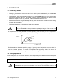
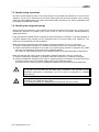
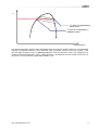
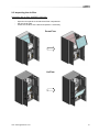
1
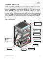
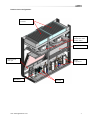
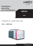
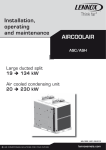
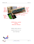
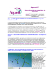
Installation, operating and maintenance INNOV@ ENERGY Close control units Centrifugal fans 4 240 kW INNOVA-ENERGY-IOM-0109-E lennoxemeia.com CONTENTS 1. GENERAL DESCRIPTION 1.1 Structure 1.2 Application limits 1.3 Cooling circuit 1.4 Installation warnings 2 4 4 5 8 2. INSPECTION 2.1 Inspection on receipt 2.2 Lifting and transport 2.3 Unpacking 2.4 Positioning 9 9 9 9 9 3. INSTALLATION 10 4. EVACUATION AND CHARGING OPERATIONS 4.1 Introduction 4.2 Vacuum and charging machine 4.3 Evacuating a circuit “contaminated” with refrigerant 4.4 Charging positions (single point) 11 11 11 12 12 5. ELECTRICAL CONNECTIONS 5.1 Generalities 13 13 6. OPERATING DIAGRAMS 14 7. STARTING UP 7.1 Preliminary checks 7.2 Starting operations 7.3 Checks during operations 7.4 Checking the refrigerant charge (DX versions) 15 15 15 16 16 8. SETTING OPERATING PARAMETERS 8.1 Generalities 8.2 Maximum pressure switch 8.3 Minimum pressure switch 18 18 18 18 9. MAINTENANCE 9.1 Warnings 9.2 Generalities 9.3 Inspecting the air filter 9.4 Set the right fan speed 9.5 Repairing the cooling circuit 9.6 Tightness test 9.7 Hard vacuum and drying of cooling circuit 9.8 Recharging with refrigerant R410A 9.9 Environmental protection 19 19 19 20 23 23 23 24 24 24 10. TROUBLESHOOTING 26 11. TECHNICAL DATA 28 12. REFRIGERANT PIPES 29 13. REFRIGERANT CHARGE 30 IOM / INNOV@-ENERGY-0109 1 1. GENERAL DESCRIPTION INNOV@ ENERGY CCAC self-contained units are specially designed for installation in technological environments such as Computer rooms, laboratories and in general where a high precision in climate control and a 24h/day operation are requested. INNOV@ ENERGY units represent the state of the art between technology and design as well as all factory products: thanks to their characteristics, INNOV@ ENERGY can be installed also in offices where people are working. The depth of 795 mm (600mm for INNOV@ ENERGY060) for all versions, allows the compatibility with standard electronic devices: furthermore the innovative design and the high tech selected colours make INNOV@ ENERGY units complementary to the last generation of IT devices. The internal design of the units in firstly made looking to efficiency and reliability but don't loosing accessibility: all components, including e-heaters, fans, compressors, valves, etc. can be maintained from the front and furthermore the door(s) are dismountable in few seconds thanks to an innovative hinge: this is very important when units are installed in small corridors. The exclusive use of primary brands components and a fully integrated development process (CAD+CAM, CAE) stands for highest possible quality level regarding efficiency, reliability, maintenance time, pre and after sales support. All the units are available both in single circuit up to 34,1 kW and up to 68,5 kW in double circuit. Single circuit configuration: Front extractable air filter Plug fan with alluminium wheel and EC motor Electrical panel Scroll compressor Stainless steel drain pan Oil separator Filter dryer Humidifier Inverter IOM / INNOV@-ENERGY-0109 Liquid receiver 2 Double circuit configuration: Front extractable air filters Plug fans with alluminium wheel and EC motor Electrical panel Stainless steel drain pan Humidifier IOM / INNOV@-ENERGY-0109 Scroll compressors Inverters 3 1.1 Structure INNOV@ ENERGY units are designed with a self supporting frame and all components are produced using sophisticated computer driven machines and special tools. All sheet metals are galvanized and all external panels are powder coated RAL 9002 giving to the units the image and the quality like last generation of IT devices. Units are completely closed and only frontal access is requested. Anyway it is also possible to have side access in order to reach the steam piping and the drain pan, or simply to substitute a damaged side panel: all this problems are very rare, but with INNOV@ ENERGY units it is possible to solve them. The shape of the units is characterized with the curved edges with variable radium as for all factory products: this feature is obtained using special tools and gives both a good aesthetic and advantages against injuries. The compressor compartment is separated from the air flow and the special internal design allows the simple dismounting of the upper part of it ensuring an insuperable accessibility to all refrigerating components. All fixing elements are made in stainless steel or in non corroding materials. The dray pan is made in stainless steel in order to ensure long time operation without damages. All panels are thermally insulated with a polyurethane foam class 1 according UL 94 norms: this material, thanks to the open cells, gives good performances in sound absorption. As an option, sandwich panels are available: in this case mineral fibres are closed between the panel and a second sheet of metal giving the maximum in terms of internal cleaning. Double skin panels are classified between non flammable materials class A1 according DIN 4102 norms : the sound insulation is better than the standard solution, but the internal reflected sound power will increase the amount in delivery side (+2dB). Power supply limits and Storage conditions for DX versions: Model INA..R Power supply Nominal Value +/-10% Storage conditions -10 / 90 % r.h. + 55 / 90 % r.h. 1.2 Application limits NA..R - Air condensed versions: Indoor air Temp. RH <= 65 % 32° 28° Condenser air Temp. 18 ° 20° 40° 45° NW..R - Water condensed versions: Indoor air T RH <= 65 % 32° 28° Condenser water Temp. 18 ° 25° IOM / INNOV@-ENERGY-0109 40° 43° 4 1.3 Cooling circuit The entire refrigerating circuit is assembled in our warehouse including all pipe work and using only primary brand for components. The workers involved in the welding and pipe work process are qualified by a third part according CEE 97/23 PED directive: it is worth to be underlined that this qualification for workers were not request, but it is our own decision taking care of the quality and/or in general to the customer satisfaction. All DX unit (“A”, “W”, “F”, “D”, “Q” versions) are prechargerd with dry nitrogen for “A”, “D” or with R410A refrigerant for “W”, “F”, “Q” versions. Compressors: on INNOV@ ENERGY units only primary brand scroll compressors in special execution for inverter application motor, are installed (excepted the 060 model in which a rolling piston compressor are installed). Scroll compressor represents for CCAC units the best solution in terms of efficiency and reliability. The internal compression ratio is very close to the typical operating condition of CCAC giving the maximum in terms of COPs and the perfect balanced pressures at start up gives big advantages to the e_motor in terms of reliability, mainly in this filed where frequent start up may be possible. All motors are thermally protected with an internal sensors chain: in case of overload this sensor opens without giving contacts to the connection box. Cooling components: o Molecular mesh activated-alumina filter dryer o Flow indicator with humidity indicator. Indications are provided directly on the sight glass. o electronic driven valves o High and low pressure switches o Schrader valves for checks and/or maintenance Electric control board: The electric control board is constructed and wired in accordance with Directives 73/23/EEC and 89/336/EEC and related standards. The board may be accessed through a door after the main switch has been turned off. All the remote controls use 24 V signals powered by an insulating transformer situated on the electric control board. NOTE: the mechanical safety devices such as the high pressure switch are of the kind that trigger directly; their efficiency will not be affected by any faults occurring in the microprocessor control circuit, in compliance with 97/23 PED. Control microprocessor: the microprocessor built into the unit allows the different operating parameters to be controlled from a set of pushbuttons situated on the electric control board; o Switching on/off of compressor(s) to maintain the temperature set point T inside the shelter o Alarm management High / low pressure Dirty filters alarm (optional) Air flow alarm o Alarm signalling o Display of operating parameters o RS232, RS485 serial output management (optional) o Phase sequence error [Not displayed by the mP, but prevents the compressor from starting up] [see microprocessor control manual for further details, also in relation to particular customer specifications] IOM / INNOV@-ENERGY-0109 5 Basic cooling circuit for DX versions (1 circuit): Ref. Description Ref. Description 11 Condenser 12 13 14 15 16 Flooding valve Safety valve Check valve Solenoid valve Hot gas coil (opt.) Hot gas check valve opt. Hot gas thermostatic valve opt. Hot gas solenoid valve opt. 2 3 4 5 6 Inverter driver compressor HP Pressure switch Pressure probe (opt.) Ball valve Refrigerant filter Sight glass 7 Thermostatic valve 17 8 Evaporator 18 9 LP pressure switch 19 10 Liquid receiver 1 IOM / INNOV@-ENERGY-0109 6 Basic cooling circuit for DX versions (2 circuits): Rif. 1 2 3 4 5 6 7 8 IOM / INNOV@-ENERGY-0109 Descrizione Inverter driver compressor HP Pressure switch Pressure probe (opt.) Ball valve Refrigerant filter Sight glass Thermostatic valve Evaporator Rif. Descrizione 9 LP pressure switch 10 11 12 13 14 15 Liquid receiver Condenser Flooding valve Safety valve Check valve Solenoid valve 7 1.4 Installation warnings General rules - When installing or servicing the unit, you must strictly follow the rules provided in this manual, comply with the directions on the units themselves and take all such precautions as are necessary. - The fluids under pressure in the cooling circuit and the presence of electrical components may cause hazardous situations during installation and maintenance work. All work on the unit must be carried out by qualified personnel only, trained to do their job in accordance with current laws and regulations. - Failure to comply with the rules provided in this manual or any modification made to the unit without prior authorisation will result in the immediate invalidation of the warranty. Warning: Before performing any kind of work on the unit, make sure it has been disconnected from the power supply. IOM / INNOV@-ENERGY-0109 8 2. INSPECTION / TRANSPORT / POSITIONING 2.1 Inspection on receipt On receiving the unit, check that it is perfectly intact: the unit left the factory in perfect conditions; immediately report any signs of damage to the carrier and note them on the Delivery Slip before signing it. Lennox or its agent must be promptly notified of the entity of the damage. The Customer must submit a written report describing every significant sign of damage. 2.2 Lifting and Transport While the unit is being unloaded and positioned, utmost care must be taken to avoid abrupt or violent manoeuvres. The unit must be handled carefully and gently; avoid using machine components as anchorages or holds and always keep it in an upright position. The unit should be lifted using the pallet it is packed on; a transpallet or similar conveyance means should be used. Warning: In all lifting operations make sure that the unit is securely anchored in order to prevent accidental falling or overturning. 2.3 Unpacking The packing must be carefully removed to avoid the risk of damaging the unit. Different packing materials are used: wood, cardboard, nylon etc. It is recommended to keep them separately and deliver them to suitable waste disposal or recycling facilities in order to minimise their environmental impact. 2.4 Positioning Bear in mind the following aspects when choosing the best site for installing the unit and the relative connections: - positioning and dimensions of the coupling flanges; - location of power supply; - solidity of the supporting floor; It is recommended to first prepare holes in the floor/wall for passing through the power cables and for the air outlet (down flow units). The dimensions of the air outlet and the positions of the holes for the screw anchors and power cables are shown in the dimensional drawings. IOM / INNOV@-ENERGY-0109 9 3. INSTALLATION The INNOV@ ENERGY air-conditioning unit is suitable for all environments except aggressive ones. Do not place any obstacles near the units and make sure that the air flow is not impeded by obstacles and/or situations causing back suction. MODEL A(mm) B(mm) C(mm) D(mm) E(mm) INADR0060 - INAUR0060 INADR0130 - INAUR0130 INADR0281 - INAUR0281 INADR0592 - INAUR 0592 600 900 1270 2020 650 650 750 750 600 600 795 795 10 10 10 10 1875 1875 1998 1998 The following steps should be carried out to ensure proper installation: Apply a anti-vibration rubber lining between the unit and the bottom Position the unit on the floor / floorstand (base frame) The recommended sizes for the power cables and emergency line are shown in the table below: Model unit INADR0060-INAUR0060 INADR0130-INAUR0130 INADR0281-INAUR0281 INADR0592-INAUR0592 IOM / INNOV@-ENERGY-0109 Main power supply Cable type 4x2,5 mmq + T 2,5mmq 400V/3Ph+N/50Hz 4x6 mmq + T 6mmq 4x16 mmq + T 16mmq 4x25 mmq + T 16mmq 10 4. EVACUATION AND CHARGING OPERATIONS This type of work must be carried out by qualified personnel only trained to do their job in accordance with current laws and regulations. 4.1 Introductions The contemporaneous presence of liquid and vapour requires for both to be in a state of saturation [Gibb’s law], as shown in the fig. 1. In thermal equilibrated conditions, the pressure in the tank corresponds to the ambient temperature. Withdrawal of refrigerant from the tank has following effects: - withdrawal of refrigerant charge - pressure drop inside the tank - T drop & change of status - cooling of liquid pressure drop inside the tank T drop & change of status evaporation of part of the liquid, causing a cooling down of the liquid thermal exchange with ambient air, further evaporation of remaining liquid; the original pressure in the tank will be restored after a certain period of time T tank/ambient P fig. 1 Saturated gas Saturated liquid Enthalpy h 4.2 Vacuum and charging machine Vacuum cycle In general it is better to apply a “long” rather than a “hard” vacuum: reaching a low pressure too abruptly may in fact cause that any remaining humidity evaporates instantaneously, thus freezing part of it. P [Pa] fig. 3 150 6 200 s IOM / INNOV@-ENERGY-0109 Time 11 The fig.3 represents a vacuum cycle and an optimal subsequent pressure rise for the refrigeration devices we manufacture. Generally in bigger refrigeration systems or if there is a suspicion of an extensive quantity of humidity in the refrigeration circuit, the vacuum needs to be “broken” by using anhydrous nitrogen. Then the steps of evacuation need to be repeated as described before. This operation facilitates the removal of remaining and/or frozen humidity during the evacuation process. 4.3 Evacuating a circuit “contaminated” with refrigerant The first step is to remove the refrigerant from the circuit. To do this a specific machine is necessary with a drying compressor in order to recover the refrigerant. Refrigerants all tend to dissolve in oil [compressor sump]. The "Oil" figure illustrates a specific property [Charles’ Law] of gases, which are more soluble in liquids as the pressure increases but less soluble as the temperature increases. T oil Pressure T3 T2 T1 “Oil” fig. % of refrigerant in oil If the oil in the sump is held at a constant pressure, an increase in temperature will significantly reduce the amount of refrigerant dissolved in it, thus ensuring that the lubricating function desired is maintained. The problem of inadequate lubrication occurs if the crankcase is not duly heated, above all after seasonal interruptions when, due to the suction effect of the compressor, there is an abrupt drop in pressure inside the sump, which results in considerable evaporation of the refrigerant previously dissolved in the oil. If heating elements were not installed, this phenomenon would cause two problems: The release of refrigerant from the cooling circuit tends to cool down the oil and thus actually creates the opposite effect by keeping more refrigerant dissolved in the oil: for this reason, it is advisable to switch on –if available- the crankcase heater during the evacuation process. If a high % of refrigerant gets in contact with the Pirani gauge (vacuum sensor), it may “mislead” this sensitive sensor and misinterpret the value for a certain period of time. For this reason -if no machine for recovering refrigerant is available- it is nonetheless advisable to switch on the crankcase heater and to avoid full vacuum before the circuit has been adequately purged of refrigerant. The refrigerant may in fact dissolve in the oil of the vacuum pump, reducing its performance for a long time (hours). 4.4 Charging position (single point) The best position to charge the unit is the section between the thermostatic valve and the evaporator. Take care to avoid the fixing of the thermostat bulb until the operation is completed. It is important to ensure that the valve orifice remains open in order to allow the passage of refrigerant also towards the condenser / liquid receiver. If possible, avoid the charge of refrigerant into the suction line of the compressor as this may cause excessive dilution of the lubricant. In any case verify first the necessary volume of the crankcase and compare it with the required charge volumes. IOM / INNOV@-ENERGY-0109 12 5. ELECTRICAL CONNECTIONS 5.1 Generalities Before carrying out any job on electrical parts, make sure the power supply is disconnected. Check that the mains electricity supply is compatible with the specifications (voltage, number of phases, frequency) shown on the unit rating plate. The power connection for single-phase loads is to be made with a three-pole cable and “N” wire at the centre of the star [optional: power supply w/o neutral]. The size of the cable and line protections must conform to the specifications provided in the wiring diagram. The supply voltage may not undergo fluctuations exceeding ±5% and the unbalance between phases must always be below 2%. The above operating conditions must always be complied with: failure to ensure said conditions will result in the immediate invalidation of the warranty. The electrical connections must be made in accordance with the information shown in the wiring diagram provided with the unit and with current and local regulations. An earth connection is mandatory. The installer must connect the earthing wire using the earthing terminal situated on the electric control board (yellow and green wire). The power supply to the control circuit is taken from the power line through an insulating transformer situated on the electric control board. The control circuit is protected by suitable fuses or automatic breakers depending on the unit size. Never connect the inverter driven compressors directly to the 400/3/50 power supply. IOM / INNOV@-ENERGY-0109 13 6. OPERATING DIAGRAMS IN_DR IOM / INNOV@-ENERGY-0109 IN_UR IN_XR 14 7. STARTING UP 7.1 Preliminary checks - Check that the electrical connections have been made properly and that all the terminals are securely tightened. This check should also be included in a periodic six-month inspection. - Check that the voltage at the RST terminals is 400 V ± 5% and make sure the yellow indicator light of the phase sequence relay is on. The phase sequence relay is positioned on the electric control board; if the sequence is not duly observed, it will not enable the machine to start. - Make sure there are no refrigerant leakage that may have been caused by accidental impacts during transport and/or installation. - Check the power supply to the crankcase heater, where present. The heating elements must be turned on at least 12 hours before the unit is started. They are automatically activated when the main switch is put on. Their function is to raise the T of the oil in the sump and limit the quantity of refrigerant dissolved in it. To verify whether the heating elements are working properly, check the lower part of the compressors: it should be warm or in any case at a temperature 10 - 15 °C higher than the ambient temperature. Pressure Oil T % R407C in oil The diagram above illustrates a specific property of gases [Charles’ Law], which are more soluble in liquids as the pressure increases but less soluble as the temperature increases: if the oil in the sump is held at a constant pressure, an increase in temperature will significantly reduce the amount of refrigerant dissolved in it, thus ensuring that the desired lubricating function is maintained. 7.2 Starting operations Before starting the unit, turn the main switch on, select the operating mode desired from the control panel and press the "ON" button on the control panel. If the unit fails to start up, check if the service thermostat has been set according to the nominal values provided. You should not disconnect the unit from the power supply during periods when it is inoperative but only when it is to be taken out of service for a prolonged period (e.g. at the end of the season). IOM / INNOV@-ENERGY-0109 15 7.3 Checks during operations - Check the phase sequence relay on the control board to verify whether the phases occur in the correct sequence: if they do not, disconnect the unit from power supply and invert two phases of the incoming three-pole cable. Never attempt to modify internal electrical connections: any undue modifications will immediately invalidate the warranty. 7.4 Checking the refrigerant charge - After a few hours of operation, check whether the liquid level indicator has a green ring: a yellow colour indicates the presence of humidity in the circuit. In such a case the circuit must be dehumidified by qualified personnel. - Large quantities of bubbles should not appear through the liquid level indicator. A constant passage of numerous bubbles may indicate that the refrigerant level is low and needs to be topped up. The presence of a few bubbles is however allowed. - Make sure that the refrigerant gas super-heating is limited to between 5 and 8 °C: to this end: 1) read the temperature indicated by a contact thermometer placed on the compressor intake pipe; 2) read the temperature indicated on the scale of a pressure gauge likewise connected to the intake side; refer to the pressure gauge scale for the refrigerant R410A. The degree of super-heating is given by the difference between the temperatures thus determined. - Make sure that the Sub-cooling of the cooling fluid is limited to between 3 and 5°C: to this end: 1) read the temperature indicated by a contact thermometer placed on the condenser outlet pipe; 2) read the temperature indicated on the scale of a pressure gauge connected to the liquid inlet at the condenser outlet; refer to the pressure gauge scale for the refrigerant R410A. The degree of Sub-cooling is given by the difference between the temperatures thus determined. Warning: all the air condensed INNOV@ ENERGY units are charged with dry nitrogen. Any top-ups must be made using the same type of refrigerant. This operation is to be considered extraordinary maintenance work and must be performed by qualified personnel only. Warning: the refrigerant R410A requires “PVE” polyester oil of the type and viscosity indicated on the compressor rating plate. For no reason should oil of a different type be introduced into the oil circuit. IOM / INNOV@-ENERGY-0109 16 P T1 (start of condensation) DEW POINT T2 (end of condensation) BUBBLE POINT Heat content h The difference between the Dew Point and Bubble Point is known as “GLIDE” and this is a characteristic property of refrigerant mixtures. If pure fluids are used, the phase change occurs at a constant T and thus the glide is equal to zero. In INNOV@ ENERGY units HFC R410A is used. This refrigerant is a mixture of R32 and R125 (50% - 50%), nearly azeotropic. Its behaviour is much similar to that one of a pure fluid: in fact it introduces a glide approximately 0,1°C. IOM / INNOV@-ENERGY-0109 17 8. SETTING OPERATING PARAMETERS 8.1 Generalities All the control devices are set and tested in the factory before the unit is dispatched. However, after the unit has been in service for a reasonable period of time you can perform a check on the operating and safety devices. The settings are shown in Table II. All servicing of the equipment is to be considered extraordinary maintenance and may be carried out BY QUALIFIED TECHNICIANS ONLY: incorrect settings may cause serious damage to the unit and injuries to persons. The operating parameters and control system settings configurable by means of the microprocessor control are password protected if they have a potential impact on the integrity of the unit. TABLE II - SETTING OF CONTROL DEVICES CONTROL DEVICE SET POINT Differential air pressure switch (air Pa flow) Differential air pressure switch (dirty Pa filter) CONTROL DEVICE Maximum pressure switch Minimum pressure switch Modulating condensation control devices (DX versions) Time lapse between two compressor starts DIFFERENTIAL 50 30 70 20 ACTIVATION DIFFERENTIAL RESETTING Bar-g Bar-g Bar-g 42.0 2 14 13.0 1.3 7 Manual Automatic - s 480 - - 8.2 Maximum pressure switch The high pressure switch stops the compressor when the outlet pressure exceeds the set value. Warning: do not attempt to change the setting of the maximum pressure switch: Should the latter fail to trip in the event of a pressure increase, the pressure relief valve will open. The high pressure switch must be manually reset; this is possible only when the pressure falls below the differential set (see Table II). 8.3 Minimum pressure switch The low pressure switch stops the compressor when the inlet pressure falls below the set value for more than 180 seconds. The switch is automatically reset when the pressure rises above the set differential (see Table II). IOM / INNOV@-ENERGY-0109 18 9. MAINTENANCE The only operations to be performed by the user are to switch the unit on and off. All other operations are to be considered maintenance work and must thus be carried out by qualified personnel trained to do their job in accordance with current laws and regulations. 9.1 Warnings All the operations described in this chapter MUST ALWAYS BE PERFORMED BY QUALIFIED PERSONNEL ONLY. Before carrying out any work on the unit or accessing internal parts, make sure you have disconnected it from the mains electricity supply. The upper part and the outlet pipe of the compressor reach high temperatures. Be especially careful when working in the surrounding area with the panels off. Be especially careful when working in proximity to finned coils since the 0.11 mmthick aluminium fins can cause superficial injuries due to cuts. After completing maintenance jobs, always replace the panels enclosing the units and secure them with the fastening screws provided. 9.2 Generalities To guarantee a constantly satisfactory performance over time, it is advisable to carry out routine maintenance and checks as described below. The indications below are related to standard tear and wear. Operation Frequency Check the efficiency of all the control and safety devices Once a year Check the terminals on the electric control board and compressor terminal boards to ensure that they are securely tightened. The movable and fixed contacts of the circuit breakers must be periodically cleaned and replaced whenever they show signs of deterioration. Check the refrigerant level by means of the liquid level indicator Check the efficiency of the differential air pressure switch and dirty filter differential pressure switch Check the condition of the air filter and replace it if necessary Check the humidity indicator (green=dry, yellow=humid) on the liquid level indicator; if the indicator is not green as shown on the indicator sticker, replace the filter Once a year IOM / INNOV@-ENERGY-0109 Every 6 months (DX) Every 6 months Every 6 months Every 6 months (DX) 19 9.3 Inspecting the air filter Inspecting the air filter (MODELS 060-130) Open the front panels to access the air filter compartment. Pull out the air filter. Check the condition of the filter and replace it if necessary Down-Flow Up-Flow IOM / INNOV@-ENERGY-0109 20 Inspecting the air filter (MODELS 281-592) DOWN-FLOW version Open the front panels to access the air filter compartment. Pull out the air filter. Check the condition of the filter and replace it if necessary IOM / INNOV@-ENERGY-0109 21 UPFLOW version: Open the front panels to access the air filter compartment. Remove the screws(*) and the metallic support [ (*) no need for tools ] Extract the filter on the right. Pull on the right side the second filter and then extract it. IOM / INNOV@-ENERGY-0109 22 9.4 Set the right fan speed The adopted fans are of the backward curved blades type in combination with EC motor. This kind of fan has very high performances so that it’s speed has to be reduced in order to match to the nominal air flow with the real external pressure drops: in case of wrong selection, the air flow may exceed the limits with possible water dragging out from the coils (down flow units). External pressure drops DP (Pa) Unit performance @ full speed Unit performance @ intermediate speed Unit performance @ low speed Nominal Air flow Air flow Air flow over the limits In the EC fans the rotation speeds are selected with different values of the control tension (0 – 10V). The right value of the control tension has to be set by keyboard, considering the AESP requested on site. If the unit is equipped with the “air flow control” option, the mp manage the fan speed in order to obtain the required air flow (Air flow set-point). 9.5 Repairing the Cooling Circuit Warning: while performing repairs on the cooling circuit or maintenance work on the compressors, make sure the circuit is left open for as less time as possible. Even if briefly exposed to air, ester oils tend to absorb large amounts of humidity, which results in the formation of weak acids. If the cooling circuit has undergone any repairs, the following operations must be carried out: - tightness test; - evacuation and drying of the cooling circuit; - charging with refrigerant. If the system has to be drained, always recover the refrigerant present in the circuit using suitable equipment; the refrigerant should be handled exclusively in the liquid phase. 9.6 Tightness test Fill the circuit with anhydrous nitrogen supplied from a tank with a pressure-reducing valve until the pressure rises to 22 bars. During the pressurisation phase, do not exceed a pressure of 22 bars on the compressor low pressure side. The presence of any leaks must be determined using special leak detectors. Should any leaks be detected during the test, empty out the circuit before repairing the leaks with suitable alloys. IOM / INNOV@-ENERGY-0109 23 Do not use oxygen in the place of nitrogen as a test agent, since this would cause a risk of explosion. 9.7 Hard Vacuum and Drying of Cooling Circuit To achieve a hard vacuum in the cooling circuit it is necessary to use a pump capable of generating a 3 high degree of vacuum, i.e. 150 Pa of absolute pressure with a capacity of approximately 10 m /h. If such a pump is available, one evacuation will normally suffice to achieve an absolute pressure of 150 Pa. If there is no such vacuum pump available, or whenever the circuit has remained open for long periods of time, you are strongly recommended to adopt the triple evacuation method. This method is also recommended when there is a presence of humidity within the circuit. The vacuum pump should be connected to the inlets. The procedure to be carried out is as follows: - Evacuate the circuit until you reach an absolute pressure of at least 350 Pa: at this point inject nitrogen into the circuit until you reach a relative pressure of about 1 bar. - Repeat the step described above. - Carry out the step described above for the third time, but in this case attempting to reach the hardest vacuum possible. Using this procedure you can easily remove up to 99% of pollutants. 9.8 Recharging with refrigerant R410A - Connect the tank of refrigerant gas to the male 1/4 SAE inlet situated on the liquid line after discharging a little gas to eliminate air in the connection pipe. - Fill with refrigerant in liquid form until you reach 75% of the total charge. - Then connect to the inlet on the pipe between the thermostatic valve and evaporator and complete the charging process with the refrigerant in liquid form until no more bubbles can be seen on the liquid level indicator and the operating parameters specified in this manual have been reached. Since R410A is a binary mixture, charging must take place exclusively with liquid refrigerant to ensure the correct percentages of the two constituents. Introduce refrigerant through the inlet in the liquid line. A unit that was originally made to be charged with R410A, must not be charged other refrigerants without the written authorisation of Lennox. 9.9 Environmental protection The law implementing the regulations [reg. EEC 2037/00] which govern the use of ozone-depleting substances and greenhouse gases bans the dispersal of refrigerant gases in the environment and requires whoever is in their possession to recover them and, at the end of their useful life, either to return them to the dealer or take them to a suitable waste disposal facility. IOM / INNOV@-ENERGY-0109 24 The refrigerant HFC R410A is not harmful to the ozone layer but is included among the substances responsible for the greenhouse effect and thus falls within the scope of the aforesaid regulations. Therefore, special care should be taken when carrying out maintenance work to minimise refrigerant leaks. IOM / INNOV@-ENERGY-0109 25 10. TROUBLESHOOTING On the next pages you will find a list of the most common reasons that may cause the package unit to fail or any malfunction. This causes are broken down according to easily identifiable symptoms. You should be extremely careful when attempting to implement any of the possible remedies suggested: overconfidence can result in injuries, even serious ones, to inexpert individuals. Therefore, once the cause has been identified, you are advised to contact the manufacturer or a qualified technician for help. FAULT The unit does not start. Possible causes Corrective actions Check if power is being supplied both to the primary and auxiliary circuits. The electronic card is cut off from Check the fuses. the power supply. Alarms have been released. Check whether any alarms are signalled on the microprocessor control panel, eliminate the causes and restart the unit. The phase sequence is wrong. Invert two phases in the primary power line after disconnecting them upstream from the unit. The compressor is noisy. The compressor is rotating in the Check the phase sequence relay. wrong direction. Invert the phases on the terminal board after disconnecting the unit and contact the manufacturer. Presence of abnormally high Insufficient airflow through the Check for the presence of pressure. condenser. obstructions in the condenser section ventilation circuit. Check whether the condenser coil surface is obstructed. Check the condensation control device [optional]. Presence of air in the refrigerant Drain and pressurise the circuit circuit, as revealed by the and check for leaks. Evacuate presence of bubbles in the flow slowly [for more than 3 hours] until indicator also with sub-cooling reaching a pressure of 0.1 Pa and values exceeding 5 °C. then recharge in the liquid phase. IOM / INNOV@-ENERGY-0109 No power supply. 26 FAULT Presence of abnormally high pressure. Low condensation pressure. Low evaporation pressure. Possible causes Unit overcharged, as revealed by a Sub-cooling of more than 8 °C. Thermostatic valve and/or filter obstructed. These symptoms may also occur in the presence of an abnormally low pressure. Transducer fault. Malfunctioning valve. of thermostatic Filter dryer clogged. Low condensation T. Low level of refrigerant. The internal thermal protection device has tripped. The compressor does not start. Water out from the unit. Water out from the unit. Water out from the unit. IOM / INNOV@-ENERGY-0109 The circuit breakers or line fuses have been tripped by a short circuit. Corrective actions Drain the circuit. Check the temperatures upstream and downstream from the valve and filter and replace them if necessary. Check the efficiency of the condensation control device [optional]. Warming the bulb with your hand, check whether the valve opens and adjust it if necessary. If it does not respond, replace it. Pressure drops upstream and downstream from the filter should not exceed 2°C. If they do, replace the filter. Check the efficiency of the condensation control device [where present]. Check the refrigerant level by measuring the degree of Subcooling; if it is below 2°C replenish the charge. In the case of compressors equipped with a protection module, check the thermal contact. Identify the causes after restarting. Pinpoint the cause by measuring the resistance of the individual windings and the insulation from the casing before restoring power. Check on the microprocessor, eliminate the causes. Check the phase sequence relay. One of the high or low pressure switches has tripped. The phases have been inverted in the distribution compartment. The drain pan hole is closed. Open the front panels, remove the sheet metal just below the e-panel (Down Flow units) and clean it. The siphon is missing. Check for the presence and provide for a new one. The Air flow is too high. Reduce the fan speed up to reaching the nominal air flow. 27 11. TECHNICAL DATA INNOV@ ENERGY Model Air Flow Sound pressure level * Compressor Type Cooling Capacity Cp Power Consumption Speed Absorbed Current 30Hz SHR Cooling Capacity Cp Power Consumption Speed Absorbed Current 70Hz SHR Cooling Capacity Cp Power Consumption Speed 110Hz Absorbed Current SHR FLA LRA PVE Oil charge Finned coil evaporator Front Surface Geometry Rows Type of fins Fin pitch Indoor fan Type Power supply Number of fans Fans absorbed current ** Fans absorbed power ** AESP nominal fan speed AESP (maximum speed) ** Air Filter Filtration Overall surface Fire class resistance Electrical heaters Total Heating Capacity Material Humidifier Max capacity Absorbed power Frame H L D Weight 0060 0130 0281 0592 [ [ 1.785 47 3.700 52 7.280 54 14.150 63 [ kW ] [ kW ] [A] [-] [ kW ] [ kW ] [A] [-] [ kW ] [ kW ] [A] [-] [A] [A] [l] Rolling piston 3,2 0,8 4,2 1,00 6,3 2,0 10,2 0,94 9,5 3,2 16,3 0,80 15,7 0,6 Scroll 6,3 1,2 2,1 1,00 11,0 3,3 5,5 1,00 15,8 5,3 9,0 0,85 13,1 0,75 Scroll 24,4 4,7 8,1 1,00 43,9 12,7 21,5 0,95 62,9 20,5 34,7 0,80 25,3 2,3 Scroll 24,4 4,7 8,1 1,00 43,9 12,7 21,5 0,95 62,9 20,5 34,7 0,80 44,8 2,3 x 2 0,28 25 x 22 4 Hydrofilic 1,8 0,50 25 x 22 3 Hydrofilic 1,8 0,90 25 x 22 5 Hydrofilic 2,1 1,55 25 x 22 4 Hydrofilic 2,1 Radial-EC 400/3/50 1 0,21 130 30 578 Radial-EC 400/3/50 1 0,65 410 30 426 Radial-EC 400/3/50 1 1,81 1.130 30 328 Radial-EC 400/3/50 2 4,0 2.480 30 304 [m2] G3 0,63 1 G3 1,03 1 G3 1,75 1 G3 3,51 1 [kW] [-] 1,6 Alluminium 3,2 Alluminium 6,4 Alluminium 9,6 Alluminium [ kg/h [ kW] 3,0 2,25 3,0 2,25 8,0 6,00 8,0 6,00 [mm] [mm] [mm] 1.875 600 600 1.875 900 600 1.998 1.270 795 1.998 2.020 795 [ kg ] 160 250 515 998 [m2] [-] [-] [ mm [V[A] [W ] [ Pa ] [Pa] (*) At 1,5 meter height, 2 meters frontal distance in free field – down flow units (30Pa AESP), nominal air flow, cp speed 50Hz (**) Values referred to down flow units (30Pa AESP) The performances are given considering the units in combination with the suggested remoter condensesr and with an outside air T = 35°C. IOM / INNOV@-ENERGY-0109 28 12. REFRIGERANT PIPES On site piping has to be installed by professional workers using only CUB quality copper pipes. Take care in use of nitrogen during all brazing operations in order to avoid humidity and dirty in pipes. Refrigerant R410A R410A R410A INNOV@ ENERGY Model 0281-0592 0130 0060 HP horizontal Gas line [Inch] [mm] 15,88 5/8 12,70 1/2 9,53 3/8 Hp vertical Gas line [mm] [Inch] 12,70 1/2 9,53 3/8 7,94 5/16 Liquid line [mm] [Inch] 12,70 1/2 9,53 3/8 9,53 3/8 Table up to 10 m of pipe length The declared performances are calculated for a max lines length of 10m, in the next table, the absorbed compressor power and the cooling capacity variation percentage for 20m lines, are showed: 0281-0592 INNOV@ ENERGY Model Frequency 30Hz 90Hz 0130 110Hz 30Hz 90Hz 0060 110Hz 30Hz 90Hz 110Hz Cooling Capacity [%] -0.43 -1.37 -1.80 -0.10 -1.05 -1.70 -0.10 -1.71 -2.86 Power Consumption [%] +0.25 +1.59 +2.48 +0.54 +1.27 +1.72 +0.54 +2.35 +3.36 Standard Copper pipes Diameter [mm] Thickness [mm] Minimum bending radius [mm] 10 12 16 18 22 28 35 42 54 1 1 1 1 1,5 1,5 1.5 1.5 2.0 36 36 46 56 67 96 70 84 108 IOM / INNOV@-ENERGY-0109 System design pressure PS [bar] 42 42 42 42 42 42 42 42 42 PED Category Max Copper σs [N/mm2] Real copper σ [N/mm2] Safety ratio A3 P3 A3 P3 A3 P3 A3 P3 A3 P3 A3 P3 A3P3 A3P3 A3P3 227 227 227 227 227 227 227 227 227 16.8 21.0 29.4 33.6 26.6 35.0 44.8 54.6 52.5 13.5 10.8 7.7 6.8 8.5 6.5 5.0 4.2 4.3 29 13. REFRIGERANT CHARGE The following table gives an idea of the total refrigerant charge: this should be used just as first reference but the right charge should be performed on site by a qualified installer . Note: The INNOV@ ENERGY units as well as the remote condenser are shipped filled with nitrogen or dry air. 0281-0592* 0130 0060 [kg] 3.080 2.190 1.210 [kg] 3.870 1.780 1.490 [kg] 5.350 3.870 1.780 [kg/m] 0.130 0.080 0.070 INNOV@ ENERGY Model Unit Charge Air Cooled Condenser Charge (standard unit) Air Cooled Condenser Charge (low noise unit) Charge for liquid line Note: approximated values (± 20%), to be verified on site. (*) Values referred to each circuit IOM / INNOV@-ENERGY-0109 30 lennoxemeia.com SALES OFFICES : BELGIUM AND LUXEMBOURG + 32 3 633 3045 FRANCE +33 1 64 76 23 23 GERMANY +49 (0) 40 589 6235 0 ITALY + 39 02 495 26 200 RUSSIA +7 495 626 56 53 SPAIN +34 902 533 920 UKRAINE +38 044 585 59 10 UNITED KINGDOM AND IRELAND +44 1604 669 100 NETHERLANDS + 31 332 471 800 POLAND +48 22 58 48 610 PORTUGAL +351 229 066 050 OTHER COUNTRIES : LENNOX DISTRIBUTION +33 4 72 23 20 00 Due to Lennox’s ongoing commitment to quality, the specifications, ratings and dimensions are subject to change without notice and without incurring liability. Improper installation, adjustment, alteration, service or maintenance can cause property damage or personal injury. Installation and service must be performed by a qualified installer and servicing agency INNOVA-ENERGY-IOM-0109-E