1
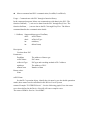
EB8000 User Manual
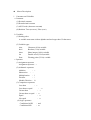
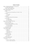
Table of Contents
Chapter 1
Chapter 2
Chapter 3
Chapter 4
Chapter 5
Chapter 6
Chapter 7
Chapter 8
Chapter 9
Chapter 10
Chapter 11
Chapter 12
Chapter 13
Chapter 14
Chapter 15
Chapter 16
Chapter 17
Chapter 18
Chapter 19
Chapter 20
Chapter 21
Addresses)
Chapter 22
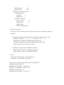
guid
EasyBuilder 8000 Installation
Project Manager Operations
How to Create a Simple Object
Compiling, Simulation and Downloading
System Parameters
Window Operations
Event Log
Data Sampling
Object’s General Attributes
Object’s Security Guard
Index Register
Designing and Using Keypad
Object
Creating and Using Shape Library and Picture Library
Label Library & Using Multi-Language
Creating and Using Address Tag Library
Transferring Recipe Data
Macro User’s Manual
Exemplification
Ethernet Communication and Multi-HMIs Connection
HMI State Controlling (System Reserved Register
EasyView MT8000 seires HMI and PLC connecting
EB8000 Serial User Guide
Chapter 1
EasyBuilder 8000 Installation
EasyBuilder 8000 Installation
(1) Software:
Download from EasyBuilder 8000 CD or visit Weintek Labs, Inc.’s website at
http://www.weintek.com to obtain all available software editions (including
Simplified Chinese, Traditional Chinese and English version) and latest upgraded
files.
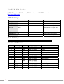
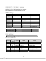
(2) Hardware Requirements (Recommended):
CPU: INTEL Pentium II or above
Memory: 64MB or above
Hard Disk: 2.5GB or above (Disc space available at least 10MB)
CD-ROM: 4X or above
Display: 256 color SVGA with 800 x 600 resolution or greater
Keyboard and Mouse: One for each
Ethernet: for project downloading/uploading
RS-232 COM: At least one RS-232 serial port available for on-line simulation
Printer
(3) Operating System:
Windows 2000/Windows NT/Windows XP
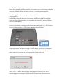
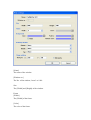
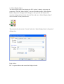
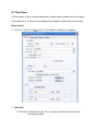
(4) Installation:
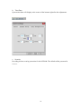
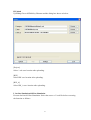
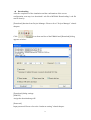
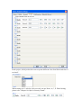
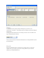
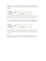
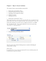
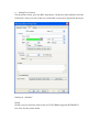
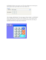
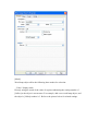
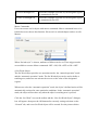
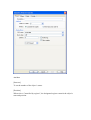
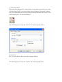
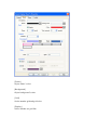
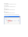
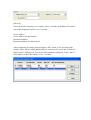
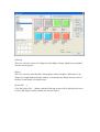
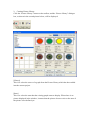
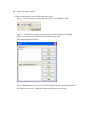
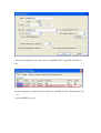
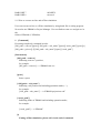
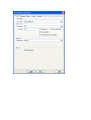
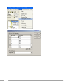
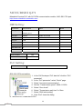
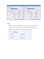
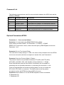
1) When putting the EB8000 CD into CD Rom, the Autorun program will
automatically execute by computer. Or run [Anutorun.exe] from the root directory
manually and the screen shows as below:
1
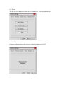
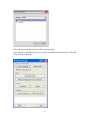
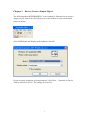
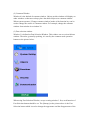
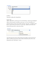
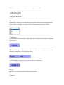
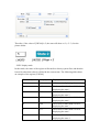
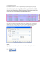
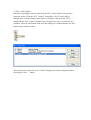
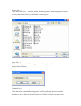
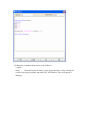
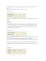
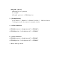
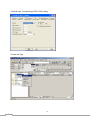
2) Click [Install] and the screen appears as below:
2
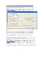
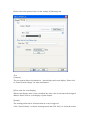
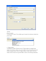
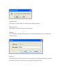
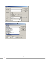
3) Follow the instructions and click [Next].
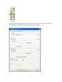
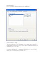
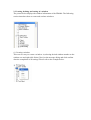
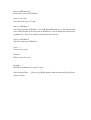
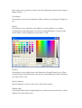
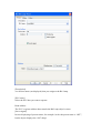
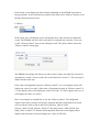
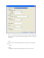
4) Select the target file for software installation or select suggestive path and then
click [Next].
3
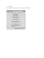
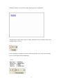
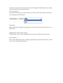
Click “Next” to confirm the installation.
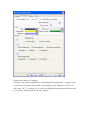
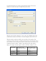
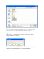
Installation processing
Click” Close” to complete the installation.
4
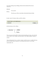
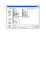
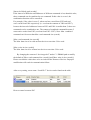
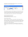
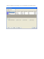
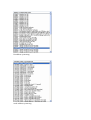
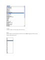
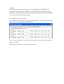
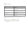
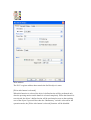
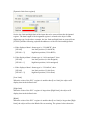
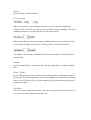
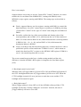
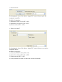
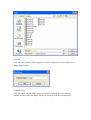
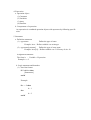
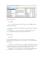
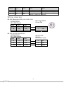
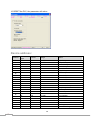
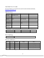
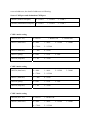
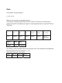
5) Choosing menu [Start] / [Programs] / [EasyBuilder8000] to start the program.
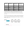
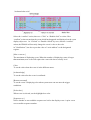
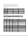
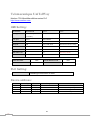
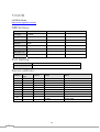
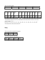
The identification of each selection under the directory of the software:
EasyBuilder8000
EB8000 touch screen editing
software
EasyConverter
Data record conversion tool
Project Manager
MT8000 integration management
software
ReleaseNote.pdf
Software version and latest
information
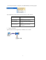
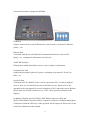
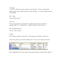
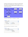
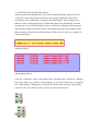
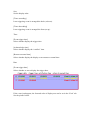
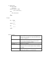
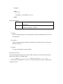
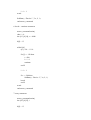
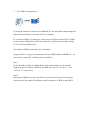
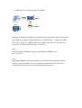
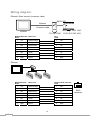
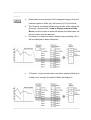
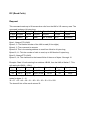
2. System Connection
Typical connection for the application of MT8000 series as below:
5
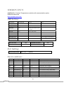
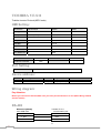
Connection interfaces equipped in MT8000:
USB Host
Support various devices with USB interface, such as mouse, keyboard, USB stick,
printer…etc.
Ethernet Port
Connected with devices with Ethernet communication function, such as PLC,
laptop…etc; exchange the information via Network.
44 Pin IDE Interface
Enlarge the available hard disk to store a variety of data or information.
Compact Flash card
Support the download/ upload of a project, including recipe transfer, Event Log
Data…etc.
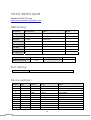
Serial I/O Port
COM ports, RS-232, RS485-2w/4w, can be connected to PLC or other peripheral
devices. Here we view RS-422 the same as RS-485 (4 wire). Please refer to the
appendix in the user manual for correct connection of PLC and touch screen. Besides,
please make sure all DIP switches are on “OFF” (down) position (defaults of the
display).
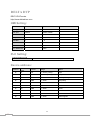
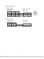
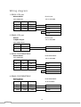
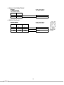
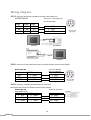
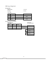
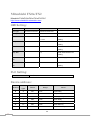
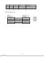
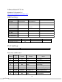
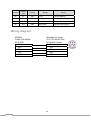
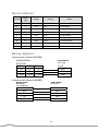
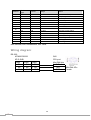
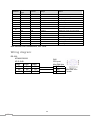
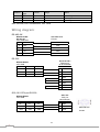
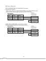
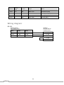
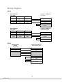
In addition, Weintek provides [MT8-COM1 Multi-Connector cable] and
[MT8-COM3 Multi-Connector cable] to expand a COM port to multiple independent
COM ports so that the efficiency of the operation will be improved. Please refer to the
connection illustration in the manual.
6
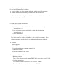
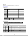
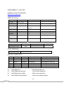
3. MT8000 System Settings
Before first operating MT8000, users have to complete every system setting. After the
setup, use EB80000 editing software to develop a personal operation interface.
The following illustrates every system setting respectively.
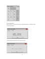
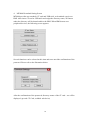
(1)System Reset
Each HMI is equipped with a set of reset button and DIP switch. When using Dip
switch to change different modes, corresponding functions will be triggered. (Please
refer to related chapters.)
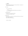
If losing or forgetting system passwords, users can set Dip Switch 1 to “ON” position,
the rest of Dips remain on “OFF” position and then reboot MT8000.
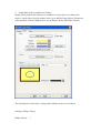
Under this situation, MT8000 will jump to Touch Adjust (Touch screen calibration)
mode. After calibration, the pop-up window appears as the illustration below. Users
will be inquired if restoring the system password to the default value.
When “YES” is chosen, another pop-up dialog appears as below. Users will be
confirmed again if restoring the system password to the default value and will be
7
asked to input “YES”. Then click OK. (The default password is 111111. However,
other passwords, including download and upload password, have to be reset.)
Note: When the reset action is be taken, projects and saved data in the HMI will all be
cleared.
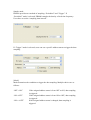
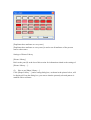
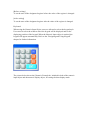
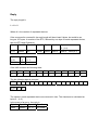
(2) Tool bar
After activating the HMI, users can set the system by using the tool bar at the bottom
of the screen. Normally, tool bar is hidden automatically. Only touch the target at the
corner of the right-bottom will the tool bar pop up.
8
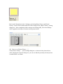
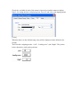
Large Keyboard
Use large keyboard to input the text information.
Small Keyboard
Use small keyboard to input the numerical information.
9
System Information
Network: Display Network information, including IP address of HMI and other
network information.
Version: Display information of the system version.
10
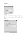
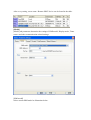
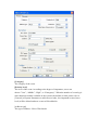
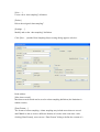
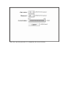
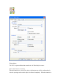
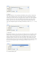
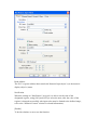
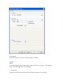
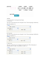
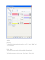
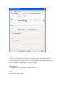
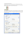
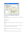
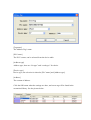
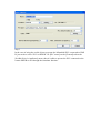
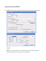
System Setting
Setting or modify system parameters. Password has to be confirmed in view of
security.
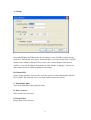
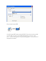
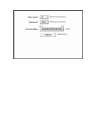
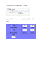
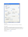
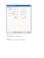
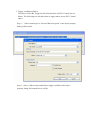
a. Network
Projects can be downloaded to MT8000 via Ethernet so that the IP address of
operation target (HMI) must be correctly set. If “Auto Get IP Address” is selected, IP
address will be automatically assigned from local DHCP network. While if “IP
address get from below” is selected, IP address and other network information have to
be input.
11
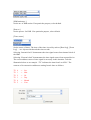
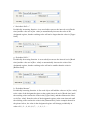
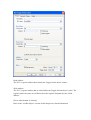
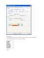
b. Time/Date
System time/date will display at the corner of the bottom-right after the adjustment.
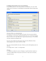
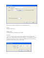
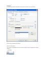
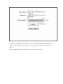
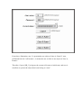
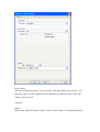
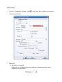
c. Security
Providing stricter security protection for the MT8000. The default of the password is
111111.
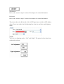
12
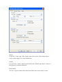
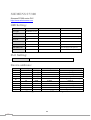
Local Password
Password to enter the system
Upload Password
Password to upload the project
Download Password
Password to download the project
Reserved Password
Password reserved for further usage
Password confirmation:
13
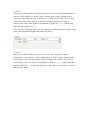
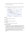
d. History
The tab can clear the historical data in the HIM: Recipe, Event log and Data log.
e. Backlight
Using the rolling bottom on the screen to adjust the brightness of LCD.
14
f. CF Card Stat
When HMI detects other new device, this function will be enabled.
15
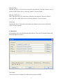
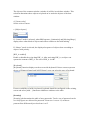
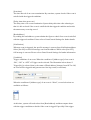
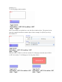
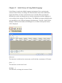
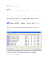
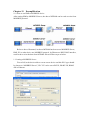
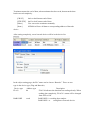
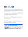
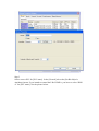
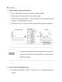
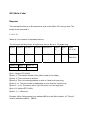
4. MT8000 Download Setting Screen
MT8000 provides two methods: CF card and USB stick, to download a project to
HMI. After insert CF card or USB stick and assign the directory name, all context
under the directory will be downloaded to the HMI. When HMI detects new
peripheral devices, the following screen appears:
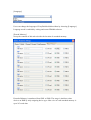
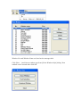
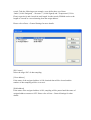
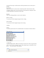
Several functions can be selected at this time and some need the confirmation of the
password. Please refer to the illustration below:
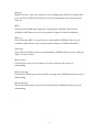
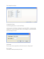
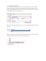
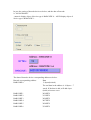
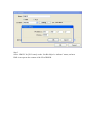
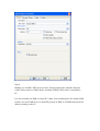
After the confirmation of the password, directory names of the CF card…etc will be
displayed. (pccard: CF Card ; usbdisk: usb device)
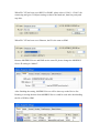
16
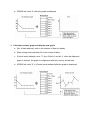
Select the download path and click OK for downloading.
Note: Data to be downloaded will be created from [Build Download Data for CF/USB
Disk] of Project Manager.
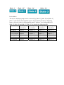
17
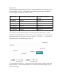
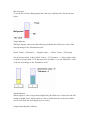
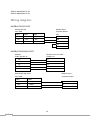
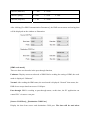
Generally speaking, Project Manager divides the downloaded files into two
directories:
MT8000
store projects
History
The directory will be created when download the historical data.
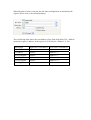
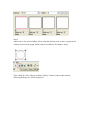
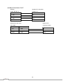
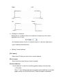
In other words, if location of the saved file as below,
the data structure will as follows:
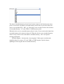
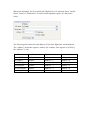
The most upper path should be selected when downloading. In other words, take the
structure above as an example, download must be selected but mt8000 or history is
invalid.
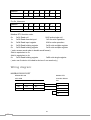
Take the illustration below as another example, usb disk only saves mt8000 directory
but not includes history. In this case, users must choose device-0 to correctly
download the file.
18
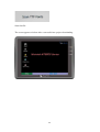
In the process of downloading, screens of HMI change in order:
Stop the current project
Start to download a new project
Activate the new project
19
Scan font file
The screen appears as below after a successful new project downloading.
20
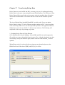
Chapter 2
Project Manager Operations
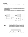
Introduction
Project Manager integrates every available function of the EB8000. Each function
will be introduced in this chapter.
1
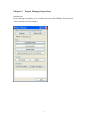
A .Settings
Operating MT8000 by Ethernet needs to designate correct IP address and necessary
password. “Download” and “Reset” functions share a set of password while “Upload”
function uses another password. Please refer to the related chapters about how to
modify or view the IP address and password. After change “Language”, please exit
and restart software to enable language mode change.
B. Reboot HMI
Under certain situation, users need to reset the system, such as updating the internal
files of HMI. This function can be executed without restart the system.
C. EasyBuilder 8000
Activate EasyBuilder 8000 graphical editor.
D. EasyConverter
Data record conversion tool
E. Recipe Editor
Recipe data conversion tool
2
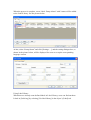
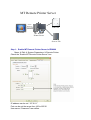
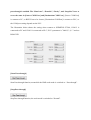
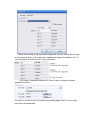
F. Building Download Data from CF Card/USB Stick
Except Ethernet, data also can be downloaded to the MT8000 by CF card or USB
memory stick. The function is for building the download data and the settings shows
as below.
[Select the folder to save download data]
Press [Browse] to search for and assign the file path (or directory name) and then
press [Build] to set all contexts of the downloaded data. Users can directly designate
the save location in CF card/ USB stick or copy the entire directory to CF card/USB
stick after completely building the data.
Insert CF card or USB stick and assign the name of the file, EB8000 will start
downloading the whole content of the file to HMI.
Note: Save location should be the name of directory and avoid designating only root
directory.
For example, both c:\” and f:\\” are illegal names.
[Project]
Use EB8000 to configure the context of display (*.mtp file) and then compile it to
*xob file for HMI terminal. The desired *xob file for CF card can be selected by
using this function.
3
[Recipe (RW)]
RW Recipe file for CF card can be selected by this function. The max effective size of
the file is 64K. Please refer to “Receipt Transfer” for more details.
[Recipe A (RW_A)]
RW_A Recipe file for CF card can be selected by this function. The max effective
size of the file is 64K. Please refer to “Receipt Transfer” for more details.
[Data log]
Data log file for CF card can be selected by this function. Please refer to “data log
object” for more details.
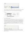
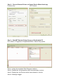
G. Download
Downloading files to the MT8000 through Ethernet. Press the [Download] button and
the dialog appears as below:
[Firmware]
Check [Firmware] to update all of the kernel programs of HMI.
4
[Project]
EB8000 are able to have the content of screen configuration (MTP file) compiled and
get *.xob file for MT8000.The desired *.xob file downloaded to the terminal can be
selected.
[RW]
Select the desired RW recipe data to be downloaded to MT8000. The max size
available is 64K Please refer to [recipe transfer] chapter for further information.
[RW_A]
Select the desired RW_A recipe data to be downloaded to MT8000. The max size
available is 64K. Please refer to [recipe transfer] chapter for further information.
[Data log]
Select the desired data log file to be downloaded to MT8000. Please refer to “Data log
object” for more details.
[Reset recipe]
Check [Reset recipe] to set all figures of recipe to 0 before the process of
downloading.
[Reset event log]
Check [Reset Event log] to clear all of the event log files in HMI before the process of
downloading.
[Reset data log]
Check [Reset data log] to clear all of the data log files in HMI before the process of
downloading.
5
H.Upload
Uploading files to MT8000 by Ethernet and the dialog box shows as below:
[Project]
Select *.xob save location after uploading.
[RW]
Select RW save location after uploading.
[RW_A]
Select RW_A save location after uploading.
I. On-line Simulation/Off-line Simulation
Execute On-line/Off-line Simulation. Select the source of *.xob file before executing
the function as follows:
6
7
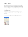
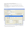
Chapter 3
How to Create a Simple Object
The following takes MITSUBISHI PLC as an example to illustrate how to create a
simple project. First of all, click [New] icon on the toolbar to create a new blank
project as below:
Select HMI Model and Display mode and then click OK.
Except correctly setting the system parameters, click [New…] function on Device
Table to add a new device. The settings are as below:
1
Device “MISUBISHI FX0n” is added to the Device Table after click OK.
If a toggle switch would like to be added, click the object buttons showed as follow.
2
New Toggle Switch Object dialog appears as the illustration. After correct settings of
each property, click OK and put the object to the desired place.
3
Finished window 10 is as below and a simple project is completed.
After the file is saved, users select [Compile] function icon to examine if the screen
configuration is correct.
If the compiling result shows as below which means no error exists, then click the
icon to execute the Off-line Simulation.
4
The following screen is the screen after executing the off-line simulation:
If On-line Simulation needs to be done, click the icon for processing after connecting
the device.
5
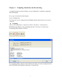
Chapter 4
Compiling, Simulation and Downloading
A complete design procedure includes: screen configuration, compiling, simulating
and downloading.
Every step is introduced in this chapter.
Screen Configuration
Varied screens can be configured by the EB8000 and the edited context is saved as a
*.mtp file.
z Compiling
After screen configuration (*.mtp file), transfer *.mtp file to *.xob format for
MT8000 downloading by using compiling function. Click icon on tool bar and
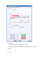
[Compiling] dialog appears as below:
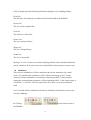
In [Compiling] dialog, [Project name] indicates the name of current configuration file
while [XOB file name] indicates the name of compiled file.
1
Click [Compile] and the following information displays on [Compiling] dialog:
Font files
The font files for displayed text which will be downloaded to the MT8000.
Object size
The size of the compiled file.
Font size
The total size of font files.
Picture size
The size of picture library.
Shape size
The size of shape library.
Sound size
The size of sound file.
Message “0 error” means a successful compiling and then other simulation functions
can be continued. If an error exists, users should follow instructions to correct errors.
z Simulation
There are two simulations: Off-line simulation & On-line simulation. By virtual
device, PC simulates the operations of PLC without connecting to PLC. On the
contrary, On-line simulation is executed by connecting with PLC and accurately
setting the communication parameters. When simulating on PC, if the control target is
a local PLC (i.e. the PLC directly connected to PC), there’s a 10 mins simulative
limit.
Users can find Off-line simulation and On-line simulation functions from two ways:
a. Project Manager
b. Clicking
the EB8000.
,
icons from tool bar of
2
z Downloading
After the completion of the simulation and the confirmation of the screen
configuration, next step is to download *.xob file to MT8000. Downloading *.xob file
can be done by:
[Download] function from Project Manager. Please refer to” Project Manager” related
chapters.
Click
appears as below:
icon from tool bar of the EB8000 and [Download] dialog
[Download] dialog settings:
[HMI IP]
Assign the download target IP
[Password]
Input password. Please refer to the “hardware setting” related chapter.
3
[Reset recipe]
If the function is selected, all recipe figures will be set to 0 before downloading.
[Reset event log]
If the function is selected, all event log files saved in the MT8000 will be cleared
before downloading.
[Reset data log]
If the function is selected, all data log files saved in the MT8000 will be cleared
before downloading.
[Reboot HMI after download]
If the function is selected, MT8000 reboots after downloading is done.
Click [Download] to execute downloading operation. Downloaded files will display
on the message dialog.
4
Chapter 5
System Parameters
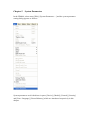
In the EB8000, select menu [Edit] / [System Parameters…] and the system parameter
setting dialog appears as follows:
System parameters are divided into six parts: [Device], [Model], [General], [Security]
and [Font / Language], [Extend Memory] which are introduced respectively in this
chapter.
[Device]
[Device] parameters determine all of the characteristics of each device controlled by a
HMI. These devices include PLC, remote HMI and PC. When open a new *.mtp file,
a default device: “Local HMI” is in the table. “Local HMI” is used to identify current
HMI .Each *.mtp should at least include a “Local HMI” device.
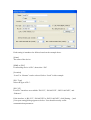
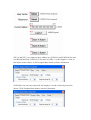
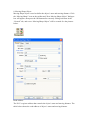
Click [Settings…] to open [Local HMI] dialog box. From the illustration below, the
property of local HMI is “HMI” and the location is “Local”.
The procedure to create a new device:
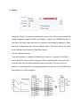
How to control a local PLC
So-called “local PLC” means a PLC is directly connected to local HMI. To control a
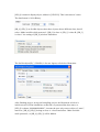
local PLC should add this type of device. Click [New…] and the following [Device
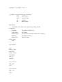
Properties] dialog appears. Correctly fill in all of the properties as required.
Each setting is introduced as follows based on the example above.
[Name]
The name of the device.
[HMI] or [PLC]
If connecting device is PLC, then select “PLC
[Location]
“Local” or “Remote” can be selected. Select “Local” in this example.
[PLC Type]
Select the type of PLC.
[PLC I/F]
Four PLC interfaces are available:”RS-232”, “RS-485 2W”, “RS232-485 4W”, and
“Ethernet”.
If the interface is “RS-232”, “RS-485 2W”or “RS232-485 4W”, click [Setting…] and
[Com port setting] dialog appears as below. User should correctly set the
communication parameters.
If the interface is “Ethernet”, click [Setting…] and then [IP Address Setting] dialog
appears. Users should correctly set IP address and Port No. of the PLC.
[PLC default station no.]
Number of PLC station.
[Interval of block pack (words)]
If the interval of different read addresses of different commands is less than this value,
these commands can be combined to one command. If this value is set to 0, the
combination function will be cancelled.
For example, if the value is set to 5, when read out a word from LW3 and read
out 2 words from LW6 respectively (i.e. read out the contents of LW6 and LW7),
because the interval of addresses between LW3 and LW6 is smaller than 5, these two
commands can be combined to one. The content of combined command becomes 5
consecutive words from LW3 (read out from LW3~LW7). Note: Max. combined
command can’t be more than Max. read-command size (words).
[Max. read-command size (words)]
The Max. data size to be read out from device at one time. Unit: word.
[Max. write-in size (words)]
The Max. data size to be written in to device at one time. Unit: word.
By changing the content of “devicetype.def” under C:\\ EB8000 path to modify
the default of [Max. read-command size (words)] and [Max. write-in size (words)];
Please note that the values have to be accord with the features of devices. Improper
modification will result in communication failure.
After every setting, a new name “Local PLC” device can be found on the table.
How to control a remote PLC
So-called “remote PLC” means a PLC is directly connected to a remote HMI. To
control a remote PLC should add this type of device. Click [New…] and the
following [Device Properties] dialog appears. Correctly fill in all of the properties as
required.
Each setting is introduced as follows based on the example above.
[Name]
The name of the device.
[HMI] or PLC]
If connecting device is PLC, then select “PLC”
[Location]
“Local” or “Remote” can be selected. Select “Remote” in this case and set the
address of the remote HMI. Select [Location]/ [Setting…] to set the IP address of the
remote HMI.
[PLC Type]
Select the type of PLC
[PLC I/F]
The type of interface for remote PLC. If COM port is used by remote PLC,
interface ”RS-232”, “RS-485 2W” or “RS232-485 4W” can be selected.
[PLC default station no.]
The No. of PLC station.
[COM]
The COM port used by a remote PLC. The parameters should be correctly set.
After every setting, a new name “Remote PLC” device can be found in the table.
Select assigned device from the table to operate the specific content of PLC address.
How to control a remote HMI
So-called “remote HMI” means a non-local HMI. PC also can be viewed as one kind
of remote HMI. To control a remote HMI should add this type of device. Click
[New…] and the following [Device Properties] dialog appears. Correctly fill in all of
the properties as required.
Each setting is introduced as follows based on the example above.
[Name]
The name of the device
[HMI] or [PLC]
If connecting device is HMI, then select “HMI”
[Location]
“Local” or “Remote” can be selected. Select “Remote” in this case and set the
address of the remote HMI. Select [Location]/ [Setting…] to set IP address of remote
HMI and correct [Port no.]. Port no. of the remote HMI can be found from [System
parameters]/[Model] in the *.mtp of remote HMI.
After every setting, a new name “Remote HMI” device can be found in the table.
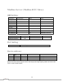
[Model]
[Model] tab parameters determine the settings of HMI model, Display mode, Timer
source and other communication related settings.
[HMI model]
Select current HMI model as illustration below.
[HMI station no.]
Set the no. of HMI station. If no particular purpose, select default.
[Port no.]
Set the port no. for HMI. If no particular purpose, select default.
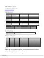
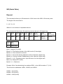
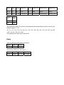
[Time source]
Set the source of timer. The time of the timer is used by such as [Data Log], [Event
Log] ….etc. objects which needs the time records.
Selecting “Internal clock” demonstrates the time signal comes from internal clock of
the HMI.
Selecting “External clock” demonstrates the time signal comes from external device.
The correct address source of time signal is necessary in this situation. Take the
illustration below as an example. “TV” indicates the time from Local PLC. The
contexts of 6 consecutives addresses starting from 0 show as follows:
TV
TV
TV
TV
TV
TV
0
1
2
3
4
5
->
->
->
->
->
->
Sec.
Min.
Hr.
Day
Month
Year
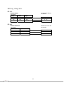
[General]
[General] tab parameters determine all properties related to screen operations.
Each setting is introduced as follows:
[Fast selection button]
The settings of all attributes for Fast selection window which is designated as window
number 3.
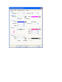
a. [Attribute]
Enable or disable a Fast Selection window. After selecting “Enable”, click [Setting…]
to set the personality attributes of the buttons including color and text.
b. [Position]
Select the location of the Fast select button. If “Left” is chosen, the button will show
up at the corner of the left-bottom. If “Right” is chosen, the button will show up at the
corner of the right-bottom.
[Screen saver]
a. [Back light saver]
If the untouched duration of screen is equal to this value, back light shuts off. The
setting unit is minute. Back light is triggered once the screen is touched.
b. [Screen saver]
If the untouched duration of screen is equal to this value, the current screen
automatically switches to the assigned [Saver window no.].The setting unit is minute.
If “none” value is selected, screen saver function is disabled.
c. [Saver window no.]
When executing screen saver function, [Saver window no.] designates the screen to be
switched.
[Option]
a. [Startup window no.]
Select the window after HMI is started up.
b. [Extra no. of event]
The default of number of events in the system is 1000 in total. If users would like to
add more records, the setting value can be modified up to 10000.
c. [Common window]
The objects of the common window (window 4) will be in each base window. This
selection determines these objects are placed on or under the objects of the base
window.
d. [Cursor color]
Set the color of cursor.
e. [Object layout]
If “Control” mode is selected, when HMI operates, [Animation] and [Moving Shape]
display above other kinds of objects and with no relation to the built ranking.
If “Nature” mode is selected, the displayed sequence of objects show according to
objects’ built priority.
[RW_A enabled]
Enable or disable the recipe data RW_A. After activating RW_A, an object can
operate the content of RW_A .The size of RW_A is 64K.
[Keyboard]
[Keyboard] function displays on the screen with keyboard. If these screens represent
the use of [Numeric Input] and [ASCII Input], users can select the type of keyboard.
If users would like to build a keyboard, keyboard should be configured on the existing
screen and select [Add…] function to add these windows to the table.
[Security]
[Security] tab determines the table of user passwords. Twelve sets of password can be
set. Only figures are allowed for password. From user 1 to user 12, each user
password has different object class from A to F.
In the project, all object has been set to operate different class from None and class A
to class F.
When setting user 1 as below, this user only can use None, A, C, E. Detail setting
please refer “Chapter 10 Object’s Security Guard”.
[Font / Language]
[Font / Language] tab determines the font of non-ASCII strings.
[Fonts for non-ASCII strings]
This table lists the fonts for non-ASCII strings. If users use the fonts of non-ASCII
strings without choosing the font from [Fonts for non-ascii strings] table, EB8000 will
automatically pick up these fonts.
Users can test which non-ASCII strings in the WINDOWS can be used in MT8000
and add them to [Fonts for non-ASCII strings] table.
[Language]
Users can change the language of Easy/Builder 8000 toolbars by choosing [Language].
Language mode is enabled by exiting and restart EB8000 software.
[Extend Memory]
Set up the contents of this tab to decide the location of extended memory.
Extended Memory is numbered from EM1 to EM9. The usage is similar to other
devices on HMI by only assigning device type. Max. size of each extended memory is
up to 2G word data.
The data in extended memory doesn’t lose because of power off which means when
power on next time, the data in extended memory will restore to previous status, the
same as receipt data (EW、RW _A). Especially, users are able to choose the location
of extended memory—CF card, USB1 or USB2 memory stick.
When the device set as extended memory doesn’t exist, if users read out the data from
extended memory, the content is always 0; When the device set as extended memory
doesn’t exist, if users write in the data to extended memory, “PLC no response”
message will appear.
MT8000 support “ hot insertion , hot swapping”: Under power continuously
supplied, plug in or remove CF card, USB1 or USB2 anytime. By this feature,
updating or retrieving the data in extended memory.
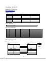
Chapter 6
Window Operations
1. Screen types
A screen is composed of basic element—Window. Users are able to configure 1997
windows or screens. According to function and usage, there are 4 types of windows in
the EB8000.
(1) Base Window
(2) Common Window
(3) Fast Selection
(4) System Message Window
For example as below:
(1) Base Window
Base window is a common type of window.
Except for primary screen, it is used on:
a. Foundation base: used as a background of other windows.
b. Keyboard window.
c. Pop-up window for function key objects.
d. Pop-up window for direct and indirect windows
e. Screen saver
The illustration below is the screen of startup which uses base window.
(2) Common Window
Window 4 is the default of common window. Objects on this window will display on
other windows so that users always place the shared objects on common window.
When system operates, [Change common window] mode of the function key can be
used to change the source of common window. For example, change the common
window from window 4 to window 20.
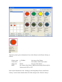
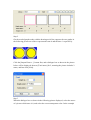
(3) Fast selection window
Window 3 is defined as Fast Selection Window. This window can co-exist with base
window. Therefore, generally speaking, it is used by the common-used operation
buttons as the picture below:
When using Fast Selection Window, except creating window 3 first, each function of
Fast Selection button should be set. The [Startup] on the picture above is the Fast
Selection button which is used to change the appearance and the disappearance of the
Fast Selection. Every setting of the Fast Selection button is in System Parameter
Settings. Please refer to the illustration below.
Except switching the appearance and the disappearance of the Fast Selection by Fast
Selection button, system register also provides the following addresses for users who
are able to control Fast Selection and Fast Selection button by the operation of the
values in the address. Please refer to “system register” for further introduction.
[LB9013] Enable/Disable Fast Selection
[LB9014] Enable/Disable Task button
[LB9015] Enable/Disable Fast Selection/ Task button
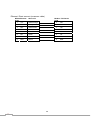
(4) System Message Window
Window 5, Window 6 and Window 7 are the defaults of system message window.
Among them, Window 5 is the “PLC Response” message window. When the signal of
PLC is unreceivable, the message window will pop up automatically. Window 6 is the
message window for “HMI Connection”. When connection of remote HMI fails, the
message window will pop up automatically.
Window 7 is set for “Password Restriction” message window. If users don’t have
enough authority to operate the object, window 7 will pop up according to the setting
contents.
2. Creating, deleting and setting of a window
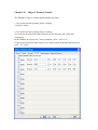
The picture below displays the window information of the EB8000. The following
section introduces how to create and set these windows.
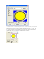
(1) Creating a window
There are two ways to create a window: a) selecting desired window number on the
window tree and right click Select [New] on the message dialog and click confirm
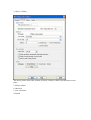
after the completion of all settings. Please refer to the example below:
[Name]
The name of the window
[Window no.]
The No. of the window, from 3 to 1999.
Size
The [Width] and [Height] of the window.
Frame
[Width]
The [Width] of the frame.
[Color]
The color of the frame.
Background
[Color]
The color of the background.
[Pattern]
The design of the background.
[Pattern color]
The color of the design.
[Filled]
The Filled option determines if the window’s background color is shown or not
during project design.
Underlay window
[Bottom], [Middle], [Top]
Up to three windows can be specified as underlay windows for each base window,
from [Bottom] to [Top]. The objects on the background window are displayed on base
window in order.
Popup window
[X], [Y]
Base window can also be used as pop-up window. [X] and [Y] set the pop-up location
of the base window.
[Monopoly]
If the option is checked, when a base window is used as pop-up window and appears,
users are not allowed to operate other windows before the base window is closed. If a
base window is used as a keyboard window,” Monopoly “property is automatically
possessed by the window.
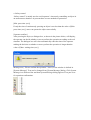
Another way to create a window is select [Open Window] from menu and [Open
Window] dialog appears. Please refer to the illustration below.
Window No. and Window Name are listed on the message table.
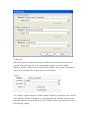
Click [New…] and choose window type from [Select Window Style] dialog. New
window can be created after click OK.
(2) Window Settings
EB8000 provides two methods to modify window attributes:
a) Right click on the assigned window from window tree and select [Settings] to
change the window properties.
b) Select [Open Window] from menu and [Open Window] dialog appears. Select
[Settings] to change the window properties.
(3) Open, close and delete a window
To open an existing window, except double clicking the window No. from window
tree, another way is right click the assigned window from the window tree and choose
[Open] to open the window.
It’s the same operation process to close or delete an existing window but please note
that the window has to remain in close status when deleting a window.
Chapter 7
Event Log
“ Event log” is used to identify the content of an event and the conditions triggering
this event. In addition, the triggered event (sometimes it is called alarm) and the
processing procedure of the event can be saved to the designate location through the
EB8000 as eventlogyyyymmdd.evt format where yyyymmdd indicates the creating
time and is set by the system. For example, a file name of event,
logeventlog20061127.evt, means the file is created on Nov. 27, 2006.
1. Creating a new data log
Accompanied with alarm bar, alarm display and event display, users are able to
clearly understand the life cycle of whole event from happening, waiting, processing
to alarm disappearing. Before using these objects, the content of an event has to be
identified first.
Click the [Alarm(Event Log)] icon, and [Event Log] dialog appears as below:
[Category]
The EB8000 provides category function and divides an event into 0~255
classifications. Alarm Bar、Alarm Display and Event Display can limit the displayed
classifications.
[Catalog] selection determines the event catalog of current event. New added event
type is determined by this function.
The [2] of 0[2] in the above illustration demonstrates two existing identified events in
the classification 0.
History files
History files determine the save location of an event log. However, when users
simulate on PC, files will be saved on the eventlog subdirectory, the same the
subdirectory of EasyBuilder8000.exe.
[Save to HMI memory]
Record the event log to MT8000.
[Save to CF card]
Save the event log to CF card.
[Save to USB disk 1]
Save the event log to USB disk 1. The USB disk numbering rule is: the disk inserted
to the USB interface in the first place is numbered 1, next is numbered 2 and the last
is numbered 3. There’s no relation with the interface location.
[Save to USB disk 2]
Save the event log to USB disk 2.
[New …]
Create a new event.
[Delete]
Delete a specific event.
[Settings …]
Modify the definition of a specific event.
After clicking [New…], [Event Log] dialog appears with two tabs and [General] tab
shows as below:
[Category]
The category of the event.
[Priority level]
The level of the event: According to the degree of importance, users can
choose ”Low”, “Middle”, “High”, or “Emergency”. When the number of event log is
more than max number available in the system (the default is 1000, please refer to
[General] of System Parameters to add extra records), less important events (lower
level) will be deleted and new events will be added in.
[Address type]
The type of address—Bit or Word mode.
[Scan time]
The time interval of an event examination. By scan time, system checks if the event is
satisfied with the triggered conditions.
[Delay time when power on]
The delay time of an event examination. System delays this time after rebooting so
that it’s able to check if the event is satisfied with the triggered condition and avoids
the unnecessary event log record.
[Read address]
By reading the read address, system obtains the figure to check if an event is satisfied
with the triggered condition. Please refer to Parts/General Settings for further details.
[Notification]
When an event is triggered, the specific message is sent out from Notification address.
Select [Set ON] to send ON message out from the address. While select [Set OFF],
Off message is sent out. Please refer to Parts/General Settings for further information.
[Condition]
Trigger conditions of an event. When the condition of [Address type] of an event is
“Bit”, “ON” or “OFF” of Trigger can be selected. The illustration below shows if
Trigger[On] is selected, that is, the status of [Read address] changes from OFF to ON,
an event will be triggered and generate an event log record (or an alarm).
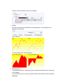
When the condition of [Address type] of an event is “Word”, several selections are
available as follows:
At this time, system will read values from [Read address] and then compare them
with the trigger conditions to decide if the event is trigged. Especially if the trigger
condition is ”==” or <>”, [In tolerance] and [Out tolerance] can be set where [In
tolerance] is used for trigger condition and [In tolerance] is used for system’s normal
condition.
From the example above, it indicates that if the value of [Read address] is bigger or
equal to 29(=30-1) or smaller or equal to 31(=30+1), the event will be triggered.
After the event is triggered, only when the value of [Read address] is bigger than
32( =30+2) or smaller than 28(=30-2) will the system return to the normal condition.
From the example above, it shows that system is under normal condition only when
the value of [Read address] is bigger or equal to 28(=30-2) and smaller or equal to
32(=30+2).
When the event is triggered, system returns to normal condition only when the value
of [Read address] is bigger or equal to 29(=30-1) and smaller than 31(=30+1).
Please refer to the picture below for the settings of [Message] tab.
Text
[Content]
The text context showed on alarm bar、alarm display and event display. Please refer
to “Parts/General settings” for more information.
[Write value for event display]
When event display of the event is touched, the write value is sent out to the assigned
address. Please refer to event display of parts chapter.
[Sound]
The warning alarm can be selected when an event is triggered.
Click “Sound Library” to choose warning sound, and click “Play” to check the sound.
After the completion of each setting, a new event definition can be added as below:
Chapter 8
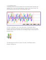
Data Sampling
“Data Sampling” identifies the method of data sampling, including sampling time and
sampling location. Besides, EB8000 saves the obtained sample data as
filenameyyyymmdd.dtl format to the assigned location where filename is defined by
users and yyyymmdd is the built time setting by system. For example, if the file name
is presser20061127.evt, it means the file saves the data sampled on Nov. 27, 2006.
1. Create a new defined of data sampling
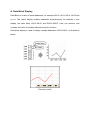
Before using Trend display to view the content of data sampling, the method of data
sampling has to be defined. Click [Data Sampling] from toolbar and then Data
Sampling Object dialog appears as below:
[New …]
Create a new “data sampling” definition.
[Delete]
Delete the assigned “data sampling”.
[Settings …]
Modify and set the “data sampling” definition
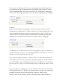
Click [New…] and the Data Sampling Object setting dialog appears as below:
Read address
[Max. data records]
Max data records which can be saved to a data sampling definition (the limitation is
86400 records).
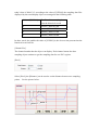
[Data Format …]
The format of a data sampling: A data sampling may include more than one record
and EB8000 is able to retrieve different formats of records at the same time. After
clicking [Data Format], users can use “Data Format” dialog to define the content of a
record. Take the following as an example, users define three set of data:
“Index”(16-bit Unsigned)、“Pressure 1”(16-bit Signed) and “Temperature”(32-bit
Float) respectively and 4 words in total length. In other words, EB8000 retrieves the
length of 4 words as a record starting from the assign address.
Please refer to Parts—General Settings for more details.
[PLC name]
Select the target PLC of data sampling.
[Clear address]
If the status of the assigned address is ON, obtained data will be cleared and the
number of data sampling will be set to zero.
[Hold address]
If the status of the assigned address is ON, sampling will be paused until the status of
assigned address returns to OFF. Please refer to Parts—General Settings for other
details.
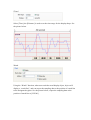
Sample mode
EB8000 provides two method of sampling: “Periodical” and “Trigger”. If
“Periodical” mode is selected, EB8000 samples the data by a fixed time frequency.
Users have to set the “sampling time interval”.
If “Trigger” mode is selected, users can use a specific address status to trigger the data
sampling.
[Mode]
Mode determines the condition to trigger the data sampling. Multiple choices are as
follows:
“OFF->ON”
“ON->OFF”
“ON<->OFF”
If the assigned address status is from OFF to ON, data sampling
is triggered.
If the assigned address status is from ON to OFF, data sampling
is triggered.
If the assigned address status is changed, data sampling is
triggered.
Please refer to Parts—General Settings for more details.
[Auto stop]
When the number of obtained data is equal to [Max. data records], if the Auto stop
option is selected, data sampling will stop automatically or EB8000 will delete old
record and add in new data.
History files
History files assigns the save location of data sampling record. But when users do the
simulation on PC, data is saved to datalog subdirectory, the same subdirectory as
EasyBuilder 8000.exe.
[Save to machine]
Save the sampling to MT8000 display.
[Save to CF card]
Save the sampling to CF card.
[Save to USB stick 1]
Save the sampling to USB stick 1. The USB stick numbering rule is: the stick inserted
to the USB interface in the first place is numbered 1, next is numbered 2 and the last
is numbered 3. There’s no relation with the interface position.
[Save to USB stick 2]
Save the sampling to USB stick 2.
[File name]
Set the file name of sampling and then EB8000 adds the time mark following the file
name. For example, if users set the file name as ”pressure”, the real file name saved
will become pressure20061127.dbl where 20061127 stands for the built date.
Chapter 9
Object’s General Attributes
The contents of object’s general attribute setting include:
1. Selecting the Connection PLC Device
2. Setting the Reading and Writing Address
3. Using Shape Library and Picture Library
4. Setting Text Content
5. Adjusting Profile Size
1. Selecting the Connection PLC Device
When using some objects, selection of the connection PLC device is required. See the
picture below, [PLC name] is to indicate the name of the connection PLC device. The
picture shows that there are two PLC devices available for selection: “Local HMI”
and “Allen-Brandley DF1.” These listed available PLC devices are sourced from
“device table” in “system parameters.”
2.
Setting the Reading and Writing Address
The above picture shows that the following items are contained in Reading and
Writing Address settings:
[Device type]
In selection of device types, when the connection PLC device is different, there will
be different device types for selection.
[Address]
Setting the reading and writing address.
[System tag]
Address tag includes “system tag” and “user-defined tag.” System tag, including bit
address system tag and word address system tag, is to reserve the addresses of
particular purposes for the system. When selecting “system tag,” in addition to that
[Device type] will show the content of “system tag,” [Address] will indicate the
selected system tag. Refer to the picture below.
The following pictures show partial contents of bit address system tag and word
address system tag respectively, and for further information, please refer to the
illustrations in the “label library” section.
bit address system tag
word address system tag
[Index register]
Refer to the illustrations in “index register” section for information on if it is
necessary to select “index register” or not.
Selecting Numeric Type
The EB8000 supports the following listed numeric types. It is necessary to select the
proper numeric type, especially when using address tag.
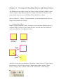
3. Using Shape Library and Picture Library
Shape Library and Picture Library are available for some objects to enhance the
object’s visual effects. See the picture below, go to the Bit Lamp Object’s Properties
menu and then click the [Shape] tab to set up Shape Library and Picture Library.
The descriptions of each item’s setting on the [Shape] menu are as follows:
Settings of Shape Library
[Shape Library …]
Refer to the part (I) at the last of this section for information related to the settings of
[Shape Library …].
[Use Shape]
Set whether or not to use the functions in Shape Library by selecting [Use Shape] or
not.
[Inner]
Set whether or not to add inner to the Shape by selecting [Inner] or not. When
selecting [Inner] and clicking the color tab, the setting dialog box, as shown in the
picture below, will be displayed to set the inner’s color.
[Frame]
Set whether or not to add a frame to the Pattern by selecting [Frame] or not. When
selecting [Frame] and clicking the color tab, the setting dialog box will be displayed
to set the frame’s color.
[Interior Pattern]
[Interior Pattern] is used to set the color of the interior pattern.
[Pattern Style]
Click [Pattern Style] and a setting dialog box, as shown in the picture below, will be
displayed to set the pattern style.
[Duplicate these attributes to every state]
[Duplicate these attributes to every state] is used to set all attributes of the present
state to other states.
Settings of Picture Library
[Picture Library]
Refer to the part (II) at the last of this section for information related to the settings of
[Picture Library …].
(I)
How to set [Shape Library …]
Click [Shape Library …] and a setting dialog box, as shown in the picture below, will
be displayed. From the dialog box, you can see that the presently selected pattern is
marked with a red frame.
The above picture gives information of one of the Shapes in the Shape Library as
follows:
0: Untitled
State no.: 2
Frame
This indicates the Shape’s name and number in the library.
This indicates the number of the Shape’s states, and in this case, it
shows the Shape possesses two states.
This indicates that the Shape is set with “frame” only.
And the picture below shows that the Shapes is set with “inner” and “frame.”
Refer to the illustrations in the “Setting-up and using Shape Library and Picture
Library” section for the details about all of the settings in the “Shape Library’s setting
dialog box.” After completing all the settings and clicking [OK], the selected Shape
will be applied to the object, as shown in the picture below.
(II) How to set [Picture Library …]
Click [Picture Library …] and a setting dialog box, as shown in the picture below,
will be displayed. From the dialog box, you can see that the presently selected picture
is marked with a red frame.
The above picture gives information of one of the Picture in the Picture Library as
follows:
Picture name
Total states
Image size
BMP
: 0 : PB Red
the name of the Picture
:2
the number of the Picture states
: 30054
the size of the Picture
: the format of the Picture; BMP means bitmap Picture and its
format can be JPG or GIF.
Refer to the illustrations in the “Setting-up and using Shape Library and Picture
Library” section for the details about all of the settings in the “Picture Library’s
setting dialog box.” After completing all the settings and clicking [OK], the selected
Picture will be applied to the object, as shown in the picture below.
4. Setting Text Content
See the picture below, go to the Bit Lamp Object’s Properties menu and then click the
[Label] tab, where you can set the text content that is going to be applied in the object.
Settings in “Attribute”
[Font]
[Font] is used to select the font for the text. The EB8000 supports WINDOWS’s
true-font. See the picture below.
[Color]
[Color] is used to select the font color for the text.
[Size]
[Size] is used to select the font size for the text. The EB8000 supports all the text sizes
shown in the picture below.
[Align]
[Align] is used to define the alignment method of the text input more than one line.
The picture below shows how the lines of the text to be aligned by specifying “Left”
in [Align].
The picture below shows how the lines of the text to be aligned by specifying
“Center” in [Align].
The picture below shows how the lines of the text to be aligned by specifying “Right”
in [Align].
[Blink]
[Blink] is used to define how the text blinks. There are three options in text blinking
setting: specifying “Normal” for non-blinking text, or specifying the blinking speed to
be “1 second” or “500 ms” for blinking text.
[Italic]
[Italic] is used to set whether or not to use italics.
[Underline]
[Underline] is used to set whether or not to underline the text.
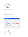
Settings in “Movement”
[Direction]
[Direction] is used to set the direction of the text movement while using the marquee
effect, which is available in a choice of directions shown in the picture below:
[Continuous]
When setting to use the marquee effect, the text in the picture below will be displayed
in two ways:
When not selecting [Continuous], the latter text will emerge only after the former text
disappears completely. See the picture below.
When selecting [Continuous], the text will emerge continuously.
[Speed]
[Speed] is used to set the speed of the text movement.
[Content]
[Content] is used to set the content of the text. If using the Label Library, the content
will be sourced from the Label Library.
[Use label library]
See the picture below, the content of the text will be sourced from the Label Library
by selecting [Use label library].
[Tracking]
When selecting [Tracking], moving the text of some state will also move the text of
other states.
[Duplicate this label to other states]
This function can be used to duplicate the present text content to the other states.
[Label Library …]
Refer to the illustrations in the “Setting-up and using Text and Label Library” section
to view the content of label library.
5. Adjusting Profile Size
See the picture below, go to the Bit Lamp Object’s Properties menu and then click the
[Profile] tab to adjust the position and size of the object.
Settings in “Position”
[Pinned]
Pinning the settings of the position and size of the object by selecting [Pinned], and
the position and size of the object will not be able to be changed.
[X] and [Y] are the coordinates on the top left-hand corner of the object.
Settings in “Size”
[Width]
[Width] is used to adjust the width of the object.
[Height]
[Height] is used to adjust height of the object.
Chapter 10
Object’s Security Guard
The EB8000’s object’s security guard includes two parts:
1. User password and operating object’s setting
2. Object’s Safety
1. User password and operating object’s setting
Users can set the passwords and restrictions in the [Security] tab of [System
parameters]..
In the EB8000, the object has 7 items, including “none”, and “A~F”.
Each group of password must consist of 0-9 digits and the maximum passwords for
users are 12sets.
After user fill in password, EB8000 will be following the security setting to limit the
user to operate objects. For example, when user 1 operating class as below illustration,
this user is permitted to operate “None”, and A, C, E objects.
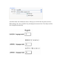
In addition to inputting the passwords to the system reserved [LW9220] register,
which is a double words value, a correct process of password setting requires that
users have to use [LW9219] to appoint the existing user. In [LW9219], it is necessary
to use the digits 1~12 to represent User 1 ~ User 12 respectively.
When MT8000 is operated, user 1 to user 12 can read data of [LW9500] to [LW9522],
totally 24 words.
Users can change passwords even when the MT8000 is in operation. By using the
system reserved register [LB9061], when switching its state from OFF to ON, the
EB8000 will use the data saved in the system reserved registers from [LW9500] to
[LW9522] to update the password table, and the new passwords will be available
immediately. There is something important here that the user’s operation level will
never be changed when the password table is updated.
To switch the current user can use [LW9050] (user logout), when [LW9050] state
from ON to Off; at this time, the user only can operate the object of “class none”.
Otherwise, [LW9222] record current user restrictions, bit0 = 1 means user restriction
is class A; bit1=1 means user restriction is class B and so on.
2. Object’s Safety
The above picture shows the content of Object’s Safety, which is divided into several
parts:
a. Safety control
b. Interlock
c. user restriction
d. Sound
a. Safety control
“Safety control” is mainly used to avoid operator’s incorrectly controlling an object in
an unawareness situation. At present there are two methods of protection:
[Min. press time (sec)]
If only the time of continuously pressing an object is not less than the value of [Min.
press time (sec)], users can operate the object successfully.
[Operator confirm]
After pressing the object, a dialogue box, as shown in the picture below, will display,
the operator can decide whether or not to perform the operation according to the real
situation. The dialogue box will close automatically when the time of the operator
making the decision on whether or not to perform the operation is longer than the
value of [Max. waiting time (sec)].
Message text ( “Please confirm the operation.” above) in the window is defined in
[System Message]. Text can be changed from [System Message] dialog. Click System
Message icon from tool bar and then System Message dialog appears. First part is set
for operation confirmation.
b. Interlock
When the function is applied to an object, whether or not to allow the object to be
operated will decide the state of the appointed bit address (or called “Enable”
address). ”Enable” address must be in bit address format. The content of the address
can be set in a dialogue box as shown in the picture below.
Fox example, supposed that the “Enable control” function is applied to some “Set Bit”
object and the “Enable” bit address is set to [LB0], then the “Set Bit” object can be
operated when the state of [LB0] is ON. The “Enable control” function also provides
the following settings.
[Enable]
The “Enable control” function can be used by selecting the check box
[Hide when disabled]
When using the “Enable control” function and the state of “Enable” bit address is set
to OFF, the object will be hidden.
c. User restriction
This function can be used to set the object’s operation , deciding which level’s
operator is permitted to operate the object. When “Operator level” is selected
as ”None”, it means the operation is open to the operators of all levels. The following
settings are also available in the function:
[Disable protection permanently after initial activation]
Once the operator’s current operation level conforms to the operation condition of the
object, the system will stop checking the operation level of the object for good. In that
case, even if the current security level is lower than the object’s operation level, it will
not affect the operation of the object.
[Display warning message if access denied]
When the operator’s current security level does not conform to the operation
condition of the object, a warning dialogue box, as shown in the picture below, will
display when pressing the object.
Window 7 is set as alert message for authority security. Users can design the content
of the message.
[Make invisible while protected]
When the operator’s security level does not conform to the operation condition of the
object, the object will be hidden.
d. Sound
Each object can be set to use the buzzer or not individually. The EB8000 also
provides the reserved register [LB9019] as a switch of Buzzer. When the state of
[LB9019] is OFF, the buzzer can be used. When restarting the machine, the EB8000
will use the state of the previous setting.
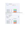
An example for security as below.
First, building a new project, and go to system parameter-> security, and then enable
three users to set different password and class.
User 1 can operate object A, user 2 can operate object A and B, user 3 can operate
object A, B, and C.
Setting objects in Window_10 as below illustration.
[NE_0] and [NE_1] are numeric input, address are [LW9219] and [LW9220] for enter
user ID and password. [LW9219] is for enter user ID(1~12), the length is 1 word, so
this object need to choose 16-bit Unsigned data format, as below illustration.
[LW9220] is for enter user password, the length is 2 words, so this object need to
choose 32-bit Unsigned data format, as below illustration.
[ND_0] is numeric display object, address is [LW9222]. This is shown user’s state.
The data format is 16-bit Binary.
[SB_0]~[SB_2] are Set Bit objects, these three objects choose different class, but all
select “Make invisible while protected“. [SB_0] is class A, [SB_1] is class B, [SB_2]
is class C. the setting of [SB_0] as below illustration.
The Set Bit object(SB_3, LB9050) is for user logout, refer below illustration.
After finishing project, saving and compiling project, the illustration as below is
initial screen in off-line simulation, at this time, no password has been enter, so
[ND_0] is shown “00000000000000”, it means the user only can use object of “none”,
moreover, [SB_0]~[SB_2] belong to class A~ class B and select “Make invisible
while protected“, so [SB_0]~[SB_2] will be hidden.
After User enter the password (111) completely, the screen as below,
The user 1 is permitted to use object of class A, so [SB_0] appeared and allow user to
operate. Now, [LW9222] bit 0 became 1, it means the user is allow to use object of
class A.
Next, user enter the user 3’s password (333), the screen as below,
From above illustration, user 3 is permitted to use object of class A, B and C. now,
[LW9222] bit0~bit 3 all became 1, it means the user is allow to use object of class A,
B and C.
Therefore, if press [SB_3] to logout, the system will return to initial state, and user is
not allow to operate the object that is not belong to “none”.
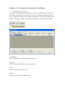
Chapter 11 Index Register
Address Index
The EB8000 provides 16 index registers, and that enables users to enjoy a more
flexible approach to application of the addresses. The addresses of the 16 index
registers are as follows:
INDEX 0
INDEX 1
INDEX 2
INDEX 3
.
.
INDEX 14
INDEX 15
[LW9200] (16-bit)
[LW9201] (16-bit)
[LW9202] (16-bit)
[LW9203] (16-bit)
[LW9214] (16-bit)
[LW9215] (16-bit)
Here is an example to describe how to use the index registers. See the picture below,
the “Read address” will be read as [LB100] while [Address index] is not selected.
But in the picture below, the “Read address” becomes [LB(100 + INDEX3)] while
[Address index] is selected, and INDEX3 represents the data at Index Register 3 or
the [LB9023] address; in other words, if the data at the [LB9023] address is 5, the
“Read address” in the picture below became [LB105].
By making use of the index registers, users can change object’s reading and writing
addresses online without changing the object’s content. For example, in the picture
below, INDEX3 is 0, and that means the data at the [LB9023] address is 0, so to
reading the content of [LB100 + INDEX3] and [LB101 + INDEX3] means to read the
content of [LB100] and [LB101].
At this time, the setting of Object A’s “Read address” is as follows:
And the setting of Object B’s “Read address” is as follows:
And the setting of Object C’s “Read address” is as follows:
If you set INDEX3 to 20, reading the content of [LB100 + INDEX3] and [LB101 +
INDEX3] will mean to read the content of [LB120] and [LB121]. Refer to the picture
below.
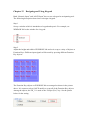
Chapter 12
Designing and Using Keypad
Both “Numeric Input” and “ASCII Input” have to use a keypad as an inputting tool.
The following description shows how to design a keypad.
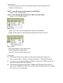
Step 1
Set up a window which is intended as a keypad and open it. For example, set
WINDOW 200 as the window for a keypad.
Step 2
Adjust the height and width of WINDOW 200 and on it set up a variety of objects as
Function Keys. Different input signals will be made by pressing different Function
Key objects.
The Function Key objects on WINDOW 200 are arranged as shown in the picture
above. It is a must to select [ASCII mode] to set up all of the Function Key objects.
Among the objects, the FK_11 is used as the “Escape (Esc)” key. See the picture
below for the setting.
And the FK_12 is used as the “ENTER” key. See the picture below for the setting.
Most of the other Function Keys are used to input numbers or text. For example, the
FK_0 is used to input the number “0”. See the picture below for the setting.
At last, select a proper Picture for each Function Key object, as shown in the picture
below.
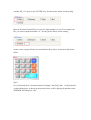
Step 3
Go to [General] tab in “System Parameter Settings” and click [Add…] in [Keyboard],
a setting dialog box, as shown in the picture below, will be displayed, and then select
WINDOW 200 and press “OK”.
As shown in the picture below, a new item: “200.Keyboard” will be added to
[Keyboard] in [General] tab in “System Parameter Settings.”
After completing all the steps described above, when users open the setting window
of “Numeric Input” or “ASCII Input,” “200.Keyboard” can be found to add to
[Window no] in [Keyboard] setting tab, as shown in the picture below. [Popup
Position] can be used to set the displaying position of the keypad, and in this function,
the EB8000 divides the screen into 9 areas. The top left-hand corner of the keypad
will be placed in the top left-hand corner of the selected area.
After selecting “200.Keyboard,” when users press “Numeric Input” or “ASCII Input”
objects, WINDOW 200 will pop up on the MT8000 screen. See the picture below,
clicking the Function Key objects on the created keypad means the same thing of
inputting information by using a physical keyboard.
Chapter 13
Object
This chapter is to illustrate the ways of using and setting all kinds of objects, and
information other than that provided in this chapter can be found in the chapter of
“Object’s General Attributes” chapter.
1. Bit Lamp Object
Bit Lamp object displays the ON and OFF states of a designated bit address. If the bit
state is OFF, the State 0 shape will be displayed. If the bit state is ON, the State 1
shape will be displayed
Click the “bit lamp” icon on the toolbar and the “Bit Lamp Object’s Properties”
dialogue box will appear, then press the OK button after correctly setting each item on
the “General” tab, and a new bit lamp object will be created. See the pictures below.
[Description]
A reference name (not displayed) that you assign to the Bit Lamp.
[PLC name]
Select the PLC that you want to operate.
Read address
The PLC’s register address that controls the Bit Lamp object’s states.
[Invert signal]
Inverse displaying of present states; for example, in fact the present state is “OFF”,
but the object displays the “ON” shape.
Blinking
The settings of blinking effect.
[Mode]
Blinking mode
Description
None
No blinking.
Alternating image on state 0
Enable the shape’s blinking to alternate
between state 0 and state 1 when the device
address is OFF.
Alternating image on state 1
Enable the shape’s blinking to alternate
between state 0 and state 1 when the device
address is ON.
Blinking on state 0
The shape of state 0 blinks when the device
address is OFF.
Blinking on state 1
The shape of state 1 blinks when the device
address is ON.
When select the blinking effect, [Blinking time] is used to set the frequency of
blinking.
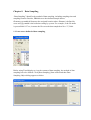
2. Word Lamp Object
A Word Lamp object changes the state and shows the corresponding shape according
to the value in the designated word address. (The EB8000 supports a maximum of
256 states)
Click the “Word lamp” icon on the toolbar and the “Word Lamp Object’s Properties”
dialogue box will appear, then press the OK button after correctly setting each item on
the “General” tab, and a new word lamp object will be created. See the pictures
below.
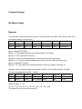
[Mode]
Word lamp object offers the following three modes for selection:
“Value” display mode
Directly using the result of the value of register subtracting the setting number of
[Offset] as the object’s current state. For example, add a new word lamp object, and
the object’s [Offset] number is 3. Refer to the picture below for related settings.
Therefore, if the value of [LW200] is 5, the state will show as 2 (= 5-3). See the
picture below.
“LSB” display mode
In this mode, the value of the register will transfer to binary system first, and then the
lowest bit other than value 0 will decide the current state. The following table shows
an example of the register [LW200]:
Decimal System
Binary System
Displayed State
0
0000
All bits are 0, displaying the state 0
1
0001
The lowest bit other than 0 is bit 0,
displaying the state 1
2
0010
The lowest bit other than 0 is bit 1,
displaying the state 2
3
0011
The lowest bit other than 0 is bit 0,
displaying the state 1
4
0100
The lowest bit other than 0 is bit 2,
displaying the state 3
7
0111
The lowest bit other than 0 is bit 0,
displaying the state 1
8
1000
The lowest bit other than 0 is bit 3,
displaying the state 4
“Auto changed” display mode
The states of the object have nothing to do with the register. The object will change
the states according to the fixed frequency. Users can use [Change time] to set the
frequency.
Read address
The PLC’s register address that controls the Word Lamp object’s states.
Attribute
[State no.]
The number of the object’s states. The state’s serial number begins from 0, so the
maximum state that can be showed is [State no.] - 1. Supposed that the number of the
state is 8, and the states will be showed as 0, 1, 2,…, 7 in order. When the current
state is beyond [State no.] - 1, the EB8000 will show the last state.
3. Set Bit Object
The Set Bit object provides two operation modes: the “manual operation” mode and
the “automatic operation” mode. The Set Bit object can be used to define a touching
area, and users can activate the area to set the state of the designated register to be ON
or OFF.
When users select the “automatic operation” mode, the object’s defined action will be
automatically activated in some particular conditions. In the “automatic operation”
mode, the object will not have any when the object’s touching area is pressed.
Click the “Set Bit” icon on the toolbar and the “New Set Bit Object” dialogue box
will appear, then press the OK button after correctly setting each item on the
“General” tab, and a new Set Bit object will be created. See the pictures below.
Write address
The PLC’s register address that controls the Set Bit object’s states.
[Write after button is released]
When this function is selected, the object’s defined action will be performed only
after the pressing motion on the button is released completely. When the function is
not selected, the object’s defined action will be performed as soon as the touching
area of the object is pressed. But when the “Momentary” switch is selected for the
operation mode, the [Write after button is released] function will be disabled.
Attribute
[Switch Style]
To set the operation mode. The available modes for selection are listed as follows:
Set ON
In this mode, when the object is pressed, the state of
the designated register will be set to ON.
Set OFF
In this mode, when the object is pressed, the state of
the designated register will be set to OFF.
Toggle
In this mode, when the object is pressed, the state of
the designated register will be set to the opposite, (i.e.
ON Æ OFF or OFF Æ ON.
Momentary
In this mode, when the object is pressed, the state of
the designated register will be set to the opposite;
however, when the pressing motion stops, the state will
resume as it was.
Periodical toggle
In this mode, the state of the designated register will be
switched between ON and OFF periodically. Manual
operation is not available in the mode, but operation’s
time interval can be selected in the combo box showed
in the picture below:
Set ON at window open
In this mode, when the window containing the Set Bit
object is opened, the designated register will be
automatically set to ON.
Set OFF at window open
In this mode, when the window containing the Set Bit
object I opened, the designated register will be
automatically set to OFF.
Set ON at window close
In this mode, when the window containing the Set Bit
object is closed, the designated register will be
automatically set to ON.
Set OFF at window close
In this mode, when the window containing the Set Bit
object I closed, the designated register will be
automatically set to OFF.
Set ON at backlight on
When the backlight is turned on, the designate register
is automatically set ON.
Set OFF at backlight on
When the backlight is turned on, the designate register
is automatically set OFF.
Set ON at backlight off
When the backlight is turned off, the designate register
is automatically set ON.
Set OFF at backlight off
When the backlight is turned off, the designate register
is automatically set OFF.
Macro Commands
Users can execute set bit object with macro commands. Macro commands have to be
built before users choose this function. Please refer to related chapter on how to edit
Macros.
When “Switch style” is chosen, attributes of Macro can be set. Three trigger modes
are available to execute Macro commands: OFF->ON, ON->OFF or ON<>OFF.
4. Set Word Object
The Set Word object provides two operation modes: the “manual operation” mode
and the “automatic operation” mode. The Set Word object can be used to define a
touching area, and users can activate the area to set the value of the designated
register.
When users select the “automatic operation” mode, the object’s defined action will be
automatically activated in some particular conditions. In the “automatic operation”
mode, the object will not have any when the object’s touching area is pressed.
Click the “Set Word” icon on the toolbar and the “New Set Word Object” dialogue
box will appear, then press the OK button after correctly setting each item on the
“General” tab, and a new Set Word object will be created. See the pictures below.
Write address
The PLC’s register address that controls the Set Word object’s states.
[Write after button is released]
When this function is selected, the object’s defined action will be performed only
after the pressing motion on the object is released completely. When the function is
not selected, the object’s defined action will be performed as soon as the object is
pressed.
Notification
When this function is selected, in the “manual operation” mode, the state of the
designated register can be set at the same time as the operation is completed. There
are [ON] and [OFF] for selection to set the state.
[Enable]
This is for selecting whether or not to use the function.
[Before writing]
To set the state of the designated register before writing.
[After writing]
To set the state of the designated register after writing.
Attribute
[Mode]
To set the operation mode. The available modes for selection are listed as follows:
a. “Set const”
Constant setting function. Whenever the object is pressed, the value set in [Set value]
will be written into the designated register. The constant’s style (16-bit BCD, 32-bit
BCD, …) can be decided in “Write address”.
b. “Increment value (JOG+)”
Increment value function. Whenever the object is pressed, the value set in [Inc. value]
will be added to the value of the designated register, but the resulting value will not be
larger than the value in [Upper limit].
c. “Decrement Value(JOG-)”
Decrement value function. Whenever the object is pressed, the value set in [Dec.
value] will be subtracted from the value of the designated register, but the resulting
value will not be smaller than the value in [Bottom limit].
d. “JOG++”
Press and hold increment function. When the time of the object being pressed is
longer than the time set in [JOG delay], the value of the designated register will be
added by the value set in [Inc. value] at the speed set in [JOG speed], but the resulting
value will not be larger than the value in [Upper limit].
e. “JOG--”
Press and hold decrement function. When the time of the object being pressed is
longer than the time set in [JOG delay], the value of the designated register will be
subtracted by the value set in [Dec. value] at the speed set in [JOG speed], but the
resulting value will not be smaller than the value in [Bottom limit].
f. “Periodical JOG++”
Periodically increasing function. A set word object can use the interval set in [Break
time] and the value set in [Inc. value] to automatically increase the value of the
designated register, but the resulting value will not be larger than the value in [Upper
limit].
g. “Periodical JOG--”
Periodically decreasing function. A set word object can use the interval set in [Break
time] and the value set in [Dec. value] to automatically increase the value of the
designated register, but the resulting value will not be smaller than the value in
[Bottom limit].
h. “Periodical bounce”
Periodically bouncing function. A Set word object will add the value set in [Inc. value]
to the value of the designated register at the regular intervals set in [Break time] until
the resulting value reaches the value in the [Upper limit], and then subtract the value
set in [Inc. value] from the value of the designated register at the same intervals until
the resulting value reaches the value in the [Bottom limit]. In the example showed in
the picture below, the value in the designated register will change periodically in
order of 0, 1, 2.., 9, 10, 9, 8, 7,…, 1, 0, 1, 2……
i. “Step up”
Stepping up function. A Set word object will add the value set in [Inc. value] to the
value of the designated register at the regular intervals set in [Break time] until the
resulting value reaches the value in the [Upper limit], and the value of the designated
register will return to the value in the [Bottom value] and then repeat the action to
keep the value in an active state. In the example showed in the picture below, the
value in the designated register will change periodically in order of 0, 1, 2,…, 9, 10, 0,
1, 2, ……
j. “Step down”
Stepping down function. A Set word object will subtract the value set in [Dec. value]
from the value of the designated register at the regular intervals set in [Break time]
until the resulting value reaches the value in the [Bottom limit], and the value of the
designated register will return to the value in the [Upper value] and then repeat the
action to keep the value in an active state. In the example showed in the picture below,
the value in the designated register will change periodically in order of 10, 9, 8,…, 1,
0, 10, 9, 8, ……
k. “Set when window open”
When the window containing the object is opened, the value set in [Set value] will be
automatically written into the designated register.
l. “Set when window close”
When the window containing the object is closed, the value set in [Set value] will be
automatically written into the designated register.
5. Function Key Object
Function key object is used to change windows, call up windows and minimize or
close windows. It can also be used to design the keypad buttons. Click the “Function
Key” icon on the toolbar and the “Function Key Object’s Properties” dialogue box
will appear, then press the OK button after correctly setting each item in the
“General” tab, and a new function key object will be created. See the pictures below.
4. Function Key object provides the following operation modes:
[Active after button is released]
When the function is selected, the defined action will be performed only when the
pressed the object is released completely. When the function is not selected, the
defined action, for example, changing windows, will be performed immediately when
the object is pressed.
[Change Base Window]
Change base window.
[Change Common Window]
Change common window; refer to the “windows” chapter for related information.
[Popup Window]
Calling up other windows. The called-up window must be upper than the base
window. The [Close when change window] function is available in this function, see
the picture below; when the function is selected, the called-up window will disappear
when changing window. Otherwise, users have to set a “Close” button on the
called-up window to close the window.
[Window no.]
This is used to select the window no. when performing “change base window”,
“change common window”, and “call up other window”
[Return to Previous Window]
This is used to return to the previous base window. Fox example, when changing
window 10 to window 20, users can use this function to return to window 10. This
function is only available in base window.
[Close window]
Closing the called-up windows in the base window, including information windows
and so on.
Items in ASCII mode
[ASCII mode] is used as input signals of keypad, mainly in occasions when numbers
or text are needed to key in from the keypad for a numeric input object or an ASCII
input object is in need is required for keypad input. Refer to the “Designing and Using
Keypad” chapter for detailed information.
[Enter]
Same as the keyboard’s “enter” fuction.
[Backspace]
Same as the keyboard’s “backspace” fuction.
[Clear]
To clear the input data in the current numeric input object or ASCII input object.
[Esc]
Same as the [Close window] function. Both can be used to close the called-up keypad
window.
[ASCII]
To set the characters that are input in the numeric input object and the ASCII input
object. Digital characters such as 0,1,2… or ASCII characters like a,b,c,… etc. are
available for selection.
[Execute Macro]
Macro commands are executed when the function is selected. Macro commands have
to be built before users choose this function. Please refer to related chapter on how to
edit Macros.
Notification
[Enable]
When the function is selected, the EB8000 will set the stated of the designated
register after the action is completed. Use [ON] and [OFF] to select the state.
6. Toggle Switch Object
Toggle Switch object is a combination of bit lame object and set bit object. The object
can be used not only to display the state of a register but also to define a touching area,
and when the area is pressed, the state of the designed register will be set to “ON” or
“OFF”. Click the “Toggle Switch” icon on the toolbar and the “New Toggle Switch
Object” dialogue box will appear, then press the OK button after correctly setting
each item in the “General” tab, and a new toggle switch object will be created. See the
pictures below.
Read address
The PLC’s register address that controls the Toggle Switch object’s states.
Write address
The PLC’s register address that is controlled by the Toggle Switch object’s states. The
register can be the same as or different from the register designated by the “Read
address”
[Write when bottom is released]
Refer to the “Set Bit Object” section of this chapter for related information.
Attribute
This is used to select the operation mode. Available modes for selection include “Set
ON”, “Set OFF”, ”Toggle”, and ”Momentary”. Refer to the illustrations in the “Set
Bit Object” section of this chapter for related information.
Macro Commands
Users can execute toggle switch object with macro commands. The way is the same
as that of set bit. Please refer to “set bit chapter” in this function.
7. Multi-Switch Object
Multi-State Switch object is a combination of word lamp object and set word object.
The object can be used not only to display the state of a register according to the value
but also to define a touching area in the window, and the value of the designed
register can be set when the area is pressed.
Click the “Multi-State Switch” icon on the toolbar and the “New Multi-State Switch
Object” dialogue box will appear, then press the OK button after correctly setting
each item in the “General” tab, and a new Multi-State Switch object will be created.
See the pictures below.
[Mode]
To provide “Value” and “LSB” display mode. Refer to the “Word Lamp Object”
section of this chapter for related information.
[Offset]
It is used in the “Value” display mode. Refer to the “Word Lamp Object” section of
this chapter for related information.
Read address
The PLC’s register address that controls the Multi-State Switch object’s states.
Write address
The PLC’s register address that is controlled by the Multi-State Switch object’s states.
The register can be the same as or different from the register designated by the “Read
address”
[Write when bottom is released]
Refer to the “Set Bit Object” section of this chapter for related information.
Attribute
To select the object’s operation mode.
[Switch style]
There are “JOG+” and “JOG-” for selection. When the read address is the same as the
write address, the minimum value of the designated register is [Offset](the current
state is 0), and the maximum value is ([State no.] -1) + [Offset] (the current state is
[State no.] -1). See the picture below.
a. “JOG+”
Whenever the Multi-State Switch object is pressed, the value of the designated write
address will be added by 1. In the “Value” display mode, if the resulting value is
equal to or larger than the value of [State no.] + [Offset] and “Enable” in [Cyclic] is
selected, the value of the register will return to [Offset] and show the state 0;
otherwise the value of the register will maintain as ([State no.] – 1) + [Offset] and
show the state ([State no.] – 1).
Note: Like the word lamp object, the state showed by Multi-State Switch object is the
value of the designated register that subtracts [Offset].
b. “JOG-”
Whenever the Multi-State Switch object is pressed, the value of the register
designated in “write address” will be subtracted by 1. In the “Value” display mode, if
the resulting value is smaller than the value of [Offset] and “Enable” in [Cyclic] is
selected, the value of the register will change to ([State no.] – 1) + [Offset] and show
the state ([State no.] – 1); otherwise the value of the register will maintain as [Offset]
and show the state 0.
8. Numeric Input and Numeric Display Objects
Both of the Numeric Input object and the numeric display object can be used to
display the value of the designated register. Besides, the numeric input object can also
use the value input by the keypad to change the value of the designated register.
Click the “numeric input” or “numeric display” icon on the toolbar and the “New
Numeric Input Object” or “New Numeric Display Object” dialogue box will appear,
then press the OK button after correctly setting each item in the “General” tab, and a
new “Numeric Input Object” or “Numeric Display Object” will be created. See the
pictures below.
The difference between the “New Numeric Input Object” and “New Numeric Display
Object” dialogue boxes is that the latter has the settings for ”Notification” and keypad
input while the former doesn’t have. The picture below shows the [General] tab in
“New Numeric Display Object.”
Read address
The PLC’s register address that controls the Numeric Input object’s (or the numeric
display object’s) states.
Notification
When the settings in “Notification” are used, it is able to set the state of the
designated register, using [ON] and [OFF] to select the state, after the value of the
register is changed successfully (the input value must be limited to the defined range,
refer to the “Numeric Format” section for related information.).
[Enable]
To decide whether or not to use the function.
[Before writing]
To set the state of the designated register before the value of the register is changed.
[After writing]
To set the state of the designated register after the value of the register is changed.
Keyboard
When using the Numeric Input Object, users are allowed to select the keypad style.
Users need to select the window where the keypad will be displayed and set the
displaying position of the keypad. When the Numeric Input object is touched, the
keypad will appear automatically. Refer to the “Designing and Using Keypad”
chapter for further information.
The picture below shows the [Numeric Format] tab, included in both of the numeric
input object and the numeric display object, for setting the data display mode.
[Data format]
To select the data format type of the PLC’s register designated by the “Read address”.
The available types for selection are listed as follows:
[Mask]
When the data is displayed, “*” will be used to replace all digitals and the color
warning function will be cancelled.
[Left of decimal Pt]
The number of places before the decimal point.
[Right of decimal Pt]
The number of places after the decimal point.
[Do conversion]
The displayed data is the result of processing the raw data of the PLC’s register
designated by the “Read address.” When the function is selected, it is necessary to set
[Engineering low], [Engineering high], and [Input low] and [Input high] in the
“Limitation”. Supposed that “A” represents the raw data and “B” represents the
displayed data, and the converting formula expression can be:
B = [Engineering low] + (A - [Input low]) * ratio
In above, the ratio = ([Engineering high] - [Engineering low]) / ([Input high] - [Input
low])
See the example in the picture below, the raw data is 15, after being converted by the
above formula as 10 + (15 – 0) * (50 – 10) / (20 - 0) = 40, and 40 of the resulting data
will be displayed on the numeric input object.
Limits
To set the source of the range for the input data and to set the warning color effect.
[Direct]
The low limit and high limit of the input data can be set in [Input low] and [Input high]
respectively. If the input data is out of the defined range, it is not able to change the
value of PLC’s register designated by the “Read address”.
[Dynamic limit from register]
Set the low limit and high limit of the input data to be sourced from the designated
register. The data length of the designated register is related to the object’s data
displaying type. In the above example, the low limit and high limit are sourced from
[LW100] and the following explains the addresses of the low limit and high limit.
a. If the displayed data’s format type is “32-bitBCD”, then
[LW100]
low limit position (32-bit BCD)
[LW100 + 2]
high limit position (32-bit BCD)
b. If the displayed data’s format type is “16-bit unsigned”, then
[LW100]
low limit position (16-bit unsigned)
[LW100 + 1]
high limit position (16-bit unsigned)
c. If the displayed data’s format type is “32-bitfloat”, then
[LW100]
low limit position (32-bit float)
[LW100 + 2]
high limit position (32-bit float)
[Low limit]
When the value of the PLC’s register is smaller than [Low limit], the object will
display data in the defined color.
[High limit]
When the value of the PLC’s register is larger than [High limit], the object will
display data in the defined color.
[Blink]
When the value of the PLC’s register is smaller than [Low limit] or larger than [High
limit], the object will use the Blink effect as warning. The picture below shows the
[Font] tab, available in both of the numeric input object and the numeric display
object, for setting the data’s displaying font, font size and color, and aligning mode.
[Color]
When the data is in the defined range, they will be displayed in the defined color.
[Align]
There are three aligning modes: “Left”, “Leading zero”, and “Right”. The picture
below shows how each mode performs.
9. ASCII Input and ASCII Display Objects
Both of the ASCII input object and the ASCII display object can display the value of
the designated PLC register in the ASCII mode. Besides, the ASCII input object can
also use the value input by the keypad to change the value of the designated PLC
register.
Click the “ASCII Input” or “ASCII Display” icon on the toolbar and the “New ASCII
Input Object” or “New ASCII Display Object” dialogue box will appear, then press
the OK button after correctly setting each item in the “General” tab, and a new
“ASCII Input Object” or “ASCII Display Object” will be creased. See the pictures
below.
The difference between the “New ASCII Input Object” and “New ASCII Display
Object” dialogue boxes is that the latter has the settings for “Notification” and keypad
input while the former doesn’t have. The picture below shows the [General] tab in the
“New ASCII Input Object.”
Read address
The PLC’s register address that is displayed and modified by the ASCII Input.
[No. of words]
To set the maximum of displayed data length; the unit is word and the minimum
length can be set for 1. Because the length of each ASCII character is one byte, it will
display 2 characters at least every time. In the example shown in the pictures below,
the object can display 3 * 2 = 6 characters the most.
Notification
Refer to the “numeric input” section of this chapter for related information.
Keyboard
Refer to the “numeric input” section of this chapter for related information.
The picture shows the [Font] tab of the ASCII Input object and the ASCII display
object. Users can set the data’s displaying font, font size and color, and aligning
mode.
[Align]
There are two aligning modes: “Left” and “Right”. The picture below shows how
each mode performs.
6. Indirect Window Object
Indirect window Object can define a display area in a window, and after the definition
of a register is completed and when the value of the designated register is the same as
the number of the defined window, the window will popup in the defined display area.
The size of the popup window will not be larger than the display area. The popup
window can be closed when the value of the designated register is set for 0.
Click the “indirect window” icon on the toolbar and the “New Indirect
Window Object” dialogue box will appear, the press the OK button after correctly
setting each item in the “General” tab, and a new “Indirect Window Object” will be
created. See the pictures below.
Read address
To set the register as the source for the window’s number.
Attribute
[Style]
To set the displaying style of the popup window. There are two styles, “No drawing
frame” and “Drawing frame” for selection.
a. “No title bar”
The popup window does not have title bar, and its position is not movable.
b. “Width title bar”
The Popup window possesses title bar, and its position is movable.
Here is a simple example to explain how to use the indirect window object. The
pictures below show how to set the indirect window object. Use the register [LW100]
to appoint the number of the window which is going to popup, and the window 35 and
window 36 must have been created first.
Use the set word object SW_0 and set the value of [LW100] to 35, and the display
will be like the picture below.
If continue to use the set word object SW_1 and set the value of [LW100] to 36, the
window 35 will be closed and the window 36 will be popped up. See the picture
below.
If want to close window 35 or window 36, besides using the set word object SW_2 to
set the value of [LW100] to 0, users can set a function key object on window 35 and
window 36 and select the [Close window] mode, and the popup window can be closed
when pressing the object.
7. Direct Window Object
Direct window Object can be used to define a display area in a window, when the
state of the designated register is changed from OFF to ON, the designated window
will popup in the display area. The size of the popup window will not be larger than
the display area. The popup window can be closed when the state of the designated
register is changed from ON to OFF.
The difference between the “Direct window” and the “Indirect window” is that the
direct window object sets the popup window in advance. When system is in operation,
users can use the state of the designated register to decide whether to popup the
window or to close the window.
Click the “Direct window” icon on the toolbar and the “New Direct Window Object”
dialogue box will appear, then press the OK button after correctly setting each item in
the “General tab, and a new “Direct Window Object” will be created. See the pictures
below.
Read address
When the designated register’s state is ON, the selected window (It is window 35 in
the picture above) will be displayed in the defined area. When the state is OFF, the
window will be closed.
Attribute
[Style]
Refer to the “Indirect Window Object” section of this chapter for related information.
[Window no.]
To set the popup window number.
Here is an example to explain how to use the direct window object. The picture below
show the settings of the direct window object. In the example, use [LB10] to call up
the window 35.
When the state of LB10 is to ON, the window 35 will popup; when the state of LB10
is OFF, the window 35 will disappear. See the picture below.
8. Moving Shape Object
Moving Shape object is used to define the object’s state and moving distance. Click
the “Moving Shape” icon on the toolbar and “New Moving Shape Object” dialogue
box will appear, then press the OK button after correctly setting each item in the
“General” tab, and a new “Moving Shape Object” will be created. See the pictures
below.
Read address
The PLC’s register address that controls the object’s state and moving distance. The
table below shows the read address of object’s states and moving distance.
Data format
Read address of
object’s state
Read address of
Moving Distance
on the X-axis
Read address of
Moving distance
on the Y-axis
16-bit BCD
Address
Address + 1
Address + 2
32-bit BCD
Address
Address + 2
Address + 4
16-bit Unsigned
Address
Address + 1
Address + 2
16-bit Signed
Address
Address + 1
Address + 2
32-bit Unsigned
Address
Address + 2
Address + 4
32-bit Signed
Address
Address + 2
Address + 4
For example, if the register’s address is [LW100] and the data format is “16-bit
Unsigned”, [LW100] is to save the object’s state, [LW101] is to save the object’s
moving distance on the X-axis, and [LW102] is to save the object’s moving distance
on the Y-axis.
The picture below shows that the object’s read address is [LW100] and initial position
is (100, 50). Supposed that the object is moved to the position (160, 180) and display
the shape of State 2, the value of [LW100] must be set to 2, [LW101] = 160-100 = 60,
[LW102] = 180-50 = 130.
Attribute
To select the object’s moving mode and range.
a. X axis only
The object is only allowed to move along the X-axis. The moving range is defined by
[Min. X] and [Max. X].
b. Y axis only
The object is only allowed to move along the Y-axis. The moving range is defined by
[Min. Y] and [Max. Y].
c. X & Y axis
The object is allowed to move along the X-axis and Y-axis. The moving range is
defined by [Min. X], [Max. X] and [Min. Y], [Max. Y]
d. X axis w/ scaling
The object is only allowed to move by the designated scale along the horizontal
X-axis. Supposed that the value of the designated register is DATA, and the following
formula can calculate the moving distance on the X-axis.
X axis move distance =
(DATA – [Input low]) * ([Scaling high – Scaling low]) / ([Input high] – [input low])
For example, the object is only allowed to move within 0~600, but the range of the
register’s value is 300~1000, set [Input low] to 300 and [Input high] to 1000, and set
[Scaling low] to 0 and [Scaling high] to 600, and the object will move in the
designated range.
e. Y axis w/ scaling
The object is only allowed to move by the designated scale along the vertical Y-axis.,
and the formula to calculate the moving distance on the Y-axis is the same as the one
in “X axis w/ scaling.”
f. X axis w/ reverse scaling
This function is the same as “X axis w/ scaling”, but the moving direction is reverse.
g. Y axis w/ reverse scaling
This function is the same as “Y axis w/ scaling”, but the moving direction is reverse.
Display ratio
The displaying size of object’s shape in different states can be set individually as
shown in the picture below.
Limit address
The object’s displaying range can be set not only by [Min. X], [Max. X] and [Min. Y]
[Max. Y], but also by the designated register. Supposed that the object’s displaying
range is set by the value of the designated register “Address”, the reading address of
[Min. X], [Max. X] and [Min. Y] [Max. Y] are listed in the following table.
Data format
[Min. X]
read address
[Max. X]
read address
[Min. Y]
read address
[Max. Y]
read address
16-bit BCD
Address
Address + 1
Address + 2
Address + 3
32-bit BCD
Address
Address + 2
Address + 4
Address + 6
16-bit Unsigned
Address
Address + 1
Address + 2
Address + 3
16-bit Signed
Address
Address + 1
Address + 2
Address + 3
32-bit Unsigned
Address
Address + 2
Address + 4
Address + 6
32-bit Signed
Address
Address + 2
Address + 4
Address + 6
9. Animation Object
Users can define a moving path of the Animation Object in advance, and control the
object’s state and position on the moving path by changing the value of the designated
register.
Click the “Animation” icon on the toolbar, and click the left button of the mouse at
the proper position in the editing window to define a new moving position. When
definitions of all moving positions are completed, click the right button of the mouse,
and a new animation object and a moving path will be created. See the picture below.
When wanting to change the object’s attributes, double click the left button of the
mouse on the object, and the “Animation Object’s Properties” dialogue box, as shown
in the picture below, will appear for users to change the object’s attributes.
Attribute
[State no.]
To set the number of the object’s states.
[Position]
When select “Controlled by register”, the designated register controls the object’s
state and position.
Read address
If the designated register controls the object’s state and position, it is necessary to set
the read address correctly. In the table below, Address represents the read address,
when the register is [LW100], Address is 100.
Data Format
Read address of object’s state
Read address of object’s
position
16-bit BCD
Address
Address + 1
32-bit BCD
Address
Address + 2
16-bit Unsigned
Address
Address + 1
16-bit Signed
Address
Address + 1
32-bit Unsigned
Address
Address + 2
32-bit Signed
Address
Address + 2
For example, if the designated register is [LW100] and the data format is ”16-bit
Unsigned”, then [LW100] is to save the object’s state, [LW101] is to save the object’s
displaying position. In the picture below, [LW100] = 2, [LW101] = 3, so the object’s
displaying state is 2 and displaying position is 3.
If “ Based upon time interval” is chosen, the object automatically changes status and
display location. “Time interval attributes” is for status setup and to display the way
of location change.
[Speed]
Position changes speed, the unit is 0.1 second. Supposed that [Speed] is set to 10, the
object will change its position every 1 second.
[Backward]
Supposed that the object has four positions: position 0, position 1, position 2, and
position 3. If [Backward] is not selected, when the object moves to the last position
(position 3), next position will be back to the initial position 0, and repeat the moving
mode again and again. The moving path is shown as follows:
position 0-> position 1->position 2->position 3-> position 0-> position 1-> position
2…
If [Backward] is selected, when the object moves to the last position (position 3), it
will move backwards to the initial position 0, and repeat the moving mode again and
again. The moving path is shown as follows.
position 0-> position 1->position 2->position 3-> position 2-> position 1-> position
0…
[State changed]
State’s changing mode. There are “Position dependant” and “Auto changed” for
selection. When “Position dependant” is selected, it means that following the change
of position, the state will change too. When “Auto change” is selected, it means that
the position will change automatically in a fixed frequency, and the changing
frequency can be set in [Update time].
The following dialog shows size setup of animation object. A animation object
appears by double clicking.
Shape rectangle size
To set the size of object’s displaying shape.
Trajectory
To set the position of each point on the moving path.
10. Bar Graph Object
Bar graph object displays PLC register data as a bar graph in proportion to its value.
Click the “Bar Graph” icon on the toolbar, there will appear “Bar Graph” dialogue
box, press OK button after correctly fill in the General Attribute, there will be a new
“Bar Graph Object”. See the picture below.
The following picture shows the “General” tab of the bar graph object.
Read address
PLC’s register address that controls the bar graph display.
The following picture shows the “Outline” tab of the bar graph object.
Attribute
[Direction]
To select the bar’s displaying direction, and there are ”Up”, “Down”, “Right”, and
“Left” for selection.
[Zero]、[Span]
The filled bar percentage can be calculated with the following formula:
The filled bar percentage = (Register value – Zero)/ [Span] – [Zero]) *100%
Bar color/style
To set the bar’s Frame, Background color, Bar style, and Bar color. See the picture
below.
Target Indicator
When the register value meets the following condition, the filled area’s color of the
bar will change to the “Destination color”
[Desti. Value] - [Tolerance]<=Register value<=[Desti. Value] + [Tolerance]
See the picture below, in here [Desti. Value] = 5, [Tolerance] = 1, if the register value
is equal to or larger than 5-1=4 and equal to or less than 5+1=6, the filled area’s color
of the bar will change to the “Destination color”
Alarm Indicator
When register’s value is larger than [High limit], the filled area’s color of the bar will
change to [High color], when register’s value is smaller than [Low limit], the filled
area’s color of the bar will change to [Low color].
Target/Alarm Dynamic Address
When select [Enable], the [Low limit] and [High limit] of “Limitation alarm” and the
[Desti. Value] of “Destination” all come from designated register. See the picture
below.
The following table shows the read address of low limit, high limit, and destination.
The “Address” means the register’s address, for example, if the register is [LW100],
the “Address” is 100.
Data Format
Low limit
High limit
Destination
16-bit BCD
Address
Address + 1
Address + 2
32-bit BCD
Address
Address + 2
Address + 4
16-bit Unsigned
Address
Address + 1
Address + 2
16-bit Signed
Address
Address + 1
Address + 2
32-bit Unsigned
Address
Address + 2
Address + 4
32-bit Signed
Address
Address + 2
Address + 4
11. Meter Display Object
The meter display object can displays the PLC register’s data by using meter in
proportion. Click the “Meter Display” icon on the toolbar and the “Meter Display
Object’s Properties” dialogue box will appear, then press the OK button after
correctly setting each item in the “General” tab, and a new “Meter Display Object”
will be created. See the picture below.
The picture below shows the “General” tab in the “Meter Display Object’s Properties”
dialogue box.
Read address
PLC’s register address that control the displayed value.
In the above dialogue box, users can set the meter display object’s outline. Refer to
the picture below for the names of each part of the meter.
Degree
Set the object’s “start degree” and “end degree”, the angle range is 0-360 degrees. The
following pictures show several results of different settings.
[Start degree] = 290, [End degree] = 70
[Start degree] = 45, [End degree] = 240
[Start degree] = 120, [End degree] = 135
[Start degree] = 225, [End degree] = 315
Background
Set the object’s background color and profile color.
[Full circle]
When the “Full circle” is selected, the object will display the whole circle, otherwise
the object will display the defined degree range. See the picture below.
[Transparent]
When the “Transparent” is selected, the object will not display the background and
profile color. See the picture below.
Tick marks
To set the tick mark’s number and color.
Pointer
To set Pointer’s style, length, width, and color.
Pin point
To set pin point’s style, radius, and color
The following pictures show the “Limit” tab and the sign of low and high limit set in
the “Limit” tab.
Value
To set object’s displaying range. Meter display object will use the value of [Zero] and
[Span] and the value of register to calculate the pointer’s indication position. For
example, supposed that [Zero] = 0, [Span] = 100, when the value of register is 30 and
[Start degree] = 0, [End degree] = 360, then the degree indicated by pointer is:
{(30 – [Zero])/([Span] – [Zero])} * ([[End degree] - [Start degree]] =
{(30 – 0) / (100 - 0)} * (360 – 0) = 108
Pointer will indicate the position of 108 degrees. See the picture below.
Range
To set the value of low and high limit and the displaying color and width of the sign
of low and high limit.
[Display different colors for different numerical ranges]
Whether or not to display the range mark.
[Dynamic Limits]
When “Dynamic Limits” is not selected, the low limit and high limit are a fixed value,
which directly comes from settings. See the example in the picture below, the low
limit is 30 and high limit is 60.
When Dynamic Limits is selected, the low limit and high limit are decided by the
register. Please refer to the following dialog.
There following table shows the read address of low limit, high limit. The “Address”
means the register’s address. If the register is [LW100], the “Address” is 100.
Data format
High limit’s read address
Low limit’s read address
16-bit BCD
Address
Address + 1
32-bit BCD
Address
Address + 2
16-bit Unsigned
Address
Address + 1
16-bit Signed
Address
Address + 1
32-bit Unsigned
Address
Address + 2
32-bit Signed
Address
Address + 2
12. Trend Display Object
Trend display object can use the continuous line to describe the data recorded by data
sampling object, so the trend of data changing’s variation can be showed clearly. The
following picture shows the status of using trend display object.
Click the “Trend Display” icon on the toolbar and the “Trend Display Object’s
Properties” dialogue box will appear, then press the OK button after correctly setting
each item in the “General” tab, and a new “Trend Display Object” will be created. See
the picture below.
The following picture shows the “General” tab in the “Trend Display Object’s
Properties” dialogue box.
[Data Log Object Index]
To select data sampling object as the data source required for graphing. Refer to the
“data sampling” section for related information.
[Display mode]
To select the format of data source and there are “Real-time” and “History” for
selection.
a. Real-time
In the mode, it can display the sampling data from the beginning of the MT8000
operation to the present time. If previous data are required, users must select the
“History” mode to read the data from historical record.
Users can use the “Hold control” object to pause updating the trend display, but it is
only limited to pausing the updating of the trend display, and it will never stop the
object sampling the data. The picture below shows the “Hold control” setting page.
Set the state of the designated register to ON, it will pause updating the trend display.
b. History
In the mode, the displayed sampling data come from the historical record of the
designated data sampling object in [Data sampling index]. Data sampling object will
use the sampling data that are stored by sorting according to dates. It is able to use
“History control” to select the historical records that are created by the same data
sampling object. The picture below shows the “History control” setting page.
The EB8000 will sort the historical records of sampling data by date; the latest file is
record 0 (normally it is today’s saved sampling data), the second latest file is record 1,
and the rest may be deducted in the same way.
If the value of designated register in “History control” is 0, the trend display object
will display data of record 0; if the value of designated register in “History control” is
1, the trend display object will display the data of record 1; therefore, we can deduce
that if the register’s value is n, the trend display object will display the data of record
n.
Here is an example to explain how to use the “History control.” In the above picture,
the designated register is [LW200], if the sampling data are saved by the current data
sampling object in the order of date as the files of pressure_20061120.dtl,
pressure_20061123.dtl, pressure_20061127.dtl, and pressure_20061203.dtl, and
today’s date is 2006/12/3, according to the value of [LW200], the sampling data files
displayed by the trend display object are arranged in the following table.
Value of [LW200]
The files of the sampling data
from the historical record
0
pressure_20061203.dtl
1
pressure_20061127.dtl
2
pressure_20061123.dtl
3
pressure_20061120.dtl
In other words, the smaller the value of [LW200] is, the closer to the present time the
historical record will be.
[Channel No.]
The channel number that the object can display. Each channel means the data
sampling object continue to get the sampling data for one PLC register.
[Pixel]
Select [Pixel], the [Distance] can be used to set the distance between two sampling
points. See the picture below.
[Time]
Select [Time], the [Distance] is used to set the time range for the display shape. See
the picture below.
Watch
Using the “Watch” function, when user touch the trend display object, object will
display a “watch line”, and can export the sampling data at the position of watch line
to the designated register. See the picture below, export the sampling data at the
position of watch line to [LW300]
“Watch” function also can export several channel sampling data, MT8000 export the
sampling data at the position of watch line to the designated register in turn according
to the data format defined by data sampling object. For example each sampling data
include four data format, they are “16-bit unsigned”, “32-bit unsigned”, “32-bit float”,
and “16-bit Signed” respectively. Suppose now the [LW300] is the designated register
defined by “Watch”, the following are the export address of sampling data marked by
“watch line”.
[LW300]
[LW301]
[LW303]
[LW305]
Line 0 : 16-bit Unsigned
Line 1 : 32-bit Unsigned
Line 2 : 32-bit Unsigned
Line 3 : 16-bit Signed
( 1 words)
( 2 words)
( 2 words)
( 1 words)
The picture below shows the “trend display” setting page.
[Frame]
Object frame’s color.
[Background]
Object background’s color.
[Grid]
Set the number grid and grid color.
[Display]
Select whether use grid line.
[Horiz.]
Set the number of horizontal line.
[Verti. interval]
When select [pixel] to set the display interval (see note on the above graph and
“General” tab), the [Verti. interval] is used to select how many sampling point will be
included between two vertical grid line. See the picture below.
When select [Time] to set the time range of display data, the [Verti. interval] is used
to select the time range between two vertical grid lines. See the picture below.
According to these settings, MT8000 will calculate the number of vertical grid line
automatically.
Channel
Set each sampling line’s format and color, and the display data’s low limit and high
limit.
[Zero]、[Span]
[Zero] and [Span] are used to set the low limit and high limit of sampling data, So if
the low limit is 50 and high limit is 100 for one sampling line, then [Zero] and [Span]
must be set as [50] and [100], so all the sampling data can be totally displayed in the
trend display object.
Time/Data
The time of latest sampling data will be marked on the top left corner of the object. It
is used to set the time display format and color.
13. Alarm Bar and Alarm Display Objects
Alarm bar and alarm display object are used to display messages registered in the
“event log” when the system current state meets trigger conditions. Here these
messages are also called alarm. Alarm bar and alarm display object display these
alarms in order of triggering time, of which alarm bar object will display all alarm
messages in one line, alarm display object use multi-line to display alarm messages
and each line display one alarm content. The following pictures show that the same
alarm message is displayed in different object. Refer to the “Event Log” chapter for
related information.
Alarm bar object
Alarm display object
Click the “Alarm bar” icon on the toolbar, there will appear the “Alarm bar” dialogue
box; in the same way, click the “Alarm display” icon on the toolbar, there will appear
the “Alarm display” dialogue box. Press the OK button after correctly setting in the
“General” tab, a new object will be created. See the pictures below.
[Display the range of a Category]
Category of an event is displayed by conforming to the setting range. ( category of an
event is set in event log) For example, if the category of an alarm bar is set to 2~4,
only when “category” is equal to 2,3,or 4 can it be displayed in the alarm bar. Please
refer to “Category” statement in “Event Log” chapter.
[Scroll Speed]
The display text’s moving speed in alarm bar object.
Sort
Set the alarm display order.
[Time ascending]
Later triggering alarm is arranged the back (or down).
[Time descending]
Later triggering alarm is arranged the front (or up).
Time
[Event trigger time]
Select whether or not to display the trigger time.
Date
[Event trigger date]
Select whether or not to display the trigger date.
Set object’s font and color in the “Font” tab. See the picture below.
14. Event Display Object
Event display object can be used to display messages registered in the “event log”
when the system current state meets trigger conditions. Event display object display
these event messages in order of triggering time. See the picture below, event display
object also allow the display of event trigger, acknowledge and return to normal times
(System state does not meet the triggering conditions any longer.)
Click the “Event Display” icon on the toolbar, there will appear the “Event Display”
dialogue box, press the OK button after correctly setting each item in the “General”
tab, and a new “Event Display Object” will be created. See the picture below.
[Mode]
Select the event source format, there are “Real-time” and “History” for selection.
a. Real-time
In the mode, it can display the data from the beginning of the MT8000 operation to
the present time. If previous data are needed, users must select “History” mode to read
the data from historical record.
b. History
In the mode, the event display object will display the events stored in the historical
record. The EB8000 will save the event history record and sort it by date. Users can
set the “History control” item to select display record. The picture below shows the
“History control” setting page.
The EB8000 can arrange the history records in order of time, the latest file record is 0
(normally it is today’s saved record), the second latest file record is 1. The rest may be
deduced in the same way.
If the value of designated register in “History control” is 0, event display object will
display the value of record 0; if the value of designated register in “History control” is
1, event display object will display the value of record 1, so if the register value is n, it
will display the value of record n.
Here is an example to explain how to use the “History control”. The designated
register in the above picture is [LW100], supposed that the current historical record
are saved in the order of date to the files as pressure_20061120.dtl,
pressure_20061123.dtl, pressure_20061127.dtl, and pressure_20061203.dtl, and
today’s date is 2006/12/3, then the following table shows the event display object
displays the historical record according to the value of [LW100].
Value of [LW100]
Displayed Event’s Historical Record Files
0
EL_20061203.evt
1
EL_20061127. evt
2
EL_20061123. evt
3
EL_20061120. evt
In other words, the smaller the value of [LW100] is the closer to the present time the
historical record will be.
Write address
When the event is confirmed (refer to the following illustrations for detailed
information), the data in “write value” will be exported to the designated register. The
“write value” is set in “event log” item, as shown in the picture below. Refer to the
“Event Log” chapter for related information.
[Display the range of a Category]
Category of an event is displayed by conforming to the setting range. ( category of an
event is set in event log) For example, if the category of an alarm bar is set to 2~4,
only when “項目” is equal to 2,3,or 4 can it be displayed in the alarm bar. Please refer
to “Category” statement in “Event Log” chapter.
[Acknowledge style]
Select the “confirm” action, there are “Click” or “Double click” to select. Here
“confirm” action means that the event which has happened and displayed on the event
display object can be “Clicked” or “Double clicked” by user, after the “confirm”
action, the EB8000 will not only change the event’s color to the color
in ”Notification”, but also export the value of “write address” to the designated
register.
[Max. event no.]
The maximum of displaying event. When the number of displaying events is larger
than maximum, new event will replace the event with lower security level.
Color
To set the color when the event is in the different states.
[Acknowledge]
To set the color after the event is confirmed.
[Return to normal]
To set the event’s displaying color when system state can not meet the trigger
conditions.
[Select box]
When event is selected, set the highlight box color.
[Sequence no.]
Select whether or not to add the sequence no. before the display event. A prior event
uses a smaller sequence number.
Sort
Set the display order.
[Time ascending]
Later triggering event is arranged the back (or down).
[Time descending]
Later triggering event is arranged the front (or up).
Time
[Event trigger time]
Select whether display the trigger time.
[Acknowledge time]
Select whether display the “confirm” time.
[Return to normal time]
Select whether display the display event returns to normal time.
Date
[Event trigger date]
Select whether or not to display the trigger date.
If the event just happens, the font and color of display text can be set in the “Font” tab.
See the picture below.
16. Trigger Data Transfer Object
Trigger data transfer object can transfer the value of designated register to other
designated register, user can use the manual button can do the action, and using the
trigger of designated register’s state also can do the action.
Click “Trigger Data Transfer object” icon on the toolbar, there will appear “Trigger
Data Transfer object” dialogue box, then press the OK button after correctly setting
each item in the “General” tab, a new Trigger Data Transfer object will be created.
See the picture below.
Source address
Source address for data transfer.
[No. of words]
The number of transfer data and the unit is word.
Destination address
Destination address for data transfer.
Attribute
Set the data transfer mode.
[Mode]
There are “Manual” mode and “Trigger” modes for selection.
a. Manual mode
The object must be pressed manually to perform data transferring action.
b. Trigger mode
Using the change of the state of designated register to trigger the data transferring
action. Select the proper trigger mode in [Trigger mode], the trigger mode include:
[ON->OFF]
When the register’s state switch from ON to OFF, will trigger data transfer action.
[OFF->ON]
When the register’s state switch from OFF to ON, will trigger data transfer action.
[ON<->OFF]
When the register’s state changes, will trigger data transfer action.
The designated register for the trigger mode can be set in [Trigger address] as shown
in the picture below.
17. Periodical Data Transfer Object
Periodical data transfer object is the same as trigger data transfer object, transfer the
value of designated register to other designated register. The difference from trigger
data transfer object is, periodical data transfer object perform data transfer action
automatically at a fixed frequency, and can transfer the data as the unit of bit.
Click “Periodical Data Transfer object” icon on the toolbar, there will appear the
“Periodical Data Transfer object” dialogue box. See the pictures below.
Press the “New…” button after correctly setting each item is the “General” tab, and a
new Periodical Data Transfer object will be created.
Press the “New…” button in the “Periodical Data Transfer Object” dialogue box,
there will appear the ”Periodical Data Transfer object” dialogue box, as shown in the
picture below, and set each item’s attribute correctly, and a periodical data transfer
object will be created.
Attribute
[Address type]
Select the data type, there are word type or bit type to select.
[No. of words] or [No. of bits]
When select “Word type” for [address type], the transfer unit is word, set the transfer
number in [No. of words]. See the picture below.
When select “Bit type” for [address type], the transfer unit is bit, set the transfer
number in [No. of bits].
[Interval]
Select the transfer frequency, for example, select 3 seconds, the EB8000 will transfer
data to the designated register every 3 seconds.
Source address
Source address for data transfer.
Destination address
Destination address for data transfer.
After completing all settings and pressing the “OK” button, a new periodical data
transfer object will be created and the object’s content can be seen in the “Periodical
Data Transfer” dialogue box. The object will transfer the continuous 15 bit’s data of
LB30 address to the LB60 address every 3 seconds.
17. PLC Control Object
When the responding control is started up, the PLC Control Object will operate a
particular action. Click the “PLC Control” icon and the “PLC Control Object”
dialogue box, as shown in the picture below, will appear, then press the “New…”
button and the “PLC Control” dialogue box will appear for users to set the object’s
attributes. Press the OK button when all of the settings are completed and a new PLC
control object will be created.
The picture below shows the “PLC Control” dialogue box which is displayed when
pressing the “New…” button.
Attribute
[Type of control]
To set the type of control. The available types of control for selection are listed in the
picture below.
a. “Chang window”
To change base window. When the value of [Trigger address] is changed to the
number of an effective window, the current window will be closed and switch to the
window designated by the value of [Trigger address], and the number of the new
window will be written to the specified address. (Refer to the following illustrations
for related information.) For example, supposed that the number of the current
window is 10, and see the object’s settings in the picture below.
When the value of LW0 is changed to 11 due to other value, EB8000 will not only
switch the base window to the window 11 but also change the value of LW1 to 11.
When the windows switch successfully, the write address for the number of the
switching to window will relate to [Address] and data format. The table below shows
the read address of the switching from window’s number and the write address of the
switching to window’s number. “Address” represents the value of the register’s
address, for example, when the register’s address is [LW100], “Address” is 100.
Data Format
Read address of the
switching from window’s
number
Write address of the
switching to window’s
number
16-bit BCD
Address
Address + 1
32-bit BCD
Address
Address + 2
16-bit
Address
Address + 1
Unsigned
16-bit Signed
Address
Address + 1
32-bit
Unsigned
Address
Address + 2
32-bit Signed
Address
Address + 2
When the state of [LB9017] is set to ON, the switching to window’s number will not
be written to the specified address.
When “clear data when change window” is been chosen, the switching to window’s
number will become 0.
b. “Write data to PLC (current base window)”
When switch to a base window, the base window’s number will be written to the
address designated by [Trigger address]
“General PLC Control”
The function enables users to use the value of the designated register to control the
data transference between the PLC and the MT8000. The transference direction
includes four types, see the table below:
Data transference code
Data transference direction
1
Data of PLC’s register ÆMT8000’s RW Register
2
Data of PLC’s register ÆMT8000’s LW Register
3
Recipe Data of MT8000’s RW Æ PLC’s register
4
Recipe Data of MT8000’s LW Æ PLC’s register
When this function is selected, the EB8000 will use the values of the four registers in
row, starting from the address set in [Trigger address], to define the data transference
direction, the data transference volume, the data sourcing address, and the address of
data transference destination. The table below explains what the value of each register
represents. [Trigger address] is used to indicate the address of PLC’s register, for
example, when [Trigger address] = DM100, it means that the values of the four
registers from DM100 to DM103 are used to define the content of data transference.
Address
Purpose
Description
[Trigger address]
To save the data
transference
code, and to
define the data
transference
direction
It represents the type of data
transference. As mentioned above,
there are four registers, and this
register is used to save control type
code. When a new code is written
to the register, the MT8000 will
operate the corresponding
transference. When the
transference is completed, the
value of the register will resume as
0.
[Trigger address] + 1
To save the data
transference size,
the unit is word.
[Trigger address] + 2
To save the
slanting value of
the sourcing
address in data
transference
process.
The initial data sourcing address in
the transference is
[Trigger address] + 4 + Slanting
value of the sourcing address
In the example of OMRON PLC, if
[Trigger address] is set to DM100,
and the value of the [Trigger
address] + 2 register, i.e. DM102,
is 5, and the initial data sourcing
address in the transference is
DM109 (109=(100+4) +5).
[Trigger address] + 3
To save the
initial address of
the recipe data
register (RW) or
the local data
register (LW)
In the example of OMRON PLC, if
[Trigger address] is set to DM100,
and the value of the [Trigger
address] + 3 register, i.e. DM 103,
is “100”,the initial addresses of
the RW and LW in the
transference will be RW100 and
LW100 respectively.
Here is an example:
Supposed that it is necessary to use the “General PLC Control” function, we want to
transfer the 16-word data of the OMRON PLC, starting with DM100, to the
MT8000’s recipe register, starting with RW200. The setting steps are described as
follows:
z
z
z
Firstly, supposed that we use four registers, starting with DM10, to control the
data transference. Set a PLC control object on windows of a HMI by selecting
“General PLC Control” in the “type of Control” and setting the read address to
DM10.
Secondly, confirm the size of the processed data and slanting value of the
sourcing address and set DM11 to 16, which means the size of the transferred
data is 16 words, then set DM12 to 86, which means the data’s sourcing address
is DM100 (100 = 10 + 4 + 86), and set DM13 to 200, which means the
destination address is RW200.
Lastly, according to the data transferring direction, set data transference code to
perform the process of the transference. If DM10 is set to 1, which means to
transfer the data from PLC’s register to the MT8000’s RW register. If DM10 is
set to 3, the transferring direction is reverse.
The rest two transference modes have a similar setting method, and the only
difference is that the MT8000’s RW register is changed to the local data register
(LW).
d. “Back light control (write back)”
When the state of [Trigger address] is from OFF to ON, the MT8000 will turned off
the CCFL backlight and the state of [Trigger address] will be set to OFF. When the
CCFL backlight is turned off, users just have to touch the screen and the CCFL
backlight will be turned on again.
e. “Back light control”
When [Trigger address] is from OFF to ON, the MT8000 will turn off the CCFL
backlight, but because of being without the “write back” function, the state of
[Trigger address] will not be set to OFF.
f. “Sound control”
By changing the value of bit address, trigger PLC control object to play the
designated sound file.
Methods of triggering:
(1) Status from OFF to ON (OFF->ON)
(2) Status from ON to OFF (ON->OFF)
(3) Status switch (OFF<->ON)
g. “Macro execution”
By changing the value of bit address, trigger PLC control object to execute the
designated Macro.
Methods of triggering:
(1) Status from OFF to ON (OFF->ON)
(2) Status from ON to OFF (ON->OFF)
(3) Status switch (OFF<->ON)
(4) Only maintain ON status can Macro be executed constantly.
Chapter 14
Creating and Using Shape Library and Picture Library
The EB8000 provides Shape Library and Picture Library functions to add the visual
effects of objects. Each Shpae and Picture includes a maximum of 256 states. The
picture below shows how to create Shape Library and Picture Library.
Refer to Chapter 9 - “Object’s General Attribute” for information about how to use
Shape Library and Picture Library.
1. Creating Shape Library
Shape is a graph composed of lines, rectangles, circles and other drawing objects. A
complete Shape is likely to be more than one state, and each state can include two
parts: frame and inner. See the picture below.
An object can be set to use alternatively the Shape’s frame or inner, or to use both at
the same time. Click the “Shape Library” button on the toolbar, and the “Shape
Library” dialogue box, as shown in the second picture below, will be display.
[Library]
This is to select the source of a Shape from the Shape Library which has been added
into the current project.
[State]
This is to select the state that the existing Shape wants to display. When there is no
Shape of a Graph displayed in the window, it means that the Shape does not exist or
the state of the Shape is not defined yet.
[Select Lib. …]
Click the [Select Lib. ...] button, and the following picture will be displayed for users
to select the Shape Library to add to the current project.
[New Lib. ...]
Click the button, and the following picture will be displayed for users to add a new
empty Shape Library.
[Unattach Lib.]
Click the button, and the following picture will be displayed for users to decide
whether or not to delete the Shape Library in [Library] from the current project.
[Delete Shape]
The button is used to delete the selected Shape.
[Rename …]
Click the button, and the following picture will be displayed for users to rename the
selected Shape.
[Place …]
This button is used to export the selected Shape to the window in operation. See the
picture below.
Here is an example of adding a Shape with two states to a new Shape Library to show
how to create a new Shape Library and to add a new Shape to it.
Step 1
Click [New Lib. ...] and input the name of the new Shape Library when the following
dialogue box is displayed.
Then, a new Shape Library “TEST” will be added to the Shape Library Manager
dialogue box, but at this moment, there are no Shapes in the library.
Step 2
Add a state to the selected Shape. First, using the drawing tools to draw a graph in the
window and select the graph which wants to be added to the Shape Library.
Then, chick the “Save Objects to Shape Library” button on the toolbar and the
following dialogue box will be displayed.
[Shape library]
This is to select the Shape Library for the graph to add to, and here the Shape Library
“TEST” is selected.
[Description]
The name of the Shape.
[Shape no.]
This is to select the Shape out of the Shape Library “TEST” where the graph will be
added to.
[State]
This is to select the state of the Shape which the graph wants to be. Here the state is
set for 0. The EB8000 provides 256 states for each Shape.
[Frame]
When [Frame] being selected, the graph will become a frame for the Shape.
[Inner]
When [Inner] being selected, the graph will become an inner for the Shape.
The above picture shows that neither frame nor inner is defined in the current state
(state 0) of the Shape No. 0 in the Shape Library “TEST”. But see the picture below,
after clicking the OK button, the graph will be added to the Shape Library; besides, it
also shows that the Shape No.0 has only one state and frame has also been defined.
Step 3
The same process as in the Step 2, but the new graph has to be defined as state 1, refer
to the following picture.
After the whole process that is described above is completed, a complete Shape is
created. See the following picture.
2. Creating Picture Library
Click the “Picture Library” button on the toolbar, and the “Picture Library” dialogue
box, as shown in the second picture below, will be displayed.
[Library]
This is to select the source of a graph from the Picture Library which has been added
into the current project.
[State]
This is to select the state that the existing graph wants to display. When there is no
picture displayed in the window, it means that the picture does not exist or the state of
the picture is not defined yet.
[Select Lib. …]
Click the [Select Lib. …] button, and the following picture will be displayed for users
to select the Picture Library to add to the current project.
[New Lib. …]
Click the button, and the following picture will be displayed for users to add a new
empty Picture Library.
[Unattach Lib.]
Click the button, and the following picture will be displayed for users to decide
whether or not to delete the Picture Library in [Library] from the current project.
[Import Picture …]
The button is used to add a new picture to the Picture Library
[Delete Picture]
The button is used to delete the selected picture.
[Rename …]
Click the button, and the following picture will be displayed for users to rename the
selected picture.
[Export …]
This button can be used to export the selected picture to the appointed place, as shown
in the picture below, by that way users can get the original picture.
Here is an example of adding a picture with two states to a new Picture Library to
show how to create a new Picture Library and to add a new picture to it.
Step 1
Click [New Lib. …] and input the name of the new Picture Library when the
following dialogue box is displayed.
Then, a new Picture Library “TEST” will be added to the Picture Library Manager
dialogue box, but at this moment, there are no pictures in the library.
Step 2
Get the needed graphs ready with the drawing tools first; suppose the two graphs in
the following picture are used to represent the state 0 and the state 1 respectively.
Click the [Import Picture…] button first, and a dialogue box as shown in the picture
below will be displayed, then set [Total states] for 2, meaning the picture includes 2
states, and last click [Next].
Step 3
When the dialogue box as shown in the following picture displayed, select the source
of a picture which state is 0, and select the correct transparent color. In the example
below, the blue color RGB (0, 0, 255) is a transparent color. After the setting of the
state 0 is completed, click the [next] button to continue the setting of the other state.
Before choosing transparent color, check [Transparent] box first and then left click on
location-to-be. At this time, EB8000 will automatically display RGB value of the
transparent color. Take above as an example, the actual shape shows as below:
Step 4
Same as the last step, select the source of a picture of which the state is 1 and select
the correct transparent color for it. The work of creating a picture with two states is
completed after clicking the [Finished] button,
A complete picture, as shown in the picture below, will be created after all of the steps
that are described above are done accordingly. Now the new picture “F Yellow” can
be found in the Picture Library Manager dialogue box, and from the information we
can know the picture is in the bitmap format and with two states.
Chapter 15
Label Library & Using Multi-Language
Label Library is used in the Multi-Language environment. Users can design the
content of Label Library according to the actual demands. Select the needed label
from Label Library on some occasion where text is needed. When operating the
MT8000, the system can display the text which corresponds to the then language in
use according to the settings of Label Library. The EB8000 can support displaying the
corresponding text in 8 different languages simultaneously. Click the “Label Library
Manager” button on the toolbar and a dialogue box, as shown in the picture below,
will be displayed.
[State no.]
The function is to indicate the current state; each Label has a maximum of 256 states.
[New …]
The function is to add a new Label.
[Settings …]
The function is to change the content of Label.
[Delete]
The function is to delete the specified Label.
[Export]
The function is to export the whole content of the specified Label Library in the CSV
format to the appointed storage space.
This function can not support Unicode.
[Import]
The function is to import the existing Label Library which is already in the CSV
format to the current project (MTP).
This function can not support Unicode.
The two Labels “Demo” and “Test” can be seen existing in the “Label Library”
dialogue box, and “Demo” includes 8 languages which are: English, traditional
Chinese, simplified Chinese, Japanese, Korean, French, Thai, and Russian.
Settings of Label Library’s Font
See the picture below, different fonts can be selected for different languages.
[Font]
The [Font] tab is to set the font for different languages in the Multi-Language
environment.
[Comment]
The comment for each font.
Creating Label Library
The following shows how to create Label Library.
At first open the “Label Library” dialogue box and click [NEW…], then the setting
dialogue box, as shown in the picture below, will be displayed. Click the OK button
when the settings are certain.
[Label name]
Label’s name; in the example above, the Label is named as “Pump Alarm”.
[No. of states]
The number of states possessed by the Label.
When the process is complete, a new Label “Pump Alarm” with 2 states will be added
to the Label Library. See the picture below.
At last, select “Pump Alarm” and click [Settings …], and the setting dialogue box, as
shown in the picture below, will be displayed for users to set up the corresponding
language content.
Using Label Library
When there are already some defined labels in Label Library, users can find out those
Labels in [Label tag] by selecting [Use label library] in the object’s [Label] tab.
After selecting these Labels, what that is shown in [Content] is the content of selected
label, and the settings of the font in use are also included in the Label Library.
The use of Multi-Language
When users want to have the multi-language effect on the content of the object’s text,
besides using the Label Library, it has to use the system reserved register [LW9134].
The available value range of the [LW9134] can be set from 0 to 7, and different value
of [LW9134] corresponds to the different Language. The picture below demonstrates
a simple example that shows how to use the multi-language. At first, create a Text
Object and set the content of it, and the Label in use at this time can be seen from the
Label tag.
Next, create a Numeric Input Object, then refer to the picture below to set its Read
address, and you will see the Read address in use at this time is the system reserved
register [LW9134].
And afterwards, the simulation effects of the project will be like the pictures below.
When change the value of [LW9134], the displayed content of the Text Object will be
also changed automatically.
Chapter 16
Creating and Using Address Tag Library
1. Creating Address Tag Library
Normally, at the beginning of designing a project, the common address is defined in
the Address Tag Library. It is not only to save users repeating the address input but
also to enhance the utility of object related information. Click the “Tag” button on the
toolbar to call up the “Address Tag Library” dialogue box. See the pictures below.
[Customized]
This is to display the Address Tags defined by users.
[System]
This is to display the Address Tags of the system.
[New …]
This is to add a new Address Tag.
[Delete]
This is to delete a selected Address Tag.
[Settings …]
This is to change the selected Tag.
[Export …]
This is to export the current Address Tag Library in CSV format to the appointed
space.
[Import …]
This is to import an Address Tag Library in CSV format to the current project.
The picture above shows the content of two existing customized Address Tags in the
library. And the following explains the meaning of terms.
No.
Tag name
PLC Name
Device Mode
Device Type
Address
Read/Write
The picture below indicates another kind of Address Tag which is the system reserved
register.
Before using the Address Tag Library, users have to add the content of the library.
Click the [New…] button, and the “Address Tag” dialogue box, as shown in the
picture below, will be displayed.
[Tag name]
The Address Tag’s name.
[PLC name]
The PLC’s name; can be selected from the device table.
[Address type]
Address type; there are “bit type” and “word type” for choice.
[Device type]
Device type; the selection is related to [PLC name] and [Address type].
[Address]
The content of address.
Click the OK button when the settings are done, and a new tag will be found in the
customized library. See the picture below.
2. Using Address Tag Library
After creating the Address Tag Library, set up the connection PLC device which is
related to the customized Tag in the [General] tab of the “Object Attributes,” where
the [User-defined tag] check box can be found and by selecting it, users can make use
of these address tags. See the picture below.
Then, as shown in the picture below, there are some items in the [Device type] tab for
selecting.
When the settings are completed, the object information window will show the name
of the Address Tag used for the object. See the picture below.
Chapter 17
Transferring Recipe Data
Recipe Data are stored in RW and RW_A memory, the way of reading and writing
Recipe Data is the same as operating the normal Word Register. The difference is that
Recipe Data will be saved in the recipe memory when the machine shuts off and the
data saved in RW and RW1 will remain the last record after the machine operates
again.
The size of Recipe Data in both RW and RW1 are 64k words. Users can update
Recipe Data by using CF Card or Ethernet and then update the PLC’s data according
to the new Recipe Data. Users can also upload Recipe Data to the appointed address;
furthermore, users can save the PLC’s data in recipe memory. The following will
explain all of the ways of operating recipe data.
1. Updating Recipe Data by Using Ethernet.
Go to [Download] in Project Manager. Select [RW] and [RW_A] and designate the
files which you want to download from the source files. After the downloads are done
successfully, start up the machine again, and the content of RW and RW_A will be
updated.
When [Reset recipe] is selected, before moving onto any download process, the
EB8000 will set all the data of [RW] and [RW_A] for 0 first.
2. Updating Recipe Data by Using CF Card or USB Disk
Please refer to the section of Project Manager for related information.
3. Transferring Recipe Data
Using the [Trigger Data Transfer] object to transfer Recipe Data to the appointed
address, or saving the data of the appointed address in [RW] and [RW_A] as well.
Refer to the [Trigger Data Transfer] section for related information.
4. Saving Recipe Data Automatically
In order to prolong the life of machine’s flash memory, the EB8000 will save Recipe
Data automatically every five minutes to avoid losing the data because the machine
shuts down. The EB8000 provides users with [LB9029] function to save Recipe Data
manually. The EB8000 will save Recipe Data when users give the “ON” message to
[LB9029]. But when users give the “ON” message to [LB9028], the EB8000 will set
all Recipe Date back to 0.
Chapter 18 Macro User’s Manual
This document is the user’s manual of macro module, which describes
syntax, usage, and programming methods of macro commands.
The document includes the following chapters:
Macro Description
Macro Usage Description
Macro Commands and PLC Communication (Local Bit, Local Word)
Macro Operation Instruction
Notes about Using Macro
Compiling Error Message
Source Code Examples
z
Macro Description
1. Constants and Variables
a. Constants
(1) Decimal constant
(2) Hexadecimal constant
(3) ASCII code (character constant)
(4) Boolean: True (not zero), False (zero)
b. Variables
(1) Naming rules
A variable must start with an alphabet and no longer than 32 characters.
(2) Variable types
char.
Character (8 bit) variable
bool
Boolean( 1 bit) variable
short
Short integer(16 bit) variable
int
Double word (32 bit)variable
float
Floating point (32 bit) variable
c. Operator
(1) Assignment operator
Assignment operator:=
(2) Arithmetic operators
Addition
: +
Subtraction : Multiplication : *
Division
: /
Modulo Division: %
(3) Comparison operators
Less than
: <
Less than or equal
: <=
Greater than
: >
Greater than or equal : >=
Equal
: ==
Not equal
: <>
(4) Logic operators:
Conditional AND
Conditional OR
: and
: or
Exclusive OR
Boolean NOT
: xor
: not
(5) Bitwise and shift operators:
(a) Shift operators
Left shift : <<
Right shift : >>
(b) Bitwise operators
Bitwise AND
: &
Bitwise OR
: |
Bitwise XOR
: ^
Bitwise complement : ~
2. Priority of operators
The process order of many operators within an expression is called the priority of
operators.
a. Priority of the same kind of operator (From left to right, from up to low)
Arithmetic operator: ^ Æ ( * , / ) Æ ( mod ) Æ ( + , - )
Shift operator: From left to right within the expression
Comparison operator: From left to right within the expression
Logic operator: Not Æ And Æ Or Æ Xor,
b. Arithmetic operator is prior to Bitwise operator
Bitwise operator is prior to Comparison operator
Logic operator is prior to Assignment operator
3. Array
Only support fixed length, 1-D array which is:
1-D array: Array_Name [Array_Size]
The array size can be integer which from 0 to 4294967295
Minimum of array index = 0
Maximum of array index = Array size – 1
Example : Array[MAX] MAX = 100
Minimum of array index = 0
Maximum of array index = 99 ( 100 – 1)
4. Expression
a. Operation object
(1) Constants
(2) Variables
(3) Array
(4) Function
b. Components of expression
An expression is combined operation objects with operators by following specific
rules.
5. Statement
a. Definition statement
(1) type name:
Define the type of name
Example: int a,Define variable a as an integer
(2) type name[constant]:
Define the type of array name
Example: int a[10],Define variable a as a 1-D array of size 10
Assignment statement
The form is : Variable = Expression
Example: a = 2
b. Logic statement and branches
(1) One-line format
if Condition then
[Statements]
end if
Example:
if a == 2 then
b=1
else
b=2
end if
(2) Block format
if Condition then
[Statements]
[else [if Condition – n then
[Else_If_Statements] ….
[else
[Else_Statements]]
]]
end if
Example:
if a == 2 then
b=1
else if a == 3
b=2
else
b=3
end if
Syntax description
Condition
Necessary. This is a control statement. It will be FALSE
when the value of condition is 0; and will be TRUE when
the value of condition is 1.
Statements
It is optional in block format statement but necessary in
one-line format without ELSE. The statement will be
executed when the condition is TRUE.
Condition – n
Optional. See Condition.
Else_If_Statements
Optional in one-line or multi-line format statement. The else
if statement will be executed when the relative Condition –
n is TRUE.
Else_Statements
Optional. The else statement will be executed when
Condition and Condition—n are both FALSE.
c. Looping control
(1) for–next Statement
Use this for fixed execution counts. To means increase by step while down
means decrease by step.
for Counter = Start to end [step Step]
[Statements]
next [Counter]
for Counter = Start down end [step Step]
[Statements]
next [Counter]
Example:
for a = 0 to 10 step 2
b=a
next a
Syntax description
Counter
Necessary. The counter of looping control. It can be
integer or character.
Start
Necessary. The initial value of Counter.
End
Necessary. The end value of Counter.
Step
Optional. The increment/decrement step of Counter. It can
be integer and can be omitted when value is 1.
Statements
Optional. Statement block between For and Next which
will be executed fixed counts.
(2) while – wend statement
Loop controlled by Condition. When Condition is TRUE, the statements will
be executed repetitively until the condition turns to FALSE.
while Condition
[statements]
wend
Example:
while a == 2
b=b+1
GetData(a, “Local HMI”, LB, 5, 1)
wend
Syntax description
Condition
Necessary. Logic expression which control the execution of
statements.
Statements
Optional. Statement block. The statement will be executed
when the condition is TRUE.
(3) break
Used in looping control or select statement. It skips immediately to the end of
the statement.
(4) continue
Used in looping control statement. It quits the current iteration of a loop and
starts the next one.
(5) return
To stop executing the current method.
Reserved keywords:
The following keywords are reserved for Macro which can not be used in function
name, array name, or variable name.
+ , - ,* , / ,^, mod, >= ,>, < ,<=, <> , == , And, Or, Xor, Not, <<, >>, = , & , |,
^,~,If ,Then,Else,EndIf,Select ,Case ,For, To, Down Step, Next, while, wend break,
continue, return.
z Macro usage description
1. Local variables and global variables
a. Local variables: Its value remains valid only within a specific statement.
b. Global variables: Its value always remains valid after declaration.
When local variable and global variable have the same declaration name, only
the local variable will be valid.
2. Variable and constant initialization
a. Variable initialization
(1) Initialize a value of variable in the declaration statement directly.
Example: int h = 9
(2) Use assignment operator to initialize a value after declaration.
Example: temp = 9
(3) Array initialization
Format: int g[10] = { 1,2,3, , 10 }
The initial values are written within the {} and divided by comma (,). These
values are assigned orderly from left to right starting from array index=0.
b. Constans.
Macro supports:
(1) Decimal integer constant
(2) Hexadecimal integer constant: start with 0x
(3) Character constant,
(4) Boolean constant: True / False,
3. Boolean variables and Boolean expressions
a. Boolean variables:
True or False. Not zero value means TRUE while zero value means FALSE.
b. Boolean expressions:
The value of Boolean expression is not zero mean TRUE.
The value of Boolean expression is zero mean FALSE.
4. Declaration statement
a. Declaration outside a function is a global variable declaration.
b. Declaration inside a function is local variable declaration. This declaration
must at the very beginning of a statement within a function. Other statements before
declaration statements will cause compiler error.
For example:
macro_command main( )
char i
i = 9//Assign statement within declaration area causes compiler error
int g[10]
for g[2] = 0 to 2
g[3] = 4
next g[2]
end macro_command
5. Function call and passing parameters
a. Function define
The format of function statement is:
sub Type FunName(Type1 var1, Type2 var2, …, TypeN varN)
……..
return ret
end sub
Type is the return datae type,FunName is function name,Type1~TypeN
is the parameter variable type,var1~ varN is parameter, ret is the return
data
For example:
sub int func(int i)
int h
h = i + 10
…..
return h
end sub
b. Function call
A function must be defined before its execution. Otherwise, a compiler error
‘Function not defined’ will occur.
For example:
macro_command main()
int i
i = Func(i) // call an undefined function causes compiler error
end macro_command
c. Passing parameters
(1) Passing by value through local variable.
(2) Through the same global variables
6. Main Function
Macro must has one and only one main function which is the execution start
point of Macro. The format is:
macro_command Function_name()
end macro_command
z
Macro command and PLC communication (LocalBit, LocalWord):
Usage:Communicate with PLC through a function library
In the command program, Macro can communicate with data in the PLC. The
function GetData( … ) can receive data from the PLC through EasyView. The
function SetData( … ) can set data to the PLC through EasyView. The Macro
command handles the communication details.
1. GetData( Supported data types: DestData,
char*
szPLCName,
char*
szDeviceType,
int
int
nAddress,
nDataCount)
Description
Get data from PLC
Parameters:
DestData
szPLCName
szDeviceType
nAddress
nDataCount
Return value:
None
The address of data to get
PLC name
PLCtype and encoding method of PLC address
The address of PLC
Number of data
szPLCName
Set the PLC operation object, identify the plc name by use the double quotation
marks, those name have been defined in the Device List of System
rameter.Example:”FATEK FB Series”,See the following graph, If use the name
never been defined in the Device List,will will cause compiler error.
The name of HMI is fixed as “Local HMI”.
strDeviceType Format
AAA_BBB
AAA is the register name in the PLC. Example: LB or LW,BBB means the
format data (BINor BCD).
For example: if strDeviceType is LB_BIN,It means the register is LB and the
format is BIN.
If use BIN format, ”_BIN” can be ignored,Example: LW_BIN is equal
toLW,they both mean the register is LW and the format is BIN.
NAddress format
N#AAAAA
N means the station number of PLC,range is from 0 to 255. If use the default
stationnumber in system parameter, ’N#’ can be canceled,;AAAAA is the address
ofPLC register.
For example: if strAddress is 2#10,It means the station number of plc is 2,the
表 address of plc register is 10. So the function GetData(a, “DELTA DVP”, M, 2#10,
1) means that read the data in the address M10 of “DELTA DVP” No.2 PLC.
If strAddress is,’N#’ is canceled,Now It will use the default station number
of system parameter.See the following graph,now the default number is 2。
For example :
bool a
bool b[30]
short c
short d[50]
int e
int f[10]
double g[10]
//
read the state of LB2,and save in variable a
GetData(a, “Local HMI”, LB, 2, 1)
// Read the total 30 states of LB0~LB29, and save in variables b[0]~b[29]
GetData(b[0], “Local HMI”, LB, 0, 30)
//
Read one word data from LW2,and save in variable c
GetData(c, “Local HMI”, LW, 2, 1)
// Read total 50 word datas from LW0~LW49, and save in variables d[0]~d[49].
GetData(d[0], “Local HMI”, LW, 0, 50)
//
//
Read one double word from LW6 ,and save in variable e
note:the type of e is int
GetData(e, “Local HMI”, LW, 6, 1)
// read total 20 word data, and save in variables f[0]~f[9]
// note:the type of f[10] is int
// f[0] save the data of LW0~LW1,f[1] save the data of LW2~LW3,the rest may
be deduced by analogy, GetData (f[0], “Local HMI”, LW, 0, 10)
//
read one float data from LW2, size is double word,and save in the variable f
GetData(f, “Local HMI”, LW, 2, 1)
2. SetData ( Supported data types: DestData,
char*
szPLCName,
char*
szDeviceType,
int
int
nAddress,
nDataCount)
Description
Send data to PLC,data can be inputted by filling a dialog.
Parameters:
DestData
szPLCName
szDeviceType
nAddress
nDataCount
Return value
None
For example :
int i
bool a = True
bool b[30]
short c = False
short d[50]
int e = 5
int f[10]
for i = 0 to 29
b[i] = true
next i
for i = 0 to 49
d[i] = i * 2
next i
The address of data to set
PLC Name
PLCtype and encoding method of PLC address
The address of PLC
Number of data
for i = 0 to 9
f[i] = i * 3
next i
// set the state of LB2
SetData(a, “Local HMI”, LB, 2, 1)
// set states of LB0~ LB29
SetData(b[0], “Local HMI”, LB, 0, 30)
// set the data of LW2
SetData(c, “Local HMI”, LW, 2, 1)
// set datas of LW0~LW49
SetData(d[0], “Local HMI”, LW, 0, 50)
// set the data of LW6~LW7
// note:the type of e is int
SetData(e, “Local HMI”, LW, 6, 1)
// set datas of LW0~LW19
SetData(f[0], “Local HMI”, LW, 0, 10)
z
Macro operation manual
1. Macro programming can be divided into three steps:
Step 1:click the first icon in the Macro tool box of EasyBuilder 8000
Step 2: Each Macro can be copied, deleted or edited in MacroControlDlg
dialog. The source code of Macro can be edited by opening
MacroWorkSpaceDlg dialog.
Step 3: Editing the source code of the Macro. Make sure the name and number of
the Macro are correct. Compile the Macro and fix the error message.
2. Editing the communication source code of Macro:
a. Input
Step 1: Enter the keyword “Insert” in the proper position. Or by moving the
cursor to the proper position and push [PLC API] button. There will appear a
dialogue.
Step 2:Select functions and parameters of the library in Library Editing Dialog.
Push button “OK” to enter this sub-function; push button “Cancel” to abort this
sub-function.
b. Edit
Move the cursor onto the modifying position to modify it. Follow the detail
Step2
of Input.
c. Delete
Highlight the selected function and push the button “Delete” to delete it.
3. Trigger condition of Macro
The objects of Set Bit, Toggle Switch, Function Key and PLC Control can use
Macro, The following text will show how to trigger macro by use PLC Control
object.
Step 1: Select control type to “Execute Macro Program” in the object property
dialog of PlcControl.
Step 2:Select a Macro name and define a trigger condition in the object
property dialog PlcControl(Now it is LB1).
z
Some notes about using Macro
1. Limitation of storage space of Macro
The size of a Macro in a eob file is limited by the storage capacity. The
maximum
storage space of local variables in a Macro is 4K bytes. So the define range of
different variable types are limited as following:
char a[4096]
bool b[4096]
short c[2048]
int d[1024]
float e[1024]
2. Limitation of maximum lines of Macro to execute
There are at most 255 Macros in a eob file.
3. Macro may possibly cause deadlock of the machine.
When there is a infinite loop in a Macro without communicating with PLC
When the size of array exceeds the storage space in a Macro.
4. The Limitation of communication speed of Macro
The execution of Macro may be a little slow down when communicating with
PLC.
This is caused by the data transferring time. Avoid too many complicated action
in
the Macro.
z
Compiler error message
1. Error message format:
error C# : error description
# is the error number.
Example: error C37 : undeclared identifier : i
When there are compile errors, the error description can be referenced by
the
compile error message number.
2:Error description
(C1) syntax error:’identifier’
There are many possibilities to cause compiler error.
For example :
macro_command main()
char i, 123xyz //this is an unsupported variable name ,”Error message: “Syntax
error: 123xyz”
end macro_command
(C2) ‘identifier’ used without having been initialized
Macro just support static array, must define the size of an array during
declaration.
For example:
macro_command main()
char i
int g[i]
// i used without having been initialized
end macro_command
(C3) redefinition error : ‘identifier’
The name of variable and function within its scope must be unique.
For example:
macro_command main()
int g[10],g
//error
end macro_command
(C4) function name error : ‘identifier’
reserved keywords and constant can not be the name of a function
For example:
sub int if()
// error
(C5) parentheses have not come in pairs
Statement missing “(“ or “)”
For example:
macro_command main
)//
missing C
(C6) illegal expression without matching ‘if’
Missing expression in If statement
(C7) illegal expression (no ‘then’) without matching ‘if’
Missing “Then” in If statement
(C8) illegal expression (no ‘end if’)
Missing “EndIf”
(C9) illegal ‘end if’ without matching ‘if’
Unfinished “If’ statement before “End If”
(C10) illegal ‘else’
The format of “If” statement is:
If [logic expression]Then
[ Else [If [logic expression] Then ] ]
EndIf
Any format other than this format will cause compile error.
(C11) ‘case’ expression not constant
There should be constant behind “Case”
(C12) ‘select’ statement contains no ‘case’
Missing “Case” behind “Select”
(C13) illegal expression without matching ‘select case’
Missing “expression” behind “Select Case”
(C14) ‘select’ statement contains no ‘end select’
"Missing “End Select” statement
(C15) illegal ‘case’
Illegal “Case” statement"
(C16)
illegal expression (no 'select') without matching ‘end select’
The format of “Select Case” statement is:
Select Case [expression]
Case [constant]
Case [constant]
Case [constant]
Case Else
End Select
Any format other than this format will cause compile error.
(C17) illegal expression (no 'for') without matching ‘next’
“For” statement error: missing “For” before “Next”
(C18) illegal variable type (not interger or char)
Should be integer of char variable
(C19) variable type error
Missing assign statement
(C20) must be key word ‘to’ or ‘down’
Missing keyword “to” or “down”
(C21) illegal expression (no 'next')
The format of “For” statement is:
For [variable] = [initial value] To [end value] [Step]
Next [variable]
Any format other than this format will cause compile error.
(C22) ‘wend’ statement contains no ‘while’
“While” statement error: missing “While” before “Wend”
(C23) illegal expression without matching ‘wend’
The format of “While” statement is:
While [logic expression]
Wend
Any format other than this format will cause compile error.
(C24) syntax error : ‘break’
“Break” statement can only be used in “For”, “While”, or “Select Case”
statement
“Break” statement takes one line of Macro.
(C25) syntax error : ‘continue’
“Continue” statement can only be used in “For” statement, or “While” statement
“Continue” statement takes one line of Macro.
(C26) syntax error
expression is error.
(C27) syntax error
The mismatch of operation object in expression cause compile error.
For example:
macro_command main( )
int a, b
for a = 0 to 2
b = 4 + xyz //illegal operation object
next a
end macro_command
(C28) must be ‘macro_command’
There must be ’macro_command’
(C29) must be key word ‘Sub’
The format of function declaration is:
sub [data type] function_name(…)
………..
end sub
For example::
sub int pow(int exp)
…….
end sub
Any format other than this format will cause compile error.
(C30) number of parameters is incorrect
Mismatch of the number of parameters
(C31) parameter type is incorrect
Mismatch of data type of parameter
(C32) variable is incorrect
The parameters of a function must be equivalent to the arguments passing to a
function to avoid compile error.
(C33) function name : undeclared function
Undefined function
(C34) expected constant expression
Illegal member of array
(C35) invalid array declaration
Illegal definition of array
(C36) array index error
Illegal index of array
(C37) undeclared identifier : i ‘identifier’
Any variable or function should be declared before use.
(C38) PLC encoding method is not supported
The parameter of GetData( … ) , SetData( … ) should be legal PLC address.
(C39) ‘idenifier’ must be integer, char or constant
The format of array is:
Declaration: array_name[constant] (constant is the size of the array)
Usage: array_name[integer, character or constant]
Any format other than this format will cause compile error.
(C40) execution syntax should not exist before variable declaration or constant
definition
For example :
Macro_Command main(
int a, b
)
For a = 0 To 2
b=4+a
int h , k
//declaration statement position error//
Next a
End Macro_Command
(C41) float variables cannot be contained in shift calculation
Floating point can not bitwise shift
(C42) function must return a value
Missing function return value
(C43) function should not return a value
Function can not return a value
(C44) float variables cannot be contained in calculation
Illegal Float data type in expression
(C45) PLC address error
Error PLC address
(C46) array size overflow (max. 4k)
Stack can not exceed 4k bytes
(C47) macro command entry function is not only one
Only one main entrance in the Macro is allowed
(C48) macro command entry function must be only one
The only one main entrance of Macro is:
Macro_Command function_name( )
End Macro_Command
(C49) a extended addresse's station no. must be between 0 and 255
For example:
SetData(bits[0] , “PLC 1”, LB , 300#123, 100)
300#123 中的 300 means the station no is 300,but the maximum is 255
(C50) a invalid PLC name
PLC name is not included in the Device List of system paramter
For example:
SetData(bits[0] , “PLC 1”, LB , 300#123, 100)
There is no “PLC 1” in Device List.
(C51) macro command do not control a remote device
Macro just can control local machine
For example
SetData(bits[0] , “PLC 1”, LB , 300#123, 100)
“PLC 1“ is connected with the remote device ,so it is can not work.
z
Example source code
1:”For” statement and other expressions (arithmetic, bitwise shift, logic and
comparison)
macro_command main()
int a[10], b[10], i
b[0]= (400 + 400 << 2) / 401
b[1]= 22 *2 - 30 % 7
b[2]= 111 >> 2
b[3]= 403 > 9 + 3 >= 9 + 3 < 4 + 3 <= 8 + 8 == 8
b[4]= not 8 + 1 and 2 + 1 or 0 + 1 xor 2
b[5]= 405 and 3 and not 0
b[6]= 8 & 4 + 4 & 4 + 8 | 4 + 8 ^ 4
b[7]= 6 – (~4)
b[8]= 0x11
b[9]= 409
for i = 0 to 4 step 1
if (a[0] == 400) then
GetData(a[0],”Device 1”, 3x, 0,9)
GetData(b[0],”Device 1”, 3x, 11,10)
end If
next i
end macro_command
2.while, if, break
macro_command main()
int b[10], i
i=5
while i == 5 - 20 % 3
GetData(b[1], ”Device 1”, 3x, 11, 1)
if b[1] == 100 then
break
end if
wend
end macro_command
3:Global variables and function call
char g
sub int fun(int j, int k)
int y
SetData(j, “Local HMI”, LB, 14, 1)
GetData(y, “Local HMI”, LB, 15, 1)
g=y
return y
end Sub
macro_command main()
int a, b, i
a=2
b=3
i = fun(a, b)
SetData(i, “Local HMI”, LB, 16, 1)
end macro_command
4. ”If” statement
macro_command main()
int k[10], j
for j = 0 to 10
k[j] = j
next j
if k[0] == 0 then
SetData(k[1], “Device 1”, 3x, 0, 1)
end if
if k[0] == 0 then
SetData(k[1], “Device 1”, 3x, 0, 1)
else
SetData(k[2], “Device 1”, 3x, 0, 1)
end if
if k[0] == 0 then
SetData(k[1], “Device 1”, 3x, 1, 1)
else if k[2] == 1 then
SetData(k[3], “Device 1”, 3x, 2, 1)
end If
if k[0] == 0 then
SetData(k[1], “Device 1”, 3x, 3, 1)
else if k[2] == 2 then
SetData(k[3], “Device 1”, 3x, 4, 1)
else
SetData(k[4], 3x_BIN, 5, 1)
end If
end macro_command
5. while statement
macro_command main()
char i = 0
int a[13], b[14], c = 4848
b[0] = 13
while b[0]
a[i] = 20 + i * 10
if a[i] == 120 then
c =200
break
end if
i=i+1
wend
SetData(c, “Device 1”, 3x, 2, 1)
end macro_command
6. break、continue statement
macro_command main()
char i = 0
int a[13], b[14], c = 4848
b[0] = 13
while b[0]
a[i] = 20 + i * 10
if a[i] == 120 then
c =200
i=i+1
continue
end if
i=i+1
if c == 200 then
SetData(c, “Device 1”, 3x, 2, 1)
break
end if
wend
end macro_command
7. array statement
macro_command main()
int a[25], b[25], i
b[0] = 13
for i = 0 to b[0] step 1
a[i] = 20 + i * 10
next i
SetData(a[0], “Device 1”, 3x, 0, 13)
end macro_command
Chapter 19
Exemplification
19.1 How to set HMI to MODBUS device
After setting HMI to MODBUS Server, the data of MT8000 can be read or write from
MODBUS protocol.
Refer to above illustrated, its shows MT8000 has been set to MODBUS Server,
HMI, PC or other device use MODBUS protocol, by Ethernet or RS232/485 interface,
could read or write the data from MT8000. Please follow steps as below.
1. Creating a MODBUS Server
First of all, in the device table to create a new device and this PLC type should
be chosen to “MODBUS Server”, PLC I/F can be set to RS232, RS485 2W, RS485
4W or Ethernet.
When PLC I/F has been set as RS232 or RS485, please select (COM 1 ~COM 3) for
connecting and go to COM port setting to choose the baud rate, data bits parity and
stop bits..
When PLC I/F has been set as Ethernet, the IP is the same as HMI.
Because MODBUS Server and HMI use the same IP, please change the MODBUS
Server IP setting in “Model”.
After finishing the setting, MODBUS Server will be show up on the Device list.
Reading or writing the data from MODBUS Server could be used after downloading
the file of XOB to HMI.
2. How to reading or writing from MODBUS Server
MT8000 ( the client ) can reading or writing another MT8000 ( the server ) by
MODBUS protocol.
First of all, adding a new device in the client of MTP of Model, if client’s IP I/F is
been set as Ethernet, please set ”MODBUS RTU TCP/IP” as PLC type and fill in the
correct IP and Port no..
If client is using S232/485 interface, the PLC type should be set as ”MODBUS RTU”,
please make sure the others setting is correct.
After setting and press OK, a new device ”MODBUS RTU” appeared in the device
list.
In the setting page of object, the PLC name has “MODBUS RTU”, Read address can
be
set for MODBUS device.
The server is MT8000,the reading and writing corresponding position as below:
reading / writing 0x/1x(1~9999)
reading / writing 3x/4x/5x(1~9999)
to
to
reading / writing LB(0~9998)
reading / writing LW(0~9998)
19.2 How to use Barcode
Please add a new Barcode in PLC type that can be read signal of barcode from
MT8000:
Pressing the icon of settings…, barcode device settings as below.
Setting Barcode device data in [COM]、[Baud rate]、[Data bits]、[Parity]、 [Stop
bits]
Barcode device should be connect to COM 1~ COM 3.
[Read byte limit]
This function will limit the byte of reading, it can protect barcode device to read too
many
numbers.
For example:
If read byte limit is set to 10, if barcode device the original data are “0x34 0x39 0x31
0x32 0x30 0x30 0x34 0x37 0x30 0x38 0x33 0x38”, but we have limit it to read
equal or less than 10 bytes, so the real data will be read are “0x34 0x39 0x31 0x32
0x30 0x30 0x34 0x37 0x30 0x38”
[Use a start code]
For this function, the first data of barcode device will be the same as start code (255),
MT8000 will accept this data, otherwise MT8000 will ignore the data.
The start code won’t be saved in corresponding address, for example: if the start code
is
255(0xff), and original data are “0xff 0x34 0x39 0x31 0x32 0x30 0x30 0x34 0x37”
,the real data in the barcode device will be “0x34 0x39 0x31 0x32 0x30 0x30 0x34
0x37”
[Terminator]
Terminator means the end of data, when terminator has been read, that mean the data
has been read completely.
[CR/LF]
[STX/ETX]
[Other]
[None]
device.
0x0a or 0x0d means end of data.
0x02 or 0x03 means end of data.
User can set the terminator manually.
MT8000 will save all data to corresponding address of barcode
After setting completely, a new barcode device will be in the device list.
In the object setting page, the PLC name can be chosen “Barcode”. There are two
type in the device type (Flag and Barcode).
Device type
Address type
Description
FLAG
bit
FLAG 0 indicates the data that has reading already. When
reading data completely, FLAG 0’s status will be changed
from OFF to ON.
BARCODE
word
BARCODE 0 recording byte number.
BARCODE 1~n
saving data of barcode device
In case the setting of barcode device as below, and the data of barcode
is ”9421007480830”
, numeric display object of device type is BARCODE 0,ASCII display object of
device type is BARCODE 1。
The data of barcode device corresponding address as below:
Barcode corresponding address
Data
BARCODE 0
13 bytes(decimal)
The real data in the address is 14 bytes = 7
words. If the data is odd, will add a byte
(0x00) to become even.
BARCODE 1
3439HEX
BARCODE 2
3132HEX
BARCODE 3
3030HEX
BARCODE 4
3437HEX
BARCODE 5
3038HEX
BARCODE 6
3338HEX
BARCODE 7
BARCODE 8
0030HEX
not used
19.3 How to execute on line and off line simulation
User can execute on line or off line simulation by using batch file or coding program.
No need to use EB8000 or Project Manager. User can find out com.exe and gui.exe in
the
folder of EB8000 (C:\EB8000).
1. [Command]
Executing completely command in order.
[full_path + com.exe][space][“full_path + xob_name”][space][“work_path”][space][s]
[full_path + gui.exe][-f][“full_path + xob_name”][space][“work_path”]
[Instructions]
[full_path + com.exe]
Indicating com.exe’s position,
for example:
[full_path + com.exe] = c:\EB8000\com.exe
[space]
Insert a space
[“full_path + xob_name”]
Indicating .xob position and including quotation marks(“ “),
for example:
[“full_path + xob_name”] = “c:\EB8000\project\test.xob”
[“work_path”]
Indicating folder of EB8000 and including quotation marks,
for example:
[“work_path”] = “c:\EB8000”
[s]
If using off line simulation, please add s in the end of commend.
[full_path + gui.exe]
Indicating gui.exe’s position,
for example:
[full_path + gui.exe] = c:\EB8000\gui.exe
2. [Exemplification]
In case folder of EB8000 is ”c:\EB8000” and file of XOB saved in the
”d:\design\test.xob”, the contact of command as below.
a. Off line simulation
c:\EB8000\com.exe “c:\design\test.xob” “c:\EB8000” s
c:\EB8000\gui.exe -f“c:\design\test.xob” “c:\EB8000”
b. On line simulation
c:\EB8000\com.exe “c:\design\test.xob” “c:\EB8000”
c:\EB8000\gui.exe -f“c:\design\test.xob” “c:\EB8000”
** Don’t miss any marks.
Chapter 20
Ethernet Communication and Multi-HMIs Connection
By using the Ethernet network, the EB8000 provides following methods for data
transmission:
1. HMI to HMI communication.
2. PC to HMI communication.
3. Operating the PLC connected to other HMIs
There are two ways of the Ethernet communication; one way is to use RJ45 straight
through cable with the use of a hub (hubs), and the other way is to use RJ45 crossover
cable. In the second way there is no need to use hub(s), and it is limited to the
condition of point to point connection (HMI to HMI, or PC to HMI). The following
descriptions will show how to set up and perform the Ethernet connection in each
way.
1.
HMI to HMI Communication
Different HMIs can monitor and control each other’s data through the Ethernet
network. By using the system reserved register (LB and LW), one HMI can master
performance of other HMI(s). One HMI can handle requests from a maximum of 32
other HMIs simultaneously.
Here is an example of communicating two HMIs (HMI A and HMI B). When HMI A
wants to use the set bit object to control the [LB123] node of HMI B, the procedure
for setting the Project files (MTP) on HMI A is as follows:
Step 1
Set the IP address of the two HMIs (Refer to the related chapter for the details).
Suppose that the IP address of HMI A and HMI B are set for “192.168.1.1” and
“192.168.1.2” respectively.
Step 2
Running the EB8000, and select the [Device Table] tab on the [System Parameter
Setting] menu, then add the IP address and Port number of HMI B. (The picture
below shows the content of HMI A’s MTP projects.)
Step 3
Select “HMI B” for [PLC name] on the “Set Bit Object’s Attributes” menu, and now
HMI A can operate the content of the LB of HMI B.
2.
PC to HMI Communication
By using the simulator Function of the EB8000, PC can catch HMI’s data through the
Ethernet network and save the data as files on computer.
PC can master HMI by operating the system reserved register (LB and LW) of HMI.
On the contrary, HMI can also directly control PC’s operation, for example, asking
PC save data from HMI or PLC.
The number of HMIs mastered by PC is unlimited.
Suppose that PC is going to communicate with two HMIs (HMI A and HMI B),the
procedure for setting PC’s MTP projects is as follows:
Step 1
Set the IP address of the two HMIs (Refer to the related chapter for the details).
Suppose that the IP address of HMI A and HMI B are set for “192.168.1.1” and
“192.168.1.2” respectively.
Step 2
Running the EB8000, and select the [Device Table] tab on the [System Parameter
Setting] menu, then add the IP addresses and Port numbers of HMI A and HMI B.
Step 3
Select correct PLC for [PLC name]. In the [General] tab on the [Set Bit Object’s
Attributes] menu, if you intend to control the LB of HMI A, you have to select “HMI
A” for [PLC name]. See the picture below.
Step 4
Making use of HMI’s MTP projects on PC and performing the simulator function
(either online mode or offline mode), and then all HMI’s data can be controlled by
PC.
It is also available for HMI to control PC’s data. Just considering the PC another HMI
to add it as a new HMI device to the MTP projects of HMI A or HMI B and set the IP
address pointing to the PC.
3.
Operate the PLC connected with other HMIs.
Through the Ethernet network, PC and HMI can also operate PLC that is connected to
other HMI; for example, suppose that there is a Mitsubishi PLC connected to HMI
B’s COM 1, when PC or HMI A wants to read data of the PLC, the procedure for
setting PC or HMI A’s MTP projects is as follows:
Step 1
Set the IP address of HMI B; suppose the IP address of HMI B is set
for ”192.168.1.2”.
Step 2
Running the EB8000, and select the [Device Table] tab on the [System Parameter
Setting] menu, then add a PLC device (defined as Mitsubishi FX0n_FX2 in the
example below) and set the correct communication parameters.
Step 3
In the case of using the set bit object to operate the Mitsubishi PLC connected to HMI
B, just need to select “PLC on HMI B” for [PLC name] on the [General] tab on the
[Set Bit Object’s Attributes] menu, then it is able to operate the PLC connected to the
remote HMI B on PC through the simulator function .
Chapter 21 HMI State Controlling (System Reserved Register
Addresses)
1. Normal States and Control
Address
Description
Read
&
Write
Remote
HMI
Control
LB-900n
n = 0~9
When the HMI starts up, the initial states of these bits
will be set as ON.
R/W
Yes
LB-9017
When the state is ON, it will disable the return function
of [PLC Control] [Change Base Window].
R/W
Yes
LW-9050
File numbers of the base windows that are currently
displaying on the machine.
R
Yes
R
Yes
R
Yes
R
Yes
R
Yes
LW-9100
~
LW-9115
File names of the MTP projects used by the machine.
LW-9116
~
LW-9117
Sizes of MTP projects (unit: byte).
LW-9118
~
LW-9119
Sizes of MTP projects (unit: K byte).
LW-9120
~
LW-9121
Version of complier that is used for MTP projects.
LW-9122
Time (year) of MTP project being produced.
R
Yes
LW-9123
Time (month) of MTP project being produced.
R
Yes
LW-9124
Time (day) of MTP project being produced.
R
Yes
LW-9125
The Ethernet IP0 used by the machine.
(The real addresses are IP0. IP1. IP2. IP3.)
R
Yes
LW-9126
The Ethernet IP1 used by the machine.
R
Yes
LW-9127
The Ethernet IP2 used by the machine.
R
Yes
LW-9128
The Ethernet IP3 used by the machine.
R
Yes
LW-9129
The Ethernet gateway 0 used by the machine.
(The real addresses are gateway 0. gateway 1. gateway
2. gateway 3.)
R
Yes
LW-9130
The Ethernet gateway 1 used by the machine.
R
Yes
LW-9131
The Ethernet gateway 2 used by the machine.
R
Yes
LW-9132
The Ethernet gateway 3 used by the machine.
R
Yes
Remote
HMI
Control
2. States of Data Input
Address
Description
Read
&
Write
LW-9002
~
LW-9003
Maximum value that is input by the currently used data
inputting object.
The data format is 32-bit (float).
R
No
LW-9004
~
LW-9005
Minimum value that is input by the currently used data
inputting object.
The data format is 32-bit (float).
R
No
LW-9150
~
LW-9181
Data that is input with the keypad, saved in the ASCII
format and the length of data is 32 words.
R
No
R
No
Remote
HMI
Control
LW-9540
Reserved for the use of the Caps Lock key on the
keypad.
3. Recipe Data
Address
Description
Read
&
Write
LB-9010
ON when recipe data are being downloaded.
R
Yes
LB-9011
ON when recipe data are being uploaded.
R
Yes
LB-9012
ON when recipe data are being downloaded/uploaded.
R
Yes
LB-9028
When ON message is sent to the register, all recipe
data will be set for 0.
R
Yes
LB-9029
The EB8000 will automatically save recipe data (RW
or RWA) on the machine every 5 minutes.
When ON message is sent to the register, recipe data
will be compulsorily saved on the machine.
R
Yes
4. Task Button and Fast Selection Window
Address
Description
Read
&
Write
Remote
HMI
Control
LB-9013
Disable Fast Selection Window when ON message is
sent to the register.
Enable Fast Selection Window when OFF message is
sent to the register.
W
No
LB-9014
Disable Task Button when ON message is sent to the
register.
Enable Task Button when OFF message is sent to the
register.
W
No
LB-9015
Disable Fast Selection Window/Task Button when ON
message is sent to the register.
Enable Fast Selection Window/Task Button when ON
message is sent to the register.
W
No
Remote
HMI
Control
5. Event Logging
Address
Description
Read
&
Write
LB-9021
When ON message is sent to the register, all event logs
of the day on the machine will be deleted.
W
Yes
LB-9022
When ON message is sent to the register, the oldest
event log on the machine will be deleted. (The function
can only work for event logs on the machine.)
W
Yes
LB-9023
When ON message is sent to the register, all event logs
of the machine will be deleted. (The function can only
work for event logs on the machine.)
W
Yes
LB-9024
When ON message is sent to the register, it will remeasure the file sizes of all event logs on the machine.
(The function can only work for event logs on the
machine.)
W
Yes
LW-9223
The number of event logs on the machine.
R
Yes
LW-9224
The file sizes of all event logs on the machine (32-bit
Unsigned).
R
Yes
6. Data Logging
Address
Description
Read
&
Write
LB-9025
When ON message is sent to the register, the oldest
data sampling on the machine log will be deleted. (The
function can only work for data sampling logs on the
machine.)
W
Yes
LB-9026
When ON message is sent to the register, all data
sampling logs on the machine will be deleted. (The
function can only work for data sampling logs on the
machine.)
W
Yes
LB-9027
When ON message is sent to the register, it will remeasure the file sizes of all data sampling logs on the
machine. (The function can only work for data
sampling logs on the machine.)
W
Yes
LW-9226
The number of data sampling logs on the machine.
W
Yes
LW-9227
The file sizes of all data sampling logs on the machine
(32-bit Unsigned).
W
Yes
Remote
HMI
Control
7. Password and Operation Level
Address
Description
Read
&
Write
LB-905n
n = 0~5, when ON message is sent to this address, the
user’s operation level will be lowered to level n. This
function is only available to lower the user’s operation
level.
R/W
No
LB-9060
ON when a password error occurs.
R/W
No
LB-9061
When ON message is sent to this address, the HMI will
use the data stored in [LW9500] to [LW9535] to
update the password.
R/W
No
LW-9219
For judging the data input in [LW9220] are from user
1, user 2, or user 3.
R/W
No
R/W
No
R/W
Yes
R/W
No
R/W
No
R/W
No
R/W
No
R/W
No
R/W
No
R/W
No
LW-9220
~
LW-9221
Addresses for password entering (32-bit).
LW-9222
Level (0~6) of currently entered password.
LW-9500
~
LW-9501
A new password for user 1’s level 1
LW-9502
~
LW-9503
A new password for user 1’s level 2
LW-9504
~
LW-9504
A new password for user 1’s level 3
LW-9506
~
LW-9505
A new password for user 1’s level 4
LW-9508
~
LW-9506
A new password for user 1’s level 5
LW-9510
~
LW-9511
A new password for user 1’s level 6
LW-9512
~
A new password for user 2’s level 1
Remote
HMI
Control
LW-9513
LW-9514
~
LW-9515
A new password for user 2’s level 2
LW-9516
~
LW-9517
A new password for user 2’s level 3
LW-9518
~
LW-9519
A new password for user 2’s level 4
LW-9520
~
LW-9521
A new password for user 2’s level 5
LW-9522
~
LW-9523
A new password for user 2’s level 6
LW-9524
~
LW-9525
A new password for user 3’s level 1
LW-9526
~
LW-9527
A new password for user 3’s level 2
LW-9528
~
LW-9529
A new password for user 3’s level 3
LW-9530
~
LW-9531
A new password for user 3’s level 4
LW-9532
~
LW-9533
A new password for user 3’s level 5
LW-9534
~
LW-9535
A new password for user 3’s level 6
8. Time of HMI
R/W
No
R/W
No
R/W
No
R/W
No
R/W
No
R/W
No
R/W
No
R/W
No
R/W
No
R/W
No
R/W
No
Address
Description
Read
&
Write
Remote
HMI
Control
LW-9010
Local time (second, BCD)
R/W
Yes
LW-9011
Local time (minute, BCD)
R/W
Yes
LW-9012
Local time (hour, BCD)
R/W
Yes
LW-9013
Local time (day, BCD)
R/W
Yes
LW-9014
Local time (month, BCD)
R/W
Yes
LW-9015
Local time(year, BCD)
R/W
Yes
LW-9016
Local time (week, BCD)
R
Yes
LW-9017
Local time (second, BIN)
R/W
Yes
LW-9018
Local time (minute, BIN)
R/W
Yes
LW-9019
Local time (hour, BIN)
R/W
Yes
LW-9020
Local time (day, BIN)
R/W
Yes
LW-9021
Local time (month, BIN)
R/W
Yes
LW-9022
Local time (year, BIN)
R/W
Yes
LW-9023
Local time (week, BIN)
R
Yes
LW-9030
~
LW-9031
System time (in units of 0.1 second), timing from the
machine starts up.
R
Yes
9. Hardware of HMI
Address
Description
Read
&
Write
Remote
HMI
Control
LB-9019
ON when the buzzer is turned on, and OFF when the
buzzer is turned off.
The current state will remain until next startup of the
machine.
R/W
No
LB-9040
When ON message is sent to the register, the brightness
W
of CCFL backlight can be increased.
Yes
LB-9041
When ON message is sent to the register, the brightness
W
of CCFL backlight can be decreased.
Yes
LW-9040
The brightness value of CCFL backlight, ranging from
0 to 31.
At the first time using the machine, adjust the
brightness of CCFL backlight to the darkest or the
brightest, and the value will be set at 0 or 31 as a
criterion for brightness adjustment in the future.
W
Yes
Read
&
Write
Remote
HMI
Control
10. The States of Communicating with Remote HMI(s)
Address
Description
LB-910n
n = 0~31
The registers can be used to indicate the states of
communication with remote HMIn.
When the state is ON, it indicates the communication is
R/W
normal. When the state is OFF, it indicates the
disconnection to remote HMIn; at this time set the state
at ON, and the system will try connecting to remote
HMIn again.
Yes
11. The States of Communicating with PLC
Address
Description
Read
&
Write
Remote
HMI
Control
LB-9150
When the state is ON, the system will automatically
resume connection if the PLC device on COM 1 is
disconnected.
When the state is OFF, the disconnection to the PLC
device will be ignored.
R/W
Yes
LB-9151
When the state is ON, the system will automatically
resume connection if the PLC device on COM 2 is
disconnected.
When the state is OFF, the disconnection to the PLC
device will be ignored.
R/W
Yes
LB-9152
When the state is ON, the system will automatically
resume connection if the PLC device on COM 3 is
disconnected.
When the state is OFF, the disconnection to the PLC
device will be ignored.
R/W
Yes
LB-9153~
LB-9184
When the state is ON, the system will automatically
resume connection if the PLC device on the Ethernet
port is disconnected; n = 0~31.
When the state is OFF, the disconnection to the PLC
device will be ignored.
R/W
Yes
LB-9200~
LB-9455
The registers can be used to indicate the states of
communication with the PLC device on COM 1.
LB9200 is to indicate the states of communication with
the PLC on the station no. 0, LB9201 is to indicate the
states of communication with the PLC on the station
no. 1, and the rest can be deduced accordingly.
R/W
When the state is ON, it indicates the communication is
normal. When the state is OFF, it indicates the
disconnection to the PLC device; at this time set the
state at ON, and the system will try connecting to the
PLC device again.
Yes
LB-9500~
LB-9755
The registers can be used to indicate the states of
communication with the PLC device on COM 2.
LB9500 is to indicate the states of communication with
the PLC on the station no. 0, LB9501 is to indicate the
states of communication with the PLC on the station
no. 1, and the rest can be deduced accordingly.
R/W
When the state is ON, it indicates the communication is
normal. When the state is OFF, it indicates the
disconnection to the PLC device; at this time set the
state at ON, and the system will try connecting to the
PLC device again.
Yes
LB-9800~
LB-10055
The registers can be used to indicate the states of
communication with the PLC device on COM 3.
LB9800 is to indicate the states of communication with
the PLC on the station no. 0, LB9801 is to indicate the
states of communication with the PLC on the station
no. 1, and the rest can be deduced accordingly.
R/W
When the state is ON, it indicates the communication is
normal. When the state is OFF, it indicates the
disconnection to the PLC device; at this time set the
state at ON, and the system will try connecting to the
PLC device again.
Yes
LB-10100
~
LB-10131
The registers can be used to indicate the states of
communication with the PLC device on the Ethernet
port.
When the state is OFF, it indicates the disconnection to
the PLC device; at this time set the state at ON, and the
system will try connecting to the PLC device again.
R/W
Yes
LW-930n
The number of the driver that is used by local PLC
device.
R
Yes
LW-935n
The number of unprocessed commands that are gave to
the local PLC device.
R
Yes
LW-940n
The content of the latest connection error when
connecting to the local PLC device.
R
Yes
12. Client connected to Server
LB-9016
Set ON when client connects to server.
LW-9006
The number of clients connected to server.
R/W
Yes
R
Yes
13. MODBUS Server Station no.
LW-9541
When set HMI to MODBUS device station no.(COM 1)
R/W
Yes
LW-9542
When set HMI to MODBUS device station no.(COM 2)
R/W
Yes
LW-9543
When set HMI to MODBUS device station no. (COM 3)
R/W
Yes
LW-9544
When set HMI to MODBUS device station no. (ethernet)
R/W
Yes
14. COM Communication
LB-9030
When LB9030 from OFF to ON, the content of
LW9050~LW9054 modify COM 1’s communication
R/W
Yes
LW-9550
COM 1 mode
0: RS232
1: RS232 2W
2: RS232 4W
R/W
Yes
LW-9551
COM 1 baud rate
0: 4800
1: 9600
2: 19200
3: 38400
4: 57600
5: 115200
R/W
Yes
LW-9552
COM 1 data bits
7 : 7 bits
8: 8 bits
R/W
Yes
LW-9553
COM 1 parity
0: none
1: even
2: odd
R/W
Yes
LW-9554
COM 1 stop bits
1: 1 bit
2: 2 bits
R/W
Yes
When LB9031 from OFF to ON, the content of
LW9056~LW9059will change to COM 2’c communication.
R/W
Yes
COM 2 baud rate
0: 4800
1: 9600
R/W
Yes
LB-9031
LW-9556
2:
3:
4:
5:
LW-9557
19200
38400
57600
115200
COM 2 data bits
7 : 7 bits
8: 8 bits
R/W
Yes
COM 2 parity
0: none
1: even
2: odd
R/W
Yes
COM 2 stop bits
1: 1 bit
2: 2 bits
R/W
Yes
LB-9031
When LB9032 from OFF to ON, the content of
LW9060~LW9064 will be changed to COM 3’s
communication.
R/W
Yes
LW-9560
COM 3 mode
0: RS232
2: RS232 4W
R/W
Yes
LW-9561
COM 3 baud rate
0: 4800
1: 9600
2: 19200
3: 38400
4: 57600
5: 115200
R/W
Yes
COM 3 data bits
7 : 7 bits
8: 8 bits
R/W
Yes
COM 3 parity
0: none
1: even
2: odd
R/W
Yes
COM 3 stop bits
1: 1 bit
2: 2 bits
R/W
Yes
LW-9558
LW-9559
LW-9562
LW-9563
LW-9564
Chapter 22 EasyView MT8000 seires HMI and PLC connecting guide
Allen Bradley CompactLogix/FlexLogix........................................................................ 2
Allen-Bradley DF1 ........................................................................................................ 7
Allen-Bradley EtherNet/IP (DF1) .................................................................................. 9
DELTA DVP ............................................................................................................... 11
FATEK FB Series....................................................................................................... 13
IDEC .......................................................................................................................... 17
KOYO DirectLogic...................................................................................................... 19
LS MASTER-K Cnet................................................................................................... 23
LS MASTER-K300S CPU .......................................................................................... 25
Matsushita FP ............................................................................................................ 27
Mitsubishi AJ71 .......................................................................................................... 30
Mitsubishi FX0n/FX2 .................................................................................................. 32
Mitsubishi FX2n.......................................................................................................... 34
Mitsubishi FX3U ......................................................................................................... 36
MITSUBISHI FX232/485BD ....................................................................................... 38
MITSUBISHI Q02H .................................................................................................... 41
MITSUBISHI Q06H .................................................................................................... 43
MITSUBISHI QJ71 ..................................................................................................... 45
MODBUS ASCII ......................................................................................................... 48
MODBUS RTU ........................................................................................................... 50
Modbus Server (Modbus RTU Slave) ........................................................................ 53
Modbus TCP/IP.......................................................................................................... 55
OMRON C/CQM1 Series ........................................................................................... 57
OMRON CJ1/CS1 ...................................................................................................... 59
OMRON E5CN........................................................................................................... 61
SIEMENS S7/200....................................................................................................... 63
SIEMENS S7/300....................................................................................................... 65
Telemecanique UniTelWay ........................................................................................ 67
TOSHIBA T series...................................................................................................... 69
TOSHIBA VF-S11 ...................................................................................................... 71
VIGOR ....................................................................................................................... 72
1
1
Allen Bradley CompactLogix/FlexLogix
Allen-Bradley CompactLogix, FelxLogix CH0 DF1
http://www.ab.com
HMI Setting:
Parameters
Recommend
PLC type
Allen-Bradley
Option
Notes
CompactLogix/FlexLogix
Com port
RS232
Baud rate
19200
9600, 19200, 38400
Parity bit
None
Even, Odd, None
Data Bits
8
8
Stop Bits
1
1
HMI Station No.
0
PLC Station No.
1
1-31
PLC Setting:
Communication mode
DF1 Full Duplex protocol 19200, None, 8, 1 (default)
Error Check: BCC, Station Address: 1
2
2
Device address:
Bit/Word
Device
Type
B_BOOL
Format
Range
Memo
ffddd(dd)
Bit data file
N_BOOL
ffddd(dd)
Bx_INT
fffddd
Tx.PRE
fffddd
Tx.ACC
fffddd
Cx.PRE
fffddd
File no. ff: 3, 10~99
Element no. ddd: 0~255
Bit no. (dd): 0~15
File no. ff: 7, 10~99
Element no. ddd: 0~255
Bit no. (dd): 0~15
File no. fff: 3, 10~255
Element no. ddd: 0~255
File no. fff: 4, 10~255
Element no. ddd: 0~255
File no. fff: 4, 10~255
Element no. ddd: 0~255
File no. fff: 5, 10~255
Element no. ddd: 0~255
File no. fff: 5, 10~255
Element no. ddd: 0~255
ddd:0~255
File no. fff:0~255
Element no. ddd:0~255
B
B
W
DW
DW
DW
DW
F
DW
Cx.ACC
fffddd
F8_REAL
ddd
Nx_INT
fffddd
Integer data file bit level (N7,
10~255)
Bit data file word level
Timer Preset Value (T4, T10~255)
Timer Accumulator Value (T4,
T10~255)
Counter Preset Value (C5,
C10~255)
Counter Accumulator Value (C5,
C10~255)
Floating point data file (F8)
Integer data file (N7, 10~255)
Wiring diagram:
RS-232: ControlLogix, CompactLogix CPU CH0
MT500 PLC[232]
9P D-SUB Female
AB CPU CH0 RS-232
9P D-SUB Male
2 TX
2 RD
3 RX
3 TD
5 GND
5 GND
RSLogix 5000 setting
You can configure a mapping table to allow the controller to accept the PLC-2, 3, 5, or
SLC/500 messages.
Configure Mapping for a PLC-3, PLC-5, or SLC/500 Processor
1. From the Logic menu, choose Map PLC Messages.
2. In the Mapping frame, enter the File Number and Tag Name to be mapped.
3. Click on OK to configure the mapping.
3
3
4
4
ControlLogix, CompactLogix CPU CH0 setting:
Create the Tag:
5
5
6
6
Allen-Bradley DF1
Allen-Bradley MicroLogix 1000, 1100, 1200, 1500, SLC 5/03, 5/04, 5/05
http://www.ab.com
HMI Setting:
Parameters
Recommend
Option
PLC type
Allen-Bradley DF1
Com port
RS232
Baud rate
19200
9600, 19200
Parity bit
None
Even, Odd, None
Data Bits
8
8
Stop Bits
1
1
HMI Station No.
0
PLC Station No.
1
Notes
1-31
PLC Setting:
Communication mode
DF1 Full Duplex protocol 19200, None, 8, 1 (default)
Error Check: CRC
Device address:
Bit/Word
B
Device
Type
I1
Format
Range
Memo
ddd(dd)
ddd:0~254 (dd):
0~15
ddd:0~254 (dd):
0~15
ddd:0~254 (dd):
0~15
File no. fff: 3, 10~254
Element no. ddd: 0~254
Bit no. (dd): 0~15
File no. fff: 7, 10~254
Element no. ddd: 0~254
Bit no. (dd): 0~15
ddd:0~254
ddd:0~254
ddd:0~254
ddd:0~254
ddd:0~254
File no. fff:0~254
Input (I)
O0
ddd(dd)
B3
ddd(dd)
B
Bfn
fffddd(dd)
B
NfnBit
fffddd(dd)
W
W
W
W
W
W
T4SV
T4PV
C5SV
ddd
ddd
ddd
C5PV
N7
ddd
ddd
Nfn
fffddd
B
B
7
7
Output (O)
Bit data file (B3)
Bit data file (B3, 10~254)
Integer data file bit level (N7,
10~254)
Timer Preset Value (T4)
Timer Accumulator Value (T4)
Counter Preset Value (C5)
Counter Accumulator Value (C5)
Integer data file (N7)
Integer data file (N7, 10~254)
Bit/Word
Device
Type
Format
32bit Float
F8
ddd
32bit Float
Ffn
fffddd
Range
Memo
Element no. ddd:0~254
ddd:0~254
File no. fff:0~254
Element no. ddd:0~254
Floating point data file (F8)
Floating point data file (F8,
10~254)
Wiring diagram:
RS-232: MicroLogix 1000, 1100, 1200, 1500
MicroLogix RS232
8P mini DIN
MT8000 RS232
9P D-SUB Female
COM1
COM2
3 TX
4 TX
2 RX
6 RX
5 GND 5 GND
COM3
7 TX
8 RX
5 GND
RS-232: SLC5/03, 04, 05 CH0
MT8000 RS232
9P D-SUB Female
RXD
7
TXD
8
GND
AB CPU CH0
RS-232
9P D-SUB Female
COM1
COM2
COM3
3 TX
4 TX
7 TX
2
RD
2 RX
6 RX
8 RX
3
TD
5 GND
5
GND
5 GND 5 GND
8
8
4
Allen-Bradley EtherNet/IP (DF1)
Allen-Bradley MicroLogix 1100, SLC5/05 Ethernet port.
MicroLogix1000, 1200, 1500, SLC 5/03, 5/04 with 1761-NET-ENI
HMI Setting:
Parameters
Recommend
Option
PLC type
Allen-Bradley EtherNet/IP (DF1)
Com port
Ethernet
TCP Port no.
44818
HMI Station No.
0
PLC Station No.
1
Notes
PLC Setting:
Communication mode
Port Setting: 10/100 Mbps Full Duplex/Half Duplex
Device address:
Format
Range
Memo
B
B
B
Device
Type
I1
O0
B3
ddd(dd)
ddd(dd)
ddd(dd)
Input (I)
Output (O)
Bit data file (B3)
Bit data file (B3, 10~254)
B
Bfn
fffddd(dd)
B
NfnBit
fffddd(dd)
W
W
W
W
W
T4SV
T4PV
C5SV
ddd
ddd
ddd
C5PV
N7
ddd
ddd
W
Nfn
fffddd
32bit Float
F8
ddd
32bit Float
Ffn
fffddd
ddd:0~254 (dd): 0~15
ddd:0~254 (dd): 0~15
ddd:0~254 (dd): 0~15
File no. fff: 3, 10~254
Element no. ddd: 0~254
Bit no. (dd): 0~15
File no. fff: 7, 10~254
Element no. ddd: 0~254
Bit no. (dd): 0~15
ddd:0~254
ddd:0~254
ddd:0~254
ddd:0~254
ddd:0~254
File no. fff:0~254
Element no. ddd:0~254
ddd:0~254
File no. fff:0~254
Element no. ddd:0~254
Bit/Word
9
9
Integer data file bit level (N7,
10~254)
Timer Preset Value (T4)
Timer Accumulator Value (T4)
Counter Preset Value (C5)
Counter Accumulator Value (C5)
Integer data file (N7)
Integer data file (N7, 10~254)
Floating point data file (F8)
Floating point data file (F8,
10~254)
Wiring diagram:
Ethernet: Direct connect (crossover cable)
COM
CPU
PWR
RS232 DF1
Ethernet
Crossover cable
MT8000
1761-NET-ENI
MT8000 Ethernet Wire color
RJ45
MicroLogix 1000, 1200,
1500, SLC 5/03, 5/04
PLC
RJ45
1
TX+
White/Orange
3
RX+
2
TX-
Orange
6
RX-
3
RX+
White/Green
1
TX+
4
BD4+
Blue
4
BD4+
5
BD4-
White/Blue
5
BD4-
6
RX-
Green
2
TX-
7
BD3+
White/Brown
7
BD3+
8
BD3-
Brown
8
BD3-
Ethernet:
MT500 Ethernet
RJ45
Wire color
Ethernet Hub or Switch
RJ45
1
TX+
White/Orange
1
RX+
2
TX-
Orange
2
RX-
3
RX+
White/Green
3
TX+
4
BD4+
Blue
4
BD4+
5
BD4-
White/Blue
5
BD4-
6
RX-
Green
6
TX-
7
BD3+
White/Brown
7
BD3+
8
BD3-
Brown
8
BD3-
10
10
1
8
RJ45
connector
DELTA DVP
DELTA DVP series
http://www.deltadriver.com
HMI Setting:
Parameters
Recommend
Option
PLC type
DELTA DVP
Com port
RS232
RS232, RS485
Baud rate
9600
9600, 19200
Parity bit
Even
Even, Odd, None
Data Bits
7
7, 8
Stop Bits
1
1
HMI Station No.
0
PLC Station No.
1
Notes
0-255
PLC Setting:
Communication mode
Device address:
Device
Type
Format
Range
Memo
B
X
ooo
0 ~ 23417 (Octal)
Input
B
Y
ooo
0 ~ 23417 (Octal)
Output
B
M
dddd
0 ~ 9999
Auxiliary Relay
B
S
dddd
0 ~ 9999
Step Relay
B
T
dddd
0 ~ 9999
Timer
B
C
dddd
0 ~ 9999
Counter
B
TV
dddd
0 ~ 9999
Timer
W
CV
ddd
0 ~ 127
Counter
W
CV2
ddd
232 ~ 255
Double word counter
W
D
dddd
0 ~ 9999
Data Register
Bit/Word
11
11
Wiring diagram:
1. RS232: CPU port
MT8000 RS232
9P D-SUB
COM1
COM2
COM3
DELTA DVP CPU
port
8p mini DIN
3 TX
4 TX
7 TX
2 RX
6 RX
8 RX
5 GND 5 GND 5 GND
2. RS485: CPU port
MT8000 RS232
9P D-SUB
COM1
5 RXD
4 TXD
3 GND
DELTA DVP
RS-485 port
COM3
1 RX- 6 Data2 RX+ 9 Data+
+
12
12
FATEK FB Series
FATEK FBs series, FB MC series, FB MA series need FB-DTBR converter.
http://www.fatek.com/
HMI Setting:
Parameters
Recommend
Option
Notes
PLC type
FATEK FB Series
Com port
RS232
RS232/RS485
Must match the PLC’s port setting.
Baud rate
9600
Must match the PLC’s port setting.
Parity bit
Even
Must match the PLC’s port setting.
Data Bits
7
Stop Bits
1
HMI Station No.
0
PLC Station No.
1
Does not apply to this protocol.
0-255
Must match the PLC’s port setting.
PLC Setting:
Communication mode
Device address:
Bit/Word
Device Type
Format
Range
Memo
B
X
ddd
ddd : 0~9999
Input
B
Y
ddd
ddd : 0~9999
Output
B
M
ddd
ddd : 0~9999
Internal Relay
B
S
ddd
ddd : 0~9999
Step Relay
B
T
ddd
ddd : 0~9999
Timer
B
C
ddd
ddd : 0~9999
Counter
W
R
ddd
ddd : 0~9999
Data Register
W
D
ddd
ddd : 0~9999
Data Register
W
RT
ddd
ddd : 0~9999
Timer Register
W
RC
ddd
ddd : 0~9999
Counter Register
DW
DRT
ddd
ddd : 0~9999
Double word Timer Register
DW
DRC
ddd
ddd : 0~9999
Double word Counter Register
13
13
Wiring diagram:
1. RS232: CPU port
MT8000 RS232
FB CPU port
9P D-SUB Male
15P D-SUB Male
COM1
COM2
COM3
3 TX
4 TX
7 TX
2 RX
6 RX
8 RX
5 GND 5 GND 5 GND
1 RX
2 TX
6 GND
3 RTS
4 CTS
2. RS485: CPU port
MT8000
FB CPU port
COM[RS-485] 2w
15P D-SUB Male
9P D-SUB Female
COM1
COM3
1 RX-
6 Data-
7 D-
2 RX+
9 Data+
5 D+
3. RS232: FB-DTBR/DTBR-E
MT8000 RS232
FB-DTBR/DTBR-E
9P D-SUB Male
15P D-SUB Male
COM1
COM2
COM3
3 TX
4 TX
7 TX
1 RX
2 RX
6 RX
8 RX
2 TX
5 GND
5 GND
5 GND
6 GND
3
RTS
4 CTS
4. RS485: FB-DTBR/DTBR-E
MT8000 RS232
9P D-SUB Male
COM1
COM2
FB-DTBR/DTBR-E
9P D-SUB Male
COM3
3 TX
4 TX
7 TX
2 RX
6 RX
8 RX
5 GND 5 GND 5 GND
3
4 TX
1 GND
14
14
RX
5. RS485: FB-DTBR/DTBR-E
MT8000
COM[RS-485] 2w
9P D-SUB Female
FB-DTBR/DTBR-E
3P Terminal Block
COM1
COM3
1 RX-
6 Data-
D-
2 RX+
9 Data+
D+
6. RS232: FBs Port0
MT8000 RS232
9P D-SUB Male
COM1
COM2
FB-DTBR/DTBR-E
4P Mini-Din Male
COM3
3 TX
4 TX
7 TX
2 RX
6 RX
8 RX
5 GND 5 GND 5 GND
4 RX
3 TX
2 GND
15
15
4P Mini-Din
Female
16
16
IDEC
IDEC Micro3, Micro3C, MicroSmart, OpenNet Controller series
http://www.idec.com
HMI Setting:
Parameters
Recommend
PLC type
IDEC Micro
Option
Notes
Support Extend address
mode
Com port
RS232
RS232, RS485
Baud rate
9600
9600, 19200
Parity bit
Even
Even, Odd, None
Data Bits
7
7, 8
Stop Bits
1
1
HMI Station No.
0
PLC Station No.
255 (for 1:1 connect)
Does not apply to this protocol
0-255
255 or same as the PLC
setting
Online Simulator
YES
Extend address mode
YES
Don’t set the PLC Station No.= 255
PLC Setting:
Communication mode
9600,E,7,1(default), Use Computer Link Protocol
Device address:
Bit/Word
Device
Type
Format
Range
B
X
ddd(o)
ddd=0~2047, (o)=0~7
Input(I)
B
Y
ddd(o)
ddd=0~2047, (o)=0~7
Output(Q)
B
M
ddd(o)
ddd=0~2047, (o)=0~7
Internal Relay(M)
W
RT
ddd
ddd=0~9999
Timer(T)
W
RC
ddd
ddd=0~9999
Counter(C)
W
D
ddd
ddd=0~9999
Data Register(D)
17
17
Memo
Wiring diagram:
RS232: Micro3C, MicroSmart, OpenNet Controller CPU Ladder Port
MT8000 RS232
CPU port 1 or port2 RS-232
8P mini DIN Male
COM1
COM2 COM3
3 TX
4 TX 7 TX
2 RX
6 RX 8 RX
5 GND 5 GND 5 GND
4 RXD
3 TXD
7 GND
8Pin mini DIN
Female Pin
L
t
MicroSmart
MT8000
RS232
MT8000
RS485: Micro3 CPU Port, MicroSmart with FC4A-PC2 RS485 Communication Adapter
MT8000 RS-485
COM1
1 RX2 RX+
5 GND
CPU Port RS-485
8P mini DIN Male
COM3
6 Data9 Data+
5 GND
2 RXD1 RXD+
7 GND
RS485: Micro3C, OpenNet Controller Data Link Terminals,
MicroSmart with FC4A-PC3 RS485 Communication Adapter
MT8000 RS-485
9P D-SUB Female
COM1
1 RX2 RX+
5 GND
Data Link Terminals
COM3
6 Data9 Data+
5 GND
A RXDB RXD+
SG GND
18
18
8Pin mini DIN
Female Pin
L
t
KOYO DirectLogic
KOYO DirectLogic series PLC DL05, DL06,DL105, DL205, DL305 and DL405 series
http://www.automationdirect.com
HMI Setting:
Parameters
Recommend
Option
PLC type
KOYO DIRECT
Com port
RS232
RS232, RS485
Baud rate
9600
9600, 19200, 38400
Parity bit
Odd
Even, Odd, None
Data Bits
8
7, 8
Stop Bits
1
1
HMI Station No.
0
Notes
Does not apply to this
protocol.
PLC Station No.
1
1-90
PLC Setting:
1. The PLC must not have a password.
2. PLC must be set for Full Duplex operation.
3. PLC must be set for No Hardware Handshaking.
4. The PLC must be set to use the ‘K’ Sequence Protocol.
5. Set the mode switch to the TERM mode
6. When using the D4-440 CPU, you must set the station number to 1.
Device address:
Device
Type
Format
Range
Memo
B
X
ooo
0 ~ 77777
Input Bits
B
Y
ooo
0 ~ 77777
Output Bits
B
C
ooo
0 ~ 77777
Control Relays
B
T
ooo
0 ~ 77777
Timer Status Bits
B
CT
ooo
0 ~ 77777
Counter Status Bits
W
V
ooo
0 ~ 77777
V Memory
Bit/Word
19
19
Wiring diagram:
1. CPU unit: DL05/DL06/DL105/DL230/DL240/DL250/DL350/DL450 RS232 port
MT8000 RS232
KOYO DirectLogic PLC
RS232 port
9P D-SUB
COM1
COM2
COM3
3 TX
4 TX
7 TX
2 RX
6 RX
8 RX
5 GND 5 GND 5 GND
6P RJ12 phone jack
3 RX
4 TX
1 GND
RJ12 6Pin
2. CPU unit: DL06/DL250 CPU Port2 RS232
KOYO DirectLogic PLC
MT8000 RS232
CPU RS232 Port2
9P D-SUB
15P D-SUB Female
COM1
COM2
COM3
3 TX
4 TX
7 TX
2 RX
6 RX
8 RX
5 GND 5 GND 5 GND
3
2
7
4
5
RX
TX
GND
RTC
CTS
3. CPU unit: DL06/DL250 CPU Port2 RS422
MT8000
KOYO DirectLogic PLC
COM1 [RS-485] 4w
CPU RS422 Port2
15P D-SUB Female
9P D-SUB
1 RX2 RX+
5 GND
3 TX4 TX+
10 TX9 TX+
7 GND
6 RX13 RX+
11 RTS+
14 CTS+
12 RTS15 CTSNote: DL06/DL250 CPU Port2 include RS232 and RS422
20
20
15P D-SUB Female
4. CPU unit: DL430/DL440/DL450 CPU unit Port0 RS232
KOYO DirectLogic PLC
MT8000 RS232
DL405 CPU RS232 Port0
9P D-SUB
15P D-SUB Female
COM1
COM2
COM3
3 TX
4 TX
7 TX
2 RX
6 RX
8 RX
5 GND 5 GND 5 GND
3
2
13
1
7
2
4
14
RX
TX
GND
YOP
CTS
YOM
ONLINE
GND
5. CPU unit: DL430/DL440/DL450 CPU unit Port1 & DL350 CPU unit Port2 RS232
KOYO DirectLogic PLC
MT8000 RS232
DL305/405 CPU RS232 Port
9P D-SUB
25P D-SUB Female
COM1
COM2
COM3
3 TX
4 TX
7 TX
2 RX
6 RX
8 RX
5 GND 5 GND 5 GND
3
2
7
4
5
RX
TX
GND
RTC
CTS
6. CPU unit: DL430/DL440/DL450 CPU unit Port1 & DL350 CPU unit Port2 RS422
MT8000
COM1[RS-485]4w
KOYO DirectLogic PLC
DL305/405 CPU RS422 Port
25P D-SUB Female
9P D-SUB
1 RX2 RX+
5 GND
3 TX4 TX+
16
14
7
10
9
19
11
18
23
21
21
TXTX+
GND
RXRX+
RTS+
CTS+
RTSCTS-
7. CPU unit: DL450 CPU unit Port3 RS422
MT8000
COM1[RS-485]4w
KOYO DirectLogic PLC
DL405 CPU RS422 Port3
25P D-SUB Female
9P D-SUB
1 RX2 RX+
5 GND
3 TX4 TX+
13
12
7
25
24
TXTX+
GND
RXRX+
8. Communication unit: DL205 series D2-DCM and DL405 series D4-DCM RS232
KOYO DirectLogic PLC
MT8000 RS232
DL205/405 DCM RS232 Port
9P D-SUB
25P D-SUB Female
COM1
COM2
COM3
3 TX
4 TX
7 TX
2 RX
6 RX
8 RX
5 GND 5 GND 5 GND
3
2
7
4
5
22
22
RX
TX
GND
RTC
CTS
LS MASTER-K Cnet
LS MASTER-K series: K80S, K200S, K300S, K1000S
http://www.lgis.com/
HMI Setting:
Parameters
Recommend
Option
Notes
PLC type
LS MASTER-K Cnet
Com port
RS232
RS232/RS485
Must match the PLC’s port setting.
Baud rate
38400
9600, 19200, 38400
Must match the PLC’s port setting.
Parity bit
None
Even, Odd, None
Must match the PLC’s port setting.
Data Bits
8
8
Must match the PLC’s port setting.
Stop Bits
1
1
Must match the PLC’s port setting.
HMI Station No.
0
PLC Station No.
0
Does not apply to this protocol.
0-31
Online Simulator
Must match the PLC’s port setting.
YES
Extend address mode
PLC Setting:
Communication
mode
38400, None, 8, 1
Device address:
Bit/Word
Device
Type
Format
B
P
ddd(h)
0~255F
I/O Relay (P)
B
K
ddd(h)
0~255F
Keep Relay (K)
B
M
ddd(h)
0~255F
Auxiliary Relay (M)
B
L
ddd(h)
0~255F
Link Relay (L)
B
F
ddd(h)
0~255F
Special Relay (F)
W
TV
ddd
0~255
Timer Present Value
W
CV
ddd
0~255
Counter Present Value
W
D
dddd
0~9999
Data Register (D)
Range
d: Decimal h: Hexadecimal
23
23
Memo
Wiring diagram:
MT8000 RS232
9P D-SUB
COM1
COM2
CPU port Cnet I/F
RS232
9P D-SUB Female
COM3
4 RX
3 TX 4 TX 7 TX
7 TX
2 RX 6 RX 8 RX
5 GND
5 GND 5 GND 5 GND
If connect with Cnet module please refer Cnet module’s document.
24
24
LS MASTER-K300S CPU
LS MASTER-K series: K80S, K200S, K300S, K1000S
http://www.lgis.com/
HMI Setting:
Parameters
Recommend
Option
Notes
PLC type
LG MASTER-K300S
Com port
RS232
RS232/RS485
Must match the PLC’s port setting.
Baud rate
38400
9600, 19200, 38400
Must match the PLC’s port setting.
Parity bit
None
Even, Odd, None
Must match the PLC’s port setting.
Data Bits
8
8
Must match the PLC’s port setting.
Stop Bits
1
1
Must match the PLC’s port setting.
HMI Station No.
0
PLC Station No.
0
Does not apply to this protocol.
0-31
Online Simulator
Must match the PLC’s port setting.
YES
Extend address mode
PLC Setting:
Communication
mode
38400, None, 8, 1
Device address:
Bit/Word
Device
Type
Format
B
P
ddd(h)
0~255F
I/O Relay (P)
B
K
ddd(h)
0~255F
Keep Relay (K)
B
M
ddd(h)
0~255F
Auxiliary Relay (M)
B
L
ddd(h)
0~255F
Link Relay (L)
B
F
ddd(h)
0~255F
Special Relay (F)
W
TV
ddd
0~255
Timer Present Value
W
CV
ddd
0~255
Counter Present Value
W
D
dddd
0~9999
Data Register (D)
Range
d: Decimal h: Hexadecimal
25
25
Memo
Wiring diagram:
MT8000 RS232
9P D-SUB
COM1
COM2
CPU port RS232
9P D-SUB
Female
COM3
3 TX
4 TX
7 TX
2 RX
6 RX
8 RX
5 GND 5 GND 5 GND
2 RX
3 TX
5 GND
26
26
Matsushita FP
NAIS(Matsushita) FP series include FP0, FP1, FP2, FP2SH, FP10SH and FP3
http://www.aromat.com
HMI Setting:
Parameters
Recommend
Option
Notes
PLC type
Matsushita FP
Com port
RS232
RS232/RS485
Must match the PLC’s port setting.
Baud rate
9600
9600, 19200, 38400, 57600,
Must match the PLC’s port setting.
115200
Parity bit
Odd
Even, Odd, None
Must match the PLC’s port setting.
Data Bits
8
7 or 8
Must match the PLC’s port setting.
Stop Bits
1
1 or 2
Must match the PLC’s port setting.
HMI Station No.
0
0-255
Does not apply to this protocol.
PLC Station No.
1
0-255
Must match the PLC’s port setting.
FP3 must set 0.
PLC Setting:
Communication
mode
9600,O,8,1(default)
Device address:
Bit/Word
Device
Type
Format
B
X
dddd(h)
0~9999F
Input(X)
B
Y
dddd(h)
0~9999F
Output(Y)
B
R
dddd(h)
0~9999F
Internal Relay(R)
B
L
dddd(h)
0~9999F
Link Relay(L)
B
T
ddd
0~9999
Timer(T)
B
C
ddd
0~9999
Counter(C)
W
SV
ddd
0~9999
Timer/Counter set value(SV)
W
EV
ddd
0~9999
Timer/Counter elapse
value(EV)
W
DT
ddd
0~32767
Data Register(DT)
Range
27
27
Memo
Wiring diagram:
MT8000 RS232
9P D-SUB
FP0, FP2, FP2SH,FPM
CPU Tool port
5P mini DIN RS-232
COM1
COM2
COM3
3 TX
4 TX
7 TX
3 RXD
2 RX
6 RX
8 RX
2 TXD
Mini Din 5 Pin
5 GND
5 GND
5 GND
1 GND
Female
MT8000 RS232
9P D-SUB
COM1
COM2
FP0 CPU RS232
3P terminal
COM3
3 TX
4 TX
7 TX
R
2 RX
6 RX
8 RX
S
5 GND
5 GND
5 GND
G
MT8000 RS232
9P D-SUB
COM1
COM2
FP1, FP2, FP2SH,FP10SH CPU
9p D-SUB Male RS232
COM3
3 TX
4 TX
7 TX
3 RXD
2 RX
6 RX
8 RX
2 TXD
5 GND
5 GND
5 GND
7 GND
4 RTS
5 CTS
8 CD
9 ER
MT8000
COM1[RS-485]4w
9P D-SUB
FP1 CPU RS422 port
Hirose 8Pin Port
1 RX-
2 TXDA
2 RX+
5 TXDB
3 TX-
3 RXDA
4 TX+
6 RXDB
5 GND
1 GND
28
28
Hirose 8Pin Port
MT8000
COM1[RS-485]4w 9P
D-SUB
FP3 CPU RS422 port
15P D-SUB Female
1 RX-
9 TXDA
2 RX+
2 TXDB
3 TX-
10 RXDA
4 TX+
3 RXDB
5 GND
7 GND
4 RTS+
5 CTS+
11 RTS12 CTS-
29
29
Mitsubishi AJ71
Mitsubishi A series PLC with AJ71C24 communication module using the Computer Link
protocol.
http://www.mitsubishi-automation.com
HMI Setting:
Parameters
Recommend
Option
Notes
PLC type
MITSUBISHI AJ71
MITSUBISHI AJ71(AnA/AnU CPU)
MITSUBISHI AJ71[format4] pds
driver
Com port
RS485 4W
RS485 4W, RS232
Baud rate
19200
9600, 19200
Parity bit
Even
Even, Odd, None
Data Bits
8
8
Stop Bits
1
1
HMI Station No.
0
PLC Station No.
0
PLC Setting:
Communication mode
Computer Link protocol 9600, Even, 8, 1 (default)
Mode Setting Switch
Format 1
Parity Check
Enable
Sum Check
Enable
Device address:
Bit/Word
B
B
B
W
W
W
Device
Type
X
Format
Range
Memo
hhh
hhh: 0~270F
(hex-decimal)
hhh: 0~270F
(hex-decimal)
dddd:0~9999
ddd:0~255
ddd:0~255
ddd:0~9999
Input Bits
Y
hhh
M
TV
CV
D
dddd
ddd
ddd
dddd
30
30
Output Bits
Internal Relays
Timer Preset Value
Counter Preset Value
Data Registers
Wiring diagram:
RS-485 4W:
MT800 Com1
AJ71C24
RS-485]
RS-422
9P D-SUB
1
RX-
SDB
2
RX+
SDA
3
TX-
RDB
4
TX+
RDA
5
GND
GND
RS-232: A1SJ71UC24-R2
RS232 port
9P D-SUB Female
MT8000 RS232
9P D-SUB
COM1
COM2
COM3
3 TX
4 TX
7 TX
2 RXD
2 RX
6 RX
8 RX
3 TXD
5 GND
5 GND
5 GND
5 GND
1 DCD
4 DTR
6 DSR
7 RTS
8 CTS
31
31
Mitsubishi FX0n/FX2
Mitsubishi FX0s/FX0n/FX1s/FX1n/FX2 PLC
http://www.mitsubishi-automation.com
HMI Setting:
Parameters
Recommend
Option
PLC type
Mitsubishi FX0n/FX2
Mitsubishi FX0n/FX2
Com port
RS485
RS232/RS485
Baud rate
9600
9600/19200/38400/57600/
must same as the PLC
115200
setting
Even, Odd, None
must same as the PLC
Parity bit
Even
Notes
setting
Data Bits
7
must same as the PLC
7,8
setting
Stop Bits
1
must same as the PLC
1,2
setting
HMI Station
0
0-255
Does not apply to this protocol
0
0-255
must same as the PLC
No.
PLC Station
setting
No.
PLC Setting:
Communication mode
9600,Even,7,1
Device address:
Bit/Word
Device
Type
Format
Range
B
X
ooo
0-377
Input Relay
B
Y
ooo
0-377
Output Relay
B
M
ddd
0-9999
Auxiliary Relay
B
T
ddd
0-255
Timer Relay
B
C
ddd
0-255
Counter Relay
W
TV
ddd
0-255
Timer Memory
W
CV
ddd
0-199
Counter Memory
32
32
Memo
W
D
ddd
0-9999
Data Register
DW
CV2
ddd
200-255
Counter Memory(D Word)
W
SD
ddd
8000-9999
Special Data Register
Wiring diagram:
MT8000
COM1 [RS-485] 4w
9P D-SUB
Mitsubishi PLC CPU
RS422 Port
8P MiniDin Female
1 RX-
4 TX-
2 RX+
7 TX+
5 GND
3 GND
3 TX-
1 RX-
4 TX+
2 RX+
33
33
8Pin miniDin
Female
Mitsubishi FX2n
Mitsubishi FX2n series PLC
http://www.mitsubishi-automation.com
HMI Setting:
Parameters
Recommend
Option
PLC type
Mitsubishi FX2n
Mitsubishi FX2n
Com port
RS485
RS232/RS485
Baud rate
9600
9600/19200/38400/5760
Notes
0/115200
Parity bit
Even
Data Bits
7
Stop Bits
1
HMI Station No.
0
PLC Station No.
0
Online Simulator
YES
Broadcast command
NO
Extend address mode
NO
PLC Setting:
Communication mode
9600,Even,7,1
Device address:
Bit/Word
Device
Type
Format
Range
B
X
ooo
0-377
Input Relay
B
Y
ooo
0-377
Output Relay
B
M
dddd
0-7999
Auxiliary Relay
B
T
ddd
0-255
Timer Relay
B
C
ddd
0-255
Counter Relay
B
SM
dddd
8000-9999
Special Auxiliary Relay
B
D_Bit
dddd(dd)
0~7999(0~15)
Data Register Bit (D)
B
S
dddd
0~4095
State Relay (S)
W
TV
ddd
0-255
Timer Memory
34
34
Memo
Bit/Word
Device
Type
Format
Range
Memo
W
CV
ddd
0-199
Counter Memory
W
D
ddd
0-7999
Data Register
DW
CV2
ddd
200-255
Counter Memory(D Word)
W
SD
ddd
8000-9999
Special Data Register
Wiring diagram:
MT8000
COM1 [RS-485]4w
9P D-SUB
Mitsubishi FX series
PLC CPU RS422 Port
8P MiniDin Female
1 RX2 RX+
3 TX4 TX+
5 GND
4
7
1
2
3
35
35
TXTX+
RXRX+
GND
8Pin miniDin
Female
Mitsubishi FX3U
Mitsubishi FX3U/FX3UC
http://www.mitsubishi-automation.com
HMI Setting:
Parameters
Recommend
PLC type
MITSUBISHI FX3u
Com port
RS485 4w
RS232/RS485 2w/4w
Baud rate
9600
9600/19200
Parity bit
Even
must same as the PLC setting
Data Bits
7
must same as the PLC setting
Stop Bits
1
must same as the PLC setting
HMI Station No.
0
Does not apply to this protocol
PLC Station No.
0
Does not apply to this protocol
Online Simulator
Option
YES
Notes
must same as the PLC setting
Extend address mode
NO
PLC Setting:
Communication mode
9600,Even,7,1
Device address:
Bit/Word
Device
Type
Format
Range
B
X
ooo
0~377
Input Relay
B
Y
ooo
0~377
Output Relay
B
M
dddd
0~7679
Auxiliary Relay
B
SM
dddd
8000~9999
Special Relay (M)
B
S
dddd
0~4095
State Relay (S)
B
T
ddd
0~511
Timer Relay (T)
B
C
ddd
0~199
Counter Relay (C)
B
D_Bit
dddd(dd)
dddd=0~7999
Data Register Bit (D)
W
TV
ddd
0~511
Timer Memory (T)
W
CV
ddd
0~199
Counter Memory (C)
DW
CV2
ddd
200~255
Counter Memory(D Word)
(dd)=0~15
36
36
Memo
Bit/Word
Device
Type
Format
Range
Memo
W
D
dddd
0~7999
Data Register (D)
W
SD
dddd
8000~9999
Special Data Register (D)
W
R
ddddd
0~32767
Extended Register (R)
Wiring diagram:
MT8000
COM1[RS-485]4w
9P D-SUB
Mitsubishi FX series
PLC CPU RS422 Port
8P MiniDin Female
1 RX-
4 TX-
2 RX+
7 TX+
3 TX-
1 RX-
4 TX+
2 RX+
5 GND
3 GND
37
37
8Pin miniDin
Female
MITSUBISHI FX232/485BD
Mitsubishi FX0n/FX2/FX2n COM For Communication Module BD
FX2N-485-BD, FX2N-232-BD, FX1N-485-BD and FX1N-232-BD
http://www.mitsubishi-automation.com
HMI Setting:
Parameters
Recommend
PLC type
MITSUBISHI
Option
Notes
FX232/485BD
Com port
RS232/RS485
RS232/RS485 2w/4w
in accordance with the BD module
Baud rate
19200
9600/19200
must same as the PLC setting
Parity bit
Even
Even, Odd, None
must same as the PLC setting
Data Bits
7
7,8
must same as the PLC setting
Stop Bits
1
1,2
must same as the PLC setting
HMI Station No.
0
PLC Station No.
1
Online Simulator
Does not apply to this protocol
0-15
YES
must same as the PLC setting
Extend address mode
YES
Broadcast command
PLC Setting:
Communication mode
Must set PLC station when use the BD Module
Register D8120 setting:set b9 and b8 of BFM#0 as 0
FX2N-485-BD, FX1N-485-BD
FX2N-232-BD, FX1N-232-BD
38
38
Device address:
Device
Bit/Word
Type
Format
Range
Memo
B
X
ooo
0-377
Input Relay
B
Y
ooo
0-377
Output Relay
B
M
ddd
0-9999
Auxiliary Relay
B
T
ddd
0-255
Timer Relay
B
C
ddd
0-255
Counter Relay
W
TV
ddd
0-255
Timer Memory
W
CV
ddd
0-199
Counter Memory
W
D
ddd
0-9999
Data Register
W
CV2
ddd
200-255
Counter Memory(D Word)
Wiring diagram:
Communication Module RS232BD:
MT8000 RS232
9P D-SUB
COM1
COM2
232BD Module
9P D-SUB
Female
COM3
3 TX
4 TX
7 TX
2 RX
6 RX
8 RX
5 GND 5 GND 5 GND
2 RXD
3 TXD
5 GND
Communication Module RS485BD:
MT8000 COM1
RS-485 4w
9P D-SUB Male
485BD Module
5P terminal
1 RX-
SDB
2 RX+
SDA
3 TX-
RDB
4 TX+
RDA
5 GND
SG
39
39
Communication Module RS485BD:
MT8000 RS-485 2Wire
9P D-SUB
RS485BD Module
5P terminal
COM1
COM3
1 RX-
6 Data-
SDB
2 RX+
9 Data+
SDA
3 TX-
RDB
4 TX+
RDA
5 GND
5 GND
SG
40
40
MITSUBISHI Q02H
Mitsubishi Q02H CPU port.
http://www.mitsubishi-automation.com
HMI Setting:
Parameters
Recommend
Option
PLC type
MITSUBISHI Q02H
Com port
RS232
RS485 4W, RS232
Baud rate
115200
115200 only
Parity bit
Odd
Data Bits
8
Stop Bits
1
HMI Station No.
0
PLC Station No.
0
Online Simulator
YES
Broadcast command
NO
Notes
Extend address mode
NO
PLC Setting:
Communication mode
Device address:
Bit/Word
B
B
B
B
B
B
B
B
B
B
B
B
Device
Type
X
Y
M
L
F
V
B
TC
SS
SC
CS
CC
Format
Range
Memo
hhh
hhh
dddd
dddd
dddd
dddd
hhh
ddd
ddd
ddd
ddd
ddd
0~1FFF
0~1FFF
0~8191
0~8191
0~2047
0~2047
0~1FFF
0~2047
0~2047
0~2047
0~1023
0~1023
Input Relay
Output Relay
Internal Relay
Latch Relay
Annunciator
Edge Relay
Link Relay
Timer Coil
Retentive Timer Contact
Retentive Timer Coil
Counter Contact
Counter Coil
41
41
Bit/Word
B
B
B
B
B
W
W
W
W
W
W
W
W
W
Device
Type
SB
S
DX
DY
TS
W
TN
SN
CN
R
SW
Z
ZR
D
Format
Range
Memo
hhh
dddd
hhh
hhh
ddd
hhh
ddd
ddd
ddd
ddddd
hhh
d
hhhh
ddddd
0~7FF
0~8191
0~1FFF
0~1FFF
0~2047
0~1FFF
0~2047
0~2047
0~1023
0~32767
0~7FF
0~9
0~FFFF
0~12287
Special Link Relay
Step Relay
Direct Input
Direct Output
Timer Contact
Link Register
Timer Current Value
Retentive Timer Current Value
Counter Current Value
File Register
Special Link Register
Index Register
File Register
Data Register
ddd: Decimal, hhh: Hexadecimal, ooo: Octal.
Wiring diagram:
RS-232:
MT8000 RS232
9P D-SUB
COM1
COM2
Q02
CPU port
Mini-DIN 6pin
COM3
3 TX
4 TX
7 TX
2 RX
6 RX
8 RX
5 GND 5 GND 5 GND
3 RXD
4 TXD
5 GND
42
42
MINI-DIN 6Pin
Female
MITSUBISHI Q06H
Mitsubishi Q06H CPU port.
http://www.mitsubishi-automation.com
HMI Setting:
Parameters
Recommend
Option
PLC type
MITSUBISHI Q06H
Com port
RS232
RS485 4W, RS232
Baud rate
115200
115200 only
Parity bit
Odd
Data Bits
8
Stop Bits
1
HMI Station No.
0
PLC Station No.
0
Online Simulator
YES
Broadcast command
NO
Notes
Extend address mode
NO
PLC Setting:
Communication mode
Device address:
Bit/Word
B
B
B
B
B
B
B
B
B
B
B
Device
Type
X
Y
M
L
F
V
B
TC
SS
SC
CS
Format
Range
Memo
hhh
hhh
dddd
dddd
dddd
dddd
hhh
ddd
ddd
ddd
ddd
0~1FFF
0~1FFF
0~8191
0~8191
0~2047
0~2047
0~1FFF
0~2047
0~2047
0~2047
0~1023
Input Relay
Output Relay
Internal Relay
Latch Relay
Annunciator
Edge Relay
Link Relay
Timer Coil
Retentive Timer Contact
Retentive Timer Coil
Counter Contact
43
43
Bit/Word
B
B
B
B
B
B
W
W
W
W
W
W
W
W
W
Device
Type
CC
SB
S
DX
DY
TS
W
TN
SN
CN
R
SW
Z
ZR
D
Format
Range
Memo
ddd
hhh
dddd
hhh
hhh
ddd
hhh
ddd
ddd
ddd
ddddd
hhh
d
hhhh
ddddd
0~1023
0~7FF
0~8191
0~1FFF
0~1FFF
0~2047
0~1FFF
0~2047
0~2047
0~1023
0~32767
0~7FF
0~9
0~FFFF
0~12287
Counter Coil
Special Link Relay
Step Relay
Direct Input
Direct Output
Timer Contact
Link Register
Timer Current Value
Retentive Timer Current Value
Counter Current Value
File Register
Special Link Register
Index Register
File Register
Data Register
ddd: Decimal, hhh: Hexadecimal, ooo: Octal.
Wiring diagram:
RS-232:
MT8000 RS232
9P D-SUB
COM1
COM2
Q06
CPU port
Mini-DIN 6pin
COM3
3 TX
4 TX
7 TX
2 RX
6 RX
8 RX
5 GND 5 GND 5 GND
3 RXD
4 TXD
5 GND
44
44
MINI-DIN 6Pin
Female
MITSUBISHI QJ71
Mitsubishi Q series PLC with QJ71C24 communication module, Q00, Q01 CPU port.
http://www.mitsubishi-automation.com
HMI Setting:
Parameters
Recommend
PLC type
MITSUBISHI
Option
Notes
Melsec_QJ71
Com port
RS232
Baud rate
9600
Parity bit
Odd
Data Bits
8
Stop Bits
1
HMI Station No.
0
PLC Station No.
0
RS485 4W, RS232
Online Simulator
YES
Extend address mode
NO
PLC Setting:
Communication mode
Q00, Q01 CPU port setting:
1. In the GX Developer “PLC data list” click the “PLC
parameter”
2. In the “PLC parameter” select “Serial” page.
3. Select “Use serial communication”
4. Set the “Transmission speed”. 9600~115200.
5. Select “Sum check”
6. Select “Transmission wait time” to 10ms.
7. Select “RUN write setting”
8. Click “End” close the dialog.
9. Write the PLC Parameter to PLC.
45
45
10. RESET the PLC, the parameter will active.
Device address:
Bit/Word
B
B
B
B
B
B
B
B
B
B
B
B
B
B
B
B
B
W
W
W
W
W
W
Device
Type
X
Y
M
L
F
V
B
TC
SS
SC
CS
CC
SB
S
DX
DY
TS
W
TN
SN
CN
R
SW
Format
Range
Memo
hhh
hhh
dddd
dddd
dddd
dddd
hhh
ddd
ddd
ddd
ddd
ddd
hhh
dddd
hhh
hhh
ddd
hhh
ddd
ddd
ddd
ddddd
hhh
0~1FFF
0~1FFF
0~8191
0~8191
0~2047
0~2047
0~1FFF
0~2047
0~2047
0~2047
0~1023
0~1023
0~7FF
0~8191
0~1FFF
0~1FFF
0~2047
0~1FFF
0~2047
0~2047
0~1023
0~32767
0~7FF
Input Relay
Output Relay
Internal Relay
Latch Relay
Annunciator
Edge Relay
Link Relay
Timer Coil
Retentive Timer Contact
Retentive Timer Coil
Counter Contact
Counter Coil
Special Link Relay
Step Relay
Direct Input
Direct Output
Timer Contact
Link Register
Timer Current Value
Retentive Timer Current Value
Counter Current Value
File Register
Special Link Register
46
46
Bit/Word
W
W
W
Device
Type
Z
ZR
D
Format
Range
Memo
d
hhhh
ddddd
0~9
0~FFFF
0~12287
Index Register
File Register
Data Register
ddd: Decimal, hhh: Hexadecimal, ooo: Octal.
Wiring diagram:
RS-485 4W:
MT8000 COM1
RS-485 4w
9P D-SUB Male
QJ71C24 CH.2
RS-422
1
RX-
SDB
2
RX+
SDA
3
TX-
RDB
4
TX+
RDA
5
GND
GND
RS-232:
QJ71C24 CH.1
RS232 port
9P D-SUB Male
MT8000 RS232
9P D-SUB
COM1
COM2
COM3
3 TX
4 TX
7 TX
2
RXD
2 RX
6 RX
8 RX
3
TXD
5 GND
5 GND
5 GND
5
GND
1
DCD
4
DTR
6
DSR
7
RTS
8
CTS
Q00, Q01 CPU port RS-232:
Q00, Q01
CPU port
Mini-DIN 6pin
MT8000 RS232
9P D-SUB
COM1
COM2
COM3
3 TX
4 TX
7 TX
3
RXD
2 RX
6 RX
8 RX
4
TXD
5 GND
5 GND
5 GND
5
GND
MINI-DIN 6Pin
Female
47
47
MODBUS ASCII
MODBUS ASCII CONTROLLER
http://www.modbus.org
HMI Setting:
Parameters
Recommend
PLC type
Modbus ASCII
Com port
RS485
RS232/RS485
Baud rate
9600
9600/19200/38400/57600/
Option
Notes
115200
Parity bit
Even
Even, Odd, None
Data Bits
8
7,8
Stop Bits
1
1,2
HMI Station
0
Does not apply to this protocol
No.
PLC Station
1
0-255
No.
Online Simulator
YES
Extend address mode
YES
Broadcast command
YES
PLC Setting:
Communication mode
Modbus ASCII protocol
Device address:
Bit/Word
B
B
B
B
W
W
Device Type
0x
1x
3x_Bit
4x_Bit
3x
4x
Format
ddddd
ddddd
ddddd(dd)
ddddd(dd)
ddddd
ddddd
Modbus RTU function code:
0x
0x01 Read coil
1x
0x02 Read discrete input
3x
0x04 Read input register
4x
0x03 Read holding register
Range
1-65535
1-65535
100-6553515
100-6553515
1-65535
1-65535
0x05 write single coil
N/A for write operation
N/A for write operation
0x10 write multiple register
48
48
Memo
Output bit
Input bit (read only)
Input Register bit (read only)
Output Register bit
Input Register (read only)
Output Register
3xbit is equivalent to 3x
4xbit is equivalent to 4x
Wiring diagram:
MODBUS RS232 PORT
MT8000 RS-232
Modbus ASCII
9P D-SUB
Controller RS232
COM1
COM2
COM3
Port
3 TX
4 TX
7 TX
RXD
2 RX
6 RX
8 RX
TXD
5 GND
5 GND
5 GND
GND
RTS
CTS
MODBUS RS422/485 PORT
MT8000
Modbus ASCII Controller
COM1 RS-485 4w
RS422 Port
1
RX-
TX-
2
RX+
TX+
3
TX-
RX-
4
TX+
RX+
5
GND
GND
MT8000 RS-485 2Wire
Modbus ASCII
9P D-SUB
Controller RS485
COM1
COM3
1 RX-
6 Data-
D-
2 RX+
9 Data+
D+
5 GND
5 GND
GND
49
49
MODBUS RTU
MODBUS RTU CONTROLLER
http://www.modbus.org
HMI Setting:
Parameters
Recommend
PLC type
Modbus RTU
Com port
RS485
RS232/RS485
Baud rate
9600
9600~115200
Parity bit
Even
Even, Odd, None
Data Bits
8
7,8
Stop Bits
1
1,2
HMI Station No.
0
PLC Station No.
1
Option
Notes
Does not apply to this protocol
0-255
Online Simulator
YES
Extend address mode
YES
Broadcast command
YES
PLC Setting:
Communication mode
Modbus RTU protocol
Device address:
Bit/Word
B
B
B
B
W
W
DW
W
Device Type
0x
1x
3x_Bit
4x_Bit
3x
4x
5x
6x
Format
ddddd
ddddd
ddddd(dd)
ddddd(dd)
ddddd
ddddd
ddddd
ddddd
Range
1-65535
1-65535
100-6553515
100-6553515
1-65535
1-65535
1-65535
1-65535
Memo
Output bit
Input bit (read only)
Input Register bit (read only)
Output Register bit
Input Register (read only)
Output Register
4x double word swap
4x single word write
NOTE:
Address type “5x” are mapping to Hold Reg. The communication protocol of 5x almost
same as “4x” except “5x”making double word swap.
If 4x have following information
50
50
Address
1
2
3
4
5
6
Data in word
0x1
0x2
0x3
0x4
0x5
0x6
Data
0x20001
0x40003
0x60005
...
For 5x, it become
Address
1
2
3
4
5
6
Data in word
0x2
0x1
0x4
0x3
0x6
0x5
Data
0x10002
0x30004
...
0x50006
Modbus RTU function code:
0x
0x01 Read coil
0x05 write single coil
1x
0x02 Read discrete input
N/A for write operation
3x
0x04 Read input register
N/A for write operation
4x
0x03 Read holding register
0x10 write multiple register
5x
0x03 Read holding register
0x10 write multiple register
( note: reverse word order in double word format)
3xbit is equivalent to 3x
4xbit is equivalent to 4x
6x
0x03 Read holding register
0x06 write single register
( note: use 6x device is limited to device of one word only )
Wiring diagram:
MODBUS RS232 PORT
MT8000 RS-232
Modbus RTU
9P D-SUB
Controller RS232
COM1
COM2
COM3
Port
3 TX
4 TX
7 TX
RXD
2 RX
6 RX
8 RX
TXD
5 GND
5 GND
5 GND
GND
RTS
CTS
51
51
MODBUS RS422/485 PORT
MT8000
Modbus RTU Controller
COM1 RS-485 4w
RS422 Port
1
RX-
TX-
2
RX+
TX+
3
TX-
RX-
4
TX+
RX+
5
GND
GND
MT8000 RS-485 2Wire
Modbus RTU
9P D-SUB
Controller RS485
COM1
COM3
1 RX-
6 Data-
D-
2 RX+
9 Data+
D+
5 GND
5 GND
GND
52
52
Modbus Server (Modbus RTU Slave)
HMI Setting:
Parameters
Recommend
Option
PLC type
Modbus Server
Com port
RS232
RS232, RS485
Baud rate
9600
9600~115200
Parity bit
Even
Even, Odd, None
Data Bits
8
8
Stop Bits
1
1
HMI Station No.
0
PLC Station No.
1
1-31
Online Simulator
YES
Broadcast command
NO
Notes
HMI Modbus station No.
Extend address mode
NO
PLC Setting:
Communication mode
Modbus RTU protocol
Device address:
Bit/Word
Device
Type
LB
Format
Range
Memo
dddd
0~9998
Mapping to 0x/1x 1~9999
B
0~9998
Mapping to 3x/4x 1~9999
W
LW
dddd
0~55536
Mapping to 3x/4x 10000~65536
W
RW
ddddd
LB0 = 0x0001, LB1 = 0x0002, LW0 = 3x0001, LW1 = 3x0002
Modbus RTU Server doesn’t support function Code 06(to preset single register), please use function code
16(0x10, preset multiple register).
53
53
Wiring diagram:
RS-232:
Modbus RTU RS232
9P D-SUB
MT8000 RS232
9P D-SUB
COM1
COM2
COM3
3 TX
2 RX
5 GND
4 TX
6 RX
5 GND
7 TX
8 RX
5 GND
3 RX
2 TX
5 GND
RS-485:
MT8000 RS485 2w
9P D-SUB
COM1
COM3
Modbus RTU RS-485
9P D-SUB
1 RX-
6 Data-
1 RX-
2 RX+
9 Data+
2 RX+
5 GND
5 GND
5 GND
54
54
Modbus TCP/IP
Modbus RTU TCP/IP device.
http://www.modbus.org
HMI Setting:
Parameters
Recommend
Option
PLC type
MODBUS TCP/IP
Com port
Ethernet
HMI Station No.
0
Does not apply
PLC Station No.
0
0~255
TCP/IP port
502
Notes
PLC Setting:
Communication mode
Device address:
Bit/Word
B
B
B
B
W
W
DW
Device Type
0x
1x
3x_bit
4x_bit
3x
4x
5x
Format
ddddd
ddddd dd
ddddd dd
ddddd
ddddd
ddddd
ddddd
Range
1-65535
1-65535
100-6553515
100-6553515
1-65535
1-65535
1-65535
Memo
Output bit
Input bit (read only)
Input Register bit (read only)
Output Register bit
Input Register (read only)
Output Register
4x double word swap
Wiring diagram:
Ethernet::
MT500 Ethernet
RJ45
Wire color
Ethernet Hub or Switch
RJ45
1
TX+
White/Orange
1
RX+
2
TX-
Orange
2
RX-
3
RX+
White/Green
3
TX+
4
BD4+
Blue
4
BD4+
5
BD4-
White/Blue
5
BD4-
6
RX-
Green
6
TX-
7
BD3+
White/Brown
7
BD3+
8
BD3-
Brown
8
BD3-
55
55
1
8
RJ45
connector
Ethernet: Direct connect (crossover cable)
MT500 Ethernet
RJ45
Wire color
Modbus TCP Device
RJ45
1
TX+
White/Orange
3
RX+
2
TX-
Orange
6
RX-
3
RX+
White/Green
1
TX+
4
BD4+
Blue
4
BD4+
5
BD4-
White/Blue
5
BD4-
6
RX-
Green
2
TX-
7
BD3+
White/Brown
7
BD3+
8
BD3-
Brown
8
BD3-
56
56
OMRON C/CQM1 Series
OMRON C, CPM, CQM Series (Host Link Protocol),
http://oeiweb.omron.com/oei/Products-PLC.htm
HMI Setting:
Parameters
Recommend
PLC type
OMRON C/CQM1
Option
Notes
Series
Com port
RS232
RS232, RS422, RS485
Baud rate
9600
9600, 19200
Parity bit
Even
Even, Odd, None
Data Bits
7
7 or 8
Stop Bits
2
1 or 2
HMI Station No.
0
PLC Station No.
0
0-31
Online Simulator
YES
Extend address mode
YES
Host Link Station No.
Broadcast command
YES
PLC Setting:
Communication mode
Host Link protocol
Device address:
Bit/Word
Device
Type
Format
B
IR
ddd(dd)
0-409515
I/O and internal Relay
B
HR
ddd(dd)
0-409515
Hold Relay
B
AR
ddd(dd)
0-409515
Auxiliary Relay
B
LR
ddd(dd)
0-409515
Link Relay
B
TC
ddd
0-519
Timer/Counter Register
W
DM
dddd
0-6659
Data register
W
EM0
dddd
0-6149
Extend Memory
Range
57
57
Memo
Wiring diagram:
CPU Port(CPM2A,CQM1/1H,C200H/HS/ALPHA series)
Communication Module:
CPM1-CIF01 adapter(for CPM1/CPM1A/CPM2A series,CQM1/CQM1H series)
CPM1H-SCB41 communication module(for CQM1H-CPU51/61)
OMRON
CPU RS-232 9P
D-SUB Female
MT8000 RS232
9P D-SUB Female
COM1
COM2
COM3
3 TX
2 RX
5 GND
4 TX
6 RX
5 GND
7 TX
8 RX
5 GND
3 RD
2 SD
9 GND
4 RS
5 CS
C200h-LK201,3G2A6-LK201 communication module
C200HW-COM02/03/04/05/06 communication module
OMRON
CPU RS-232 9P
D-SUB Female
MT8000 RS232
9P D-SUB Female
COM1
COM2
COM3
3 TX
2 RX
5 GND
4 TX
6 RX
5 GND
7 TX
8 RX
5 GND
3 RD
2 SD
7 GND
4 RS
5 CS
58
58
OMRON CJ1/CS1
OMRON CJ1M, CJ1H, CJ1G, CS1H and CS1G. (Host Link Protocol FINS command),
This driver supports Extend Addressing mode.
http://oeiweb.omron.com/oei/Products-PLC.htm
HMI Setting:
Parameters
Recommend
Option
PLC type
OMRON CJ1/CS1
Com port
RS232
RS232, RS422, RS485
Baud rate
9600
9600, 19200
Parity bit
Even
Even, Odd, None
Data Bits
7
7 or 8
Stop Bits
2
1 or 2
HMI Station No.
0
PLC Station No.
0
0-31
Online Simulator
YES
Broadcast command
NO
Notes
Host Link Station No.
Extend address mode
YES
PLC Setting:
Communication mode
Host Link protocol
Device address:
Bit/Word
Device
Type
Format
Range
Memo
Bit
D_bit
ddd(dd)
ddd:0~32767 (dd): 0~15
Data Memory (DM)
Bit
H_bit
ddd(dd)
ddd:0~511 (dd): 0~15
Holding Area (HR)
Bit
W_bit
ddd(dd)
ddd:0~511 (dd): 0~15
Work Area (WR)
Bit
CIO_bit
ddd(dd)
ddd:0~6143 (dd): 0~15
Channel I/O (CIO)
Bit
A_bit
ddd(dd)
ddd:0~959 (dd): 0~15
Auxiliary Relay (AR)
Bit
T_bit
ddd
ddd:0~4095
Timer (TIM)
Bit
C_bit
ddd
ddd:0~4095
Counter (CNT)
Word
D
ddd
ddd:0~32767
Data Memory (DM)
Word
H
ddd
ddd:0~511
Holding Area (HR)
Word
W
ddd
ddd:0~511
Work Area (WR)
59
59
Bit/Word
Device
Type
Format
Range
Memo
Word
CIO
ddd
ddd:0~6143
Channel I/O (CIO)
Word
A
ddd
ddd:0~959
Auxiliary Relay (AR)
Word
T
ddd
ddd:0~4095
Timer (TIM)
Word
C
ddd
ddd:0~4095
Counter (CNT)
Wiring diagram:
RS-232:
OMRON
CPU RS-232 9P
D-SUB Female
MT8000 RS232
9P D-SUB Female
COM1
COM2
COM3
3 TX
4 TX
7 TX
3 RD
2 RX
6 RX
8 RX
2 SD
5 GND
5 GND
5 GND
9 GND
4 RS
5 CS
60
60
OMRON E5CN
OMRON E5□N series Temperature controller with communication option.
E5EN/CN/GN series
http://oeiweb.omron.com
HMI Setting:
Parameters
Recommend
PLC type
OMRON E5CN
Com port
RS485 2W
Baud rate
9600
Option
Notes
9600/19200/38400/57600
/115200
Parity bit
Even
Even, Odd, None
Data Bits
7
7,8
Stop Bits
2
1,2
HMI Station No.
0
PLC Station No.
0
Does not apply to this protocol
0-99
Online Simulator
YES
Extend address mode
YES
Broadcast command
YES
PLC Setting:
Communication mode
9600, Even, 7, 2 (default)
Device address:
Bit/Word
B
Device Type
Status
Format
dd
Range
0-31
Memo
Page40
DW
C0
hhhh
0-5
Read only (Hex) Page34
DW
C1
hhhh
0-1C
Read/Write (Hex) Page35
DW
C3
hhhh
0-1D
Read/Write (Hex) Page36
W
Operation00_00
hh
0
Communications writing OFF (disabled)
W
Operation00_01
hh
0
Communications writing ON(Enabled)
W
W
W
W
Operation01_00
Operation01_01
Operation02_00
Operation02_01
hh
hh
hh
hh
0
0
0
0
Run
Stop
Multi-SP Set point 0
Multi-SP Set point 1
61
61
Bit/Word
W
W
W
W
W
W
W
W
W
W
Device Type
Operation02_02
Operation02_03
Operation03_00
Operation03_01
Operation04_00
Operation04_01
Operation05_00
Operation06_00
Operation07_00
Operation08_00
Format
hh
hh
hh
hh
hh
hh
hh
hh
hh
hh
Range
0
0
0
0
0
0
0
0
0
0
Memo
Multi-SP Set point 2
Multi-SP Set point 3
AT cancel
AT execute
Write mode (Backup)
Write mode (Ram)
Save RAM data
Software reset
Move to setup area 1
Move to protect level
Wiring diagram:
MT8000 RS-485 2Wire
OMRON E5CN
9P D-SUB
COM1
COM3
1 RX-
6 Data-
12 B
2 RX+
9 Data+
11 A
5 GND
5 GND
GND
62
62
SIEMENS S7/200
Siemens S7/200 series PLC(CPU212/214/215/216/221/222/224/226/226XM)
http://www.ad.siemens.com
HMI Setting:
Parameters
Recommend
Option
Notes
PLC type
SIEMENS S7/200
Com port
RS485
RS485
Baud rate
9600
9600, 19200
Must same as the PLC setting
Parity bit
Even
Even, Odd, None
Must same as the PLC setting
Data Bits
8
7,8
Must same as the PLC setting
Stop Bits
1
1, 2
Must same as the PLC setting
HMI Station No.
0
0-255
PLC Station No.
2
0-255
Turn around
5
Must same as the PLC setting
delay (ms)
Reserved 1
30
ACK delay time
Online Simulator
YES
Broadcast command
NO
Extend address mode
NO
PLC Setting:
Communication mode
Set station number as 2
Device address:
Bit/Word
B
B
B
B
W
DW
Device
Type
I
Q
M
VW.Bit
VW
VD
Format
Range
Memo
dddd(o)
dddd(o)
dddd(o)
ddddd(o)
ddddd
ddddd
0-40957
0-40957
0-40957
0-102397
0-10238
0-10236
Input (I)
Output (O)
Bit Memory
V Memory bit address
V memory
V memory double word
* Double word and Floating point value must use VD device type.
63
63
Wiring diagram:
MT8000 RS-485
9P D-SUB Female
SIEMENS S7/200
CPU Port
9P D-SUB Female
COM1
COM3
1 RX-
6 Data-
8 D-
2 RX+
9 Data+
3 D+
5 GND
5 GND
5 GND
64
64
SIEMENS S7/300
Siemens S7/300 series PLC
http://www.ad.siemens.com
HMI Setting:
Parameters
Recommend
PLC type
SIEMENS S7/300
Com port
RS232
Baud rate
19200, 38400
Parity bit
Odd
Data Bits
8
Stop Bits
1
HMI Station No.
0
Does not apply to this protocol
PLC Station No.
2
Must same as the PLC setting
Option
Notes
9600~115200
Must same as the PLC setting
PLC Setting:
Communication mode
Device address:
Bit/Word
B
B
B
B
W
W
W
W
W
DW
Device Type
I
Q
M
DB0Bit-DB99Bit
DB0-DB99
IW
QW
MW
DBn
DBDn
Format
dddd(o)
dddd(o)
dddd(o)
dddd(o)
dddd
dddd
dddd
dddd
dddddd
ffdddd
Range
0-40957
0-40957
0-40957
0-81927
0-8192
0-4095
0-4095
0-4095
000000-998192
ff:0-99, dddd:0-8192
Memo
Input (I)
Output (O)
Bit Memory
Data register bit
Data register(must be even)
Input (I)
Output (O)
Bit Memory
Data register(must be even)
Data register double word
* Double word and Floating point value must use DBDn device type.
65
65
Wiring diagram:
MT8000 RS232
9P D-SUB Male
COM1
COM2
COM3
3 TX
2 RX
5 GND
4 TX
6 RX
5 GND
7 TX
8 RX
5 GND
SIEMENS S7/300 PC
adapter RS232 Port
9P D-SUB Male
2 RXD
3 TXD
5 GND
7 RTS
8 CTS
MT8000 RS232
9P D-SUB Male
COM1
COM2
COM3
3 TX
2 RX
5 GND
4 TX
6 RX
5 GND
7 TX
8 RX
5 GND
Systeme Helmholz
SSW7-TS
9P D-SUB Male
2 RXD
3 TXD
5 GND
7 RTS
8 CTS
4 DTR
6 DSR
66
66
Telemecanique UniTelWay
Modicon TSX Micro&Nano&Neza series PLC
http://www.modicon.com
HMI Setting:
Parameters
Recommend
PLC type
Telemecanique
Option
Notes
UniTelWay
Com port
RS485
RS232/RS485
Baud rate
9600
9600~115200
Must same as the PLC setting
Parity bit
Odd
Even, Odd, None
Must same as the PLC setting
Data Bits
8
7,8
Must set as 8 to this protocol
Stop Bits
1
1, 2
Must same as the PLC setting
HMI Station No.
5
4-7
Must set by manual
PLC Station No.
0
0-3
Online Simulator
YES
Broadcast command
NO
Extend address mode
YES
PLC Setting:
Communication mode
UniTelWay protocol,set PLC as master
Device address:
Bit/Word
B
B
B
W
Device Type
S
M
MW.B
MW
Format
ddd
ddd
ddd(dd)
ddd
Range
0-32767
0-32767
0-999915
0-9999
67
67
Memo
Internal relay
Auxiliary relay
Data register bit
Data register
Wiring diagram:
TSX37-XX/TSX07-XX CPU
MT8000 RS-485
9P D-SUB
TSX series CPU
port
8P mini-din Female
COM1
COM3
1 RX-
6 Data-
8 D-
2 RX+
9 Data+
3 D+
5 GND
5 GND
5 GND
68
68
8Pin miniDin
Female
TOSHIBA T series
Toshiba T series
http://www.tic.toshiba.com
HMI Setting:
Parameters
Recommend
PLC type
Toshiba T Serial
Com port
Option
Notes
RS232
RS232/RS485
In accordance with plc port
Baud rate
9600
9600, 19200,38400,57600,115200
Must same as the PLC setting
Parity bit
Odd
Even, Odd, None
Must same as the PLC setting
Data Bits
8
7,8
Must same as the PLC setting
Stop Bits
1
1, 2
Must same as the PLC setting
HMI Station No.
0
0-255
Does not apply to this protocol
PLC Station No.
0
0-255
In accordance with PLC setting
Online Simulator
YES
Extend address mode
YES
Broadcast command
PLC Setting:
Communication mode
Must set PLC node ID
Device address:
Bit/Word
B
B
B
B
W
W
W
W
W
W
W
Device Type
X
Y
R
S
T
C
D
SW
XW
YW
RW
Format
ddd(h)
ddd(h)
ddd(h)
ddd(h)
ddd
ddd
ddd
ddd
ddd
ddd
ddd
Range
0-9999f
0-9999f
0-9999f
0-9999f
0-9999
0-9999
0-9999
0-9999
0-9999
0-9999
0-9999
69
69
Memo
Input Bit
Output Bit
Auxiliary Bit
Special Bit
Timer Register
Counter Register
Data Memory
Special Register
Input Register
Output Register
Auxiliary Register
Wiring diagram:
RS232
MT8000 RS232
9P D-SUB
Toshiba T1 PRG port
8P mini-D
COM1
COM2
COM3
3 TX
2 RX
5 GND
4 TX
6 RX
5 GND
7 TX
8 RX
5 GND
8 RXD
6 TXD
3 GND
4 RTS
7 CTS
MT8000 RS232
9P D-SUB
Toshiba T2 PRG port
9P D-SUB Female
COM1
COM2
COM3
3 TX
2 RX
5 GND
4 TX
6 RX
5 GND
7 TX
8 RX
5 GND
2 RXD
3 TXD
5 GND
7 RTS
8 CTS
RS485
MT8000 COM1
RS485
9P D-SUB
Toshiba T2 LINK port
15P D-SUB Female
1
RX-
11 TXB
2
RX+
3
3
TX-
10 RXB
4
TX+
2
RXA
5
GND
7
SG
5
RTSA
4
CTSA
TXA
13 RTSB
12 CTSB
70
70
TOSHIBA VF-S11
Toshiba Invertor Protocol(ASCII code)
HMI Setting:
Parameters
Recommend
Option
PLC type
Toshiba VF-S11
Com port
RS485(2 wire)
RS422, RS485
Baud rate
9600
9600, 19200
Parity bit
Even
Even, Odd, None
Data Bits
8
7 or 8
Stop Bits
1
1 or 2
HMI Station No.
0
PLC Station No.
0
Notes
0-99
Online Simulator
YES
Broadcast command
YES
Extend address mode
YES
PLC Setting:
Communication mode
9600 E,8,1, Station No=0
Device address:
Bit/Word
Word
Bit
Device Type
Communication No.
Comm.No.Bit
Format
HHH
HHH(DD)
Range
Memo
HHH:0~ 0FFF
Parameters and data memory
HHH(DD):0-FFF(15)
Wiring diagram:
Pay Attention:
Before you connect the VF-A11,Make sure you have put two switch on of sw1.(SW1: Wiring method
selector switch)
RS-485
MT500 PLC[RS485]
9P D-SUB male
Toshiba VF-S11
communication port
1 RX-
RXB
2 RX+
RXA
5 GND
SG
71
71
VIGOR
VIGOR M Series
http://www.vigorplc.com.tw/
HMI Setting:
Parameters
Recommend
PLC type
VIGOR
Com port
RS232
Baud rate
19200
Parity bit
Even
Data Bits
7
Stop Bits
1
HMI Station No.
0
PLC Station No.
1
Option
Notes
RS232, RS485 4wires,
PLC Setting:
Communication mode
None
Device address:
Bit/Word
B
B
B
B
B
B
W
W
W
W
Device
Type
X
Y
M
S
Format
Range
Memo
ooo
ooo
dddd
ddd
0~177
0~177
0~4095
0~999
0~255
0~255
0~255
0~255
0~4095
0~4095
Double word
T
C
TV
CV
D
ddd
ddd
ddd
ddd
dddd
DL
dddd
72
72
Wiring diagram:
RS-485 4wire:
MT8000
COM1 RS485 4w
9P D-SUB Male
VIGOR M series
6pin terminal
1 RX-
TX-
2 RX+
TX+
3 TX-
RX-
4 TX+
RX+
5 GND
SG
24V
RS-232:
MT8000 RS232
9P D-SUB
VIGOR M series
COM Port
COM1
COM2
COM3
3 TX
2 RX
5 GND
4 TX
6 RX
5 GND
7 TX
8 RX
5 GND
2 RXD
3 TXD
5 GND
73
73
Chapter 23 MT8000 supports printer
MT8000 print function supports EPSON ESC/P2, HP PCL AND SP Printer.
EPSON ESC/P2
Impact Printers:
LQ-300, LQ-300+, LQ-300K+ (RS232)
LQ-300+II (RS232)
Inkjet Printer:
Stylus Photo 750 (USB)
Laser Printer: (USB)
EPL-5800
HP PCL Series
USB port, HP PCL level 3 protocol.
Inkjet Printer:
HP DeskJet 920C, 930C, D2360, D2460
SP-M, D, E, F
EPSON ESC protocol 9-pin printer.
RS232 port
SIUPO
http://www.siupo.com
SP-M, D, E, F series
SP-E1610SK (paper width: 45mm)
SP-E400-4S (paper width: 57.5mm)
SP-MDEF
Recommended SP printer type for customers outside China
A. Data Block Display
Data Block is a value of serial addresses, for example LW12, LW13, LW14, LW15 and
so on. This object display multiple addresses simultaneously, for example, it can
display two data block LW12~LW15 and RW12~RW15, User can observe and
compare the value of multiple data points by this function.
Data block display is used to display multiple addresses LW12~LW15, as illustration
below.
Execution result
[New object]
1. Click the “Data Block Display” icon
, and “Data Block Display’s properties”
dialogue box appears.
2. [General]
a. Setting No. of channel.
Setting the no. of channel that user would like to observe a set or series
registers in the data block.
As illustration above, the No. of channel is set to 2, user can observe two
type of address simultaneously.
b. Setting “Control word address, format, minimum and maximum of limitation.
[Channel]
To assign the setting for no. of channel
[PLC name]
Select the PLC that you want to operate
[Device type]
Select the device type that you want to operate
[Control word address]
“Control word address” is used for controlling graph’s display and clear data,
after setting control word address, the EB8000 will set address to “No. of
data address” and “Data storage start address”, those two address will have
different address, for example, if the “Control word address” = LW10, that is
used for controlling graph’s display and clear data; LW11 will be set to No. of
data address automatically, that is used to store the number of data
displayed and LW12 is the data storage start address when the offset is
disable.
[No. of data address]
This is used to store the number of data displayed.
[Data storage start address]
This is the data storage start address.
[Format]
Setting data format.
LW12 is the data storage start address.
when format is set to 16 bit unsigned, LW12 = Data1, LW13 = Data2 and so
on…
When format is set to 32 bit Unsigned, LW12=Data1, LW14=Data2 and so
on…
[Limit]
Setting the minimum and maximum of limitation of graph, set the range of
data stored in that address.
3. [Display Area]
a. Setting the data samples, samples to scroll, frame and color of background.
b. Setting the color and width of the line to be displayed.
B. Operating
1. How to Display content of Data Block
a. [No. of data address]: write in the number of data for display.
b. [Data storage start address]: fill in the content of data.
c. [Control word address]: Write ”1” (turn ON bit 0) the previous graph remains
and the current data graph overlays it.
d. MT8000 will write “0” in [Control word address] after the graph is displayed.
_________________________________________________________________
_______
z
During the action between c and d, please don’t change the
content of [Control], [No. of Data] and [Data], it might causing
incompletely result
_________________________________________________________________
_______
2. How to clear the displayed graph
a. [Control word address] : Write ”2” (turn ON bit 1), the displayed graph is
cleared.
b. MT8000 will write “0” after the graph is displayed.
3. Clear the previous graph and display new graph
a. [No. of data address]: write in the number of data for display.
b. [Data storage start address]: fill in the content of data.
c. [Control word address]: write ”3” (turn ON bit 0 and bit 1), after the displayed
graph is cleared, the graph is redisplayed with the currently stored data.
d. MT8000 will write “0” in [Control word address] after the graph is displayed.
4. Offset mode
If check the Offset mode, the [Data storage start address] will become to [Offset
value storage address], please refer below illustration. The illustrated left is no
offset mode setting, the [Data storage start address] is [Control word address (as
Designated address)] + 2; but in the Offset mode, the content change to [Data
storage start address]’s
Offset value, if the value is m, the [Data storage start address] is [Control word
address] + m.
_________________________________________________________________
_______
z
[Control]、[No. of Data] and [Offset] are 16 bit unsigned, in the
z
“Data Block Display” properties, the format is related to [Data].
When indicated register is 32 bit unsigned, only functional the
0-15, please set in 0 in the 16-31 bit. (as below illustration)
z
After building the object, it keep reading content of [Control],
[No. of Data] and [Offset], but it will start to read the contect of
[Data] when the [Control] Bit 0 is ON.
z
When indicate two or more than two channel and every
channel is using the same device type, please use Offset mode,
please refer below illustration: when setting [Control], [No. of
Data] and [Offset] in the two channels in series addresses,
system will read all data in each communicating period, that will
decrease the communicating time and getting quickly reply.
_________________________________________________________________
_______
5. Watch
Using the “Watch” function for checking the value of line. When user touched the
graph of data block object on HMI, it will display a “Watch line”. EB8000 will write in
the value, like Data Index and value of channel to the assigning address in order
and then to display value by “Numeric display object”. The format will be the same
as the setting in the General of Data Block object.
See the illustration below:
From the illustration, it display two Data block, channel 1’s format is 16 bit BCD
and channel 2’s format is 32 bit unsigned. When watching Data 4, the object will
send the data from the Data Index(zero-based, the index is 3) and content of
channel 1 and channel 2 to the assigning address, the channel 1 is 16 bit BCD and
the channel 2 is 32 bit Unsigned.
_________________________________________________________________
_______
z
[Data Index] is a zero-based 16 bit unsigned integer; when the
indicate register is 32bit, only the lower bit (0-15) functional.
z
z
z
The Channel can display different time’s data, when setting the
[Control]=1 (please refer 1 How to Display content of Data
Block), but the content of watch will display the latest data, the
previous value can’t be watched.
If channel 1 is cleared or hasn’t display before watching, the 0
will be displayed as below illustration.
If Channel 1 only has three data, and when watching Data 4(no.
of data is not enough), the data of Watch will display 0.
_________________________________________________________________
_______
[limitation]
1. The limitation of Channel is 12.
2. The maximum of graph is 32; after that (like 33), it won’t display graph.
MT Remote Printer Server
Screen
Hardcopy
Print Out
(Ethernet)
MT8000
MT Remote
Printer Server
Save to File
Step 1: Enable MT Remote Printer Server in EB8000
Menu Æ Edit Æ System Parameters Æ Remote Printer
Check the “Enable MT Remote Printer Server” box
IP address can be set “127.0.0.1”
Port can be set the range from 100 to 65535.
User name / Password: user define.
Step 2: Choose Remote Printer as Output Device When Hardcopy.
Function Key
PLC Control
Step 3: Start MT Remote Printer Server on Destination PC
Go to Start=> Programs=> EasyBuilder8000=> Select Easy printer
Area 1: Listing the receipted Print Request (Job list).
Area 2: Display the Job properties which has selected in Job list.
Area 3: Display the Job Preview which has selected in Job list.
Area 4: Message Logger.
Step 4: Configurations of MT Remote Printer Server
Menu -> Options -> Settings
MT Remote Printer Server setting is available when stop Print Requests(Output
becomes blue background).
Server
Port number of the server socket: Port number of the Printer Server.
User name: For MT8000 to login.
Password: For MT000 to login.
Output
Print out to: Select printer from the list for print out the data.
Save to files in: Indicate the file folder for saving files.
When saving to files, if file name has existed, the new file name will add two digits
after the file’s name.
[IPxxx.xxx.xxx.xxx]\[yymmdd_hhmm.bmp]
User Interface
Minimize to system tray: when user press minimize window, EasyPrint will
minimize to system tray.
Step 5: Start Receiving Print Requests from MT8000s
Menu -> File -> Accept Jobs
Step 6: Start Outputting Print Requests When (Printer) Ready
Menu -> File -> Enable Output
Menu-> File
Accept Jobs: Start or stop accepting Print Requests of MT8000.
Enable Output: Start or stop printing Print Requests to Printer and File.
Menu-> Edit
Edit: Edit properties of the selected job.
Delete: Delete the selected jobs.
Select All: Select all Jobs in the job list.
Precaution:
z MT Remote Printer Server does not offer printer setting (Ex: Paper size)
User can go to Start -> Setting -> Printers and faxes -> Printing Preferences
z The maximum of Logger message is 10000 records, if over 10000 records, the
data will be delete from the first record.
z The maximum of reserve Job Data is 128MB in MT Remote Printer Server, if
data is over 128MB, Print Job will not receive anymore, please print out or delete
Print Job for new Job reserved.
Pass-through
The pass-through function is allowed the PC application to connect with PCL via HMI, at this
time, the HMI is acting as a converter.
Source COM port: This port is connected between MT8000 and PC.
Destination COM port: This port is connected between MT8000 and PLC.
When using pass-through, the source and destination com port have to set correctly.
There are two ways for user to enable pass-through function.
1. Use Project Manager to start pass-through
2. The LW-9901 and LW9902 can be set to enable pass-through.
LW-9901: pass-through source com port.
LW-9902: pass-through destination com port.
Caution: if user wants to resume HMI and PLC communication, please select “stop
pass-through” to stop this function.
A. Start Pass-through in project manager.
Click Pass-through button on the Project Manager for setting the pass through:
[HMI IP]
When using Pass-through in Project Manager, indicate the IP address of HMI
[Get HMI Communication Parameters]
To read the parameter of source and destination COM port, that parameter comes from
reserved addresses, the detail of addresses as following.
Source COM port and destination COM port
LW9901 (Source com port)
0 : COM 1
1 : COM 2
2 : COM 3
LW9902 (Destination com port)
0 : COM 1
1 : COM 2
2 : COM 3
COM 1 mode setting
LW9550 (PLC I/F)
0 : RS232
1 : RS485/2W
LW9551 (baud rate)
0 : 4800
1 : 9600
4 : 57600
5 : 115200
LW9552 (data bits)
7 : 7 bits
8 : 8 bits
LW9553 (parity)
0 : none
1 : even
LW9554 (stop bits)
1 : 1 bit
2 : 2 bits
0 : 4800
1 : 9600
4 : 57600
5 : 115200
LW9557 (data bits)
7 : 7 bits
8 : 8 bits
LW9558 (parity)
0 : none
1 : even
LW9559 (stop bits)
1 : 1 bit
2 : 2 bits
LW9560 (PLC I/F)
0 : RS232
1 : RS485/2W
LW9561 (baud rate)
0 : 4800
1 : 9600
4 : 57600
5 : 115200
2 : 19200
2 : RS485/4W
3 : 38400
2 : odd
COM 2 mode setting
LW9556 (baud rate)
2 : 19200
3 : 38400
2 : odd
COM 3 mode setting
2 : 19200
3 : 38400
LW9562 (data bits)
7 : 7 bits
8 : 8 bits
LW9563 (parity)
0 : none
1 : even
LW9564 (stop bits)
1 : 1 bit
2 : 2 bits
2 : odd
After clicking [Get HMI Communication Parameters], the HMI current status and setting data
will be displayed on the window as illustration.
[HMI work mode]
There are three work modes in the pass-through function,
Unknown: Display current work mode of HMI. Before reading the setting of HMI, the work
mode is displayed “Unknown”.
Normal: After reading the HMI status, the word mode is displayed “Normal” that means, the
HMI do not accept data from source COM port.
Pass-through: HMI is working as pass-through status; at this time, the PC application can
control PLC via source com port.
[Source COM Port]、[Destination COM Port]
Display the data from source and destination COM port. The data will be used when
pass-through is enabled. The “Baud rate”, “Data bit”, “Parity”, and “Stop bits” have to
set as the same in [Source COM Port] and [Destination COM Port]. [Source COM Port]
is connect to PC, so RS232 has to be chosen; [Destination COM Port] is connect to PLC, so
the COM port setting depends on the PLC.
The illustration below shows the setting when connect to SIEMENS S7/200, COM 2 is
connected to PC and COM 1 is connected to PLC, PLC’s parameter is ”9600, E, 8, 1” and use
RS485 2W.
[Start Pass-through]
Start Pass-through function, meanwhile the HMI work mode is switched to “ Pass-through”.
[Stop Pass-through]
Stop Pass-through function, the work mode is switched to “Normal”.
B. Use system reversed addressed to enable Pass-through function
Another way to enable Pass-through function is to change LW9901 (source COM port) and
LW9902(destination COM port) directly. When the values of LW9901 and LW9902 match
conditions as below, HMI will start Pass-through automatically:
a. The value in LW9901 and LW9902 has to be 1 or 2 or 3 (1: COM 1 / 2: COM 2 / 3: COM
3).
b. The COM port values can not be the same as in LW9901 and LW9902.
If user needs to change the communication parameter setting; just change the LW9901 and
LW9902 and set ON to LB9030, LB9031 and LB9032, the HMI will be forced to accept new
setting.
LB9030: Setting to ON, HMI will reset communication parameter of COM1 from reserved
address. (Update COM1 communication parameters)
LB9031: Setting to ON, HMI will reset communication parameter of COM2 from reserved
address. (Update COM2 communication parameters)
LB9032: Setting to ON, HMI will reset communication parameter of COM3 from reserved
address. (Update COM3 communication parameters)
If user wants to stop Pass-through, just change the value except 1,2, and 3.(for example: you
can set to 0.)
XY Plot Object
XY Plot object is value of serial addresses to display and compare with a line graph.
The maximum of 16 lines can be displayed and negative values also can be used.
[New object]
1. Click the “XY plot” icon
, and “XY Plot Object” dialogue box appears.
2. [General]
a. Direction: Choose from right, left, up or down to select the direction for
drawing the graph.
Right:
Up:
Left:
Down:
b. Setting No. of channel.
Setting the no. of channel that user would like to observe a set or series
registers in the XY plot.
As illustration above, the No. of channel is set to 2, user can observe two
type of address simultaneously.
c. Setting “Control address”
[PLC name]
Select the PLC that you want to be a control address
[Device type]
Select the device type that you want to operate
[Control address]
“Control address” is used for controlling graph’s display and clear data,
1= Plot data
Write ”1” (turn ON bit 0) the previous graph remains and the current data
graph overlays it. MT8000 will write “0” after the graph is displayed.
2= Clear Plot
Write ”2” (turn ON bit 1), the displayed graph is cleared. MT8000 will
write “0” after the graph is cleared.
3= Refresh Plot (resets Control Word to 0)
Write ”3” (turn ON bit 0 and bit 1), after the displayed graph is cleared,
the graph is redisplayed with the currently stored data. MT8000 will write
“0” after the graph is displayed.
After setting control address, the EB8000 will set address to “No. of data
address” for example,
If LW10=“Control address”, that is used for controlling graph’s display and
clear data;
LW11 will be set to No. of data address automatically, that is used to store
the number of data displayed.
[No. of data address]
This is used to store the number of data points to plot. Channel’s data is less
than 1024 points per channel (1~1023).
[Channel]
Setting the channels detail for graph display.
d. Setting “Read address” and “Limits”
[PLC name]
Select the PLC that you want to read data.
[PLC address]
When click setting, a pop-up window appeared, you can set the Device type
and data format here, on the right side of address is display the address for X, Y
Low and high limit and then the XY plot point data.
If you check “Separated address for X and Y data, the pop-up window
appeared as below,
You have to set the X and Y axis data in the setting page, and X,Y low or high
limit will be set separated.
[Limit]
Setting the minimum and maximum of limitation of graph, if you have check
“Dynamic limits”, the limitation of XY low and high limit will as above, if no
check the “Dynamic limits”, the limits is as the value you fill in.
The Memory allocation varies depending on the setting for X axis data points
and data format for each of plot point. For example,
1 word (16-bit signed, 16-bit unsigned):
2 word (32-bit Float):
The scale range is depend on the value of X low limit and X high limit
3. [Display Area]
a. Profile color
Transparent checked: the background won’t display.
Transparent unchecked: the background will appear with the color you
selected.
b. Curve
Set the color and width of the line to display.
c. Maker
Set the Line, point with width and X-axis projection, Y-axis projection to
display on the screen.
Line & Point:
X-axis projection & Y-axis projection:
d. Reference line
It is possible to draw a maximum of four horizontal dotted lines for reference
on the graph.
You can select the line color and value at which the reference line should be
displayed.
If check “Limit from PLC”, you have to select the PLC address for the
Limitation of reference line.
MT500 / MT8000 Series
ASCII Protocol Specification
Table of Contents
COMMAND LIST .................................................................................................................................................................3
OPTIONAL PARAMETERS-MT500..................................................................................................................................3
OPTIONAL PARAMETERS-MT8000................................................................................................................................5
NETWORK SUPPORT.........................................................................................................................................................7
WIRING ................................................................................................................................................................................7
ADDRESSING ........................................................................................................................................................................7
BROADCAST MESSAGES .......................................................................................................................................................7
COMMAND USAGE.............................................................................................................................................................8
RD (BATCH READ)...............................................................................................................................................................8
Request ...........................................................................................................................................................................8
Reply ...............................................................................................................................................................................9
WD (BATCH WRITE)..........................................................................................................................................................10
Request .........................................................................................................................................................................10
Reply ............................................................................................................................................................................. 11
RR (RANDOM READ) .........................................................................................................................................................12
Request .........................................................................................................................................................................12
Reply .............................................................................................................................................................................13
RW (RANDOM WRITE).......................................................................................................................................................14
Request .........................................................................................................................................................................14
Reply .............................................................................................................................................................................15
RC (READ COILS) ..............................................................................................................................................................16
Request .........................................................................................................................................................................16
Reply .............................................................................................................................................................................17
WC (WRITE COILS)............................................................................................................................................................18
Request .........................................................................................................................................................................18
Reply .............................................................................................................................................................................19
ERROR CODES...................................................................................................................................................................20
Edition: 05 2008
Command List
The following commands are used for communication between the ASCII host and the
MT500 or MT8000.
Mnemonic Command Name
Description
RD
Batch Read
Reads specified data in a continuous block
WD
Batch Write
Writes specified data in a continuous block
RR
Random Read
Reads data from multiple, non-consecutive devices
RW
Random Write
Writes data to multiple, non-consecutive devices
RC
Read Coil
Reads the specified coils in a continuous block
WC
Write Coil
Writes the specified coils in a continuous block
Optional Parameters-MT500
Parameters 1 – 5 are used as follows:
Parameter 1 is reserved for the RS485/RS422 Wiring Mode.
When serial port select RS485. The Parameter 1: 0: RS422, 1: RS485
EB500 V2.3.0 and newer version, select the serial port by PLC I/F port. And set the
Parameter 1 to 0.
Parameter 2 is the Turn Around Delay
This sets the time delay (Range: 0~1000, Unit: about 10ms) between when the MT500
receives a command, and when a response is issued. Also, see Parameter 4.
Parameter 3 sets the Protocol Mode 0: Robust
The protocol uses the non-printable characters STX (02H) and ETX (03H),
ACK (06H), and NAK (15H); and includes a 2-byte checksum. 1: Simple
Some Host devices (such as some Motion Controllers) are not capable of
generating the non-printable characters, or calculating the checksum. In this
mode, the data packets are formed as defined below, but do not include the
STX, ACK, ETX, NAK, or checksum. The 0x0D at the end of the packet,
the packet sent by the MT500 also has a 0x0D at the end.
Parameter 4 sets whether or not the MT500 responds to Write commands..
0: Responses On
1: Responses Off
Note:
If set to 1, the Turn Around Delay setting (Parameter 2) has no affect.
Parameter 5 HMI station number. ([pds]hmi500ascii_driverVer2)
Optional Parameters-MT8000
Go to EB8000 / Edit / System parameters / Device setting the ASCII driver and parameters.
Protocol
Robust: The protocol uses the non-printable characters STX (02H) and ETX(03H),
ACK(06H), and NAK(15H); and includes a 2-byte checksum.
Simple: Some Host devices (such as some Motion Controllers) are not capable of generating
the non-printable characters, or calculating the checksum. In this mode, the data packets are
formed as defined below, but do not include the STX, ACK, ETX, NAK, or checksum. The
0x0D at the end of the packet.
Network Support
Wiring
The ASCII protocol shall support network wiring using RS485 2-wire or 4-wire, based on the
setting of PLC I/F port.
Addressing
The protocol shall support each MT500/MT8000 having a unique Station ID. Valid Station
ID’s shall be from 1 to 255.
Broadcast Messages
A command with a Station ID of 0 shall be considered to be a Broadcast Message. Broadcast
Messages shall be processed by the MT500/MT8000, regardless of the MT500/MT8000’s
Station Address. The MT500/MT8000 shall not issue a reply message when a Broadcast
Message is received, regardless of the setting of Parameter 4.
Command Usage
RD (Batch Read)
Request
This command reads up to 99 consecutive 16-bit items from the HMI’s ‘LW’ memory area. The
command is always 14 bytes long.
Byte 1
Bytes 2,3
Bytes 4, 5
Bytes 6-9
Bytes 10, 11
Byte 12
Bytes 13, 14
1 Byte
2 Bytes
2 Bytes
4 Bytes
2 Bytes
1 Byte
2 Bytes
STX
Station
RD
Addr.
No. of Items
ETX
Checksum
Byte 1: Always STX (0x02)
Bytes 2, 3: The Station Number of the HMI to read (2 Hex digits)
Bytes 4, 5: The command to execute
Bytes 6-9: This is the starting address to read from. Must be 4 bytes long,
Bytes 10, 11: This the number of addresses to read, up to 99. Must be 2 bytes long.
Byte 12: Always ETX (0x03)
Bytes 13, 14: The checksum is the lowest 8 bits of the sum of bytes 2 through 12.
Example: Read 3 words starting from address LW100, from the HMI at station 10 (0AH).
This will read addresses LW100 – LW102.
Byte 1
Bytes 2,3
Bytes 4, 5
Bytes 6-9
Bytes 10, 11
Byte 12
Bytes 13, 14
STX
0A
RD
0100
03
ETX
2E
02
30,41
52,44
30,31,30,30 30,33
03
32,45
The checksum (bytes 13 and 14) is calculated as the lowest 8 bits of the sum of the Hex
codes for bytes 2 – 12.
30 + 41+ 52 + 44 + 30 + 31 + 30 + 30 + 30 + 33 + 03 = 22E.
The lowest 8 bits of the result returns 2E.
Reply
The reply length is
L = (N * 4 ) + 8
Where N = the number of requested devices.
If the command is successful, the reply length will be at least 12 bytes, but could be as
long as 404 bytes. It consists of the STX, followed by four bytes for each requested
device, then the ETX and Checksum.
Byte
Bytes
Bytes
Bytes
Bytes
Bytes
Bytes
Bytes
1
2, 3
4,5
6-9
10-13
14-17
18 - (L-7)
(L-6) -(L-3)
STX
Station
CMD
Data 1 Data 2 Data 3 Data 4 – Data (N-1)
Byte
Byte
L-2
L-1, L
ETX
Checksum
Data N
The above example returns the following, assuming the HMI contains the following data:
Address
Data
100
75 (4BH)
101
8047 (1F6FH)
102
16,321 (3FC1H)
The following is the packet sent from the HMI
STX ‘0’
‘A’
‘R’
‘D’
‘0’
‘0’
‘4’
‘B’
‘1’
‘F’
‘6’
‘F’
‘3’
‘F’
‘C’
‘1’
02H 30H 41H 52H 44H 30H 30H 34H 42H 31H 46H 36H 48H 33H 46H 43H 31H
ETX ‘C’
‘2’
02H 43H 32H
The values in each requested device are returned in Hex. The checksum is calculated on
bytes 2 – (L-2).
In the event of an error, the reply is
Byte 1
Byte 2,3
Byte 4,5
Byte 6
NAK
Station
‘R’, ‘D’
Err Code
WD (Batch Write)
Request
This command writes up to 99 consecutive 16-bit items to the HMI’s LW memory area.
The length of the command is
L = (N * 4) + 14
Where N = the number of requested devices
The command will be at least 18 bytes long, but can be up to 410 bytes long.
Byte
Bytes
Bytes Bytes Bytes
Bytes
Bytes
Bytes
Bytes
1
2, 3
4, 5
6-9
10,11
12-15
16-19
20 - (L-7)
(L-6) -(L-3)
STX
Statio
WD
Addr.
No. of
Data 1 Data 2
Data 3 –
Data N
n
Byte
Byte
L-2
L-1, L
ETX
Check-sum
Items
Data(N-1)
Byte 1: Always STX (0x02)
Bytes 2, 3: The Station Number of the HMI to write (2 Hex digits)
Bytes 4, 5: The command to execute
Bytes 6, 7: This is the starting address to write to. Must be 4 bytes long,
Bytes 8, 9: This the number of addresses to write. Must be 2 bytes long.
Bytes 10 – (L-3): The data to write. Up to 99 items, four Hex digits each.
Byte (L-2): Always ETX (0x03).
Bytes L-1, L: Checksum
Example: Write 3 words starting from address D201, to the HMI at station 17 (11H).
This will write to addresses LW201, LW202, and LW203.
LW201 = 101 (0x65)
LW202 = 575 (0x23F)
LW203 = 1049 (0x419)
Byte
Bytes Bytes Bytes 6-9
Bytes Bytes 2-15
1
2, 3
4, 5
10,11
STX
11
WD
02
31,31 57,44 30,32,30,31 30,33 30,30,36,35 30,32,33,46
Byte
Bytes
24
25,26
ETX
9A
03
39,41
0201
03
0065
Bytes 16-19
Bytes 20-23
023F
0419
30,34,31,39
The checksum (bytes 25 and 26) is calculated as the lowest 8 bits of the sum of the Hex
codes for bytes 2 – 24.
31+ 31 + 57 + 44 + 30 + 32 + 30 + 31 + 30 + 33 + 30 + 30 + 36 + 35 + 30 + 32 + 33+ 46
+ 30 + 34+ 31+ 39 + 03 = 49A.
The lowest 8 bits of the result returns 9A.
Reply
If the command is successful, the reply is
Byte 1
Byte 2,3
Byte 4,5
ACK
Station
‘W’, ‘D’
In the event of an error, the reply is
Byte 1
Byte 2,3
Byte 4,5
Byte 6
NAK
Station
‘W’, ‘D’
Err Code
RR (Random Read)
Request
This command reads up to 99 independently-addressed 16-bit items from the HMI’s LW
memory area. The length of the command is
L = (N * 4) + 8
Where N = the number of requested devices
The command will be at least 12 bytes long, but can be up to 402 bytes long.
Byte1
STX
Bytes
Bytes
Bytes
Bytes
Bytes
Bytes
Byte
2, 3
4, 5
6-9
10-13
14 - (L-7)
(L-6) - (L-3)
L-2
Addr1
Addr2
Addr 3 –
Addr N
ETX
Station RR
Addr (N-1)
Byte
L-1, L
Checksum
Byte 1: Always STX (0x02)
Bytes 2, 3: The Station Number of the HMI to read (2 Hex digits)
Bytes 4, 5: The command to execute
Bytes 6-9: This is the first address from which to retrieve data. Must be 4 bytes long,
Bytes 10-13: This is the second address from which to retrieve data. Must be 4 bytes
long,
Bytes 14 – (L-7): The remaining addresses from which to retrieve data. Each address
must be 4 bytes long.
Byte (L-2): Always ETX (0x03).
Bytes L-1, L: Checksum, calculated as the lower 8 bits of the sum of bytes 2 – (L-2).
Reply
If successful, the reply length is
L = (N * 4) + 8
Where N = the number of requested devices
If successful, the reply length will be at least 12 bytes, but can be up to 406 bytes. It
consists of the STX, followed by four bytes for each requested device, then the ETX and
Checksum.
Byte
Bytes
Bytes
Bytes
Bytes
Bytes
Bytes
1
2,3
4,5
6-9
10-13
14-17
18 - (L-7)
STX
Station
Cmd
Data 1
Data 2
Data 3
Data 4 –
Data (N-1)
Bytes
Byte
Byte
(L-6) -(L-3)
L-2
L-1, L
Data N
ETX
Checksum
The values in each requested device are returned in Hex. The checksum is calculated as
the lower 8 bits of the sum of bytes 2 – (L-2)..
In the event of an error, the reply is
Byte 1
Byte 2,3
Byte 4,5
Byte 6
NAK
Station
‘R’, ‘R’
Err Code
RW (Random Write)
Request
This command writes up to 99 independently-addressed 16-bit items to the HMI’s LW
memory area. The length of the command is
L = (N * 8) + 8
Where N = the number of requested devices
The command will be at least 16 bytes long, but can be up to 800 bytes long.
Byte
Bytes
Bytes
Bytes
Bytes
Bytes
Bytes
1
2,3
4,5
6-9
10-13
14-17
18 - 21
STX
Station
RW
Addr 1
Data 1
Addr 2
Data 2
Bytes
Bytes
Byte
Byte
(L-10) - (L-7)
(L-6) -(L-3)
L-2
L-1, L
Addr N
Data N
ETX
Checksum
Byte 1: Always STX (0x02)
Bytes 2, 3: The Station Number of the HMI to read (2 Hex digits)
Bytes 4, 5: The command to execute
Bytes 6-9: This is the first address to write data to. Must be 4 bytes long,
Bytes 10-13: This is the data to write to the address specified by the previous 4 bytes.
Must be 4 bytes long,
Bytes 14 – (L-3): The remaining addresses and data to write to the HMI. Each address
and data item must be 4 bytes long.
Byte (L-2): Always ETX (0x03).
Bytes L-1, L: Checksum, calculated as the lower 8 bits of the sum of bytes 2 – (L-2).
Reply
If the command is successful, the reply is
Byte 1
Byte 2,3
Byte 4,5
ACK
Station
‘R’, ‘W’
In the event of an error, the reply is
Byte 1
Byte 2,3
Byte 4,5
Byte 6
NAK
Station
‘R’, ‘W’
Err Code
RC (Read Coils)
Request
This command reads up to 99 consecutive coils from the HMI’s ‘LB’ memory area. The
command is always 14 bytes long.
Byte1
Bytes2,3 Bytes4,5 Bytes6-9
Bytes10, 11
Bytes12
Bytes13, 14
1 Byte
2 Bytes
2 Bytes
4 Bytes
2 Bytes
1 Byte
2 Bytes
STX
Station
RC
Addr
No. of Items
ETX
Checksum
Byte 1: Always STX (0x02)
Bytes 2, 3: The Station Number of the HMI to read (2 Hex digits)
Bytes 4, 5: The command to execute
Bytes 6-9: This is the starting address to read from. Must be 4 bytes long,
Bytes 10, 11: This the number of coils to read, up to 99. Must be 2 bytes long.
Byte 12: Always ETX (0x03)
Bytes 13, 14: The checksum is the lowest 8 bits of the sum of bytes 2 through 12.
Example: Read 12 coils starting from address LB100, from the HMI at Station 7. This
will read coils LB100 – LB111.
Byte1
Bytes2,3 Bytes4,5 Bytes6-9
Bytes10, 11
Bytes12
Bytes13, 14
STX
07
RC
0100
02
ETX
22
02
30,37
52,43
30,31,30,30
30,32
03
32,32
The checksum (bytes 13 and 14) is calculated as the lowest 8 bits of the sum of the Hex
codes for bytes 2 – 12.
30 + 37 + 52 + 43 + 30 + 31 + 30 + 30 + 30 + 32 + 03 = 222.
The lowest 8 bits of the result returns 22.
Reply
The reply length is
L=N+8
Where N = the number of requested devices
If the command is successful, the reply length will be at least 9 bytes, but could be as
long as 107 bytes. It consists of the STX, followed by one byte for each requested device,
then the ETX and Checksum.
Byte1
Bytes2,3 Bytes4,5
Byte2
Byte3
Byte4
Bytes
5 - (L-4)
STX
Station
RC
Data 1 Data 2 Data 3
Byte
Byte
Byte
(L-3)
L-2
L-1, L
Data N
ETX
Checksum
Data 4 – Data (N-1)
If the HMI contains the following data:
100
101
102
103
104
105
106
107
108
109
110
111
0
0
1
0
1
0
1
1
0
0
0
1
The the following data is returned
STX ‘0’
‘7’
‘R’
‘C’
‘0’
‘0’
‘1’
‘0’
‘1’
‘0’
‘1’
‘1’
‘0’
‘0’
‘0’
‘1’
02H 30H 37H 52H 43H 30H 30H 31H 30H 31H 30H 31H 31H 30H 30H 30H 31H
ETX ‘4’
‘6’
03H 34H 36H
The values in each requested device are returned in Hex. The checksum is calculated on
bytes 2 – (L-2).
In the event of an error, the reply is
Byte 1
Byte 2,3
Byte 4,5
Byte 6
NAK
Station
‘R’, ‘C’
Err Code
WC (Write Coils)
Request
This command writes up to 99 consecutive coils to the HMI’s ‘LB’ memory area. The
length of the command is
L = N + 14
Where N = the number of requested devices
The command will be at least 15 bytes long, but can be up to 113 bytes long.
Byte1
STX
Bytes2,3
Station
Bytes4, 5
WC
Bytes6-9 Bytes10-11
Addr.
No. of Items
Byte1
Byte1
Bytes
2
3
14 - (L-4)
Data 1 Data 2 Data 3 –
Data (N-1)
Byte(L-3) ByteL-2 ByteL-1, L
Data N
ETX
Check-sum
Byte 1: Always STX (0x02)
Bytes 2, 3: The Station Number of the HMI to read (2 Hex digits)
Bytes 4, 5: The command to execute
Bytes 6-9: This is the starting address to write to. Must be 4 bytes long,
Bytes 10, 11: This the number of addresses to write. Must be 2 bytes long.
Bytes 12 – (L-3): The data to write. Up to 99 items, one Hex digit each.
Byte (L-2): Always ETX (0x03).
Bytes L-1, L: Checksum
Example: Write 5 bits starting from address LB214 to the HMI at station 12. This will
write to addresses LB214 – LB218.
Write the following data:
214
215
216
217
218
1
1
0
0
1
Byte Bytes Bytes Bytes
Bytes Byte Byte Byte Byte Byte Byte Bytes
1
2,3
4, 5
6-9
10,11 12
13
14
15
16
17
18, 19
STX
0C
WC
0214
05
1
0
0
1
ETX
2F
02
30,43 57,43 30,32,31,34 30,35 31
31
30
30
31
03
32,46
1
The checksum (bytes 18 and 19) is calculated as the lowest 8 bits of the sum of the Hex
codes for bytes 2 – 17.
30 + 43+ 57 + 43 + 30 + 32 + 31 + 34 + 30 + 35 + 31 + 31 + 30 + 30 + 31 + 03 = 32F.
The lowest 8 bits of the result returns 2F.
Reply
If the command is successful, the reply is
Byte 1
Byte 2, 3
Byte 4,5
ACK
Station
‘W’, ‘C’
In the event of an error, the reply is
Byte 1
Byte 2, 3
Byte 4, 5
Byte 6
NAK
Station
‘W’, ‘C’
Err Code
Error Codes
The following table lists the error conditions, and the Error Codes returned for those
errors.
Code
Description
06H
Invalid Checksum
10H
Unknown Command
11H
Data Length Error – data overflowed receive buffer
12H
Communication Data Error – ETX not found
7AH
Illegal Address
7BH
More than 99 data items were requested