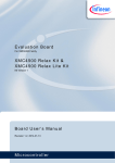
1
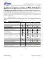
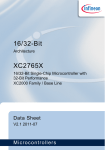
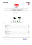
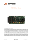
Evaluation Board
For XMC4000 Family
XMC4700
XMC4700
XMC4700
XMC4800
Relax
Relax
Relax
Relax
Lite Kit &
Kit for 5V Shields &
Kit &
EtherCAT Kit
Kit Version 1
Board User‘s Manual
Revision 1.0, 2015-11-20
Microcontroller
Edition 2015-11-20
Published by
Infineon Technologies AG
81726 Munich, Germany
© 2015 Infineon Technologies AG
All Rights Reserved.
Legal Disclaimer
The information given in this document shall in no event be regarded as a guarantee of conditions or
characteristics. With respect to any examples or hints given herein, any typical values stated herein and/or any
information regarding the application of the device, Infineon Technologies hereby disclaims any and all
warranties and liabilities of any kind, including without limitation, warranties of non-infringement of intellectual
property rights of any third party.
Information
For further information on technology, delivery terms and conditions and prices, please contact the nearest
Infineon Technologies Office (www.infineon.com).
Warnings
Due to technical requirements, components may contain dangerous substances. For information on the types in
question, please contact the nearest Infineon Technologies Office.
Infineon Technologies components may be used in life-support devices or systems only with the express written
approval of Infineon Technologies, if a failure of such components can reasonably be expected to cause the
failure of that life-support device or system or to affect the safety or effectiveness of that device or system. Life
support devices or systems are intended to be implanted in the human body or to support and/or maintain and
sustain and/or protect human life. If they fail, it is reasonable to assume that the health of the user or other
persons may be endangered.
XMC4700/XMC4800 Relax Kit Series-V1
Revision History
Page or Item
Subjects (major changes since previous revision)
Revision 1.0,
2015-11-20
Initial Version
Trademarks of Infineon Technologies AG
AURIX™, C166™, CanPAK™, CIPOS™, CIPURSE™, EconoPACK™, CoolMOS™, CoolSET™,
CORECONTROL™, CROSSAVE™, DAVE™, EasyPIM™, EconoBRIDGE™, EconoDUAL™, EconoPIM™,
EiceDRIVER™, eupec™, FCOS™, HITFET™, HybridPACK™, I²RF™, ISOFACE™, IsoPACK™, MIPAQ™,
ModSTACK™, my-d™, NovalithIC™, OptiMOS™, ORIGA™, PRIMARION™, PrimePACK™, PrimeSTACK™,
PRO-SIL™, PROFET™, RASIC™, ReverSave™, SatRIC™, SIEGET™, SINDRION™, SIPMOS™,
SmartLEWIS™, SOLID FLASH™, TEMPFET™, thinQ!™, TRENCHSTOP™, TriCore™.
Other Trademarks
Advance Design System™ (ADS) of Agilent Technologies, AMBA™, ARM™, MULTI-ICE™, KEIL™,
PRIMECELL™, REALVIEW™, THUMB™, µVision™ of ARM Limited, UK. AUTOSAR™ is licensed by
AUTOSAR development partnership. Bluetooth™ of Bluetooth SIG Inc. CAT-iq™ of DECT Forum.
COLOSSUS™, FirstGPS™ of Trimble Navigation Ltd. EMV™ of EMVCo, LLC (Visa Holdings Inc.). EPCOS™
of Epcos AG. FLEXGO™ of Microsoft Corporation. FlexRay™ is licensed by FlexRay Consortium.
HYPERTERMINAL™ of Hilgraeve Incorporated. IEC™ of Commission Electrotechnique Internationale. IrDA™
of Infrared Data Association Corporation. ISO™ of INTERNATIONAL ORGANIZATION FOR
STANDARDIZATION. MATLAB™ of MathWorks, Inc. MAXIM™ of Maxim Integrated Products, Inc.
MICROTEC™, NUCLEUS™ of Mentor Graphics Corporation. Mifare™ of NXP. MIPI™ of MIPI Alliance, Inc.
MIPS™ of MIPS Technologies, Inc., USA. muRata™ of MURATA MANUFACTURING CO., MICROWAVE
OFFICE™ (MWO) of Applied Wave Research Inc., OmniVision™ of OmniVision Technologies, Inc.
Openwave™ Openwave Systems Inc. RED HAT™ Red Hat, Inc. RFMD™ RF Micro Devices, Inc. SIRIUS™ of
Sirius Satellite Radio Inc. SOLARIS™ of Sun Microsystems, Inc. SPANSION™ of Spansion LLC Ltd.
Symbian™ of Symbian Software Limited. TAIYO YUDEN™ of Taiyo Yuden Co. TEAKLITE™ of CEVA, Inc.
TEKTRONIX™ of Tektronix Inc. TOKO™ of TOKO KABUSHIKI KAISHA TA. UNIX™ of X/Open Company
Limited. VERILOG™, PALLADIUM™ of Cadence Design Systems, Inc. VLYNQ™ of Texas Instruments
Incorporated. VXWORKS™, WIND RIVER™ of WIND RIVER SYSTEMS, INC. ZETEX™ of Diodes Zetex
Limited.
Last Trademarks Update 2011-02-24
Template: IFX_Template_2011-02-24.dot
XMC4700/XMC4800 Relax Kit Series-V1
Table of Contents
Table of Contents
Introduction ............................................................................................................................................................5
1.1
Key Features ........................................................................................................................................6
1.2
Block Diagram ......................................................................................................................................7
2
2.1
2.2
2.3
2.4
2.5
2.5.1
2.5.2
2.6
2.7
2.8
2.9
2.10
2.11
Hardware Description ........................................................................................................................7
Power Supply .....................................................................................................................................10
Pin Header X1 and X2 .......................................................................................................................11
Arduino™ Compatible Connector ......................................................................................................12
User Push Buttons and User LEDs....................................................................................................13
Debugging and UART-to-USB Communiction ...................................................................................13
On-board Debug Probe ......................................................................................................................13
Cortex™ Debug Connector (10-pin) ..................................................................................................13
Reset ..................................................................................................................................................14
CAN Transceiver ................................................................................................................................14
Serial Flash Memory ..........................................................................................................................14
microSD Card.....................................................................................................................................15
Ethernet..............................................................................................................................................15
Boot Option ........................................................................................................................................15
3
3.1
3.2
3.3
Production Data................................................................................................................................16
Schematics.........................................................................................................................................16
Components Placement and Geometry.............................................................................................22
List of Material ....................................................................................................................................23
List of Figures
Figure 1
Figure 2
Figure 3
Figure 4
Figure 5
Figure 6
Figure 7
Figure 8
Figure 9
Figure 10
Figure 11
Figure 12
Figure 13
Figure 14
Block Diagram of the XMC4700/XMC4800 Relax Kit Series-V1 .........................................................7
XMC4700 Relax Lite Kit .......................................................................................................................8
XMC4700 Relax Kit for 5V Shields ......................................................................................................8
XMC4700 Relax Kit ..............................................................................................................................9
The XMC4800 Relax EtherCAT Kit includes the XMC EtherCAT PHY Board ....................................9
Power Supply Concept.......................................................................................................................10
Signal mapping of the pin headers X1 and X2...................................................................................11
Mapping of Arduino™ Functions to XMC Pin Functions....................................................................12
Relax Kit Schematic: MCU, Push Buttons, LEDs, Reset Button, Crystals, USB ...............................17
Relax Kit Schematic: OBD Probe, Ethernet, Quad-SPI Memory, microSD Card Slot.......................18
Relax Kit Schematic: Pin Header, Voltage Level Shifter, Power Supply, CAN transceiver...............19
XMC EtherCAT Phy Board Schematic: Input and Output Phy ..........................................................20
XMC EtherCAT Phy Board Schematic: Power, Connectors, LEDs ...................................................21
Components Placement and Geometry.............................................................................................22
List of Tables
Table 1
Table 2
Table 3
Table 4
Table 5
Table 6
Table 7
Table 8
Table 9
Table 10
Table 11
Table 12
Kit Specification....................................................................................................................................5
Kit Features of Assembly Versions ......................................................................................................6
XMC4700/XMC4800 Pin Mapping for User LEDs .............................................................................13
XMC4700/XMC4800 Pin Mapping for User Push Buttons.................................................................13
XMC4700/XMC4800 Pins Mapping for Debugging and UART-Communication ...............................13
Pin Assignment of the Cortex™ Debug Connector (X102)................................................................13
CAN Signals and XMC4700/XMC4800 Pin Mapping.........................................................................14
XMC4700/XMC4800 Pins Mapping for Serial Flash Memory............................................................14
XMC4700/XMC4800 Pins Mapping for microSD Card ......................................................................15
XMC4700/XMC4800 Pins used for Ethernet .....................................................................................15
Boot Mode Selection with external Pull Resistors..............................................................................15
List of Material ....................................................................................................................................23
Board Users Manual
4
Revision 1.0, 2015-11-20
XMC4700/XMC4800 Relax Kit Series-V1
Introduction
1
Introduction
This document describes the features and hardware details of the XMC4700/XMC4800 Relax Kit Series-V1
®
®
equipped with an ARM Cortex -M4 based XMC™ Microcontroller from Infineon Technologies AG.
It can be used with a wide range of development tools including Infineon’s free of charge Eclipse based IDE
DAVE. The XMC4700/XMC4800 Relax Kit Series-V1 are designed to evaluate the capabilities of the
XMC4700 / XMC4800 Microcontroller. Table 1 shows its specification.
Table 1
Kit Specification
®
®
Processor
Infineon’s ARM Cortex -M4 XMC4700 or XMC4800 Microcontroller in LQFP144
package (order number XMC4700-F144K2048 or XMC4800-F144K2048)
Flash Memory
2048 kB
Data Memory
352 kB
Dimensions
66 x 99 mm (66 x 101 mm with connectors)
• 12 MHz and 32.768 kHz crystal for CPU
• 25 MHz crystal for Ethernet Phy
• 5V external powering
• Micro-AB USB Connector interface or
• On-Board Debugger USB interface
Clock Crystals
Power
Connectors
Debugger
Others
•
•
•
•
•
•
•
Arduino™ compatible connectors
All relevant XMC™ pins available on expansion pads (X1, X2)
All EtherCAT signals available on expansion pads (X1, X2)
Ethernet interface via RJ45 jack
microUSB
microSD-Card slot
Serial Wire Debug interface (2x5, 50 mil pitch) to XMC™
(on board debugger can be overridden by externally connected debugger)
On-Board J-Link Debug Probe via USB supporting
• Serial Wire Debug (SWD)
• UART-to-USB bridge (virtual COM)
• On-board debug probe, based on XMC4200 Microcontroller
• Ethernet Phy
• CAN transceiver
• 32 Mbit Quad-SPI Flash Memory
• 2 user push-buttons, 2 user LEDs
• Reset push-button
The XMC4700/XMC4800 Relax Kit Series-V1 are available in four different assembly versions differentiating in
features:
•
•
•
•
XMC4700 Relax Lite
XMC4700 Relax for 5V Shields
XMC4700 Relax
XMC4800 Relax EtherCAT
®
The XMC4700 Relax Kit and the XMC4800 Relax EtherCAT Kit feature with an Ethernet-enabled
communication option, e.g. to run an embedded web server. You can store your own HTML web pages on a
microSD Card or control the XMC4700 / XMC4800 via the web browser on your PC.
Additional voltage level shifters and Aruino connection header on theXMC4700 Relax Kit for 5V Shields allow
the usage of Arduino™ shields with 3.3V or 5V logic level.
Board Users Manual
5
Revision 1.0, 2015-11-20
XMC4700/XMC4800 Relax Kit Series-V1
Introduction
The embedded web server application is not supported by the KXMC4700 Relax Lite Kit and the
XMC4700 Relax Kit for 5V Shields, because some components e.g. for Ethernet and SD-Card are not
assembled.
®
The XMC4800 Relax EtherCAT Kit is assembled with a XMC4800 (pin compatible to XMC4700) and comes
®
together with a top-mounted XMC EtherCAT Phy Board. It’s a complete development kit for EtherCAT slave
devices and the XMC4800 is powerful and functional enough to make this board an ideal choice for the
®
development engineers of EtherCAT slaves such as servo drives and intelligent I/O devices.
All boards are marked with “XMC4700/XMC4800 Relax Kit Series-V1” and can be distinguished by the
assembled devices (see pictures in chapter 2). These boards are neither cost nor size optimized and do not
serve as a reference design.
1.1
Key Features
Table 2 summarizes the features of the different assembly versions of the XMC4700/XMC4800 Relax Kit
Series-V1.
Table 2
Kit Features of Assembly Versions
Feature
XMC4700
Relax Lite
Kit
XMC4700
Relax Kit for
5V Shields
XMC4700
Relax Kit
XMC4800
Relax
®
EtherCAT Kit
XMC4700 Microcontroller
XMC4800 Microcontroller
On-board Debug Probe with USB interface
supporting SWD + SWO
Virtual COM Port via Debug Probe
2 x User Push-Buttons and
2 x User LED and
1 x Reset Push-Button
Voltage Regulator 5 V -> 3.3 V
USB (Micro USB Plug)
12 MHz Crystal
32.768 kHz RTC Crystal
Arduino™ compatible connector and voltage level
shifter for 3.3 V / 5 V Arduino™ shields
0 Ohm Bridges for 3.3 V Arduino™ shields
Ethernet PHY and RJ45 Jack
32 Mbit Quad-SPI Flash Memory
microSD Card Slot
CAN Transceiver
Pin Header at X1 and X2 with mounted
XMC™ EtherCAT Phy Board
Note: Arduino is a trademark of Arduino Smart Projects S.r.l., Italy
Board Users Manual
6
Revision 1.0, 2015-11-20
XMC4700/XMC4800 Relax Kit Series-V1
Hardware Description
1.2
Block Diagram
The block diagram in Figure 1 shows the main components of the XMC4700/XMC4800 Relax Kit Series-V1 and
their interconnections. There are following main building blocks:
•
XMC4700 / XMC4800 Microcontroller in a LQFP144 package
•
On-board USB debug probe based on XMC4200 for SWD, SWV and Virtual COM Port support
•
Ethernet Phy with RJ45 Plug
•
Two 40-pin header X1 and X2
•
Connection Header for Arduino™
•
On-board power generation
•
2 User Push-Buttons, 2 User LEDs, Reset Push-Button
•
Micro-AB USB Plug
•
microSD Card Slot
•
CAN Transceiver
•
Quad SPI Flash
XMC4700 / XMC4800
Relax Kit Series-V1
25 MHz
Crystal
RJ45
ETH
PHY
micro
SD
SD/MMC
SDMMC
12 MHz
Crystal
OCS
Debug*
(10pin)
Micro
USB
SWD
SWV
5V
SWD
SWV
UART
XMC4200
Debug IC
Debug
LED
COM
LED
Debug,
U0C0
EVR
3.3V
GPIO
P15.13
BUTTON1
P5.9
LED1
BUTTON2
P15.12
LED1
P5.8
Pin Header Arduino™ (DIGITAL)
RMII
Power
LED
Voltage
Regulator
Not assembled in
Lite and ARDUINO
version
Pin Header X1
2x20, 0.1"
Assembled in
ARDUINO version
only
ETH
BSL
PORST
#
EtherCAT, U1C0, CCU80, ADC,
DAC, CAN, ERU0
RX/TX, SPI,
PWM, INT, IO
Level
Shifter
U2C1
qSPI
Flash
RTC
32.768
kHz
USB
USB
XMC4700 / XMC4800
Microcontroller
EtherCAT, U0C1, U2C0, ERU1,
CCU4, CCU8
CAN
CAN
Trans.
2x3
pin
Micro
USB
ADC
Pin Header Arduino™ (ANALOG IN)
RESET
Pin Header X2
2x20, 0.1"
Assembeld in
EtherCAT version
only
Not assembled in
any versions
Figure 1
Block Diagram of the XMC4700/XMC4800 Relax Kit Series-V1
2
Hardware Description
BlockDiag.emf
The following chapters give a detailed description of the board hardware and how it can be used. The different
assembly versions of the kits series are shown in Figure 2, Figure 3, Figure 4 and Figure 5.
Board Users Manual
7
Revision 1.0, 2015-11-20
XMC4700/XMC4800 Relax Kit Series-V1
Hardware Description
Figure 2
Figure 3
XMC4700 Relax Lite Kit
XMC4700 Relax Kit for 5V Shields
Board Users Manual
8
Revision 1.0, 2015-11-20
XMC4700/XMC4800 Relax Kit Series-V1
Hardware Description
Figure 4
XMC4700 Relax Kit
Figure 5
The XMC4800 Relax EtherCAT Kit includes the XMC EtherCAT PHY Board
Board Users Manual
9
Revision 1.0, 2015-11-20
XMC4700/XMC4800 Relax Kit Series-V1
Hardware Description
2.1
Power Supply
The XMC4700/XMC4800 Relax Kit Series-V1 must be supplied by an external 5 Volt DC power supply
connected to any of the micro USB plugs (X100, X101). Out of the box with the pre-programmed web server
application and the on-board debug probe in operation theXMC4700 Relax Kit typically draws about 250 mA,
the XMC4700 Relax Lite Kit and the XMC4700 Relax Kit for 5V Shields without the web server capabilities
draws about 200 mA and the XMC4800 Relax EtherCAT Kit together with the XMC EtherCAT Phy Board in
an EtherCAT network draws about 500 mA. This current can be delivered via the USB plug of a PC, which is
specified to deliver up to 500 mA. The green Power LED (VDD3.3) indicates the presence of the generated
3.3 V supply voltage.
On-board reverse current protection diodes will ensure safe operation in case power is provided through both
USB plugs at the same time. These protection diodes allows to use the on-board debug probe connected with a
PC/Notebook via X101 and a second host PC/Laptop connected with the XMC4700 / XMC4800 Relax Kit via
X100.
If the board is powered via a USB plug, it’s not recommended to apply an additional 5 Volt power supply to one
of the 5 Volt power pins (VDD5, 5 V) on the pin headers X1 or X2 or the Arduino™ Power header, because
there is no protection against reverse current into the external power supply. These power pins can be used to
power an external circuit. But care must be taken not to draw more current than USB can deliver. A PC as USB
host typically can deliver up to 500 mA current. If higher currents are required and in order to avoid damages on
the USB host the use of an external USB power supply unit which is able to deliver higher currents than 500 mA
is strongly recommended.
After power-up the green DEBUG LED starts blinking. In case there is a connection to a PC via the Debug USB
plug X101 and the USB Debug Device drivers are installed on this PC, the DEBUG LED will turn from blinking to
constant illumination.
ARDUINO POWER Pin Header
XMC4700 / XMC4800
Relax Kit Series-V1
IC402
+5V
IC400, IC401
IFX1051LE
CAN
Transceiver
Ethernet
Phy, QSPI
Flash
IC100
Infineon
JP300, IOREF
3.3V
IC300, IC301
X100
Micro
USB
Power
LED
Voltage Level
Shifter for
ARDUINO
+5V
Infineon
3.3V
X101
+5V
+5V
Infineon
Infineon
IC101
IC102
Micro
USB
XMC4700 /
XMC4800
Microcontroller
IFX1117
Lin. Voltage
Regulator
3.3V
Infineon
XMC4200
Debug IC
Infineon
Pin Header X1 and X2
2x20, 0.1"
Power_BlockDiag.emf
Figure 6
Power Supply Concept
Board Users Manual
10
Revision 1.0, 2015-11-20
XMC4700/XMC4800 Relax Kit Series-V1
Hardware Description
2.2
Pin Header X1 and X2
The pin headers X1 and X2 can be used to extend the evaluation board or to perform measurements on the
XMC4700 / XMC4800. Figure 7 shows the available GPIOs / signals at these pin headers. The pin table is also
printed onto the bottom side of the PCB.
Pin Header X2
GND
40 39 GND
GND
38 37 GND
Pin Header X1
GND
VDD3.3 36 35 CANL
40 39
GND
VDD3.3 38 37
GND
VDD3.3 36 35 VDD5
VDD3.3 34 33 CANH
P5.11
34 33 P5.10
RST#
32 31 VDD5
P1.14
32 31 P2.13
HIB_1
30 29 HIB_0
P14.8
30 29 P14.9
P2.6
28 27 P5.7
P15.14 28 27 P15.15
P5.6
26 25 P5.5
P14.6
P5.4
24 23 P5.3
P14.12 24 23 P14.13
P5.2
22 21 P5.1
P14.14 22 21 P14.15
P5.0
20 19 P1.15
P15.2
20 19 P15.3
P6.6
18 17 P6.5
P15.4
18 17 P15.5
P6.1
16 15 P5.3
P15.7
16 15 P15.6
P6.2
14 13 P6.1
P3.9
14 13
P3.1
P6.0
12 11 P1.2
P0.9
12 11
P3.2
P0.8
10 9
P0.0
10 9
P0.10
P3.3
8
7 P3.14
P0.2
8
7
P0.1
P0.15
6
5 P0.14
P0.4
6
5
P0.3
P0.12
4
3 P3.11
P0.6
4
3
P0.5
P3.12
2
1 P3.13
P0.11
2
1
P3.4
P0.7
26 25 P14.7
(Top
View)
Figure 7
Signal mapping of the pin headers X1 and X2
Board Users Manual
11
Revision 1.0, 2015-11-20
XMC4700/XMC4800 Relax Kit Series-V1
Hardware Description
2.3
Arduino™ Compatible Connector
The mapping of GPIOs and XMC pin functions to Arduino™ compatible functions can be found in Figure 8. The
Arduino™ compatible connector supports
•
•
•
•
•
•
SPI interface (SPI_xxx)
I2C interface (I2C_xxx)
UART interface (UART_xxx)
PWM signal outputs (PWM0-5)
ADC input (ADC0-5)
Interrupt input (INT0-1)
(Top View)
N.C.
1
IOREF
2
RESET#
3V3
3
4
5
6
GND
7
N.C.
8
P0.13 /
P14.5
I2C_SCL / U1C1.SCLKOUT
ADC5 / VADC.G0CH0
9
P3.15 /
P14.4
I2C_SDA: U1C1.DOUT0
ADC4: VADC.G0CH1
8
VAREF
7
GND
6
P3.9
5
P3.7
SPI_MISO: U2C0.DX0C
4
P3.8
SPI_MOSI: U2C0.DOUT0
3
P3.10
SPI_CS: U2C0.SELO0
2
P1.11
1
P1.10
IO2: P1.10
8
P1.9
IO1: P1.9
7
P2.11
AREF: VAREF
SPI_CLK: U2C0.SCLKOUT
1
6
P2.12
P14.1
2
5
P1.8
IO0: P1.8
4
P1.1
INT1: ERU0.3A0
3
P1.0
INT0: ERU0.3B0
2
P2.14
UART_TXD: U1C0.DOUT0
1
P2.15
UART_RXD: U1C0.DX0C
4
I2C_SCL / U1C1.DOUT0
ADC4: VADC.G2CH0
P14.4 /
P3.15
5
I2C_SCL / U1C1.SCLKOUT
ADC5 / VADC.G2CH1
P14.5 /
P0.13
6
PWM5: CCU41.OUT2
SPI_MOSI: U2C0.DOUT0
ANALOG IN
3
P14.3
DIGITAL
P14.0
P14.2
5
3
1
6
4
2
RESET#
P3.7
GND
5V
P3.8
P3.9
PWM4: CCU41.OUT0
PWM2: CCU80.OUT22
ADC1: VADC.G1CH1
ADC2: VADC.G1CH2
PWM5: CCU41.OUT2
PWM3: CCU81.OUT11
ADC0: VADC.G0CH0
ADC3 / VADC.G1CH3
Figure 8
POWER
5V
GND
10
PWM1: CCU81.OUT33
PWM0: CCU40.OUT2
SPI_MISO: U2C0.DX0C
SPI_CLK: U2C0.SCLKOUT
Ard uino_Pin_Mappin g.emf
Mapping of Arduino™ Functions to XMC Pin Functions
The XMC4700 Relax Kit for 5V Shields features bi-directional voltage level shifter and therefor supports 5 V
Arduino™ shields. Jumper JP300 (IOREF) determines whether the Arduino™ shield is driven with 5 V or 3.3 V.
Analog input signals ADC0-5 are limited to 3.3 V input voltage. Primarily ADC0 to ADC3 should be used as
analog input, because there is no additional circuit connected to these pins, whereas ADC4 and ADC5 have
additional circuitry and require an input signal with lower input impedance.
Note: Parallel operation of I2C and ADC4 / ADC5 is not possible, because they share the same Arduino pins.
Board Users Manual
12
Revision 1.0, 2015-11-20
XMC4700/XMC4800 Relax Kit Series-V1
Hardware Description
2.4
User Push Buttons and User LEDs
The XMC4700/XMC4800 Relax Kit Series-V1 provides two push buttons and two LEDs. The port pins used can
be found in Table 3 and Table 4. These pins are used exclusively for this function and they are not mapped to
other devices or connectors.
Table 3
XMC4700/XMC4800 Pin Mapping for User LEDs
LED
XMC Pin
LED1
P5.9
LED2
P5.8
Table 4
XMC4700/XMC4800 Pin Mapping for User Push Buttons
Button
XMC Pin
BUTTON1
P15.13
BUTTON2
P15.12
2.5
Debugging and UART-to-USB Communiction
The XMC4700/XMC4800 Relax Kit Series-V1 supports debugging via 2 different channels:
•
•
On-board debug probe
10-pin Cortex™ Debug Connector (not assembled)
2.5.1
On-board Debug Probe
The on-board debug probe supports Serial Wire Debug (SWD) and UART communication. Both require the
installation of Segger’s J-Link Driver which is part of the DAVE™ installation. DAVE™ is a highly efficient
development platform for the XMC microcontroller families to simplify and shorten SW development. It can be
downloaded at www.infineon.com/dave. The latest Segger J-Link Driver can be downloaded at
http://www.segger.com/jlink-software.html. Table 5 shows the pin assignment of the XMC4700/XMC4800 used
for debugging and UART communication.
Table 5
XMC4700/XMC4800 Pins Mapping for Debugging and UART-Communication
Pin Funtion
Input/Output
XMC Pin
Data pin for Debugging via SWD
I/O
TMS
Clock pin for Debugging ia SWD
O
TCK
Transmit pin for UART communication (PC_RX)
O
P1.5 (U0C0.DOUT)
Receive pin for UART communication (PC_TX)
I
P1.4 (U0C0.DX0B)
2.5.2
Cortex™ Debug Connector (10-pin)
The 10-pin Cortex™ Debug Connector supports Serial Wire Debug (SWD) and Serial Wire Viewer (SWV). The
pin assignment of the Cortex™ Debug Connector is shown in Table 6.
Table 6
Pin Assignment of the Cortex™ Debug Connector (X102)
Pin No.
Signal Name
Description
1
VCC
+3.3 V
2
TMS
Serial Wire Data I/O
3
GND
Ground
4
TCK
Serial Wire Clock
5
GND
Ground
6
SWV
Serial Wire Viewer (Trace Data Out)
Board Users Manual
13
Revision 1.0, 2015-11-20
XMC4700/XMC4800 Relax Kit Series-V1
Hardware Description
Pin No.
Signal Name
Description
7
Key
Key
8
NC
Not connected
9
GND_Detect
Ground detect
10
RESET
Rest (active low)
2.6
Reset
The reset pin (PORST#) of the XMC4700/XMC4800 is a bi-directional pin in open drain mode. An internal pullup resistor keeps the PORST# pin high during normal operation. A low level at this pin will force a hardware
reset. In case of a MCU internal reset the PORST# pin will drive a low signal.
A reset signal can be issued by
• the on-board Reset Button (SW102, “RESET”)
• the on-board debug probe (IC101.46)
• the external debugger connected to the 10-pin Cortex™ Debug probe connector (X102)
• the Arduino Power Header (X302.3, “RESET”)
• the pin header X2 (X2.32, “RST#”)
An XMC™ internal circuit always ensures a save Power-on-Reset. XMC™ does not require any additional
external components to generate a reset signal during power-up.
2.7
CAN Transceiver
The XMC4700 Relax Kit and the XMC4800 Relax EtherCAT Kit provide a CAN interface via the X2 connector.
Infineon’s high speed CAN transceiver IFX1051LE for industrial application supports 3.3V I/O logic and is
suitable for 12V and 24V bus systems with an excellent EMC performance. The CAN bus (signals CANH,
CANL) is not terminated by a 120 Ohm and needs to be terminated externally.
Table 7
Signal
Name
CAN Signals and XMC4700/XMC4800 Pin Mapping
Pin No. at Pin Header X2
XMC Pin, XMC Function
CANH
X2.33
-
CANL
X2.35
-
CAN_TX
-
P1.12, CAN.N1_TXD
CAN_RX
-
P1.13, CAN.N1_RXDC
2.8
Serial Flash Memory
The XMC4700 Relax Kit and the XMC4800 Relax EtherCAT Kit provide a 32 Mbit serial flash memory from
Micron (type: N25Q032A) interfaced to XMC4700/XMC4800 through a SPI interface. The SPI interface can be
configured as single, dual or quad SPI.
Table 8
XMC4700/XMC4800 Pins Mapping for Serial Flash Memory
XMC Pin
Function in qSPI Mode, XMC Function
Function in SPI Mode, XMC Function
P4.2
Clock, U2C1.SCLKOUT
Clock, U2C1.SCLKOUT
P4.3
Chip Select, U2C1.SELO2
Chip Select, U2C1.SELO2
P4.7
Data Line 0 I/O, U2C1.DOUT0
Master Out Slave In (MOSI, MTSR), U2C1.DOUT0
P4.6
Data Line 1, U2C1.DOUT1
Master In Slave Out (MISO, MRST), U2C1.DX0E
P4.4
Data Line 3, U2C1.DOUT3
HOLD (low active)
P4.5
Data Line 2, U2C1.DOUT2
Write Protection (low active)
Board Users Manual
14
Revision 1.0, 2015-11-20
XMC4700/XMC4800 Relax Kit Series-V1
Hardware Description
2.9
microSD Card
The XMC4700 Relax Kit and the XMC4800 Relax EtherCAT Kit provide a microSD card slot (X401). The
microSD card can be operated in SD mode via the SDMMC peripheral or in SPI mode via the USIC0 Channel1
(U0C1) of the XMC4700/XMC4800.
Table 9
XMC4700/XMC4800 Pins Mapping for microSD Card
XMC Pin
Function in SD Mode, XMC Function
Function in SPI Mode, XMC Function
P3.6
Clock, SDMMC.CLK_OUT (IN)
Clock, U0C1.SCLKOUT
P3.5
Command Line, SDMMC.CMD_OUT (IN)
Master Out Slave In (MOSI, MTSR), U0C1.DOUT0
P4.0
Data Line 0, SDMMC.DATA0_OUT (IN)
Master In Slave Out (MISO, MRST), U0C1.DX0E
P1.6
Data Line 1, SDMMC.DATA1_OUT (IN)
Unused
P1.7
Data Line 2, SDMMC.DATA2_OUT (IN)
Unused
P4.1
Data Line 3, SDMMC.DATA3_OUT (IN)
Chip Select (CS) / Slave Select (SS), U0C1.SELO0
2.10
Ethernet
The XMC4700 Relax Kit and the XMC4800 Relax EtherCAT Kit provide an Ethernet Phy and RJ45 plug.
Table 10
XMC4700/XMC4800 Pins used for Ethernet
XMC Pin
Ethernet Function
XMC Function
P15.9
Carrier Sense / Receive Data Valid
ETH0.CRS_DVC
P15.8
Clock Input
ETH0.CLK_RMIIC
P2.10
LED
GPIO P2.10
P2.9
Transmit Data Line 1
ETH0.TXD1
P2.8
Transmit Data Line 0
ETH0.TXD0
P2.5
Transmit Enable
ETH0.TX_EN
P2.4
Receive Error
ETH0.RXERA
P2.3
Receive Data Line 1
ETH0.RXD1A
P2.2
Receive Data Line 0
ETH0.RXD0A
P2.0
Management Data In/Out
ETH0.MDIB / ETH0.MDO
P2.7
Management Data Clock
ETH0.MDC
P1.3
Interrupt (disabled via solder jumper R401) GPIO P1.3
2.11
Boot Option
During power-on-reset the XMC4700/XMC4800 latches the signal level at the pins TMS and TCK. Based on the
logic levels latched at these pins after reset the XMC4700/XMC4800 starts booting in different modes. TMS and
TCK pins are used for debugging and by default program execution is always starting from on-chip flash (normal
mode).
The XMC4700/XMC4800 Relax Kit Series-V1 does not support the selection of the boot options by switches
directly. In case of no external debug probe is used the boot mode can be influenced by applying 1 kOhm pullup- or pull-down resistors to TMS and TCK pins. These pins are available at the 10-pin debug connector X102.
Table 11
Boot Mode Selection with external Pull Resistors
Logic Level at TMS
during Reset
Logic Level at TCK
during Reset
Boot Mode
High
Low
Normal Mode (boot from on-chip flash) (DEFAULT)
Board Users Manual
15
Revision 1.0, 2015-11-20
XMC4700/XMC4800 Relax Kit Series-V1
Production Data
Logic Level at TMS
during Reset
Logic Level at TCK
during Reset
Boot Mode
Low
Low
ASC BSL Mode (boot from UART)
High
High
BMI Customized Boot Mode
Low
High
CAN BSL Mode (boot from CAN)
3
Production Data
This chapter covers schematics, board dimensions, component placement and the list of material.
3.1
Schematics
In the following figures shows the schematics of the XMC4700/XMC4800 Relax Kit Series-V1 and the XMC
EtherCAT Phy Board-V1:
•
•
•
•
•
Figure 9: Relax Kit Schematic: MCU, Push Buttons, LEDs, Reset Button, Crystals, USB
Figure 10: Relax Kit Schematic: OBD Probe, Ethernet, Quad-SPI Memory, microSD Card Slot
Figure 11: Relax Kit Schematic: Pin Header, Voltage Level Shifter, Power Supply, CAN transceiver
Figure 12: XMC EtherCAT Phy Board Schematic: Input and Output Phy
Figure 13: XMC EtherCAT Phy Board Schematic: Power, Connectors, LEDs
Board Users Manual
16
Revision 1.0, 2015-11-20
E
1
2
3
4
5
3 D1
D100 1
1
GND GND GND GND
R107 22R
R108 22R
2
A
C
GND
VDD3.3
D101
BAS3010A-03W
C103 10uF/10V
L100 BLM18PG600
C104 10uF/10V
X100
C105 100nF
ADC_3
ADC_2
ADC_1
ADC_0
SDA, ADC_4
SCL, ADC_5
ECAT0.P0_TXD3
ECAT0.P0_TXD2
ECAT0.P0_TXD1
ECAT0.P0_LINK_ACT
ECAT0.P0_TXD0
ECAT0.P0_TX_ENA
ECAT0.PHY_CLK
C106 100nF
USB Connector
1M
P0.15
P0.14
P0.13
P0.12
P0.11
P0.10
P0.9
P0.8
P0.7
P0.6
P0.5
P0.4
P0.3
P0.2
P0.1
P0.0
135
136
137
138
139
3
4
127
128
140
141
142
143
144
1
2
3
31
32
33
34
51
52
35
36
37
38
39
40
41
42
95
96
97
98
99
100
101
125
90
61
VDDC 19
126
86
62
18
15
16
17
24
HIB_IO_1 20
HIB_IO_0 21
USB_DM
USB_DP
VDD3.3
P14.15
P14.14
P14.13
P14.12
P14.9
P14.8
P14.7
P14.6
P14.5
P14.4
P14.3
P14.2
P14.1
P14.0
P6.6
P6.5
P6.4
P6.3
P6.2
P6.1
P6.0
QSPI_IO0
QSPI_IO1
QSPI_IO2
QSPI_IO3
QSPI_CS
QSPI_CLK
MMC_DAT3
MMC_DAT0
C107 100nF
D
C100 100nF
117
118
119
120
121
122
123
124
VDD5
C
ZX62-AB-5PA
R106
2
D2
94
102
103
104
105
106
113
114
115
116
107
108
109
110
111
112
C108 100nF
B
ESD8V0L2B-03L
ECAT0.P0_LINKB P1.15
ECAT_LED_3 P1.14
CAN_RX
CAN_TX
PWM_3 P1.11
IO_2 P1.10
IO_1 P1.9
IO_0 P1.8
MMC_DAT2
MMC_DAT1
P1.5
P1.4
ETH_Interrupt P1.3
ECAT_LED_4 P1.2
INT_1, PWM_0 P1.1
INT_0 P1.0
C109 100nF
A
C101 10uF/10V
ECAT_LED_8
ECAT_LED_7
SCL, ADC_5
ECAT0.MDO
ECAT0.P1_RXD0A
ECAT0.P1_TX_CLKA
ECAT0.P1_RX_DVA
ECAT0_LED_RUN
ECAT0_LED_ERR
ECAT0.P1_RXD1A
ECAT0.P1_RXD2A
ECAT0.P1_RXD3A
ECAT0.P1_TXD3
ECAT0.P1_TXD2
ECAT0.P1_RX_CLKA
ECAT0.PHY_RST
C110 100nF
Target Device
C111 100nF
XMC4700 / XMC4800 Relax Kit Series-V1
C112 100nF
GND
VDDC3
VDDC2
VDDC1
VDDC
VDDP3
VDDP2
VDDP1
VDDP
Analog
Digital
IC100
VSSO
VSS
EPAD
PORST#
TCK
TMS
XTAL1
XTAL2
RTC_XTAL_1
RTC_XTAL_2
VAREF
VAGND
VDDA
VSSA
P15.15
P15.14
P15.13
P15.12
P15.9
P15.8
P15.7
P15.6
P15.5
P15.4
P15.3
P15.2
P5.11
P5.10
P5.9
P5.8
P5.7
P5.6
P5.5
P5.4
P5.3
P5.2
P5.1
P5.0
P2.15
P2.14
P2.13
P2.12
P2.11
P2.10
P2.9
P2.8
P2.7
P2.6
P2.5
P2.4
P2.3
P2.2
P2.1
P2.0
P3.15
P3.14
P3.13
P3.12
P3.11
P3.10
P3.9
P3.8
P3.7
P3.6
P3.5
P3.4
P3.3
P3.2
P3.1
P3.0
4
XMC4700/XMC4800_LQFP144
Supply
Hibernate/RTC
USB_DUSB
USB_D+
VBUS
HIB_IO_1
HIB_IO_0
VBAT
P14.15
P14.14
P14.13
P14.12
P14.9
P14.8
P14.7
P14.6
P14.5
P14.4
P14.3
P14.2
P14.1
P14.0
P6.6
P6.5
P6.4
P6.3
P6.2
P6.1
P6.0
P4.7
P4.6
P4.5
P4.4
P4.3
P4.2
P4.1
P4.0
P1.15
P1.14
P1.13
P1.12
P1.11
P1.10
P1.9
P1.8
P1.7
P1.6
P1.5
P1.4
P1.3
P1.2
P1.1
P1.0
P0.15
P0.14
P0.13
P0.12
P0.11
P0.10
P0.9
P0.8
P0.7
P0.6
P0.5
P0.4
P0.3
P0.2
P0.1
P0.0
4
89
85
EXP
91
93
92
87
88
22
23
46
45
7
GND
100nF
RTC_XTAL_2
GND
GND
Q400
32.768KHZ
GND
S
S1
P
C119 P1
SW102
TMPS2-SMD
RTC_XTAL_1
GND
C120
10nF
P
P1
BUTTON2
GND
GND
V1 / 01.09.2015
S
S1
BUTTON 2
SW101
TMPS2-SMD
S
S1
BUTTON 1
SW100
TMPS2-SMD
5
6
Sheet: 1/3
8
14.09.2015 14:34:39
XMC4700_Relax-V1
GND
GND
GND
100nF
C118 P1
P
ADJ_3
The information given in this document shall in no event be regarded as a guarantee of conditions or
characteristics. With respect to any examples or hints given herein, any typical values stated herein and/or any
information regarding the application of the device, Infineon Technologies hereby disclaims any and all warranties
and liabilities of any kind, including without limitation, warranties of non-infringement of intellectual property rights
of any third party.
GND
RTC Crystal
GND
BUTTON1
ADJ_2
8
XMC4700 Relax Kit Series
GND
100nF
LED2
RESET#
Reset
LED1
Buttons & LEDs
ADJ_1
7
LED100
LED-RT/D/0603
Legal Disclaimer
GND
RESET#
TCK
TMS
510R/0402 Q100
12MHZ/S/3.2X2.5
GND
C115
100nF
ECAT0.P1_RX_ERRB
6
C114
ECAT0.P0_RXD3B
ECAT0.P0_RX_DVB
ECAT0.P0_TX_CLKB
ECAT0.P0_RX_CLKB
ECAT_LED_2
ECAT0.P0_RXD2
ECAT0.P0_RXD1
ECAT0.P0_RXD0
ECAT0.P0_RX_ERRB
PWM_2
PWM_1
UART_RX
UART_TX
ECAT0.P1_LINKA
ECAT0.MCLK
ECAT0.P1_TXD1
ECAT0.P1_TXD0
ECAT0.P1_TX_ENA
SDA, ADC_4
ECAT_LED_6
ECAT_LED_1
ECAT0.P1_LINK_ACT
ECAT_LED_5
SPI_CS, PWM_4
SPI_CLK
SPI_MOSI, PWM_5
SPI_MISO
R111
RTC_XTAL_1
RTC_XTAL_2
P15.15
P15.14
BUTTON1
BUTTON2
ETH_CRS
ETH_CLK
P15.7
P15.6
P15.5
P15.4
P15.3
P15.2
43
44
49
50
53
54
25
26
27
28
29
30
48
47
P5.11
P5.10
LED1
LED2
P5.7
P5.6
P5.5
P5.4
P5.3
P5.2
P5.1
P5.0
P2.15
P2.14
P2.13
P2.12
P2.11
P2.10
ETH_TXD1
ETH_TXD0
ETH_MDC
P2.6
ETH_TXEN
ETH_RXER
ETH_RXD1
ETH_RXD0
SWV
ETH_MDIO
P3.15
P3.14
P3.13
P3.12
P3.11
P3.10
P3.9
P3.8
P3.7
MMC_CLK
MMC_CMD
P3.4
P3.3
P3.2
P3.1
P3.0
55
56
57
58
77
78
79
80
81
82
83
84
59
60
63
64
65
66
67
68
75
76
69
70
71
72
73
74
133
134
8
9
10
11
12
13
14
129
130
131
132
5
6
7
5
BLM18PG600
3
C113 10uF/10V
R109
VAREF
no ass./0R
R110
0R L101
BLM18PG600
VDD3.3
L102
C116 15pF
LED1
LED2
2mA LED
2mA LED
R112
R113
VDD3.3
2
C117 15pF
17
R116
VDD3.3
R114
VDD3.3
R115
680R
680R
LED101
LED-RT/D/0603
10K/0402
10k
10k
Board Users Manual
C400 15pF
Figure 9
C401 15pF
1
E
D
C
B
A
XMC4700/XMC4800 Relax Kit Series-V1
Production Data
Relax Kit Schematic: MCU, Push Buttons, LEDs, Reset Button, Crystals, USB
Revision 1.0, 2015-11-20
C102 10uF/10V
/ / m
uc s dn3 1 . e u. i nf i ne on. c om
/ Ro e m
m
e l m
/ M
y
E
doc um
D
C
15pF
C121
e n t s / Bo o t l o a d e r _ Re m
a ppi ng/ qr c ode . bm
p
GND
1
U1C0
DX0A-P0.4
DOUT0-P0.5
GPIO-P0.6
RESET#
GPIO-P0.3
DEBUG_LED# GPIO-P0.2
AUX_LED#
GPIO-P0.1
RXD
TXD
RESET#
DEBUG_LED#
COM_LED#
2
U1C1
DX0D-P0.0
U0C1
DX2A-P2.3
DX1A-P2.4
DOUT0-P2.5
DX0A-P2.2
SPI Slave
CS_IN
CLK_IN
MISO
MOSI
UART2 (DM2)
RXD
TXD
TXACTIVE#
SWV
U0C0
DX0B-P1.4
DOUT0-P1.5
SCLKOUT-P1.1
SELO0-P1.0
SPI Master
MISO
MOSI
CLK_OUT
CS_OUT
Supply
31
6
41
28
5
3
4
7
10
19
20
11
12
13
14
15
16
R120
R121
3
22R/0402
22R/0402
2
4
6
8
10
C
TMS
TCK
SWV
GND
4
FTSH-105-01-F-D-K
no ass.
1
3
5
7
9
X102
GND
GND
DBGPRES#
GND
TCK
TCK
CS
GND
TMS
SWV
PC_TXD
PC_RXD
TMS
COM_LED
SWV
DEBUG_LED
P1.4
P1.5
RESET#
Level Shifter
No RESET Pin
UART
SPD
SWV
JTAG
Cortex Debug
VDDC1
VDDC
VDDP2
VDDP1
VDDP
USB_D+
HIB_IO_0
VBAT
P14.9
P14.8
P14.7
P14.6
P14.5
P14.4
P14.3
P14.0
USB USB_D-
Hibernate/RTC
XMC4200_QFN48
VSS
EPAD
PORST#
TCK
TMS
XTAL1
XTAL2
RTC_XTAL_1
RTC_XTAL_2
VAREF
VAGND
Analog
UART
RXD
TDI
TDO
TMS
TCK
32
34
33
29
30
8
9
18
17
27
EPAD
GND
DBGPRES#
WTCK
WTMS
510R/0402
On-board Debugger Concept
no ass.
1
2
3
4
5
X103
GND
15pF
GND
VDD3.3
Q101
R118
12MHZ/S/3.2X2.5
R119
B
VDD3.3
10k
P1.5
P1.4
P1.3
P1.2
P1.1
P1.0
100nF
C123
35
36
37
38
39
40
100nF
C124
Digital
4.7uF/10V
C125
VDD3.3
R122
510R/0402
VDD3.3
42
43
44
45
46
47
48
1
2
10uF/10V
C126
VDD3.3
VDD5
P0.8
P0.7
P0.6
P0.5
P0.4
P0.3
P0.2
P0.1
P0.0
10uF/10V
C127
BAS3010A-03W
R126
R127
D103
R124
L103
BLM18PG600
R123
RESET#
GND GND
1
P2.5
P2.4
P2.3
P2.2
P2.1
P2.0
D2
A
4k7/0402
10k/0402
LED102 680R VDD3.3
LED-GN/D/0603
2D102
3 D1
SWV
ESD8V0L2B-03L
A
100nF
C128
1
2
3
4
5
X101
GND GND
ETH_MDC
ETH_MDIO
ETH_CLK
ETH_TXEN
ETH_TXD0
ETH_TXD1
ETH_CRS
ETH_RXD0
ETH_RXD1
ETH_RXER
VDD3.3
8
7
11
10
16
19
20
21
15
13
12
17
14
1
2
GND
KSZ8081RNA
XI
XO
MDC
MDIO
REF_CLK
TXEN
TXD0
TXD1
CRS_DV
RXD0
RXD1
RXER
VDDIO
VDD_1.2
VDDA_3.3
IC400
GND
100nF
C413
R401
1
6
5
2
7
8
(IO0)
(IO1)
WP#
(IO2)
GND
22
EXP
9
18
23
3
4
5
6
24
VDD3.3
GND
GND
S1
S2
S3
S4
S5
7
RJ45
S1
S2
RA
RC
LA
LC
S1
S2
12
11
9
10
V1 / 01.09.2015
P2.10
Würth 7499010211A
NC
CG
RD-
CTR
RD+
TD-
CTT
TD+
X400
RESET#
8
5
6
Sheet: 2/3
8
13.11.2015 18:36:31
XMC4700_Relax-V1
G1
G2
G3
G4
G5
7
8
6
5
3
2
4
1
2
D401
1
BAT64-02V
L401
BLM18PG600
GND
QSPI_IO2
MOLEX-0475710001
DAT2
DAT3/CS_N
CMD/MOSI
VDD
CLK/SCK
GND
DAT0/MISO
DAT1
X401
R402
The information given in this document shall in no event be regarded as a guarantee of conditions or
characteristics. With respect to any examples or hints given herein, any typical values stated herein and/or any
information regarding the application of the device, Infineon Technologies hereby disclaims any and all warranties
and liabilities of any kind, including without limitation, warranties of non-infringement of intellectual property rights
of any third party.
P1
P2
P3
P4
P5
P6
P7
P8
3
4
1k
XMC4700 Relax Kit Series
GND
N25Q032A
CS#
CLK
DI
DO
HOLD#
(IO3)
VCC
IC401
GND
P_GND
REXT
INTRP
LED0
RXM
RXP
TXM
TXP
RST#
no ass./0R
P1.3
7
R406
Legal Disclaimer
MMC_DAT0
MMC_DAT1
MMC_CLK
MMC_DAT2
MMC_DAT3
MMC_CMD
QSPI_CS
QSPI_CLK
QSPI_IO0
QSPI_IO1
QSPI_IO3
GNDGND GNDGND GND
Micro SD-Card
qSPI Flash
C403
100nF
GND GND
6
2
1
5
Ethernet
2.2uF/10V
C405
R403
10uF/10V
IC101
R125
LED103 680R VDD3.3
LED-GN/D/0603
1M
22uF/10V
C402
C406 100nF
22uF/10V
C407
21
22
23
24
25
26
100nF
C129
C122
5 TH-Pads
2.54mm pitch
C131 100nF
L400
100nF
C408
R407
TCK
CS
SWV
100nF
C130
BLM18PG600
22pF
C409
1k R400
22pF
25MHz/50ppm
Q401
C410
10k
R408
R410 10k
4
10k
R411 10k
3
R412 10k
VDD3.3
R413 10k
2
R414 10k
BAT64-02V
6K49/0603
R409
D400 VDD3.3
100nF
C411
VDD3.3
10k
C404
1
VDD3.3
18
10k
Board Users Manual
100nF
120R
R404
VDD3.3
120R
R405
Figure 10
C412
On-board Debugger
E
D
C
B
A
XMC4700/XMC4800 Relax Kit Series-V1
Production Data
Relax Kit Schematic: OBD Probe, Ethernet, Quad-SPI Memory, microSD Card Slot
Revision 1.0, 2015-11-20
ZX62-AB-5PA
E
D
C
B
1
VDD3.3
IOREF
IO_1
PWM_2
PWM_1
IO_0
INT_1, PWM_0
INT_0
UART_TX
UART_RX
VDD3.3
IOREF
SCL, ADC_5
SDA, ADC_4
SPI_CLK
SPI_MISO
SPI_MOSI, PWM_5
SPI_CS, PWM_4
PWM_3
IO_2
Arduino Level Shifter
P0.13*
P3.15*
P3.9*
P3.7*
P3.8*
P3.10*
P1.11*
P1.10*
P1.9*
P2.11*
P2.12*
P1.8*
P1.1*
P1.0*
P2.14*
P2.15*
GNDGND
VCCB
VCCA
B1
B2
B3
B4
B5
B6
B7
B8
IC301
A1
A2
A3
A4
A5
A6
A7
A8
39
37
35
33
31
29
27
25
23
21
19
17
15
13
11
9
7
5
3
1
OE
GND
A1
A2
A3
A4
A5
A6
A7
A8
OE
GND
10
11
1
3
4
5
6
7
8
9
10
11
1
3
4
5
6
7
8
9
JP300
3
2
1
GND
2
100nF
C304
IOREF
VDD3.3
VDD5
GND
P1.9
P2.11
P2.12
P1.8
P1.1
P1.0
P2.14
P2.15
GND
P0.13
P3.15
P3.9
P3.7
P3.8
P3.10
P1.11
P1.10
IO_1
PWM_2
PWM_1
IO_0
INT_1, PWM_0
INT_0
UART_TX
UART_RX
SCL, ADC_5
SDA, ADC_4
SPI_CLK
SPI_MISO
SPI_MOSI, PWM_5
SPI_CS, PWM_4
PWM_3
IO_2
GND
3
GND
1
2
3
4
5
6
7
8
X301
X302
4
IO_1
PWM_2
PWM_1
IO_0
INT_1, PWM_0
INT_0
UART_TX
UART_RX
SCL, ADC_5
SDA, ADC_4
SPI_CLK
SPI_MISO
SPI_MOSI, PWM_5
SPI_CS, PWM_4
PWM_3
IO_2
P1.9*
P2.11*
P2.12*
P1.8*
P1.1*
P1.0*
P2.14*
P2.15*
P0.13*
P3.15*
P3.9*
P3.7*
P3.8*
P3.10*
P1.11*
P1.10*
Arduino Level Shifter Bridges
All resistors 100R
R100-R105
1
2
3
4
P3.15* 5
P0.13* 6
IOREF
RESET#
GND
GND
NC
VDD5
P5.10 CAN.N5_RXDA
IOREF
P2.13
RESET
P14.9 DAC.OUT_1
3V3
P15.15
5V VDD3.3
P14.7
GND
P14.13
GND
VDD5
P14.15
NC
P15.3
P15.5
P15.6
P3.1 ECAT0.P1_TXD0
P3.2 ECAT0.P1_TXD1
ADC_0 P14.0
P0.10 ECAT0.P1_TX_CLKA
ADC_1 P14.1
P0.1 ECAT0.P1_RX_CLKA
ADC_2 P14.2
P0.3 ECAT0.P1_TXD3
ADC_3 P14.3
P0.5 ECAT0.P1_RXD2A SDA, ADC_4 P14.4
P3.4 ECAT0.P1_LINKA
SCL, ADC_5 P14.5
Arduino Level Jumper
TXS0108EPW
19
2
20
18
17
16
15
14
13
12
GNDGND
VCCB
VCCA
B1
B2
B3
B4
B5
B6
B7
B8
IC300
X1
TXS0108EPW
19
2
20
18
17
16
15
14
13
12
40
38
36
34
32
30
28
26
24
22
20
18
16
14
12
10
8
6
4
2
8
7
6
5
4
3
2
1
8
7
6
5
4
3
2
1
RESET#
P3.7*
RA200
0R Array
RA201
9
10
11
12
13
14
15
16
9
10
11
12
13
14
15
16
VDD5
0R Array
GND
4
X300
ARDUINO Compatible Connectors
6
4
5
3
1 P3.9*
P3.8* 2
3
8
7
6
5
4
3
2
1
P1.9*
P2.11*
P2.12*
P1.8*
P1.1*
P1.0*
P2.14*
P2.15*
10 P0.13*
9 P3.15*
8 VAREF
7
GND
6 P3.9*
5 P3.7*
4 P3.8*
3 P3.10*
2 P1.11*
1 P1.10*
RM
CANH
CANL
V33
IN
7
GND
OUT1
OUT2
IC102
IFX1117MEV33
IFX1051LE
TXD
GND
VCC
RXD
39
37
35
33
31
29
27
25
23
21
19
17
15
13
11
9
7
5
3
1
CANL
CANH
2
4
8
7
6
5
VDD3.3
CANH
CANL
HIB_IO_0
P5.7
P5.5
P5.3
P5.1
P1.15
P6.5
P6.3
P6.1
P1.2
P0.7
P3.14
P0.14
P3.11
P3.13
VDD5
ECAT0_LED_ERR
GND GND
V1 / 01.09.2015
ECAT0.P0_RXD1
ECAT0.P0_LINKB
ECAT0.P0_TXD2
ECAT0.P0_LINK_ACT
ECAT0.P0_TX_ENA
ECAT0.P0_RXD3B
ECAT0.P0_TX_CLKB
5
6
Sheet: 3/3
8
14.09.2015 14:34:39
XMC4700_Relax-V1
GND
3
1
2*2
3
4
IC402
X2
8
XMC4700 Relax Kit Series
VDD5
CAN_RX
CAN_TX
RESET#
HIB_IO_1
P2.6
P5.6
P5.4
P5.2
P5.0
P6.6
P6.4
P6.2
P6.0
P0.8
P3.3
P0.15
P0.12
P3.12
40
38
36
34
32
30
28
26
24
22
20
18
16
14
12
10
8
6
4
2
7
The information given in this document shall in no event be regarded as a guarantee of conditions or
characteristics. With respect to any examples or hints given herein, any typical values stated herein and/or any
information regarding the application of the device, Infineon Technologies hereby disclaims any and all warranties
and liabilities of any kind, including without limitation, warranties of non-infringement of intellectual property rights
of any third party.
IO_1
PWM_2
PWM_1
IO_0
INT_1, PWM_0
INT_0
UART_TX
UART_RX
Power Target Device
CAN Transceiver
SCL, ADC_5
SDA, ADC_4
AREF
GND
SPI_CLK
SPI_MISO
VDD3.3
SPI_MOSI, PWM_5
SPI_CS, PWM_4
PWM_3
ECAT0.P0_RX_ERRB
IO_2
ECAT0.P0_RX_DVB
ECAT0.P0_RX_CLKB
ECAT0.P0_RXD2
ECAT0.P0_RXD0
ECAT0.P0_TXD3
IO_1
ECAT0.P0_TXD1
PWM_2
ECAT0.P0_TXD0
PWM_1
ECAT0.PHY_CLK
IO_0
ECAT0_LED_RUN
INT_1, PWM_0
ECAT0.MCLK
INT_0
UART_TX
ECAT0.MDO
UART_RX
SCL, ADC_5
SDA, ADC_4
SPI_CLK
SPI_MISO
SPI_MOSI, PWM_5
SPI_CS, PWM_4
PWM_3
IO_2
X303
X304
6
GND
Legal Disclaimer
P1.9
P2.11
P2.12
P1.8
P1.1
P1.0
P2.14
P2.15
P0.13
P3.15
P3.9
P3.7
P3.8
P3.10
P1.11
P1.10
5
GND
VDD3.3
CAN.N5_TXD P5.11
P1.14
DAC.OUT_0 P14.8
P15.14
P14.6
P14.12
P14.14
ECAT0.P1_RX_ERRB P15.2
P15.4
P15.7
ECAT0.P1_TX_ENA P3.0
ECAT0.P1_RX_DVA P0.9
ECAT0.PHY_RST P0.0
ECAT0.P1_TXD2 P0.2
ECAT0.P1_RXD3A P0.4
ECAT0.P1_RXD1A P0.6
ECAT0.P1_RXD0A P0.11
100nF
GND
VDD5
A
2
GND
GND
100nF
C300
C302 100nF
VDD3.3
1
C132 10uF/10V
VDD3.3
10k
no ass./0R
VDD3.3
C301
C303 100nF
R300
R301
R302
R303
10k
no ass./0R
ADJ
1
19
R130
Board Users Manual
C133 10uF/10V
Figure 11
LED104 680R/0603
LED-GN/D/0603
Pinheader
E
D
C
B
A
XMC4700/XMC4800 Relax Kit Series-V1
Production Data
Relax Kit Schematic: Pin Header, Voltage Level Shifter, Power Supply, CAN transceiver
Revision 1.0, 2015-11-20
/ / m
uc s dn3 1 . e u. i nf i ne on. c om
/ Ro e m
m
e l m
/ M
y
E
D
C
B
doc um
e n t s / Bo o t l o a d e r _ Re m
a ppi ng/ qr c ode . bm
p
5
VCC GND
I0
MUX Z
I1
S
2
4
NC7SZ157P6X GND
RA100A
100nF/0402 P6.6
P6.5
GND
P6.4
P6.2
4*49R9
RA101A
P5.7
P5.2
P5.1
P5.0
4*49R9
C100
VDD3.3
ECAT0.MDO
ECAT0.MCLK
P5.4 R101
P5.5 R100
C150
5
VCC GND
I0
MUX Z
I1
S
U150
2
4
1
P0.12
P3.3
P5.6
P2.6
P6.1
49R9/0603
2
1
2
30
29
13
14
28
27
26
25
24
20
15
16
17
18
19
21
P3.0
49R9/0603
P0.12
P3.3
30
29
13
14
28
27
26
25
24
20
15
16
17
18
19
21
49R9/0603 23
IC1_RXD0_PHYAD0
P0.9
P15.2
P0.1 R151
P0.10 R150
PHY1_CLK_1_8V
ECAT0.MDO
ECAT0.MCLK
NC7SZ157P6X GND
RA150A
100nF/0402 P0.3
P0.2
GND
P3.2
P3.1
4*49R9
RA151A
P0.4
P0.5
P0.6
P0.11
4*49R9
VDD1.8
P6.0
3
1
6
1
2
49R9/0603 23
PHY0_CLK_1_8V
ECAT Port1 OUT
VDD1.8
P6.0
3
1
6
RESET
LED2
LED1
RDAC
GNDOUT
EXP
OVDD
OVDD
AVDD
DVDD
TD+
TDRD+
RD-
RESET
LED2
LED1
RDAC
GNDOUT
EXP
3
BCM5241XA1KMLG
CRS
COL
MDIO
MDC
TXC
TXD3
TXD2
TXD1
TXD0
TXEN
RXC
RXD3
RXD2
RXD1
RXD0
RXDV
RXER
XTALI
XTALO
U151
TD+
TDRD+
RD-
OVDD
OVDD
AVDD
DVDD
BCM5241XA1KMLG
CRS
COL
MDIO
MDC
TXC
TXD3
TXD2
TXD1
TXD0
TXEN
RXC
RXD3
RXD2
RXD1
RXD0
RXDV
RXER
XTALI
XTALO
U101
10
11
12
VDD3.3
GND
100nF/0402
BLM18PG600
L150
VDD3.3
ECAT0.PHY_RST
4
GND
100nF/0402
C152
R107
49R9/0603
R106
49R9/0603
R105
49R9/0603
R104
49R9/0603
R157
49R9/0603
R156
49R9/0603
R155
49R9/0603
R154
49R9/0603
GND
GND
GND
GND
6
GNDGND
GNDGND
14
11
10
9
3
6
7
8
15
14
11
10
9
2
3
6
7
8
PT61017PEL
16
1
L151
15
2
PT61017PEL
16
1
L101
GND
GND
5
6
The information given in this document shall in no event be regarded as a guarantee of conditions or
characteristics. With respect to any examples or hints given herein, any typical values stated herein and/or any
information regarding the application of the device, Infineon Technologies hereby disclaims any and all warranties
and liabilities of any kind, including without limitation, warranties of non-infringement of intellectual property rights
of any third party.
Legal Disclaimer
GNDGND GND GND GND GND GND GND
P3.4
ECAT0.P1_LINKA
ECAT_PHY_RST
R152
2k2/0603
GND
100nF/0402
C102
5
GNDGND GND GND GND GND GND GND
C151
GND
ECAT0.PHY_RST
BLM18PG600
L100
100nF/0402
C101
P1.15
ECAT0.P0_LINKB
ECAT_PHY_RST
R102
2k2/0603
VDD3.3
8
31
EXP
9
22
7
32
3
4
6
5
10
11
12
8
31
EXP
9
22
7
32
3
4
6
5
VDD3.3
R103
U100
1k24/0603
R153
A
1k24/0603
ECAT Port0 IN
C103
100nF/0402
C153
100nF/0402
7
7
R108
VDD3.3
S1
S2
1
2
3
4
5
6
7
8
VDD3.3
43860-0010
S1
S2
1
2
3
4
5
6
7
8
X100
GND
43860-0010
S1
S2
1
2
3
4
5
6
7
8
X150
GND
Sheet: 1/2
8
03.08.2015 16:51:38
/ / m
uc s dn3 1 . e u. i nf i ne on. c om
XMC_ECAT_PB-V1
1000pF/2kV/1206
C163
1000pF/2kV/1206
C164
S1
S2
1
2
3
4
5
6
7
8
270R/0603 V150
LED-GE/D/0603
LED-GN/D/0603
R159
V151
P3.12
ECAT0.P1_LINK_ACT270R/0603
P3.4
ECAT0.P1_LINKA
R158
1000pF/2kV/1206
C113
1000pF/2kV/1206
C114
8
270R/0603 V100
LED-GE/D/0603
LED-GN/D/0603
R109
V101
270R/0603
ECAT0.P0_LINK_ACT
P6.3
P1.15
ECAT0.P0_LINKB
75R/0603
4
C104
100nF/0402
C154
100nF/0402
3
C105
10uF/10V/0805
VDD1.8
C106
100nF/0402
C155
10uF/10V/0805
VDD1.8
C156
100nF/0402
2
VDD3.3
C107
100nF/0402
VDD3.3
C157
100nF/0402
VDD3.3
C108
10uF/10V/0805
C158
10uF/10V/0805
C109
100nF/0402
C159
100nF/0402
R111
R161
C110
100nF/0402
C160
100nF/0402
75R/0603
75R/0603
C111
100nF/0402
C112
100nF/0402
C161
100nF/0402
C162
100nF/0402
R112
R162
R110
R160
75R/0603
75R/0603
75R/0603
75R/0603
R113
R163
20
75R/0603
Board Users Manual
CHASSIS_GND
Figure 12
CHASSIS_GND
1
/ Ro e m
m
e l m
/ M
y
doc um
e n t s / Bo o t l o a d e r _ Re m
a ppi ng/ qr c ode . bm
p
E
D
C
B
A
XMC4700/XMC4800 Relax Kit Series-V1
Production Data
XMC EtherCAT Phy Board Schematic: Input and Output Phy
Revision 1.0, 2015-11-20
E
D
C
B
LEDs
GND
1
Power 3,3V
R213
R214
VDD3.3RK
10k/0603
49k9/0603
VDD3.3
GND
C200
10uF/10V/0805
VDD5
GND
GND
C210
10uF/10V/0805
6
7
9*2
6
7
9*2
BYP
EXP
2
BYP
EXP
SENSE/ADJ
OUT
IFX54441LDV33
GND
EN
IN
U210
OUT
SENSE/ADJ
IFX54441LDV
GND
EN
IN
U200
680R/0603
A
TOPLED/GN
V230
R220
ECAT0_LED_RUN P0.8
2
10nF/0402
C201
10nF/0402
C211
GND
5
EXP
4
1*2
GND
5
EXP
4
1*2
R223
Power 1,8V
680R/0603
TOPLED/RT
R221
V231
ECAT0_LED_ERR P0.7
V232
LED-RT/D/0603
LED2
680R/0603
P0.14
LED1
R227
P1.14
R200
680R/0603
4k87/0603
GND
GND
GND
GND
3
GND
GND
T200
BCR108W
4
4
ADJ_2
P3.0
P0.9
P0.0
P0.2
P0.4
P0.6
P0.11
ECAT0.P1_TX_ENA
ECAT0.P1_RX_DVA
ECAT0.PHY_RST
ECAT0.P1_TXD2
ECAT0.P1_RXD3A
ECAT0.P1_RXD1A
ECAT0.P1_RXD0A
ADJ_1
P15.2
P1.14
ECAT0.P1_RX_ERRB
VDD3.3RK
B2*20
X1
ADJ_3
40
38
36
34
32
30
28
26
24
22
20
18
16
14
12
10
8
6
4
2
39
37
35
33
31
29
27
25
23
21
19
17
15
13
11
9
7
5
3
1
6
VDD3.3RK
GND
2
P2.6
P5.6
P5.4
P5.2
P5.0
P6.6
P6.4
P6.2
P6.0
P0.8
P3.3
P0.15
P0.12
P3.12
GND
P0.12
6
7
1k5/0603
R233
4k7/0603
R232
The information given in this document shall in no event be regarded as a guarantee of conditions or
characteristics. With respect to any examples or hints given herein, any typical values stated herein and/or any
information regarding the application of the device, Infineon Technologies hereby disclaims any and all warranties
and liabilities of any kind, including without limitation, warranties of non-infringement of intellectual property rights
of any third party.
5
7
P0.0
40
38
36
34
32
30
28
26
24
22
20
18
16
14
12
10
8
6
4
2
VDD3.3
VDD3.3
Select PHY Adress for PHY 1
GND
IC1_RXD0_PHYAD0
GND
4
U230G
ECAT0.MDO
ECAT_PHY_RST
NC7SZ125
ECAT0.P0_RX_ERRB
ECAT0.P0_RX_DVB
ECAT0.P0_RX_CLKB
ECAT0.P0_RXD2
ECAT0.P0_RXD0
ECAT0.P0_TXD3
ECAT0.P0_TXD1
ECAT0.P1_TXD0
ECAT0.P0_TXD0
ECAT0.P1_TXD1
ECAT0.PHY_CLK
ECAT0.P1_TX_CLKA ECAT0_LED_RUN
ECAT0.P1_RX_CLKA
ECAT0.MCLK
ECAT0.P1_TXD3
ECAT0.P1_RXD2A
ECAT0.MDO
ECAT0.P1_LINKA
VDD5
GND
ECAT0.PHY_RST
P3.1
P3.2
P0.10
P0.1
P0.3
P0.5
P3.4
Phy Pull Resistors
Phy Reset Buffer
5
Legal Disclaimer
Pin header Relax Kit
GND
3
VDD1.8
C202
10uF/10V/0805
VDD3.3
C212
10uF/10V/0805
R201
R210
R211
680R/0603
R230
10k/0603
0R/0603
NA/0603
V233
LED-RT/D/0603
LED3
R224
P3.14
R212
V236
LED-RT/D/0603
LED6
VDD3.3
680R/0603
V234
LED-RT/D/0603
LED4
R222
P0.15
1
VDD5
680R/0603
R229
R231
R202
680R/0603
P3.13
V235
LED-RT/D/0603
LED5
R226
P1.2
680R/0603
V210
LED-GN/D/0603
V237
LED-RT/D/0603
LED7
R228
P5.3
10k/0603
1k5/0603
V200
LED-GN/D/0603
680R/0603
V238
LED-RT/D/0603
LED8
R225
V239
LED-RT/D/0603
680R/0603
10k/0603
21
P3.11
B2*20
X2
39
37
35
33
31
29
27
25
23
21
19
17
15
13
11
9
7
5
3
1
VDD
5
U230P
VDD3.3
Board Users Manual
GND
3
Figure 13
GND
1
ECAT0_LED_ERR
Sheet: 2/2
8
03.08.2015 16:51:38
/ / m
uc s dn3 1 . e u. i nf i ne on. c om
XMC_ECAT_PB-V1
/ Ro e m
m
ECAT0.P0_RXD1
ECAT0.P0_LINKB
ECAT0.P0_TXD2
ECAT0.P0_LINK_ACT
ECAT0.P0_TX_ENA
ECAT0.P0_RXD3B
ECAT0.P0_TX_CLKB
VDD5
GND
100nF/0402
C230
P5.7
P5.5
P5.3
P5.1
P1.15
P6.5
P6.3
P6.1
P1.2
P0.7
P3.14
P0.14
P3.11
P3.13
8
e l m
/ M
y
doc um
e n t s / Bo o t l o a d e r _ Re m
a ppi ng/ qr c ode . bm
p
E
D
C
B
A
XMC4700/XMC4800 Relax Kit Series-V1
Production Data
XMC EtherCAT Phy Board Schematic: Power, Connectors, LEDs
Revision 1.0, 2015-11-20
XMC4700/XMC4800 Relax Kit Series-V1
Production Data
3.2
Components Placement and Geometry
66mm
X102
26
24
R
28
11
X401
8
IC101
FRONT
11
R414
C129
C127
R413
R412
R410
R411
D103
C123
C125
7
R116
L401
8
C408 IC400
Q401
R130
C410
JP300
98.3mm
11
C
0
C1
7
1
C
11
11
2
10
8
0
10
10
9
C101
C
C
5
0
10
C
40
Q
C
C
53.3mm
X1
X304
IC401
C
40
C
40 0
1
4
C303
1
ADJ_2
X303
R303
R302
X300
X100
6
RA201
1
C100
IC301
R106
D101
D100
C302
R108
L100
R107
ADJ_1
R104
1
2.5mm
14mm
40
IC100
R407
X301
R102
R105
C304
R401
L101
R110
R109
C115
C113
L1
02
R101
Figure 14
R402
C114
6
C413
R100
R103
C404
C301
C103
10
R403
R300
6
C
11
1
R301
11
D400
C406
C403
RA200
C117
X302
R
X2
52.1mm
R409
C405
C402
R400
IC300
C132
IC402
C
Q100
2
C411 C412
L400
C300
IC102
40
C102
R408
4
1
D401
LED101
R113
C133
LED100
R112
LED104
R406
3
R404
SW102
C407
C409
5
6
C120
R115
C119
SW101
SW100
LED103
R124
LED102
R123
R114
C118
10
R405
R127
R126
9
12
C1
30 C122
X400
R122
R125
L103C1
R120
R121
D102
LEFT
R119
12
1
Q101
C131
C
C1
X101
X103
ADJ_3
RIGHT
C1
27.9mm
Components Placement and Geometry
Board Users Manual
22
Revision 1.0, 2015-11-20
XMC4700/XMC4800 Relax Kit Series-V1
Production Data
3.3
List of Material
The list of material is valid for the XMC4700/XMC4800 Relax Kit Series-V1.
Table 12
List of Material
Value
Device
Qty Reference Designator
Note*
IFX1051LE TSON8
CAN Transceiver Infineon
1
IC402
B
15pF 50V 10% 0402
Capacitor COG
4
C116, C117, C121, C122
15pF 50V 10% 0402
Capacitor COG
2
C400, C401
B
22pF 50V 5% 0402
Capacitor COG
2
C409, C410
B
B
B
10uF 10V 10% 0805
Capacitor X5R
9
10uF 10V 10% 0805
Capacitor X5R
1
C101, C102, C103, C104,
C113, C126, C127, C132,
C133
C404
22uF 10V 20% 0805
Capacitor X5R
2
C402, C407
100nF 16V 10% 0402
Capacitor X7R
19
100nF 16V 10% 0402
Capacitor X7R
5
100nF 16V 10% 0402
Capacitor X7R
6
10nF 16V 10% 0402
Capacitor X7R
1
C100, C105, C106, C107,
C108, C109, C110, C111,
C112, C114, C115, C118,
C119, C123, C124, C128,
C129, C130, C131
C300, C301, C302, C303,
C304
C403, C406, C408, C411,
C412, C413
C120
2.2uF 10V 10% 0805
Capacitor X7R
1
C405
4.7uF 10V 10% 0805
Capacitor X7R ESR<50mOhm
1
C125
1
X304
A
1
X301
A
2
X302, X303
A
1
X400
B
2
X100, X101
1
X401
2
Q100, Q101
1
Q401
B
1
Q400
B
2
D400, D401
B
BAS3010A-03W SOD323 Diode Schottky 30V 1A Infineon
2
D101, D103
KSZ8081RNACA QFN24
Ethernet PHY RMII Micrel
1
IC400
BLM18PG600SN1D 0603
Ferrite Bead 60R 500mA Murata
4
L100, L101, L102, L103
BLM18PG600SN1D 0603
Ferrite Bead 60R 500mA Murata
2
L400, L401
6-pin
Connection Header 10-pin 0.1" THT
SSW-110-01-G-S
Connection Header 6-pin 0.1" THT
SSW-106-01-G-S
8-pin
Connection Header 8-pin 0.1" THT
SSW-108-01-G-S
10-pin
12MHz 3.2x2.5
Connector 10/100 Ethernet
7499010211A Wüth
Connector Micro USB AB SMD ZX62AB-5PA Hirose
Connector microSD MOLEX0475710001
Crystal 12MHz 4Pad NX3225SA
12MHz NDK
25MHz 3.2x2.5
Crystal 25MHz 4Pad NX3225SA
25MHz NDK
RJ45
ZX62-AB-5PA
microSD-Card Slot
32.768KHz 3.2x1.5
BAT64-02V SC79
Board Users Manual
Crystal 32.768KHz SMD 12.5pF NDK
NX3215SA-32.768K
Diode Infineon
23
A
B
B
B
B
B
Revision 1.0, 2015-11-20
XMC4700/XMC4800 Relax Kit Series-V1
Production Data
Value
Device
Qty Reference Designator
Note*
N25Q032A13ESE40
SO8W
Flash serial SPIx4 32-Mbit Micron
1
IC401
B
LED-GN 0603
LED SMD gn LSQ971-Z
3
LED102, LED103, LED104
LED-RT 0603
LED SMD rt LSQ976-Z
2
LED100, LED101
TXS0108EPW TSSOP-20 Level Shifter 8-bit
2
IC300, IC301
XMC4200-Q48K256
QFN48
Microcontroller XMC4200 Infineon
1
IC101
XMC4700/XMC4800F144F2048 LQFP144
2x20pin 0.1"
Microcontroller XMC4700/XMC4800
Infineon
Pin Header THT
1
IC100
2
X1, X2
C
2x3-pin 0.1"
Pin Header THT
1
X300
A
3-pin 0.1"
Pin Header THT
1
JP300
A
no ass. 2x5pin 0.05"
Pin Header THT FTSH-105-01-F-D-K
1
X102
N
no ass. 5-pin 0.1"
Pin Header THT no assembly
1
X103
N
ESD8V0L2B-03L TSLP-3Diode Protection Infineon
1
FSM2JSMA
Pushbutton ON SMD Tyco
2
D100, D102
3
SW100, SW101, SW102
0R 1% 0402
Resistor
1
R110
100R 1%0 402
Resistor
6
10K 1% 0402
Resistor
5
R100, R101, R102, R103,
R104, R105
R114, R115, R116, R119,
R127
10k 1% 0402
Resistor
2
R300, R302
A
B
B
A
10k 1% 0402
Resistor
9
120R 1% 0603
Resistor
2
R403, R407, R408, R409,
R410, R411, R412, R413,
R414
R404, R405
1k 1% 0402
Resistor
2
R400, R402
1M 1% 0402
Resistor
2
R106, R125
22R 1% 0402
Resistor
2
R107, R108
22R 1% 0402
Resistor
2
R120, R121
4k7 1% 0402
Resistor
1
R126
510R 1% 0402
Resistor
3
R111, R118, R122
680R 1% 0603
Resistor
4
R112, R113, R123, R124
680R 1% 0603
Resistor
1
R130
6K49 1% 0603
Resistor
1
R406
B
no ass. 0R
Resistor
4
R109, R301, R303, R401
N
0R 0402 Array
Resistor Network EXB2HVR000V
Panasonic
Voltage Regulator 3.3 V Infineon
2
RA200, RA201
D
1
IC102
IFX1117MEV33 SOT223
B
*Agenda:
A: Assembled on Relax Kit for 5V Shields only
B: Assembled on Relax Kit and Relax EtherCAT Kit only
C: Assembled on Relax EtherCAT Kit only
D: Assembled on Relax Kit , Relax Lite Kit and Relax EtherCAT Kit only
N: Not Assembled
Board Users Manual
24
Revision 1.0, 2015-11-20
w w w . i n f i n e o n . c o m
Published by Infineon Technologies AG