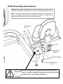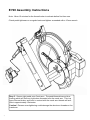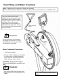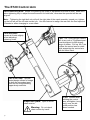
1
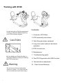
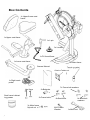
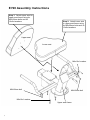
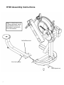
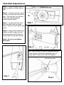
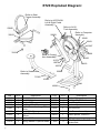
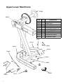
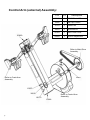
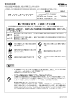
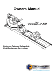
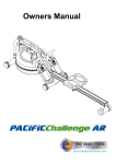
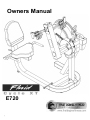
Owners Manual E720 1 Training with E720 Contents As with any piece of fitness equipment, consult a physician before beginning your E720 exercise program. 1. Contents of E720 Box. 2. E720 assembly instructions. CAUTION 3. Tank filling and water treatment. 4. Long term water treatment and basic operation. 5. E720 Control arm. 6. Maintenance. 7. Troubleshooting guide Use two hands and follow all safety instructions whenever raising or lowering the E720 control arm. 8. The E720 Ergometer with USB Function 9. Tank belt drive adjustment. Warning Do not remove feet or hands while crank is in motion. The crank will continue to rotate and could cause injury. 2 10. Parts list and Warranty. Box Contents 1x Upper/Lower seat frame 1x Upper seat frame 1x L-pin 3x Leveler 1x Fill funnel/hose 1x Lower seat frame 1x Main frame Owners Manual Chlorine Tablets x 4 1x Right crank pedal 7x Frame bolt washers Hex Keys Seat frame lubricating grease 2x Batteries 3x Frame bolts 3x Main frame Nylock nut 3 8x Seat bolts M10 Plastic Washer 8x Seat bolt washers 1x Multi-tool E720 Assembly Instructions Step 1: Attach upper seat to upper seat frame using 4x M6x20mm bolts and 4x 16x6xl washers. Step 2: Attach lower seat to upper seat frame using 4x M6x20mm bolts and 4x 16x6xl washers. Upper seat Lower seat M6x16x1 washer M6x20mm bolt M6x20mm bolt M6x16x1 washer Upper seat frame 4 E720 Assembly Instructions Step 3: Attach lower seat to lower mainframe using 4x M10x25mm bolts, 4x M10 Nylock nuts and 8x 21x11x2 washers M10x25mm bolt 21x11x2 washer M10 Nylock nut 5 E720 Assembly Instructions Step 4: Lower upper seat frame onto lower mainframe and secure using 1x M10x25mm bolt, 1x M10 Nylock nut, 3x 21x11x2 washers and L-pin. Note: Tighten the M10x25mm bolt, washers and Nylock until lightly snug only. Over-tightening will prevent the seat from rotating. Use the L-pin to tighten the upper seat frame once rotated into place. M10x25mm bolt L-Pin M10 plastic washer 21x11x2 washer M10 Nylock nut Before installing the upper seat frame onto the lower, use the supplied grease and apply liberally between the two sliding surfaces 6 E720 Assembly Instructions Note: Allow 15 minutes for the thread-locker to activate before first time use. Check pedal tightness on a regular basis and tighten as needed with a 15mm wrench. Step 5: Secure right pedal onto Crank arm. The pedal threads have a blue coating which will feel very tight when threaded onto the crank arm. This is a type of thread locker, and once in contact with the crank arm threads will activate in approximately 15minutes. Caution! Extreme over-tightening could damage the aluminum threads on the crank arm. 7 Tank Filling and Water Treatment Note: A large bucket is required for filling (Not included). In areas where tap water quality is known to be poor, FDF recommends the use of distilled water. Open the tank plug and insert hose into tank (rotating the impeller slightly may be necessary to allow the hose to pass), move the tank adjuster handle to level 20 and begin filling. Do not fill the tank higher than the level indicator on the front of the clear shell. A properly filled tank holds approximately 8 liters of water. Filling hose and funnel WARNING Do not under any circumstances put fingers into the tank. Use the end of the hose to move the impeller should the need arise. Yellow Tank Plug Water Treatment Procedures: 1. Add Chlorine tablet. 2. Enough Chlorine Tablets are supplied for many years of Water treatment. Add a chlorine Tablet whenever the Water appears dirty or cloudy. WARNING: Only use First Degree Fitness Supplied Water treatment tablets. Caution: Use a drop cloth under the tank when filling the tank to avoid damage floor or carpet 8 Note: Lower tank plug is permanently sealed. Long Term Water Treatment and Basic Operation CAUTION Important: Do not fill past the calibration mark as indicated on the tank level sticker or water spillage may occur. See tank filling and water treatment page for details. Long term water treatment: Do not use any water treatment other than the tablets supplied with this machine. For replacement tablets, contact your local First Degree Fitness distributor or visit www.firstdegreefitness.com for distributor locations. Water treatment schedules for the E720 will vary according to the fluid tanks exposure to sunlight but expect 8-12 months near a bright, sunlit window and 2-4 years for a darker location. At the point of finding the water slightly green, add a Chlorine tablet. Remember to wait 72 hours before adding the blue dye as the Chlorine tablet is extremely concentrated. Caution: It is important that a drop cloth be used under the fluid tank whenever the tank plug is opened for water treatment. Resistance: The level of resistance is determined by the level indicator located on the front of the tank. Level one indicates lightest resistance, level twenty represents heaviest resistance. Allow three to four seconds after adjusting resistance handle for the correct resistance level to be achieved. Warning: Removing hands before the crank comes to a complete stop while training can cause injury. The crank is direct drive so as to allow both forward and reverse rotation during workouts. 9 The E720 Control Arm Chain tensioning bolts: Allows for tightening the chain or adjustment from side to side. Make sure when tightening only to adjust the same amount for both bolts, otherwise the sprocket will be misaligned. Note: Tightening the right bolt only will pull the right side of the crank assembly toward you, tightening the left will pull the left side toward you. Use this feature to realign the rear with the front sprocket if needed or when changing to a new chain. Crank arm bolts: Loosen all 8 bolts slightly before adjusting/ tightening chain. T-pin: The T-pin locks the control arm in any one of 72 different positions throughout its 360 degree range of motion. Pull up the T-pin to allow the control arm to rotate while supporting the control arm with the other hand. The E720 Pedal: This patented design allows for usage in both the recumbent position and for sitting/standing upper body workouts. Inspection plate: Open to check chain tension. Warning: Do not check chain tension by hand! 10 L-pin: Loosen when rotating the control arm and tighten (snug only) once the desired position has been reached. Maintenance chart. 11 Item Timeframe Instructions Seat and Frame. Weekly. Wipe down weekly with lint free cloth or more often with heavy club use. PK belt tension. Monthly. Check monthly for signs of slippage. Adjust/ tighten as required. Tank and water treatment. 12 months to 2 years. Follow instructions as specified in the “Water Treatment” section of this manual. Chain drive. Check every 100 hours for correct tension. Open the inspection plate and check tension using a screwdriver or other tool. Tighten as required using chain tensioning bolts located at the end of the control arm. E720 pedals. Tighten weekly using 15mm box wrench (supplied) The pedals should be checked on a regular basis. A loose pedal can cause damage to the crank arm aluminum threads, requiring replacement. Notes Troubleshooting guide: Fault 12 Probable Cause Solution Water changes color or becomes cloudy. Rower is in direct sunlight or has not had water treatment. Change rower location to reduce direct exposure to sunlight. Add water treatment or change tank water as directed in the water treatment section of this manual. Knocking noise from inside the control arm while training, especially when changing directions. Chain requires tightening or adjustment. Open inspection plate located on front of control arm and check tension using a screwdriver or other tool. Use the chain tensioning bolts located at the rear of the control arm to tighten or adjust as needed. The chain should have approx 3mm of slack when properly adjusted. See P.10 for details. Pedals slip during hard training. PK tank belt requires tightening. Remove large inspection plate next to the tank, insert a long tool to push the rear end cap out from the inside, exposing the tank belt tensioning bolt. Loosen tank bolts slightly. Remove upper rubber belt cover to expose the PK belt. Tighten the tank tensioning bolt until the belt is too tight to be twisted from side to side more than 45 degrees by hand. See P.14 for details Pedal is loose (either left or right) and cannot be retightened. Aluminum crank arm threads are stripped. Contact service center for replacement. Then check weekly as recommended. Computer screen illuminates, but does not register when rowing. Loose or failed connection/Sensor gap too wide (see erratic computer display). Check that the computer lead is connected properly. If connected properly check sensor gap. Contact your local service center if this fails to address the problem. The E720 computer does not illuminate after battery installation. Batteries installed incorrectly or need replacing. Reinstall batteries in correct position and try again. If the LCD screen fails to illuminate, try rotating the batteries slightly in the computer. If this fails, contact your local service center. The E720 computer display is erratic/slow while displaying RPM and WATTS Gap between sensor and magnetic ring is too wide. Remove inspection plate and check sensor gap and that magnetic ring is not wobbly. E720 Ergometer. Quick start provides instant workout information. Just start training to activate. You can choose to change UNITS displayed. Note: For complete operational instructions, please refer to the computer manual, which is included with your E720. UNITS displays WATTS, RPM, HR, MPH, Reset Clears data Program Clears current exercise program Level Adjustable from 1-20 13 Set Changes Time, Distance parameters Using the First Degree Fitness USB Interface Description: The USB connectivity now built in to all new models of FDF Console and IPM allow you to enhance your exercise experience by connecting to your home PC or Laptop. Using FDF's own sample applications you can exercise while enjoying your favorite movies. NetAthlon 2 XF for Rowers lets you race with other Internet connected rowers in a Virtual Reality 3D environment or train solo. Setting up USB connectivity 1. Download and Install the USB Device Driver (CDM2xxxx_Setup.exe for 32 and 64 bit Windows 7/Vista/XP) from the FDF Website. 2. Download and Install the Sample USB Applications from the FDF Website (www.firstdegreefitness.com). Download and Install NetAthlon 2 XF for Rowers from http://www.webracing.org/downloads.htm Connecting your - The USB Connector is located on a flying lead at the rear of the IPM, along with the Sensor and Heart Rate Monitor Connectors. - Connect to a Laptop or PC using a standard USB cable, you may need to wait while Windows starts the USB Device Driver. Note: Please refer to computer manual where applicable or for further information refer to our website at www.firstdegreefitness.com 14 Tank Belt Adjustment Step 1: Remove large metal inspection plate as shown above right. Step 2: Using a long tool, push out the rear end cap as pictured right. This will give you access to the tank tensioning bolt (shown bottom right). Step 3: Loosen both the front and rear tank bolts as shown below. Remove front rubber belt cover. Step 4: Using a 6mm Allen key, tighten the belt using the tank tensioning bolt until the belt no longer slips during hard rowing. Note: Do not over tighten tank bolts. Step 2 End Cap Tip: Twist the belt by hand to gauge tightness. Correct tension should be obtained when no longer able to twist more than 45 degrees. Tank tensioning bolt Step 3 Step 4 15 E720 Exploded Diagram: Refer to Seat Frame Assembly Refer to A037/A038 Left & Right Pedal Assembly Refer to A010 Tank Assembly 23045 Refer to Computer Assembly 20850 33913 10040 10043 10067 33915 10066 Refer to Control Arm Assembly 33100 10170 10070 20163 10072 23008 Refer to Seat Frame Assembly 71025 10139 10041 10082 16 P/N 10040 10041 10043 10066 QTY 1 6 6 3 P/N 10170 23008 20163 20850 QTY 6 1 2 1 23045 1 L Pin M10x35 33100 1 Main Frame Assembly 33913 1 Plastic Spacer 10x25x4T 9 Description Bolt M12x140 Nut M10 Nylock Washer M12 End Cap 100x100mm Rubber Cover for Large PK Pulley Screw M4x10 Small Steel Side Cover 100mm Washer M10 10067 2 10070 18 10072 2 10082 10139 Description Washer M4 End Cap 75x75 Rubber Semi Circle Cover Tension Adjustment 33915 1 2 Spring Washer Flywheel Shaft 71025 2 Oil Bushing M10x25mm Main Shaft Rear Bracket Bolt Upper/Lower Mainframe: 20024 20101 P/N QTY Description 20101 10082 20024 33101 73016 10041 23008 20009 1 8 1 1 4 4 1 4 Upper Main Frame Washer M10 Number Decal Lower Main Frame Foot Levelers M8x30 PVC Nut M10 Nylock End Cap 75x75 Rubber Bolt M10x100 20014 1 Right Bottom Frame 30010 1 Left Bottom Frame 10082 30010 20014 10041 33101 10082 10041 10082 20009 17 73016 23008 Control Arm (external) Assembly: 20850 P/N QTY Description 30012 1 DID-25 Chain 178 10066 1 End Cap 100mm 10170 2 Washer M4 10070 2 Screw M4x10 20163 2 Semi Circle Cover 20850 1 Tension Adjustment Refer to Main Drive Assembly Refer to Crank Arm Assembly 20163 10070 30012 Refer to Control Arm Assembly 10170 10066 18 Seat Frame Assembly: 20117 30002 20115 33910 20008 10080 10081 30014 33902 73016 19 10081 10080 P/N QTY Description 20115 1 Seat LS-622 20117 1 Seat Back LS-622 10080 8 Bolt M6x20 10081 8 Washer M6 20008 1 End Cap 75x75 PVC 30014 2 End Cap 30002 2 Handle Grip 33910 1 73016 1 33902 1 Rotating Seat Frame Upper Foot Levelers M8x30 PVC Seat Lower Frame Computer Assembly 10116 10114 P/N QTY Description 50903 13112 10114 10082 10116 10097 10117 1 4 4 1 2 1 Computer Mounting Arm Bushing 20x16x13x10 Washer M10 Bolt M10x60 Nut Dome Head M10 Computer Wiring 1200 10082 10096 1 Bolt M10x70 for Aluminum Rail 10117 50903 1 Computer 10114 10097 10096 13112 10082 20033 20032 Control Arm Assembly 20020 10082 20151 20170 20064 20174 20170 20045 20151 20151 10083 30013 10041 20068 20036 20151 10083 10120 20291 20170 20125 20170 20 P/N QTY 10041 10082 10083 10120 20020 20032 20033 20036 1 1 2 1 1 1 1 1 Description Nut M10 Nylock Washer M10 Bolt M10x20 Screw M6x15 Bolt M10x35 Warning Decal Arm Moving Decal Small Warning Decal P/N QTY 20045 20064 20068 20125 20151 20170 20174 20291 30013 1 1 1 1 4 4 1 1 1 Description L-Pin M12x40 Weight Block T-Pin Plastic Washer 30*6*6 Washer M10 Chain Protection Decal Eccentric Bushing Rotating Arm CXT Decal Main Drive Assembly P/N QTY 10011 1 10012 1 10015 1 10017 10052 1 1 Description P/N QTY Bearing Housing 10083 1 Bolt M10x20 NSK 6005ZZ Bearing 10109 1 Belt 7PK 926mm HUTCHINSON 10138 1 10139 10146 20157 1 1 1 Large PK Transmission Pulley 150mm Key way 7x7x32 Grub Screw M4x6 Description Shaft Washer 30x10.2x3t for Flywheel, Stainless Spring Washer M10 for Impeller Ball Bearing NSK6006ZZ Shaft+Sprocket—E720 10083 10138 10052 10015 10139 10109 10011 10017 10012 10146 20157 Crank Arm Assembly P/N QTY P/N QTY 10082 20020 8 8 Washer M10 Bolt M10x35 Description 20135 20190 1 2 20052 2 Side Bearing Cover 20193 2 20132 20133 20134 2 2 1 France Screw M8x20xP1.0 Crank End Cap Crank-Left 20196 30610 30611 2 1 1 20133 Description Crank-Right Aluminum Block Bearing Housing NSK 6004ZZ Aluminum Block Housing Bearing Wave Washer 20mm Cycle Axle + Cog Right Pedal Assembly 20020 10082 30610 20193 20132 30611 20052 20193 10082 20134 20052 20020 20196 20132 20190 20190 20196 20135 21 20133 A010 Tank Assembly 10207- Tank Plug Yellow 10039 (O Ring 32x3.5-CR) Refer to Tank Back Assembly A006 Sensor Kit Refer to Tank Cover Assembly 70321-Tank Plug Black 10044 Tank Black Outer Cover Ring 10039 (O Ring 32x3.5-CR) 10046 (Large Tank Seal) 10062 Bolt M3x12 A053 Flywheel Assembly E720/820/920 18 x 10035 Bolt M4 Stainless 18 x 10033 Washer 10x4.2x1 Stainless 18 x 10034 Nut M4 Stainless 1x 20136 Flywheel & Shaft 9 x 10047 Impeller Blade 22 A012 Tank Bearing & Seal Kit P/N Description QTY 10012 Bearing NSK 6005ZZ 2 10025 Seal NBR 37x30x8t for Flywheel Shaft 1 10145 Bearing Spacer 30x25.1x20.5mm 1 10186 C Clip RTW-48 1 10186 10012 10012 10145 10025 A013 Tank Back Kit 10186 10012 10012 10145 12300 10025 P/N 23 Description QTY 10012 Bearing NSK 6005ZZ 2 10025 Seal NBR 37x30x8t for Flywheel Shaft 1 10145 Bearing Spacer 30x25.1x20.5mm 1 10186 C Clip RTW-48 1 12300 SMC Tank Back—Gray 1 Tank Cover Assembly 10036 10030 10028 10033 P/N QTY 10027 10028 10030 10032 10033 10034 10035 10036 10059 10162 10184 10193 13345 1 1 1 2 4 4 4 12 1 2 1 1 1 Description Adjuster Handle Shaft Stainless 0.8mm Backing Plate Blue Adjuster PP Tank Ring Adjuster O Ring 12x9x1.5 Stainless Washer 10x4.2x1 Nut M4 Stainless Bolt M4 Stainless Screw M3x20mm for Blue Tank Ring Level Decal 20R M8x10 Grub Screw Tank Level Resistance Handle PU Cover for Resistance Handle PC Tank Cover 10035 10027 10059 10034 10032 10162 13345 P/N QTY Description 10012 2 Bearing NSK6005ZZ 10017 1 Key way 7x7x32 10025 1 NBR 37x30x8t Flywheel Shaft Seal 10026 1 Small PK Transmission Pulley 50mm 10052 10083 1 1 Grub Screw M4x6 M10x20 Bolt 10138 1 Shaft Washer30x10.2x3t Stainless Steel 10139 1 Spring Washer M10 10145 1 Bearing Spacer 30x25.1x20.5 10186 1 C Clip RTW-48 12300 1 SMC Tank Back—Gray 10193 10184 10052 10138 10083 10186 10139 10017 10145 10026 10012 10025 10012 12300 24 See A053 Flywheel Assembly A054 Tank Back and Flywheel Assembly FLUID CYCLE XT (XT-E720) INTERNATIONAL WARRANTY – FULL COMMERCIAL USE This product is designed and constructed for use in any Health Club / Fitness Studio application First Degree Fitness Limited warrants that the Fluid Cycle XT (model FR-E720), purchased from an authorised agent and in its undamaged original packaging, is free from defects in materials and workmanship. First Degree Fitness Limited or its agent will, at their discretion, repair or replace parts that become defective within the warranty period, subject to the specific inclusions and exclusions below. Metal Frame – 10 Year Limited Warranty First Degree Fitness will repair or replace the metal Main Frame should it fail due to any defect in materials or workmanship within 10 years of the original purchase. Warranty does not apply to frame coating. Polycarbonate Tank & Seals – 3 Year Limited Warranty First Degree Fitness will repair or replace the polycarbonate tank or seals should they fail due to any defect in materials or workmanship within 3 years of the original purchase. Mechanical Components (of a non-wearing nature) – 2 Year Limited Warranty First Degree Fitness will repair or replace any mechanical component should it fail due to any defect in materials or workmanship within 2 years of the original purchase. All Other Components (of a wearing nature) – 1 Year Limited Warranty First Degree Fitness will repair or replace any component should it fail due to any defect in materials or workmanship within 1 year of the original purchase. Specific Inclusions Pedals & toe straps Hand grip assemblies Seat All rubber components Computer & speed sensor (excluding replaceable batteries) All drive belts & chains Crank arms All pulleys, rollers & bearings General Exclusions Damage to the finish of any part of the machine Damage due to neglect, abuse, incorrect assembly or use of the machine Any charges for freight or customs clearance associated with the return or dispatch of parts Any damage to or loss of goods during transport of any kind Any labour cost associated with a warranty claim General Conditions The serial number of the machine must be correctly registered with First Degree Fitness Limited or one of its appointed distributors First Degree Fitness Limited reserve the right to examine any part where replacement is claimed under warranty Warranty commences at time of sale but no later than six (6) months from date of original shipment Warranty period applies only to the original purchaser from the date of purchase and is not transferable The product must be returned to your place of purchase in original packaging with transportation, insurance and associated charges paid for by you and risk of loss or damage assumed by you First Degree Fitness makes no other warranties except as stated here and expressly disclaims all warranties not stated in this warranty. Neither First Degree Fitness nor its associates shall be responsible for incidental or consequential damages Manufacturer's warranty automatically commences upon sale of the product to end user or upon the expiration of one (1) year from month of manufacture, whichever occurs first 25