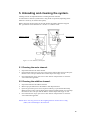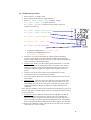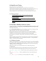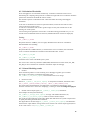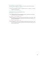
1
GRAVIMAN
Continuous Loss-in-Weight Dosing & Control
System
USER'S MANUAL
EDITION 3.1
July 2004
Sysmetric Ltd claims proprietary rights to the material contained herein. It shall not
be reproduced, disclosed, or used for manufacturing purposes without the express
written permission of Sysmetric Ltd.
Copyright 2002-2004
Sysmetric
P.O.B. 1122 Afula 18550
Israel
Tel: 972-4-6405858
Fax: 972-4-6405855
Email: [email protected]
Contents
1. INTRODUCTION ....................................................................................................................... 4
1.1 FEATURES .................................................................................................................................... 4
1.2 COMPONENTS: .............................................................................................................................. 4
1.3 SAFETY PRECAUTIONS ................................................................................................................. 5
1.4 POWER AND AIR SUPPLIES ........................................................................................................... 5
1.4.1 Power Supply ........................................................................................................................... 5
1.4.2 Compressed Air Supply ............................................................................................................ 5
2. INSTALLATION ........................................................................................................................ 6
2.1 OVERVIEW ................................................................................................................................... 6
2.1.1 Top Flange (holding tank flange)............................................................................................. 6
2.1.2 Bottom Flange .......................................................................................................................... 7
2.2 INSTALLATION AND CHECKING PROCEDURE ................................................................................ 7
3. CONSOLE AND SWITCHES ................................................................................................ 10
3.1 OPERATOR PANEL GRAVIMAN 1 ................................................................................................. 10
4. GRAVIMAN STRUCTURE AND OPERATION ................................................................. 11
4.1 CONTINUOUS GRAVIMAN WEIGH-UNIT....................................................................................... 11
4.1.1 Structure of the Continuous weigh-unit. ................................................................................. 11
4.1.2 Principals of operation........................................................................................................... 11
4.2 CREATING A CONTINUOUS DOSING SYSTEM. ............................................................................. 11
4.2.1 Dosing system Operation. ...................................................................................................... 11
4.3 THE GRAVIMAN AS A CONTROLLER............................................................................................ 12
4.4 LINE OPERATION USING MAIN PLC AND GRAVIMAN/S. ............................................................... 12
4.4.1 Manual mode operation ......................................................................................................... 13
4.4.2 Auto mode operation .............................................................................................................. 13
5. UNLOADING AND CLEANING THE SYSTEM. ................................................................ 14
5.1 CLEANING THE MAIN CHANNEL. ................................................................................................. 14
5.2 CLEANING THE ADDITIVE CHANNEL. .......................................................................................... 14
6. MAINTENANCE AND SERVICING. .................................................................................... 15
6.1 TEACHING ADDITIVE MATERIAL PARAMETERS (GRAVIMAN #2). ................................................ 15
6.2 TUNING THE MATERIAL PROXIMITY SENSORS. ............................................................................ 15
6.2.1 Tuning procedure: .................................................................................................................. 15
6.3 LOAD-CELL CALIBRATION. ........................................................................................................ 16
6.3.1 Calibration procedure. ........................................................................................................... 17
6.4 AMPLIFIER CARD TUNING. ......................................................................................................... 18
6.4.1 Tuning procedure. .................................................................................................................. 18
6.5 GRAVIMAN, ‘MODELING’ METHOD OF CONTROL. ....................................................................... 18
6.5.1 Filling the Graviman. ............................................................................................................. 18
6.5.2 Calculation Thresholds. ......................................................................................................... 19
6.5.3 Control Modeling results. ...................................................................................................... 19
2
7. TROUBLESHOOTING............................................................................................................ 21
7.1 ALARMS ..................................................................................................................................... 21
7.1.1 EX_1_LOW_material_level_IN_hopper_grav_1 .................................................................. 21
7.1.2 EX_1_LOW_material_level_IN_grav_1, EX_1_NO_material_IN_grav_1 .......................... 21
7.1.3 EX_1_Screw_Capacity_1_too_high ..................................................................................... 22
7.1.4 EX_1_Screw_Capacity_1_too_low ....................................................................................... 22
7.1.5 EX_1_grav_1_WEIGHINGerror .......................................................................................... 22
7.1.6 EX_1_screw_2_over_current ................................................................................................ 23
7.1.7 EX_1_LOW_PLC_battery ..................................................................................................... 23
7.1.8 EX_1_on_GRAV_1_off......................................................................................................... 23
3
1. Introduction
The Graviman Continuous-Dosing Unit is used to keep track of raw-material flow using a
loss-in-weight method. With this method, the rate of weight reduction in the weighing-bucket
is consistently monitored.
It is possible to integrate a number of weigh modules with an ‘Additive feeder gravimetric
control’ in order to realize a mixing / blending facility.
The weighing-bucket is filled automatically.
System Control is based on an OMRON CQM1H CPU51 industrial programmable logic
controller.
An advanced method of controlling named ‘Control Modeling Method’ (as opposed to regular
methods such as PID etc.) is employed by the Graviman in order to control the speed of each
screw feeder in the system.
The ‘Control Modeling Method’ boasts many advantages: high accuracy, immunity to many
kinds of disturbance, non-linear control and very good stability.
1.1 Features
• Semi-automatic calibration
• A combination of hardware and software signal
conditioning and filtering ensures shock and vibration
resistant operation.
• No need for tuning or setup when replacing raw materials.
• One year warranty on parts (Sysmetric conditions).
1.2 Components:
Description of two combined Graviman units with a connective screw-feeder. Used when
blending of materials is required:
1.
Main weighing unit.
2.
Holding tank level sensor.
3.
Pneumatic shutter.
4.
Load Cell.
5.
Weighing-bucket.
6.
Additive weighing unit.
7.
Additive holding tank level sensor.
8.
Additive Load Cell.
9.
Additive Pneumatic shutter.
10. Additive Weighing-bucket.
11. Screw-feeder.
12. Center pipe.
Figure r1-1 General Component Layout
4
1.3 Safety Precautions
•
CHECKING AND REPLACEMENT OF ELECTRICAL
PARTS MUST BE PERFORMED BY QUALIFIED
PERSONNEL ONLY!
•
DISCONNECT THE ELECTRICAL POWER SUPPLY
BEFORE SERVICING.
•
DISCONNECT THE AIR SUPPLY BEFORE
SERVICING PNEUMATICS.
ATTENTION: The pneumatic shutters operate
automatically and may change position
without warning!
•
The electrical cabinet contains an electrical potential of
220VAC. The key to these doors should be in the
possession of service personnel only.
1.4 Power and Air Supplies
1.4.1 Power Supply
Single-phase 220VAC 50/60Hz 1Amp electrical power supply.
1.4.2 Compressed Air Supply
Dry non-lubricated compressed air at 6 bars of pressure.
5
2. Installation
2.1 Overview
The following is an overview of the steps required to install the Graviman unit and
check that it is working properly. The description assumes some prior technical
knowledge. For more information, contact Sysmetric Ltd.
When installing this system, a few basic rules must be observed:
Leave all service hatches clear of obstruction.
The unit has to be positioned firmly on the feed throat of the production
machine.
The unit has to be guarded against sources of mechanical damage (forklifts
etc.).
All conveyors of system materials have to be firmly installed.
The system is composed of several components; the installation procedure consists of laying
them out, checking them, connecting them to the power and air supplies and then joining them
to each other and to the production machine.
Installation procedures:
Unpacking the Graviman components.
Checking the weighing unit of each channel for damage on delivery.
Mounting and calibrating the Load Cells.
Mounting the holding tanks.
Mounting the optional material loaders.
Mounting the Graviman system onto the throat of the production machine.
2.1.1 Top Flange (holding tank flange)
Suction loaders and other material feeding equipment can be attached to this flange using
suitable adapters if needed.
6
2.1.2 Bottom Flange
The flange should be bolted to the throat of the production machine, usually with a suitable
adapter.
An optional magnet chamber with a slide-gate, a drainage outlet and a custom made bottom
flange for the machine, can be supplied.
2.2 Installation and Checking procedure
1.
Unpack the Graviman components and lay them out in the order that they
will be when assembled. Check for missing components.
2.
Visually check all components for delivery damage, pay special attention to
the load cells.
For each channel:
3.
Place the dispensing unit on the floor, standing on its bottom flange.
4.
Mount the load-cell to the external chassis using the bolts on the load-cell.
The load-cell sits on a 6mm thick spacing plate. Make sure the weighing
hopper is at the middle of the chassis and isn’t touching anything. Tighten
the bolts.
5.
Mount the holding tank extension (with the material level sensor) if it has
been packed separately.
6.
Mount the (optional) material loader to the top flange (refer to section 2.1.1)
7.
Supply air pressure (dry air, 5-7 bar) using 6mm hose.
7
8.
Make sure the pneumatic valve is Closed (an electrical signal to the solenoid
should open the valve).
9.
Check weighing bucket (load cell) calibration (refer to section 6.2).
General:
10. Mount the Graviman unit in position using the bottom flange and a suitable
adapter (refer to section 2.1.2).
11. Connect 230V 50/60Hz single-phase mains power to the N, L and Ground
terminals in the junction box. Make sure the power line is suitably protected.
12. Connect All plc to CLK network
Plc
Node
number in
Clk network
Dm6000
Extruder
number
Line main
plc
10
Not used
Ex_A/Ex_1
11
1
Ex_B/Ex_2
12
2
Ex_C/Ex_3
13
3
Ex_D/Ex_4
14
4
Ex_E/Ex_5
15
5
Ex_F/Ex_6
16
6
Ex_G/Ex_7
17
7
Vacuum Plc
20
Not used
For full detail see CLK manual (PDF)
8
CLK CONFIGURATION
dm6000 is an index number for the plc program in order to transfer the graviman registers to
the data link area.
9
3. Console and Switches
3.1 Operator Panel graviman 1
Graviman 1
The Operator Panel contains the following components:
1. Graviman 1 switch <open><close><auto>
•
<open> the valve is always open (for system drainage).
•
<close> the valve is always close (also for calibration mode).
•
<Auto> auto mode (normal operation)
2. Graviman 2 switch <open><close><auto> same as graviman 1
3. <Teach> push bottom (fast parameter teaching of new material)
Graviman 2 panel
10
4. Graviman Structure and Operation
The Graviman is flexible device suitable for several uses: A continuous weighing system,
dosing system, weight control system or as a combination of any of these.
4.1 Continuous Graviman weigh-unit.
The Graviman weigh-unit can be operated in one of two ways:
1.
As a single unit fixed straight on the feed throat of the production machine,
working as a continuous weight controller with one type of raw material.
2.
As a combined dosing and weigh-controlling unit with a number of
Graviman weigh modules. A central unit doses straight into the main outlet
pipe while secondary additive units use screw feeders to dose to the outlet
pipe. The central unit calculates the desired throughput while the secondary
units adjust their screw feeder outputs accordingly.
4.1.1 Structure of the Continuous weighing-unit.
The Graviman Continuous weigh-unit constitutes the heart of the system. It provides precise
loss-in-weight information from the weighing-bucket to the PLC controller. The unit has been
designed to protect the bucket from all kinds of disturbances.
The weigh-unit is made up of three main components:
1.
Outer housing.
2.
Pneumatic shutter.
3.
Weighing-bucket with Load Cell.
•
•
•
The housing protects the weighing process from being disturbed in any way.
Two service hatches in the housing facilitate periodic checking and cleaning of
the bucket.
The shutter controls weighing-bucket filling.
The unit continuously tracks the material flowing through the system.
4.1.2 Principles of operation.
At startup, the system controller (PLC) checks the amount of material in the weighing-bucket
and fills it up as needed by opening the pneumatic shutter.
The weigh-unit provides the PLC with continuous weight readout.
During work, when the material weight in the weighing-bucket is reduced to a predetermined
minimum level, the pneumatic shutter is opened and the bucket is refilled.
The PLC calculates throughput by using weight data and screw-feeder-RPM from the
production machine.
4.2 Creating a Continuous Dosing System.
Linking several Graviman units and feeder screws, to a central Graviman unit and pipe,
creates a continuous dosing system.
4.2.1 Dosing system Operation.
The system controller calculates the throughput for each screw feeder using data from the
continuous weigh-unit. Each screw feeder is fixed to a Graviman weigh-unit making closed
11
loop control a possibility. The central system controller uses loss-in-weight and screw feeder
RPM in order to calculate the percentage of screw rotation for each channel.
4.2.1.1 Screw feeder compatibility.
Each screw feeder in the dosing system has to be able to cope with its intended throughput.
The throughput for each channel is a function of batch composition (material density) and
system throughput.
4.3 The Graviman as a controller.
The Graviman system can perform different control jobs on demand:
1.
Production machine throughput control – The machine operator enters the requested
throughput in Kg/hr, The system will vary machine screw revolutions as needed.
2.
Product weight control (weight per meter) - The machine operator enters the
requested weight per meter. The system will control machine screw revolutions or
line speed, in order to maintain the product’s weight per meter.
3.
Layer control – Each extruder in the production line contributes its proportion of
material as dictated by the product.
Note: The systems are controlled using data tables transfered by the CLK. The following
example words are for the first extruder A. The extruder index numbers (at left ) differes from
extruder to extruder. Take care to choose the appropriate paramters when servicing each
system in your line.
4.4 Line Operation using main plc and Graviman/s.
Each Extruder uses
2 write chanel for control (orange)
for example EX_1_GRAV_1_Control_word CHANNEL
2000
100 Write Data memory (violtet)
for example EX_1_GRAV_1_SetdR
INT
D4000
INT
D4700
100 Read only data memory
for example EX_1_GRAV_1_Last_dR
2 read chanel for and alarm
for exmple EX_1_GRAV_1_Alarm_word
CHANNEL
2014
refer to attached CX example program for address details
The system has 2 modes of operation:
a)
Manual mode where the system measures the capacity of extruder.
b) Automatic mode where the system dictates the required RPM for the desired
capacity.
12
4.4.1 Manual mode operation
In manual mode the extruder RPM is set by the user. The Graviman monitors the capacity.
The Graviman switch to should always be in <auto> position.
The values of EX_1_ON, EX_1_GRAV_1_RPM_AT_10V and EX_1_GRAV_1_Act_RPM
should be always update to reflect system position.
Turn on the bit EX_1_Manual_mode.
Refer to section 6 for full detail.
EX_1_Actual_capacity will show the total capacity of extruder (main grav and grav 2)
Enter the desired percentage of the additive to EX_1_GRAV_2_Set_Percentage
The percentage of the main material will adjust itself automatically to complement to 100%.
The accumulators EX_1_GRAV_1_Accumulator and EX_1_GRAV_2_Accumulator will
show material amounts. To reset Accumulators turn on the bits EX_1_GRAV_1_Reset_Total
and / or EX_1_GRAV_2_Reset_Total for one second.
4.4.2 Auto mode operation
In Auto mode the Graviman receives the desired capacity through the CLK and sends back the
set RPM.
Enter the desired capacity to EX_1_GRAV_1_Set_Capacity
Enter the desired percentage of the colour channel material (GRAV#2)
EX_1_GRAV_2_Set_Percentage
Turn off the bit EX_1_Manual_mode
Copy the EX_1_GRAV_1_Set_RPM to extruder drive to get to the desired capacity.
13
5. Unloading and cleaning the system.
Cleaning must be accomplished before switching between materials.
It is advisable to clean the system before a long break in operation (depending on the
material’s sensitivity to moisture absorption).
Before emptying the Graviman, all external feeders and loaders should be stopped.
The <graviman> switch should be on <AUTO> or <OPEN> mode.
Additive channel
Main channel
Figure r5-1 Two channel system layout
5.1 Cleaning the main channel.
1.
Stop material feed to the main channel.
2.
Open material drain valve (not part of the system). When bucket level will drop the
material valve will open and the main channel hoper will empty as well.
3.
Once material flow stops, open service door and use compressed air to clean the
valve and bucket apparatus.
5.2 Cleaning the additive channel.
1.
Stop material feed to the additive channel.
2.
Mount a proper bucket below the additive drain flap and motor.
3.
Open one gear motor pivot screw, flip motor sideways, open material drain flap.
Material will now flow into the drain bucket. When weighing bucket level will drop
the material valve will open and the additive channel hoper will empty as well.
4.
Once material flow stops, open service door and use compressed air to clean the
valve and bucket apparatus.
NOTE: Don’t exert any pressure on the weighing-buckets. Pressure above 15Kg
(10lbs) will cause damage to the load cells.
14
6. Maintenance and Servicing.
Each material has several parameters in the system. The main channel parameters are set by
the user. Additive parameters are lerned by the system automatically by the channel at teach
mode. This allows the user to change material or screw type easily.
6.1 Teaching additive material parameters (graviman #2).
1.
Open additive middle drain (4 screws) and mount a box under the opening.
2.
Make sure the cleaning and test covers are closed and additive is present.
3.
Move Graviman #2 selector to <CLOSE> position.
4.
Press the orange push button for 3 seconds until button lamp blinks.
The screw starts turning at full capacity and measures the capacity per revolution, this value is
displayed in the EX_1_GRAV_2_Last_Screw_Capacity - Operator can monitor it to make
sure the value is steady.
5.
After about 30-60 seconds procedure will end. The
EX_1_GRAV_2_S_D_Screw_Capacity (Standard deviation) value will drop
below 8% and the screw will stop rotating.
6.
If the operator wishes to end it earlier the orange push button should be
pressed once more.
6.2 Tuning the material proximity sensors.
These capacitive sensors alarm when the level of material drops. They are connected to the
PLC as Normally Closed contact. This means that they activate the input to the PLC when the
sensor isn’t sensing material. The LED on the sensor’s rear goes ON whenever the sensor
detects material.
Sensor sensitivity is calibrated using the small screw on the rear. The screw is covered by a
plastic cap, which should be removed first.
Turning the screw clockwise will increase sensor sensitivity, and counter-clockwise will
decrease sensitivity.
Note:
It is a common error to turn the cap instead of turning the calibration screw. This is
because the cap has the shape of a screw itself. Be sure to pull out the cap first.
6.2.1 Tuning procedure:
1.
Make sure the sensor doesn’t have any raw material in its vicinity.
2.
Increase sensor sensitivity until the LED turns on.
3.
Slowly decrease sensitivity until it turns off.
4.
Decrease sensitivity by another half a turn.
15
6.3 Load-Cell calibration.
Calibration should be checked after replacement of any part involved in weighing (Load-cell,
amplifier or analog card).
It is recommended that a calibration be performed on a regular basis as scheduled by the
customer.
Each weigh-unit must be calibrated separately.
During the calibration procedure, three tests are performed:
• Hysterasis Test: Ensures that there’s no friction in the load-cell and weighing-bucket.
• Calibration Test: Ensures the correct ratio used by the unit to convert from the loadcell voltage output to the actual displayed weight.
• Linearity Test: Ensures the linearity of the load-cell.
There are two important considerations to be taken into account:
1.
Each of these tests must be performed in order to ensure proper functioning of the
unit.
2.
There’s no point in performing a test if the unit failed a previous test. For example, if
the unit fails the hysterasis test then there’s no point in performing the calibration
test, because there’s some friction (mechanical or otherwise) that is preventing the
load-cell from working properly.
16
6.3.1 Calibration procedure.
1.
Move selector to <CLOSE> mode.
2.
Empty material from bucket as explauined above.
3.
Read EX_1_GRAV_1_Hopper_voltage (Amplifier voltage),
EX_1_GRAV_1_Hopper_weight (Mass) and enter
EX_1_GRAV_1_Ref_Mass (calibration reference mass value) (see
example screen below).
EX_1_GRAV_1_Hopper_voltage INT D4712
EX_1_GRAV_1_Hopper_weight INT D4711
EX_1_GRAV_1_Calibration BOOL2000.05
EX_1_GRAV_1_Tare
BOOL 2000.0
EX_1_GRAV_1_Ref_Mass INT D4007
• To perform [TARE] turn on EX_1_GRAV_1_Tare
• To perform [CALIBRATION] turn on
EX_1_GRAV_1_Calibration
4.
When there’s no load on the bucket, the voltage displayed should be
0.0±0.2V. If the display exceeds this tolerance, make sure the weighingbucket is empty and has no forces exerted on it. When the bucket is free and
empty perform the calibration procedure.
5.
Hysterasis test: Gently press the weighing-bucket and release it. The value
in “Act” should increase and then drop back to its original value. Allow a
tolerance of 2 grams. Gently pull the bucket up and let go of it, the value
should drop momentarily below its original value, and then return (±2
grams).
6.
A failure in the hysterasis test means the weighing-bucket is being
obstructed in some way. Find and fix the problem.
7.
Wait 10 seconds for the bucket to stabilize. Perform action tare to zero the
mass reading.
8.
Calibration test: Open the service door and place a reference mass on the
bucket tray. It is good to use reference mass of at least 1500gr. The “Act”
value should show the correct value (allow a tolerance of 2 grams). If the
weight reported doesn’t match, recalibration is needed. Perform action
calibration.
Note: After first calibration, the process should always show that the system is ok.
If error is detected, it is best to find the reason for it (usually mechanical) and not
to just to recalibrate.
9.
Linearity test: Place a different weight on the tray and make sure that the
“Act” value matches that of the new weight. This can be repeated with
additional reference weights to verify the whole range. If the range is not
linear, the weigh-unit (bucket, load-cell or amplifier) must be checked and
fixed. Calibration should be performed only with the biggest reference mass.
10. Remove the calibration weight, and close the service door. Turn the selector
switch back to <AUTO> position.
17
6.4 Amplifier card Tuning.
Each weigh-unit has its own amplifier card.
Amplifier cards can be found in the junction boxes adjacent to the weigh-units.
Tuning should be attempted only after the replacement of the load cell or the amplifier card
itself. The cause of any other weight digression should be found and dealt with.
Voltage irregularities are usually caused by a loose or dirty component in the load cell.
6.4.1 Tuning procedure.
1.
Connect a Digital-Volt-Meter (DVM) to the output terminals of the
amplifier card (red & black wires).
2.
Select the Vdc range.
3.
An empty weighing-bucket should read 0Vdc (±100mV). If not, adjust by
turning the ZERO trim pot.
4.
Open the service hatch and place a reference weight on the special tray. The
output should read 1Vdc for every 0.5Kg of weight. Adjust using the CAL
trim pot.
6.5 Graviman, ‘Modeling’ method of control.
An advanced method of controlling named ‘Control Modeling Method’ (as opposed to regular
methods such as PID etc.) is employed by the Graviman in order to control the speed of each
screw feeder in the system.
The ‘Control Modeling Method’ boasts many advantages: high accuracy, immunity to many
kinds of disturbance, non-linear control and very good stability.
During normal operation, the Graviman samples and ‘learns’ the angular throughput
(throughput per rotation) for each screw feeder in the system. It uses this information to
calculate the screw speeds needed to yield appropriate proportional throughputs.
The learning process is gradual. Relevant data is processed and selected using statistical
algorithms.
Dedicated parameters allow adjustments and calibrations to be performed. Each channel has a
number monitoring parameters. ‘Ex_1 is the depiction of Extruder ‘1’ in the parammeters
(replace ‘1’ with the true Extruder number).
6.5.1 Filling the Graviman.
Material in the weighing-bucket is constantly decreased in relation to screw feeder throughput.
The pneumatic shutter is automatically opened in order to refill the bucket every time material
dwindles (1.5Kg). All calculations are suspended during the fill cycle because the measured
weight doesn’t reflect screw throughput.
During the critical fill cycle, the system controls the screw speed using previously
accumulated data.
The data from the beginning of a fill cycle and the data from the end of a fill cycle should
allow at least 30 seconds of uninterrupted operation between one fill cycle to the next.
EX_1_GRAV_1_Hopper_weight - Continuous hopper (bucket) weight display (resolution =
1g).
EX_1_GRAV_1_Close_Leve - End of weighing-bucket fill cycle. Recommended value:
3.000Kg.
EX_1_GRAV_1_fill_level - Start of fill cycle. Recommended value: 1.500Kg.
18
6.5.2 Calculation Thresholds.
Screw throughput is not calculated continuously. A number of statistical tools assist in
determining the ‘sampling timing and rate’ of material weight and screw revolutions needed to
perform the calculation and build the control ‘model’.
The machine operator can determine basic values that affect the timing of throughput
calculation.
A fast rate of calculation will result in rapid assessments, but the outcome will be erratic
owing to the nature of the process.
A slow rate of calculation will result in good average accuracy but will fall short on the
learning rate of the system.
Correct tuning of the parameters will result in a calculation being performed every 3 to 10
seconds with a standard-deviation of about 2% (Standard-deviation results are displayed).
Setting:
EX_1_GRAV_1_SetdM
Set partial derivative of Mass, (loss in weight). Minimum-mass factor for calculations.
Recommended value 0,050Kg.
EX_1_GRAV_1_SetdR
Set partial derivative of Revolutions, (a constant times screw revolutions). Sets minimum
screw revolutions threshold for calculation. Recommended value 10 units.
EX_1_GRAV_1_Last_dR
EX_1_GRAV_1_Last_dM
Actual derivative values calculated by the system.
The correct ratio of the two parameters (SdM; SdR) should result in actual values (last_dM;
last_dR) just above the derived ‘calculation’ threshold. Adjust accordingly.
6.5.3 Control Modeling results.
1.
General
Each calculation produces a result of dosing screw throughput (grams) per revolution.
The result is converted to a normalized percentage scale
EX_1_GRAV_1_Last_Screw_Capacity based on full-scale screw ratings.
2.
Erroneous result:
Result EX_1_GRAV_1_Last_Screw_Capacity is compared to minimum, maximum values
(EX_1_GRAV_1_MAX_SCREW_CAP EX_1_GRAV_1_MIN_SCREW_CAP).
This check allows disqualification of samples that occurred during disturbances. If the
deviation continues for 3 consecutive samplings, a warning is issued: Low/High throughput!
3. Normal control output signal (EX_1_GRAV_1_Control_dev) calculation:
Good samples are analyzed statistically.
EX_1_GRAV_1_Average_Screw_Capacity Average and standard deviation (s.d.)
EX_1_GRAV_1_S_D_Screw_Capacity results are used in further analysis.
The results are passed through a high order digital filter and allows the system to adjust itself
to rapidly fluctuating material flow conditions.
The digital filter is the final stage EX_1_GRAV_1_Control_Screw_Capacity. The difference
between filter output and the average of the last 10 results is the control output signal (known
as the ‘control error’: c.e.). EX_1_GRAV_1_Control_dev
19
EX_1_GRAV_1_Last_Screw_Capacity
Last result screw throughput, in: Grams per ‘percentage of full-scale screw speed’.
EX_1_GRAV_1_Average_Screw_Capacity
Average screw throughput of the last ten legitimate results, in: Grams per ‘percentage
of full-scale screw speed’.
EX_1_GRAV_1_S_D_Screw_Capacity
Standard deviation of the last ten legitimate results.
EX_1_GRAV_1_Control_dev
Control signal, should not exceed one standard deviation. Should the system digress
occasionally, please consult ‘Sysmetric’.
EX_1_GRAV_1_MAX_SCREW_CAP
Typical maximum for a given screw and material. This value has to be learned: – Run
the screw without interruption and collect some typical results, multiply by 1.5
and type onto the screen.
EX_1_GRAV_1_MIN_SCREW_CAP
Typical minimum for a given screw and material. This value has to be learned: – Run
the screw without interruption and collect some typical results, multiply by 0.75
and type onto the screen.
20
7. Troubleshooting
During alarm conditions suitable bit will turn on.
Multiple alarms can be displayed.
Each Graviman has alarm word
EX_1_GRAV_1_Alarm_word
EX_1_GRAV_2_Alarm_word
The alarm bit will be on as long as the alarm is active.
7.1 Alarms
7.1.1 EX_1_LOW_material_level_IN_hopper_grav_1
Meaning:
Material level in the holding tank is underneath the sensor
Possible causes:
1. Tank loader malfunction.
2.
Source silo is empty.
3.
Tank sensor faulty.
Action:
1.
Check loader and pipes. Is the loader switched on? Is there a blockage or
leakage?
2.
Check vacuum motor. Isolating switch off? Tripped overload?
3.
Check source silo for lack of material or blockage. Is the material moist?
4.
Make sure the air pressure is within 6-8bars.
5.
Check and tune the tank sensor (see section 6.1).
7.1.2 EX_1_LOW_material_level_IN_grav_1, EX_1_NO_material_IN_grav_1
Meaning:
No material in the weighing-bucket.
Possible causes:
1.
Tank loader malfunction.
2.
Source silo is empty.
3.
Tank sensor faulty.
Action:
1.
Check loader and pipes. Is the loader switched on? Is there a blockage or a
leak?
2.
Check vacuum motor. Isolating switch off? Tripped overload?
3.
Check source silo for lack of material or blockage. Is the material moist?
4.
Check compressed air pressure, should be 6-8bars.
5.
Check and tune the tank sensor.
21
7.1.3 EX_1_Screw_Capacity_1_too_high
Meaning:
Channel ‘1’ Screw-feeder output is too high.
Possible causes:
1.
Weight per volume of a new material is high compared to the previous
material.
2.
Screw feeder is the wrong size.
3.
Malfunction in the screw-feeder speed controller.
Action:
1.
Tune the ‘modeling control’.
2.
Replace the screw. Retune the ‘modeling control’.
3.
Call a qualified technician.
7.1.4 EX_1_Screw_Capacity_1_too_low
Meaning:
Channel ‘1’ Screw-feeder output is too low.
Possible causes:
1.
Weight per volume of a new material is low compared to the previous
material.
2.
Screw feeder is the wrong size.
3.
Malfunction in the screw-feeder speed controller.
4.
Dirty or worn components in the motor, screw or shaft.
Action:
1.
Tune the ‘modeling control’.
2.
Replace the screw. Retune the ‘modeling control’.
3.
Call a qualified technician.
4.
Check the overload lamp on the speed controller. Reset by disconnecting the
power for 5 seconds.
5.
Clean the screw and screw motor. Check the bearings and other parts for
excessive wear.
7.1.5 EX_1_grav_1_WEIGHINGerror
Meaning:
Channel ‘1’ reporting excessive weight in the weighing bucket.
Possible causes:
1.
Material overflow in the weighing bucket.
2.
Load cell dirty or out of calibration.
Action:
1.
Check compressed air pressure, should be 6-8bars.
2.
Clean the load cell as needed.
3.
Calibrate the load cell.
22
7.1.6 EX_1_screw_2_over_current
Meaning:
Channel ‘2’ reporting screw-feeder speed controller malfunction.
Possible causes:
1.
Material overflow in the holding tank. Make sure the system is not flooding
the tank with material.
Action:
1.
Check and tune the tank sensor (see section 6.1).
2.
Call a qualified technician.
7.1.7 EX_1_LOW_PLC_battery
Meaning:
PLC memory backup battery is low on charge. If it is not replaced in time, the PLC could lose
its program and memory contents.
Action:
1.
Replace the PLC memory backup battery
7.1.8 EX_1_on_GRAV_1_off
Meaning:
The extruder is working and the gravimen selector switch <close>
Possible causes:
1. graviman selector switch is <close>
2.
the extruder is off but EX_1_ON bit is on
Action:
1. turn the graviman switch to <auto>
23
8. Spare Part List
When ordering spare parts specify the Item number, Catalog number and description.
Consult Sysmetric regarding spare parts not shown here
Item
2
3
4a
4b
Catalog Number
E1
P3
E1010x15
E1040x15
P101
E-CQM51CPU-NL
CQM1 ID212
CQM OD212
E-NT11S-SF12
P200
Description
30mm Capacity switch, 24V DC (sometimes located higher then shown)
Air Cylinder 16x50 ISO, Filing Valve
Load Cell 15kg Tedea 1010 (old – high profile 62mm)
Load Cell 15kg Tedea 1042 (new – low profile 40mm)
Solenoid Valve 24V DC 5x2 1/8"
CPU for CQM PLC
Input CQM card
Output CQM card
Omron NT11 screen
Air regulator with filter
24