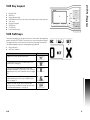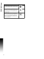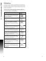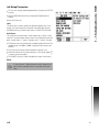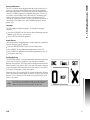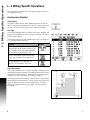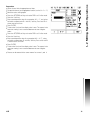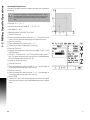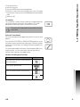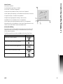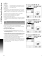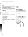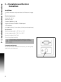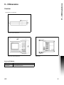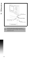
1
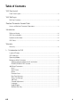
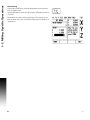
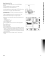
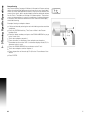
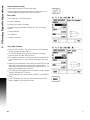
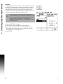
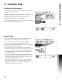
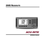
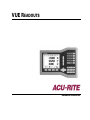
VUE READOUTS REFERENCE MANUAL VUE Key Layout VUE Key Layout 1 2 3 4 5 6 7 8 9 Display Aera Soft keys Page Indicator light UP/DOWN arrow keys are also used to adjust the screen contrast Axis Keys Numeric Keypad ENTER key CLEAR key Hard function keys 61 1 51 71 91 31 21 81 41 VUE Soft keys There are two pages of soft key functions to select from the operating modes. Use the LEFT/RIGHT arrow keys to cursor through each page. The page indicator in the Status Bar will show the page orientation. The darkened page indicates the page being displayed. 1 2 1 21 Page Indicator Set Zero Indicator Soft Key function Soft key Opens on-screen Help Instructions. Toggles between Inch, and Millimeter units (see "Units" on page 5). This soft key toggles between radius and diameter displays. This function is for Turning applications only (see "Diameter Axes" on page 6). Toggles between Set/Zero functions. Used with individual axis keys (see "Set/Zero Soft Key" on page 7). Opens the Job Setup menu and provides access to the Installation Setup soft key (see "Job Setup Parameters" on page 5). VUE iii VUE Soft keys Soft Key function Press when ready to identify a reference mark (see "ENABLE/DISABLE REF function" on page 4). Opens the Tool Table. See "Tool Table" on page 8 for Milling. See "Tool Table" on page 22 for Turning. The tool key is a soft key for the one axis readout only. Opens the Datum form to set the datum for each axis. See "Datum Setting" on page 10 for Milling. See "Datum Setting" on page 24 for Turning. The datum key is a soft key for the one axis readout only. iv Soft key Readout Parameter Access Code Readout Parameter Access Code An access code must be entered before machine-related installation parameters can be set or changed. This prevents inadvertent adjustments to the installation setup parameters. IMPORTANT! The access code is 8891. Access to Machine Parameter Operations Refer to the Setup section also. Begin by pressing the SETUP soft key. Press the soft key INSTALLATION SETUP. Press the access code numbers 8891 using the numeric key pad. Press the ENTER key The readout is now ready for machine parameter setting operations IMPORTANT! Supervisors may wish to remove this page from the Reference Manual after initially setting up the readout system. Retain in a safe place for future use. VUE v vi Readout Parameter Access Code Introduction Introduction Software Version The software version is shown on the initial power up screen. This User's Manual covers the functions of the VUE for both milling and turning applications. Operational information is arranged in three sections: General Operations, Mill Specific Operations and Turn Specific Operations. VUE DRO axis availability. The VUE DRO is available in one, two, and three axis form. The 3 axis VUE DRO is used through out this manual for illustration and description of function keys. Symbols within Notes Every note is marked with a symbol on the left indicating to the operator the type and/or potential severity of the note. General Information e.g. on the behavior of the VUE. Warning e.g. when a special tool is required for a function. Caution - Risk of electric shock e.g. when opening a housing. VUE Fonts The following shows how the soft, and hard keys are represented within the text of this manual: Soft keys - SETUP soft key Hard keys - ENTER hard key VUE vii viii VUE Fonts Warranty For additional information, please go to www.acu-rite.com. VUE ix x Table of Contents VUE Key Layout Front Panel Layout ................................................................................................... iii VUE Soft keys Soft Key Functions................................................................................................... iii Readout Parameter Access Code Access to Machine Parameter Operations ...............................................................v Introduction Software Version .................................................................................................... vii VUE Axis availability ................................................................................................ vii Symbols within Notes............................................................................................. vii VUE Fonts............................................................................................................... vii Warranty Warranty ..................................................................................................................ix I – 1 Introduction to VUE Layout of Screen...................................................................................................... 1 VUE Hard Keys ........................................................................................................ 2 Operating Modes ..................................................................................................... 3 Reference Mark Evaluation...................................................................................... 3 Working without reference mark evaluation....................................................... 4 ENABLE/DISABLE REF function......................................................................... 4 Job Setup Parameters ............................................................................................. 5 Units.................................................................................................................... 5 Scale Factor ........................................................................................................ 5 Mirror .................................................................................................................. 5 Diameter Axes .................................................................................................... 6 Near Zero Warning.............................................................................................. 6 Status Bar Settings ............................................................................................. 6 Job Clock ............................................................................................................ 6 Console Adjustment ........................................................................................... 7 Language ............................................................................................................ 7 Import/Export ...................................................................................................... 7 Set/Zero Soft Key................................................................................................ 7 VUE xi I – 2 Milling Specific Operations Key Functions Detailed ............................................................................................ 8 Tool Hard Key ..................................................................................................... 8 Tool Table ........................................................................................................... 8 Tool Compensation............................................................................................. 8 Sign for the length difference ΔL........................................................................ 9 Calling the Tool from the Tool Table ................................................................... 9 Datum Setting................................................................................................... 10 Datum Setting with a Tool ................................................................................ 11 Presets.............................................................................................................. 12 Absolute Distance Preset ................................................................................. 12 Preparation:....................................................................................................... 13 Incremental Distance Preset ............................................................................ 14 1/2 Hard Key ..................................................................................................... 15 Circle, and Linear Pattern................................................................................. 15 Functions for milling pattern soft keys ............................................................. 15 Circle pattern .................................................................................................... 16 Linear Pattern ................................................................................................... 17 Incline & Arc Milling .......................................................................................... 17 Incline Milling .................................................................................................... 18 Arc Milling ......................................................................................................... 20 I – 3 Turning Specific Operations Tool Table ......................................................................................................... 22 Tool Display Icon............................................................................................... 22 Setting Tool Offsets with Tool/Set ................................................................... 22 Setting Tool Offsets with Lock Axis Function .................................................. 23 Calling a Tool from the Tool Table .................................................................... 23 Datum Setting................................................................................................... 24 Setting Datums using LOCK AXIS Function ..................................................... 25 Taper Calculator Hard Key ................................................................................ 26 Presets.............................................................................................................. 27 Vectoring........................................................................................................... 28 xii II – 1 Installation Setup Installation Setup Parameters ................................................................................ 29 Encoder Setup ....................................................................................................... 29 Display Configuration ............................................................................................. 30 Coupling ................................................................................................................. 30 Z Coupling (turning applications only) .................................................................... 31 Enabling Z Coupling .......................................................................................... 31 Disabling Z Coupling ......................................................................................... 31 Error Compensation ............................................................................................... 32 Linear Error Compensation ............................................................................... 32 Non-Linear Error Compensation........................................................................ 33 Starting a Non-linear Error Compensation Table ............................................... 33 Configuring the Compensation Table................................................................ 33 Reading the Graph ............................................................................................ 33 Viewing the Compensation Table ..................................................................... 34 Exporting the Current Compensation Table...................................................... 34 Importing a New Compensation Table ............................................................. 34 Backlash Compensation ........................................................................................ 34 Counter Settings .................................................................................................... 35 Diagnostics ............................................................................................................ 35 Keypad Test ...................................................................................................... 35 Display Test ...................................................................................................... 35 II – 2 Installation and Electrical Connections Installation.............................................................................................................. 36 Electrical requirements ..................................................................................... 36 Environmental ................................................................................................... 36 Preventative maintenance ................................................................................ 36 II – 3 Dimensions Overview ............................................................................................................... 37 Accessory ID Number....................................................................................... 37 VUE xiii xiv I – 1 Introduction to VUE I – 1 Introduction to VUE Layout of Screen Status Bar Symbols: 1 2 3 4 5 6 7 8 9 10 11 12 13 Datum Tool Feed Rate Job Clock Unit of Measure Operating Modes Page Indicator Set/Zero Axis Labels Reference Symbol Soft key Labels Display Area Near Zero Warning (In Distance-To-Go mode only) 1 2 3 4 5 6 1 7 8 9 10 12 13 11 The VUE readout provides application-specific features that allows the most productivity from a manual machine tool. Status Bar - This displays the current datum tool, feed rate, job clock time, unit of measure, operating mode status, page indicator, and set/zero. See Job Setup for details on setting up the Status Bar parameters. Display Area - Indicates the current position of each axis. Also shows forms fields instruction boxes, error messages, and help topics. Axis Labels - Indicates axis for corresponding axis key. Ref Symbols - Indicates current reference mark status. Soft key Labels - Indicates the various milling, or turning functions. VUE 1 I – 1 Introduction to VUE VUE Hard Keys Hard keys on the VUE readouts vary depending on the number of axis the readout includes. A one axis readout will only have the first three hard keys shown below. A two, or three axis readout will have all the hard keys shown below. The last two keys are specific to a VUE readout that is either for milling, or turning. The first symbol applies to a milling readout, and the second symbol applies to a turning readout. Hard Key function Hard Key Symbol Switches display between operating modes: Distance-To-Go (Incremental) / Actual Value (Absolute) (see page 3). Used to divide the current position by two (see page 15). The CALC hard key opens the Calculator functions for standard math, trigonometry, RPM, and Taper (Turning only) functions (see page 26). The DATUM hard key opens the Datum form to set the datum for each axis (for Milling see page 10, for Turning see page 24). The TOOL hard key opens the Tool Table (for Milling see page 8, for Turning see page 22). The CIRCLE PATTERN hard key (Mill only) opens the Circle Pattern form. This calculates the hole positions (see page 15). The LINEAR PATTERN hard key (Mill only) opens the Linear Pattern form. This calculates the hole positions (see page 15). The INCLINE MILLING hard key (Mill) / VECTORING hard key (Turn) opens the Incline milling forms (see page 18), or the Vectoring form (see page 28). The ARC MILLING hard key (Mill) / TAPER CALC hard key (Turn) opens the Arc milling forms (see page 17), or the Taper Calc form (see page 26). 2 I I – 1 Introduction to VUE Operating Modes The VUE has two operating modes: Distance-To-Go (incremental), and Actual Value (absolute). The Distance-To-Go feature enables an approach to nominal positions by traversing to display value zero. When working within the incremental mode, enter nominal coordinates as either incremental, or absolute dimensions. The Actual Value feature always displays the current actual position of the tool, relative to the active datum. In this mode, all moves are made by traveling until the display matches the nominal position that is required. While in the absolute (Actual Value) mode, if the VUE is configured for Milling applications, only the tool length offsets are active. Both the diameter, and length offsets are used in the incremental (Distance-ToGo) mode to calculate the amount of “distance-to-go” required to get to the desired nominal position relative to the edge of the tool that will be doing the cutting. If the VUE is configured for turning, all tool offsets are used in both the absolute, and incremental modes. U Press the ABS/INC hard key to toggle between these two modes. To view other soft key functions in either absolute, or incremental mode, use the LEFT/RIGHT arrow keys. The turning application provides a quick method for coupling the Z axes position on a 3 axis system. For more information, see "Coupling" on page 30. Reference Mark Evaluation The VUE reference mark evaluation feature automatically reestablishes the relationship between axis slide positions, and display values that were last defined by setting the datum. For each axis with an encoder that has reference marks, the REF indicator will flash for that axis. After crossing over the reference marks, the indicator will stop flashing, and change to a non-flashing “REF”. VUE 3 I – 1 Introduction to VUE Working without reference mark evaluation The VUE can also be used without crossing over the reference marks. U Press the NO REF soft key to exit the reference mark evaluation routine, and continue. The reference marks can still be crossed over at a later time if it becomes necessary to define a datum that can be re-established after a power interruption. U Press the ENABLE REF soft key to activate the position recovery routine. If an encoder is setup without reference marks, then the REF indicator will not be displayed, and a datum set from any axis will be lost once power is turned off. ENABLE/DISABLE REF function The ENABLE/DISABLE soft key, that is present during the position recovery routine, allows the operator to select a specific reference mark on an encoder. This is important when using encoders with Fixed Reference Marks (instead of ones with Position-Trac™ feature). When the DISABLE REF soft key is pressed, the recovery routine is paused, and any reference marks that are crossed during encoder movement are ignored. When the ENABLE REF soft key is then pressed, the recovery routine once again becomes active, and the next crossed reference mark will be selected. Only cross over the reference marks of all the encoders that are needed. U 4 Once reference marks for all desired axes are established, press NO REF soft key to cancel out of routine. If all reference marks have been found, the VUE will return to the DRO display screen automatically. I I – 1 Introduction to VUE Job Setup Parameters U U U To view, and change Job Setup parameters, first press the SETUP soft key. Use the UP/DOWN arrow keys to highlight the parameters of interest. press the Enter key. Units The Units form is used to specify the preferred display units, and format. The unit of measure can also be selected by pressing the INCH/MM soft key in either Actual Value, or Distance-To-Go mode. Scale Factor The scale factor may be used to scale the part up, or down. A scale factor of 1.0 creates a part with the exact size as dimensioned on the print. A scale factor >1 “grows” the part, and <1 “shrinks” the part. U U U U The numeric keys are used to enter a number greater than zero. The number range is 0.1000 to 10.000. A negative value may also be entered. The scale factor settings will be retained on a power cycle. When the scale factor is a value other than 1, the scaling symbol is shown on the axis display. The ON/OFF soft key is used to disable the current scale factors. Mirror A scale factor of -1.00 will produce a mirror image of the part. A part can be both mirror, and scaled at the same time. VUE 5 I – 1 Introduction to VUE Diameter Axes Select Diameter Axes to set which axes can be displayed in either radius, or diameter values. ON indicates that the axis position will be displayed as a diameter value. When OFF, the Radius/Diameter feature does not apply. for turning applications see page 27 for the Radius/Diameter feature. U U U Cursor to Diameter Axes, and press ENTER. The Cursor will be in the X axis field. Depending on the parameter needed for that axis press ON/OFF soft key to turn feature on, or off. Press ENTER. Near Zero Warning The Near Zero Warning form is used to configure the bar graph that is shown below the axes’ display in Distance-To-Go mode. Each axis has its own range. U Press the ON/OFF soft key to enable, or simply begin entering values using the numeric keys. The current position box will begin moving when the position is within range. Status Bar Settings The Status Bar is the segmented bar at the top of the screen which displays current datum, tool, feed rate, job clock, and page indicator. U Press the ON/OFF soft key for each setting to be displayed. Job Clock The job clock shows the hours (h), minutes (m), seconds (s). It operates like a stop watch showing elapsed time. (The clock starts timing from 0:00:00). The elapsed time field shows the total accumulated time from each interval. U U Press the START/STOP soft key. The status field will read RUNNING. Press it again to stop time from elapsing. Press RESET to reset the elapsed time. Resetting will stop the clock if it is running. Pressing the DECIMAL KEY while in operating mode, will also stop, and start the clock. Pressing the ZERO KEY will reset the clock. 6 I I – 1 Introduction to VUE Console Adjustment The LCD’s contrast can be adjusted either by using the soft keys in this form, or by using the UP/DOWN arrow keys on the keypad in either operating mode. The contrast may need to be adjusted due to variations in ambient lighting, and operator preference. This form is also used to set the display saver’s idle time-out. The display saver setting is the amount of time the system is idle before the LCD switches to screen saver mode. The idle time may be set from 30 to 120 minutes. The display saver can be disabled during the current power cycle. Language The VUE supports multiple languages. To change the language selection: U U Press the LANGUAGE soft key until the desired language selection appears on the soft key, and the form. Press ENTER to confirm the selection. Import/Export Job, and Installation Setup parameters can be imported, or exported over the “Regular Type B” USB port. U U U U Press the IMPORT/EXPORT soft key in the Setup screen. Press IMPORT to download operating parameters from a PC. Press EXPORT to upload the current operating parameters to a PC. To exit, press the C key. Set/Zero Soft Key The SET/ZERO soft key is a key that determines the effect of pressing an Axis key. This key is a toggle key, switching the functionality between Set, and Zero. The current state is indicated in the Status Bar. When the state is Set, and the VUE is in Actual Value mode, selecting an Axis key opens the Datum form for the selected axis. If the VUE is in Distance-To-Go mode, a Preset form opens. When the state is Zero, and the VUE is in Actual Value mode, selecting an Axis key sets the current datum for that axis to zero at the current position. If it is in Distance-To-Go mode, the current Distance-To-Go value is set to zero. If the VUE is in Actual Value mode, and the state of Set/ Zero is zero, pressing any Axis key resets the current datum to zero at the current location for that axis. VUE 7 I – 2 Milling Specific Operations I – 2 Milling Specific Operations This section discusses operations, and soft key functions specific to milling applications only. Key Functions Detailed Tool Hard Key This hard key opens the tool table, and provides access to the Tool form for entering a tool’s parameters (a soft key is used on a one axis readout). The VUE can store up to 16 tools within the tool table. Tool Table The VUE tool table provides a convenient way to store diameter, and length offset information for each of the tools commonly use. Up to 16 tools can be entered. The following soft keys are also available while in the Tool Table form, or in the individual tool data form: Function Soft key This key allows the operator to select which axis all the tool length offsets will affect. The tool’s diameter values will subsequently be used to offset the remaining two axes. Press to automatically enter the tool offset length. Only available in Tool Length field. This will open the Tool Types form for selection. Only available in TYPE field. Tool Compensation VUE has tool compensation. This allows workpiece dimensions to be entered directly from the drawing. The displayed distance to go is then automatically lengthened (R+), or shortened (R–) by the value of the tool radius. for more information see "Presets" on page 12. The length offset may be entered as a known value, or the VUE may determine the offset automatically. The tool length is the difference in length ΔL between the tool, and the reference tool. The length difference is indicated with the “Δ“ symbol. The reference tool is indicated by T1. 8 I I – 2 Milling Specific Operations Sign for the length difference ΔL If the tool is longer than the reference tool: ΔL > 0 (+). If the tool is shorter than the reference tool: ΔL < 0 (–). As indicated above it is also possible to have the VUE determine a tool’s length offset. This method involves touching the tip of each tool to a common reference surface. This allows the VUE to determine the difference between the length of each tool. Move the tool until its tip is touching the reference surface. Press the TEACH LENGTH soft key. The VUE will calculate an offset relative to this surface. Repeat the procedure for each additional tool using the same reference surface. Only the tools set using the same reference surface may be changed without having to reset the datum. Calling the Tool from the Tool Table U To call a tool, press the TOOL hard key. U Use the UP/DOWN arrow keys to Cursor through the selection of tools (1-16). Highlight the tool wanted. U Verify the proper tool has been called, and press the tool, or C key to exit. VUE 9 I – 2 Milling Specific Operations Datum Setting Datum settings define the relationships between the axis positions, and the display values. Setting datum points can be done by using the VUE probing functions with a tool. Datum points are set by touching the edges of the workpiece, one after the other with a tool, and manually entering the tool positions as datum points. 10 I I – 2 Milling Specific Operations Datum Setting with a Tool Using a tool to set datum points can still use the VUE probing functions. The following probing soft key functions are available: Workpiece edge as datum: EDGE soft key Centerline between two workpiece edges: CENTER LINE soft key. Center of a hole, or cylinder: CIRCLE CENTER soft key. In all probing functions, VUE takes into account the current tool’s entered tip diameter. To abort the probing function while it is active, press the C key. Example: Probe workpiece edge, and set edge as datum U Preparation: Set the active tool to the tool that will be used to set the datum. Datum axis: X =0 Tool diameter D = 0.25” U Press DATUM hard key. Press the DOWN arrow key until the X axis field is highlighted. Press PROBE soft key. Press EDGE soft key. Touch workpiece edge. Press the TEACH soft key to store the current absolute value while the tool is in contact with the workpiece edge. The location for the touched edge will take into account the diameter of the tool in use (T:1, 2...), and the last direction the tool was moved prior to pressing the TEACH soft key. Retract the tool from the workpiece, enter 0”, and then press ENTER. U U U U U U VUE 11 I – 2 Milling Specific Operations Presets The Preset function allows the operator to indicate the nominal (target) position for the next move. Once the new nominal position information is entered the display will switch to Distance-To-Go mode, and show the distance between the current position, and the nominal position. The operator now only needs to move the table until the display is zero, and he will be at the required nominal position. The information for the location of the nominal position can be entered as an absolute move from the current datum zero, or as an incremental move from the current nominal position. Presetting also allows the operator to indicate which side of the tool will be doing the machining at the nominal position. The R+/- soft key in the Preset form defines the offset that will be in effect during the move. R+ indicates that the center line of the current tool is in a more positive direction than the edge of the tool. R- indicates that the center line is in a more negative direction than the edge of the current tool. Using R+/- offsets automatically adjusts the distance-to-go value to account for the diameter of the tool. Absolute Distance Preset Example: Milling a shoulder by traversing to display value zero using absolute position The coordinates are entered as absolute dimensions; the datum is the workpiece zero. Corner 1: X = 0 / Y = 1 Corner 2: X = 1.50 / Y = 1 Corner 3: X = 1.50 / Y = 2.50 Corner 4: X = 3.00 / Y = 2.50 Pressing an axis key recalls the last entered preset value for that axis. 12 I I – 2 Milling Specific Operations Preparation: U Select the tool with the appropriate tool data. U Pre-position the tool to an appropriate location (such as X = Y = -1”). U Move the tool to milling depth. U Press the SET/ZERO soft key so that the DRO is still in Set mode. U Press the Y axis key. U Enter nominal position value for corner point 1: Y = 1”, and select tool radius compensation R + with R+/- soft key. Press until R+ is shown next to axis form. U Press ENTER. U Traverse the Y axis until the display value is zero. The square in the near zero warning is now centered between the two triangular marks. U Press the SET/ZERO soft key so that the DRO is still in Set mode. U Press the X axis key. U Enter nominal position value for corner point 2: X = +1.5”, select tool radius compensation R – with R+/- soft key. Press twice until Ris shown next to axis form. U Press ENTER. U Traverse the X axis until the display value is zero. The square in the near zero warning is now centered between the two triangular marks. U Presets can be entered in the same manner for corners 3, and 4. VUE 13 I – 2 Milling Specific Operations Incremental Distance Preset Example: Drilling by traversing to display value zero with incremental positioning. Enter the coordinates in incremental dimensions. These are indicated in the following (and, on the screen) with a preceding I (Incremental). The datum is the workpiece zero. Hole 1 at: X = 1” / Y = 1” Distance from hole 1 to hole 2: XI = 1.5” / YI = 1.5” Hole depth: Z = –0.5” Operating mode: DISTANCE-TO-GO (INC) U U U U U U U U Press the X axis key. Enter nominal position value for hole 1: X = 1”, and ensure no tool radius is active. Note that these presets are Absolute Presets. Press the Y axis key. Enter nominal position value for hole 1: Y = 1”. Ensure no tool radius compensation is showing. Press the Z axis key. Enter the nominal position value for the hole depth: Z = -0.5”. Press ENTER hard key. Drill hole 1: Traverse the X, Y, and Z axis until the display value is zero. The square in the near zero warning is now centered between the two triangular marks. Retract the drill. To preset the location for Hole 2: U U U U U U 14 Press the X axis key. Enter nominal position value for hole 2: X = 1.5”, mark the input as an incremental dimension, press the I soft key. Press the Y axis key. Enter nominal position value for hole 2: Y = 1.5”, mark the input as an incremental dimension, press the I soft key. Press ENTER. Traverse the X, and Y axes until the display value is zero. The square in the near zero warning is now centered between the two triangular marks. I U U U U I – 2 Milling Specific Operations U To preset the Z axis: Press the Z axis key. Press the ENTER key (use last entered preset). Drill hole 2: Traverse Z axis until the display value is zero. The square in the near zero warning is now centered between the two triangular marks. Retract the drill. 1/2 Hard Key The 1/2 hard key is used to find the centerline (or midpoint) between two locations along a selected axis of a workpiece. This can be performed in either Actual Value, or Distance-To-Go mode. This feature will change datum locations when in Actual Value mode. Circle, and Linear Pattern This section describes the hole pattern functions for Circle, and Linear patterns. Press the CIRCLE PATTERN, or LINEAR PATTERN hard key to access the Pattern function then enter the required data. VUE then calculates the positions of all the holes, and displays the pattern graphically on the screen. The View Graphic enables verification of the hole pattern before any machining starts. It is also useful when: selecting holes directly, executing holes separately, and skipping holes. Functions for milling pattern soft keys Function Soft key Press the VIEW soft key to see the layout of the current pattern. Press to go to previous hole. Press to manually advance to the next hole. Press to end drilling. VUE 15 I – 2 Milling Specific Operations Circle pattern Example: Enter data, and execute a circle pattern. Holes (no. of): 4 Coordinates of center: X = 2.0” / Y = 1.5” Bolt circle radius: 5 Start angle: Angle between X axis, and first hole: 25° Hole depth: Z = -0.25” 1st step: Enter data U U U U U U U U U Press CIRCLE PATTERN hard key. Enter the type of circle pattern (full). Cursor to the next field. Enter the number of holes (4). Enter the X, and Y coordinates of the circle center (X=2.0), (Y=1.5). Cursor to the next field. Enter the radius of the circle pattern (5). Enter the start angle (25°). Enter the end angle (295°) (this can only be changed if entering a “segment”). The End Angle is defined as the angle from the positive X-axis to the end of the pattern. Enter the depth when needed. The depth of the hole is optional, and may be left blank. If not required, press ENTER. Three views are available: Incremental DRO, Pattern Graphic, and Absolute DRO. Press the VIEW soft key to toggle through the available screens. 2nd step: Drill U U U U U U U 16 Move to hole: Traverse the X, and Y axes until display value zero. Drill: Traverse to display value zero in the tool axis. After drilling, retract the drill in tool axis. Press the NEXT HOLE soft key. Continue to drill the remaining holes in the same way. When the pattern is complete, press the END soft key. I I – 2 Milling Specific Operations Linear Pattern Information required: Linear pattern type (array, or frame) First hole (1st hole of the pattern) Holes per row (number of holes in each row of pattern) Hole spacing (the spacing, or offset between each hole in the row) Angle (the angle, or rotation of the pattern) Depth (the target depth for drilling in the tool axis) Number of rows (number of rows in the pattern) Row spacing (the spacing between each row of the pattern) Information entry, and operation of the Linear Pattern feature is very similar to the Hole Pattern feature described earlier. Incline & Arc Milling The incline, and arc milling features provide ways to machine a flat diagonal surface (incline milling), or a rounded surface (arc milling) using a manual machine. The following soft keys are also available while in the Entry Form. Function Soft key Press this to select a plane. Press to execute the milling operation. Press this to use the existing position. Press to return to the previous step. Press to advance to the next step. VUE 17 I – 2 Milling Specific Operations Incline Milling Entry Form: U U U U U The Incline Milling form is used to specify the flat surface to be milled. Press the INCLINE MILLING hard key to open the form Plane - Select the plane by pressing the PLANE soft key. The current selection is shown on the soft key, and in the plane field. The graphic in the message box aids in selecting the correct plane. Start Point: Enter the coordinates of the start point, or press teach to set the coordinate to the current position. End Point: Enter the coordinates of the end point, or press teach to set the coordinate to current position. Step: Enter the step size. When milling, this is the distance between each pass, or each step along the line. The Step size is optional. If the value is zero, the operator decides at run-time how far to move between each step. U U Press ENTER, or RUN to execute the surface milling operation. Press C to exit the form without executing. Settings are retained until power is turned off. Executing the Incline Milling feature U U U U 18 Execute the milling operation by opening the entry form, and pressing the RUN soft key, or enter key. The screen switches to the incremental DRO view. Initially, the DRO shows the current incremental moving distance from the start point. Move to the start point, and make a plunge cut, or the first pass across the surface. Press the NEXT PASS soft key to continue with the next step along the contour. After pressing next pass, the incremental display shows the distance from the next step along the line’s contour. If no step size was specified, the incremental display always shows the distance from the closest point on the line. To follow the contour, move the two axes in small steps, keeping the (X, Y) positions as close to 0 as possible. I U U I – 2 Milling Specific Operations U When executing a surface milling operation, three views are available: incremental DRO, contour, and absolute DRO. Press the VIEW soft key to toggle through the available screens. The contour view shows the position of the tool relative to the milling surface. When the crosshair representing the tool is on the line representing the surface, the tool is in position. The tool crosshair remains fixed in the center of the graph. As the table is moved, the surface line moves. Press the END soft key to exit the milling operation. Tool radius compensation is applied based on the radius of the current tool. If the plane selection involves the tool axis, the tool tip is assumed to have a ball end. The tool offset direction (R+, or R-) is applied based on the tool position. The operator must approach the contour surface from the appropriate direction for tool compensation to be correct. VUE 19 I – 2 Milling Specific Operations Arc Milling Entry Form: The Arc Milling form is used to specify a curved surface to be milled. Press the ARC milling hard key to open the form. U U U U U U Plane Selection: Select the plane by pressing the PLANE soft key. The current selection is shown on the soft key, and in the plane field. The graphic in the message box aids in selecting the correct plane. Center Point: Enter the coordinates of the arc’s center point. Start Point: Enter the coordinates of the start point. End Point: Enter the coordinates of the end point Radius: Enter the radius of the arc. Step: Enter the step size. When milling, this is the distance along the circumference of the arc between each pass, or step along the arc’s contour. The Step size is optional. If the value is zero, the operator decides at run-time how far to move between each step. U U Press ENTER, or RUN to execute the milling operation. Press C to exit the form without executing. Settings are retained until power is turned off. Executing the Arc Milling feature U U U U 20 Execute the milling operation by opening the entry form, and pressing the RUN soft key, or ENTER key. The screen switches to the incremental DRO view. Initially, the DRO shows the current incremental distance from the start point. Move to the start point, and make a plunge cut, or the first pass across the surface. Press the NEXT PASS soft key to continue with the next step along the contour. After pressing NEXT PASS, the incremental display shows the distance from the next step along the arc’s contour. If no step size was specified, the incremental display always shows the distance from the closest point on the arc. To follow the contour, move the two axes in small steps, keeping the (X, Y) positions as close to 0 as possible. I U U I – 2 Milling Specific Operations U When executing a surface milling operation, three views are available: incremental DRO, contour, and absolute DRO. Press the VIEW soft key to toggle through the available screens. The contour view shows the position of the tool relative to the milling surface. When the crosshair representing the tool is on the line representing the surface, the tool is in position. The tool crosshair remains fixed in the center of the graph. As the table is moved, the surface line moves. Press the END soft key to exit the milling operation. Tool radius compensation is applied based on the radius of the current tool. If the plane selection involves the tool axis, the too tip is assumed to have a ball end. The tool offset direction (R+, or R-) is applied based on the tool position. The operator must approach the contour surface from the appropriate direction for tool compensation to be correct. VUE 21 I – 3 Turning Specific Operations I – 3 Turning Specific Operations This section discusses operations specific to turning applications only. Tool Table The VUE can store the dimensional offsets for up to 16 tools. When changing a workpiece, and establish a new datum, all tools are automatically referenced from the new datum. Before a tool can be used, enter its offset (the cutting edge position). Tool offsets can be set using the Tool/Set, or Lock Axis features. See the following examples for instructions on Tool Offsetting. Tool Display Icon The ∅ icon is used to indicate that the displayed value is a diameter value. No icon visible indicates that the display is a radius value. Setting Tool Offsets with Tool/Set Example 1: Using Tool/Set The Tool/Set operation can be used to set a tool’s offset using a tool when the diameter of the workpiece is known. U U U U U U U U U 22 Touch the known diameter in the X axis (1). Press the TOOL hard key. Scroll to the desired tool. Press the ENTER key. Select the X axis key. Enter the position of the tool tip, for example, X= .100. Remember to ensure the VUE is in diameter display mode (Ø) if a diameter value is used. Touch the workpiece face with the tool. Cursor to the Z axis (2), then set the position display for the tool tip to zero, Z=0. Press ENTER. I I – 3 Turning Specific Operations Setting Tool Offsets with Lock Axis Function Example 2: LOCK AXIS The LOCK AXIS function can be used to set a tool’s offset when a tool is under load, and the diameter of the workpiece is not known. The LOCK AXIS function is useful when determining tool data by touching the workpiece. To avoid losing the position value when the tool is retracted to measure the workpiece, this value can be stored by pressing LOCK AXIS. To use the LOCK AXIS function: U U U U U U U U Press the TOOL hard key. Select tool, and press ENTER. Press the X axis key. Turn a diameter in the X axis. Press the LOCK AXIS soft key while the tool is still cutting. Retract from the current position. Turn the spindle off, and measure the workpiece diameter. Enter the measured diameter, or radius, and press ENTER. Remember to ensure the VUE is in diameter display mode (Ø). Calling a Tool from the Tool Table U To call a tool, press the TOOL hard key. U Use the UP/DOWN arrow keys to Cursor through the selection of tools (1-16). Highlight the tool wanted. U Verify the proper tool has been called, and press either the use the TOOL soft key, or the C key to exit. VUE 23 I – 3 Turning Specific Operations Datum Setting See "Datum Setting" on page 10 for basic information. Datum settings define the relationships between the axis positions, and the display values. for most lathe operations there is only one X-axis datum, the center of the chuck, but it may be helpful to define additional datums for the Z-axis. The table can hold up to 10 datum points. The easiest way to set datum points is to touch a workpiece at a known diameter, or location, then enter that dimension as the value that the display should be showing Example: Setting a workpiece datum U U U U U U U U U 24 Call the tool data by selecting the tool which being used to touch the workpiece. Press the DATUM hard key. The Cursor will be in the Datum Number field. Enter the datum number, and press the DOWN ARROW key to go to the X-axis field. Touch the workpiece at point 1. Enter the radius, or diameter of the workpiece at that point. Remember to ensure the VUE is in diameter display mode (Ø) if a diameter value is used. Press the DOWN ARROW key to advance to the Z axis. Touch the workpiece surface at point 2. Enter the position of the tool tip (Z= 0) for the Z coordinate of the datum. Press ENTER. I I – 3 Turning Specific Operations Setting Datums using LOCK AXIS Function The Lock Axis function is useful for setting a datum when a tool is under load, and the diameter of the workpiece is not known. To use the Lock Axis function: U U U U U U U Press the DATUM hard key. The Cursor will be in the Datum Number field. Enter the datum number, and press the DOWN ARROW key to go to the X axis field. Turn a diameter in the X axis. Press the LOCK AXIS soft key while the tool is still cutting. Retract from the current position. Turn the spindle off, and measure the workpiece diameter. Enter the measured diameter, for example, 1.5”, and press ENTER. VUE 25 I – 3 Turning Specific Operations Taper Calculator Hard Key Use the taper calculator to caculate taper angle. Calculate tapers either by entering dimensions from a print, or by touching a tapered workpiece with a tool, or indicator. Entry values: For the taper ratio, calculation requires: Length of the taper Change in the radius of the taper. For taper calculation using both diameters (D1, D2), and length requires: Starting diameter End diameter Length of the taper Using Taper Calculator U U U U U U U 26 Press the CALC hard key: The soft key selection now changes to include the taper calculator funtions. To calculate the taper angle using two diameters, and length between, press the taper: di/D2/l soft keys. First taper point, diameter 1, either enter a point using the numeic keys, and press enter, or touch the tool to one point, and press note. Repeat this for the diameter 2 field. When using the NOTE key, the taper angle is automatically calculated. When entering data numerically, enter data into the length field, and press ENTER: The taper angle will appear in the angle field. To calculate angles using the ratio of the diameter, change to length, and press the taper: RATIO soft key. Using the numeric keys, enter data into the ENTRY 1, and ENTRY 2 fields. Press ENTER after each selection: The calculated ratio, and the angle will appear in their respective fields. I I – 3 Turning Specific Operations Presets The functionality has been explained previously in this manual (See "Presets" on page 12). The explanation, and examples on those pages are based on a mill application. The basics of those explanations are the same for turning applications with two exceptions; Tool Diameter Offsets (R+/-), and Radius vs. Diameter inputs. Tool diameter offsets have no applications with turning tools, so this functionality is not available while doing turning presets. Input values can be either radius, or diameter values. It is important to be sure the units being entered for the preset agree with the state that the display is currently using. A diameter value is shown with a (Ø) symbol. The state of the display can be changed using the RAD/DIA soft key (available in both operating modes). RADIUS/DIAMETER Soft Key Drawings for lathe parts usually give diameter values. VUE can display either the radius, or the diameter. When the diameter is being displayed, the diameter symbol (Ø) is shown next to the position value. Example: Radius display, position 1, X = .50 Diameter display, position 1, X = Ø 1.0 U Press the RAD/DIA soft key to switch between radius display, and diameter display. VUE 27 I – 3 Turning Specific Operations Vectoring Vectoring breaks down the movement of the compound axis into the crossfeed, or longitudinal axes. When turning threads for example, vectoring provides the diameter of the thread in the X-axis display, even though the cutting tool is moving with the compound axis handwheel. With vectoring enabled, the desired radius, or diameter in the X-axis can be preset, allowing “machine to zero”. When vectoring is used, the top slide (compound) axis encoder must be assigned to the bottom display axis. The crossfeed component of movement of the axis will then be shown in the top display axis. The longitudinal component of movement of the axis will be shown in the middle display axis. U U U U 28 Press the VECTORING hard key. Press the ON soft key to enable the vectoring feature. Arrow down to the Angle field to enter the angle between the longitudinal slide, and top slide with 0° indicating the top slide is moving parallel to the longitudinal slide. Press ENTER. I II – 1 Installation Setup II – 1 Installation Setup Installation Setup Parameters Installation Setup is accessed by pressing the SETUP soft key, which brings up INSTALL. SETUP soft key. Installation Setup parameters are established during the initial installation, and most likely, will not often change. For this reason, the installation setup parameters are protected by the passcode. See "Readout Parameter Access Code" on page v. After entering the Access Code, the cursor will default to the Encoder Setup field upon opening Installation Setup. Encoder Setup The Encoder Setup form is used to set the encoder resolution, and type (linear, rotary), count direction, reference mark type. U U U U U U Press ENTER. This opens a list of possible encoder inputs. Scroll to the encoder to be changed, and press ENTER. Cursor will be in the Encoder Type field. Select the encoder type by pressing the LINEAR/ROTARY soft key. For linear encoders, cursor to the Resolution field and use the COARSER, or FINER soft keys to select the encoder’s resolution (in µm 10, 5, 2, 1, 0.5). The exact resolution can also be entered using the numeric key pad. For rotary encoders, enter the number of counts per revolution. In the Reference Mark field, toggling the REF MARK soft key selects whether the encoder has no reference signal with NONE, single reference mark with the SINGLE or with the P-TRAC soft key for encoders with the Position-Trac™ feature. In the Count Direction field, select the count direction by pressing the POSITIVE, or NEGATIVE soft key. If the encoder’s count direction matches the user’s count direction, select positive. If the directions do not match, select negative. VUE 29 II – 1 Installation Setup U In the Error Monitor field, select whether the system will monitor, and display encoder errors by selecting ON, or OFF. When an error message occurs, press the C key to remove it. The encoder resolution and count direction can also be established by just moving each axis. Display Configuration The Display Configuration form is where the operator determines which axes are displayed, and in what order. U U U U U Scroll to the desired display and press ENTER. Press the ON/OFF soft keys to turn the display on, or off. Press the RIGHT/LEFT arrow keys to select the axis label. Scroll to the Input field. Scroll to the Display Resolution field. Press the COARSER, or FINER soft keys to select the display resolution. Scroll to the Angle Display field if the encoder type is set to Rotary. Press the ANGLE soft key to display the position as 0° - 360°, ± 180°, ± infinity, or RPM. Coupling U 30 Press the numeric keys associated with the encoder input on the back of the unit. Press the + or - soft keys to couple a second input with the first. The input numbers are displayed next to the axis label indicating that the position is a coupled position (i.e. “2 + 3”). II – 1 Installation Setup Z Coupling (turning applications only) The VUE Turning application provides a quick method for coupling the Z0, and Z axis position on a 3 axis system. The display can be coupled in either the Z, or Z0 displays. Enabling Z Coupling U To couple the Z0, and Z axis, and have the result displayed on the Z0 display, press and hold the Z0 key approximately 2 seconds. The sum of the Z positions will be displayed on the Z0 display, and the Z display will be blanked. U To couple the Z0, and Z axis, and have the result displayed on the Z display, press and hold the Z key for approximately 2 seconds. The sum of the Z positions will be displayed on the Z display, and the Z0 display will be blanked. The coupling is preserved in between power cycles. Moving either Z0, or Z inputs will update the coupled Z position. When a position is coupled, the reference mark for both encoders must be found in order to recall the previous datum. Disabling Z Coupling U To disable Z Coupling, press the axis key of the display that is blank. The individual Z0, and Z display positions will be restored. VUE 31 II – 1 Installation Setup Error Compensation The distance a cutting tool travels, measured by an encoder, can in certain cases, differ from the actual tool travel. This error can occur due to ball screw pitch error or deflection and tilting of axes. This error can either be linear, or non-linear. These errors can be determined with a reference measurement system, ex. gauge blocks, laser, etc. From an analysis of the error, it can be determined which form of compensation is required, linear, or non-linear error. The VUE provides the opportunity to compensate for these errors, and each axis can be programmed separately with the appropriate compensation. Error compensation is only available when using linear encoders. Linear Error Compensation Linear error compensation can be applied, if the results of the comparison with a reference standard show a linear deviation over the whole measuring length. In this case the error can be compensated by the calculation of a single correction factor. To calculate the linear error compensation use this formula: Correction factor LEC = (S – M) x 106 ppm with S M measured length with reference standard measured length with device at axis Example: If the length of the standard used is 500 mm, and the measured length along the X-axis is 499.95, then the LEC for the X-axis is 100 parts per million (ppm). LEC = (500 – 499.95) x 106 ppm = 100 ppm (rounded to the nearest whole number). U U 32 Once determined, the encoder’s error information is entered directly. Press the TYPE soft key to select LINEAR compensation. Enter the compensation factor in parts per million (ppm) and press the ENTER key. II – 1 Installation Setup Non-Linear Error Compensation Non-linear error compensation should be applied, if the results of the comparison with a reference standard show an alternating or oscillating deviation. The required correction values are calculated and entered in a table. VUE supports up to 200 points per axis. The error value between two entered adjacent correction points is calculated with linear interpolation. Non-linear error compensation is only available on scales with reference marks. If non-linear error compensation has been defined, no error compensation will be applied until the reference marks have been crossed. Starting a Non-linear Error Compensation Table U Select Non-linear by pressing the TYPE soft key. U To start a new error compensation table, first press the EDIT TABLE soft key. U All correction points (up to 200) are equally spaced from the start point. Enter the distance between each of the correction points. Press the DOWN arrow key. U Enter the table’s start point. The start point is measured from the scale’s reference point. If this distance is not known, move to the location of the start point, and press TEACH POSITION. Press ENTER. Configuring the Compensation Table U Press the EDIT TABLE soft key to view the table entries. U Use the Up or Down arrow keys or the numeric keys to move the cursor to the correction point to be added or changed. Press ENTER. U Enter the known error which exists at this point. Press ENTER. U When completed, press C key to exit the table and return to the Error Compensation form. Reading the Graph The error compensation table may be viewed in table or graphical formats. The graph shows a plot of a translation error vs. measured value. The graph has a fixed scale. As the cursor is moved through the form, the location of the point on the graph is indicated with a vertical line. VUE 33 II – 1 Installation Setup Viewing the Compensation Table U Press the EDIT TABLE soft key. U To switch between the table and graph views, press the VIEW soft key. U Press the Up or Down arrow keys or the numeric keys to move the cursor within the table. The error compensation table data may be saved to or loaded from a PC via the USB port. Exporting the Current Compensation Table U Press the EDIT TABLE soft key U Press the IMPORT/EXPORT soft key. U Press the EXPORT TABLE soft key. Importing a New Compensation Table Press the EDIT TABLE soft key. U Press the IMPORT/EXPORT soft key. U Press the IMPORT TABLE soft key. U Backlash Compensation When using a rotary encoder with a lead screw, a change in direction of the table might cause an error in the displayed position due to clearances within the lead screw assembly. This clearance is referred to as backlash. This error can be compensated for by inputting the amount of backlash within the lead screw into the Backlash Compensation feature. If the rotary encoder is ahead of the table (displayed value is greater than the table’s true position), this is called positive backlash and the value entered should be the positive value of the amount of error. No Backlash Compensation is 0.000. 34 II – 1 Installation Setup Counter Settings The Counter Settings feature is the parameter where the operator defines the user application for the readout. The choices are for milling or turning applications. A FACTORY DEFAULT soft key appears in the Counter Settings choice of options. When pressed, the configuration parameters (based on either mill or turn) will be reset to factory defaults. The operator will be prompted to press YES to set parameters to factory default settings or NO to cancel and return to previous menu screen. The Number of Axes field sets the number of axes needed. A 1, 2, or 3 soft key will appear to choose between either 1, 2 or 3 axes. The Position Recall feature, when it is “ON”, will store the last position of each axis when power was turned off and then redisplay that position once power is turned back on. Note that any movement that occurs while power is off will be lost. Whenever power has been off it is recommended to re-establish workpiece datums using the Reference Mark Evaluation procedure. See "Reference Mark Evaluation" on page 3. Diagnostics The Diagnostic menu provides access for testing the keypad and edge finders. Keypad Test An image of the keypad provides an indication when a switch is pressed and released. U U Press each hard and soft key to test. A dot will appear on each key when it has been pressed indicating that it is operating properly. Press the C key two times to exit the keypad test. Display Test U To test the display, press the enter key to set the display to solid black, solid white, and back to normal. VUE 35 II – 2 Installation and Electrical Connections II – 2 Installation and Electrical Connections Installation The DRO is mounted to a tilt/swivel feature: See "Dimensions" on page 37. Electrical requirements Voltage 100 - 240 Vac Power 25 VA max. Frequency 50/60 Hz (+/- 3Hz) Degree of protection (EN 60529) IP 40 back panel IP 54 front panel Fuse 500 mA/250 Vac, 5 mm x 20 mm, Slo-Blo (line and neutral fused) Environmental Operating temperature0° to 45°C (32° to 113°F) Storage temperature-20° to 70°C (-4° to 158°F) Mechanical weight 2.6 kg (5.2 lb.) Protective earthing (grounding) It is necessary to connect the protective conductor terminal on the rear panel to the star point of machine ground. Preventative maintenance No special preventative maintenance is necessary. For cleaning, wipe lightly with a dry lint-free cloth. 36 II – 3 Dimensions II – 3 Dimensions Overview Dimensions in inches/mm Top view with Dimensions Front view with Dimensions Back view Accessory ID Number ID Number Accessory 627052-01 Pkgd, Mounting Base VUE 37 II – 3 Dimensions M8 Lock nut (included with DRO) Tilt / Swivel Feature (included with DRO) Read out mounting arm options (not included) Handle (included with DRO) M8 x 70mm Mounting bolt (included with DRO) The DRO mounting base incorporates a slot feature that prevents the lock nut from turning. Pre-attach the mounting bolt and slip it into the base. Secure the DRO by tightening the handle. 38 II – 3 Dimensions DRO mounting with arm (reference information) Mounting base option accessory (not included with DRO) M8 x 20 mm Hex Head Screw (included with Mounting base option) Tilt / Swivel Feature (included with DRO) M8 Tightening handle (included with Mounting base option) DRO mounting with base VUE 39 40 II – 3 Dimensions E M 1/2 Hard Key ... 15 Coupling ... 30 Edge soft key ... 11 Electrical Requirements ... 36 Enable Ref soft key ... 4 Enable/Disable Ref function ... 4 Encoder Setup ... 29 Enter key ... iii Environmental specs. ... 36 Error Compensation ... 32 Exporting the Current Compensation Table ... 34 Milling Specific Operations and Soft Key Functions Detailed ... 8 Mirror ... 5 Backlash Compensation ... 34 G On-screen Help ... iii Operating Modes ... 3 C General Operation’s Soft Keys Detailed ... 7 Grounding ... 36 A Absolute Distance Preset ... 12 Actual Value/Distance-To-Go ... 3 Arc Milling hard key ... 2 Axis Keys ... iii Axis Labels ... 1 B Calc hard key ... 2 Center Line soft key ... 11 Circle and Linear Pattern ... 15 Circle Center soft key ... 11 Circle Pattern hard key ... 2 clear key ... iii Configuring the Compensation Table ... 33 Console adjustment ... 7 Counter Settings ... 31 D Datum hard key ... 2 Datum Setting ... 24 Datum soft key (Milling) ... 10 Datum Soft Key (Turning) ... 24 Diagnostics ... 35 Diameter Axes ... 6 Diameter Axes (Milling) ... 6 Dimensions ... 37 Display Area ... 1 Display configuration ... 30 Display Test ... 35 DRO axis availability ... vii H Hard function keys ... iii I Import/Export (setting) ... 7 Importing a New Compensation Table ... 34 Incline & Arc Milling ... 17 Incline milling hard key ... 2 Incremental ... 3 Incremental Distance Preset ... 14 Indicator light ... iii Installation Setup Parameters ... 29 Near Zero Warning ... 6 No Ref soft key ... 4 Non-Linear Error Compensation ... 33 Numeric Keypad ... iii O P Page Indicator ... iii Patterns (Milling) ... 15 Position Recall ... 35 Preset ... 12 Preset function ... 12 Preset Soft Key (Turning) ... 27 Preventative Maintenance ... 36 R J Radius/Diameter display ... 26 Reading the Graph ... 33 Ref Symbols ... 1 Reference Mark Evaluation ... 3 Reference marks crossing over ... 3 not crossing over ... 4 Job Clock ... 6 Job Setup Parameters ... 5 S K Keypad Test ... 35 L Language (setting) ... 7 Layout of Screen ... 1 Linear Error Compensation ... 32 Linear Pattern ... 17 Linear pattern hard key ... 2 VUE N Scale factor ... 5 Set Zero Indicator ... iii SET/ZERO soft key ... 7 Sign for the length difference ΔL ... 9 Soft key Labels ... 1 Soft keys ... iii Software Version ... vii Status Bar ... 1 Status Bar (setting) ... 6 Symbols within Notes ... vii Index Numerics Index T Taper Calc hard key ... 2 Taper Calculator ... 26 Teach Length soft key ... 9 Tool ... 22 Tool compensation ... 8 Tool Hard Key ... 8 Tool hard key ... 2 Tool setting, turning ... 22 Tool soft key (Turning) ... 22 U Units ... 5 Units of measurement, setting ... 5 Up/Down arrow keys ... iii V Vectoring ... 28 Viewing the Compensation Table ... 34 VUE Hard Keys ... 2 Z Z Coupling ... 31 HEIDENHAIN CORPORATION 333 East State Parkway Schaumburg, IL 60173-5337 USA +1 (847) 490-1191 +1 (847) 490-3931 E-Mail: [email protected] www.heidenhain.com 606085-21 Ver00 • Subject to change without notice • 12/09